DSS Firmware Up d ateshep · DSS Firmware Up d ates ... version/type code of 0216 hex. ... GIO...
38
18 th June 2002 ATLAS-UK Level-1 Calorimeter Trigger Meeting 1 DSS Firmware Updates James Edwards RAL
Transcript of DSS Firmware Up d ateshep · DSS Firmware Up d ates ... version/type code of 0216 hex. ... GIO...

18th June 2002ATLAS-UK Level-1 Calorimeter Trigger Meeting1
DSS Firmware Updates
James Edwards
RAL

18th June 2002ATLAS-UK Level-1 Calorimeter Trigger Meeting2 of 38
Introduction
z Contents of PCO 001.
z Designs affected.
z Problems * / Solutions.y * Also known as “Design Features”.
z Design Verification in R25 HDL.
z Future Modifications.

18th June 2002ATLAS-UK Level-1 Calorimeter Trigger Meeting3 of 38
Project Change Order - 001
z This was finally signedoff on 9th May 2002and work commenced.

18th June 2002ATLAS-UK Level-1 Calorimeter Trigger Meeting4 of 38
Item 1
z Use dual-port memory (DPRAM) as a testsource for testing other variants of RODfirmware.
z This requires a programmable register tocontrol the length of the DAV signal.
18th June 2002ATLAS-UK Level-1 Calorimeter Trigger Meeting5 of 38
Item 2
z DPRAM read/ write 32 bit words andautomatic comparison test of 32 bit words touse with the general purpose I/O CMC (GIO).

18th June 2002ATLAS-UK Level-1 Calorimeter Trigger Meeting6 of 38
Item 3
z 32K wraparound on the DPRAMs to bechanged to a programmable depth. The DSSwill require two programmable comparators"short_mem" (16 bit) and "long_mem" (16 bit)to determine the memory addresses at whichwraparound to zero occurs, plus aprogrammable "orbit" register and anorbit_countdown counter (32 bit).
18th June 2002ATLAS-UK Level-1 Calorimeter Trigger Meeting7 of 38
Item 3 continued...
z a.y On reset (on power-up and "Address Counter
Reset"), "orbit" is copied to "orbit_countdown"and mem_address is set to 0.
18th June 2002ATLAS-UK Level-1 Calorimeter Trigger Meeting8 of 38
Item 3 continued...
z b.y The memory address is incremented each 25 ns.
The DSS now plays the memory contents throughthe GIO daughter board.

18th June 2002ATLAS-UK Level-1 Calorimeter Trigger Meeting9 of 38
Item 3 continued...
z c.y When memory_address reaches short_mem AND
orbit_countdown is non zero, mem_address isreset to 0. If the front panel BUSY input ispresent, orbit_countdown is decremented by 1(This is the end of a single orbit data set).

18th June 2002ATLAS-UK Level-1 Calorimeter Trigger Meeting10 of 38
Item 3 continued...
z d.y When memory_address equals long_mem,
mem_address is reset to 0 and orbit_countdown isreloaded from "orbit". (This is the end of amultiple-orbit data set)
18th June 2002ATLAS-UK Level-1 Calorimeter Trigger Meeting11 of 38
Designs to Modify
z Item 1y Change for "ROD Test Source”.
z Items 2 and 3y Modification for the GIO daughter card.
x This is basically the LVDS cards design of old.
y Required changes to both the Transmitter (Item 3)and Receiver (Item 2).
18th June 2002ATLAS-UK Level-1 Calorimeter Trigger Meeting12 of 38
Additional Modification 1
z The Xilinx CPLD on the DSS requiredmodification in order to cope with theincreased number of registers.y Created decoding for an extra 2 registers in each
Data FPGA.
y Also added the capability of an additional 2registers in the SLINK FPGA’s.
18th June 2002ATLAS-UK Level-1 Calorimeter Trigger Meeting13 of 38
Additional Modification 2
z The routing of the “BUSY” signal to theDATA FPGA’s was required.y This signal is an input to the Altera CPLD only.
The use of sending this signal out on a spare pinwas prohibited as all spare capability between theAltera CPLD and the DATA FPGA’s was alreadybeing used.
z SERIOUSLY BAD NEWS... THINK AGAIN

18th June 2002ATLAS-UK Level-1 Calorimeter Trigger Meeting14 of 38
The Fix
z Devised a scheme where the “BUSY” signalwas encoded onto a pre-existing net. Used the“start” net.y Start pulsing LOW for 25 ns signals the system is
BUSY.
y Start pulsing LOW for 50 ns signals that thesystem is NOT BUSY.
18th June 2002ATLAS-UK Level-1 Calorimeter Trigger Meeting15 of 38
Update DSS CPLD’s
z So far only DSS’s with serial numbers 01 and03 have been updated CPLD’s.
z Others MUST be updated before using withlatest firmware.
18th June 2002ATLAS-UK Level-1 Calorimeter Trigger Meeting16 of 38
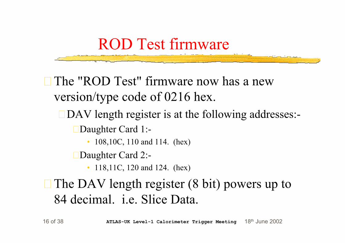
ROD Test firmware
z The "ROD Test" firmware now has a newversion/type code of 0216 hex.y DAV length register is at the following addresses:-
x Daughter Card 1:-• 108,10C, 110 and 114. (hex)
x Daughter Card 2:-• 118,11C, 120 and 124. (hex)
z The DAV length register (8 bit) powers up to84 decimal. i.e. Slice Data.
18th June 2002ATLAS-UK Level-1 Calorimeter Trigger Meeting17 of 38
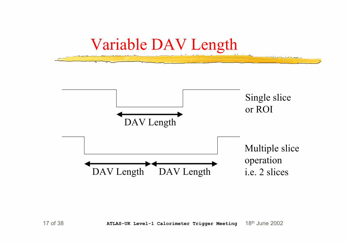
Variable DAV Length
DAV Length
Single sliceor ROI
DAV Length DAV Length
Multiple sliceoperationi.e. 2 slices

18th June 2002ATLAS-UK Level-1 Calorimeter Trigger Meeting18 of 38
Design Verification
z Performed limited tests in R25 HDL usingDSS and ROD with the Glink Tx and Rxcards.y Results indicated that basic data transfer was still
working.
y Release firmware to Bruce on 28th May 2002 forextensive tests.
x At time of writing have not received any complaints.

18th June 2002ATLAS-UK Level-1 Calorimeter Trigger Meeting19 of 38
ROD Test Setup
18th June 2002ATLAS-UK Level-1 Calorimeter Trigger Meeting20 of 38
GIO daughter card - New versions
z The new LVDS Source for GIO hasversion/type code of “0612” hex.
z The new LVDS Sink for GIO has version/typecode of “0A13” hex.

18th June 2002ATLAS-UK Level-1 Calorimeter Trigger Meeting21 of 38
GIO daughter card - Source 1
z Orbit register (32 bits) is at:-y Daughter Card 1:-
x 108,10C, 110 and 114. (hex)
y Daughter Card 2:-x 118,11C, 120 and 124. (hex)
z Notey This occupies the same address space as DAV
register in "ROD test" design.
18th June 2002ATLAS-UK Level-1 Calorimeter Trigger Meeting22 of 38
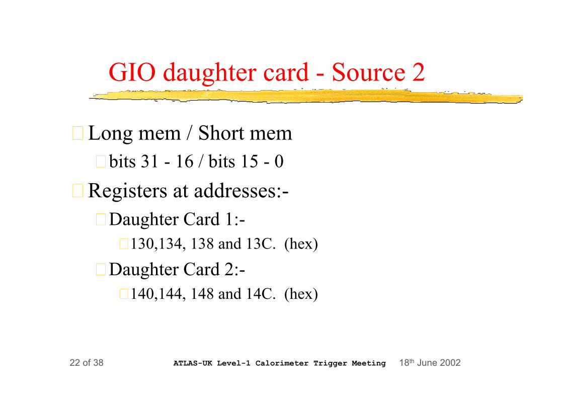
GIO daughter card - Source 2
z Long mem / Short memy bits 31 - 16 / bits 15 - 0
z Registers at addresses:-y Daughter Card 1:-
x 130,134, 138 and 13C. (hex)
y Daughter Card 2:-x 140,144, 148 and 14C. (hex)
18th June 2002ATLAS-UK Level-1 Calorimeter Trigger Meeting23 of 38
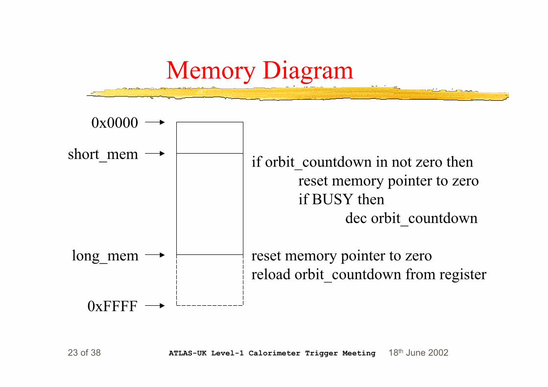
Memory Diagram
0x0000
short_mem
long_mem
0xFFFF
if orbit_countdown in not zero thenreset memory pointer to zeroif BUSY then
dec orbit_countdown
reset memory pointer to zeroreload orbit_countdown from register

18th June 2002ATLAS-UK Level-1 Calorimeter Trigger Meeting24 of 38
18th June 2002ATLAS-UK Level-1 Calorimeter Trigger Meeting25 of 38
Possible Problems / Design Features
y The design relies upon the counter in the FPGAkeeping track with the address counter in thememory chips.
y Due to latency in the design short_mem andlong_mem should be set to a value of 2 less thanthe last data memory location required.
18th June 2002ATLAS-UK Level-1 Calorimeter Trigger Meeting26 of 38
Design Features Continued...
z Setting both long_mem and short_mem to0x0000 will disable the RESET mechanismand allow rollover at 32k as normal.
z After loading the orbit_countdown registeryou should apply an “Address Counter Reset”to ensure that the value is transferred to theorbit_countdown counter.

18th June 2002ATLAS-UK Level-1 Calorimeter Trigger Meeting27 of 38
GIO daughter card - Sink 1
z Compare Mask (20 bits)y Daughter Card 1:-
x 108,10C, 110 and 114. (hex)
y Daughter Card 2:-x 118,11C, 120 and 124. (hex)

18th June 2002ATLAS-UK Level-1 Calorimeter Trigger Meeting28 of 38
GIO Daughter Card - Sink 2
z Set bit high to disable the comparison of thatdata bit.y This allows the GIO data width of 32 bits to run
within a design that originally allowed a data withof 80 bits (Previous daughter cards such as Glinkor LVDS has data widths of 4x20).
x FPGA 1 (5) - 20 bits
x FPGA 2 (6) - 12 bits• () indicate Daughter card in slot 2.

18th June 2002ATLAS-UK Level-1 Calorimeter Trigger Meeting29 of 38
Automatic Comparison
FPGA 1(5)
FPGA 2(6)
FPGA 3(7)
FPGA 4(8)
Ch A
Ch B
Ch C
Ch D
Glink CardsA, B, C and Dare 20 bits.
GIO CardA - 20 bitsB - 12 bits

18th June 2002ATLAS-UK Level-1 Calorimeter Trigger Meeting30 of 38

18th June 2002ATLAS-UK Level-1 Calorimeter Trigger Meeting31 of 38
Design Verification
z Performed limited tests in R25 HDL usingRAMP data and LOOPBACK card.y Results seemed to indicate that the RESET
mechanism was working as expected.
y Firmware ready for release for extensive tests inR1 on 27th May 2002.

18th June 2002ATLAS-UK Level-1 Calorimeter Trigger Meeting32 of 38
GIO Test Setup
18th June 2002ATLAS-UK Level-1 Calorimeter Trigger Meeting33 of 38
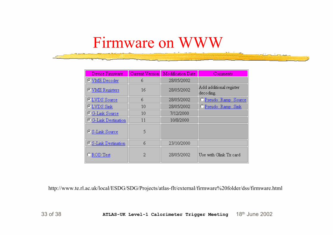
Firmware on WWW
http://www.te.rl.ac.uk/local/ESDG/SDG/Projects/atlas-flt/external/firmware%20folder/dss/firmware.html
18th June 2002ATLAS-UK Level-1 Calorimeter Trigger Meeting34 of 38
Additional Requests 1
z It has been suggested that these additionalregisters cause problems with the diagnosticsoftware as different cards have differentregister space, requiring a different moduledefinition file for each combination ofdaughter cards.
z “Solution” is to add extra un-used registers.

18th June 2002ATLAS-UK Level-1 Calorimeter Trigger Meeting35 of 38
Additional Requests 2
z If required, additional r/w registers can beadded.y This could affect up to 6 designs so is not a trivial
task.
z Don’t mention the 6 1/2 hours required to adda divide by 2 circuit to the 40 MHz clock tothe CP chip for Richard.
18th June 2002ATLAS-UK Level-1 Calorimeter Trigger Meeting36 of 38
Compromise
z Have agreed to add “dummy” registers to allfuture DSS Data FPGA designs.
z This modification will not be released until Iam required to change a design for “technical”reasons.

18th June 2002ATLAS-UK Level-1 Calorimeter Trigger Meeting37 of 38
Acknowlegements

18th June 2002ATLAS-UK Level-1 Calorimeter Trigger Meeting38 of 38
Summary
z 5 designs modified intotal.
z Basic tests in R25 HDLindicate that PCO 001has been completed.
z Require furtherextensive testing in R1.