DS(P)E*KD2 - grieger-automation.com eng... · DS(P)E*KD2 EXPLOSION-PROOF VERSION ... Fluid...
24
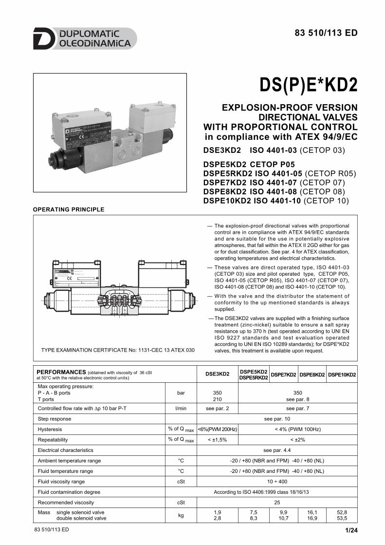
83 510/113 ED 1/24 83 510/113 ED OPERATING PRINCIPLE — The explosion-proof directional valves with proportional control are in compliance with ATEX 94/9/EC standards and are suitable for the use in potentially explosive atmospheres, that fall within the ATEX II 2GD either for gas or for dust classification. See par. 4 for ATEX classification, operating temperatures and electrical characteristics. — These valves are direct operated type, ISO 4401-03 (CETOP 03) size and pilot operated type, CETOP P05, ISO 4401-05 (CETOP R05), ISO 4401-07 (CETOP 07), ISO 4401-08 (CETOP 08) and ISO 4401-10 (CETOP 10). — With the valve and the distributor the statement of conformity to the up mentioned standards is always supplied. — The DSE3KD2 valves are supplied with a finishing surface treatment (zinc-nickel) suitable to ensure a salt spray resistance up to 370 h (test operated according to UNI EN ISO 9227 standards and test evaluation operated according to UNI EN ISO 10289 standards); for DSPE*KD2 valves, this treatment is available upon request. DSE3KD2 ISO 4401-03 (CETOP 03) DSPE5KD2 CETOP P05 DSPE5RKD2 ISO 4401-05 (CETOP R05) DSPE7KD2 ISO 4401-07 (CETOP 07) DSPE8KD2 ISO 4401-08 (CETOP 08) DSPE10KD2 ISO 4401-10 (CETOP 10) DS(P)E*KD2 EXPLOSION-PROOF VERSION DIRECTIONAL VALVES WITH PROPORTIONAL CONTROL in compliance with ATEX 94/9/EC TYPE EXAMINATION CERTIFICATE No: 1131-CEC 13 ATEX 030 DSE3KD2 DSPE5KD2 DSPE5RKD2 DSPE7KD2 DSPE8KD2 DSPE10KD2 Max operating pressure: P - A - B ports T ports bar 350 210 350 see par. 8 Controlled flow rate with ∆p 10 bar P-T l/min see par. 2 see par. 7 Step response see par. 10 Hysteresis % of Q max <6%(PWM 200Hz) < 4% (PWM 100Hz) Repeatability % of Q max < ±1,5% < ±2% Electrical characteristics see par. 4.4 Ambient temperature range °C -20 / +80 (NBR and FPM) -40 / +80 (NL) Fluid temperature range °C -20 / +80 (NBR and FPM) -40 / +80 (NL) Fluid viscosity range cSt 10 ÷ 400 Fluid contamination degree According to ISO 4406:1999 class 18/16/13 Recommended viscosity cSt 25 Mass single solenoid valve double solenoid valve kg 1,9 2,8 7,5 8,3 9,9 10,7 16,1 16,9 52,8 53,5 PERFORMANCES (obtained with viscosity of 36 cSt at 50°C with the relative electronic control units)
Transcript of DS(P)E*KD2 - grieger-automation.com eng... · DS(P)E*KD2 EXPLOSION-PROOF VERSION ... Fluid...
83 510/113 ED 1/24
83 510/113 ED
OPERATING PRINCIPLE
— The explosion-proof directional valves with proportional
control are in compliance with ATEX 94/9/EC standards
and are suitable for the use in potentially explosive
atmospheres, that fall within the ATEX II 2GD either for gas
or for dust classification. See par. 4 for ATEX classification,
operating temperatures and electrical characteristics.
— These valves are direct operated type, ISO 4401-03
(CETOP 03) size and pilot operated type, CETOP P05,
ISO 4401-05 (CETOP R05), ISO 4401-07 (CETOP 07),
ISO 4401-08 (CETOP 08) and ISO 4401-10 (CETOP 10).
— With the valve and the distributor the statement of
conformity to the up mentioned standards is always
supplied.
— The DSE3KD2 valves are supplied with a finishing surface
treatment (zinc-nickel) suitable to ensure a salt spray
resistance up to 370 h (test operated according to UNI EN
ISO 9227 standards and test evaluation operated
according to UNI EN ISO 10289 standards); for DSPE*KD2
valves, this treatment is available upon request.
DSE3KD2 ISO 4401-03 (CETOP 03)
DSPE5KD2 CETOP P05DSPE5RKD2 ISO 4401-05 (CETOP R05)DSPE7KD2 ISO 4401-07 (CETOP 07)DSPE8KD2 ISO 4401-08 (CETOP 08)DSPE10KD2 ISO 4401-10 (CETOP 10)
DS(P)E*KD2 EXPLOSION-PROOF VERSION
DIRECTIONAL VALVESWITH PROPORTIONAL CONTROLin compliance with ATEX 94/9/EC
TYPE EXAMINATION CERTIFICATE No: 1131-CEC 13 ATEX 030
DSE3KD2 DSPE5KD2DSPE5RKD2
DSPE7KD2 DSPE8KD2 DSPE10KD2
Max operating pressure:
P - A - B ports
T ports
bar 350
210
350
see par. 8
Controlled flow rate with ∆p 10 bar P-T l/min see par. 2 see par. 7
Step response see par. 10
Hysteresis % of Q max <6%(PWM 200Hz) < 4% (PWM 100Hz)
Repeatability % of Q max < ±1,5% < ±2%
Electrical characteristics see par. 4.4
Ambient temperature range °C -20 / +80 (NBR and FPM) -40 / +80 (NL)
Fluid temperature range °C -20 / +80 (NBR and FPM) -40 / +80 (NL)
Fluid viscosity range cSt 10 ÷ 400
Fluid contamination degree According to ISO 4406:1999 class 18/16/13
Recommended viscosity cSt 25
Mass single solenoid valvedouble solenoid valve
kg1,92,8
7,58,3
9,910,7
16,116,9
52,853,5
PERFORMANCES (obtained with viscosity of 36 cSt
at 50°C with the relative electronic control units)
83 510/113 ED 2/24
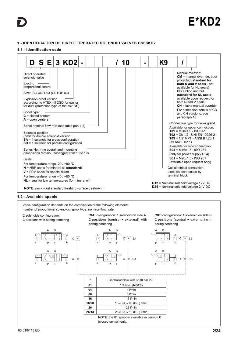
E*KD21 - IDENTIFICATION OF DIRECT OPERATED SOLENOID VALVES DSE3KD2
1.1 - Identification code
1.2 - Available spools
Seals:
For temperature range -20 / +80 °C
N = NBR seals for mineral oil (standard)
V = FPM seals for special fluids
For temperature range -40 / +80 °C
NL = seal for low temperatures (for mineral oil)
Connection type for cable gland
Available for upper connection:T01 = M20x1.5 - ISO 261T02 = Gk 1/2 - UNI EN 10226-2T03 = 1/2” NPT - ANSI B1.20.1(ex ANSI B2.1)
Available for side connection:S04 = M16x1.5 - ISO 261
(only for power supply D24)
S01 = M20x1.5 - ISO 261(available upon request only)
Manual override:CM = manual override, bootprotected (standard forboth N and V seals - notavailable for NL seals)CB = blind ring nut(standard for NL seals -available upon request forboth N and V seals)CH = lever manual override
For dimension details of CBand CH versions, seeparagraph 18
Spool type:C = closed centersA = open centers
Series No.: (the overall and mountingdimensions remain unchanged from 10 to 19)
D S 3E KD2 - / 10 - K9 /
Direct operatedsolenoid valve
Electricproportional control
Size: ISO 4401-03 (CETOP 03)
Coil electrical connection:
electrical connection byterminal block
Explosion-proof version, according to ATEX - II 2GD for gas orfor dust (protection type of the coil: “d”)
Spool nominal flow rate (see table par. 1.2)
Solenoid position (omit for double solenoid version):SA = 1 solenoid for cross configurationSB = 1 solenoid for parallel configuration
SB*A
C
A *
*
8
4
l/min
l/min
16 l/min
l/min
p 10 bar P-T
08
04
*
16
26 26
Portata nominale con
* SAA
* SAC * SBC
P T
A B
aP T
A B
a b
P T
A B
b
P T
A B
b
P T
A B
aP T
A B
a b
Valve configuration depends on the combination of the following elements:
number of proportional solenoids, spool type, nominal flow rate.
2 solenoids configuration:
3 positions with spring centering
“SA” configuration: 1 solenoid on side A.
2 positions (central + external) with
spring centering
“SB” configuration: 1 solenoid on side B.
2 positions (central + external) with
spring centering
Controlled flow with
* Controlled flow with ∆p10 bar P-T
01 1,3 l/min (NOTE)
04 4 l/min
08 8 l/min
16 16 l/min
16/08 16 (P-A) / 08 (B-T) l/min
26 26 l/min
26/13 26 (P-A) / 13 (B-T) l/min
NOTE: the 01 spool is available in version C
(closed center) only.
D12 = Nominal solenoid voltage 12V DCD24 = Nominal solenoid voltage 24V DC
NOTE: zinc-nickel standard finishing surface treatment.
83 510/113 ED 3/24
E*KD2
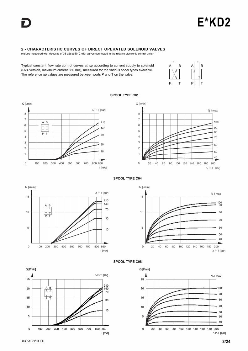
2 - CHARACTERISTIC CURVES OF DIRECT OPERATED SOLENOID VALVES (values measured with viscosity of 36 cSt at 50°C with valves connected to the relative electronic control units)
Typical constant flow rate control curves at ∆p according to current supply to solenoid
(D24 version, maximum current 860 mA), measured for the various spool types available.
The reference ∆p values are measured between ports P and T on the valve.
SPOOL TYPE C04
SPOOL TYPE C08
10
30
70140140210210
P-T [bar]P-T [bar]
0
5
10
15
20
25
Q [l/min]Q [l/min]
I [mA]I [mA]
200 400 600 800 860100100 300300 500500 700700
P T
A B
4040
% I max% I max
5050
6060
7070
8080
9090
100100
00
55
1010
1515
2020
2525
Q [l/min]Q [l/min]
P-T [bar]P-T [bar]
2002004040 8080 120120 160160 1801802020 6060 100100 140140
10
30
70
140
210
0
I [mA]
200 400 600 800 860100 300 500 700
P-T [bar]
5
10
15
Q [l/min]
P T
A B
40
% I max
50
60
70
80
90100
0
5
10
15
Q [l/min]
P-T [bar]
20040 80 120 160 18020 60 100 140
SPOOL TYPE C01

83 510/113 ED 4/24
E*KD2
SPOOL TYPE C26
SPOOL TYPE A04
P T
A B
10
30
70
140210
0
5
1010
1515
2020
2525
3535
3030
P-T [bar]P-T [bar]
I [mA]I [mA]
200 400 600 800 860100100 300300 500500 700700
Q [l/min]Q [l/min]
4040
% I max% I max
50506060
7070
8080
9090
100100
00
55
1010
1515
2020
2525
3535
3030
Q [l/min]Q [l/min]
P-T [bar]P-T [bar]
2002004040 8080 120120 160160 1801802020 6060 100100 140140
4545
4040
10
30
70
140
210
0
I [mA]
200 400 600 800 860100 300 500 700
P-T [bar]
5
10
15
Q [l/min]
P T
A B
40
% I max
50
60
70
80
90100
0
5
10
15
Q [l/min]
P-T [bar]
20040 80 120 160 18020 60 100 140
SPOOL TYPE C16
10
210
30
70 - 14070 - 140
0
5
1010
1515
2020
2525
3030
Q [l/min]Q [l/min]
I [mA]I [mA]
200200 400400 600 800800 860860100100 300300 500500 700700
P-T [bar]
P T
A B
4040
% I max% I max
5050
6060
7070
8080
9090
100100
00
P-T [bar]P-T [bar]
2002004040 8080 120120 160160
55
1010
1515
2020
2525
Q [l/min]Q [l/min]
1801802020 6060 100100 140140
3535
3030
83 510/113 ED 5/24
E*KD2
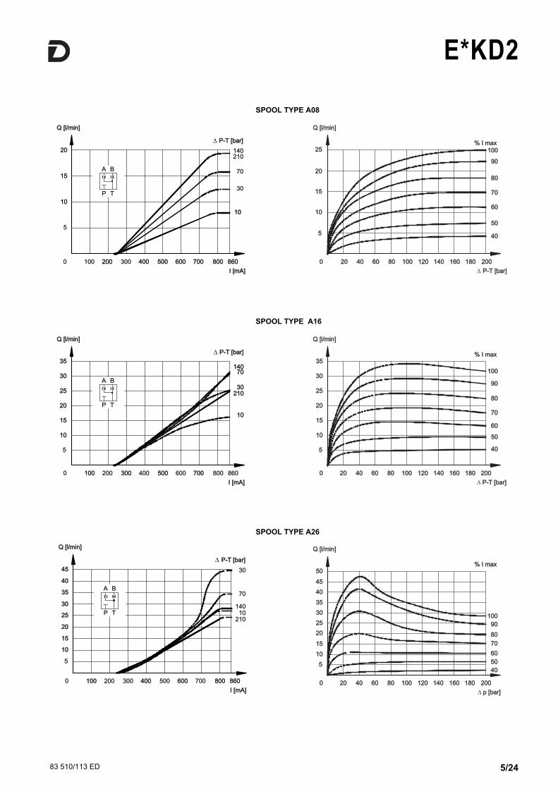
SPOOL TYPE A08
1010
30
70
140210
0
5
1010
1515
I [mA]I [mA]
200200 400400 600600 800800 860860100 300 500500 700700
Q [l/min]Q [l/min]
P-T [bar]P-T [bar]
2020
P T
A B
4040
% I max% I max
5050
6060
7070
8080
9090
100100
00
P-T [bar]P-T [bar]
2002004040 8080 120120 160160
55
1010
1515
2020
2525
Q [l/min]Q [l/min]
1801802020 6060 100100 140140
SPOOL TYPE A16
SPOOL TYPE A26
210210
1010
3030
7070140140
0
I [mA]I [mA]
200 400 600 800 860100100 300300 500500 700700
Q [l/min]Q [l/min]
5
1010
1515
2020
2525
3535
3030
P-T [bar]P-T [bar]
P T
A B
4040
% I max% I max
5050
6060
7070
8080
9090
100100
00
55
1010
1515
2020
2525
3535
3030
Q [l/min]Q [l/min]
P-T [bar]P-T [bar]
2002004040 8080 120120 160160 1801802020 6060 100100 140140
4040
% I max% I max
5050
6060
7070
8080
9090
100100
00
55
1010
1515
2020
2525
3535
3030
Q [l/min]Q [l/min]
p [bar]p [bar]
2002004040 8080 120120 160160 1801802020 6060 100100 140140
4545
4040
5050
10
30
70
140
210
5
1010
1515
2020
2525
3535
3030
Q [l/min]Q [l/min]
4545
4040
P-T [bar]P-T [bar]
0
I [mA]I [mA]
200 400400 600600 800800 860860100100 300 500 700
P T
A B
83 510/113 ED 6/24
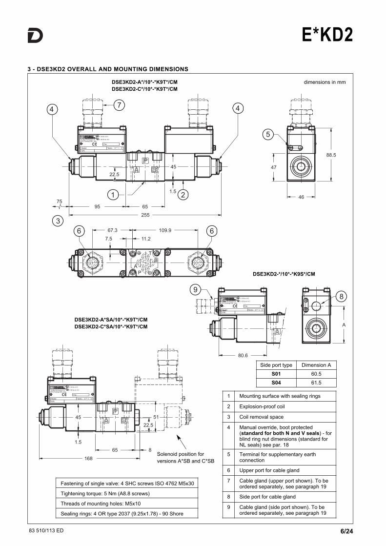
E*KD23 - DSE3KD2 OVERALL AND MOUNTING DIMENSIONS
dimensions in mmDSE3KD2-A*/10*-*K9T*/CM
DSE3KD2-C*/10*-*K9T*/CM
DSE3KD2-A*SA/10*-*K9T*/CM
DSE3KD2-C*SA/10*-*K9T*/CM
Fastening of single valve: 4 SHC screws ISO 4762 M5x30
Tightening torque: 5 Nm (A8.8 screws)
Threads of mounting holes: M5x10
Sealing rings: 4 OR type 2037 (9.25x1.78) - 90 Shore
1 Mounting surface with sealing rings
2 Explosion-proof coil
3 Coil removal space
4 Manual override, boot protected(standard for both N and V seals) - forblind ring nut dimensions (standard forNL seals) see par. 18
5 Terminal for supplementary earthconnection
6 Upper port for cable gland
7 Cable gland (upper port shown). To beordered separately, see paragraph 19
8 Side port for cable gland
9 Cable gland (side port shown). To beordered separately, see paragraph 19
Side port type Dimension A
S01 60.5
S04 61.5
Solenoid position for
versions A*SB and C*SB
DSE3KD2-*/10*-*K9S*/CM
83 510/113 ED 7/24
E*KD2
MARKING FOR GASES, VAPOURS, MISTS
II 2G Ex d IIC T4 Gb (-40°C Ta +80°C)
EX: Specific marking of explosion protection as ATEX 94/9/EC
directive and related technical specification requests.
II: Group II for surface plants
2: Category 2 high protection, eligible for zone 1
(therefore also eligible for category 3 zone 2)
G: Type of atmosphere with gases, vapours, mists
Ex d: “d” protection type, explosion-proof case
IIC: Gas group
(therefore also eligible for group IIA and IIB)
T4: Temperature class (max surface temperature)
Gb: EPL protection level for electrical devices
-40°C Ta +80°C: Ambient temperature range
MARKING FOR DUSTS
II 2D Ex tb IIIC T154°C Db IP66/IP68 (-40°C Ta +80°C)
EX: Specific marking of explosion protection as ATEX 94/9/EC
directive and related technical specification requests.
II: Group II for surface plants
2: Category 2 high protection, eligible for zone 21
(therefore also eligible for category 3 zone 22)
D: Type of atmosphere with dusts
Ex tb : ‘tb’ protection type
IIIC:Dusts group
(therefore also eligible for group IIIA and IIIB)
T154°C: Temperature class (max surface temperature)
Db: EPL protection level for electrical devices
IP66/IP68: Valve IP degree
-40°C Ta +80°C: Ambient temperature range
4 - ATEX CLASSIFICATION, OPERATING TEMPERATURES AND ELECTRICAL CHARACTERISTICS
For valves suitable for application and installation in potentially explosive atmospheres, according to ATEX directive prescriptions,
Duplomatic certificated the combination valve-coil; the supply always includes the declaration of conformity to the directive and the
operating and maintenance manual, that contains all the informations needed for a correct use of the valve in potentially explosive
environments.
Coils assembled on these valves have been separately certified according to ATEX directive and so they are suitable for use in potentially
explosive atmospheres.
4.1 - Valve ATEX classification
The valves can be used for applications and installations in potentially explosive atmospheres that fall within either the ATEX II 2G or the ATEX
II 2D classification, with the follow marking:
4.2 - Coils ATEX classification
The coil of the explosion-proof valves is identified with its own tag, which carries the relative ATEX marking. The mechanical construction of
the coil housing is made in order to ensure its resistance to possible internal explosion and to avoid any explosion propagation to
the outside environment, matching an “Ex d” type protection (explosion-proof coil).
Moreover, the solenoid is designed to maintain its surface temperature below the limits specified to the relevant class.
The R* coils (for alternating current supply) contain a built-in rectifier bridge.
Here below you find the coils marking:
MARKING FOR GASES, VAPOURS, MISTS
II 2G IIC T4 Gb (-20°C Ta +80°C) for both N and V seals
II 2G IIC T4 Gb (-40°C Ta +80°C) for NL seals
EX: Specific marking of explosion protection as ATEX 94/9/EC
directive and related technical specification requests.
II: Group II for surface plants
2: Category 2 high protection, eligible for zone 1
(therefore also eligible for category 3 zone 2)
G: Type of atmosphere with gases, vapours, mists
IIC: Gas group
(therefore also eligible for group IIA and IIB)
T4: Temperature class (max surface temperature)
Gb: EPL protection level for electrical devices
-20°C Ta +80°C: Ambient temperature range for valves with both N
and V seals
-40°C Ta +80°C: Ambient temperature range for valves with NL
seals
MARKING FOR DUSTS
II 2D IIIC T154°C Db (-20°C Ta +80°C) for both N and V seals
II 2D IIIC T154°C Db (-40°C Ta +80°C) for NL seals
EX: Specific marking of explosion protection as ATEX 94/9/EC
directive and related technical specification requests.
II: Group II for surface plants
2: Category 2 high protection, eligible for zone 21
(therefore also eligible for category 3 zone 22)
D: Type of atmosphere with dusts
IIIC:Dusts group
(therefore also eligible for group IIIA and IIIB)
T154°C: Temperature class (max surface temperature)
Db: EPL protection level for electrical devices
-20°C Ta +80°C: Ambient temperature range for valves with both N
and V seals
-40°C Ta +80°C: Ambient temperature range for valves with NL seals
83 510/113 ED 8/24
E*KD2
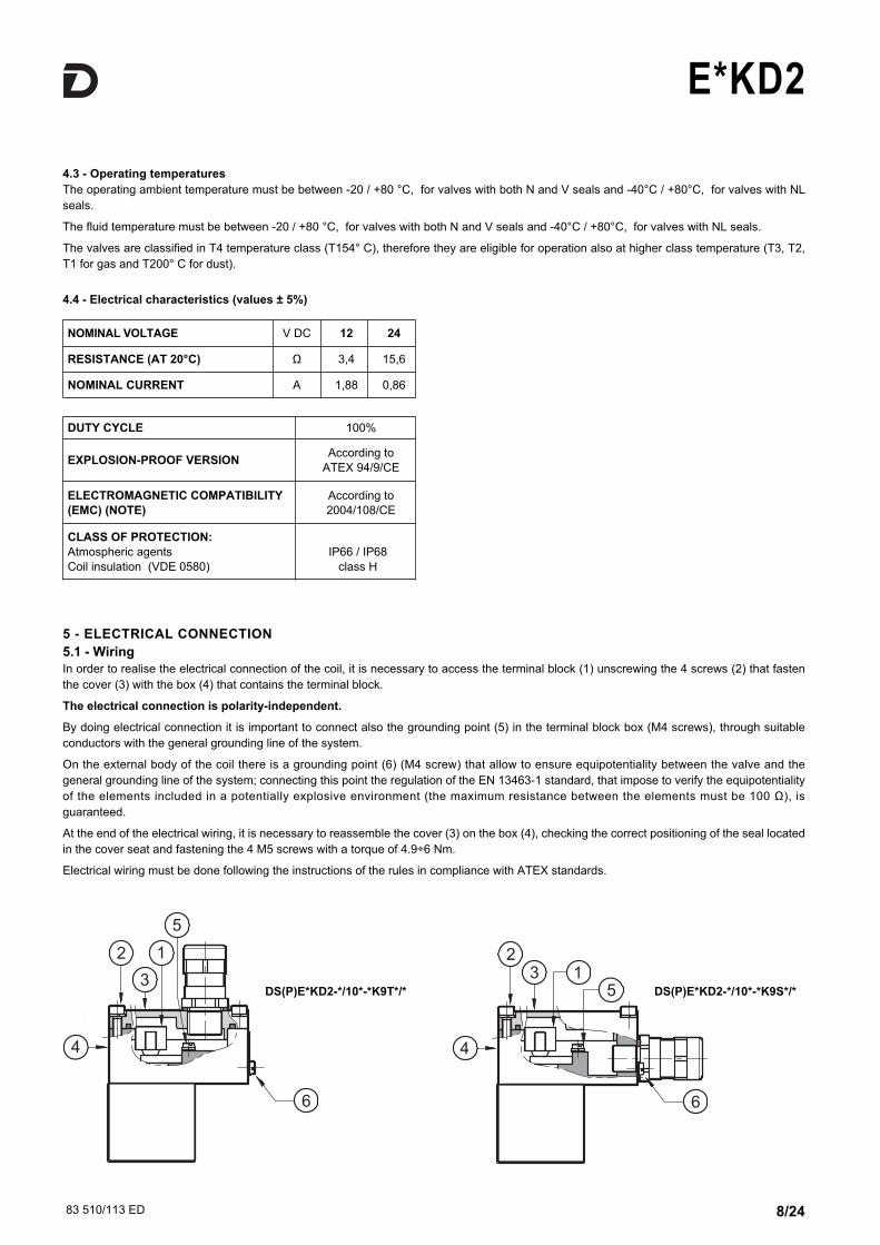
5 - ELECTRICAL CONNECTION
5.1 - Wiring
In order to realise the electrical connection of the coil, it is necessary to access the terminal block (1) unscrewing the 4 screws (2) that fasten
the cover (3) with the box (4) that contains the terminal block.
The electrical connection is polarity-independent.
By doing electrical connection it is important to connect also the grounding point (5) in the terminal block box (M4 screws), through suitable
conductors with the general grounding line of the system.
On the external body of the coil there is a grounding point (6) (M4 screw) that allow to ensure equipotentiality between the valve and the
general grounding line of the system; connecting this point the regulation of the EN 13463-1 standard, that impose to verify the equipotentiality
of the elements included in a potentially explosive environment (the maximum resistance between the elements must be 100 Ω), is
guaranteed.
At the end of the electrical wiring, it is necessary to reassemble the cover (3) on the box (4), checking the correct positioning of the seal located
in the cover seat and fastening the 4 M5 screws with a torque of 4.9÷6 Nm.
Electrical wiring must be done following the instructions of the rules in compliance with ATEX standards.
4.3 - Operating temperatures
The operating ambient temperature must be between -20 / +80 °C, for valves with both N and V seals and -40°C / +80°C, for valves with NL
seals.
The fluid temperature must be between -20 / +80 °C, for valves with both N and V seals and -40°C / +80°C, for valves with NL seals.
The valves are classified in T4 temperature class (T154° C), therefore they are eligible for operation also at higher class temperature (T3, T2,
T1 for gas and T200° C for dust).
4.4 - Electrical characteristics (values ± 5%)
DS(P)E*KD2-*/10*-*K9T*/* DS(P)E*KD2-*/10*-*K9S*/*
NOMINAL VOLTAGE V DC 12 24
RESISTANCE (AT 20°C) Ω 3,4 15,6
NOMINAL CURRENT A 1,88 0,86
DUTY CYCLE 100%
EXPLOSION-PROOF VERSIONAccording to
ATEX 94/9/CE
ELECTROMAGNETIC COMPATIBILITY
(EMC) (NOTE)
According to
2004/108/CE
CLASS OF PROTECTION:
Atmospheric agents
Coil insulation (VDE 0580)
IP66 / IP68
class H
83 510/113 ED 9/24
E*KD2
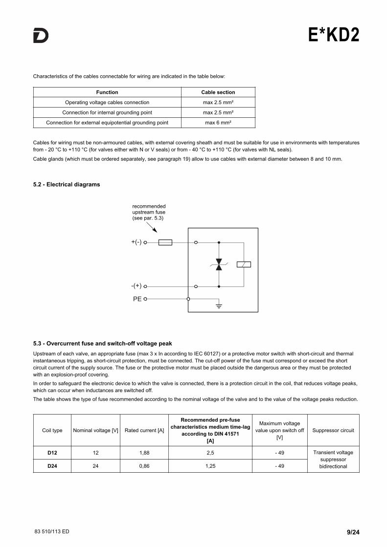
5.2 - Electrical diagrams
5.3 - Overcurrent fuse and switch-off voltage peak
Upstream of each valve, an appropriate fuse (max 3 x In according to IEC 60127) or a protective motor switch with short-circuit and thermal
instantaneous tripping, as short-circuit protection, must be connected. The cut-off power of the fuse must correspond or exceed the short
circuit current of the supply source. The fuse or the protective motor must be placed outside the dangerous area or they must be protected
with an explosion-proof covering.
In order to safeguard the electronic device to which the valve is connected, there is a protection circuit in the coil, that reduces voltage peaks,
which can occur when inductances are switched off.
The table shows the type of fuse recommended according to the nominal voltage of the valve and to the value of the voltage peaks reduction.
Characteristics of the cables connectable for wiring are indicated in the table below:
Cables for wiring must be non-armoured cables, with external covering sheath and must be suitable for use in environments with temperatures
from - 20 °C to +110 °C (for valves either with N or V seals) or from - 40 °C to +110 °C (for valves with NL seals).
Cable glands (which must be ordered separately, see paragraph 19) allow to use cables with external diameter between 8 and 10 mm.
Function Cable section
Operating voltage cables connection max 2.5 mm²
Connection for internal grounding point max 2.5 mm²
Connection for external equipotential grounding point max 6 mm²
Coil type Nominal voltage [V] Rated current [A]
Recommended pre-fuse
characteristics medium time-lag
according to DIN 41571
[A]
Maximum voltage
value upon switch off
[V]
Suppressor circuit
D12 12 1,88 2,5 - 49 Transient voltage
suppressor
bidirectionalD24 24 0,86 1,25 - 49
recommendedupstream fuse(see par. 5.3)
83 510/113 ED 10/24
E*KD2
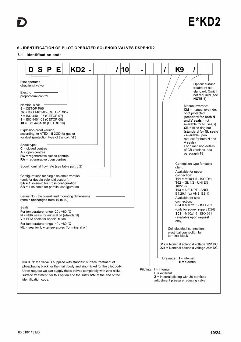
6.1 - Identification code
6 - IDENTIFICATION OF PILOT OPERATED SOLENOID VALVES DSPE*KD2
Connection type for cablegland
Available for upperconnection:T01 = M20x1.5 - ISO 261T02 = Gk 1/2 - UNI EN10226-2T03 = 1/2” NPT - ANSIB1.20.1 (ex ANSI B2.1)
Available for sideconnection:S04 = M16x1.5 - ISO 261
(only for power supply D24)
S01 = M20x1.5 - ISO 261(available upon requestonly)
Seals:
For temperature range -20 / +80 °CN = NBR seals for mineral oil (standard)V = FPM seals for special fluids
For temperature range -40 / +80 °CNL = seal for low temperatures (for mineral oil)
Manual override:CM = manual override,boot protected(standard for both Nand V seals - notavailable for NL seals)CB = blind ring nut(standard for NL seals- available uponrequest for both N andV seals)For dimension detailsof CB versions, seeparagraph 18
Coil electrical connection: electrical connection byterminal block
Drainage: I = internalE = external
Nominal size: 5 = CETOP P05 5R = ISO 4401-05 (CETOP R05)7 = ISO 4401-07 (CETOP 07)8 = ISO 4401-08 (CETOP 08)10 = ISO 4401-10 (CETOP 10)
Piloting: I = internalE = externalZ = internal piloting with 30 bar fixed adjustment pressure reducing valve
D12 = Nominal solenoid voltage 12V DCD24 = Nominal solenoid voltage 24V DC
Spool type:C = closed centresA = open centresRC = regenerative closed centresRA = regenerative open centres
Pilot operateddirectional valve
Electricproportional control
Spool nominal flow rate (see table par. 6.2)
Configurations for single solenoid version(omit for double solenoid version):SA = 1 solenoid for cross configurationSB = 1 solenoid for parallel configuration
D S P E - / 10 - K9 //KD2
Explosion-proof version, according to ATEX - II 2GD for gas orfor dust (protection type of the coil: “d”)
Series No. (the overall and mounting dimensionsremain unchanged from 10 to 19)
Option: surfacetreatment notstandard. Omit ifnot required (seeNOTE 1)
NOTE 1: the valve is supplied with standard surface treatment of
phosphating black for the main body and zinc-nickel for the pilot body.
Upon request we can supply these valves completely with zinc-nickel
surface treatment; for this option add the suffix /W7 at the end of the
identification code.
83 510/113 ED 11/24
E*KD2
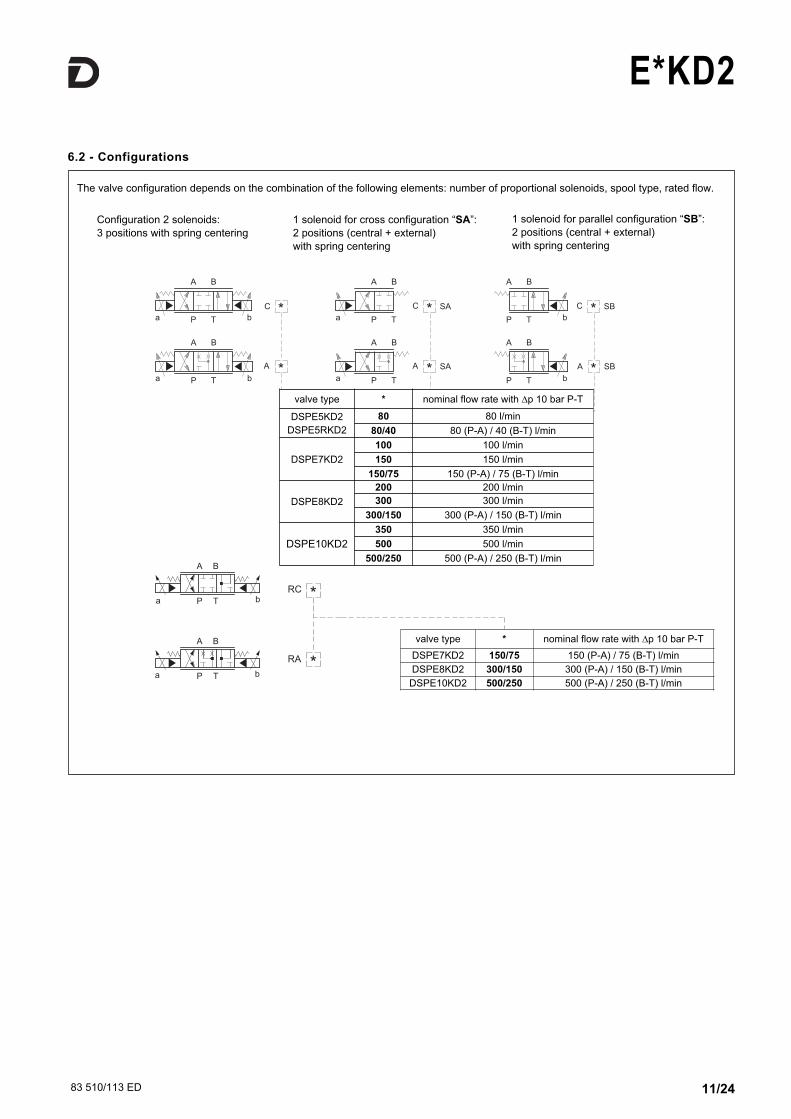
6.2 - Configurations
SB*A
C
A *
*
* SAA
* SAC * SBC
P T
A B
aP T
A B
a b
P T
A B
b
P T
A B
b
P T
A B
aP T
A B
a b
P
A
T
B
ba
P
A
T
B
ba*
*RC
RA
The valve configuration depends on the combination of the following elements: number of proportional solenoids, spool type, rated flow.
Configuration 2 solenoids:
3 positions with spring centering
1 solenoid for cross configuration “SA”:
2 positions (central + external)
with spring centering
1 solenoid for parallel configuration “SB”:
2 positions (central + external)
with spring centering
valve type * nominal flow rate with ∆p 10 bar P-T
DSPE5KD2
DSPE5RKD2
80 80 l/min
80/40 80 (P-A) / 40 (B-T) l/min
DSPE7KD2
100 100 l/min
150 150 l/min
150/75 150 (P-A) / 75 (B-T) l/min
DSPE8KD2
200 200 l/min
300 300 l/min
300/150 300 (P-A) / 150 (B-T) l/min
DSPE10KD2
350 350 l/min
500 500 l/min
500/250 500 (P-A) / 250 (B-T) l/min
valve type * nominal flow rate with ∆p 10 bar P-T
DSPE7KD2 150/75 150 (P-A) / 75 (B-T) l/min
DSPE8KD2 300/150 300 (P-A) / 150 (B-T) l/min
DSPE10KD2 500/250 500 (P-A) / 250 (B-T) l/min
83 510/113 ED 12/24
E*KD2
0
50
100
150
100 200
180
Q [l/min]
300 400 500
10
[Bar]P-T
100
20
30
50
I [mA]
600 700 800 860
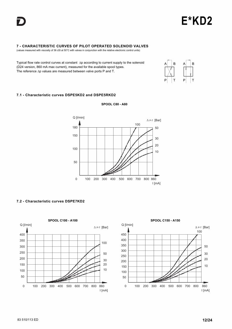
Typical flow rate control curves at constant ∆p according to current supply to the solenoid
(D24 version, 860 mA max current), measured for the available spool types.
The reference ∆p values are measured between valve ports P and T.
7 - CHARACTERISTIC CURVES OF PILOT OPERATED SOLENOID VALVES (values measured with viscosity of 36 cSt at 50°C with valves in conjunction with the relative electronic control units)
7.1 - Characteristic curves DSPE5KD2 and DSPE5RKD2
SPOOL C80 - A80
7.2 - Characteristic curves DSPE7KD2
[Bar]P-T
0
100
200
300
100 200
400
Q [l/min]
300 400 500
I [mA]
600 700 800 860
50
150
250
350
10
20
30
50
100
SPOOL C100 - A100 SPOOL C150 - A150
[Bar]P-T
100
10
20
30
50
0 100 200 300 400 500
I [mA]
600 700 800 860
100
200
300
450
Q [l/min]
50
150
250
350
400
83 510/113 ED 13/24
E*KD2
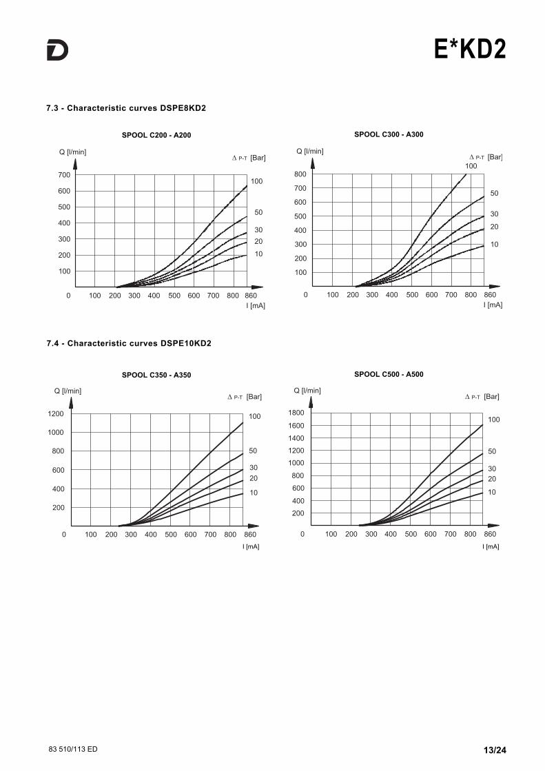
7.3 - Characteristic curves DSPE8KD2
SPOOL C300 - A300
[Bar]P-TQ [l/min]
10
20
30
50
100
0
200
400
600
100 200
800
300 400 500
I [mA]
600 700 800 860
100
300
500
700
[Bar]P-TQ [l/min]
10
20
30
50
100
0 100 200 300 400 500
I [mA]
600 700 800 860
200
400
600
100
300
500
700
SPOOL C200 - A200
SPOOL C500 - A500SPOOL C350 - A350
I [mA] I [mA]
7.4 - Characteristic curves DSPE10KD2
83 510/113 ED 14/24
E*KD2
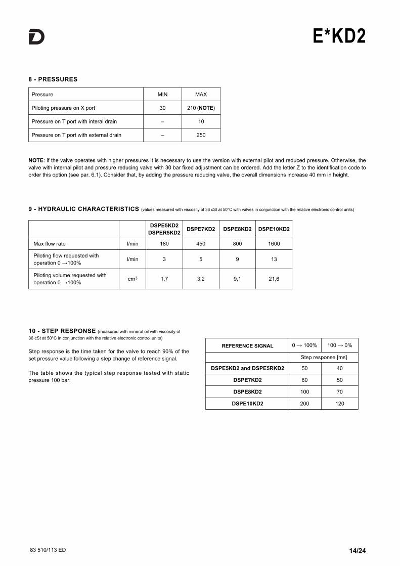
8 - PRESSURES
NOTE: if the valve operates with higher pressures it is necessary to use the version with external pilot and reduced pressure. Otherwise, the
valve with internal pilot and pressure reducing valve with 30 bar fixed adjustment can be ordered. Add the letter Z to the identification code to
order this option (see par. 6.1). Consider that, by adding the pressure reducing valve, the overall dimensions increase 40 mm in height.
Pressure MIN MAX
Piloting pressure on X port 30 210 (NOTE)
Pressure on T port with interal drain – 10
Pressure on T port with external drain – 250
9 - HYDRAULIC CHARACTERISTICS (values measured with viscosity of 36 cSt at 50°C with valves in conjunction with the relative electronic control units)
DSPE5KD2
DSPER5KD2DSPE7KD2 DSPE8KD2 DSPE10KD2
Max flow rate l/min 180 450 800 1600
Piloting flow requested with
operation 0 →100%l/min 3 5 9 13
Piloting volume requested with
operation 0 →100%cm3 1,7 3,2 9,1 21,6
10 - STEP RESPONSE (measured with mineral oil with viscosity of
36 cSt at 50°C in conjunction with the relative electronic control units)
Step response is the time taken for the valve to reach 90% of the
set pressure value following a step change of reference signal.
The table shows the typical step response tested with static
pressure 100 bar.
REFERENCE SIGNAL 0 → 100% 100 → 0%
Step response [ms]
DSPE5KD2 and DSPE5RKD2 50 40
DSPE7KD2 80 50
DSPE8KD2 100 70
DSPE10KD2 200 120
83 510/113 ED 15/24
E*KD2
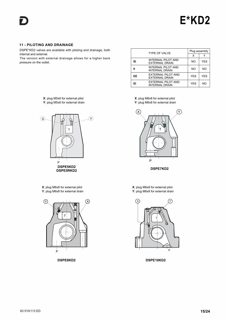
11 - PILOTING AND DRAINAGE
X: plug M5x6 for external pilot
Y: plug M5x6 for external drain
X: plug M6x8 for external pilot
Y: plug M6x8 for external drain
DSPE8KD2
DSPE7KD2
T
DSPE5KD2DSPE5RKD2
DSPE*KD2 valves are available with piloting and drainage, both
internal and external.
The version with external drainage allows for a higher back
pressure on the outlet.
P
X: plug M6x8 for external pilot
Y: plug M6x8 for external drain
X: plug M6x8 for external pilot
Y: plug M6x8 for external drain
DSPE10KD2
TYPE OF VALVEPlug assembly
X Y
IEINTERNAL PILOT ANDEXTERNAL DRAIN
NO YES
IIINTERNAL PILOT ANDINTERNAL DRAIN
NO NO
EEEXTERNAL PILOT ANDEXTERNAL DRAIN
YES YES
EIEXTERNAL PILOT ANDINTERNAL DRAIN
YES NO
83 510/113 ED 16/24
E*KD2
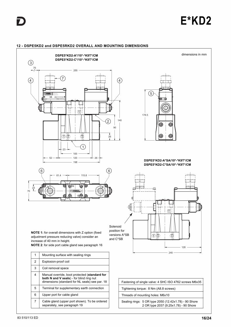
12 - DSPE5KD2 and DSPE5RKD2 OVERALL AND MOUNTING DIMENSIONS
dimensions in mm
Fastening of single valve: 4 SHC ISO 4762 screws M6x35
Tightening torque: 8 Nm (A8.8 screws)
Threads of mounting holes: M6x10
Sealing rings: 5 OR type 2050 (12.42x1.78) - 90 Shore
2 OR type 2037 (9.25x1.78) - 90 Shore
NOTE 1: for overall dimensions with Z option (fixed
adjustment pressure reducing valve) consider an
increase of 40 mm in height.
NOTE 2: for side port cable gland see paragraph 16
1 Mounting surface with sealing rings
2 Explosion-proof coil
3 Coil removal space
4 Manual override, boot protected (standard forboth N and V seals) - for blind ring nutdimensions (standard for NL seals) see par. 18
5 Terminal for supplementary earth connection
6 Upper port for cable gland
7 Cable gland (upper port shown). To be ordered
separately, see paragraph 19
DSPE5*KD2-A*/10*-*K9T*/CM
DSPE5*KD2-C*/10*-*K9T*/CM
DSPE5*KD2-A*SA/10*-*K9T*/CM
DSPE5*KD2-C*SA/10*-*K9T*/CM
Solenoid
position for
versions A*SB
and C*SB

83 510/113 ED 17/24
E*KD2
13 - DSPE7KD2 OVERALL AND MOUNTING DIMENSIONS
dimensions in mm
NOTE 1: for overall dimensions with Z option (fixed
adjustment pressure reducing valve) consider an
increase of 40 mm in height.
NOTE 2: for side port cable gland see paragraph 16
Fastening of single valve: 4 SHC screws ISO 4762 M10x60
2 SHC screws ISO 4762 M6x60
Tightening torque: M10x60: 40 Nm (A8.8 screws)
M6x60: 8 Nm (A8.8 screws)
Threads of mounting holes: M6x18; M10x18
Sealing rings: 4 OR type 130 (22.22X2.62) - 90 Shore
2 OR type 2043 (10.82x1.78) - 90 Shore
1 Mounting surface with sealing rings
2 Explosion-proof coil
3 Coil removal space
4 Manual override, boot protected (standard forboth N and V seals) - for blind ring nutdimensions (standard for NL seals) see par. 18
5 Terminal for supplementary earth connection
6 Upper port for cable gland
7 Cable gland (upper port shown). To be ordered
separately, see paragraph 19
DSPE7KD2-A*/10*-*K9T*/CM
DSPE7KD2-C*/10*-*K9T*/CM
DSPE7KD2-A*SA/10*-*K9T*/CM
DSPE7KD2-C*SA/10*-*K9T*/CM
Solenoid
position for
versions A*SB
and C*SB
83 510/113 ED 18/24
E*KD2
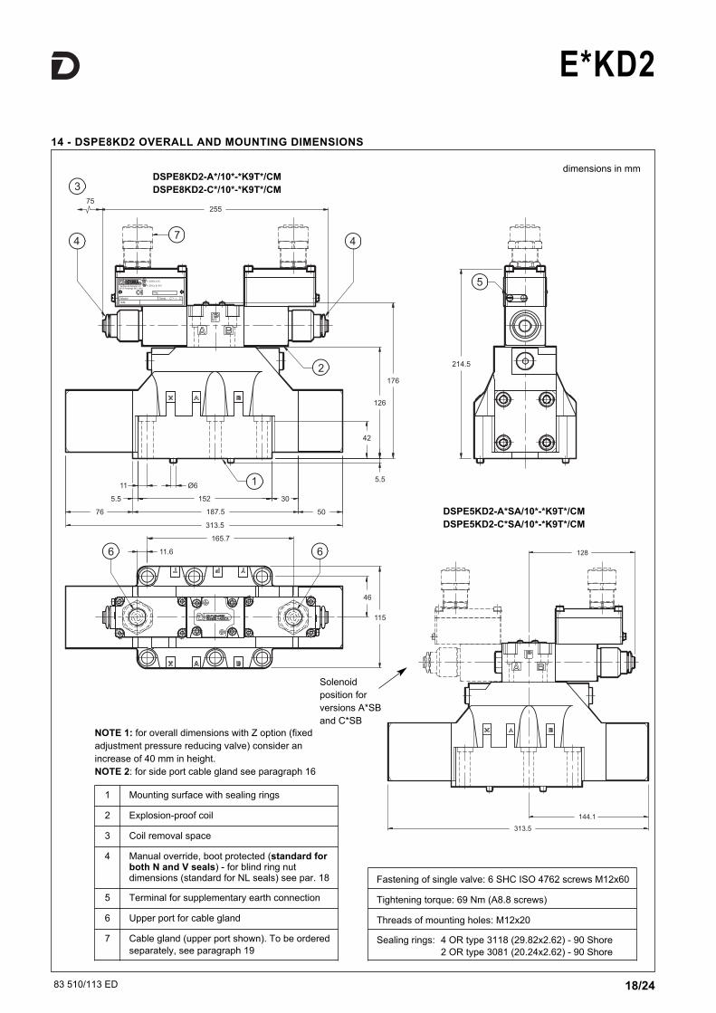
14 - DSPE8KD2 OVERALL AND MOUNTING DIMENSIONS
dimensions in mm
NOTE 1: for overall dimensions with Z option (fixed
adjustment pressure reducing valve) consider an
increase of 40 mm in height.
NOTE 2: for side port cable gland see paragraph 16
Fastening of single valve: 6 SHC ISO 4762 screws M12x60
Tightening torque: 69 Nm (A8.8 screws)
Threads of mounting holes: M12x20
Sealing rings: 4 OR type 3118 (29.82x2.62) - 90 Shore
2 OR type 3081 (20.24x2.62) - 90 Shore
1 Mounting surface with sealing rings
2 Explosion-proof coil
3 Coil removal space
4 Manual override, boot protected (standard forboth N and V seals) - for blind ring nutdimensions (standard for NL seals) see par. 18
5 Terminal for supplementary earth connection
6 Upper port for cable gland
7 Cable gland (upper port shown). To be ordered
separately, see paragraph 19
DSPE8KD2-A*/10*-*K9T*/CM
DSPE8KD2-C*/10*-*K9T*/CM
DSPE5KD2-A*SA/10*-*K9T*/CM
DSPE5KD2-C*SA/10*-*K9T*/CM
Solenoid
position for
versions A*SB
and C*SB
83 510/113 ED 19/24
E*KD2
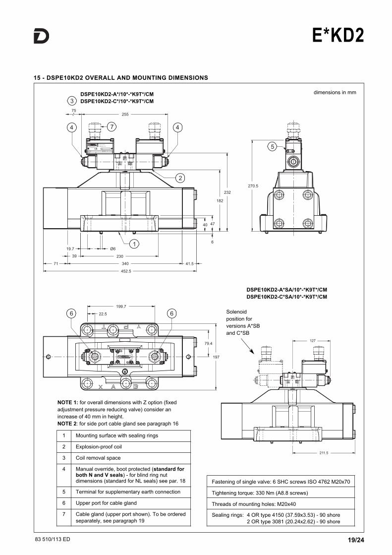
15 - DSPE10KD2 OVERALL AND MOUNTING DIMENSIONS
dimensions in mm
NOTE 1: for overall dimensions with Z option (fixed
adjustment pressure reducing valve) consider an
increase of 40 mm in height.
NOTE 2: for side port cable gland see paragraph 16
Fastening of single valve: 6 SHC screws ISO 4762 M20x70
Tightening torque: 330 Nm (A8.8 screws)
Threads of mounting holes: M20x40
Sealing rings: 4 OR type 4150 (37.59x3.53) - 90 shore
2 OR type 3081 (20.24x2.62) - 90 shore
1 Mounting surface with sealing rings
2 Explosion-proof coil
3 Coil removal space
4 Manual override, boot protected (standard forboth N and V seals) - for blind ring nutdimensions (standard for NL seals) see par. 18
5 Terminal for supplementary earth connection
6 Upper port for cable gland
7 Cable gland (upper port shown). To be ordered
separately, see paragraph 19
Solenoid
position for
versions A*SB
and C*SB
DSPE10KD2-A*/10*-*K9T*/CM
DSPE10KD2-C*/10*-*K9T*/CM
DSPE10KD2-A*SA/10*-*K9T*/CM
DSPE10KD2-C*SA/10*-*K9T*/CM
83 510/113 ED 20/24
E*KD2
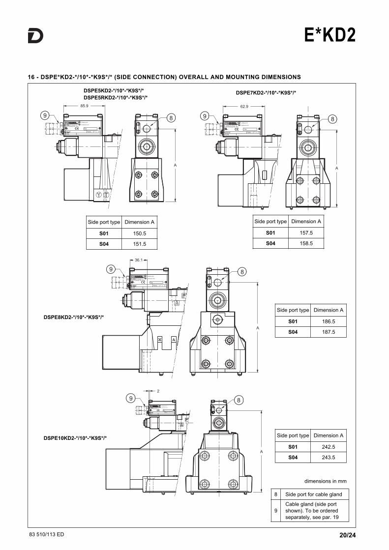
16 - DSPE*KD2-*/10*-*K9S*/* (SIDE CONNECTION) OVERALL AND MOUNTING DIMENSIONS
DSPE5KD2-*/10*-*K9S*/*
DSPE5RKD2-*/10*-*K9S*/*DSPE7KD2-*/10*-*K9S*/*
DSPE8KD2-*/10*-*K9S*/*
DSPE10KD2-*/10*-*K9S*/*
Side port type Dimension A
S01 150.5
S04 151.5
Side port type Dimension A
S01 157.5
S04 158.5
Side port type Dimension A
S01 186.5
S04 187.5
Side port type Dimension A
S01 242.5
S04 243.5
8 Side port for cable gland
9
Cable gland (side port
shown). To be ordered
separately, see par. 19
dimensions in mm
83 510/113 ED 21/24
E*KD2
0.75
T
B31.75
P
A25.915.5
5.1
12.7
31
M5
Ø4
Ø7.5 (max)Ø7.5 (max)
21.5
30.2
40.5
33
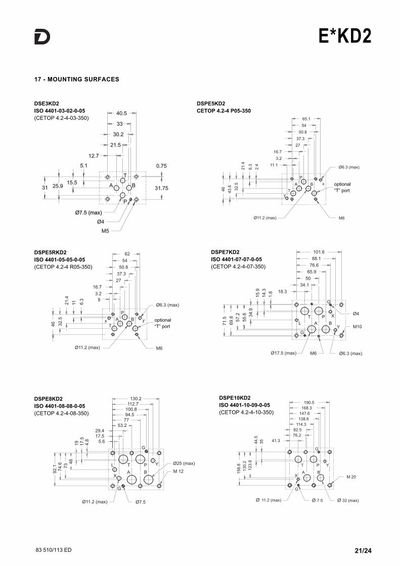
DSE3KD2
ISO 4401-03-02-0-05
(CETOP 4.2-4-03-350)
Ø6.3 (max)
attacco "T"
M6
facoltativo
54
65.1
50.8
27
37.3
B
P
A
11.1
3.2
16.7
Ty
Ø11.2 (max)
x
46
43
.6
32
.5
21
.4
6.3
2.4
54
62
50.8
y
P
B
facoltativo
M6
attacco "T"
Ø6.3 (max)8
3.2
16.7
Tx A
Ø11.2 (max)
37.3
27
46 32
.5
21
.4
11 6.3
DSPE5KD2
CETOP 4.2-4 P05-350
DSPE5RKD2
ISO 4401-05-05-0-05
(CETOP 4.2-4 R05-350)
101.6
88.1
76.6
65.9
50
34.1
Y
Ø4
M10
Ø6.3 (max)
BA
P
L
T
G
M6
X
G
18.3
Ø17.5 (max)
71
.5
69
.8 57
.2
55
.6 34
.9
15
.9
14
.3
1.6
DSPE7KD2
ISO 4401-07-07-0-05
(CETOP 4.2-4-07-350)
130.2112.7
G
Ø25 (max)
M 12
P
B
Y
Ø7.5
53.229.417.5
5.6
L
X
G
Ø11.2 (max)
A
T
7794.5100.8
92
.17
4.6
73 4
6
19
17
.54
.8
DSPE8KD2
ISO 4401-08-08-0-05
(CETOP 4.2-4-08-350)
17 - MOUNTING SURFACES
190.5
168.3
Y
G
P
76.2
114.3
82.5
T
138.6
147.6
M 20
Ø 32 (max)Ø 7.5
G
XA B
41.3
Ø 11.2 (max)
15
8.8
13
0.2
12
3.8
44
.5
35
DSPE10KD2
ISO 4401-10-09-0-05
(CETOP 4.2-4-10-350)
optional
“T” port
optional
“T” port
83 510/113 ED 22/24
E*KD2
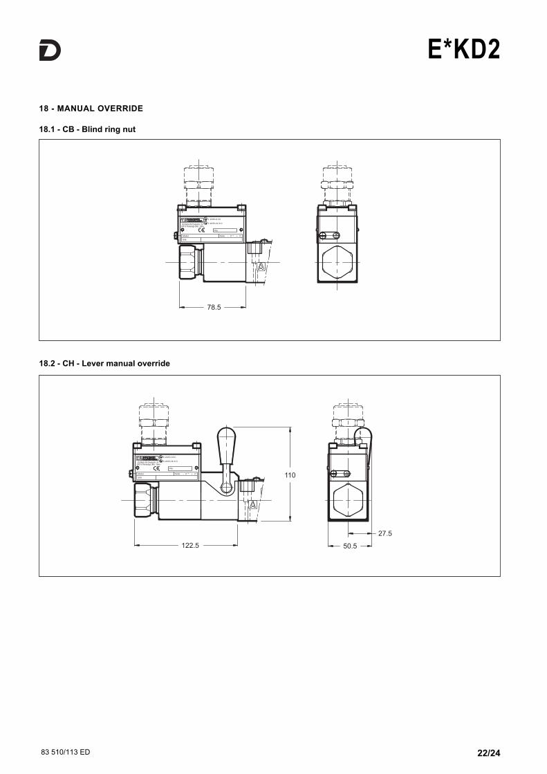
18 - MANUAL OVERRIDE
18.1 - CB - Blind ring nut
18.2 - CH - Lever manual override
83 510/113 ED 23/24
E*KD2
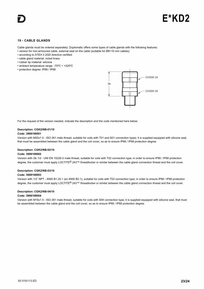
19 - CABLE GLANDS
Cable glands must be ordered separately; Duplomatic offers some types of cable glands with the following features:
• version for non-armoured cable, external seal on the cable (suitable for Ø8÷10 mm cables);
• according to ATEX II 2GD directive certified
• cable gland material: nickel brass
• rubber tip material: silicone
• ambient temperature range: -70ºC ÷ +220ºC
• protection degree: IP66 / IP68
For the request of the version needed, indicate the description and the code mentioned here below:
Description: CGK2/NB-01/10
Code: 3908108001
Version with M20x1.5 - ISO 261 male thread, suitable for coils with T01 and S01 connection types; it is supplied equipped with silicone seal,
that must be assembled between the cable gland and the coil cover, so as to ensure IP66 / IP68 protection degree.
Description: CGK2/NB-02/10
Code: 3908108002
Version with Gk 1/2 - UNI EN 10226-2 male thread, suitable for coils with T02 connection type; in order to ensure IP66 / IP68 protection
degree, the customer must apply LOCTITE® 243™ threadlocker or similar between the cable gland connection thread and the coil cover.
Description: CGK2/NB-03/10
Code: 3908108003
Version with 1/2” NPT - ANSI B1.20.1 (ex ANSI B2.1), suitable for coils with T03 connection type; in order to ensure IP66 / IP68 protection
degree, the customer must apply LOCTITE® 243™ threadlocker or similar between the cable gland connection thread and the coil cover.
Description: CGK2/NB-04/10
Code: 3908108004
Version with M16x1.5 - ISO 261 male thread, suitable for coils with S04 connection type; it is supplied equipped with silicone seal, that must
be assembled between the cable gland and the coil cover, so as to ensure IP66 / IP68 protection degree.
83 510/113 ED 24/24
! "# ! $$$%&'())'*'+,,#-%&'())'
E*KD2
REPRODUCTION IS FORBIDDEN. THE COMPANY RESERVES THE RIGHT TO APPLY ANY MODIFICATIONS.
21 - INSTALLATION
The valves can be installed in any position without impairing correct
operation.
Valve fastening takes place by means of screws or tie rods, laying
the valve on a lapped surface, with values of planarity and
smoothness that are equal to or better than those indicated in the
drawing.
If the minimum values of planarity or smoothness are not met, fluid
leakages between valve and mounting surface can easily occur.
20 - HYDRAULIC FLUIDS
Use mineral oil-based hydraulic fluids HL or HM type, according to ISO 6743-4. For these fluids, use NBR seals (code N). For fluids HFDR type
(phosphate esters) use FPM seals (code V). For the use of other fluid types such as HFA, HFB, HFC, please consult our technical department.
Using fluids at temperatures higher than 80 °C causes a faster degradation of the fluid and of the seals characteristics. The fluid must be
preserved in its physical and chemical characteristics.
22 - SUBPLATES (see catalogue 51 000)
DSE3KD2 DSPE5KD2 DSPE7KD2 DSPE8KD2
Type with rear ports PMMD-AI3G PME4-AI5G PME07-AI6G
Type with side ports PMMD-AL3G PME4-AL5G PME07-AL6G PME5-AL8G
P, T, A, B ports dimensions
X, Y ports dimensions
3/8” BSP
-
3/4” BSP
1/4” BSP
1” BSP
1/4” BSP
1 ½” BSP
1/4” BSP
NOTE: Subplates (to be ordered separately) do not contain neither aluminium nor magnesium at a higher rate than the value allowed by norms
according to ATEX directive for category 2GD.
The user must take care and make a complete assessment of the ignition risk, that can occur from the relative use in potentially explosive
environments.
Surface finishing


![Installation Manual DOPPLER SPEED LOG Model DS-80 MANUALIME72470V_DS8… · Installation Manual DOPPLER SPEED LOG Model DS-80 ... [TFB-5000 (1)] DS-782 000-029-052 1 set Gate valve,](https://static.fdocuments.us/doc/165x107/5eb632ff5abddf6851514c7b/installation-manual-doppler-speed-log-model-ds-80-manualime72470vds8-installation.jpg)