dsp_arch_past-present-future
14
DSP Architectures: Past, Present and Future* Edwin J. Tan, Wendi B. Heinzelman Department of Electrical and Computer Engineering University of Rochester Rochester, NY 14627 {etan I wheinzel)@ece.rochester. edu Abstract - As far as the future of communica- tions is concerned, we have seen that there is great demand for audio and video data to complement text. Digital signal processing (DSP) is the sci- ence that enables traditionally analog audio and video signals to be processed digitally for trans- mission, storage, reproduction and manipulation. In this paper, we will explain the various DSP architectures and its silicon implementation. We will also discuss the state-of-the art and examine the issues pertaining to performance. 1 Introduction In the last few years, the future of communica- tions has been largely influenced by the rapid growth of wireless telephony, the Internet and mobile com- puting. The traditional purposes of signal processing such as modems, music synthesis and noise cancel- lation, while important, have been overtaken by the new-found Web based applications. These emerging technologies, especially in the area of wireless com- munications and Internet audio/video, have led to a 50% increase in DSP processor shipments in 1999 [1]. As a result of this rapidly expanding market, DSP vendors are vying for an ever larger slice of the pie. To entice end product manufacturers to adopt their chips as well as to meet the needs of the emerging technologies, new innovations in DSP capabilities are required. We will look at the traditional DSP as well as the current features and the historical concepts behind the DSP architecture. Like its microprocessor counterpart, performance is of great interest. Benchmarking provides a com- mon means for DSP users to evaluate and compare DSP chips in the market. These results show that DSP processors are also bounded by tradeoffs in terms of speed, power and computational tasks. *This work was supported in part by the University of Rochester SEAS Graduate Student Fellowship No. 2-11144- 1641. 2 DSP Processor Fundamen- tals In the literature, the definition of a digital signal processor takes many forms. In a strict sense, a DSP is any microprocessor that processes digitally repre- sented signals [2]. A DSP filter for example, takes one or more discrete inputs, xi[n], and produces one cor- responding output, y[n] for n .... , -1, 0, 1, 2,..., and i = 1, ..., N [3], where n is the nth input or out- put at time n, i is the ith coefficient and N is the length of the filter. In effect, the DSP implements the discrete-time system. As its name implies, it is assumed that there must be some form of preprocess- ing if the signals are in the continuous time domain, a n d this is easily accomplished by an analog to digital converter (ADC). In general, DSP functions are mathematical op- erations on real-time signals and are repetitive and numerically intensive. Samples from real-time signals c a n number in the millions and hence a large mem- ory bandwidth is needed. It is because of this very nature that DSP processors are created with an ar- chitecture unlike those of conventional microproces- sors. Most DSP algorithms are not complicated an d only require multiply and accumulate calculations [4]. Most, if not all, DSP processors have circuitry built and hard wired to execute these calculations as fast as possible. 2.1 Processor Architectures The signal processing algorithms and functions define a suitable architecture for implementation. We use a simple example of an FIR filter as a basis for the building blocks of the DSP architecture. One algorithm used to create an FIR filter uses a direct form or tapped delay line structure with M + 1 taps. The M + 1 most recent input samples are saved as "filter states". According to Equation (1), --6m
-
Upload
sayan-ghosh -
Category
Documents
-
view
217 -
download
0
Transcript of dsp_arch_past-present-future

8/7/2019 dsp_arch_past-present-future
http://slidepdf.com/reader/full/dsparchpast-present-future 1/14
DSP Architectures: Past, Present and Future*
Edwin J. Tan, Wendi B. HeinzelmanDep artm ent of Electrical a nd Co mp uter Engineering
University of RochesterRochester, NY 14627
{etan I wheinzel)@ece.rochester.edu
A b s t r a c t - A s f a r as t h e f u t u r e o f c o m m u n i c a -t i o n s i s c o n c e r n e d , w e h a v e s e e n t h a t t h e r e i s g r e a td e m a n d f or a u d i o a n d v i d e o d a ta t o c o m p l e m e n tt e x t . D i g i t a l s i g n a l p r o c e s s i n g ( D S P ) i s t h e sc i -e n c e t h a t e n a b l e s t r a d i t i o n a l l y a n a l o g a u d i o a n dv i d e o s i g n a ls t o b e p r o c e s s e d d i g i ta l l y f o r t r a n s -m i s s i o n , s t o r a g e , r e p r o d u c t i o n a n d m a n i p u l a t i o n .
I n t h i s p a p e r , w e w i l l e x p l a i n t h e v a r i o u s D S Pa r c h i t e c t u r e s a n d i ts s i l ic o n i m p l e m e n t a t i o n . Wew i l l a l s o d i s c u s s t h e s t a t e - o f - t h e a r t a n d e x a m i n et h e i s s u e s p e r t a i n i n g t o p e r f o r m a n c e .
1 I n t r o d u c t i o n
I n t h e l a s t f e w y ea r s , t h e f u t u r e o f c o m m u n i c a -t i o n s h a s b e e n l a rg e ly i n f lu e n c e d b y t h e r a p i d g r o w t hof wi re less te lephony, the I n te rn e t and mobi le com-p u t i n g . T h e t r a d i t i o n a l p u r p o s e s o f si g n al p r o c e ss i n gsuch as modems, mus ic synthes i s and noise cance l -l a t io n , w h i l e i m p o r t a n t , h a v e b e e n o v e r t a k e n b y t h en e w - f o u n d We b b a s e d a p p l i c a t i o n s . T h e s e e m e rg i n gtechnologies , espec ia l ly in the a rea of wire less com-m u n i c a t i o n s a n d I n t e r n e t a u d i o / v i d e o , h a v e l e d t o a50% increase in DSP processor sh ipm ents in 1999 [1].
A s a r e s u l t o f t h i s r a p i d l y e x p a n d i n g m a r k e t , D S Pvendo rs a re vy ing for an ever la rger s l i ce of the p ie .To e n t i c e e n d p r o d u c t m a n u f a c t u r e r s t o a d o p t t h e i rch ips as well as to meet th e needs o f the e merg ingtechnologies , new innovat ions in DSP capabi l i t i es a rerequi red . We wi ll look a t the t rad i t io na l DS P as wella s t h e c u r r e n t f e a t u r e s a n d t h e h i s t o r i c a l c o n c e p t sb e h i n d t h e D S P a r c h i t e c t u r e .
L i k e i t s m i c r o p r o c e s s o r c o u n t e r p a r t , p e r f o r m a n c eis o f g rea t in te res t . Benc hma rking prov ides a com-m o n m e a n s f o r D S P u s e r s t o e v a l u a t e a n d c o m p a r eD S P c h i p s i n t h e m a r k e t . T h e s e r e su l t s s h o w t h a tD S P p r o c e s s o r s a r e a l s o b o u n d e d b y t r a d e o ff s i nt e r m s o f s pe e d , p o w e r a n d c o m p u t a t i o n a l t a s k s.
*This work was supported in part by the University ofRochester SEASGraduate Student Fellowship No. 2-11144-1641.
2 D S P P r o c e s s o r F u n d a m e n -t a l s
In the l i t e ra tu re , th e def in i t ion of a d ig i ta l s igna lprocessor takes many forms . In a s t r ic t sense , a DSPis any microprocessor tha t p rocesses d ig i ta l ly repre-
sen ted s igna ls [2] . A DSP f i l te r for example , t a kes oneo r m o r e d i s c r e t e i n p u t s, xi[n], a n d p r o d u c e s o n e c o r-r e s p o n d i n g o u t p u t , y[n] f o r n . . . . , - 1 , 0 , 1 , 2 , . . . ,and i = 1 , . . . , N [3] , where n is the n t h in put o r ou t -pu t a t t im e n , i is the i th coeff ic ien t and N i s thelength of the f i l te r. In e ffec t , the DS P imp leme ntsthe d i sc re te - t im e sys tem. As it s nam e impl ies , i t isa s s u m e d t h a t t h e r e m u s t b e s o m e f o r m o f p r e p r o c e s s -ing if the s igna ls a re in the co nt inuo us t ime dom ain ,an d th i s i s eas i ly accomp l i shed by an ana log to d ig i ta lc o n v e r t e r ( A D C ) .
I n g e n e r a l , D S P f u n c t i o n s a r e m a t h e m a t i c a l o p -e r a t i o n s o n r e a l - t i m e s i g n a l s a n d a r e r e p e t i t i v e a n dnum er ica l ly in tens ive . Samples f rom rea l - t ime s igna lscan n u m b e r i n t h e m i l l i o n s a n d h e n c e a l a rg e m e m -o r y b a n d w i d t h i s n e e d e d . I t i s b e c a u s e o f t h i s v e r yn a t u r e t h a t D S P p r o c e s s o rs a r e c r e a t e d w i t h a n a r -c h i t e c t u r e u n l i k e t h o s e o f c o n v e n t i o n a l m i c r o p r o c e s -s o rs . M o s t D S P a l g o r i t h m s a r e n o t c o m p l i c a t e da ndo n l y r e q u i r e m u l t ip l y a n d a c c u m u l a t e c a l c u l a t io n s [4 ].Most , i f no t a l l , DSP processors have c i rcu i t ry bu i l ta n d h a r d w i r e d t o e x e c u t e t h e s e c a l c u l a ti o n s a s f a s tas possible.
2 .1 P r o c e s s o r A r c h i t e c t u r e s
T h e s i g n a l p r o c e s s i n g a l g o r i t h m s a n d f u n c t i o n sd e f in e a s u i t ab l e a r c h i t e c t u r e f o r i m p l e m e n t a t i o n . Weuse a s imple examp le of an FIR f i l t e r as a bas i s fort h e b u i l d i n g b l o c k s o f t h e D S P a r c h i t e c t u r e .
O n e a l g o r i t h m u s e d t o c r e a t e a n F I R f i l t e r u s e s ad i r e c t f o r m o r t a p p e d d e l a y l i ne s t r u c t u r e w i t h M + 1t a p s . T h e M + 1 m o s t r e c e n t i n p u t s a m p l e s a r e s a v e das " f i l te r s ta tes" . Accord in g to Equat ion (1) ,
- - 6 m

8/7/2019 dsp_arch_past-present-future
http://slidepdf.com/reader/full/dsparchpast-present-future 2/14
M
y(n) -- ~ ~x (n - i) (1)i ----O
the product s of each filter state x(n - i) and its cor-responding coefficient ci are accumulated or addedto produce the current output sample y(n). We canalso use the signal flow graph as shown in Figure 1to repres ent this algorithm. However it is not clearas to the sequence of the computation s since it lookslike all the o perations can be carried out at th e sametime.
This cannot be the case as operations have to fol-low a sequence for proper algorithm functionality. Itis also not stated as to where the locations of the dataoperands and coefficients are before they are used inthe computations. Thus, a more accurate picture hasto be formed by using micro-operations at the regis-ter tra nsfer level (RTL), sequenced temporarily fromleft to right as seen in Figure 2 [3].
c x ~ c •t o o c
y(n)
Figure 1: T appe d delay line structur e of a FIR filter.
x(n) y(n) Inputnd utput
! '...................................................................................................................................." ~ ].'~]~ ~ ! "~] l]I~ D'!!l!ile@i!!i!
Figure 2: Register transfer level representation of aFIR filter.
The delayed inputs are stored in the da ta memory,D1 and the coefficients, Co, c l, .. . C(M) are located inthe coefficient memory. The contents of both memo-ries are fetched and multiplied together. The resultis then added to the temporary memory, T1. T1is where the results of the previous taps are stored.This cycle is rep eat ed with a different coefficient untilcompletion, producing the final result as y(n).
We can make certain assumptions for a funde-mental general purpose DSP architecture. From
our understanding of DSP algorithms, we see thatmost computations are multiply and add operations.Looking at the example from the previous section,we will require multiple memory units for storage ofdifferent data as well as memory for the arithmeticoper atio n sequences. Registers can serve as temp o-rary storage locations and buses will be needed toconnect these units together.
At this point, the reader may be tempted to askhow this design is different from a general purposemicroprocessor (GPP). If we recap th e issues centralto a DSP function, most DSP calculations are repeti-tive, require a large memory bandwidth and numericprecision, all executed in real time [5]. One mightalso argue that modern GPPs have clock speeds andcycles per intsruction (CPI) that outperform DSPprocessors but GPPs have operations and programflexibility tha t are unecessary for DSP [4]. DSPsmust execute their tasks efficiently while keepingcost, power consumption, memory usage and devel-opme nt ti me low [5], especially in the age of mobilecomputing.
Since many signal processing applications processmillions of samples of data for every second of op-eration, the minimum sample period is usually moreimportant than the computational latency of the pro-cessor [3]. We define the sample period as the timebetween each sequential sample of the input data.The time difference between the input dat a a nd theresult of its computation is known as the computa-tional latency. Once the initial sample is calcula ted
with a certain latency, the subsequent results willhowever, be produced at t he sample period rate. Asthe number of calculations increases, the relativelylarger late ncy of the p rocessor will be negligible com-pared to the sample rate.
3 P r o c e s s o r E v o l u t i o n
Even though DSP processors have seen dramaticchanges through the past couple decades, there arecertain features central to most DSP processors in the
market today. We already know tha t these proces-sors need multiple memory banks with independentbuses, but in addition, specialized instruction sets,addressing modes, control and peripherals are alsorequired.
It is widely known in the industry t ha t the generalDSP architectures can be divided into three or fourcategories or generations [5] [6] and we will look ateach of them in turn. We will not address customDSP architectures for specific DSP algorithms in thispaper.

8/7/2019 dsp_arch_past-present-future
http://slidepdf.com/reader/full/dsparchpast-present-future 3/14
3 .1 E a r l y Si n g l e C h i p D S P P r o c e s s o r s
The first single chip processors [7] were the foun-dation on which modern DSP processors were built.Although most of them were not commercially suc-cessful, manufa cture rs were quick to learn t he pitfallssurrou nding each of them. It is also interesting tonote that among these early chip vendors, only onehas maintained a DSP product line to this day.
In 1978, AMI released a "Signal Processing Pe-ripheral" known as the $2811 which was designedto operate along with a GPP such as the 6800 fromMotorola. The $2811's main function was to relievethe burden of performing math intensive subroutinesfrom the main processor. In short, it behaved as amath coprocessor and was never used in large quan-tities in any end product.
A year later, Intel announced an "Analog SignalProcessor" which had an analog to digital converter(ADC) and digital to analog converter (DAC) re-siding on the die. The disa dvantag e of this proces-sor, 2920, was that it did not have a true multiplier.Multiplication was accomplished by bit shifting andadding partial products; thus the performance of the2920 was only silghtly better than a GPP. Commer-cially, the chip was only used in modems.
AT&T's Bell Laboratories introduced the DSP1 inFebruary of 1980. The DSP1 had most of the func-tional un its seen in curren t DSP processors such as amultiply and accumulator (MAC), parallel address-ing unit, control and data memories. Its success wasalso due to t he fac t th at development tools were avail-able for rapid prototyping. The DSP1 architectural
heritage has survived until today, evolving into theDSP 1600 processor f amily from Lucent Technologies.
3 . 2 F i r s t G e n e r a t i o n C o n v e n t i o n a l
This class of architecture represented the firstwidely accepted DSP processors in the market, ap-pearing in the early 1980's. There were a fewkey manufacturers tha t offered processors that shareman y similar traits. The chips were designed aroun da Harvard architecture with separate data and pro-gram buses for the individual data and programmemories respectively. The key function al blockswere the multiply, add and accumulator units, butthese processors could only perform fixed-point com-putations. The software tha t accompanied the chipshad specialized instruct ion sets and addressing modesfor DSP with h ardware su ppor t for software looping.
These processors were the TMS320C10 from TexasInst rumen ts and t he ADSP-2101 from Analog De-vices. A graphical representa tion of the general ar-chitecture is depicted in Figure 3.
Programmemory
r
Figure 3:tecture.
Program us
Data bus
Data ] Mmemory
Control " I
JFirst generation conventional DSP archi-
3 . 3 S e c o n d G e n e r a t i o n E n h a n c e dC o n v e n t i o n a l
The next stage of development started in thelate 1980's/ear ly 1990's, and variant s of this architec-ture have lasted until today. These processors retainmuch of the design of the first generation but withadded features such as pipelining, multiple arithme ticlogic units (ALU) and accumulators to enhance per-formance. The advantage in this is that most pro-cessors are code compatible with their predecessorswhile providing speedup in operations.
Shrinkage of feature sizes also allowed more func-tional units to be included on the chip. Peripheraldevice interfaces, counters and ti mer circuitry, impor-tant to da ta acquisition, are now incorporated in thesame die as the DSP. In addition, parallelism couldbe atta ined by duplicating key functional units.
The TMS320C20 from Texas Instruments com-bines both a pipelined architecture and an Auxil-Iary Register Arithmetic Unit (ARAU). In ad dition,the on-chip data RAM can be configured either asdata or program memory. The ARAU can provideaddress manipulation as well as compute 16-bit un-signed ari thmetic , off-loading some o f the processingfrom the Central Arithmetic Logic Unit (CALU) [8].
Another example from this era is the MotorolaDSP56002. It has a three-s tage pipeline and pe-ripherals such as a Serial Communications Inter-face (SCI), Synchronous Serial Interface (SSI), Paral -lel Host Interface, Timer/Event Counter and PhaseLock Loop (PLL). There are three RAMs, one forprogram an d storage and two for data. A 24 by 24-bit multiplier is accompanied by two 56-bit accumu-

8/7/2019 dsp_arch_past-present-future
http://slidepdf.com/reader/full/dsparchpast-present-future 4/14
lators [9].The latest Lucent Technologies' fixed point
DSP16xxx fa mily of processors looks very much likeits predecessor introduced in 1990, the DSP1600. Itsenhancement is in its data path, which includes two16 by 16-bit multipliers, an additional 3-input adderand eight 40-bit accumulators [10]. The simplified
data path is shown in Figure 4 for comparison witha tra diti onal DSP archite cture [10] [11]. Ignoring theshifters and swap/split multiplexers, the basic dataflow of the multiplier, ALU and accumulator is con-ventional.
. • y(32) x(32)
swap multipl .. . /
I I16 x 16 multiply [ I 15 x 16 multiplyI I
iift_, +
bit 3 input adder~_~ manipulation
unit
split/multipl .. . /
8 x 40 b it accumulator
i l l lFigure 4: Simplified Lucent Technologies DSP16xxxdata path.
3 . 4 T h i r d G e n e r a t i o n N o v e l D e s i g n s
It is about this time that designers were lookingat incorporating GPP architectures into DSPs. Thisspeeds up computations while retaining the func-tions critical to DSP. Today' s DSPs execute single in-struct ion multiple data (SIMD), very long instruc tionword (VL1W) and superscalar operations. On thesoftware side, more advanced debugging and appli-
cation development tools have been created to com-plement multiple instruction hardware loops, moduloaddressing and user defined instructions [5].
SIMD is characteristic of most high performanceGPPs tha t are also capable of multimedia extensions(MMX) and AltiVec algorithms. SIMD allows one in-struction to be executed on many independent groups
of data. For SIMD to be effective, programs and dat asets must be tailored for data parallel processing, andSIMD is mo st effective with large blocks of da ta [5].In DSP, SIMD may require a large program memoryfor rearranging data, merging partial results and loopunrolling. The two common ways of implementin gSIMD are to use split execution units and multipleexecution units or data paths depicted in Figure 5[5].
32-bit x input register
16bits I 1
32-bit y input register
16 bits 16 bits
I functional units
~its
32-bit output register with two 16-bit results
Figure 5: SIMD split execution unit data path.
VLIW processors issue a fixed number of instruc-
tions either as one large instruction or in a fixed in-struction packet, and the scheduling of these instruc-tions is performed by the compiler [12]. For VLIWto be effective, there must be sufficient parallelism instraight line code to occupy the operation slots. Par-allelism can be improved by loop unrolling to removebranch in structio ns and to use global scheduling tech-niques, but t hen a disadva ntage of VLIW is low codedensit y if loops canno t be sufficiently unrolled.
Superscalar processors, on the other hand, can is-sue varying numbers of instructions per cycle andcan be schedulled either st atical ly by the compiler ordynami cally by the processor itself [12]. As a re sult,
superscalar designs may hold a couple of code densityadvantages over VLIW. This is because the proces-sor can determine if the subsequent instructions in aprogram sequence can be issued during execution, inaddition to running unschedulled programs.
Recently, we have seen that VLIW has been regain-ing popularity as a means to improve performance.The latest instruction set architecture co-developedby Intel and Hewlett-Packard, the IA-64, retainsmuch of the VLIW flavor with nuances of CISC and
- - 9 - -

8/7/2019 dsp_arch_past-present-future
http://slidepdf.com/reader/full/dsparchpast-present-future 5/14
RISC [13]. This hybrid architecture is called explic-itly parallel instruction computing (EPIC) and itsmain purpose is to permit the compiler to group in-structions for parallel execution in a flexible fash-ion. This VLIW-like concept has also been portedto the DSP domain. The joint-venture between Mo-torola and Lucent Technologies, StarCore, has an-nounced a new DSP architecture known as variablelength execution sets (VLES). Like EPIC, VLEScombines CISC, RISC and traditional VLIW into anarchitecture tha t tries to eliminate VLIW's two ma-jor disadvan tages: code density and code scalabil-ity/co mpatib ility [14].
The latest DSP chip family from Texas Instru-ments, TMS320C64x, combines both VLIW andSIMD into their architecture known as VelociTI.2.Instead of varying the length of instruction groups asin EPIC and VLES, this scheme improves the perfor-mance o f VLIW by allowing execution packets (EP)to span across 256-bit fetch packet boundaries [15].Each EP consists of a group of 32-bit instructionsand th e EP can vary in size as seen in Figure 6. By
removing these boundaries, no operation (NOP) in-structions, common in traditional VLIW, are elimi-nated and code size is minimized [16].
I I I I I I I I I9 ~
EP I
I I I I I I I I IEP2 EP3
I I i l 11111EP3 EP4 EP5
9 iP
256 bits
Figure 6:VelociTI.2 architecture allowing boundary-less EP.
The VelociTI.2 architecture implements the SIMDphilosophy in providing two register file data crosspaths [15]. Each data path includes a general pur-pose register file and can be used for either data, da taaddress pointer s or condition codes. The cross paths,1X and 2X, allow functional units from one side toaccess a 32-bit operand from the register file of theother side. This access can be performed simultane-ously while the other side's functional units are usingoperand s from its register file. Figure 7 is a simpli-fied diagram of the 'C64x dat a cross paths. The eightfunctional units are L1, L2, S1, $2, M1, M2, D1 andD2. DA1 and DA2 are the d at a address paths.
The debate between the merits of superscalar and
VLIW is not only restricted to the GPP universe. LSILogic Corp. prefers the superscalar approach and iscurrently the major manufacturer to champion thisarchitectur e. We know tha t a key difference betweensuperscalar and VLIW lies in the hardware and soft-ware complexity respectively. The arg umen t pre-sented by LSI Logic is that the VLIW methodologyrequires a greater programming effort and is at themercy of the compiler. A change in the processorhardwar e will also require a correspondin g change inthe compiler to preserve efficiency [17].
It is also common in DSP programming to handcode assembly code instructions for optimization, es-pecially in loop operations. However, because ofVLIW's bundling of instructions, it is difficult forprogrammers to track the multiple instructions fordifferent functional units in a deeply pipelined struc-ture. The ZSP architecture from LSI Logic, real-ized as the ZSP16400, intend s to reduce progr am-ming and compiler complexity without loss of per-formance by implementing hardware techniques. Inaddition to adopting a five stage pipelined architec-
ture, the superscalar ZSP16400 can issue up to fourinstruct ions per cycle to two MACs and ALUs. Manyof the other features are almost identical to a GPP;a one cycle RISC instruction set, l oad/s tore architec-ture, fixed length instructions and hardware schedul-ing [18]. The ZSP processor architecture is shown inFigure 8 [18].
3 .5 P o w e r C o n s i d e r a t i o n s
Power has been a major concern lately with in-creased use of DSPs in mobile computi ng. Fortu-nately, the arch itectu ral concepts we discussed in thissubsection help to play a part in reducing power con-sumption . Power dissipation is lowered as parallelismis increased with the use of multiple functional unitsand buses. As a result, power usage is reduced whenmemory accesses is minimized [19].
Increasing the word size as well as implement ing aVLIW-like algorithm allows more d ata to be fetchedper cycle and improves code density. An opti mumcode density saves power by scaling the instructionsize to just the required amount. This is the basicidea of a variable length instruction set processor.The burst-fill instruction cache in the Texas Instru-ments' TMS320C55x family is flexible enough to beoptimized based on the code type. This mechanismimproves the cache hit ratio and reduces memoryaccesses. The core processor can also dyna mical lyand independently control the power feeding the on-chip peripherals and memory arrays. If these arraysand peripherals are not used, the processor switchesthem to a low power mode and brings them back to
10

8/7/2019 dsp_arch_past-present-future
http://slidepdf.com/reader/full/dsparchpast-present-future 6/14
I Sl $2 DLI
register A0 - A31 2X
DAI(address)
IX
DA2(address)
register B0 - B31
Figure 7: Simplified diagram of the 'C64x data cross paths.
J!
~ 2X
intermpt input, . . . . . . . . . . . . . . . . . . . . . . . . . . . . . . . . . . ~. . . . . . . . . . . . . . . . . . . . . . .
Intearupt Control
: : ! : ' : : i Instruction _ _ Pipel :ne I < = l ~luacne , Unit - - Cont rol T
-; 2: :: Data : . Bo~,~ 2 2
. . . . . . . . . . . . . . . . . . . . . . . . . . . . . . . . . . . tL . . . . . . . . ~ ? Z Z i ' i . . . . .
Figure 8:ZSP16400 processor architecture.
11

8/7/2019 dsp_arch_past-present-future
http://slidepdf.com/reader/full/dsparchpast-present-future 7/14
full power when an access is initiated without anylatency [19]. Another feature unique to this DSPprocessor is tha t the CPU, DMA, peripherals, exter-nal memory interface (EMIF), instruction cache andthe clock generator can be switched to a low activityI D L E mode using user controllable software.
We cannot neglect the effects of CMOS process
technologies. Motorola's HIP-6 or Lucent's COM20.18 micron process will be used to fabricate Star-Core's SC140. The six layer copper interconnectchip's core is estimated to draw 198 mW at 1.5 Vand 300 MHz and 28 mW at 0.9V and 120 MHz with3000 raw MIPS [14]. As a compariso n, the 'C5 5x coreconsumes between 11.2 and 64 mW at 1.2/1.5 V andbetween 7 and 40 mW at 0.9 V. However, the 'C55xcan only compute between 140 and 800 MIPS [20].In summary, the low voltages are especially impor-tant as power consumption is defined by the produc tof load capacitance, voltage squared, transition fre-quency an d clock frequency.
3 . 6 F o u r t h G e n e r a t i o n H y b r i d s
The distinction between a true DSP prod uct and acompu ter is getting fuzzier, and each day a larger per-centage of interne t traffic is composed of audio andvideo data. The problem lies in processing the audioand video at the users' end. Here lies the dilemma;the need for signal processing in a computer basedenvironment, sometimes simultaneously with generalpurpose computing. Or in other cases, to be capableof processing some digital signals but not wanting to
incur the ex tra cost of a dedicated DSP chip. Devicessuch as the se proc ess control signals as well as digitaldata.
Instead of a DSP core, the hybrids in the mar-ket now incor porate DSP circuitry with a CPU core.A positive side effect is that printed circuit board(PCB) real estate is saved, thereby reducing the sizeof the prod uct, costs and more importantly the realsavings in the power consumed. In the hy brid proces-sor, the GPP instruction set is retained and the ad-ditional DSP instructions offioad the processing fromthe GPP core.
The first commercially marketed hybrid, the Hi-
tachi SH-DSP is geared towards cellular applicationsand control intensive DSP products such as diskdrives and modems [21]. The SH-DSP is actually acombination of two cores, the SuperH RISC proces-sor and the DSP core with on-chip peripherals suchas timers, communications interfaces, I/O and mem-ory controllers [22]. It is interesting to note tha t theRISC core implements the yon Neumann a rchitecturewhile the DSP is Harvard. Integer MAC operationsare carried out by th e RISC core while the DSP core
processes the more complex DSP instructions. Bothcores are fed from a loa d-store five-stage pipeline a ndboth general purpose and DSP instructions can be inthe same instruction stream.
The I, X, Y and Peripheral buses are the four in-ternal buses with which the cores communicate withthe memories and peripheral devices. The I bus is
comprised of a 32-bit address and data bus knownas the IAB and IDB respectively. This bus is usedby both the RISC and DSP core to access any mem-ory block, i.e., X, Y or external . Th e X and Y busis only accessible to th e DSP core for the on-chip Xand Y memories, and each bus has a 15-bit addressbus and 16-bit data bus. This address bus is actuallypadded with a zero in the LSB position since mem-ory accesses are aligned on word lengths. Lastly, thePeripheral bus transmits bidirectional data to the Ibus via the Bus State Controller (BSC) [22]. Figure9 presents a simplified block diagram of the SH-DSParchitecture. The DSP enhanced RISC core is repre-sented by the Integer Unit.
24kB ROM I4kB RAM) [
I bus
Y bus
X bus
I II I
I,CPU
~ Periphera|Units
Peripheralbus
Figure 9: Simplified SH-DSP family processor archi-tecture.
The latest hy brid design comes from Motorola, us-ing their MoCore RISC microcon troller unit (MCU)core in conjunction with a DSP56600 DSP core. Th egeneral idea is similar to the SH-DSP in which thehardware architecture is intended for cellular appli-ances. Both RISC cores are load-store, pipelined andrequire a single cycle to execute most instructions.The MoCore is a 32-bit processor but its instructionsare 16-bit in length so as to reduce power consump-tion as well as cost [23]. The DSP core has only one
12

8/7/2019 dsp_arch_past-present-future
http://slidepdf.com/reader/full/dsparchpast-present-future 8/14
16 by 16-bit MAC but incorporates nested hardwarefor do loops [24]. In addition to MCU/DSP sharedperipherals, the newest member of the DSP566xxfamily, the DSP56690, has many application spe-cific DSP peripherals such as a baseband port in-terface, serial audio codec port, Viterbi acceleratorand layer-1 encryption. These embedded features are
designed to support the most common wireless pro-tocols in use today; GSM, CDMA, TDMA, iDEN,GPRS [25]. To reduce die size and power consup-tion, the chips will eventually be manufactured inMotorola's HiPerMOS-6 (HIP-6) 0.18 micron tech-nology.
3 . 7 N e x t G e n e r a t i o n s
Based on the current trends seen in DSP devel-opment, we can predict that the manufacturers willbe following the p ath of GPP techniques. We havealready seen that superscalar, VLIW and pipeliningarchitectural methods, common in GPP, are in usein the latest DSP processors. Process technologiessuch as copper interconnect and submicron featuresize will reduce chip area to enable smaller handhelddevices. Since 1985, ther e has been an increase ofalmost 150% in DSP processor performance and thistrend will certainly continue for the next few years[5].
This means th at we can expect to see more on-chipperipherals and memory; the system-on-chip (SOC)may n ot b e to o far away. Clock speeds will increaseto reduce MAC computation times, but supply volt-age must also correspondingly drop to reduce powerconsum ption. In Section 5 of this pap er, we will lookat a few potential techniques currently developed forGPP that we think may be adopted or modified foruse in DSP.
3 . 8 P r o d u c t C o m p a r i s o n s
In any study or evaluation, the inevitable ques-tion arises; which is the best? We will not at tem pt toanswer the question but leave this as topic of discus-sion for the reader. Like in GP P studies, there aretradeoffs to be made and perhaps there is no clear
choice. Perh aps anothe r way of presenting this ques-tion is how to select the right DSP processor for eachspecific need, since one may be best suited for a par-ticular application but be a poor choice for anotherpurpose [26].
We first consider the arithmetic format since themain purpo se of a DSP is to process numerical data.DSPs can be classified into one of two types; fixedor floating point. Most general DSPs are fixed poin tsince the circuitry is easier to design and manufac-
ture. Data widths of fixed point processors are alsosmaller than floating point, generally 16-bits as com-pared t o 24-bits respectively. Thus fixed point DSPsare cheaper and consume less power than their float-ing point counterparts and are usually used in highvolume, compact sized, low power embedded appli-cations. However, floating point devices are easier
to program since floating point arithmetic has moreflexibility and a larger dynamic range. The dynamicrange is the ratio between the smallest and largestnumbers that can be represented. A fixed point pro-gram has to be carefully scaled by the user so as topreserve the numeric precision required within thetighter dynamic range.
Speed is a number that tends to get every-one's attention, and the most common numberquoted for processors is the clock rate specified inmega/gigahertz . The clock cycle is then the inverseof clock rate. However, it is incor rect just to com-pare performance purely on this figure as the workdone per clock cycle by each processor can vary, eventhough a significantly high clock rate can o utperf orman efficient lower clock rat e processo r. A rela ted met -ric that is frequently quoted is MIPS or millions ofinstructions per second. The problem with MIPSis that it is dependent on the instruction set [12][26]. The VLIW DSP processors issue and executemultiple simple instructions per cycle and these sim-ple instructions typically perform fewer operationsthan conventional DSP instructions. Anothe r com-mon DSP function is multi-bit data shifting whichsome processors can implement with a single instruc-tion while others may require multiple one-bit shiftinstructions. Speed and performance is a topic oftendebated and we will revisit this issue again in thebenchmarking discussion.
We present a case study [27] to illustrate thesetradeoffs. Texas Instruments has released their lat-est DSP processors at about the same time, but eachfrom a different family line tailored to meet specificneeds. Th e 'C6000 family is optim ized for the h ighestperformance in terms of speed an d simplicity in pro-gramming with a high-level language. On the o therhand, the 'C5000 family was designed to operate onvery low voltages and power con sumptio n. This is to
target the consumer digital market and battery pow-ered mobile products, whereas the 'C6000 is bettersuited for network communications tha t are poweredby fixed line supplies. Some of these appli cation sare modems, wireless base stations and machine vi-sion systems. Architecturally, the 'C6000 incorpo-rates many new techniques such as VLIW and spe-cial purpose instructions. This family is rated up to8800 MIPS at 1.1 GHz. The 'C5000 is an enhancedconventional processor with an additional ALU and
13

8/7/2019 dsp_arch_past-present-future
http://slidepdf.com/reader/full/dsparchpast-present-future 9/14
MAC and will deliver between 140 and 800 MIPSwhile running on 0.9 V. This study shows that thepowe r/perfo rmanc e tradeoff is still a real issue tha thas not been solved.
4 B e n c h m a r k i n g D S P
As in GPP, DSP users need a basis to compareperformance. This being said, benchmarking is notan easy task as there are many factors to consider.Like microprocessors, DSP performance is not gov-erned b y just one factor b ut a series of specificationssuch as power, clock speed, word size, etc. Combina-tions of these factors may suit a particular applica-tion and not another [28].
Currently as well as in the past, the popular met-ric for quoting DSP performance is MIPS. How-ever~ MIPS is not clea r as to what an y proces-sor is good at for the reasons we have already dis-cussed. As a result, the GPP and computer commu-nity founded Standard Performance Evaluation Cor-poration (SPEC) in 1988 to develop a realistic setof standardized tests for rating computing systems[29]. SPEC is a suite of C language program frag-ments, applications and kernels that can be run oncompu ter systems. The m ain advan tage of suite test-ing is that the negative effect of one benchmark isoffset by the rest of the programs in the suite [12].Unfortunately, executing SPEC benchmarks on em-bedded and DSP processors would also be unrealisticas the SPEC suite of programs are general in natureand are not tailored for DSP. Also, it is common to
manually code sections of DSP algorithms in assem-bly for optimum performance because C complilersare inefficient in translating C code to DSP assembly[2].
It is this reason that in 1994, an independentDSP technology analysis and software developmentfirm, Berkeley Design Technology, Inc. (BDTi), de-veloped a set of DSP algorithm kernel benchmarks[30]. These algorithm kernels are implemented inhand optimized assembly and so are not architecturedependent. It is even possible to run these bench-marks on GPPs for comparison with DSP proces-sors. Unlike SPE C, BDT i implemen ts and verifies
these benchmarks but will publish these results ontheir web site without charge.
BDTi's concept is to strictly define these bench-marks and to allow only realistic optimizations.These ben chmarks axe described in Table 1 [2]. Thealgorithm optimiz ations are firstly for speed and the nmemory use except for the control benchmark inwhich memory is optimized first.
The results of the benchmarking can be presentedin terms of cycle counts or execution time and BDTi
Function Description
Real Block FIR Finite impulse filter op-
erating on real data.
ComplexFIR
Block FIR filter opera ting oncomplex data.
Real Single SampleFIR
FIR filter operating onsingle sample of realdata.
LMS Adaptive Fil-te r
Least mean square adap-tive filter operating onsingle sample of realdata.
Two-Biquad IIR Infinite impulse responsefilter operating on singlesample of real data.
Vector Dot Pr od- Sum of pointwise multi-uct plication of two vectors.
Vector Add Pointwise addition of twovectors resulting in thirdvector.
Vector MaximumLocate the value of themaximum vector.
Viterbi Decoding Decode a block of convo-lutionally encoded bits.
256-Point-In-PlaceFFT
Fast Fourier transform toconvert time domain sig-nal to frequency domain.
Bit Unpack Unpack variable lengthdata from a bit stream.
Control Sequence of control op-erations e.g. test, pop,push, branch and bit ma-nipulation.
Table 1: BDTi benchmark suite.
1 4 - -
8/7/2019 dsp_arch_past-present-future
http://slidepdf.com/reader/full/dsparchpast-present-future 10/14
has chosen the latter in their reports. In some cases,a single numerical figure is required for quick com-parison and BDTi has formulated a score known asthe BDTImark2000, based on their application ker-nels suite. The BDTImark2000 represents DSP speedand so a higher figure denotes better performance.The limitation of this score is that it is only an es-
timate of the processor's execution speed and not ofspecific applications. Hence a processor's strength ina particular application may not be reflected in itsBDTImarks score [31]. Energy consumption is ob-tained by multiplying the typical power usage of theprocessor by the execution time of a benchmark. Al-though it may be a less accurate method, it is lesstime consuming and easier to implement [2].
Another aspect of characterizing performance byBDTi is appli cation profiling. The results give a bet-ter picture of how kernels are actua lly used in applica-tions. Essentially, profiling calculates the executionfrequency of kernels in applications and it presentsdevelopers the relative weightings of each algorithmkernel benchm ark in a certain application. The com-parisons between processors can be made by com-paring the product of kernel execution times and itsnumber of occurences in the application.
Recently a p ath taken by the industry was to fol-low in the footsteps of SPEC. In April of 1997, aconsorti um of 21 manufacture rs led by a tra de publi-cation, Electronic Design News (EDN), star ted workon a new set of benchmarks targ eted towards embed-ded processors. This group is formally known as theEDN Embe dded Microprocessor Benchmark Consor-tiu m (EEMBC), pronounced as "embassy". Theiraim was to develop a group of tests that can be eas-ily ported to different processor architectures, hard-ware platforms and operating systems while mea-suring specific areas of the processor's performanceindependently [32]. The benchmark scores are re-ported individually for each test, unlike SPECint95or SPECfp95 [33]. However, EEMBC also providesa single composite scores for faster comparisons be-tween processors. This score is determined by as-signing a weight to each of the t est in t he suite. TheEEMBC composite scores are created for each of thefive application tes t suites, for example, the compos-
ite score for telecommunications is called Telemark,and for networking, Netmark.The EEMBC suite of tests are written in ANSI C
for portabi lity and are similar to BDTi's idea of algo-rith m kernels. Since the embedded market is diverse,the benchmark algorithms are divided into five cat-egories so as to allow testers to quantify their prod-ucts with relevant tests, but there is nothing prevent-ing testers to run their processors on other test cat-egories. These five areas are automotiv e/ind ustr ial,
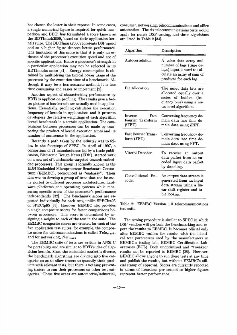
consumer, networking, teleco mmunicatio ns and officeautomation. The six telecommunications tests wouldapply for purely DSP testing, and these algorithmsare listed in Table 2 [34].
Algorithm Description
Autocorrelation A voice data array andnumber of lags (time de-lays) input is used to cal-culate an arr ay of sum ofproducts for each lag.
Bit Allocation The input data bits areallocated equally over aseries of buffers (fre-quency bins) using a wa-ter level algorithm.
Inverse FastFourier Transform(iFFT)
Converting frequen cy do-main data into time do-main data using iFFT.
Fast Fourier Trans-form (FFT)
Converting frequency do-main data into time do-main data using FFT.
Viterbi Decoder To recover an outputdata packet from an en-coded input data packetby decoding.
Convolu t iona l En-coder
An output dat a stream isgenerated from an inputdata stream using a lin-ear shift register and ta-ble lookup.
Table 2: EEMBC Version 1.0 telecommun icationstest suite.
The testing procedure is similar to SPEC in whichDSP vendors will perform the benchmarking and re-port the results to EEMBC. It becomes official only
after EEMBC verifies the results with the identi-cal test parameters used by the manufacturers inEEMBC's testing lab, EEMBC Certification Lab-oratories (ECL). Both unoptimized and "tweaked"results can be reported to EEMBC [28]. However,EEMBC allows anyone to run these tests at any timeand publish the results, but without EEMBC's offi-cial stamp of approval. Scores are cu rrent ly repor tedin terms of iterations per second so higher figuresrepresent better performance.
15

8/7/2019 dsp_arch_past-present-future
http://slidepdf.com/reader/full/dsparchpast-present-future 11/14

8/7/2019 dsp_arch_past-present-future
http://slidepdf.com/reader/full/dsparchpast-present-future 12/14
m
MIPSffunction
Evaluatin g thmc diffcrcnt DSP processors tbr a modem appli cation
Figure 10: Th e Luce nt Technologies Applications Cube.
Manufactur er Processor Family Speed (MHz) 1 Architecture MIPS 2 BDTImark 2000
Texas Instrumen ts TMS3 20Cl x 20 conventional 8.77 n/ a
Hitachi SH2-DSP 100 hyb rid 1003 280
Moto rola DSP563 xx 150 hybr id 150 450
Analog Devices ADSP-2 1xx 754 conven tional 75 230
Texas Instr ume nts TMS320 C54xx 160 enh. conventio nal 160 500
Luce nt Technologies DSP16 xxx 170 enh. conventio nal 1705 810
LSI Logic ZSP164x x 200 supersca lar 400 n /a
Texas Inst rume nts TMS320 C62xx 300 VLIW 2400 1920
Table 3: Comparison of bench mark scores for fixed point commercial DSP processors.
in a DSP processor. Most DSP operations can besimplified into multiplications and additions, so theMAC formed the main functional unit in early DSPprocessor. Designers later incorpora ted techniquesfrom GPPs to enhance the performance of DSPs.These architectures included pipelining, VLIW, su-perscalar, and although not discussed in this paper,branch p rediction and speculation. These ideas willstay with DSP processors and we think that the dif-ferences between the DSP and G PP will become moreblurred in the future.
There has been a drive to develop new benchmark-
lInstruction clock speed for fastest device in the family2MIPS for corresponding device speed3Assuming one instruction per clock cycle4Input clock is 37.5 MHz510 ns multiply and accumulate instruction cycle ime
ing schemes to measure performance since MIPS isbecoming less acccepted as a reliable metric. We seetwo different groups taking an identical approach byusing application kernels and a commercial vendorthat also measures performance in terms of powerconsumption, performance and cost. Power issues aregaining importance as DSP processors are incorpo-rated into handheld, mobile and wireless devices. Fi-nally, we discussed techniques such as asynchronousdigital circuits and wave-pipelining that could be ex-ploited in the future for performan ce as well as powerawareness.
17

8/7/2019 dsp_arch_past-present-future
http://slidepdf.com/reader/full/dsparchpast-present-future 13/14
7 A c k n o w l e d g m e n t s
The authors would l ike to tha nk Dr. StephenMcAleavey for his t ime and effort in directing theauthors to relevant sources of DSP material and forhis insights into the subject.
[13]
[14]
R e f e r e n c e s [15]
[1] Forward Concepts, "Forward Co ncepts DSPMarket Bul le t in" , World Wide Web, h t tp : / / [16]w w w . f o r w a r d con ce p t s . com / p r e s s 2 5 . h t m , 7 t hA p r . 2 0 0 0 .
[17][ 2] B e r k e l e y D e s i g n Te ch n ol o g y , In c. , " E v a l u -
a t i n g D S P P r o ce s s o r P e r f or m a n ce " , W o r l dW i d e W e b , h t t p : / / w w w , b d t i . cor n / a r t i cl e s /b e n c h m k _ 2 0 0 0 , p a l , 2 0 0 0 . [ 18 ]
[3] V. K. Madisetti, VL SID igital Signal Processors:A n Introduction to Ra pid Prototyping and De-
sign Synthesis, Boston, MA: Butterworth Heine-ma nn , 1995. [19]
[4] J. S. Thompson, S. K. Tewksbury, "LSI SignalProcessor Architecture for Telecomm unications [20]Applications", IEEE Transactions on Acoustics,Speech, and Signal P rocessing,Vol ASSP-30, No.4, pp. 613-631, Au g 1982. [21]
[5] Berkeley Desig n Technology, Inc., "Th e Evo-lution of DSP Processors", World Wide Web,h t t p : / / w w w . b d t i . c o m / a r t i c l e s / e v o l u t i o n . [ 2 2 ]p d f , 2 0 0 0 .
[6] L. G eppert , "High-Flying DSP Architectures", [23]IEEE Spectrum, pp. 53-56, Nov 1998.
[7] J. R. Boddie, "The First Single-Chip DSP",World Wide Web, h t t p : / / ww w, lu ce nt , corn/ [24]m i c r o / d s p / s i n g l e . h t m l , 2 0 0 0 .
[8] Texas Instru men ts, Inc. TMS3ZOC2x User 's [25]Guide, Austin, TX, Jan 1993.
[9] Motorola, Inc. DSP 56002 Technical Data, Rev.3, AZ, 1996. [26]
[10] J. Bier, "DSP16xxx Targets Communications
Apps", Microprocessor Report, Vol. 11, No. 12,pp. 11-15, Sep 1997.
[11] Lucent Technologies, Inc., DSP16000, Allen- [27]town, PA, Sep 1997.
[12] J. L. Hennessy, D. A. Patterson, Computer Ar-chitecture: A Quantitative Approach, 2nd ed., [28]San Francisco, CA: Morgan Kauffman Publish-ers, Inc., 1996.
L. Gwennap, "Intel , HP Make EPIC Disclo-sure", Microprocessor Report, Vol. 11, No. 14,pp. 1, 6-9, Oct 1997.
T. R. Halfhil l, "StarCore Reveals Its First DSP ",M icroprocessor Report, Vol. 13, No. 6, pp. 13-16,May 1999.
Texas Instruments, Inc. TMS320C64x TechnicalOverview,Dallas, TX, Feb 2000.
Texas Instruments, Inc. TMS320C64x DigitalSignal Processor Core, Dallas, TX, 2000.
LSI Logic Corp., "Compiler-friendly Architec-tures for DSP", World Wide Web, h t t p : / /w ww .zsp . co m/com pi l e r, h tml , 2000 .
LSI Logic Corp., "An Overview of theZSP Archi tec ture : White Paper" , WorldWi d e Web , h t t p : / / w w w. z s p . c o m / p d f / z s p _w h i r p a p e r _ v 2 , p d f , 1 9 9 9 .
Texas Instruments, Inc. , TMS320C55x Techni-cal Overview, Dallas, TX, Feb 2000.
Texas Instruments, Inc. , TMS320C55x DigitalSignal Processor Core, Dallas, TX, 2000.
Hitachi America, Ltd. , "SuperH - Digital SignalProcessor (SH-DSP)" , World Wide Web, h t tp :/ / w w w . h i t a ch i . com / r d / M i c r op r o . h t m l , 1 9 9 9 .
Hitachi Micro Systems, Inc. ,SH -DS P M icropro-cessor Overview, Ver. 0.1, Nov 1996.
J. Turley, "M-Core Shrinks Code, Power Bud-gets", Microprocessor Report, Vol. 11, No. 14,pp. 12-15, Oct 1997.
Motorola, Inc. , DSP56651 16-bit Digital SignalProcessor Family Manual, Austin, TX, 1996.
T. R. Halfhil l , "Motorola Cellular DSP Does ItAll", Microprocessor Report, Vol. 13, No. 16,Dec 1999.
Berkeley Design Technology, Inc. , "Choosinga DSP Processor" , World Wide Web, h t tp :/ / w w w . b d t i . c o m / a r t i c l e s / c h o o s e _ 2 0 0 0 . p d f ,2000.
Texas Instruments, Inc. , TMS320C64x DSP andTMS320C55x DS P C ores: Do Something Phe-nomenal, Dallas, TX, 2000.
J. Turley, "What 's the Best Way to Bench-mark?" , Microprocessor Report, Vol. 13, No. 3,pp. 3, Mar 1999.
h 1 8 - -
8/7/2019 dsp_arch_past-present-future
http://slidepdf.com/reader/full/dsparchpast-present-future 14/14
[29] The Stand ard Perform ance Evaluation Corpora-tion, "SPEC's Background", World Wide Web,h t tp : / /ww w, specbench , o rg / spe c / , 1999.
[30] Berkeley Design Technology, In c., "Inde-pend ent DSP Benchmarks: Methodologies,Results, and Analysis", World Wide Web,
h t t p : / / w w w . b d t i . com / a r t i c l e s / e s c 9 9 /b e n c l m a r / i n d e x , h t m, 1999.
[31] Berkeley Design T echnology, Inc., "Th e BD-Tlmar k: A Measure of DSP ExecutionSpeed" , Wor ld Wide Web, h t tp : / /www.bd t i .com / a r t i c l e s / w t p a p e r _ 1 9 9 9 , p d f , 2000.
[32] J. Turley, "Em bedded Bench mark Work UnderWay", Microprocessor Report, V ol. 12, No. 5, pp.13, Apt 1998.
[33] T. R . Halfhill, "Em bedd ed Benchm arks Grow
Up", Microprocessor Report, Vol. 13, No. 8, pp.1, 6-9, Dec 1999.
[34] EDN Emb edded Microprocessor Bench-mar k Consortium, "TelecommunicationsBench mark Datasheets", World WideWeb, ht tp : / /ww w, eembc, org/Bench mark/d a t a s h e e t / T e l e com m / d e f a u l t , a s p , 2 0 0 0.
[35] Lucent Technologies, Inc., A New M easure ofDSP, Allentown, PA, Sep 1997.
[36] Texas Instrume nts, Inc., "SMJ320E14 DIGITALSIGNAL PROCESSOR", World Wide Web,h t t p :/ /w w w. t i . c o m / s c / d o c s / p r o d u c t s / d s p /s m j 2 0 e 1 4 . h t m l , 2 0 0 0 .
[37] An alog Devices, Inc., DSP MicrocomputerADSP-2189M,Norwood, MA, 2000.
[38] Hitachi A merica, Ltd., "SH-DSP SH7410Prog ramm ing Manual", World Wide Web,h t t p : / / w w w . s e m i c o n d u c t o r . h i t a c h i . c o m /p r o d u c t s / p r o d u c t _ a b s t r a c t . c f m T p _ i d = 2 1 4 ,1997.
[39] Lucent Technologies, Inc., DSP16210 DigitalSignal P rocessor, Allentown, PA, Sep 1997.
[40] Berkeley Design Tec hnolo g~ Inc., "PocketGuide to DSP Processors and Cores", WorldWi de Web , h t t p : / / w w w . b d t i . c o m / p o c k e t /pocket .htm, 2001.
[41] Texas In strum ents , Inc., S T R AT E G I C D S PP L AT F O R M P R O D U C T G U I D E ,Dallas, TX,2000.
[42] EDN Emb edded Microprocessor Be nchm arkConsortium, "Telecommunications Bench markScores", World Wide Web, h tt p :/ /www. eembc.o r g / B e n c h m a r k / s c o r e / s c o r e r e p o r t , a s p,2001.
[43] C. H. Van Berkel, M. B. Josephs, S. M. Now-
ick, "Scanning the Technology: App licationsof Asynchronous Circuits", Proceedings of theIEEE, Vol. 87, No. 2, pp. 223-233, Feb 1999.
[44] L. S. Nielsen, J. SparsO, "Des igning Asy n-chronous Circuits for Low Power: A n IF IR Fil-ter B ank for a Digital Hearing Aid",
Proceedings of the IEEE, V ol. 87, No. 2, pp. 268-281, Feb 1999.
[45] J. K essels, P. M arston, "Designing Asyn-chronous Standby Circuits for a Low-PowerPager", Proceedings of the IEEE, Vol. 87, No.2, pp. 257-267, Feb 1999.
[46] S. B. Furber, J. D. G arside, P. Riocreux, S. Tem-ple, P. Day, J. Liu, N. C. Paver, "AMULET2e:An Asynchronous Embedded Controller" ,Pro-ceedings of the IEEE,Vol. 87, No. 2, pp. 243-256,Feb 1999.
[47] D. G osh, S. K . Nandy , "A 400 MHz Wave-Pipelined 8 x 8-bit Multiplier in CMOS Tech-nology", Proceedings of the IEE E InternationalConference on Computer Design,1993, pp. 198-201.
[48] W. P. Burleson, C. Y. Lee, E. J. Tan, "A 150MHz Wave-Pipelined Adaptive Digital Filter in2#m CMOS", VLSI Signal Processing Work-shop, VII, 1994, pp. 296-305.
- - 1 9 - -