DSP-52 Remote ma e - kutai.com.t · PDF fileDSP-52 Remote Remote Control Application Software...
14
DSP-52 Remote Remote Control Application Software Manual Headquarters : No.3, Lane 201, Chien Fu ST., Chyan Jenn Dist., Kaohsiung, TAIWAN Tel : + 886-7-8121771 Fax : + 886-7-8121775 URL : http://www.kutai.com.tw
-
Upload
trinhtuyen -
Category
Documents
-
view
217 -
download
2
Transcript of DSP-52 Remote ma e - kutai.com.t · PDF fileDSP-52 Remote Remote Control Application Software...
DSP-52 Remote
Remote Control Application Software Manual
Headquarters : No.3, Lane 201, Chien Fu ST., Chyan Jenn Dist., Kaohsiung, TAIWAN
Tel : + 886-7-8121771 Fax : + 886-7-8121775 URL : http://www.kutai.com.tw
DSP-52 Remote
______________________________________________________________________________________
2
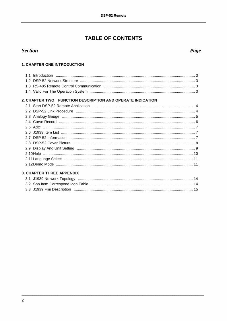
TABLE OF CONTENTS
Section Page
1. CHAPTER ONE INTRODUCTION 1.1 Introduction .................................................................................................................................... 3 1.2 DSP-52 Network Structure ............................................................................................................. 3 1.3 RS-485 Remote Control Communication ...................................................................................... 3 1.4 Valid For The Operation System .................................................................................................... 3
2. CHAPTER TWO FUNCTION DESCRIPTION AND OPERATE INDICATION 2.1 Start DSP-52 Remote Application .................................................................................................. 4 2.2 DSP-52 Link Procedure ................................................................................................................. 4 2.3 Analogy Gauge .............................................................................................................................. 5 2.4 Curve Record ................................................................................................................................. 6 2.5 Adtc ................................................................................................................................................ 7 2.6 J1939 Item List ............................................................................................................................... 7 2.7 DSP-52 Information ....................................................................................................................... 7 2.8 DSP-52 Cover Picture .................................................................................................................... 8 2.9 Display And Unit Setting ................................................................................................................ 9 2.10 Help .............................................................................................................................................. 10 2.11 Language Select .......................................................................................................................... 11 2.12 Demo Mode .................................................................................................................................. 11
3. CHAPTER THREE APPENDIX 3.1 J1939 Network Topology ............................................................................................................. 14 3.2 Spn Item Correspond Icon Table ................................................................................................. 14 3.3 J1939 Fmi Description ................................................................................................................. 15
DSP-52 Remote
______________________________________________________________________________________
3
1. INTRODUCTION
1.1 Introduction
The main function of the DSP-52 CAN Bus Reader is to extract data and fault diagnostic messages through the SAE-J1939 protocol. The DSP-52 Remote is a software program that can be installed on any PC and via connection from RS-485, to the DSP-52 CAN Bus Reader, user can command, access and extract all valuable information remotely from the connected PC. The obtained parameters are immediately shown in the active gauge illustrations and the system can record up to 100 sets of failure diagnostic codes and providing 24hrs historical data curve diagrams for 8 sets of preselected parameters.
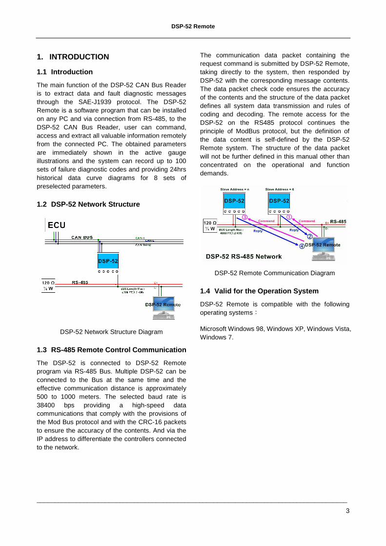
1.2 DSP-52 Network Structure
DSP-52 Network Structure Diagram
1.3 RS-485 Remote Control Communication
The DSP-52 is connected to DSP-52 Remote program via RS-485 Bus. Multiple DSP-52 can be connected to the Bus at the same time and the effective communication distance is approximately 500 to 1000 meters. The selected baud rate is 38400 bps providing a high-speed data communications that comply with the provisions of the Mod Bus protocol and with the CRC-16 packets to ensure the accuracy of the contents. And via the IP address to differentiate the controllers connected to the network.
The communication data packet containing the request command is submitted by DSP-52 Remote, taking directly to the system, then responded by DSP-52 with the corresponding message contents. The data packet check code ensures the accuracy of the contents and the structure of the data packet defines all system data transmission and rules of coding and decoding. The remote access for the DSP-52 on the RS485 protocol continues the principle of ModBus protocol, but the definition of the data content is self-defined by the DSP-52 Remote system. The structure of the data packet will not be further defined in this manual other than concentrated on the operational and function demands.
DSP-52 Remote Communication Diagram
1.4 Valid for the Operation System
DSP-52 Remote is compatible with the following operating systems:
Microsoft Windows 98, Windows XP, Windows Vista, Windows 7.
DSP-52 Remote
______________________________________________________________________________________
4
2. FUNCTION DESCRIPTION AND OPERATE INDICATION
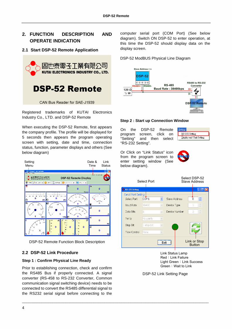
2.1 Start DSP-52 Remote Application
Registered trademarks of KUTAI Electronics Industry Co., LTD. and DSP-52 Remote
When executing the DSP-52 Remote, first appears the company profile. The profile will be displayed for 5 seconds then appears the program operating screen with setting, date and time, connection status, function, parameter displays and others (See below diagram)
Link
Status
Date &
Time
Setting
Menu
DSP-52 Remote Function Block Description
2.2 DSP-52 Link Procedure
Step 1 : Confirm Physical Line Ready
Prior to establishing connection, check and confirm the RS485 Bus if properly connected. A signal converter (RS-458 to RS-232 Converter, Common communication signal switching device) needs to be connected to convert the RS485 differential signal to the RS232 serial signal before connecting to the
computer serial port (COM Port) (See below diagram). Switch ON DSP-52 to enter operation, at this time the DSP-52 should display data on the display screen.
DSP-52 ModBUS Physical Line Diagram
Step 2 : Start up Connection Window
On the DSP-52 Remote program screen, click on “Setting” and then select “RS-232 Setting”.
Or Click on “Link Status” icon from the program screen to enter setting window (See below diagram).
Select DSP-52 Slave AddressSelect Port
Link or Stop Button
Link Status Lamp
Red:Link Failure
Light Green:Link Success
Green:Wait to Link
DSP-52 Link Setting Page
DSP-52 Remote
______________________________________________________________________________________
5
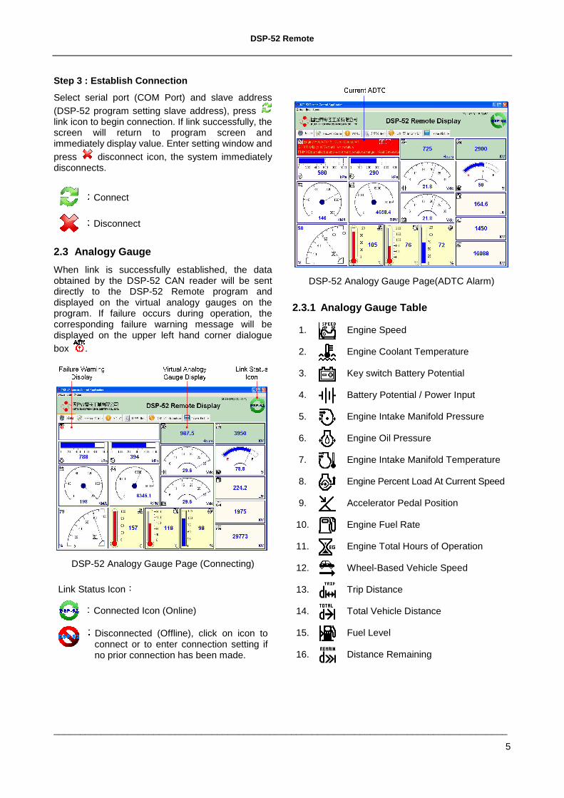
Step 3 : Establish Connection
Select serial port (COM Port) and slave address (DSP-52 program setting slave address), press link icon to begin connection. If link successfully, the screen will return to program screen and immediately display value. Enter setting window and press disconnect icon, the system immediately disconnects.
:
Connect
:
Disconnect
2.3 Analogy Gauge
When link is successfully established, the data obtained by the DSP-52 CAN reader will be sent directly to the DSP-52 Remote program and displayed on the virtual analogy gauges on the program. If failure occurs during operation, the corresponding failure warning message will be displayed on the upper left hand corner dialogue box .
DSP-52 Analogy Gauge Page (Connecting)
Link Status Icon:
:
Connected Icon (Online)
:Disconnected (Offline), click on icon to connect or to enter connection setting if no prior connection has been made.
DSP-52 Analogy Gauge Page(ADTC Alarm)
2.3.1 Analogy Gauge Table
1. Engine Speed
2. Engine Coolant Temperature
3. Key switch Battery Potential
4. Battery Potential / Power Input
5. Engine Intake Manifold Pressure
6. Engine Oil Pressure
7. Engine Intake Manifold Temperature
8. Engine Percent Load At Current Speed
9. Accelerator Pedal Position
10. Engine Fuel Rate
11. Engine Total Hours of Operation
12. Wheel-Based Vehicle Speed
13. Trip Distance
14. Total Vehicle Distance
15. Fuel Level
16. Distance Remaining
DSP-52 Remote
______________________________________________________________________________________
6
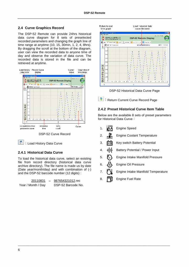
2.4 Curve Graphics Record
The DSP-52 Remote can provide 24hrs historical data curve diagram for 8 sets of preselected recorded parameters and changing the graph line of time range at anytime (10, 15, 30min, 1, 2, 4, 8hrs). By dragging the scroll at the bottom of the diagram, user can view the recorded data to anyone time of day and observe the variation of data curve. The recorded data is stored in the file and can be retrieved at anytime.
DSP-52 Curve Record :Load History Data Curve
2.4.1 Historical Data Curve
To load the historical data curve, select an existing file from record directory (historical data curve archive directory). The file name is made us by date (Date year/month/day) and with combination of (-) and the DSP-52 barcode number (12 digits) :
20110831 987654321012.rec Year / Month / Day DSP-52 Barcode No.
DSP-52 Historical Data Curve Page :Return Current Curve Record Page
2.4.2 Preset Historical Curve Item Table
Below are the available 8 sets of preset parameters for Historical Data Curve:
1. Engine Speed
2. Engine Coolant Temperature
3. Key switch Battery Potential
4. Battery Potential / Power Input
5. Engine Intake Manifold Pressure
6. Engine Oil Pressure
7. Engine Intake Manifold Temperature
8. Engine Fuel Rate
DSP-52 Remote
______________________________________________________________________________________
7
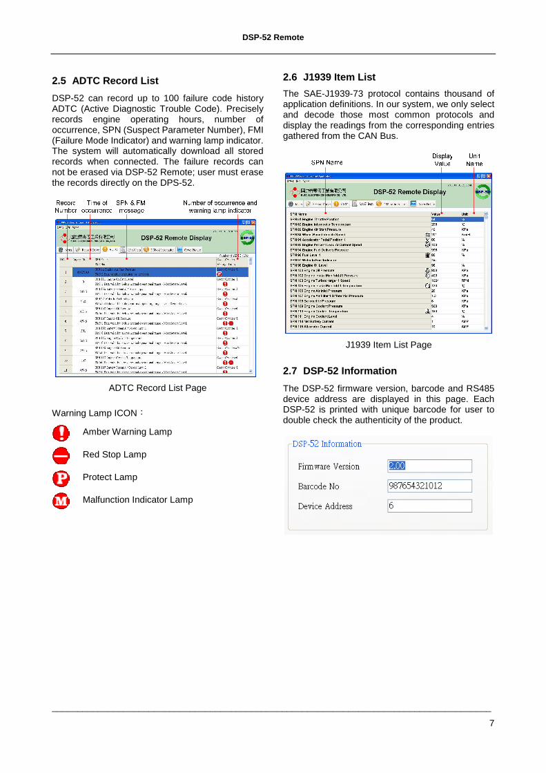
2.5 ADTC Record List
DSP-52 can record up to 100 failure code history ADTC (Active Diagnostic Trouble Code). Precisely records engine operating hours, number of occurrence, SPN (Suspect Parameter Number), FMI (Failure Mode Indicator) and warning lamp indicator. The system will automatically download all stored records when connected. The failure records can not be erased via DSP-52 Remote; user must erase the records directly on the DPS-52.
ADTC Record List Page
Warning Lamp ICON:
Amber Warning Lamp
Red Stop Lamp
Protect Lamp
Malfunction Indicator Lamp
2.6 J1939 Item List
The SAE-J1939-73 protocol contains thousand of application definitions. In our system, we only select and decode those most common protocols and display the readings from the corresponding entries gathered from the CAN Bus.
J1939 Item List Page
2.7 DSP-52 Information
The DSP-52 firmware version, barcode and RS485 device address are displayed in this page. Each DSP-52 is printed with unique barcode for user to double check the authenticity of the product.
DSP-52 Remote
______________________________________________________________________________________
8
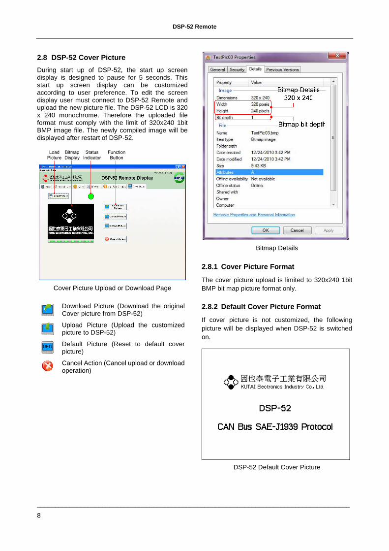
2.8 DSP-52 Cover Picture
During start up of DSP-52, the start up screen display is designed to pause for 5 seconds. This start up screen display can be customized according to user preference. To edit the screen display user must connect to DSP-52 Remote and upload the new picture file. The DSP-52 LCD is 320 x 240 monochrome. Therefore the uploaded file format must comply with the limit of 320x240 1bit BMP image file. The newly compiled image will be displayed after restart of DSP-52.
Load
Picture
Bitmap
Display
Status
Indicator
Function
Button
Cover Picture Upload or Download Page
Download Picture (Download the original Cover picture from DSP-52)
Upload Picture (Upload the customized picture to DSP-52)
Default Picture (Reset to default cover picture)
Cancel Action (Cancel upload or download operation)
Bitmap Details
2.8.1 Cover Picture Format
The cover picture upload is limited to 320x240 1bit BMP bit map picture format only.
2.8.2 Default Cover Picture Format
If cover picture is not customized, the following picture will be displayed when DSP-52 is switched on.
DSP-52 Default Cover Picture
DSP-52 Remote
______________________________________________________________________________________
9
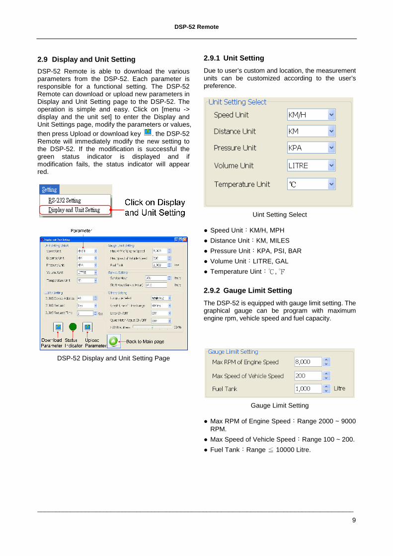
2.9 Display and Unit Setting
DSP-52 Remote is able to download the various parameters from the DSP-52. Each parameter is responsible for a functional setting. The DSP-52 Remote can download or upload new parameters in Display and Unit Setting page to the DSP-52. The operation is simple and easy. Click on [menu -> display and the unit set] to enter the Display and Unit Settings page, modify the parameters or values, then press Upload or download key . the DSP-52 Remote will immediately modify the new setting to the DSP-52. If the modification is successful the green status indicator is displayed and if modification fails, the status indicator will appear red.
DSP-52 Display and Unit Setting Page
2.9.1 Unit Setting
Due to user’s custom and location, the measurement units can be customized according to the user’s preference.
Uint Setting Select
Speed Unit:KM/H, MPH
Distance Unit:KM, MILES
Pressure Unit:KPA, PSI, BAR
Volume Unit:LITRE, GAL
Temperature Uint:,
2.9.2 Gauge Limit Setting
The DSP-52 is equipped with gauge limit setting. The graphical gauge can be program with maximum engine rpm, vehicle speed and fuel capacity.
Gauge Limit Setting
Max RPM of Engine Speed:Range 2000 ~ 9000 RPM.
Max Speed of Vehicle Speed:Range 100 ~ 200.
Fuel Tank:Range 10000 Litre≦ .
DSP-52 Remote
______________________________________________________________________________________
10
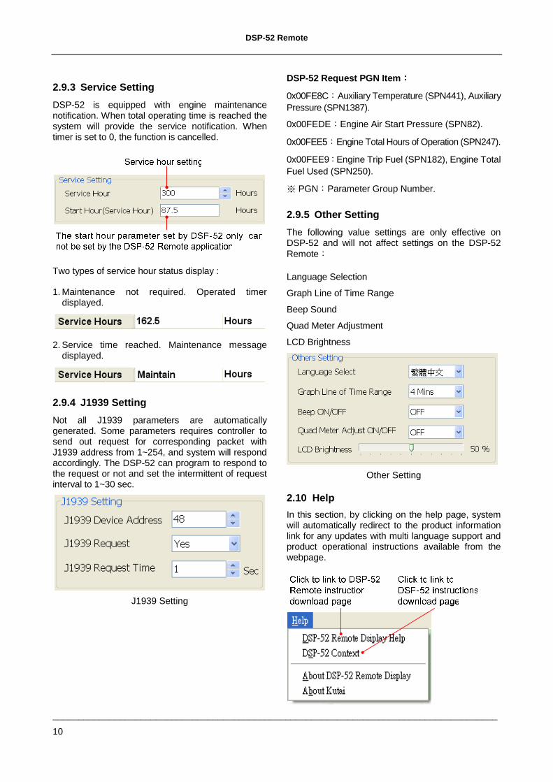
2.9.3 Service Setting
DSP-52 is equipped with engine maintenance notification. When total operating time is reached the system will provide the service notification. When timer is set to 0, the function is cancelled.
Two types of service hour status display :
1. Maintenance not required. Operated timer displayed.
2. Service time reached. Maintenance message displayed.
2.9.4 J1939 Setting
Not all J1939 parameters are automatically generated. Some parameters requires controller to send out request for corresponding packet with J1939 address from 1~254, and system will respond accordingly. The DSP-52 can program to respond to the request or not and set the intermittent of request interval to 1~30 sec.
J1939 Setting
DSP-52 Request PGN Item::::
0x00FE8C:Auxiliary Temperature (SPN441), Auxiliary Pressure (SPN1387).
0x00FEDE:Engine Air Start Pressure (SPN82).
0x00FEE5:Engine Total Hours of Operation (SPN247).
0x00FEE9:Engine Trip Fuel (SPN182), Engine Total Fuel Used (SPN250).
※ PGN:Parameter Group Number.
2.9.5 Other Setting
The following value settings are only effective on DSP-52 and will not affect settings on the DSP-52 Remote:
Language Selection
Graph Line of Time Range
Beep Sound
Quad Meter Adjustment
LCD Brightness
Other Setting
2.10 Help
In this section, by clicking on the help page, system will automatically redirect to the product information link for any updates with multi language support and product operational instructions available from the webpage.
DSP-52 Remote
______________________________________________________________________________________
11
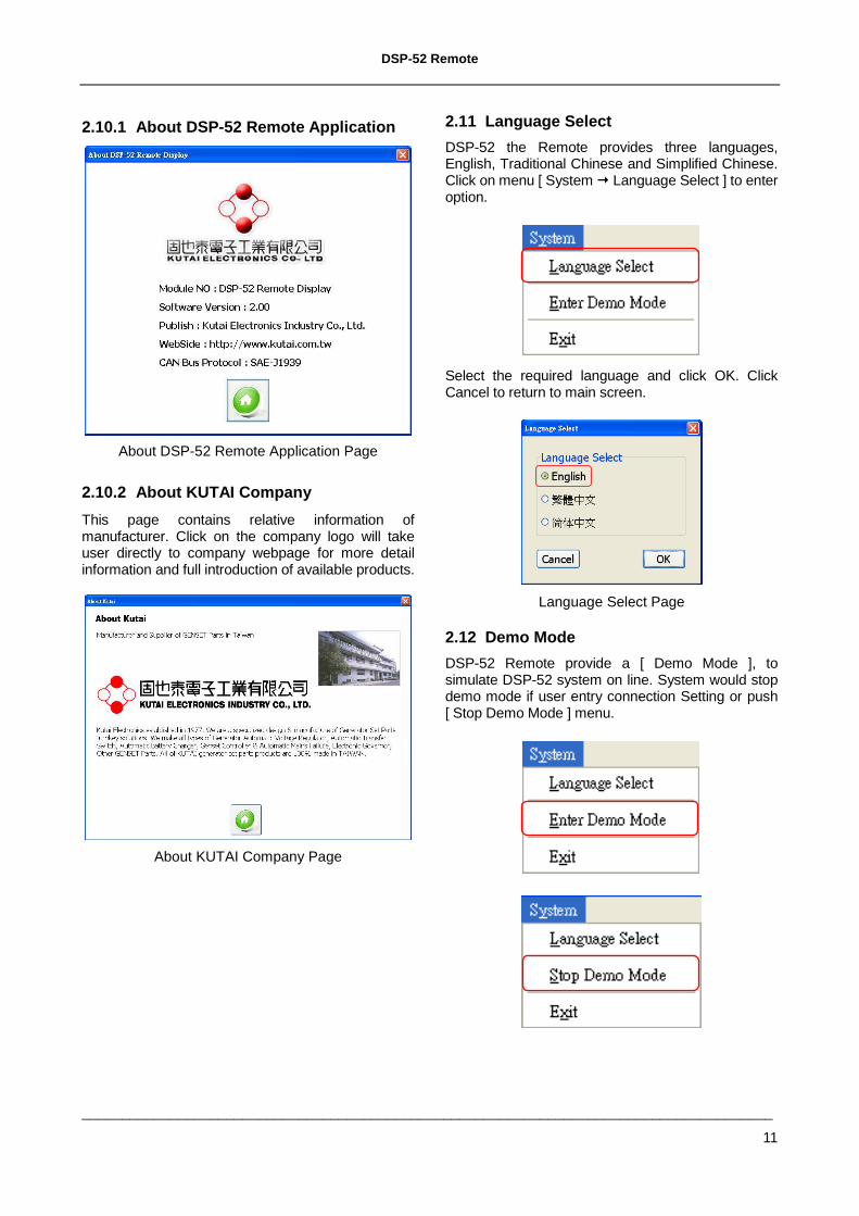
2.10.1 About DSP-52 Remote Application
About DSP-52 Remote Application Page
2.10.2 About KUTAI Company
This page contains relative information of manufacturer. Click on the company logo will take user directly to company webpage for more detail information and full introduction of available products.
About KUTAI Company Page
2.11 Language Select
DSP-52 the Remote provides three languages, English, Traditional Chinese and Simplified Chinese. Click on menu [ System Language Select ] to enter option.
Select the required language and click OK. Click Cancel to return to main screen.
Language Select Page
2.12 Demo Mode
DSP-52 Remote provide a [ Demo Mode ], to simulate DSP-52 system on line. System would stop demo mode if user entry connection Setting or push [ Stop Demo Mode ] menu.
DSP-52 Remote
______________________________________________________________________________________
12
3. CHAPTER FOUR APPENDIX
3.1 J1939 Network Topology
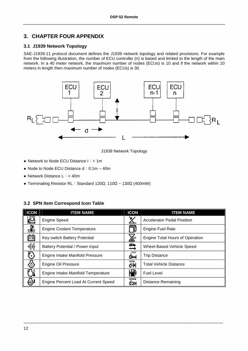
SAE-J1939-11 protocol document defines the J1939 network topology and related provisions. For example from the following illustration, the number of ECU controller (n) is based and limited to the length of the main network. In a 40 meter network, the maximum number of nodes (ECUs) is 10 and if the network within 10 meters in length then maximum number of nodes (ECUs) is 30.
J1939 Network Topology
Network to Node ECU Distance I:< 1m
Node to Node ECU Distance d:0.1m ~ 40m
Network Distance L:< 40m
Terminating Resistor RL:Standard 120Ω, 110Ω ~ 130Ω (400mW)
3.2 SPN Item Correspond Icon Table
ICON ITEM NAME ICON ITEM NAME
Engine Speed Accelerator Pedal Position
Engine Coolant Temperature Engine Fuel Rate
Key switch Battery Potential Engine Total Hours of Operation
Battery Potential / Power Input Wheel-Based Vehicle Speed
Engine Intake Manifold Pressure Trip Distance
Engine Oil Pressure Total Vehicle Distance
Engine Intake Manifold Temperature Fuel Level
Engine Percent Load At Current Speed Distance Remaining
DSP-52 Remote
______________________________________________________________________________________
13
3.3 J1939 FMI Descript
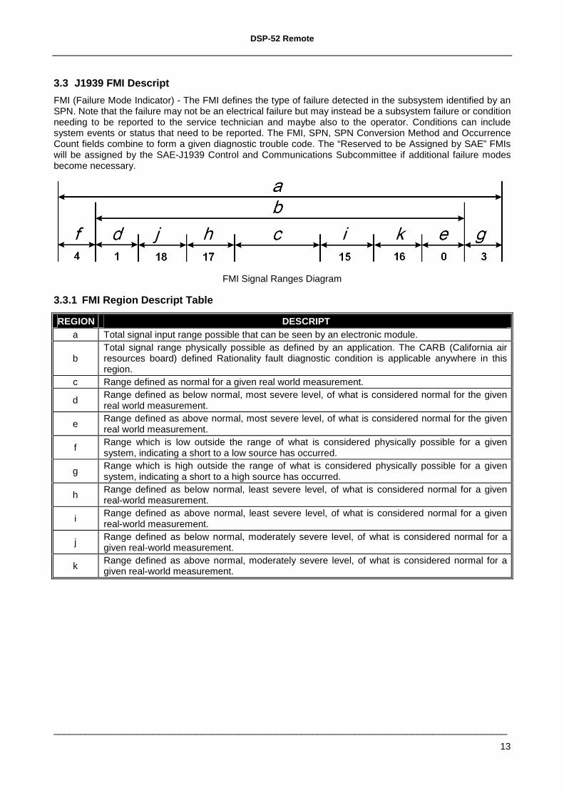
FMI (Failure Mode Indicator) - The FMI defines the type of failure detected in the subsystem identified by an SPN. Note that the failure may not be an electrical failure but may instead be a subsystem failure or condition needing to be reported to the service technician and maybe also to the operator. Conditions can include system events or status that need to be reported. The FMI, SPN, SPN Conversion Method and Occurrence Count fields combine to form a given diagnostic trouble code. The “Reserved to be Assigned by SAE” FMIs will be assigned by the SAE-J1939 Control and Communications Subcommittee if additional failure modes become necessary.
FMI Signal Ranges Diagram
3.3.1 FMI Region Descript Table
REGION DESCRIPT a Total signal input range possible that can be seen by an electronic module.
b Total signal range physically possible as defined by an application. The CARB (California air resources board) defined Rationality fault diagnostic condition is applicable anywhere in this region.
c Range defined as normal for a given real world measurement.
d Range defined as below normal, most severe level, of what is considered normal for the given real world measurement.
e Range defined as above normal, most severe level, of what is considered normal for the given real world measurement.
f Range which is low outside the range of what is considered physically possible for a given system, indicating a short to a low source has occurred.
g Range which is high outside the range of what is considered physically possible for a given system, indicating a short to a high source has occurred.
h Range defined as below normal, least severe level, of what is considered normal for a given real-world measurement.
i Range defined as above normal, least severe level, of what is considered normal for a given real-world measurement.
j Range defined as below normal, moderately severe level, of what is considered normal for a given real-world measurement.
k Range defined as above normal, moderately severe level, of what is considered normal for a given real-world measurement.
DSP-52 Remote
______________________________________________________________________________________
14
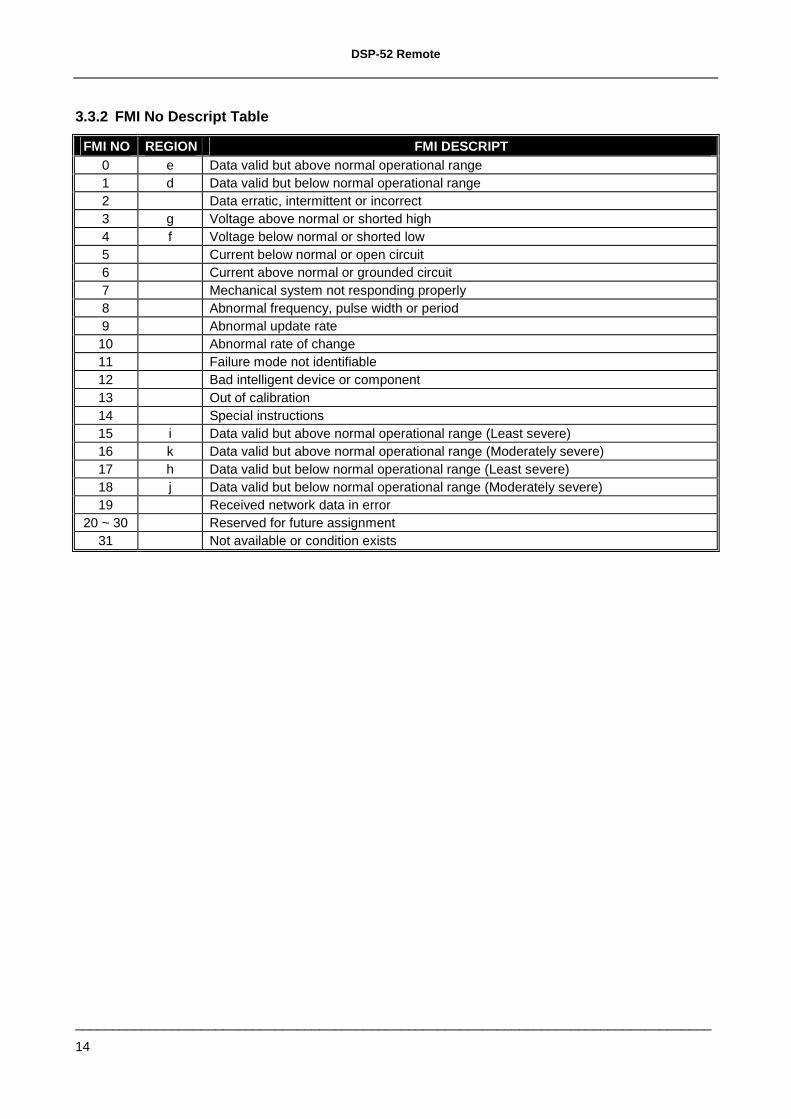
3.3.2 FMI No Descript Table
FMI NO REGION FMI DESCRIPT 0 e Data valid but above normal operational range 1 d Data valid but below normal operational range 2 Data erratic, intermittent or incorrect 3 g Voltage above normal or shorted high 4 f Voltage below normal or shorted low 5 Current below normal or open circuit 6 Current above normal or grounded circuit 7 Mechanical system not responding properly 8 Abnormal frequency, pulse width or period 9 Abnormal update rate 10 Abnormal rate of change 11 Failure mode not identifiable 12 Bad intelligent device or component 13 Out of calibration 14 Special instructions 15 i Data valid but above normal operational range (Least severe) 16 k Data valid but above normal operational range (Moderately severe) 17 h Data valid but below normal operational range (Least severe) 18 j Data valid but below normal operational range (Moderately severe) 19 Received network data in error
20 ~ 30 Reserved for future assignment 31 Not available or condition exists