DSD-080 - Datakom · display screen, the unit shows system ... Installation on vibrating places or...
15
DSD-080 User Manual V-1.0 1 DSD-080 SEISMIC SECURITY PANEL DATAKOM DSD-080 Seismic Security Panel monitors seismic motions of a strong earthquake and provides relay output signals from it. Output signals are used to shut-off critical installations as natural gas and LPG systems, generators, elevators and the like. The unit helps reducing damages of a probable earthquake. On its graphical display screen, the unit shows system status. DSD-080 incorporates highly sensitive triple axis seismic sensors. The unit is maintenance free and capable of making self-test. The earthquake sensing specifications of DSD-080 conforms to both ANSI Z21.80 (1981), ASCE 25-97 and TS-12884(2002) standards. DSD-080 operates on mains with a battery backup. 24V/1.2A-h batteries are incorporated to the unit. The unit provides automatic battery charging feature. During long mains failures, if batteries get low, the unit gives audible and visible alarm. The unit provides 5 high power relay outputs. Through the programming menu, outputs may be assigned to any function selected from a list. • Wide operating voltage range • Conformal to earhquake standards • Triple axis motion detection • Automatic self-test • Internal audible warning • Internal 24V battery • 5 programmable relay outputs (5Amp) • Visual indicators for battery status • Wide operating temperature range Sensor Specifications Sensor type: Triple axis polysilicon semiconductor acceleration sensors. Sensor operating limits: ±2g. Sensor failure limit: more than 50g. Acceleration threshold: TS12884, ANSI Z21.80 (1981), ASCE 25-97 Detection delay: 0.5sn. maximum Frequency range: 0.5Hz to 25Hz FEATURES DESCRIPTION
Transcript of DSD-080 - Datakom · display screen, the unit shows system ... Installation on vibrating places or...

DSD-080 User Manual V-1.0
1
DSD-080
SEISMIC
SECURITY
PANEL
DATAKOM DSD-080 Seismic Security Panel monitors seismic motions of a strong earthquake and provides relay output signals from it. Output signals are used to shut-off critical installations as natural gas and LPG systems, generators, elevators and the like.
The unit helps reducing damages of a probable earthquake. On its graphical display screen, the unit shows system status.
DSD-080 incorporates highly sensitive triple axis seismic sensors. The unit is maintenance free and capable of making self-test.
The earthquake sensing specifications of DSD-080 conforms to both ANSI Z21.80 (1981), ASCE 25-97 and TS-12884(2002) standards.
DSD-080 operates on mains with a battery backup. 24V/1.2A-h batteries are incorporated to the unit. The unit provides automatic battery charging feature. During long mains failures, if batteries get low, the unit gives audible and visible alarm.
The unit provides 5 high power relay outputs. Through the programming menu, outputs may be assigned to any function selected from a list.
• Wide operating voltage range
• Conformal to earhquake standards
• Triple axis motion detection
• Automatic self-test
• Internal audible warning
• Internal 24V battery
• 5 programmable relay outputs (5Amp)
• Visual indicators for battery status
• Wide operating temperature range
Sensor Specifications
Sensor type: Triple axis polysilicon semiconductor acceleration sensors.
Sensor operating limits: ±2g.
Sensor failure limit: more than 50g.
Acceleration threshold: TS12884, ANSI Z21.80 (1981), ASCE 25-97
Detection delay: 0.5sn. maximum
Frequency range: 0.5Hz to 25Hz
FEATURES DESCRIPTION
DSD-080 User Manual V-1.0
2
Any unauthorized use or copying of the contents or any part of this document is prohibited.
This document describes minimum requirements and necessary steps for the successful installation of the DSD-080 family units.
Follow carefully advices given in the document. These are often good practices for the installation which reduce future issues.
For all technical queries please contact Datakom at below e-mail address:
REVISION DATE WRITTEN DESCRIPTION
01 20.12.2016 MH First edition
CAUTION: Potential risk of injury or death.
WARNING: Potential risk of malfunction or material damage.
ATTENTION: Useful hints for the understanding of device operation.
TERMINOLOGY
REVISION HISTORY
ABOUT THIS DOCUMENT
COPYRIGHT NOTICE

DSD-080 User Manual V-1.0
3
Electrical equipment should be installed only by qualified specialist. No responsibility is assured by the manufacturer or any of its subsidiaries for any consequences resulting from the non-compliance to these instructions.
Check the unit for cracks and damages due to transportation. Do not install damaged equipment.
Do not open the unit. There is no serviceable parts inside.
Fuses must be connected to phase voltage inputs, in close proximity of the unit.
Fuses must be of fast type (FF) with a maximum rating of 6A.
Disconnect all power before working on equipment.
When the unit is connected to the network do not touch terminals.
Any electrical parameter applied to the device must be in the range specified in the user manual.
Do not try to clean the device with solvent or the like. Only clean with a dry cloth.
Verify correct terminal connections before applying power.
Designed for vertical wall mounting.
SAFETY NOTICE
Failure to follow below instructions will result in death or serious injury
DSD-080 User Manual V-1.0
4
Section 1. COMMISSIONING 2. INSTALLATION
2.1. DIMENSIONS 2.2. MECHANICAL INSTALLATION 2.3. ELECTRICAL INSTALLATION 2.4. INSTALLATION DIAGRAM
3. PUSHBUTTON FUNCTIONS 4. DISPLAYS 5. ALARMS 6. DEVICE CONFIGURATION
6.1. ENTERING THE PROGRAM MODE 6.2. CHANGING PARAMETER VALUE 6.3. LIST OF PARAMETERS 6.4. LIST OF FUNCTIONS 6.5. RELAY FUNCTIONS
7. TEST MENU SCREEN 8. TECHNICAL SPECIFICATIONS
TABLE OF CONTENTS

DSD-080 User Manual V-1.0
5
Before installation:
Read the user manual carefully, determine the correct connection diagram.
Install the unit to a flat surface. A vertical surface should be preferred.
Fix the unit to the wall through screw openings.
Make electrical connections with plugs removed from sockets, then place plugs to their sockets. Otherwise you may destroy the socket and connector.
Be sure that the ambient temperature will not exceed the maximum operating temperature limit.
Below conditions may damage the device:
Incorrect connections.
Incorrect power supply voltage.
Overload or short circuit at relay outputs
Below conditions may cause abnormal operation:
Power supply voltage below minimum acceptable level.
Power supply frequency out of specified limits
Installation on vibrating places or vibrating parts.
1. COMMISSIONING
DSD-080 User Manual V-1.0
6
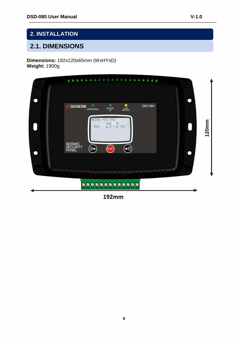
Dimensions: 192x120x65mm (WxHYxD) Weight: 1900g
2. INSTALLATION
2.1. DIMENSIONS
192mm

DSD-080 User Manual V-1.0
7
The unit is designed for wall mounting. Please mount on a flat surface through screw openings.
2.2 MECHANICAL INSTALLATION
WALL
DSD-080 User Manual V-1.0
8
Although the unit is protected against electromagnetic disturbance, excessive disturbance can affect the operation, measurement precision and data communication quality.
ALWAYS remove plug connectors when inserting wires with a screwdriver.
Fuse must be connected to phase voltage input, in close proximity of the unit.
Fuses must be of fast type (FF) with a maximum rating of 6A.
Use cables of appropriate temperature range.
Use adequate cable section, at least 0.75mm2 (AWG18).
Be sure that relay outputs are not overloaded. Use additional contactors when necessary.
Do not install the unit close to high electromagnetic noise emitting devices like contactors, high current busbars, switchmode power supplies and the like.
2.3 ELECTRICAL INSTALLATION

DSD-080 User Manual V-1.0
9
2.4 CONNECTION DIAGRAM

DSD-080 User Manual V-1.0
10
Three buttons on the front panel provide access to configuration and test screens.
BUTTON FUNCTION
Used to record modifications at the programming mode.
HELD PRESSED FOR 5 SECONDS:
Alarms and alarm relay are reset.
Used to navigate between menus.
Programming mode: Increase related value.
Used to navigate between menus.
Programming mode: Decrease related value.
HELD PRESSED TOGETHER FOR 3 SECONDS:
Enters the programming mode. If already in programming mode, then exits programming mode.
HELD PRESSED TOGETHER FOR 3 SECONDS:
If both pushbuttons are held pressed during 3 seconds, then enters Test mode.
3. PUSHBUTTON FUNCTIONS
DSD-080 User Manual V-1.0
11
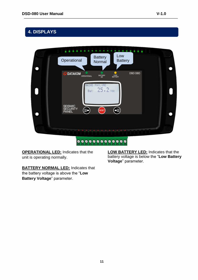
OPERATIONAL LED: Indicates that the
unit is operating normally.
BATTERY NORMAL LED: Indicates that
the battery voltage is above the “Low
Battery Voltage” parameter.
LOW BATTERY LED: Indicates that the battery voltage is below the “Low Battery Voltage” parameter.
4. DISPLAYS
Operational Battery Normal
Low Battery

DSD-080 User Manual V-1.0
12
The unit provides two different alarm levels for “Weak Motion” and “Strong Motion”.
The unit has a closed circuit detector at the solenoid relay output. If the solenoid connection is broken, then a “no solenoid” alarm will occur.
Additionally a “Low Battery” alarm is provided.
Any of the above alarms may be assigned to any relay output. However the Solenoid output can be only assigned as “Strong Motion” alarm.
When any alarm occurs, related relay outputs become active and the unit gives an audible alarm.
By depresing the RESET pushbutton, alarms are reset and relays return to their initial position.
ALARM MESSAGE
DESCRIPTION
LOW BATTERY
Occurs when the battery voltage is below the “Low Battery Voltage” parameter.
WEAK MOTION
Occurs when the measured acceleration is over the user-defined threshold for the weak motion.
STRONG MOTION
Occurs when the measured acceleration is over the threshold for the strong motion. This threshold is defined by international standards and is not adjustable.
NO SOLENOID
Occurs when there is no connection at solenoid output, or when the conductor wires are broken.
5. ALARMS
DSD-080 User Manual V-1.0
13
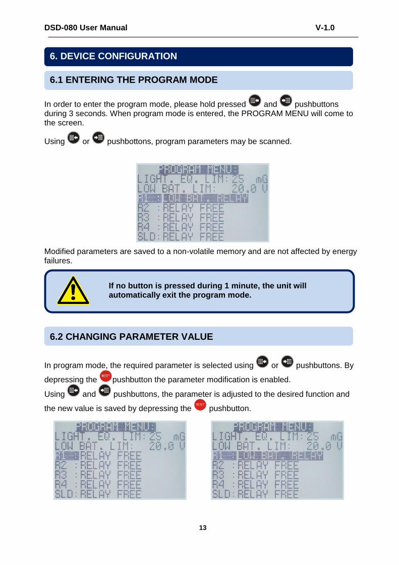
In order to enter the program mode, please hold pressed and pushbuttons during 3 seconds. When program mode is entered, the PROGRAM MENU will come to the screen.
Using or pushbottons, program parameters may be scanned.
Modified parameters are saved to a non-volatile memory and are not affected by energy failures.
In program mode, the required parameter is selected using or pushbuttons. By
depressing the pushbutton the parameter modification is enabled.
Using and pushbuttons, the parameter is adjusted to the desired function and
the new value is saved by depressing the pushbutton.
If no button is pressed during 1 minute, the unit will automatically exit the program mode.
6.2 CHANGING PARAMETER VALUE
6.1 ENTERING THE PROGRAM MODE
6. DEVICE CONFIGURATION
DSD-080 User Manual V-1.0
14
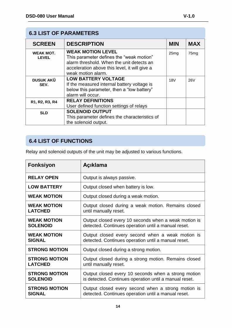
SCREEN DESCRIPTION MIN MAX
WEAK MOT. LEVEL
WEAK MOTION LEVEL This parameter defines the “weak motion” alarm threshold. When the unit detects an acceleration above this level, it will give a weak motion alarm.
25mg 75mg
DUSUK AKÜ SEV.
LOW BATTERY VOLTAGE If the measured internal battery voltage is below this parameter, then a “low battery” alarm will occur.
18V 26V
R1, R2, R3, R4 RELAY DEFINITIONS User defined function settings of relays
SLD SOLENOID OUTPUT This parameter defines the characteristics of the solenoid output.
Relay and solenoid outputs of the unit may be adjusted to various functions.
Fonksiyon Açıklama
RELAY OPEN Output is always passive.
LOW BATTERY Output closed when battery is low.
WEAK MOTION Output closed during a weak motion.
WEAK MOTION LATCHED
Output closed during a weak motion. Remains closed until manually reset.
WEAK MOTION SOLENOID
Output closed every 10 seconds when a weak motion is detected. Continues operation until a manual reset.
WEAK MOTION SIGNAL
Output closed every second when a weak motion is detected. Continues operation until a manual reset.
STRONG MOTION Output closed during a strong motion.
STRONG MOTION LATCHED
Output closed during a strong motion. Remains closed until manually reset.
STRONG MOTION SOLENOID
Output closed every 10 seconds when a strong motion is detected. Continues operation until a manual reset.
STRONG MOTION SIGNAL
Output closed every second when a strong motion is detected. Continues operation until a manual reset.
6.3 LIST OF PARAMETERS
6.4 LIST OF FUNCTIONS
DSD-080 User Manual V-1.0
15
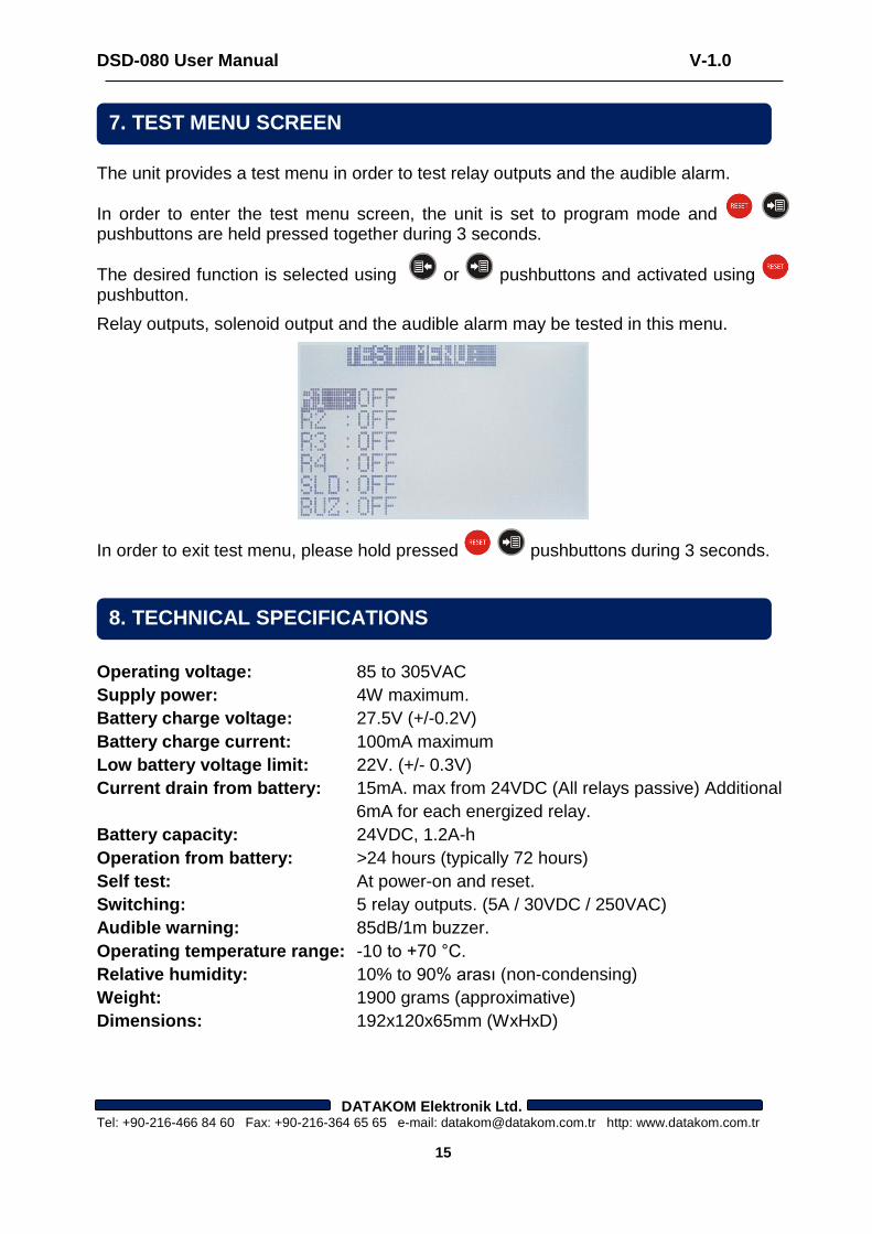
The unit provides a test menu in order to test relay outputs and the audible alarm.
In order to enter the test menu screen, the unit is set to program mode and pushbuttons are held pressed together during 3 seconds.
The desired function is selected using or pushbuttons and activated using pushbutton.
Relay outputs, solenoid output and the audible alarm may be tested in this menu.
In order to exit test menu, please hold pressed pushbuttons during 3 seconds.
Operating voltage: 85 to 305VAC
Supply power: 4W maximum.
Battery charge voltage: 27.5V (+/-0.2V)
Battery charge current: 100mA maximum
Low battery voltage limit: 22V. (+/- 0.3V)
Current drain from battery: 15mA. max from 24VDC (All relays passive) Additional
6mA for each energized relay.
Battery capacity: 24VDC, 1.2A-h
Operation from battery: >24 hours (typically 72 hours)
Self test: At power-on and reset.
Switching: 5 relay outputs. (5A / 30VDC / 250VAC)
Audible warning: 85dB/1m buzzer.
Operating temperature range: -10 to +70 °C.
Relative humidity: 10% to 90% arası (non-condensing)
Weight: 1900 grams (approximative)
Dimensions: 192x120x65mm (WxHxD)
DATAKOM Elektronik Ltd. Tel: +90-216-466 84 60 Fax: +90-216-364 65 65 e-mail: [email protected] http: www.datakom.com.tr
7. TEST MENU SCREEN
8. TECHNICAL SPECIFICATIONS