DSC pc5008 v2-12c intl (300-50) 29003982 r003
52
Installation Manual WARNING This manual contains information on limitations regarding product use and function and information on the limitations as to liability of the manufacturer. The entire manual should be carefully read. PC5008 v2.1C DLS-1 v6.3S and higher
-
Upload
sertek-servicios-tecnologicos -
Category
Documents
-
view
221 -
download
0
description
pc5008 v2-12c intl (300-50) 29003982 r003
Transcript of DSC pc5008 v2-12c intl (300-50) 29003982 r003

Installation Manual
WARNINGThis manual contains information on limitations regarding product use and function and information on the
limitations as to liability of the manufacturer. The entire manual should be carefully read.
PC5008 v2.1CDLS-1 v6.3S and higher

WARNING Please Read CarefullyNote to InstallersThis warning contains vital information. As the only individual in contact with system users, it is yourresponsibility to bring each item in this warning to the attention of the users of this system.System FailuresThis system has been carefully designed to be as effective as possible. There are circumstances, however,involving fire, burglary, or other types of emergencies where it may not provide protection. Any alarm sys-tem of any type may be compromised deliberately or may fail to operate as expected for a variety of reasons.Some but not all of these reasons may be: Inadequate InstallationA security system must be installed properly in order to provide adequate protection. Every installationshould be evaluated by a security professional to ensure that all access points and areas are covered. Locksand latches on windows and doors must be secure and operate as intended. Windows, doors, walls, ceilingsand other building materials must be of sufficient strength and construction to provide the level of protectionexpected. A reevaluation must be done during and after any construction activity. An evaluation by the fireand/or police department is highly recommended if this service is available. Criminal KnowledgeThis system contains security features which were known to be effective at the time of manufacture. It ispossible for persons with criminal intent to develop techniques which reduce the effectiveness of these fea-tures. It is important that a security system be reviewed periodically to ensure that its features remain effec-tive and that it be updated or replaced if it is found that it does not provide the protection expected. Access by IntrudersIntruders may enter through an unprotected access point, circumvent a sensing device, evade detection bymoving through an area of insufficient coverage, disconnect a warning device, or interfere with or preventthe proper operation of the system. Power FailureControl units, intrusion detectors, smoke detectors and many other security devices require an adequatepower supply for proper operation. If a device operates from batteries, it is possible for the batteries to fail.Even if the batteries have not failed, they must be charged, in good condition and installed correctly. If adevice operates only by AC power, any interruption, however brief, will render that device inoperative whileit does not have power. Power interruptions of any length are often accompanied by voltage fluctuationswhich may damage electronic equipment such as a security system. After a power interruption has occurred,immediately conduct a complete system test to ensure that the system operates as intended. Failure of Replaceable BatteriesThis system’s wireless transmitters have been designed to provide several years of battery life under normalconditions. The expected battery life is a function of the device environment, usage and type. Ambient con-ditions such as high humidity, high or low temperatures, or large temperature fluctuations may reduce theexpected battery life. While each transmitting device has a low battery monitor which identifies when thebatteries need to be replaced, this monitor may fail to operate as expected. Regular testing and maintenancewill keep the system in good operating condition. Compromise of Radio Frequency (Wireless) DevicesSignals may not reach the receiver under all circumstances which could include metal objects placed on ornear the radio path or deliberate jamming or other inadvertent radio signal interference. System UsersA user may not be able to operate a panic or emergency switch possibly due to permanent or temporaryphysical disability, inability to reach the device in time, or unfamiliarity with the correct operation. It isimportant that all system users be trained in the correct operation of the alarm system and that they knowhow to respond when the system indicates an alarm. Smoke DetectorsSmoke detectors that are a part of this system may not properly alert occupants of a fire for a number of rea-sons, some of which follow. The smoke detectors may have been improperly installed or positioned. Smokemay not be able to reach the smoke detectors, such as when the fire is in a chimney, walls or roofs, or on theother side of closed doors. Smoke detectors may not detect smoke from fires on another level of the resi-dence or building.Every fire is different in the amount of smoke produced and the rate of burning. Smoke detectors cannotsense all types of fires equally well. Smoke detectors may not provide timely warning of fires caused bycarelessness or safety hazards such as smoking in bed, violent explosions, escaping gas, improper storage offlammable materials, overloaded electrical circuits, children playing with matches or arson.Even if the smoke detector operates as intended, there may be circumstances when there is insufficient warn-ing to allow all occupants to escape in time to avoid injury or death. Motion DetectorsMotion detectors can only detect motion within the designated areas as shown in their respective installationinstructions. They cannot discriminate between intruders and intended occupants. Motion detectors do notprovide volumetric area protection. They have multiple beams of detection and motion can only be detectedin unobstructed areas covered by these beams. They cannot detect motion which occurs behind walls, ceil-ings, floor, closed doors, glass partitions, glass doors or windows. Any type of tampering whether intentionalor unintentional such as masking, painting, or spraying of any material on the lenses, mirrors, windows orany other part of the detection system will impair its proper operation.Passive infrared motion detectors operate by sensing changes in temperature. However their effectivenesscan be reduced when the ambient temperature rises near or above body temperature or if there are intentionalor unintentional sources of heat in or near the detection area. Some of these heat sources could be heaters,radiators, stoves, barbeques, fireplaces, sunlight, steam vents, lighting and so on. Warning Devices Warning devices such as sirens, bells, horns, or strobes may not warn people or waken someone sleeping ifthere is an intervening wall or door. If warning devices are located on a different level of the residence orpremise, then it is less likely that the occupants will be alerted or awakened. Audible warning devices maybe interfered with by other noise sources such as stereos, radios, televisions, air conditioners or other appli-ances, or passing traffic. Audible warning devices, however loud, may not be heard by a hearing-impairedperson. Telephone LinesIf telephone lines are used to transmit alarms, they may be out of service or busy for certain periods of time.Also an intruder may cut the telephone line or defeat its operation by more sophisticated means which maybe difficult to detect. Insufficient TimeThere may be circumstances when the system will operate as intended, yet the occupants will not be pro-tected from the emergency due to their inability to respond to the warnings in a timely manner. If the systemis monitored, the response may not occur in time to protect the occupants or their belongings. Component FailureAlthough every effort has been made to make this system as reliable as possible, the system may fail to func-tion as intended due to the failure of a component. Inadequate TestingMost problems that would prevent an alarm system from operating as intended can be found by regular test-ing and maintenance. The complete system should be tested weekly and immediately after a break-in, anattempted break-in, a fire, a storm, an earthquake, an accident, or any kind of construction activity inside oroutside the premises. The testing should include all sensing devices, keypads, consoles, alarm indicatingdevices and any other operational devices that are part of the system. Security and InsuranceRegardless of its capabilities, an alarm system is not a substitute for property or life insurance. An alarm sys-tem also is not a substitute for property owners, renters, or other occupants to act prudently to prevent orminimize the harmful effects of an emergency situation.
Limited WarrantyDigital Security Controls Ltd. warrants the original purchaser that for a period of twelve months from thedate of purchase, the product shall be free of defects in materials and workmanship under normal use. Dur-ing the warranty period, Digital Security Controls Ltd. shall, at its option, repair or replace any defectiveproduct upon return of the product to its factory, at no charge for labour and materials. Any replacement and/or repaired parts are warranted for the remainder of the original warranty or ninety (90) days, whichever islonger. The original owner must promptly notify Digital Security Controls Ltd. in writing that there is defectin material or workmanship, such written notice to be received in all events prior to expiration of the war-ranty period.
International WarrantyThe warranty for international customers is the same as for any customer within Canada and the UnitedStates, with the exception that Digital Security Controls Ltd. shall not be responsible for any customs fees,taxes, or VAT that may be due.
Warranty ProcedureTo obtain service under this warranty, please return the item(s) in question to the point of purchase. Allauthorized distributors and dealers have a warranty program. Anyone returning goods to Digital SecurityControls Ltd. must first obtain an authorization number. Digital Security Controls Ltd. will not accept anyshipment whatsoever for which prior authorization has not been obtained.
Conditions to Void WarrantyThis warranty applies only to defects in parts and workmanship relating to normal use. It does not cover:
• damage incurred in shipping or handling;
• damage caused by disaster such as fire, flood, wind, earthquake or lightning;
• damage due to causes beyond the control of Digital Security Controls Ltd. such as excessive voltage,mechanical shock or water damage;
• damage caused by unauthorized attachment, alterations, modifications or foreign objects;
• damage caused by peripherals (unless such peripherals were supplied by Digital Security Controls Ltd.);
• defects caused by failure to provide a suitable installation environment for the products;
• damage caused by use of the products for purposes other than those for which it was designed;
• damage from improper maintenance;
• damage arising out of any other abuse, mishandling or improper application of the products.
Digital Security Controls Ltd.’s liability for failure to repair the product under this warranty after a reason-able number of attempts will be limited to a replacement of the product, as the exclusive remedy for breachof warranty. Under no circumstances shall Digital Security Controls Ltd. be liable for any special, incidental,or consequential damages based upon breach of warranty, breach of contract, negligence, strict liability, orany other legal theory. Such damages include, but are not limited to, loss of profits, loss of the product or anyassociated equipment, cost of capital, cost of substitute or replacement equipment, facilities or services,down time, purchaser’s time, the claims of third parties, including customers, and injury to property.
Disclaimer of Warranties
Digital Security Controls Ltd. recommends that the entire system be completely tested on aregular basis. However, despite frequent testing, and due to, but not limited to, criminal tampering or electri-cal disruption, it is possible for this product to fail to perform as expected.
Installer’s LockoutAny products returned to DSC which have the Installer’s Lockout option enabled and exhibit no other prob-lems will be subject to a service charge.
Out of Warranty RepairsDigital Security Controls Ltd. will at its option repair or replace out-of-warranty products which are returnedto its factory according to the following conditions. Anyone returning goods to Digital Security ControlsLtd. must first obtain an authorization number. Digital Security Controls Ltd. will not accept any shipmentwhatsoever for which prior authorization has not been obtained.
Products which Digital Security Controls Ltd. determines to be repairable will be repaired and returned. Aset fee which Digital Security Controls Ltd. has predetermined and which may be revised from time to time,will be charged for each unit repaired.
Products which Digital Security Controls Ltd. determines not to be repairable will be replaced by the nearestequivalent product available at that time. The current market price of the replacement product will becharged for each replacement unit.

i
Table of Contents
Section 1: System Introduction 11.1 Specifications ........................................................................11.2 Additional Devices ..............................................................21.3 Out of the Box .......................................................................3
Section 2: Getting Started 42.1 Installation Steps ..................................................................42.2 Terminal Descriptions .........................................................42.3 Keybus Operation and Wiring ...........................................52.4 Current Ratings – Modules and
Accessories ............................................................................52.5 Keypad Assignment ............................................................62.6 Supervision ...........................................................................62.7 Removing Modules ..............................................................62.8 Zone Wiring ..........................................................................62.9 Fire Zone Wiring ..................................................................72.10 GSM1000 Zone Wiring ........................................................72.11 24-Hr Auxiliary Input Wiring (PGM2) .............................72.12 Keypad Zones .......................................................................7
Section 3: Keypad Commands 93.1 Arming and Disarming .......................................................93.2 Auto Bypass – Stay Arming ...............................................93.3 Automatic Arming ...............................................................93.4 [*] Commands .......................................................................93.5 Function Keys .....................................................................123.6 Features Available for the LCD5500Z .............................13
Section 4: How to Program 144.1 Installer’s Programming ...................................................144.2 Programming Decimal Data .............................................144.3 Programming HEX Data ...................................................144.4 Programming Toggle Option Sections ............................154.5 Viewing Programming ......................................................15
Section 5: Program Descriptions 165.1 Programming Security Codes ..........................................165.2 Zone Programming ............................................................165.3 Zone Attributes ..................................................................17
5.4 Assigning Keypad Zones ................................................. 185.5 Communicator – Dialing .................................................. 185.6 Communicator – Account Numbers .............................. 195.7 Communicator – Telephone Numbers ........................... 195.8 Communicator – Reporting Codes ................................. 195.9 Communicator – Reporting Formats .............................. 205.10 Downloading ..................................................................... 215.11 PGM Output Options ....................................................... 225.12 Telephone Line Monitor (TLM) ...................................... 245.13 Bell ....................................................................................... 245.14 Test Transmission .............................................................. 245.15 Transmission Delay .......................................................... 255.16 Fire, Auxiliary and Panic Keys ........................................ 255.17 Arming/Disarming Options ........................................... 255.18 Entry/Exit Delay Options ................................................ 255.19 Swinger Shutdown ............................................................ 265.20 Event Buffer ....................................................................... 265.21 Keypad Lockout Options ................................................. 265.22 Keypad Blanking ............................................................... 265.23 Keypad Backlighting ........................................................ 265.24 Loop Response ................................................................... 275.25 Keypad Tampers ............................................................... 275.26 GSM1000 Cellular Communicator .................................. 275.27 Additional System Modules ............................................ 275.28 Clock Adjust ....................................................................... 275.29 Timebase ............................................................................. 285.30 Resetting Factory Defaults ............................................... 285.31 Installer’s Lockout ............................................................. 285.32 Walk Test (Installer) .......................................................... 28
Section 6: Programming Worksheets 29
Appendix A: Reporting Codes 43
Appendix B: Programming LCD Keypads 45

ii
PC5008 Wiring Diagram

1
Section 1: System Introduction
1.1 SpecificationsDownloading Software Support• PC5008 v2.1C uses DLS-1 v6.3S and up.
Flexible Zone Configuration• Six fully programmable zones; system expandable to
eight zones using keypad zone inputs and wirelesszones
• 38 access codes: one master code, one guard code, twoduress codes, two supervision codes and 32 generalaccess codes
• 28 zone types; 8 programmable zone attributes• Normally closed, single EOL and double EOL zone wiring• Eight wireless zones available using the PC5132 Wireless
Receiver
Audible Alarm Output• 700mA Supervised Bell Output (current limited at 3
amps), 12Vdc• Steady or Pulsed Output
EEPROM Memory• Does not lose programming or system status on com-
plete AC and Battery failure
Programmable Outputs• One programmable voltage output and one programma-
ble voltage output/input; 25 programmable options• PGM1 = 300mA; PGM2 = 50mA• Eight additional low current (50mA) outputs available
using the PC5208 module• Four additional high current (300mA) outputs available
using the PC5204 module; one PC5204 output fullysupervised for siren
Powerful 1.5 Amp Regulated Power Supply• 550 mA Auxiliary Supply, 12 VDC
• Positive Temperature Coefficient (PTC) componentsreplace fuses
• Supervision for loss of AC power, low battery
Power Requirements• Transformer = 16.5 VAC, 40VA• Battery = 12 volt 4 Ah minimum rechargeable sealed
lead acid battery
Remote Keypad Specifications• Two keypads available:
- PC5508Z eight zone LED keypad with zone input- LCD5500Z Alphanumeric keypad with zone input
• All keypads have five programmable function keys • Connect up to eight keypads• 4-wire (Quad) connection to Keybus• Built in piezoelectric buzzer
Digital Communicator Specifications• Supports major communication formats including SIA
and Contact ID• Residential Dial format• Event-initiated personal paging• Three programmable telephone numbers• Supports GSM1000 cellular communication• Two account numbers• DTMF and pulse dialing• DPDT line seizure• R-button feature• Split reporting of selected transmissions to each tele-
phone number
System Supervision FeaturesThe PC5008 continuously monitors a number of possible trou-ble conditions including:• AC power failure • AUX Power Supply Trouble• Fault by zone • Loss of internal clock• Tamper by zone • Bell output trouble• Fire trouble • Telephone line trouble• Failure to communicate • Low battery condition (panel)• Low battery by device (wireless)• Module fault (supervisory or tamper)
False Alarm Prevention Features• Audible Exit Delay • Quick Exit• Audible Exit Fault • Cross Zone Burglary Alarm• Communication Delay • Rotating Keypress Buffer• Urgency on Entry Delay
Additional Features• Auto Arm at specified time• Keypad-activated alarm output and communicator test• All modules connect to the system via a four wire Keybus
up to 1000’/305m from main panel• An event buffer which records the past 128 events with
both the time and date at which they occurred; buffer canbe printed using PC5400 serial interface module, orviewed with the LCD5500Z keypad.
• Supports the addition of the PC5132 wireless receiver forintegration of wireless devices
• Uploading and downloading capability• Local downloading capability through the use of the
PC-LINK adaptor• Added Keybus fault protection: clock and data outputs
have been programmed to withstand shorts to +12v toprevent control panel damage
• Supports the Escort5580 Voice Prompt Module with Auto-mation/Lighting Control
• Supports the addition of the PC5928 Audio InterfaceModule to integrate intercom stations

2
1.2 Additional DevicesIn addition to the information below, see the back cover for aDSC module compatibility table.
PC5132 Wireless ReceiverThe PC5132 Wireless Receiver can be used to connect up to8 wireless devices to the system. All devices are spread spec-trum, 900 MHz, fully supervised devices which use standard‘AAA’ or ‘AA’ alkaline batteries. Seven devices are available. They are as follows:
WLS904 Wireless Motion DetectorWLS905 Wireless Universal TransmitterAdds wireless door or window contacts to your system.
WLS906 Wireless Smoke DetectorWLS907 Wireless Slimline Universal TransmitterA smaller wireless door or window contact.
WLS908 Wireless Panic PendantAdds personal protection to the system. When used, the unitwill indicate a non-medical emergency to the central station.
WLS909 Wireless Key Adds a simple and mobile method of arming and disarming tothe system, as well as one-button access to several program-mable functions.
WLS910 Wireless Handheld Keypad
PC5400 Printer ModuleThe PC5400 Printer Module allows the panel to print out allevents that occur on the system to any serial printer. The print-out will contain the time, date and the event that occurred.
PC5204 Power Supply Output ModuleThe PC5204 can provide up to 1 Amp of additional power formodules or devices connected to the control panel. The mod-ule requires a 16.5 volt AC 40 VA transformer and 4 AH bat-tery. In addition, the module provides 4 programmable highcurrent voltage outputs. Each output is individually program-mable with 25 different output options available. (See 5.11“PGM Output Options” on page 22.) (See PC5204 InstallationInstructions Sheet.)
PC5208 Eight Low Current Output ModuleAdds eight low current outputs (50 mA) to the control. Eachoutput is individually programmable with 25 different outputoptions available. (See 5.11 “PGM Output Options” on page22.) (See PC5208 Installation Instructions Sheet.)
Escort5580 ModuleThis Escort5580 module will turn any touch tone phone into afully functional keypad. The module also includes a built-ininterface to control up to 32 line carrier type devices for light-ing and temperature control. (See Escort5580 InstallationManual.)
PC5928 Audio Interface ModuleThe PC5928 Audio Interface module is a simple way to incor-porate paging, intercom, baby listen-in and door answer tothe PC5008 control panel. The module also has built-in talk/lis-ten voice capability for central station. Four additional devicesare available:
PC5921 Intercom Audio StationUsed in conjunction with the PC5928 Audio Interface Module.PC5921 EXT Door Box Audio StationUsed in conjunction with the PC5928 Audio Interface Module.PC5921 EXT/R Door Box Audio StationUsed in conjunction with the PC5928 Audio Interface Module.The Door Box contains a relay so the normal door bell can be
used instead of the internal one generated by the PC5928module.
PC5904 Central Station Talk/Listen ModuleUsed in conjunction with the PC5928 audio interface modulefor Talk/Listen-In purposes. This station provides an addedlevel of volume to the central station operator's voice. Each station has a separate microphone and speaker. Eachstation must be home run to the interface module usingshielded 22 gauge, 4 conductor wire. All stations can be usedto sound an alarm follower.
PC5204 Power Supply Output ModuleThe PC5204 can provide up to 1 Amp of additional power formodules or devices connected to the control panel. The mod-ule requires a 16.5 volt AC 40 VA transformer and 4 AH bat-tery. In addition, the module provides 4 programmable highcurrent voltage outputs. Each output is individually program-mable with 20 different output options available. (See 5.11“PGM Output Options” on page 22.) (See PC5204 InstallationInstructions Sheet.)
PC5208 Eight Low Current Output ModuleAdds eight low current outputs (50 mA) to the control. Eachoutput is individually programmable with 20 different outputoptions available. (See 5.11 “PGM Output Options” on page22.) (See PC5208 Installation Instructions Sheet.)
Escort5580 ModuleThis Escort5580 module will turn any touch tone phone into afully functional keypad. The module also includes a built-ininterface to control up to 32 line carrier type devices for light-ing and temperature control. (See Escort5580 InstallationManual.)
PC5928 Audio Interface ModuleThe PC5928 Audio Interface module is a simple way to incor-porate paging, intercom, baby listen-in and door answer tothe PC5008 control panel. The module also has built-in talk/lis-ten voice capability for central station. Four additional devicesare available:
PC5921 Intercom Audio StationUsed in conjunction with the PC5928 Audio Interface Module.PC5921 EXT Door Box Audio StationUsed in conjunction with the PC5928 Audio Interface Module.PC5921 EXT/R Door Box Audio StationUsed in conjunction with the PC5928 Audio Interface Module.The Door Box contains a relay so the normal door bell can beused instead of the internal one generated by the PC5928module.
PC5904 Central Station Talk/Listen ModuleUsed in conjunction with the PC5928 audio interface modulefor Talk/Listen-In purposes. This station provides an addedlevel of volume to the central station operator's voice. Each station has a separate microphone and speaker. Eachstation must be home run to the interface module usingshielded 22 gauge, 4 conductor wire. All stations can be usedto sound an alarm follower.
GSM1000 Cellular CommunicatorThe GSM1000 Cellular Communicator can be used three dif-ferent ways: as the sole communicator for the panel, as abackup for either or both telephone numbers or as a redun-dant backup to the land line communicator where the panelwill call both the land line and via the GSM1000.

S y s t e m I n t r o d u c t i o n : 1 . 3 O u t o f t h e B o x
3
CabinetsSeveral different cabinets are available for the PC5008 mod-ules. They are as follows:
PC5003C CabinetMain control cabinet for the PC5008 main panel. Dimensions288mm x 298mm x 78mm / 11.3” x 11.7” x 3” approximately.
PC5004C CabinetCabinet to house the PC5400 Printer Module. Dimensions229mm x 178mm x 65mm / 9” x 7” x 2.6” approximately.
BackplatesThere are two different backplates available for keypads tolocate an Audio Station next to the keypad:
PC55BP1 BackplateThis backplate is to be used when an Audio Station is to belocated next to a keypad. Dimensions 208mm x 115mm x18mm / 8.2" x 4.5" x 0.25" approximately.
PC55BP2 BackplateThis backplate is to be used when an Audio Station is to belocated next to a keypad. In addition the backplate will allowyou to mount a PC5208 Eight Low Current Output Module.Dimensions 208mm x 115mm x 18mm / 8.2" x 4.5" x 0.7"approximately.
1.3 Out of the BoxPlease verify that the following components are included inyour system:• one PC5003C main control cabinet • one PC5008 main control circuit board • one Power keypad with zone input• one Installation Manual with programming worksheets• one Instruction Manual for the end user • one hardware pack consisting of:
- one mylar cabinet label- four plastic circuit board standoffs- sixteen 5600Ω (5.6K) resistors- one 2200Ω (2.2K) resistor- one 1000Ω (1K) resistor- ground connection assembly- one cabinet door plug
4
Section 2: Gett ing Started
The following sections provide a thorough description of howto wire and configure devices and zones.
2.1 Installation StepsRead this section completely before you begin. Once youhave an overall understanding of the installation process,carefully work through each step.
Step 1: Create a LayoutDraw a rough sketch of the building to get an idea of where allalarm detection devices, keypads and other modules are tobe located.
Step 2: Mounting the PanelMount the panel in a dry area close to an unswitched ACpower source and the incoming telephone line. Before attach-ing the cabinet to the wall, be sure to press the four circuit-board mounting studs into the cabinet from the back. Afteryou have attached the cabinet to the wall, stick the providedDSC logo sticker on the front of the cabinet.NOTE: You must complete all wiring before connecting the bat-tery, or applying AC to the panel.
Step 3: Wiring the Keybus (Section 2.3)Wire the Keybus to each of the modules following the guide-lines provided in section 2.3 of this manual.
Step 4: Zone Wiring (Section 2.8)You must power down the control panel to complete all zonewiring. Please refer to section 2.8 “Zone Wiring” on page 6when connecting zones using normally closed loops, singleEOL resistors, double EOL resistors, Fire zones and Key-switch Arming zones.
Step 5: Complete Wiring (Section 2.2)Complete all other wiring including bells or sirens, telephoneline connections, and ground connections following the guide-lines provided in section 2.2.
Step 6: Power up the ControlOnce all zone and Keybus wiring is complete, power up thecontrol panel. First, connect the red battery lead to the posi-tive terminal and the black lead to negative. Then, connect theAC.NOTE: Connect the battery before connecting the AC. Thepanel will not power up on the battery connection alone.
Step 7: Keypad Assignment (Section 2.5)In order for keypads to be properly supervised, each must beassigned to a different slot. Please follow the guidelines pro-vided in Section 2.5 when assigning keypads.
Step 8: Supervision (Section 2.6)The supervision of each module by the panel is automaticallyenabled upon power up. Please verify that all modules appearon the system according to the instructions in section 2.6.
Step 9: Programming the System (Sections 4 & 5)Section 4 explains how to program the panel. Section 5 con-tains a complete description of the various programmable fea-tures, which options are available and how they function. Fillout the Programming Worksheets completely before attempt-ing to program the system.
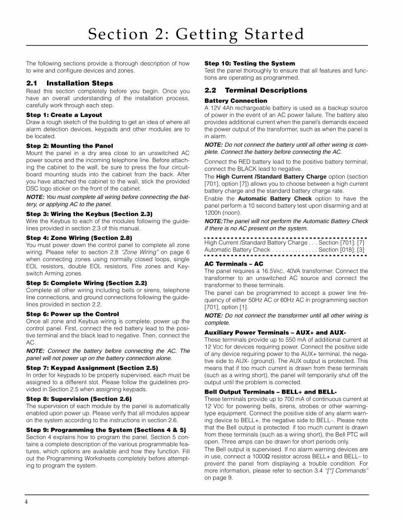
Step 10: Testing the SystemTest the panel thoroughly to ensure that all features and func-tions are operating as programmed.
2.2 Terminal DescriptionsBattery ConnectionA 12V 4Ah rechargeable battery is used as a backup sourceof power in the event of an AC power failure. The battery alsoprovides additional current when the panel’s demands exceedthe power output of the transformer, such as when the panel isin alarm.NOTE: Do not connect the battery until all other wiring is com-plete. Connect the battery before connecting the AC.
Connect the RED battery lead to the positive battery terminal;connect the BLACK lead to negative.The High Current /Standard Battery Charge option (section[701], option [7]) allows you to choose between a high currentbattery charge and the standard battery charge rate.Enable the Automatic Battery Check option to have thepanel perform a 10 second battery test upon disarming and at1200h (noon). NOTE:The panel will not perform the Automatic Battery Checkif there is no AC present on the system.
High Current /Standard Battery Charge . . . Section [701]: [7]Automatic Battery Check . . . . . . . . . . . . . . Section [018]: [3]
AC Terminals – ACThe panel requires a 16.5VAC, 40VA transformer. Connect thetransformer to an unswitched AC source and connect thetransformer to these terminals.The panel can be programmed to accept a power line fre-quency of either 50Hz AC or 60Hz AC in programming section[701], option [1].NOTE: Do not connect the transformer until all other wiring iscomplete.
Auxiliary Power Terminals – AUX+ and AUX-These terminals provide up to 550 mA of additional current at12 VDC for devices requiring power. Connect the positive sideof any device requiring power to the AUX+ terminal, the nega-tive side to AUX- (ground). The AUX output is protected. Thismeans that if too much current is drawn from these terminals(such as a wiring short), the panel will temporarily shut off theoutput until the problem is corrected.
Bell Output Terminals – BELL+ and BELL- These terminals provide up to 700 mA of continuous current at12 VDC for powering bells, sirens, strobes or other warning-type equipment. Connect the positive side of any alarm warn-ing device to BELL+, the negative side to BELL–. Please notethat the Bell output is protected: if too much current is drawnfrom these terminals (such as a wiring short), the Bell PTC willopen. Three amps can be drawn for short periods only.The Bell output is supervised. If no alarm warning devices arein use, connect a 1000Ω resistor across BELL+ and BELL– toprevent the panel from displaying a trouble condition. Formore information, please refer to section 3.4 “[*] Commands”on page 9.

G e t t i n g S t a r t e d : 2 . 3 K e y b u s O p e r a t i o n a n d W i r i n g
5
Keybus Terminals – AUX+, AUX-, YEL, GRN The Keybus is used by the panel to communicate with mod-ules and vice versa. Each module has four Keybus terminalsthat must be connected to the four Keybus terminals on thepanel. For more information, see section 2.3 “Keybus Opera-tion and Wiring”.
Programmable Output Terminals – PGM1 and PGM2Each PGM output is designed so that when activated by thepanel, the terminal will switch to ground.PGM1 can sink up to 300mA ofcurrent. Connect the positiveside of the LED or buzzer toAUX+, the negative side toPGM1. If more than 300 mA ofcurrent are required, a relaymust be used. Please studyPGM wiring in the accompany-ing diagram.PGM2 operates similarly toPGM1. However, PGM2 canonly sink up to 50mA of cur-rent. For a list of the program-mable output options, seesection 5.11 “PGM OutputOptions” on page 22.
Zone Input Terminals – Z1 to Z6Each detection device must be connected to a zone on thecontrol panel. We suggest that one detection device be con-nected to each zone; wiring multiple detection devices to asingle zone, however, is possible. For zone wiring specifics,please see section 2.8 “Zone Wiring” on page 6.
Telephone Connection Terminals – TIP, RING, T-1, R-1If a telephone line is required for central station communica-tion or downloading, connect an RJ-31X telephone jack in thefollowing manner:
Connect the PC5008 and modules which use the telephoneline(s) in the following order:
For example, if you are installing a PC5008 with an Escort5580and a PC5928 Intercom module, connect the incoming line tothe control panel, then to the Escort5580 and then to thePC5928 Intercom. Next, connect the PC5928 to the housetelephones.NOTE: For proper operation, no other telephone equipment should be connected between the control panel and the tele-phone company facilities. Do not connect the alarm panel com-
municator to telephone lines intended for use with a faxmachine. These lines may incorporate a voice filter which dis-connects the line if anything other than fax signals aredetected, resulting in incomplete transmissions.
2.3 Keybus Operation and WiringThe Keybus is used by the panel to communicate with all con-nected modules and vice versa. The red (AUX+) and black(AUX-) terminals are used to provide power, while the yellow(YEL) and green (GRN) terminals are clock and data respec-tively.NOTE: The four Keybus terminals of the panel must be con-nected to the four Keybus terminals or wires of all modules.
The following restrictions apply to Keybus wiring:• Keybus should be run in minimum 22 gauge quad
(0.5mm); two pair twist is preferred. • The modules should be home-run to the panel but can be
connected in series or T-tapped.• Any module can be connected anywhere along the Key-
bus. You do not need to run a separate Keybus wire forkeypads, etc.
• No module can be more than 1,000'/305m (in wire length)from the panel.
• Shielded wire should not be used.
Example of Keybus WiringNOTE: Module (A) is correctlywired within 1,000'/305m of wire from thepanel.Module (B) is correctlywired within 1,000'/305m of wire from thepanel.Module (C) is NOT wired correctly as it is further than 1,000'/305m from the panel, in wire distance.
2.4 Current Ratings – Modules and Accessories
In order for the PC5008 system to operate properly, the poweroutput capabilities of the main control and the expansiondevices must not be exceeded. Use the data presented belowto ensure that no part of the system is overloaded and cannotfunction properly.
PC5008 (12 VDC)AUX+: ........550mA: Subtract the listed rating for each key-
pad, expansion module and accessory con-nected to AUX+ or Keybus.
BELL: .........700mA continuous rating; 3.0A short term. Avail-able only with standby battery connected.
PC5008 Device Ratings (at 12 VDC)• LCD5500Z Keypad: 85mA• PC5508Z Keypad: 85mA• PC5400 Serial Module: 65mA• Escort5580 Audio Assistant: 65mA standby / 130mA on-
line• PC5204 High Current Output module: 20mA• PC5208 Low Current Output module: 50mA• PC5132 Wireless Receiver: 125mA• PC5928 Audio Interface module: 65mA• PC5921/EXT Door Box Audio Station: 20mA• PC59X1EXT/R Door Box Audio Station: 35mA
6
• PC5904 Central Station Talk/Listen Module: 30mAstandby, 130mA max.
Other DevicesPlease read the manufacturer’s literature carefully to deter-mine the maximum current requirements for each device—during activation or alarm—and include the proper values forloading calculations. Connected devices must not exceedsystem capabilities during any possible operational mode.
2.5 Keypad AssignmentThere are eight available slots for keypads. LED keypads bydefault are always assigned to slot 1. LCD5500Z keypads arealways assigned to slot 8. You will need to assign each key-pad to its own slot (1 to 8). Keypad assignment is required, asit tells the panel which slots are occupied. The panel can thengenerate a fault when a keypad supervisory is not present. NOTE: One LCD keypad must be assigned to slot 8 in order toupload keypad programming using DLS-1 software.
How to Assign KeypadsDo the following at each keypad installed on the system:1. Enter [*][8][installer’s code] to go to installer programming2. Enter [000] for Keypad Programming3. Enter [0] for Slot Assignment4. Enter a two digit number (11-18) to specify which supervi-
sory slot the keypad will occupy. 5. Press [#] twice to exit installer programming. After assigning all keypads, perform a supervisory reset byentering section [902] in installer’s programming. The panelwill now supervise all assigned keypads and enrolled moduleson the system.
How to Program Function KeysBy default, the 5 function keys on each LCD5500Z keypad areprogrammed as Stay Arm (03), Away Arm (04), Chime (06),Sensor Reset (14) and Quick Exit (16). By default, the firstthree function keys on each PC5508Z, PC5516Z, andPC5532Z keypad are programmed as Away Arm (04), StayArm (03), and Sensor Reset (14). The last two function keysare programmed as null keys (00). You can change the func-tion of each key on every keypad:1. Go to the keypad where you want to change the function
key programming and enter Installer Programming.2. Press [000] for Keypad Programming. 3. Enter [1] to [5] to select a function key to program. 4. Enter the 2 digit number, [00] to [21] to select the feature
you want the function key to have. For a complete list ofFunction Key options see section 3.5 “Function Keys” onpage 12.
5. Continue from step 3 until all function keys are pro-grammed.
6. To exit Installer Programming, press [#] twice.
2.6 SupervisionBy default, all modules are supervised upon installation.Supervision is enabled at all times so that the panel can indi-cate a trouble if a module is removed from the system.To check which modules are currently connected and super-vised, at an LCD keypad enter programming section [903]from installer’s programming. The keypad will allow you toscroll through the display of connected modules. A connectedmodule which does not show as being present will appear asa trouble condition and the Trouble light on the keypad willturn ON. This condition may be due to one or more of the fol-lowing reasons:• the module is not connected to the Keybus
• there is a Keybus wiring problem • the module is more than 1,000'/305m from the panel • the module does not have enough powerFor more information regarding module supervision troubles,please refer to “[*][2] Trouble Display” on page 10.
2.7 Removing ModulesThe panel must be instructed to no longer supervise a modulebeing removed from the system. To remove the module, dis-connect it from the Keybus and reset the supervision field byentering [902] in the installer’s programming. The panel will bereset to recognize and supervise all existing modules on thesystem.
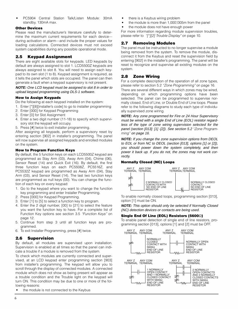
2.8 Zone WiringFor a complete description of the operation of all zone types,please refer to section 5.2 “Zone Programming” on page 16.There are several different ways in which zones may be wired,depending on which programming options have beenselected. The panel can be programmed to supervise nor-mally closed, End of Line, or Double End of Line loops. Pleaserefer to the following diagrams to study each type of individu-ally supervised zone wiring. NOTE: Any zone programmed for Fire or 24 Hour Supervisorymust be wired with a single End of Line (EOL) resistor regard-less of the type of zone wiring supervision selected for thepanel (section [013]: [1] -[2]). See section 5.2 “Zone Program-ming” on page 16.
NOTE: If you change the zone supervision options from DEOLto EOL or from NC to DEOL (section [013], options [1] or [2]),you should power down the system completely, and thenpower it back up. If you do not, the zones may not work cor-rectly.
Normally Closed (NC) Loops
To enable normally closed loops, programming section [013],option [1] must be ON.NOTE: This option should only be selected if Normally Closed(NC) detection devices or contacts are being used.
Single End Of Line (EOL) Resistors (5600Ω)To enable panel detection of single end of line resistors, pro-gramming section [013], options [1] and [2] must be OFF.
G e t t i n g S t a r t e d : 2 . 9 F i r e Z o n e W i r i n g
7
NOTE: This option should be selected if either NormallyClosed (NC) or Normally Open (NO) detection devices or con-tacts are being used.
Double End of Line (DEOL) ResistorsDouble End of Line resistors allow the panel to determine if thezone is in alarm, tampered or faulted. To enable panel detection of double end of line resistors, pro-gramming section [013], option [1] must be OFF and option[2] must be ON. With DEOL selected, if the system is disarmed, the keypadbuzzers will activate when a fault or tamper occurs. Manuallybypassed zones will not show alarm, fault, or tamper condi-tions.Wire DEOL zones according to the following diagram:
NOTE: Do not wire DEOL resistors on keypad zones. Do notuse DEOL resistors for Fire zones or 24 Hour Supervisoryzones.
NOTE: The DEOL option can only be selected if NormallyClosed (NC) detection devices or contacts are being used. Only one NC contact can be connected to each zone. Wiringmultiple detection devices or contacts on a single loop is notallowed.
NOTE: If the DEOL supervision option is enabled:
• All hardwire zones on the main panel must be wired forDouble EOL resistors, except for Fire and 24 Hour Supervi-sory zones.
• Do not wire Fire zones to keypad zone terminals.
The following chart shows zone status under certain condi-tions:
Loop Resistance Loop Status0Ω (shorted wire, loop shorted) Fault
5600Ω (contact closed) SecureInfinite (broken wire, loop open) Tamper
11200Ω (contact open) Violated
End of Line Resistors . . . . . . . . . . . . . . . . . Section [013]: [1]Double End of Line Resistors . . . . . . . . . . . Section [013]: [2]
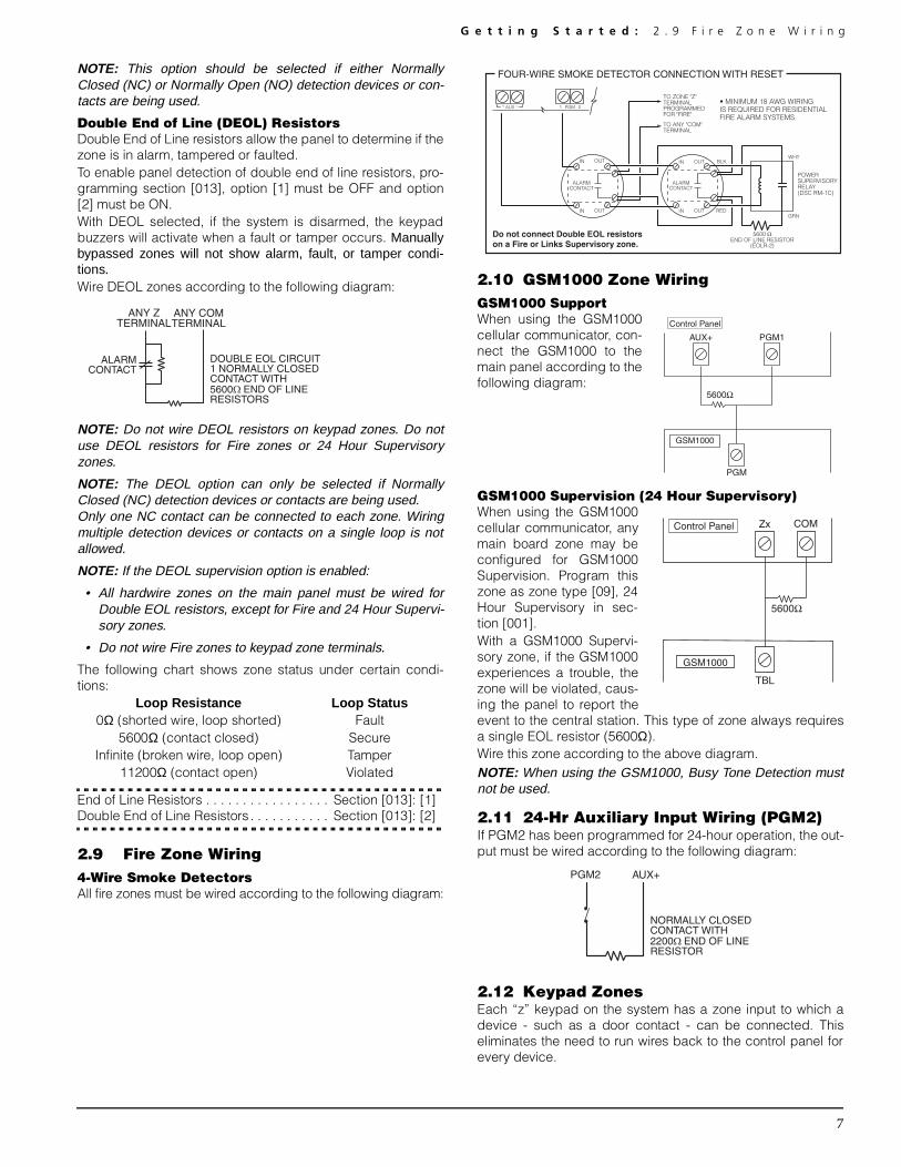
2.9 Fire Zone Wiring 4-Wire Smoke DetectorsAll fire zones must be wired according to the following diagram:
2.10 GSM1000 Zone WiringGSM1000 SupportWhen using the GSM1000cellular communicator, con-nect the GSM1000 to themain panel according to thefollowing diagram:
GSM1000 Supervision (24 Hour Supervisory)When using the GSM1000cellular communicator, anymain board zone may beconfigured for GSM1000Supervision. Program thiszone as zone type [09], 24Hour Supervisory in sec-tion [001].With a GSM1000 Supervi-sory zone, if the GSM1000experiences a trouble, thezone will be violated, caus-ing the panel to report theevent to the central station. This type of zone always requiresa single EOL resistor (5600Ω).Wire this zone according to the above diagram.NOTE: When using the GSM1000, Busy Tone Detection mustnot be used.
2.11 24-Hr Auxiliary Input Wiring (PGM2)If PGM2 has been programmed for 24-hour operation, the out-put must be wired according to the following diagram:
2.12 Keypad ZonesEach “z” keypad on the system has a zone input to which adevice - such as a door contact - can be connected. Thiseliminates the need to run wires back to the control panel forevery device.

8
To install the keypad, open the keypad plastic by removing thescrew at the bottom of the unit. Locate the five terminals onthe keypad circuit board. Connect the four Keybus wires fromthe control panel: the red wire to R, the black to B, the yellowto Y and the green to G.To connect the zone, run one wire to the Z terminal and theother to B. For powered devices, use red and black to supplypower to the device. Run the red wire to the R (positive) termi-nal and the black wire to the B (negative) terminal. When using end of line supervision, connect the zone accord-ing to one of the configurations outlined in section 2.8 “ZoneWiring” on page 6. End of line resistors must be placed on thedevice end of the loop, not at the keypad.NOTE: Keypad zones do not support DEOL resistors.
Assigning Keypad ZonesWhen using keypad zone inputs, each input used must beassigned a zone number in Installer’s Programming. First, ensure that you have enrolled all installed keypads intothe desired slots. (See section 2.5 “Keypad Assignment” onpage 6.)Next, enter programming section [020] to assign the zones.There are eight programming locations in this section, one foreach keypad slot. Enter a 2-digit zone number for each of thekeypad zones. This number must be entered in the locationcorresponding to the keypad to which each zone is con-nected. Example : The zone on an LCD5500Z keypad in slot 8 is to beassigned zone 3. In section [020], scroll to option [8] andenter (03).NOTE: Keypad zones 1-6 will replace zone terminals Z1-Z6 onthe control panel.
NOTE: Once the keypad zones are assigned, you must alsoprogram zone definitions and zone attributes. (See also sec-tion 5.4 “Assigning Keypad Zones” on page 18.)
NOTE: Keypad zones cannot be used for 24 Hour Supervisory.

9
Section 3: Keypad Commands
Use any system keypad to enter commands and/or programthe PC5008 security system. The LED keypad uses functionand zone indicator lights to represent alarm functions and sta-tus. The LCD keypad provides a written description on the liq-uid crystal display and uses function indicator lights tocommunicate alarm status to the user.The PC5008 Instruction Manual provides basic directions forarming and disarming the system, bypassing zones and per-forming user functions from the keypads. The following sec-tions provide additional details on these functions.
3.1 Arming and DisarmingFor a description of basic arming and disarming, please seethe PC5008 Instruction Manual. For other methods of arming,please refer to section 3.4 “[*] Commands” and section 3.5“Function Keys” on page 12.NOTE: The Event Buffer will log “Armed in Stay Mode” or“Armed in Away Mode” whenever the system is armed.
In an attempt to prevent false alarms, the Audible Exit Faultwill notify the user of an improper exit when they arm their sys-tem. If a non force-arming Delay 1 or Delay 2 type zone is leftopen at the end of the exit delay, the entry delay will beginimmediately and the bell or siren will sound a steady alarm forthe entry delay period. At the end of the entry delay period, ifthe system has not been disarmed it will go into alarm. Thisfeature can be turned OFF in programming section [013],option [6]. (See section 5.17 “Arming/Disarming Options” onpage 25 for more information.)
3.2 Auto Bypass – Stay ArmingStay arming allows the user to arm the system without leavingthe premises. All zones programmed as stay/away will bebypassed when the user stay arms the system, so that theuser does not have to bypass interior zones manually. (Seesection 5.2 “Zone Programming” on page 16.)When the system is armed using a valid access code, if anyzones on the system have been programmed as stay/awayzones, the Bypass light will turn ON. The panel will then moni-tor all zones programmed as Delay 1 and Delay 2 zones, suchas designated entry/exit doors. If a delay zone is not violatedby the end of the exit delay, the panel will bypass all stay/awayzones. The Bypass light will remain on to inform the user thatthe interior zones have been automatically bypassed by thepanel. If a delay zone is violated during the exit delay, the sys-tem will arm in Away mode and all stay/away zones will beactive after the exit delay expires.The user can arm the stay/away zones at any time by enteringthe [*][1] keypad command (see “[*][1] Bypassing and Acti-vating Stay/Away Zones”).Stay arming can also be initiated by pressing and holding theStay function key for two seconds on the PC5508Z andLCD5500Z keypads, if programmed. For more informationregarding Stay arming, please see section 3.5 “FunctionKeys” on page 12.
3.3 Automatic ArmingThe system can be programmed to Auto-Arm at a specifictime every day if it is in the disarmed condition. In order for theAuto-Arm function to work properly, you must program the cor-
rect Time of Day. For programming the clock and auto-armtimes, see “[*][6] User Functions” on page 11.When the system’s internal clock matches the Auto-Arm Time,the panel will check the system status. If the system is armed,the panel will do nothing until the next day at the auto-arm time,when it will check the system again. If the system is disarmed atthe auto-arm time, the panel will sound the buzzer of all key-pads for five minutes. If the Bell Squawk During Auto Armoption is enabled (section [014], option [2]), the bell will squawkonce every 10 seconds while the system is auto-arming. Users can postpone auto-arming for two hours by entering avalid access code. If auto-arming is postponed, the systemwill log the number of the user who postponed the arming inthe event buffer and, if programmed, transmit an Auto-armCancel/Postpone event. After two hours, the system will attempt to auto-arm again. Thesystem will continue to try to auto-arm two hours after eachpostponement until the panel is armed, either automatically ormanually. NOTE: If one of the following trouble events prevent the systemfrom arming, the panel will transmit an Auto Arm Cancellationreporting code (if programmed): AC/DC Inhibit Arm, LatchingSystem Tampers, Zone Expander Supervisory Fault
If no access code is entered during the five-minute warningperiod, the panel will auto-arm. If a zone is violated duringauto-arming, the panel will transmit a Partial Closing Report-ing Code – if programmed – to indicate to the central stationthat the system is not secure. If the zone is restored, the panelwill add the zone back into the sytem.NOTE: Auto-arming can only be postponed by entering a valid access code at a system keypad.
3.4 [*] CommandsThe [*] key commands provide an easy way for the user toaccess basic system programming – such as programmingaccess codes or bypassing zones. The user can also use the[*] key commands to check on the system’s status, includingviewing trouble conditions and displaying the event buffer onthe LCD keypad.The [*] key commands can be performed from both LCD andLED keypads. The LED keypad uses the zone indicator lightsto display command information. The LCD display provideswritten information, guiding the user through each command.The commands in this section are explained as viewed froman LED keypad. When using an LCD keypad, use the arrowkeys (< >) to scroll through information provided. Otherwise,the functions remain the same for both keypad types.
[*][1] Bypassing and Activating Stay/Away ZonesUse the [*][1] keypad command to bypass individual zones. Abypassed zone will not cause an alarm. NOTE: Zones can only be bypassed when the system is notarmed. If DEOL is used, manually bypassed zones will notshow alarm, fault, or tamper conditions.
If the Code Required for Bypass option is enabled (section[015], option [5]), only access codes with the bypass attributeenabled will be able to bypass zones (see section 5.1 “Pro-gramming Security Codes” on page 16).

10
If the Bypass Status Displayed While Armed option is cho-sen, the Bypass light will be ON while the system is armed toindicate any bypassed zones (see section 5.17 “Arming/Dis-arming Options” on page 25).NOTE: When you disarm the system, all manually-bypassedzones will be unbypassed.
Activate Stay/Away ZonesIf the system is armed in stay mode, the [*][1] command canbe used to activate the stay/away zones.
[*][2] Trouble Display The panel constantly monitors itself for several different trou-ble conditions. If a trouble condition is present, the Troublelight will be on and the keypad will beep twice every 10 sec-onds. When the system is disarmed, users can silence thetrouble beep for faults and tampers by entering an accesscode. For other troubles, users can silence the trouble beepby pressing any key at any system keypad.
If Bell Squawk on Trouble is enabled (section [014], option[5]), the bell will squawk every 10 seconds when a troublecondition is present.If the Troubles are Latching option is enabled, when a troublerestores before a user has viewed it (via [*][2]), the Trouble LEDwill stay on (latch). Once a user has viewed the trouble, the LEDwill turn off (unless other troubles are present on the system). NOTE: If the panel fails to communicate in Residential Dialmode, the FTC trouble will not latch.
Bell Squawk on Trouble . . . . . . . . . . . . . . . Section [014]: [5]Troubles are Latching . . . . . . . . . . . . . . . . . Section [018]: [1]AC Trouble Beeps. . . . . . . . . . . . . . . . . . . . Section [018]: [5]
To view trouble conditions from an LED keypad:1. Press [*][2]. 2. The keypad flashes the Trouble light. The zone indicator lights
corresponding to the present trouble conditions are ON.The various troubles are described below:
Light Trouble
1 Service Required: Press [1] to determine the specific trouble. Lights 1 - 8 will light up to indicate the trouble:• Light [1] Low Battery: Main panel backup battery charge is low (below 11.5 volts under load).Trouble is restored
when the battery charges over 12.5 volts.• Light [2] Bell Circuit Trouble: The bell circuit is open (see section 5.13 “Bell” on page 24).• Light [3] General System Trouble: The PC5204 Power Supply module has an AUX failure, PC5204 Output #1 Trouble,
or a printer connected to the PC5400 Printer module has a fault and is off-line.• Light [4] General System Tamper: Tamper has been detected in a module.• Light [5] General System Supervisory: The panel has lost communication with a module connected to the Keybus
(see section 2.6 “Supervision” on page 6). The event buffer will log the event. NOTE: All tamper conditions must be physically restored before the trouble condition will clear.
• Light [6] – Not used• Light [7] PC5204 Low Battery: The PC5204 module has a low backup battery.• Light [8] PC5204 AC Failure: The PC5204 module has lost AC power.NOTE:If you remove and then restore power to the main panel in order to service any PC5204 module, or any modulebeing powered by a PC5204, you must also remove and then restore power to the PC5204 and any connected modules.This ensures that any troubles present on the module are correctly logged and/or annunciated.
2 AC Failure: AC power is no longer being supplied to the control panel. The Trouble light will flash if an AC Failure ispresent, if the Trouble Light Flashes if AC Fails option is programmed (section [016], option [2]). This trouble will notbe displayed if the AC Trouble Displayed option is disabled (section [016], option [1]). If the AC Trouble Beeps optionis off, keypads will not sound trouble beeps if an AC trouble occurs (section [018], option [5]). See section 5.8 “Communicator – Reporting Codes” on page 19 for information on AC trouble reporting.
3 Telephone Line Monitoring Trouble (TLM): There is a problem with the telephone line (See section 5.12 “Tele-phone Line Monitor (TLM)” on page 24.)
4 Failure to Communicate (FTC): The communicator failed to communicate with any of the programmed telephonenumbers (see section 5.5 “Communicator – Dialing” on page 18).
5 Zone Fault (including Fire Zone): A zone on the system is experiencing trouble, meaning that a zone could notprovide an alarm to the panel if required to do so (e.g. a fire zone is open, or there is a short on a DEOL zone, or a super-visory fault on a wireless zone). When a zone fault trouble condition occurs, the keypad(s) on the system will start tobeep. Press [5] while in Trouble mode to view the affected zones.NOTE: A Fire zone trouble will be generated and displayed in the armed state.
6 Zone Tamper: A zone configured for Double End Of Line resistor supervision has a tamper condition, or the tamperswitch is open on a wireless device. When a tamper condition occurs, the keypad(s) will start to beep. Press [6] while in theTrouble mode to view the affected zones. If a zone is tampered or faulted, it must be fully restored to clear the trouble.NOTE: By enabling Tampers/Faults Do Not Show as Open in section [013], option [4], Faults and Tampers will not showas open on the keypad, and will be hidden from the end user. If the option is disabled, Faults and Tampers will be dis-played on the keypad
NOTE:Once a zone is tampered or faulted, it must be completely restored before the trouble condition will clear.7 Device Low Battery: A wireless device has a low battery condition. Press [7] one, two, or three times to view which
devices are experiencing battery failure. An LED keypad will indicate battery failure using zone lights 1 to 8. The follow-ing will occur:
Keypad beeps: Keypad displays:Press [7] 1 Zones with low batteries (LED keypad - zone lights 1 to 8)Press [7] again 2 Handheld keypads with low batteries (LED keypad - zone lights 1 to 4)Press [7] again 3 Wireless keys with low batteries (LED keypad - zone lights 1 to 8)
To view the battery conditions of wireless keys 9 through 16, you must use an LCD keypad.8 Loss of System Time: When the panel is powered up, the internal clock needs to be set to the correct time. This
trouble is cleared when an attempt is made to reset the clock.

K e y p a d C o m m a n d s : 3 . 4 [ * ] C o m m a n d s
11
To view trouble conditions from an LCD keypad:When using an LCD keypad, press [*][2]. The trouble condi-tions will be listed on the display. Use the arrow (< >) keys toscroll through the list of present trouble conditions.NOTE: Troubles can be viewed while armed using the LCDkeypad, provided the keypad is version 2.0 or later. Older key-pads will incorrectly display “Fire Trouble”. If using older LCDkeypads, programming section [013], option [3] as OFF willensure troubles are displayed correctly.
[*][3] Alarm MemoryThe Memory light will be on if any alarm occurred during thelast armed period or – in the case of 24 hour zones – if analarm occurred while the panel was disarmed.To view alarm memory, press [*][3]. The keypad will flash theMemory light and the zone indicator lights corresponding tothe alarm or tamper conditions which occurred during or sincethe last armed period. To clear the Memory light, arm and dis-arm the system.
[*][4] Door Chime On/OffThe door chime feature is used to sound a tone from the key-pad whenever a zone programmed as a chime zone is acti-vated (see section 5.3 “Zone Attributes” on page 17). If thedoor chime feature is enabled, the keypad will emit five shortbeeps whenever a chime zone is activated. Designated entry/exit doors are often defined as chime zones. The feature canbe turned on or off while the system is armed or disarmed.
[*][5] Programming Access CodesThere are 37 access codes available to the user. They are:Access code (40) ......................One master code Access codes (01)-(32).............32 general access codesAccess codes (33)-(34).............Two duress codesAccess codes (41)-(42).............Two supervisor codesAll access codes have the ability to arm or disarm the systemand can activate the PGM Outputs using the [*][7] com-mands. Access codes can be either four or six digits (seesection 5.1 “Programming Security Codes” on page 16).For a description of how to program access codes from LCDor LED keypads, see the PC5008 Instruction Manual.
Master Code – Access Code (40)By default, the Master Code is enabled to perform any keypadfunction. This code can be used to program all access codes.If the Master Code Not Changeable option is enabled (sec-tion [015], option [6]), the Master Code can only be changedby the Installer.
General Access Codes – Access Codes (01) to (32)General access codes can arm and disarm the system. Whenthe Code Required for Bypassing option is enabled, userswill need to enter a valid access code when bypassing zones.Individual access codes can have the Zone Bypassingattribute disabled under Access Code Attribute programming.For more information regarding access code options, pleasesee section 5.1 “Programming Security Codes” on page 16.
Duress Code – Access Code (33) and (34)Duress codes will send a duress reporting code to the centralstation when entered. NOTE: If a duress code is programmed, when it is used, the panel will always send a reporting code to the central station,even if the attributes of the duress code are turned off.
Supervisor Codes – Access Code (41) and (42)These codes can be used to program general access andduress codes. The two supervisor codes have master codeattributes by default. These settings can be changed.
Access Code AttributesThere are four access code attributes which can be pro-grammed for each code. NOTE: Master code attributes cannot be changed.
To program attributes for a code:1. Enter [*][5][Master Code][9] 2. Enter the code number [01-32,33,34,41,42]. 3. Enter the attribute number to toggle the attribute on or off:Attribute [1] ......User enabled for arming, disarming, alarm
reset, [*][7][1-4] options, auto arm cancella-tion
Attribute [2] ......Not usedAttribute [3] ......Zone bypassing enabledAttribute [4] ......Escort5580 access enabledAttributes [5-7] .Not usedAttribute [8] ......One-time use code (access codes 01-16
only). NOTE:You should have attribute [1] enabled for all accesscodes in use.
One-time Use CodesIf the panel is disarmed with a one-time use code, the codewill be erased at the end of the exit delay the next time thepanel is armed. The code will also be erased at the end of theExit Delay when used to arm the panel. If the panel is armed with a one-time use code, but anotheruser enters a valid access code during the exit delay, the one-time use code will not be erased and can still be used to armthe panel one time.
[*][6] User FunctionsThis command can be used to program several different func-tions:
To Program User Functions:1. Press [*][6][Master Code]. The Program light will flash. 2. Press the number [1] to [7] for the item to be programmed.• [1] – Time and Date
The time and date must be accurate for the auto-arm ortest transmission functions to work properly and for theevent buffer to time and date stamp all events.- Enter the time (hour and minute) using 24hr format [HHMM] from 00:00 to 23:59.- Enter the date by month, day and year [MM DD YY].
• [2] – Auto-Arm Enable/DisableTo enable or disable auto-arming, press [2]. The keypadwill sound three short beeps when auto-arm is enabledand one long beep when disabled. For more information,see section 3.3 “Automatic Arming” on page 9.
• [3] – Auto-Arm TimeThe system can be programmed to arm automatically at apre-set time. When programming the auto-arm time, enterthe time (hour and minute) using 24hr format [HH MM].For more information, see section 3.3 “Automatic Arming”on page 9.
• [4] – System TestWhen [4] is pressed the panel will test the bell output,keypad lights and the communicator for two seconds.The panel will also send a System Test Reporting code, if

12
programmed (see section 5.8 “Communicator – Report-ing Codes” on page 19).
• [5] – Enable DLS (Downloading)When [5] is pressed, the panel will enable the download-ing option for one or six hours depending on the optionselected in programming section [702]: [7]. During thistime, the panel will answer incoming downloading calls(see section 5.10 “Downloading” on page 21).
• [6] – User Initiated Call-UpWhen [6] is pressed, the panel will initiate a call to thedownloading computer.
• [7] - Enable Background MusicIf enabled on the PC59XX Audio Interface Module, when[7] is pressed, the user can turn background music On orOff.
Additional Features Available from the LCD KeypadAdditional features, including access to the event buffer, areavailable using the LCD keypad. Use the arrow keys (< >) toscroll through the [*][6] menu and press the [*] key to selectthe following commands:
Viewing the Event Buffer from an LCD KeypadSelect “View Event Buffer” from the [*][6] menu. The keypadwill display the event, event number, time and date along withthe zone number and access code, if applicable. Press [*] totoggle between this information and the event itself. Use thearrow keys (<>) to scroll through the events in the buffer.When you have finished viewing the event buffer, press [#] toexit.
Brightness ControlYou can select from 10 different backlighting levels. Use thearrow keys (< >) to scroll to the desired backlighting level.Press [#] to exit.
Contrast ControlYou can select from 10 different display contrast levels. Usethe arrow keys (< >) to scroll to the desired contrast level.Press [#] to exit.
Keypad Sounder ControlYou can select from 21 different keypad tones. Use the arrowkeys (< >) to scroll to the desired keypad sound level andpress [#] to exit. This feature can be accessed on LED key-pads by pressing and holding the [*] key.
[*][7] Command Output FunctionsThe user can activate programmable output functions usingthe [*][7][1-4] commands. The outputs may be activated whenthe system is either armed or disarmed.
Command Output Options 1-4:Press [*][7][1-4][Access Code, if required] to activate outputsprogrammed as PGM output option [19]-[22]. These outputscan be used for operating devices such a garage dooropener, lighting or door strikes.
[*][7][2] – Command Output Option #2:Press [*][7][2][Access Code, if required] to activate all outputsprogrammed as one of PGM output options [03] or [20]. Special Note: Traditionally, [*][7][2] has been reserved forresetting smoke detectors. Smoke detectors should now beprogrammed as output [03] “Sensor Reset”. If using outputoption [03], do not program [20] Command Output Option #2.Please see section 5.11 “PGM Output Options” on page 22 formore information.
[*][8] Installer’s ProgrammingEnter [*][8] followed by the Installer’s Code to accessInstaller’s Programming. See sections 4 and 5 for more infor-mation.
[*][9] Arming Without Entry DelayWhen the system is armed with the [*][9] command, the panelwill cancel the entry delay. Delay 1 and Delay 2 type zones willbe instant and Stay/Away zones will be bypassed as soon asthe exit delay has ended (see section 5.2 “Zone Program-ming” on page 16). The user must enter a valid access codeafter pressing [*][9].
[*][0] Quick ArmIf the Quick Arm option is enabled, enter [*][0] to arm thepanel without an access code (See section 5.17 “Arming/Dis-arming Options” on page 25). NOTE: Quick Arm cannot be used to cancel auto arm.
[*][0] Quick ExitThe Quick Exit function, if enabled, will allow someone toleave an armed premises through a Delay type zone withouthaving to disarm and re-arm the system (See section 5.17“Arming/Disarming Options” on page 25).When [*][0] is entered, the panel will provide a two minute win-dow for the user to exit the premises. During this time, thepanel will ignore only one activation of a Delay zone. When theDelay zone is secured, the panel will end the two minute quickexit delay.If a second Delay zone is tripped, or if the zone is not restoredafter two minutes, the panel will begin the entry delay.NOTE: If the Exit Delay is in progress, performing a Quick Exitwill not extend the Exit Delay.
3.5 Function KeysThere are five function keys on each keypad. On LCD550Z key-pads, the function keys are programmed by default as Stay,Away, Chime, Reset and Exit. On PC5508Z, PC5516Z, andPC5532Z keypads, three of the keys are programmed by defaultas Away, Stay, and Reset. The other two keys are not pro-grammed with a function. Press and hold the appropriate key fortwo seconds to activate a function.
“Stay” – (03) Stay ArmThe system will arm in the Stay mode (see section 3.2 “AutoBypass – Stay Arming” on page 9). Enable the Quick Arm fea-ture (programming section [015], option [4]) to have this keyfunction without the need to enter an access code. If QuickArm is not enabled, the user will have to enter an access codebefore the system will stay arm.
“Away” – (04) Away ArmThe system will arm in the Away mode (see section 3.2 “AutoBypass – Stay Arming” on page 9). Enable the Quick Arm fea-ture (programming section [015], option [4]) to have this keyfunction without the need to enter an access code. If QuickArm is not enabled, the user will have to enter an access codebefore the system will away arm.
“Chime” – (06) Door Chime On / OffThe Door Chime feature will turn ON or OFF (see “[*][4] DoorChime On/Off” on page 11).
“Reset” – (14) Sensor Reset or [*][7][2]The panel will activate all PGM outputs programmed as option[03] Sensor Reset or [20] Command Output Option #2. (See“[*][7] Command Output Functions” on page 12).

K e y p a d C o m m a n d s : 3 . 6 F e a t u r e s A v a i l a b l e f o r t h e L C D 5 5 0 0 Z
13
“Exit” – (16) Activate Quick ExitThe panel will activate the Quick Exit feature (See section 3.4“[*] Commands” on page 9).
Additional Function Key OptionsThe programming of any function key on any keypad may bechanged to one of the options listed below. (See section 2.5“Keypad Assignment” on page 6 for instructions on changingfunction key programming.) Each option is listed according tothe programming code, followed by the corresponding [*] keycommand. For more information regarding each function,please refer to the appropriate part of section 3.4 “[*] Com-mands” on page 9.[00] Null Key: The key is not used and will perform no
function when pressed.[01]-[02] For future use[03] Stay Arm: As described above.[04] Away Arm: As described above.[05] [*][9] No-Entry Delay Arm: A valid access code must
also be entered.[06] [*][4] Door Chime On / Off[07] [*][6][----][4] System Test: A valid master code must
also be entered.[08] [*][1] Bypass Mode: A valid access code may need
to be entered.[09] [*][2] Trouble Display[10] [*][3] Alarm Memory[11] [*][5] Programming Access Codes: A valid master
code must also be entered.[12] [*][6] User Functions: A valid master code must also
be entered.[13] [*][7][1] Command Output Option #1: A valid access
code may need to be entered.[14] [*][7][2] Reset (Command Output Option #2): As
described above.[15] General Voice Prompt Help: This feature can only be
programmed if both the Escort5580 and the PC5928Audio Matrix module are being used. The intercomswill perform a Help page. The user must then pressthe Page/Answer button on any intercom station tobegin the help session with the Escort.
[16] [*][0] Quick Exit[17] [*][1] Reactivate Stay/Away Zones[18] Identified Voice Prompt Help: Can only be pro-
grammed if both the Escort5580 and the PC5928Audio Matrix module are being used. The Escort willbegin a help session from the intercom station clos-est to the keypad. You must also program PC5928Section [802], subsection [14] “Keypad Port Assign-ments.” For more information, please refer to thePC5928 Installation Manual.
NOTE:This function key cannot be programmed for PC55XX LED keypads with software version 1.0.
[19] [*][7][3] Command Output Option #3: A validaccess code may need to be entered.
[20] For future use[21] [*][7][4] Command Output Option #4: A valid
access code may need to be entered.
3.6 Features Available for the LCD5500Z These features are only available for LCD5500Z keypads withzone inputs:
Automatic Scrolling of Alarms in MemoryThe LCD5500Z keypad allows automatic scrolling throughalarms in memory while the keypad is idle. This feature, ifenabled, will override the clock display. This option can beprogrammed in LCD programming section [66], option [4].
24 Hour Time Display OptionEach LCD5500Z can be programmed to display time using a24-hour clock, instead of a 12-hour, am/pm clock. Programthis option in LCD programming section [66], option [3].
Keypad ZonesSee section 2.12 “Keypad Zones” on page 7.
Viewing Troubles While ArmedSee section “[*][2] Trouble Display” on page 10 for informa-tion on how to view troubles.
Backlighting BoostThe LCD5500Z and PC5508Z zone input keypads will provideextra number pad lighting when any key is pressed. The back-lighting boost will last for an additional 30 seconds after thelast keypress.

14
Section 4: How to Program
The following section of the manual describes the Installer’sProgramming function and how to program the various sec-tions.NOTE: Read the following section of the manual very carefullybefore you begin programming. We also recommend filling outthe Programming Worksheets section before you program thepanel.
For your reference, the corresponding programming sectionsfor the functions listed are highlighted in text boxes such asthis one.
4.1 Installer’s ProgrammingInstaller’s Programming is used to program all communicatorand panel options. The Installer’s Code is [5555] by defaultbut should be changed to prevent unauthorized access toprogramming.
Installer’s Code . . . . . . . . . . . . . . . . . . . . . . . . Section [006]
From an LED Keypad:1. Enter [*][8][Installer’s Code].
The Program light will flash to indicate that you are in pro-gramming mode.The Armed light will turn on to indicate that the panel iswaiting for the three-digit programming section number.
2. Enter the three-digit section number corresponding to thesection you wish to program.The Armed light will turn off.The Ready light will turn on to indicate that the panel iswaiting for the information required to complete program-ming the selected section.
3. Enter the information required to complete section pro-gramming (i.e.: numbers, HEX data, or ON/OFF options).
NOTE: If the three-digit section number entered is invalid, or ifthe module which pertains to the section is not present, thekeypad will sound a two second error tone.
From an LCD Keypad:1. From any keypad, enter [*][8][Installer’s Code]. The Key-
pad will display ‘Enter Section’ followed by three dashes.2. Enter the three-digit number corresponding to the pro-
gramming section number you wish to program. The key-pad will now display the information required to completeprogramming the selected section.
3. Enter the information required to complete section pro-gramming (i.e.: numbers, HEX data, or ON/OFF options).
If you enter information into a section and make a mistake,press the [#] key to exit the section. Select that section againand re-enter the information correctly.NOTE: There must be one digit in each box in the program-ming section in order for the change to be valid.
4.2 Programming Decimal DataA set number of programming boxes are allotted for each sec-tion requiring decimal data (e.g.: codes, telephone numbers).If a digit is entered for each program box, the panel will auto-matically exit from the selected programming section. TheReady light will turn OFF and the Armed light will turn ON.On the PC5508Z keypads, you can also press the [#] key toexit a programming section without entering data for everybox. This is handy if you only need to change digits in the firstfew programming boxes. All other digits in the programmingsection will remain unchanged.
4.3 Programming HEX DataOn occasion, hexadecimal (HEX) digits may be required. Toprogram a HEX digit press the [*] key. The panel will enterHEX programming and Ready light will begin to flash.The following are the numbers which should be pressed toenter the appropriate HEX digit:
1 = A 2 = B 3 = C 4 = D 5 = E 6 = FOnce the correct HEX digit has been entered, the Ready lightwill continue to flash. If another HEX digit is required, press thecorresponding number. If a decimal digit is required, press the[*] key again. The Ready light will turn on and the panel willreturn to regular decimal programming.
Example: To enter ‘C1’ for a closing by user 1, you would enter:
[*][3][*], [1]:• [*] to enter Hexadecimal mode (Ready light flashes) • [3] to enter C• [*] to return to decimal mode (Ready light is solid)• [1] to enter digit 1NOTE: If Ready light is flashing, any number you enter will beprogrammed as the HEX equivalent.
If you are using a pulse communications format, a decimalzero [0] does not transmit. Programming a zero [0] tells thepanel not to send any pulses for that digit. Decimal zero [0] isa filler digit. To transmit a zero [0], it must be programmed asa Hexadecimal ‘A’.
Example: For the three digit account number ‘403’, you would enter:
[4], [*][1][*][3], [0]:• [4] to enter the digit 4• [*] to enter Hexadecimal mode (Ready light flashes)• [1] to enter A• [*] to return to decimal mode (Ready light is solid)• [3] to enter the digit 3• [0] to enter the digit 0 as a filler digit.

H o w t o P r o g r a m : 4 . 4 P r o g r a m m i n g T o g g l e O p t i o n S e c t i o n s
15
4.4 Programming Toggle Option SectionsSome programming sections contain several toggle options.The panel will use zone lights 1 through 8 to indicate if the dif-ferent options are enabled or disabled. Press the number cor-responding to the option to turn it ON or OFF. Once all thetoggle options have been selected correctly, press the [#] keyto exit the section and save the changes. The Ready light willturn OFF and the Armed light will turn ON.Refer the programming worksheets to determine what eachoption represents and whether the light should be ON or OFFfor your application.
4.5 Viewing ProgrammingLED KeypadsAny programming section can be viewed from an LED key-pad. When a programming section is entered, the keypad willimmediately display the first digit of information programmedin that section.
The keypad displays the information using a binary format,according to the following chart: See Hex data
entry instructions
Press any of the Emergency Keys (Fire, Auxiliary or Panic) toadvance to the next digit. When all the digits in a section havebeen viewed, the panel will exit the section; the Ready Lightwill turn OFF and the Armed light will turn ON, waiting for thenext three-digit programming section number to be entered.Press the [#] key to exit the section
LCD KeypadWhen a programming section is entered, the keypad willimmediately display all the information programmed in thatsection. Use the arrow keys (< >) to scroll through the databeing displayed. Scroll past the end of the data displayed orpress the [#] key to exit the section.

16
Section 5: Program Descriptions
The following section explains the operation of all programma-ble features and options and provides a summary of all corre-sponding programming locations.
5.1 Programming Security CodesThere are three codes which can be programmed by theinstaller in the Installer’s Programming function: the Mastercode, the Installer’s code, and a Guard code. All other accesscodes can be programmed through the [*][5] command (seesection 3.4 “[*] Commands” on page 9). The master code can also be programmed by the user asaccess code (40). If the Master Code Not Changeable optionis enabled, the system master code can only be changed bythe installer.The Guard Code can be used to arm the system, but can dis-arm the system only after an alarm or if a tamper, fault or trou-ble condition is present. The Guard code can also be used tobypass zones and activate command outputs ([*][7][1-4]).NOTE:If the Guard Code is used, enable the Troubles areLatching option (section [018]: [1]).
General access codes can arm and disarm the system. Whenthe Code Required for Bypassing option is enabled, userswill need to enter a valid access code when bypassing zones.Individual access codes can have the Zone Bypassingattribute disabled under access code attribute programming(see section 3.4 “[*] Commands” on page 9).If the 6-Digit User Access Codes option is enabled, all theaccess codes may be programmed with six digits instead offour, with the exception of the Panel ID code and the Down-loading Access code.
Installer’s Code . . . . . . . . . . . . . . . . . . . . . . . . . Section [006]Master Code . . . . . . . . . . . . . . . . . . . . . . . . . . . Section [007]Guard Code. . . . . . . . . . . . . . . . . . . . . . . . . . . . Section [008]Master Code Not Changeable . . . . . . . . . .Section [015]: [6]Code Required for Bypassing . . . . . . . . . .Section [015]: [5]6-digit User Access Codes . . . . . . . . . . . . .Section [701]: [5]
5.2 Zone ProgrammingAll eight zones are enabled by default. Unused zones shouldbe disabled in programming section [202].Section [001] will allow you to select how each of the zonesyou use will operate. Each zone requires a two-digit code tobe programmed, which describes the zone definition. Select adefinition from the list below. In addition, each zone has eight different attributes which maybe programmed in sections [101] to [108] (see section 5.3“Zone Attributes” on page 17).
Zone Definitions[00] Null ZoneThe zone is vacant. Unused zones should be programmed asNull zones.
[01] Delay 1 ZoneThis zone type, normally used for entry/exit doors, can be vio-lated during the exit delay time without causing an alarm.Once the exit delay has expired, opening the zone will startthe entry delay timer. During the entry delay time, the keypadbuzzer will sound steadily to advise the user that the system
should be disarmed. If the panel is disarmed before the entrytime expires, no alarm will be generated.
[02] Delay 2 ZoneThe Delay 2 entry delay time can be set independently ofDelay 1 in programming section [005] (System Times).
[03] Instant ZoneThis zone type will cause an instant alarm if it is violated whenthe panel is armed. Typically, this zone is used for windows,patio doors or other perimeter zones, and glass break detec-tors.
[04] Interior ZoneThis zone will not cause an alarm if violated during the entrydelay. If the zone is violated before the entry delay has begun,it will cause an instant alarm. Typically, this zone is used forinterior protection devices, such as motion detectors.
[05] Interior Stay/Away ZoneThis zone type works similarly to the Interior zone type, exceptthat it will be automatically bypassed under the following con-ditions:• When the panel is armed in the Stay Mode (see section
3.5 “Function Keys” on page 12).• When the panel is armed without entry delay (see “[*][9]
Arming Without Entry Delay” on page 12).• When the panel is armed with an access code and a
Delay type zone is NOT tripped during the exit delay.The automatic bypass prevents the user from having to manu-ally bypass interior type zones when arming at home. Thiszone is typically used for interior protection devices, such asmotion detectors.
[06] Delay Stay/Away ZoneThis zone type will operate similarly to Interior Stay/Awayzones, except that it will always provide an entry delay. Typi-cally, this zone is used for interior protection devices, such asmotion detectors. This zone option will help prevent falsealarms since it always provides an entry delay time for theuser to turn off the panel. NOTE: Hardwire motion detectors covering entry/exit doorsthat are using wireless transmitters must be programmed asDelay Stay/Away. If not, the panel may see the motion detectorviolation before the entry/exit transmitter has time to transmit tothe receiver, causing a false alarm.
[07] Delayed 24 Hour Fire ZoneNOTE: Do not wire Fire zones on keypad zone terminals if theDEOL supervision option is enabled for the panel (section[013], option [2]).
When this zone is violated, the alarm output will be immedi-ately activated (pre-alert) but the communicator will bedelayed for 30 seconds. If the user presses any key on anykeypad during this delay, the alarm output and the communi-cator will be delayed an additional 90 seconds, giving theuser time to correct the problem. If the zone is still violatedafter the 90 second delay, the panel will sound the alarm out-put and delay the communicator for 30 seconds.If the user does not press a key during the 30 second pre-alert, the alarm output will latch and the panel will communi-cate the alarm to the central station. The alarm will sound untilthe Bell Cutoff time expires (Section [005] “System Times”), oruntil a code is entered (see Section 5.13 “Bell” on page 24).
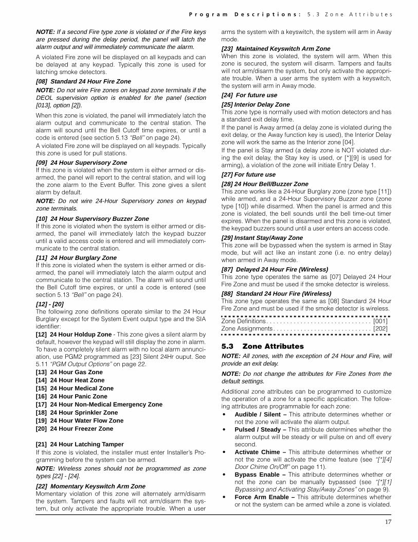
P r o g r a m D e s c r i p t i o n s : 5 . 3 Z o n e A t t r i b u t e s
17
NOTE: If a second Fire type zone is violated or if the Fire keysare pressed during the delay period, the panel will latch thealarm output and will immediately communicate the alarm.
A violated Fire zone will be displayed on all keypads and canbe delayed at any keypad. Typically this zone is used forlatching smoke detectors.
[08] Standard 24 Hour Fire ZoneNOTE: Do not wire Fire zones on keypad zone terminals if theDEOL supervision option is enabled for the panel (section[013], option [2]).
When this zone is violated, the panel will immediately latch thealarm output and communicate to the central station. Thealarm will sound until the Bell Cutoff time expires, or until acode is entered (see section 5.13 “Bell” on page 24).A violated Fire zone will be displayed on all keypads. Typicallythis zone is used for pull stations.
[09] 24 Hour Supervisory ZoneIf this zone is violated when the system is either armed or dis-armed, the panel will report to the central station, and will logthe zone alarm to the Event Buffer. This zone gives a silentalarm by default.NOTE: Do not wire 24-Hour Supervisory zones on keypadzone terminals.
[10] 24 Hour Supervisory Buzzer ZoneIf this zone is violated when the system is either armed or dis-armed, the panel will immediately latch the keypad buzzeruntil a valid access code is entered and will immediately com-municate to the central station.
[11] 24 Hour Burglary ZoneIf this zone is violated when the system is either armed or dis-armed, the panel will immediately latch the alarm output andcommunicate to the central station. The alarm will sound untilthe Bell Cutoff time expires, or until a code is entered (seesection 5.13 “Bell” on page 24).
[12] - [20] The following zone definitions operate similar to the 24 HourBurglary except for the System Event output type and the SIAidentifier:[12] 24 Hour Holdup Zone - This zone gives a silent alarm bydefault, however the keypad will still display the zone in alarm.To have a completely silent alarm with no local alarm annunci-ation, use PGM2 programmed as [23] Silent 24Hr ouput. See5.11 “PGM Output Options” on page 22.[13] 24 Hour Gas Zone [14] 24 Hour Heat Zone [15] 24 Hour Medical Zone [16] 24 Hour Panic Zone[17] 24 Hour Non-Medical Emergency Zone[18] 24 Hour Sprinkler Zone[19] 24 Hour Water Flow Zone[20] 24 Hour Freezer Zone
[21] 24 Hour Latching TamperIf this zone is violated, the installer must enter Installer’s Pro-gramming before the system can be armed.NOTE: Wireless zones should not be programmed as zonetypes [22] - [24].
[22] Momentary Keyswitch Arm ZoneMomentary violation of this zone will alternately arm/disarmthe system. Tampers and faults will not arm/disarm the sys-tem, but only activate the appropriate trouble. When a user
arms the system with a keyswitch, the system will arm in Awaymode.
[23] Maintained K eyswitch Arm ZoneWhen this zone is violated, the system will arm. When thiszone is secured, the system will disarm. Tampers and faultswill not arm/disarm the system, but only activate the appropri-ate trouble. When a user arms the system with a keyswitch,the system will arm in Away mode.
[24] For future use
[25] Interior Delay ZoneThis zone type is normally used with motion detectors and hasa standard exit delay time. If the panel is Away armed (a delay zone is violated during theexit delay, or the Away function key is used), the Interior Delayzone will work the same as the Interior zone [04].If the panel is Stay armed (a delay zone is NOT violated dur-ing the exit delay, the Stay key is used, or [*][9] is used forarming), a violation of the zone will initiate Entry Delay 1.
[27] For future use
[28] 24 Hour Bell/Buzzer ZoneThis zone works like a 24-Hour Burglary zone (zone type [11])while armed, and a 24-Hour Supervisory Buzzer zone (zonetype [10]) while disarmed. When the panel is armed and thiszone is violated, the bell sounds until the bell time-out timerexpires. When the panel is disarmed and this zone is violated,the keypad buzzers sound until a user enters an access code.
[29] Instant Stay/Away ZoneThis zone will be bypassed when the system is armed in Staymode, but will act like an instant zone (i.e. no entry delay)when armed in Away mode.
[87] Delayed 24 Hour Fire (Wireless)This zone type operates the same as [07] Delayed 24 HourFire Zone and must be used if the smoke detector is wireless.
[88] Standard 24 Hour Fire (Wireless)This zone type operates the same as [08] Standard 24 HourFire Zone and must be used if the smoke detector is wireless.
Zone Definitions. . . . . . . . . . . . . . . . . . . . . . . . . . . . . . . [001]Zone Assignments . . . . . . . . . . . . . . . . . . . . . . . . . . . . . [202]
5.3 Zone AttributesNOTE: All zones, with the exception of 24 Hour and Fire, willprovide an exit delay.
NOTE: Do not change the attributes for Fire Zones from thedefault settings.
Additional zone attributes can be programmed to customizethe operation of a zone for a specific application. The follow-ing attributes are programmable for each zone:• Audible / Silent – This attribute determines whether or
not the zone will activate the alarm output.• Pulsed / Steady – This attribute determines whether the
alarm output will be steady or will pulse on and off everysecond.
• Activate Chime – This attribute determines whether ornot the zone will activate the chime feature (see “[*][4]Door Chime On/Off” on page 11).
• Bypass Enable – This attribute determines whether ornot the zone can be manually bypassed (see “[*][1]Bypassing and Activating Stay/Away Zones” on page 9).
• Force Arm Enable – This attribute determines whetheror not the system can be armed while a zone is violated.
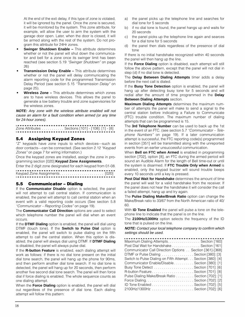
18
At the end of the exit delay, if this type of zone is violated,it will be ignored by the panel. Once the zone is secured,it will be monitored by the system. This zone attribute, forexample, will allow the user to arm the system with thegarage door open. Later, when the door is closed, it willbe armed along with the rest of the system. Do not pro-gram this attribute for 24Hr zones.
• Swinger Shutdown Enable – This attribute determineswhether or not the panel will shut down the communica-tor and bell for a zone once its swinger limit has beenreached (see section 5.19 “Swinger Shutdown” on page26)
• Transmission Delay Enable – This attribute determineswhether or not the panel will delay communicating thealarm reporting code for the programmed TransmissionDelay Period (see section 5.15 “Transmission Delay” onpage 25).
• Wireless Zone – This attribute determines which zonesare to have wireless devices. This allows the panel togenerate a low battery trouble and zone supervisories forthe wireless zones.
NOTE: Any zone with the wireless attribute enabled will notcause an alarm for a fault condition when armed (or any timefor 24-hour zones).
Zone Attributes . . . . . . . . . . . Sections [101] - [108]: [1] - [8]
5.4 Assigning Keypad Zones“Z” keypads have zone inputs to which devices—such asdoor contacts—can be connected. (See section 2.12 “KeypadZones” on page 7 for wiring information.)Once the keypad zones are installed, assign the zone in pro-gramming section [020] Keypad Zone Assignments .Enter the 2 digit zone designated for each keypad from 01-08.
Keypad Zone Assignments . . . . . . . . . . . . . . . . . . . . . . [020]
5.5 Communicator – DialingIf the Communicator Disable option is selected, the panelwill not attempt to call central station. If communication isenabled, the panel will attempt to call central station when anevent with a valid reporting code occurs (See section 5.8“Communicator – Reporting Codes” on page 19). The Communicator Call Direction options are used to selectwhich telephone number the panel will dial when an eventoccurs.If the DTMF Dialing option is enabled, the panel will dial usingDTMF (touch tone). If the Switch to Pulse Dial option isenabled, the panel will switch to pulse dialing on the fifthattempt to call the central station. When this option is dis-abled, the panel will always dial using DTMF. If DTMF Dialingis disabled, the panel will always pulse dial.If the R-button Feature is enabled, each dialing attempt willwork as follows: if there is no dial tone present on the initialdial tone search, the panel will hang up the phone for 90ms,and then perform another dial tone search. If no dial tone isdetected, the panel will hang up for 20 seconds, then performanother five second dial tone search. The panel will then forcedial if force dialing is enabled. The whole sequence counts asone dialing attempt.When the Force Dialing option is enabled, the panel will dialout regardless of the presence of dial tone. Each dialingattempt will follow this pattern:
a) the panel picks up the telephone line and searches fordial tone for 5 seconds
b) if no dial tone is found, the panel hangs up and waits for20 seconds
c) the panel picks up the telephone line again and searcesfor a dial tone for 5 seconds
d) the panel then dials regardless of the presence of dialtone
If there is no initial handshake recognized within 40 secondsthe panel will then hang up the line. If the Force Dialing option is disabled, each attempt will stillfollow the above pattern, except that the panel will not dial instep (d) if no dial tone is detected.The Delay Between Dialing Attempts timer adds a delaybefore the next call is dialed.If the Busy Tone Detection option is enabled, the panel willhang up after detecting busy tone for 5 seconds and willredial after the amount of time programmed in the DelayBetween Dialing Attempts section.Maximum Dialing Attempts determines the maximum num-ber of attempts the panel will make to send a signal to thecentral station before indicating a Failure to Communicate(FTC) trouble condition. The maximum number of dialingattempts that can be programmed is 15. The 3rd Telephone Number can be used to back up the 1stin the event of an FTC. (see section 5.7 “Communicator – Tele-phone Numbers” on page 19). If a later communicationattempt is successful, the FTC reporting code(s) programmedin section [351] will be transmitted along with the unreportedevents from an earlier unsuccessful communication.When Bell on FTC when Armed is enabled in programmingsection [702], option [8], an FTC during the armed period willsound an Audible Alarm for the length of Bell time-out or untilthe system is disarmed. If FTC Trouble Only when Armed isenabled, only the keypad buzzer will sound trouble beepsevery 10 seconds until a key is pressed.Post Dial Wait for Handshake determines the amount of timethe panel will wait for a valid handshake from the receiver. Ifthe panel does not hear the handshake it will consider the calla failed attempt, hang up and try again.The Pulse Dialing Make/Break Ratio option can change theMake/Break ratio to 33/67 from the North American ratio of 40/60. With ID Tone Enabled the panel will pulse a tone on the tele-phone line to indicate that the panel is on the line.The 2100Hz/1300Hz option selects the frequency of the IDtone that is pulsed on the line.NOTE: Contact your local telephone company to confirm whichsettings should be used.
Maximum Dialing Attempts. . . . . . . . . . . . . . . . Section [160]Post Dial Wait for Handshake . . . . . . . . . . . . . . Section [161]Communicator Call Direction Options . . Section [361]-[368]DTMF or Pulse Dialing . . . . . . . . . . . . . . . . Section [380]: [3] Switch to Pulse Dialing on Fifth Attempt . . . Section [380]: [4]Communicator Enable/Disable . . . . . . . . . . Section [380]: [1]Busy Tone Detect . . . . . . . . . . . . . . . . . . . . Section [701]: [6]R-button Feature . . . . . . . . . . . . . . . . . . . . . Section [701]: [8]Pulse Dialing Make/Break Ratio . . . . . . . . . Section [702]: [1]Force Dialing. . . . . . . . . . . . . . . . . . . . . . . . Section [702]: [2]ID Tone Enabled . . . . . . . . . . . . . . . . . . . . . Section [702]: [5]2100Hz/1300Hz . . . . . . . . . . . . . . . . . . . . . Section [702]: [6]

P r o g r a m D e s c r i p t i o n s : 5 . 6 C o m m u n i c a t o r – A c c o u n t N u m b e r s
19
Bell on FTC/Trouble Only . . . . . . . . . . . . . . Section [702]: [8]Delay Between Dialing Attempts . . . . . . . . . . . Section [703]
5.6 Communicator – Account NumbersThe account number is used by the central station to distin-guish between panels. There are two account numbers pro-grammable for the PC5008.NOTE: Six-digit account codes apply to the SIA and Pager for-mats only. All other formats only use the first four digits of theaccount code.
First Account Code (6 digits) . . . . . . . . . . . . . . Section [310]Second Account Code (6 digits) . . . . . . . . . . . Section [311]
5.7 Communicator – Telephone NumbersThe panel can use three different telephone numbers for com-municating with the central station. The First TelephoneNumber is the primary number, the Second Telephone Num-ber is the secondary number and the Third Telephone Num-ber will back up the First telephone number if enabled.NOTE: The Third Telephone Number will NOT back up theSecond Telephone Number.
NOTE: If you enter a telephone number section (sections [301]- [303]) at an LED keypad, pressing [#] will delete the pro-grammed telephone number and change all the digits to [F].
If the Alternate Dial option is enabled, the panel will alternatebetween the first and third telephone numbers when attempt-ing to call the central station. If the option is disabled, thepanel will only attempt to call the Third telephone number afterfailing to communicate with the first telephone number.NOTE: To use the Third Telephone Number, you must enable itin section [380], option [5], and program it in section [303].
Telephone numbers can be up to 32 digits. This allows you toadd special digits if required. To program the telephone number,enter the numbers 0 through 9 as required. The following is a listof programmable HEX digits and the functions they perform:HEX (B) - simulates the [*] key on a touch tone telephoneHEX (C) - simulates the [#] key on a touch tone telephoneHEX (D) - forces the panel to search for dial toneHEX (E) - forces the panel to pause for 2 secondsHEX (F) - marks the end of the telephone number
Two-way Voice MonitoringThe PC5928 module has built-in two-way voice for central sta-tion monitoring. The central station can select the audio sta-tion, listen/talk, extend on-line time and hang up. The Listen-In feature can be enabled separately for telephone numbers1/3 and 2.NOTE:The first digit of all telephone numbers must be the HEXdigit ‘D’ for dial tone search, or HEX digit ‘E’ for a two-secondpause.
First Telephone Number . . . . . . . . . . . . . . . . . . Section [301] Second Telephone Number . . . . . . . . . . . . . . . Section [302] Third Telephone Number . . . . . . . . . . . . . . . . . Section [303] Third Telephone Number Enable . . . . . . . . Section [380]: [5] Alternate Dial . . . . . . . . . . . . . . . . . . . . . . . Section [380]: [6]Telephone # 1 & 3 Listen-In Enable . . . . . . Section [381]: [5]Telephone # 2 Listen-In Enable . . . . . . . . . Section [381]: [6]
5.8 Communicator – Reporting CodesThe panel can be programmed to report events to the centralstation by sending the Reporting Code programmed for a par-ticular event.Reporting codes can be one or two digits and can use HEXdigits (A through F). For a complete description of reportingcodes which can be programmed and lists of automatic Con-tact ID and SIA format codes, please see Appendix A.NOTE:Do not use the digit C in a reporting code when using Pager Format. In most cases, the digit C will be interpreted asa [#] which will terminate the page before it has finished.
Reporting Codes . . . . . . . . . . . . . . . . . Section [320] to [353]
Cross Zone Police Reporting CodeThe Cross Zone Police Code Alarm will be sent when twodifferent alarms occur during any armed-to-armed period.When an alarm occurs while the panel is armed and a secondalarm occurs on a different zone during the same armedperiod, or after the system is disarmed, this code will be sent.All zone types contribute to this alarm. The cross zone policecode will be transmitted immediately unless either or bothzones have the Transmission Delay attribute enabled. If so,the code will be delayed for the programmed transmissiondelay time.
Cross Zone Police Code Alarm . . . . . . . . . . . . Section [328]
Zone RestoralsIf the Restoral on Bell Time-out option is selected, the panelwill send the Zone Restoral Reporting Code for the zone ifthe bell cut-off time has expired and the zone is secured. If thezone is not secured when the bell cut-off time expires, thepanel will send the restoral immediately once the zone issecured, or when the system is disarmed. If the Restoral onBell Time-out option is not selected, the panel will immediatelysend the Zone Restoral Reporting Code when the zone issecured, regardless of whether or not the alarm output isactive.NOTE:24 Hour type zones will report the restoral immediately when the zone is secured.
Restoral on Bell Time-out. . . . . . . . . . . . . . .Section [380]: [2]
Closings (Arming Codes)If the Closing Confirmation option is enabled, once the exitdelay expires, the keypad will sound a series of eight beeps toconfirm to the user that the closing code was sent andreceived by the central station.
Closing Confirmation . . . . . . . . . . . . . . . . . .Section [381]: [4]
Openings/Closings by Wireless KeyIf you are using a PC5132 v3.0 or higher, wireless keys withaccess codes may be identified when they are used to arm ordisarm the system: the panel will log and transmit opening orclosing by access code (the same as if an access code hadbeen used to arm/disarm the system). If wireless keys with noaccess code are used, the event will be logged and transmit-ted as special closing or opening by keyswitch. The Function Keys Require Code option must be selected(section [015], option 4 OFF) in order for wireless keys to beidentified for arming. Disarming will always be logged byaccess code, if one is programmed for the Key, regardless ofthis option.

20
Wireless MaintenanceThe panel will transmit a Wireless Device Low Battery Alarmreporting code if a low battery condition is indicated by adetector. Transmission and logging to the event buffer of thetrouble will be delayed by the number of days programmedfor Zone Low Battery Transmission Delay . The WirelessDevice Low Battery Restoral reporting code will be transmit-ted when the problem is corrected. The specific zone thatcaused the trouble will be recorded in the event buffer.NOTE: The restoral will not be transmitted until all detectors indicate good battery conditions.
Wireless Maintenance Reporting Codes. . . . . . Section [353]Zone Low Battery Transmission Delay . . . . . . . Section [370]
AC Failure Trouble Alarm CodeTo prevent the panel from transmitting an AC Failure TroubleAlarm reporting code during short power outages, the panelwill not send the signal unless AC power is lost for the amountof minutes programmed for the AC Failure CommunicationDelay. The AC Failure Trouble Restora l reporting code fol-lows the AC failure communication delay as well.NOTE:If AC Failure Communications Delay is programmed as “000,” then the AC failure transmission will be immediate.
NOTE: For proper communication of PC5204 AC troubles, pro-gram the AC Failure Communication Delay as “000”.
AC Failure Communication Delay . . . . . . . . . . . Section [370]
5.9 Communicator – Reporting FormatsEach communication telephone number can be programmedto report using any one of ten formats available. Two 20 BPSpulse formats and two 10 BPS formats are supported, in addi-tion to Contact ID, SIA, Pager and Residential Dial formats. The Communicator Call Direction options can be used todisable the reporting of events such as Openings and Clos-ings. NOTE:Do not program the 2nd telephone number to use Con-tact ID or SIA reporting code formats (section [360]) if Auto-matic reporting codes are selected for either Contact ID or SIA(section [381]).
Communicator Format Options . . . . . . . . . . . . . Section [360]Communicator Call Directions. . . . . . . Section [361] to [368]
The following is a description of each reporting format:
Pulse FormatsDepending on which pulse format is selected, the panel willcommunicate using the following specifications:• 3/1, 3/2, 4/1 or 4/2• 1400 or 2300 Hz handshake• 10 or 20 bits per second• non-extendedWith the 1600Hz Handshake option enabled, the communica-tor will respond to 1600Hz handshakes when using the report-ing Communication Formats 01 and 02 only. When theStandard Handshake option is enabled, the communicator willrespond to the handshake specified by the BPS format(1400Hz or 2300Hz).
Additional Notes on Pulse Formats1. The digit ‘0’ will send no pulses and is used as a filler digit.
2. When programming account numbers, enter four digits.When programming a three digit account number, thefourth digit must be programmed as ‘0’.
• 3 digit account number [123] - program [1230] 3. If an account number has a ‘0’ in it, substitute a HEX digit
‘A’ for the ‘0’. For example:• 3 digit account number [502] - program [5A20] • 4 digit account number [4079] - program [4A79]
4. Reporting codes are two digits. When programming sin-gle-digit Reporting Codes, the second digit must be pro-grammed as a ‘0’. If a ‘0’ is to be transmitted, substituteHEX digit ‘A’. For example:• 1 digit Reporting Code [3] - program [30] • 2 digit Reporting Code [30] - program [3A]
5. To prevent the panel from reporting an event, the reportingcode should be programmed as [00] or [FF].
1600Hz/Standard Handshake. . . . . . . . . . . Section [702]: [4]
Contact IDContact ID is a specialized format that will communicate infor-mation using tones rather than pulses. This format allows moreinformation to be sent faster than other formats. For example,in addition to reporting an alarm in zone one, the Contact IDformat will also report the type of alarm, such as an Entry/Exitalarm.If the Contact ID uses Programmed Reporting Codesoption is enabled, a two digit number from Appendix A mustbe entered in programming sections [320] to [353] for eachevent to be transmitted. The two digit number determines thetype of alarm. The panel will automatically generate all otherinformation, including the zone number.If the Contact ID uses Automatic Reporting Codes option isenabled, the panel will operate as follows:1. If an event’s reporting code is programmed as [00], the
panel will not attempt to call the central station.2. If the reporting code for an event is programmed as any-
thing from [01] to [FF], the panel will automatically gener-ate the zone or access code number. See Appendix A for alist of the codes which will be transmitted.
NOTE:If the Automatic Contact ID option is selected, the panel will automatically generate all zone and access code numbers,eliminating the need to program these items.
If the Contact ID uses Programmed Reporting Codesoption is enabled, the panel will operate as follows:1. If an event’s reporting code is programmed as [00] or [FF],
the panel will not attempt to call central station.2. If the reporting code for an event is programmed as any-
thing from [01] to [FE], the panel will send the programmedreporting code.
Additional Notes on Contact ID1. Account numbers must be four digits.2. All reporting codes must be two digits.3. Substitute the HEX digit ‘A’ for the ‘0’.4. To prevent the panel from reporting an event, the reporting
code should be programmed as [00].Please refer to Appendix A for a list of Contact ID Identifiers.
Contact ID Uses Programmed/Automatic Codes. . .[381]: [7]
SIASIA is a specialized format that will communicate informationquickly using Frequency Shift Keying (FSK) rather thanpulses. The SIA format will automatically generate the type of

P r o g r a m D e s c r i p t i o n s : 5 . 1 0 D o w n l o a d i n g
21
signal being transmitted, such as Burglary, Fire, Panic etc.The two digit reporting code is used to identify the zone oraccess code number.NOTE: If the Automatic SIA option is selected, the panel will automatically generate all zone and access code numbers,eliminating the need to program these items.
If the SIA Sends Automatic Reporting Codes option isenabled, the panel will operate as follows:1. If an event’s reporting code is programmed as [00], the
panel will not attempt to call the central station.2. If the reporting code for an event is programmed as any-
thing from [01] to [FF], the panel will automatically gener-ate the zone or access code number and send thereporting code.
If the SIA Sends Programmed Reporting Codes option isenabled, the panel will operate as follows:1. If an event’s reporting code is programmed as [00] or [FF],
the panel will not attempt to call central station.2. If the reporting code for an event is programmed as any-
thing from [01] to [FE], the panel will send the programmedreporting code.
Please refer to Appendix A for a list of SIA identifiers.
SIA Sends Automatic Reporting Codes . . . Section [381]: [3]
Pager FormatThe communication format option for either telephone numbercan be programmed as Pager format. If an event occurs andthe Communicator Call Direction options direct the call to atelephone number with the Pager Format selected, the panelwill attempt to page.When calling a pager, extra digits will be required in order forthe format to function properly. The following is a list of Hexdigits and the functions they perform:Hex [B] - simulates the [*] key on a touch tone telephoneHex [C] - simulates the [#] key on a touch tone telephoneHex [D] - forces the panel to search for dial toneHex [E] - two second pauseHex [F] - marks the end of the telephone numberThe panel will attempt to call the pager once. Once the appro-priate telephone number is dialed, the panel will send theaccount number and Reporting Code followed by the [#] key(Hex [C]).The panel has no way of confirming if the pager was calledsuccessfully. A Failure To Communicate trouble will only begenerated if the panel detects a busy tone on all dialingattempts, or if no dial tone is detected on all dialing attempts.The pager format will not cause any form of ringback.NOTE:Do not use the digit C in a reporting code when using Pager Format. In most cases, the digit C will be interpreted asa [#] which will terminate the page before it has finished.
NOTE:If the panel detects a busy signal, it will attempt to page again. It will make the maximum number of attempts pro-grammed in section [160].
NOTE:Force dialing should be disabled when using Pager format.
NOTE:When using Pager format, you must program two hex digit E’s at the end of the telephone number
NOTE:The Pager Format cannot be used with the GSM1000 cellular communicator.
Residential Dial FormatThe Residential Dial format allows the communication ofevents directly to a user over a telephone line. When an eventoccurs that the panel is programmed to communicate, thepanel seizes the line and dials the programmed telephone
number(s). The panel then emits a double beep on the lineevery 3 seconds. This indicates to the user receiving the callthat the control panel is calling.The user must acknowledge the call by pressing 1, 2, 4, 5, 7,8, 0, * or # from any touchtone telephone. The panel will waitfor this acknowledgment for the duration of Post Dial Wait forHandshake timer. Once the panel receives the handshake, it will emit an alarmtone over the telephone line for 20 seconds. If several alarmsoccur at the same time, only one call will be made to eachtelephone number the panel is programmed to call.NOTE: The keys 3, 6 and 9 are not valid handshakes.
NOTE: If the panel fails to communicate in Residential Dialmode, the FTC trouble will not latch.
Post Dial Wait for Handshake Timer . . . . . . . . . Section [161]
5.10 DownloadingThe required downloading software is DLS-1 version 6.3Sand up.Downloading allows you to program the entire control panelvia a computer, a modem and a telephone line. All functions,features, their changes and status – such as trouble condi-tions and open zones – can be viewed or programmedthrough downloading.NOTE:Downloading is always enabled for six hours each time the panel is powered up, unless the User Can Enable DLSWindow option is disabled
The panel will answer calls for downloading when the pro-grammed Number of Rings is heard by the panel. If the Answering Machine/Double Call option is enabled (orduring the first six hours after power up), the panel will answerincoming calls for downloading in the following manner:1. The panel hears one or two rings then misses a ring.2. At this point the panel will start the double-call timer.3. If the panel hears another ring before the Answering
Machine Double-Call Timer expires, it will answer on thefirst ring of the second call.
The panel will immediately go on line and begin downloading.If the Call-Back option is enabled, the panel and the com-puter will both hang up. The panel will then call the Down-loading Computer’s Telephone Number and wait for thecomputer to answer. Once the computer answers, download-ing will begin.If the User Enabled DLS Window option is ON, the user canactivate the downloading feature for a set period of time byentering [*][6][Master Code][5]. If the Full 6-hour User Enabled DLS Window option isenabled, when the user opens the DLS window with[*][6][Master code][5], the DLS window will remain open forsix hours. The DLS window will remain open after a successfulhang-up from a downloading call. If the One Time 1-hourUser Enabled DLS Window option is enabled, when the useropens the DLS window with [*][6][Master code][5], the DLSwindow will stay open for one hour, and will close after a suc-cessful hang-up from a downloading call.After six hours, the panel will not answer incoming calls unlessthe Answering Machine/Double Call option is enabled, or theNumber of Rings is programmed to be more than [0].If the User Initiated Call-Up option is enabled, the user canhave the panel initiate a call to the downloading computer bypressing [*][6][Master Code][6].

22
The Download Access Code and Panel Identifier Code arefor security and proper identification. Both the panel and thecomputer file should contain the same information pro-grammed before attempting to download.The time to complete a successful download can be significantlyreduced with the use of the PC-LINK. This adaptor makes it pos-sible to perform on-site downloading. To Initiate Local Down-loading via the PC-LINK , enter [*][8][Installer’sCode][499][Installer’s Code][499]. All keypads will be busy forthe duration of the PC-LINK connection. The status LEDs will dis-play the current system status on the keypad where the PC-LINKwas initiated. For more information on connecting the PC-LINK,refer to your “PC-LINK Download Kit Instruction Sheet”. NOTE: When a zone status upload is performed throughPC-LINK, the information uploaded may not be accurate. Formore information, refer to your DLS-1 manual.
NOTE:When uploading labels from LCD keypads, only labels from the LCD keypad assigned to slot 8 will be uploaded.
Answering Machine/Double Call . . . . . . . .Section [401]: [1]User Enable DLS Window . . . . . . . . . . . . .Section [401]: [2]Call-Back . . . . . . . . . . . . . . . . . . . . . . . . . . .Section [401]: [3]User-initiated Call-up enabled/disabled . . .Section [401]: [4]One/Six Hour User-enabled DLS Window. .Section [702]: [7]Downloading Computer’s Telephone Number . Section [402] Downloading Access Code. . . . . . . . . . . . . . . . Section [403] Panel Identification Code . . . . . . . . . . . . . . . . . Section [404] Answering Machine Double Call Timer . . . . . . Section [405] Number of Rings to Answer On. . . . . . . . . . . . . Section [406]Initiate Local Downloading (PC-LINK). . . . . . . . Section [499]
5.11 PGM Output OptionsProgrammable outputs can be programmed by selecting oneof the output options listed below (exceptions noted).
Main Board PGM Outputs . . . . . . . . . . . . . . . . . Section [009]PC5208 PGM Outputs . . . . . . . . . . . . . . . . . . . . Section [010]PC5204 PGM Outputs . . . . . . . . . . . . . . . . . . . . Section [011]
NOTE:PGM outputs cannot be disabled in installer’s program-ming. To disable a PGM output, you must remove all wiringfrom the output.
[01] Burglary and Fire Bell OutputThe output will activate when the alarm output is active andwill deactivate when the alarm output is silenced. If the alarmoutput is pulsing, the PGM output will pulse as well. This out-put will follow the activation of the alarm output (pre-alert) fordelayed fire zones.
[02] For future use
[03] Sensor Reset ([*][7][2])NOTE:This output will normally be active (switched to ground).
This option is used to reset power for latching smoke detec-tors. The output will deactivate for five seconds when the[*][7][2] command is entered (see “[*][7] Command OutputFunctions” on page 12). The keypad buzzer will not sound forthe five second period. After performing a sensor reset, wait15 seconds before attempting to arm the system.Please refer to the Control Panel Wiring Diagram in this man-ual for wiring instructions.NOTE:Only ONE of options [03] Sensor Reset and [20] Com-mand Output Option #2 may be programmed on the same sys-tem.
[04] For future use
[05] Armed StatusWhen the system is armed, the PGM output will activate at thebeginning of the exit delay. The output deactivates when thesystem is disarmed.
[06] Ready To Arm The PGM will be active as long as the system is ready to armand all non-force armable zones on the system are restored.Once an access code is entered to arm the system and theexit delay begins, the PGM output is deactivated.
[07] Keypad Buzzer Follower ModeThe PGM will activate when any of the following events occurand will remain active for as long as the keypad buzzer isactive:• Door Chime • Entry Delay • Auto-Arm Prealert • Audible Exit Delay • 24 Hour Supervisory Buzzer Zone
[08] Courtesy PulseUpon arming, the PGM output will activate for the duration ofthe exit delay plus an additional two minutes. Upon disarming,the PGM output will activate for the duration of the entry delayplus an additional two minutes.
[09] System Trouble OutputThe PGM output will activate when any of the selected troubleconditions are present. It will deactivate when all the selectedtrouble conditions are cleared.The PGM attributes for this option, programmed in sections[141] to [154], differ from the standard selection of attributes.Program which trouble conditions will activate the output byselecting some or all of the following attributes:Attribute
[1].......... Service Required (battery, bell, general trouble,general tamper, general supervisory)
[2].......... AC Failure[3].......... Telephone Line Trouble[4].......... Failure to Communicate[5].......... Fire Trouble / Zone Fault[6].......... Zone Tamper[7].......... Zone Low Battery[8].......... Loss of Clock
[10] System Event (Strobe Output)The output activates when any of the selected system events(alarms) occur on the system. NOTE:This output will activate for silent and audible alarms or medical conditions only. It will not activate during pre-alert ordelays.
If attribute [8] is turned ON, the output will activate for thenumber of seconds programmed in the PGM output timer(section [164]).If attribute [8] is turned OFF, in the armed state, the output willdeactivate only once the system is disarmed. If an alarm acti-vates this output in the disarmed state, the output will deacti-vate if a user enters a valid access code while the Bell Cut-offtimer is counting down. The output will also deactivate ifsomeone arms the system after the Bell Cut-off has expired. This output can be used to indicate that an alarm hasoccurred before entering the premises.The PGM attributes for this option, programmed in Sections[141] to [154], differ from the standard selection of attributes.Program which events will activate the output by selectingsome or all of the following attributes:

P r o g r a m D e s c r i p t i o n s : 5 . 1 1 P G M O u t p u t O p t i o n s
23
Attribute[1]......... Burglary (Delay, Instant, Interior, Stay/Away and
24 Hour Burglary Zones)[2]......... Fire (Fire Keys, Fire Zones) [3]......... Panic (Panic Keys and Panic Zones)[4]......... Medical (Auxiliary Keys, Medical and Emergency
Zones)[5]......... Supervisory (Supervisory, Freezer and Water
Zones)[6]......... Priority (Gas, Heat, Sprinkler and 24 Hour Latch-
ing Zones)[7]......... Holdup (Holdup zones)[8]......... Output Follows Timer (output will activate for the
number of seconds programmed in the PGM Out-put Timer) / Output Latched
NOTE:If attribute [8] is turned ON, attributes [1-7] must also be turned ON.
PGM Output Timer . . . . . . . . . . . . . . . . . . . . . . Section [164]
[11] System Tamper (All Sources)The PGM output will activate when any tamper condition ispresent and will deactivate when all tampers are restored.
[12] TLM and AlarmThe PGM output activates when the system experiences botha telephone line trouble and an alarm. When the system isarmed, the output will deactivate only if an access code isentered or if the telephone line is restored. If an alarm activates this output in the disarmed state, the out-put will deactivate if a user enters a valid access code whilethe Bell Cut-off timer is counting down, or if the telephone lineis restored. The output will also deactivate if someone armsthe system after the Bell Cut-off has expired.NOTE:This output will activate for all silent and audible alarms except the Duress alarm and 24-hr PGM inputs.
[13] Kissoff OutputThe output will activate for two seconds after the control panelreceives the kissoff transmission from the central station.
[14] Ground Start PulseThe PGM Output will activate for two seconds to obtain a dialtone on Ground Start telephone equipment before the panelattempts to dial. Insert two 2-second pauses at the beginningof the telephone number when using this option.
[15] Remote Operation (DLS-1 Support)This output can be activated and deactivated remotely usingthe DLS software.
[16] GSM1000 Support (PGM1 Only)The PGM output will be used as a data wire to communicatetelephone number information for the GSM1000 cellular unit.
[17] Away Armed StatusWhen the system is armed in the Away mode, the PGM outputwill activate at the beginning of the exit delay. The outputdeactivates when the panel is disarmed.
[18] Stay Armed StatusWhen the system is armed in the Stay mode, the PGM outputwill activate at the beginning of the exit delay. The outputdeactivates when the panel is disarmed.
[19] [*][7][1] Command Output Option #1
[20] [*][7][2] Command Output Option #2
[21] [*][7][1] Command Output Option #3
[22] [*][7][2] Command Output Option #4These outputs are user-initiated by entering [*][7][1-4] at anykeypad. When any output is activated, three acknowledgmentbeeps are sounded.
NOTES on Option [20] [*][7][2]:Press [*][7][2][Access Code, if required] to activate any out-put programmed as one of PGM output option [03] or [20].Traditionally, [*][7][2] has been reserved for resetting smokedetectors. Smoke detectors should now be programmed asoutput [03] “Sensor Reset”. NOTE:Only ONE of options [03] Sensor Reset and [20][*][7][2] Command Output Option #2 may be programmed on the samesystem.
[23] Silent 24 Hour (PGM2 Only)A Panic button may be connected to the PGM2 terminal foruse as a silent 24 hour Panic. The keypad will not indicate thealarm in any way and the Bell will remain silent but the PGM2Alarm reporting code will be sent to the central station. PGMoutput option [23] will not activate other programmable out-puts of any kind. This input does not follow Swinger Shutdown.
[24] Audible 24 Hour (PGM2 Only)A Panic button may be placed on the PGM2 Terminal for useas an Audible 24 Hour Panic. When the button is pressed,LCD keypads will indicate “System in Alarm”, the bell willsound until the Bell Cut-off expires or until a valid access codeis entered, and the PGM2 Alarm reporting code will be sent tothe central station. PGM output option [24] will not activateother programmable outputs except for outputs programmedas [01]. This input does not follow Swinger Shutdown.
[26] Battery Test (PGM1 only)When the panel performs the 10-second battery check, theBattery Test output will activate. You may use this output typeto switch a 20 ohm load across to test the battery for the 10second battery check period. Connect a resistor between theBell+ and PGM1 terminals.
[27] Police CodeWhen a Police Code event occurs, this output will activateuntil the panel is disarmed or an access code is entered. (See“Cross Zone Police Reporting Code” on page 19.)
[28] HoldupWhen a Holdup zone (zone type [12]) goes into alarm, thisoutput will activate until the panel is disarmed or an accesscode is entered. A tamper or fault on a Holdup zone will notcause Holdup outputs to activate.
[29] Zone FollowerOutputs programmed this way will be active when pro-grammed zones are violated. The Output Attributes determinewhich zones the output will follow. The output will not activatefor zone types (22) or (23) if DEOL is enabled.Example: PGM 1 is programmed as a zone follower withattributes 1, 6, and 8 on. PGM1 will activate when any ofzones 1, 6, or 8 are violated. PGM1 will deactivate when allthree zones are restored.NOTE: Zone follower outputs cannot be inverted.
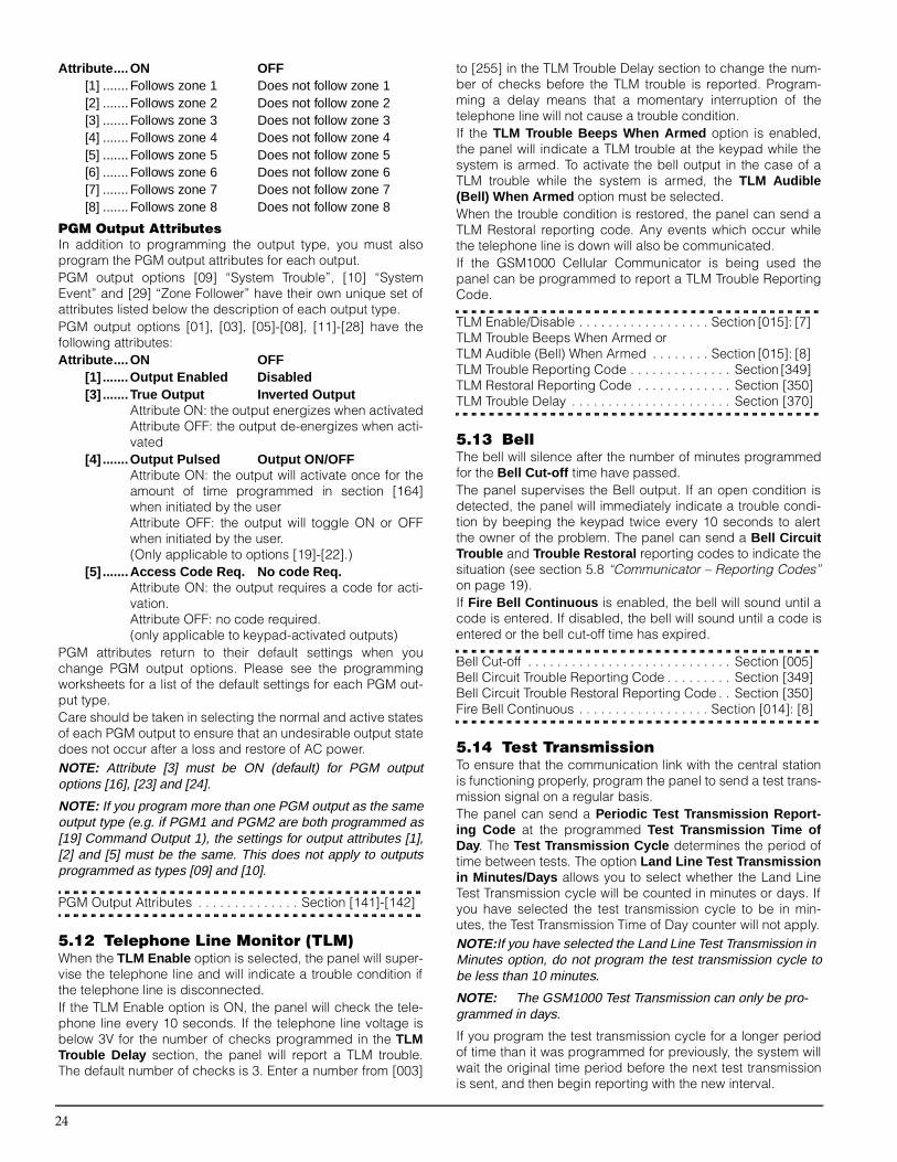
24
Attribute ....ON OFF[1] .......Follows zone 1 Does not follow zone 1[2] .......Follows zone 2 Does not follow zone 2[3] .......Follows zone 3 Does not follow zone 3[4] .......Follows zone 4 Does not follow zone 4[5] .......Follows zone 5 Does not follow zone 5[6] .......Follows zone 6 Does not follow zone 6[7] .......Follows zone 7 Does not follow zone 7[8] .......Follows zone 8 Does not follow zone 8
PGM Output AttributesIn addition to programming the output type, you must alsoprogram the PGM output attributes for each output. PGM output options [09] “System Trouble”, [10] “SystemEvent” and [29] “Zone Follower” have their own unique set ofattributes listed below the description of each output type.PGM output options [01], [03], [05]-[08], [11]-[28] have thefollowing attributes:Attribute ....ON OFF
[1] .......Output Enabled Disabled[3] .......True Output Inverted Output
Attribute ON: the output energizes when activatedAttribute OFF: the output de-energizes when acti-vated
[4] .......Output Pulsed Output ON/OFFAttribute ON: the output will activate once for theamount of time programmed in section [164]when initiated by the userAttribute OFF: the output will toggle ON or OFFwhen initiated by the user. (Only applicable to options [19]-[22].)
[5] .......Access Code Req. No code Req.Attribute ON: the output requires a code for acti-vation.Attribute OFF: no code required.(only applicable to keypad-activated outputs)
PGM attributes return to their default settings when youchange PGM output options. Please see the programmingworksheets for a list of the default settings for each PGM out-put type.Care should be taken in selecting the normal and active statesof each PGM output to ensure that an undesirable output statedoes not occur after a loss and restore of AC power.NOTE: Attribute [3] must be ON (default) for PGM outputoptions [16], [23] and [24].
NOTE: If you program more than one PGM output as the sameoutput type (e.g. if PGM1 and PGM2 are both programmed as[19] Command Output 1), the settings for output attributes [1],[2] and [5] must be the same. This does not apply to outputsprogrammed as types [09] and [10].
PGM Output Attributes . . . . . . . . . . . . . . Section [141]-[142]
5.12 Telephone Line Monitor (TLM)When the TLM Enable option is selected, the panel will super-vise the telephone line and will indicate a trouble condition ifthe telephone line is disconnected. If the TLM Enable option is ON, the panel will check the tele-phone line every 10 seconds. If the telephone line voltage isbelow 3V for the number of checks programmed in the TLMTrouble Delay section, the panel will report a TLM trouble.The default number of checks is 3. Enter a number from [003]
to [255] in the TLM Trouble Delay section to change the num-ber of checks before the TLM trouble is reported. Program-ming a delay means that a momentary interruption of thetelephone line will not cause a trouble condition.If the TLM Trouble Beeps When Armed option is enabled,the panel will indicate a TLM trouble at the keypad while thesystem is armed. To activate the bell output in the case of aTLM trouble while the system is armed, the TLM Audible(Bell) When Armed option must be selected.When the trouble condition is restored, the panel can send aTLM Restoral reporting code. Any events which occur whilethe telephone line is down will also be communicated.If the GSM1000 Cellular Communicator is being used thepanel can be programmed to report a TLM Trouble ReportingCode.
TLM Enable/Disable . . . . . . . . . . . . . . . . . . Section [015]: [7] TLM Trouble Beeps When Armed or TLM Audible (Bell) When Armed . . . . . . . . Section [015]: [8] TLM Trouble Reporting Code . . . . . . . . . . . . . . Section [349] TLM Restoral Reporting Code . . . . . . . . . . . . . Section [350]TLM Trouble Delay . . . . . . . . . . . . . . . . . . . . . . Section [370]
5.13 BellThe bell will silence after the number of minutes programmedfor the Bell Cut-off time have passed. The panel supervises the Bell output. If an open condition isdetected, the panel will immediately indicate a trouble condi-tion by beeping the keypad twice every 10 seconds to alertthe owner of the problem. The panel can send a Bell CircuitTrouble and Trouble Restoral reporting codes to indicate thesituation (see section 5.8 “Communicator – Reporting Codes”on page 19).If Fire Bell Continuous is enabled, the bell will sound until acode is entered. If disabled, the bell will sound until a code isentered or the bell cut-off time has expired.
Bell Cut-off . . . . . . . . . . . . . . . . . . . . . . . . . . . . Section [005]Bell Circuit Trouble Reporting Code . . . . . . . . . Section [349]Bell Circuit Trouble Restoral Reporting Code . . Section [350]Fire Bell Continuous . . . . . . . . . . . . . . . . . . Section [014]: [8]
5.14 Test TransmissionTo ensure that the communication link with the central stationis functioning properly, program the panel to send a test trans-mission signal on a regular basis.The panel can send a Periodic Test Transmission Report-ing Code at the programmed Test Transmission Time ofDay. The Test Transmission Cycle determines the period oftime between tests. The option Land Line Test Transmissionin Minutes/Days allows you to select whether the Land LineTest Transmission cycle will be counted in minutes or days. Ifyou have selected the test transmission cycle to be in min-utes, the Test Transmission Time of Day counter will not apply.NOTE:If you have selected the Land Line Test Transmission in Minutes option, do not program the test transmission cycle tobe less than 10 minutes.
NOTE: The GSM1000 Test Transmission can only be pro-grammed in days.
If you program the test transmission cycle for a longer periodof time than it was programmed for previously, the system willwait the original time period before the next test transmissionis sent, and then begin reporting with the new interval.

P r o g r a m D e s c r i p t i o n s : 5 . 1 5 T r a n s m i s s i o n D e l a y
25
The panel can also send a test for the GSM1000 Cellular Com-municator, if used. If the GSM1000 Test Transmission Code isprogrammed, the panel will send a cellular test at the intervalprogrammed in the GSM1000 Test Transmission Cycle.Users can also generate a communicator test. If the SystemTest Reporting Code is programmed, the panel will send thesignal when the System Test keypad command is entered(see “[*][6] User Functions” on page 11).
Test Transmission Reporting Codes. . . . . . . . . Section [352] Test Transmission Time of Day . . . . . . . . . . . . . Section [371] Test Transmission Cycles . . . . . . . . . . . . . . . . . Section [370] Land Line Test Transmission M/D. . . . . . . . Section [702]: [3]
5.15 Transmission DelayIf the transmission delay zone attribute is selected for a givenzone, the panel will delay reporting an alarm for that zone forthe number of seconds programmed for the TransmissionDelay Time . If the panel is disarmed before the delay timeexpires, the panel will not report the event.
Transmission Delay Time . . . . . . . . . . . . . . . . . Section [370]
5.16 Fire, Auxiliary and Panic Keys The emergency keys are available on all keypads. These keysmust be pressed and held for two seconds before they willactivate. This two second delay is designed to help preventaccidental activation.
If the [F] / Key option is enabled, when the Fire keys arepressed and held for two seconds, the panel will activate thealarm output. The alarm output will sound until a code isentered or until the bell cut-off time expires. Communication ofthe signal to central station is immediate.
If the [A] / Key is pressed and held for two seconds, thepanel will sound the keypad beeps three times to verify activa-tion. The panel will beep the keypad ten times rapidly when akissoff is received, to verify communication to the central sta-tion.
If the [P] / Key is pressed and held for two seconds, thepanel will immediately communicate the signal to central sta-tion. If [P] Key Audible Bell and Buzzer option is enabled, when auser presses the [P] / key, the keypad will beep three timesand the panel will activate the alarm output until an accesscode is entered or the bell cut-off expires. If the option is dis-abled, the Panic alarm will be completely silent.Each LCD keypad may be programmed to have the [F], [A], &[P] keys enabled or disabled. Please refer to Appendix B:“Programming LCD Keypads” on page 45.NOTE:The Fire, Auxiliary, Panic keys will operate even if Key-pad Blanking is active (See section 5.22 “Keypad Blanking” onpage 26).
[F] Key Enable . . . . . . . . . . . . . . . . . . . . . . Section [015]: [1][P] Key Audible Bell and Buzzer . . . . . . . . Section [015]: [2]
5.17 Arming/Disarming OptionsIf the Quick Arm option is enabled, the panel can be armedwithout an access code by entering [*][0] or by pressing theStay or Away function key.The Quick Exit option, if enabled, will allow someone to leavean armed premises through a Delay type zone without having
to disarm and re-arm the system. See “[*][0] Quick Exit” onpage 12.If the Arm/Disarm Bell Squawk option is enabled, the panelwill squawk the alarm output once upon arming and twiceupon disarming. If an alarm is in memory, when the panel isdisarmed the bell will sound three pairs of disarm squawks. The Opening After Alarm Keypad Ringback option willcause the keypad to beep 8 times rapidly after the OpeningAfter Alarm reporting code has been successfully transmittedto the central station. The Opening After Alarm Bell Ring-back option will cause the panel to squawk the bell 8 timesrapidly after the Opening After Alarm reporting code has beensuccessfully transmitted to the central station.NOTE:If the panel is armed using the Stay function key, or by entering [*][9][access code], there will be no bell squawks dur-ing entry and exit delays, except for the arm/disarm bellsquawks.
Closing Confirmation , if enabled, will cause the keypad tobeep 8 times rapidly after the closing reporting code hasbeen successfully transmitted to central station.If the Bypass Status Displayed While Armed option is cho-sen, the Bypass light will be ON while the system is armed toindicate that there are bypassed zones.If the AC/DC Inhibit Arming option is enabled, the panel willnot arm if there is an AC or DC (battery) trouble present on thesystem. Arming will not be allowed until the AC or battery trou-ble is cleared. If no AC or battery trouble is currently present,when a user attempts to arm the system, the panel will do anautomatic battery test of the main panel and modules thatsupport a backup battery. If the battery is good, the systemwill arm. If the battery is bad, the system will not arm.If the AC/DC Inhibit Arming option is disabled, the panel willnot do an automatic battery test when arming is attemptedand the user will not be prevented from arming the systemwhen there is an AC or battery trouble.If you enable the Unidentified Wireless Key Disarmingoption, the disarm button will work on wireless keys whichhave not been assigned access codes. Wireless keys canonly be assigned access codes when used with PC5132 v3.0or higher. To prevent disarming by wireless keys which don’t haveaccess codes, disable this option. (Please see your PC5132manual for more information on programming wireless keys.)NOTE:This option must be enabled when using a PC5132 v2.1 or earlier.
Quick Arm Enable . . . . . . . . . . . . . . . . . . . .Section [015]: [4] Quick Exit Enable. . . . . . . . . . . . . . . . . . . . .Section [015]: [3]Arm/Disarm Bell Squawk . . . . . . . . . . . . . . .Section [014]: [1]Closing Confirmation . . . . . . . . . . . . . . . . . .Section [381]: [4]Opening After Alarm Keypad Ringback . . .Section [381]: [1]Opening After Alarm Bell Ringback. . . . . . .Section [381]: [2]Bypass Status Displayed While Armed . . . .Section [016]: [7]AC/DC Inhibit Arming . . . . . . . . . . . . . . . . .Section [701]: [3]Unident. Wkey Disarm Enabled. . . . . . . . . .Section [017]: [1]
5.18 Entry/Exit Delay OptionsTwo different Entry Delays can be programmed: the first entrydelay will be enabled for Delay 1 type zones and the secondfor Delay 2 type zones. Only one Exit Delay can be pro-grammed.

26
NOTE:When the panel is armed, the entry delay will follow the entry delay time programmed for the delay zone which is vio-lated first.
Upon arming, the panel will begin the exit delay. If the AudibleExit Delay with Urgency option is enabled, the keypad willbeep at one second intervals until the exit delay expires. Thekeypad will beep rapidly for the last 10 seconds of exit delayto warn the user that the system is about to arm. If this optionis disabled, the keypad will not beep during the exit delay.The Audible Exit Fault , as explained in section 3.1 “Armingand Disarming” on page 9, will notify the user if they failed tosecure the premises upon arming. This option can be enabledor disabled according to the user’s needs.For commercial applications, the Bell Squawk on Exit Delayoption may be enabled. The panel will squawk the alarm out-put once every second when the exit delay is initiated andthree times per second for the last 10 seconds until the exitdelay expires.NOTE:The bell will not squawk when the panel is Stay or No-entry armed.
Upon entry, if a Delay type zone is violated, the panel willbegin the entry delay. The keypad will emit a steady tone. Thekeypad will pulse the keypad sounder during the last 10 sec-onds to warn the user the system is about to go into alarm. Ifthere was an alarm during the armed period, the keypad willpulse for the entire entry delay to warn the user of the previousalarm.For commercial applications Bell Squawk on Entry Delaymay be enabled. The panel will squawk the alarm output onceevery second until the entry delay expires or the system is dis-armed. If the Bell Squawk During Auto Arm option is enabled, thebell will squawk once every 10 seconds for one minute duringthe Auto-arm pre-alert. This will notify anyone on the premisesthat the system is being armed.If the Exit Delay Termination option is enabled, the panel willmonitor the Delay 1 zones during exit delay. During the exitdelay, if a Delay 1 type zone is violated and then secured, theexit delay will be terminated and the panel will be armedimmediately.
Entry Delay 1 and 2 (System Times) . . . . . . . . . Section [005]Exit Delay (System Times). . . . . . . . . . . . . . . . . Section [005]Audible Exit Delay with Urgency . . . . . . . . .Section [014]: [6]Audible Exit Fault Enabled/ Disabled . . . . .Section [013]: [6]Bell Squawk Options . . . . . . . . . . . . . . Section [014]: [2] - [4]Exit Delay Termination . . . . . . . . . . . . . . . . .Section [014]: [7]
5.19 Swinger ShutdownThe swinger shutdown feature is designed to prevent a “run-away” communicator from tying up the central station. Afterthe panel has communicated the programmed number oftransmissions for an event, it will no longer report that eventuntil the swinger shutdown is reset. Different swinger shut-down levels can be set for zone alarms, zone tampers andmaintenance signals.By default, each swinger shutdown limit is set to [003]. Thepanel will not send more than three signals for each zone untilthe swinger shutdown is reset.The Bell output will not be activated for alarms on zones thathave exceeded the limit of alarms set in the Swinger Shut-down counter.
Swinger shutdown will be reset every day at midnight or whenthe panel is armed. Once reset, the panel will again communi-cate normally.
Swinger Shutdown . . . . . . . . . . . . . . . . . . . . . . Section [370]
5.20 Event BufferThe panel will store the last 128 events which occurred on thesystem. The event buffer will contain the name, time and dateof each event, along with the zone number, access code num-ber or any other information pertaining to the event.If the Event Buffer Follows Swinger Shutdown option isenabled, the Event Buffer will not store events after theSwinger Shutdown level has been reached. This will preventthe panel from overwriting the entire buffer if a problem exists.The event buffer can be viewed in three different ways: froman LCD keypad (see “[*][6] User Functions” on page 11),printed on-site using the PC5400 printer module, or it can beuploaded using DLS software.
Event Buffer Follows Swinger Shutdown. . . Section [013]: [7]
5.21 Keypad Lockout OptionsThe panel can be programmed to “lock out” keypads if a seriesof incorrect access codes are entered. Once the Number ofInvalid Codes Before Lockout limit has been reached, thepanel will lock out all keypads for the lockout duration and logthe event to the event buffer. For the duration of the lockout, thepanel will sound an error tone when any key is pressed.NOTE: The Invalid Code Counter will be reset every hour.
To disable the keypad lockout option, program the Number ofInvalid Codes Before Lockout as [000].NOTE: If Keypad Lockout is active, the panel CANNOT bearmed / disarmed with a keyswitch.
Keypad Lockout Options . . . . . . . . . . . . . . . . . Section [012]
5.22 Keypad BlankingIf the Blank Keypad When Not in Use option is enabled, thepanel will turn off all lights and LCDs on the keypads when nokeys are pressed for 30 seconds. The keys, however, willremain backlit.The panel will turn the lights and LCDs back on if entry delaybegins or an audible alarm occurs. The lights and LCDs willalso come on if a key is pressed or, if a valid access code isentered when the Code Required to Restore Blankingoption is enabled.NOTE:If using a PC5132 v3.0 or greater, and wireless keys, do not enable the Code Required to Restore Blanking option, asthe keys will not function correctly.
If the Power Save Mode option is enabled the panel will blankall keypad lights including backlighting when AC power fails,in order to conserve the backup battery.
Blank Keypad when not in use . . . . . . . . . . Section [016]: [3] Code Required to Restore Blanking . . . . . . Section [016]: [4]Power Save Mode. . . . . . . . . . . . . . . . . . . . Section [016]: [6]
5.23 Keypad BacklightingThe keys of all the keypads can be backlit to provide easyviewing in dim lighting conditions. If the Keypad Backlightingoption is enabled the keys will be illuminated.

P r o g r a m D e s c r i p t i o n s : 5 . 2 4 L o o p R e s p o n s e
27
Keypad Backlighting Option . . . . . . . . . . . Section [016]: [5]
5.24 Loop ResponseThe normal loop response time for all zones is under 400 milli-seconds. Zones 1-6 on the control board, however, can be programmedfor a fast loop response (under 40ms).
Zones 1-6 are Fast Loop Response . . . . .Section [030]: [1-6]
5.25 Keypad TampersIf the Keypad Tampers Enable option is selected, the panelwill display and transmit a General System Tamper reportingcode if any keypad is removed from the wall. When the key-pad tamper is restored, the panel will transmit the GeneralSystem Tamper Restoral reporting code. All keypads shouldbe properly installed and secured before enabling this option.If the All System Tampers Require Installer Reset option isenabled, any system tampers must be reset by entering[*][8][Installer’s Code] before the system can be armed. Auto-Arming and Keyswitch arming will also be prevented in thepresence of any system tamper.The Auto Arm Cancellation code is not transmitted when areset is required because a user has not cancelled the autoarming sequence.
Keypad Tamper Enable . . . . . . . . . . . . . . . Section [016]: [8]General System Tamper and Tamper Restoral Reporting Codes . . . . . . . . . . . . . . . . Section [338]System Tampers Req. Installer Reset. . . . . Section [701]: [4]
NOTE: After enabling keypad tampers, it is recommended to tamper and restore all keypads to ensure proper functioning.
5.26 GSM1000 Cellular CommunicatorThe GSM1000 Cellular Communicator can be used three differ-ent ways: as the sole communicator for the panel, as a backupfor either or both telephone numbers or as a redundant backupto the land line communicator, where the panel will call both theland line and via the GSM1000. A GSM1000 Preamble is pro-grammable for each telephone number in the event that theland line number is local but the GSM1000 is required to dial anexchange. When programming a GSM1000 Preamble, allunused digits must be programmed with a hexadecimal “F”.You may need to program a longer delay between dialingattempts to ensure proper operation of the GSM1000.
Using GSM1000 as the Sole CommunicatorThe panel can be programmed to report an event only usingthe GSM1000 cellular communicator. To program this option,select only the GSM1000 in the Communicator Call Directionoptions. The Call GSM1000 as well as Land Line option mustalso be enabled.When the selected event occurs the panel will only attempt tocall central station using the GSM1000.
Using the GSM1000 as a Backup CommunicatorThe panel can be programmed to call using the GSM1000 Cel-lular Communicator if the panel is having difficulty communicat-ing an event using the land line. To program this option, selectboth the telephone number and GSM1000 options in the Com-municator Call Direction options. The GSM1000 is Backupof Land Lines option must be selected.When used as a backup communicator, the panel will attemptto call the central station in the following manner:
• the panel will try to call using land lines – if unsuccessful,the panel will try to call using the GSM1000
• if unsuccessful, the panel will try to call using the land lineson the next dialing attempt
This process will continue until the panel has successfully com-municated with the central station or until the panel’s pro-grammed number of dialing attempts have been exhausted.
Using the GSM1000 as a Redundant CommunicatorThe panel can be programmed to call using first the GSM1000and then the land line when an event occurs. To program thisoption, select both the telephone number and the GSM1000options for the Communicator Call Direction options for theevent. The Call GSM1000 as well as Land Line option mustbe selected.
GSM1000 Special PreambleIn some calling areas dialing specific digits reduces the cellularbilling increment. The GSM1000 Special Preamble (section[393]), allows the use of [*] and [#] characters for the program-ming of these specific digits.The GSM1000 Special Preamble is sent BEFORE the Preambleprogrammed in Sections [390] to [392].Example: [Special Preamble][Regular Preamble][TelephoneNumber]NOTE: If this Special Preamble is programmed, it will beinserted before the Regular Preamble of ALL telephone num-bers. Hex digits D and E are not supported for Preamble pro-gramming.
NOTE: If Busy Tone Detection is enabled, the GSM1000 mustbe tested to ensure full operation.
Please refer to the GSM1000 installation Manual for more infor-mation and connection diagrams.
GSM1000 Preamble (1st Telephone Number). . Section [390]GSM1000 Preamble (2nd Telephone Number) . Section [391]GSM1000 Preamble (3rd Telephone Number) . Section [392]Communicator Call Direction Options . . . Section [361]-[368]Call GSM1000 as well as Land Line . . . . . .Section [380]: [7]GSM1000 Special Preamble . . . . . . . . . . . . . . . Section [393]
5.27 Additional System ModulesThe following modules are programmed through the ModuleProgramming sections [801]-[804]: the PC5400 Printer mod-ule, the PC59XX Audio Interface module, and the PC5132Wireless Receiver and all of its devices. For instructions on theinstallation and programming of these additional modules anddevices, please see their respective installation and program-ming manuals.
PC5400 Programming . . . . . . . . . . . . . . . . . . . . Section [801]PC59XX Programming . . . . . . . . . . . . . . . . . . . . Section [802]PC5132 Programming . . . . . . . . . . . . . . . . . . . . Section [804]
5.28 Clock AdjustIn order to compensate for timing inaccuracies, the panel maybe programmed to add or subtract seconds during the lastminute of each day using the Clock Adjust programming sec-tion. Valid entries are 01 - 99. The default setting is 60 sec-onds. To determine the value to be programmed in thissection, monitor the amount of time lost or gained by the panelover a period of time. Then, calculate the average amount oftime per day that the panel gains or loses. If the clock’s timingis off, it may be corrected with this setting.

28
Example #1: The clock loses an average of 9 seconds perday. Solution: Program the panel to adjust the clock by 51seconds (instead of the default 60 seconds) for the last minuteof each day in section [700]. This will speed up the panel’sclock by 9 seconds, correcting the problem.Example #2: The clock gains an average of 11 seconds perday. Solution: Program the panel to adjust the clock by 71seconds (instead of the default 60 seconds) for the last minuteof each day in section [700]. This will slow down the panel’sclock by 11 seconds, correcting the problem.NOTE: If the auto-arm time is set for 23:59, any change to theClock Adjust option will directly affect the auto-arm pre-alerttime.
Clock Adjust . . . . . . . . . . . . . . . . . . . . . . . . . . . Section [700]
5.29 TimebaseIn cases of unstable AC power input you can use the internalcrystal to keep a more accurate timebase by enabling theTimebase is Internal Crystal option. If the 50 or 60Hz AC power input is very stable it can be usedas the timebase, by enabling the Timebase is AC line option.
Timebase Internal Crystal/AC line. . . . . . . .Section [701]: [2]
5.30 Resetting Factory Defaults On occasion, it may be necessary to default the main controlpanel or one of the connected modules: the Escort5580, thePC5132 wireless receiver, the PC5400 Printer module and thePC59XX Audio Interface module.To default the main control panel (hardware), perform the fol-lowing:1. Remove AC and battery from the panel.2. Remove all wires from the Zone 1 and PGM1 terminals.3. With a piece of wire short the Zone 1 terminal to the PGM1
terminal.4. Apply AC power to the main panel.5. When Zone Light 1 is lit on the keypad the default is com-
plete.6. Remove AC power from the control 7. Reconnect all original wiring and power up the control.NOTE:AC power must be used to power the panel. The panel will not default if only the battery is used.
To default the main control panel software and other modules,perform the following:1. Enter the Installer’s Programming mode.2. Enter the appropriate programming section [XXX].3. Enter the Installer’s Code.4. Re-enter the appropriate programming section [XXX].The panel will take a few seconds to perform the default.When the keypad is again operational the default is complete. NOTE:If using Identified Wireless Keys (PC5132 v3.0 or later only), when the main panel is defaulted, all wireless keyaccess codes must be re-programmed. Refer to your PC5132v3.0 Installation Manual for more information.
NOTE: If a PC5132 is used, make sure that all disabled zoneshave a serial number of [000000].
Restore Escort5580 to Default Programming . . Section [995]Restore PC5132 to Default Programming . . . . . Section [996]Restore PC5400 to Default Programming . . . . . Section [997]
Restore PC59XX to Default Programming . . . . Section [998]Restore Panel to Default Programming. . . . . . . Section [999]
5.31 Installer’s LockoutIf Installer’s Lockout is selected, a hardware default cannotbe performed. If a software default is performed, all program-ming will restore to factory default.If Installer’s Lockout Disable is selected, the panel willrestore all programming to factory defaults when a hardwareor software default is performed on the main control panel.To enable or disable Installer’s Lockout, perform the following:1. Enter the Installer’s Programming mode.2. Enter the appropriate programming section: [990] or [991].3. Enter the Installer’s Code.4. Re-enter the appropriate programming section: [990] or
[991].
Installer Lockout Enable . . . . . . . . . . . . . . . . . . Section [990]Installer Lockout Disable . . . . . . . . . . . . . . . . . Section [991]
5.32 Walk Test (Installer)The Installer Walk Test can be used to test the alarm state ofeach zone of the panel. The walk test cannot be used to testzone type [24]. Before beginning the walk test, ensure the following condi-tions are met:1. The panel is disarmed2. The Keypad Blanking option is disabled (section [016]:
[3])3. The Fire Bell is Continuous option is disabled (section
[014]: [8])4. The Transmission Delay is disabled, if Transmission
Delay is not required (section [370])NOTE: Fire Troubles are not supported in Walk Test.
To perform a Walk Test:Step 1 - Enter Installer ProgrammingStep 2 - Enter Section [901]When any zone is violated the panel will activate the Bell Out-put for two seconds, log the event to the event buffer andcommunicate the alarm to central station. Each zone shouldbe tested several times during the test. Check the event bufferto ensure that all zones and FAP keys are functioning properly.
To stop the test:Step 1 - Enter Installer ProgrammingStep 2 - Enter Section [901]Check the event buffer after the Walk Test is complete, toensure that the Audible/Silent 24-hr PGM alarms have beenrestored.NOTE: The Alarm Memory is cleared upon entering Walk Testmode. Zones that were violated during the Walk Test will bestored as alarms in alarm memory. The Memory light will turnoff the next time the panel is armed.
Installer Walk Test Enable/Disable . . . . . . . . . . Section [901]

29
Section 6: Programming Worksheets
For the RecordCustomer: _______________________________________________________________________________________________________
Address: ________________________________________________________________________________________________________
Telephone: ___________________________________________ Installation Date: ___________________________________________
Installer’s Code: __________________________________________________________________________________________________
Module Name Description LocationPC5008 Main Panel I________________________________________________________________________________________________________________I
PC5132 Wireless Receiver I________________________________________________________________________________________________________________I
PC5400 Serial Printer Module I________________________________________________________________________________________________________________I
PC5204 Power Supply Module I________________________________________________________________________________________________________________I
PC5208 Low-Current PGM Module I________________________________________________________________________________________________________________I
Escort5580 Voice Prompt Module I________________________________________________________________________________________________________________I
PC5928 Audio Interface Module I________________________________________________________________________________________________________________I
GSM1000 Cellular Communicator I________________________________________________________________________________________________________________I
Keypads Keypad Type LocationKeypad 1 I_____________________________________________I I________________________________________________________________________________________________________________I
Keypad 2 I_____________________________________________I I________________________________________________________________________________________________________________I
Keypad 3 I_____________________________________________I I________________________________________________________________________________________________________________I
Keypad 4 I_____________________________________________I I________________________________________________________________________________________________________________I
Keypad 5 I_____________________________________________I I________________________________________________________________________________________________________________I
Keypad 6 I_____________________________________________I I________________________________________________________________________________________________________________I
Keypad 7 I_____________________________________________I I________________________________________________________________________________________________________________I
Keypad 8 I_____________________________________________I I________________________________________________________________________________________________________________I
Zone programming can be found in sections [001], [101] - [108], [020] and [202] . Use this area to record a summary of your zone programming. Refer to Appendix B: “Programming LCD Keypads” on page 45, for instructions on programming zone labels.
System Zone Label Zone Zone Attributes* Serial NumberZone Type 1 2 3 4 5 6 7 8 (Wireless)
Zone 1 I_____I_____I_____I_____I_____I_____I_____I_____I_____I_____I_____I_____I_____I_____I I_____I_____I I_____I I_____I I_____I I_____I I_____I I_____I I_____I I_____I I_____I_____I_____I_____I_____I_____I
Zone 2 I_____I_____I_____I_____I_____I_____I_____I_____I_____I_____I_____I_____I_____I_____I I_____I_____I I_____I I_____I I_____I I_____I I_____I I_____I I_____I I_____I I_____I_____I_____I_____I_____I_____I
Zone 3 I_____I_____I_____I_____I_____I_____I_____I_____I_____I_____I_____I_____I_____I_____I I_____I_____I I_____I I_____I I_____I I_____I I_____I I_____I I_____I I_____I I_____I_____I_____I_____I_____I_____I
Zone 4 I_____I_____I_____I_____I_____I_____I_____I_____I_____I_____I_____I_____I_____I_____I I_____I_____I I_____I I_____I I_____I I_____I I_____I I_____I I_____I I_____I I_____I_____I_____I_____I_____I_____I
Zone 5 I_____I_____I_____I_____I_____I_____I_____I_____I_____I_____I_____I_____I_____I_____I I_____I_____I I_____I I_____I I_____I I_____I I_____I I_____I I_____I I_____I I_____I_____I_____I_____I_____I_____I
Zone 6 I_____I_____I_____I_____I_____I_____I_____I_____I_____I_____I_____I_____I_____I_____I I_____I_____I I_____I I_____I I_____I I_____I I_____I I_____I I_____I I_____I I_____I_____I_____I_____I_____I_____I
Zone 7 I_____I_____I_____I_____I_____I_____I_____I_____I_____I_____I_____I_____I_____I_____I I_____I_____I I_____I I_____I I_____I I_____I I_____I I_____I I_____I I_____I I_____I_____I_____I_____I_____I_____I
Zone 8 I_____I_____I_____I_____I_____I_____I_____I_____I_____I_____I_____I_____I_____I_____I I_____I_____I I_____I I_____I I_____I I_____I I_____I I_____I I_____I I_____I I_____I_____I_____I_____I_____I_____I
*Zone Attributes:Option 1: Audible/Silent Option 5: ForceOption 2: Steady/Pulsed Option 6: Swinger ShutdownOption 3: Chime Option 7: Transmission DelayOption 4: Bypass Option 8: Wireless

30
Keypad Programming
[000] Keypad Enrollment (Section 2.5 “Keypad Assignment” on page 6)
NOTE: This must be done at each keypad requiring programming.
[0] Slot [Valid entries are 11-18; ie. enter [11] for slot 1, [12] for slot 2, etc.][1] Function Key 1 Assignment (Valid entries are 00-21)[2] Function Key 2 Assignment (Valid entries are 00-21)[3] Function Key 3 Assignment (Valid entries are 00-21)[4] Function Key 4 Assignment (Valid entries are 00-21)[5] Function Key 5 Assignment (Valid entries are 00-21)Function Key Options:
Slot Function Function Function Function Function Key 1 Key 2 Key 3 Key 4 Key 5
LED Defaults 11 04 03 14 00 00
LCD Defaults 18 03 04 06 14 16
KEYPAD 1 I________I________I I________I I________I I________I I________I I________I
KEYPAD 2 I________I________I I________I I________I I________I I________I I________I
KEYPAD 3 I________I________I I________I I________I I________I I________I I________I
KEYPAD 4 I________I________I I________I I________I I________I I________I I________I
KEYPAD 5 I________I________I I________I I________I I________I I________I I________I
KEYPAD 6 I________I________I I________I I________I I________I I________I I________I
KEYPAD 7 I________I________I I________I I________I I________I I________I I________I
KEYPAD 8 I________I________I I________I I________I I________I I________I I________I
Basic Programming
Zone Definitions
NOTE:Keypads must be installed to use 24-hour Buzzer zones.
[001] Zone 1-8 Definitions (Section 5.2 “Zone Programming” on page 16)
Default Default03 I_______I_______I Zone 1 03 I_______I_______I Zone 5
03 I_______I_______I Zone 2 10 I_______I_______I Zone 6
03 I_______I_______I Zone 3 01 I_______I_______I Zone 7
03 I_______I_______I Zone 4 00 I_______I_______I Zone 8NOTE:Keypad zones are assigned in section [020]. Zone Attributes are assigned in sections [101] - [108]. Zone assignment is in section [202].
00 Null Key 08 [*][1] Bypass Mode 16 [*][0] Quick Exit01 For future use 09 [*][2] Trouble Display 17 [*][1] Reactivate Stay/Away’s02 For future use 10 [*][3] Alarm Memory 18 Identified Voice Prompted Help03 Stay Arm 11 [*][5] User Programming 19 Command Output #3 [*][7][3]04 Away Arm 12 [*][6] User Functions 20 For future use05 [*][9] No-Entry Arm 13 Command Output #1 [*][7][1] 21 Command Output #4 [*][7][4]06 [*][4] Chime On / Off 14 Command Output #2 [*][7][2]07 [*][6][——][4] System Test 15 General Voice Prompted Help
00 Null Zone (Not Used) 11 24 Hour Burglary 22 Momentary Keyswitch Arm01 Delay 1 12 24 Hour Holdup 23 Maintained Keyswitch Arm02 Delay 2 13 24 Hour Gas 24 For future use03 Instant 14 24 Hour Heat 25 Interior Delay04 Interior 15 24 Hour Medical 26 For future use05 Interior, Stay/Away 16 24 Hour Panic 27 For future use06 Delay, Stay/Away 17 24 Hour Emergency 28 24-hour Bell/Buzzer07 Delayed 24 Hour Fire (Hardwired) 18 24 Hour Sprinkler 29 Instant Stay/Away08 Standard 24 Hour Fire (Hardwired) 19 24 Hour Water 87 Delay 24 Hour Fire (Wireless)09 24 Hour Supervisory 20 24 Hour Freeze 88 Standard 24 Hour Fire (Wireless)10 24 Hour Supervisory Buzzer 21 24 Hour Latching Tamper

P r o g r a m m i n g W o r k s h e e t s
31
[005] System TimesDefault Valid entries: [001-255]
030 I_______I_______I_______I Entry Delay 1 (in seconds) and 5.18 “Entry/Exit Delay Options” on page 25)
045 I_______I_______I_______I Entry Delay 2 (in seconds) and 5.18 “Entry/Exit Delay Options” on page 25)
120 I_______I_______I_______I Exit Delay (in seconds) and 5.18 “Entry/Exit Delay Options” on page 25)
004 I_______I_______I_______I Bell Cut-off (in minutes) and 5.13 “Bell” on page 24)
[006] Installer’s Code (Section 4.1 “Installer’s Programming” on page 14)
Default5555 I_______I_______I_______I_______I
[007] Master Code (Section 5.1 “Programming Security Codes” on page 16)
Default1234 I_______I_______I_______I_______I
[008] Guard Code (Section 5.1 “Programming Security Codes” on page 16)
DefaultAAAA I_______I_______I_______I_______I
[009] PGM Output Programming (PGM 1 and 2) (Section 5.11 “PGM Output Options” on page 22)
Programmable Output Options01 Burglary and Fire Bell Output 16 GSM1000 Support (PGM1 only)02 For future use 17 Away Armed Status03 Sensor Reset 18 Stay Armed Status04 For future use 19 Command Output #1 ([*][7][1])05 System Armed Status 20 Command Output #2 ([*][7][2])06 Ready To Arm 21 Command Output #3 ([*][7][3])07 Keypad Buzzer Follow Mode 22 Command Output #4 ([*][7][4])08 Courtesy Pulse 23 Silent 24 Hour (PGM2 Only)09 System Trouble Output (with Trouble options) 24 Audible 24 Hour (PGM2 Only)10 System Event [Strobe (with Event options)] 25 For future use11 System Tamper (all sources: zones, kpd, modules) 26 Battery Test12 TLM and Alarm 27 Police Code Output13 Kissoff Output 28 Holdup Output14 Ground Start Pulse 29 Zone Follower15 Remote Operation (DLS-1 Support)
NOTE:Output types [03] and [20] cannot be used together on the same system.
Default Default03 I_______I_______I PGM 1 05 I_______I_______I PGM 2
Program PGM Option Attributes in sections [141] & [142].
[010] PC5208 PGM Output Programming (PGM 3-10) (Section 5.11 “PGM Output Options” on page 22)
Default Default01 I_______I_______I PGM 3 01 I_______I_______I PGM 7
01 I_______I_______I PGM 4 01 I_______I_______I PGM 8
01 I_______I_______I PGM 5 01 I_______I_______I PGM 9
01 I_______I_______I PGM 6 01 I_______I_______I PGM 10
Program PGM Option Attributes in sections [143] - [150].
[011] PC5204 PGM Output Programming (PGM 11-14) (Section 5.11 “PGM Output Options” on page 22)
Default Default01 I_______I_______I PGM 11 01 I_______I_______I PGM 13
01 I_______I_______I PGM 12 01 I_______I_______I PGM 14
Program PGM Option Attributes in sections [151] - [154].

32
[012] Keypad Lockout Options (Section 5.21 “Keypad Lockout Options” on page 26)
NOTE:If Keypad Lockout is active, the panel cannot be disarmed with a keyswitch.
Default000 I_______I_______I_______I Number of Invalid Codes Before Lockout (001-255 codes)
000 I_______I_______I_______I Lockout Duration (001-255 minutes)
[013] First System Option CodeDefault Option ON Off Section Page #
OFF I________I 1 Normally Closed Loops End-of-Line Resistors 2.8 6
ON I________I 2 Double End-of-Line Resistors Single End-of-Line Resistors 2.8 6
OFF* I________I 3 Panel shows all troubles when armed Panel shows only Fire troubles when armed 3.4 9
OFF I________I 4 Tampers/Faults do not show as open Tampers/Faults show as open 3.4 9
OFF I________I 5 For future use
OFF I________I 6 Audible Exit Fault Enabled Audible Exit Fault Disabled 5.18 25
ON I________I 7 Event Buffer Follows Swinger Shutdown Event Buffer Logs Events Past shutdown 5.20 26
OFF I________I 8 For future use
* Option 3 must be OFF if LCD keypads older than v2.0 are used.
[014] Second System Option CodeDefault Option ON Off Section Page #
OFF I________I 1 Arm / Disarm Bell Squawk enabled Arm / Disarm Bell Squawk disabled 5.17 25
OFF I________I 2 Bell Squawk During Auto Arm No Bell Squawk During Auto Arm 5.18 25
OFF I________I 3 Bell Squawk On Exit Delay No Bell Squawk On Exit Delay 5.18 25
OFF I________I 4 Bell Squawk On Entry Delay No Bell Squawk On Entry Delay 5.18 25
OFF I________I 5 Bell Squawk On Trouble No Bell Squawk On Trouble 3.4 9
OFF I________I 6 Audible Exit with Urgency Silent Exit Delay 5.18 25
OFF I________I 7 Exit Delay Termination Enabled Exit Delay Termination Disabled 5.18 25
OFF I________I 8 Fire Bell is Continuous Fire Bell Follows Bell Cut-off 5.13 24
[015] Third System Option CodeDefault Option ON Off Section Page #
OFF I________I 1 Fire Keys Enabled Fire Keys Disabled 5.16 25
OFF I________I 2 Panic Keys Audible (Bell / Beeps) Panic Keys Silent 5.16 25
ON I________I 3 Quick Exit Enabled Quick Exit Disabled 3.4 9
ON* I________I 4 Quick Arming Enabled Quick Arming Dis. / Function keys Req. Code 3.4 9
ON I________I 5 Code Required For Bypassing No Code Required 3.4 9
ON I________I 6 Master Code Not Changeable Master Code Changeable 5.1 16
OFF I________I 7 TLM Enabled TLM Disabled 5.12 24
OFF I________I 8 TLM Audible (Bell) When Armed TLM Trouble Beeps When Armed 5.12 24
* When using a PC5132 version 2.1 or older with WLS909 Wireless Keys, option [4] must be ON for the Arm button to work.

P r o g r a m m i n g W o r k s h e e t s
33
[016] Fourth System Option CodeDefault Option ON Off Section Page #
ON I________I 1 AC Trouble Displayed AC Trouble Not Displayed 3.4 9
ON I________I 2 Trouble Light Flashes if AC Fails Trouble Light Does Not Follow AC Status 3.4 9
OFF I________I 3 Blank Keypad When Not Used Keypad Active Always 5.22 26
OFF I________I 4 Code Required to Remove Kypd Blanking No Code Required 5.22 26
ON I________I 5 Keypad Backlighting is enabled Keypad Backlighting is disabled 5.23 26
OFF I________I 6 Power Save Mode enabled Power Save Mode disabled 5.22 26
ON I________I 7 Bypass Status Displayed While Armed Bypass Status Not Displayed While Armed 5.17 25
OFF I________I 8 Keypad Tampers enabled Keypad Tampers disabled 5.25 27
[017] Fifth System Option CodeDefault Option ON Off Section Page #
ON I________I 1 WLS Key Does Not Use Access Codes WLS Key Uses Access Codes 5.17 25
OFF I________I 2-8 For future use
[018] Sixth System Option CodeDefault Option ON Off Section Page #
OFF I________I 1 Troubles are Latching Troubles Follow Restore 3.4 9
OFF I________I 2 For future use
OFF I________I 3 Automatic Battery Check Enabled Normal Battery Tests Only 2.2 4
OFF I________I 4 For future use
OFF I________I 5 Keypad Sounds AC Troubles AC Troubles are Silent 3.4 9
OFF I________I 6-8 For future use
[020] Keypad Zone Assignments (Section 2.12 “Keypad Zones” on page 7)
NOTE:Only one keypad may be assigned to a zone.
Default 07 I________I_______I Keypad (slot 1) Zone Valid entries are zones 01-08
00 I________I_______I Keypad (slot 2) Zone Valid entries are zones 01-08
00 I________I_______I Keypad (slot 3) Zone Valid entries are zones 01-08
00 I________I_______I Keypad (slot 4) Zone Valid entries are zones 01-08
00 I________I_______I Keypad (slot 5) Zone Valid entries are zones 01-08
00 I________I_______I Keypad (slot 6) Zone Valid entries are zones 01-08
00 I________I_______I Keypad (slot 7) Zone Valid entries are zones 01-08
00 I________I_______I Keypad (slot 8) Zone Valid entries are zones 01-08
[030]Zone Loop Response OptionsDefault Option ON Off Section Page #
OFF I________I 1 Zone 1 is Fast Loop Response Zone 1 is Normal Loop Response 5.24 27
OFF I________I 2 Zone 2 is Fast Loop Response Zone 2 is Normal Loop Response 5.24 27
OFF I________I 3 Zone 3 is Fast Loop Response Zone 3 is Normal Loop Response 5.24 27
OFF I________I 4 Zone 4 is Fast Loop Response Zone 4 is Normal Loop Response 5.24 27
OFF I________I 5 Zone 5 is Fast Loop Response Zone 5 is Normal Loop Response 5.24 27
OFF I________I 6 Zone 6 is Fast Loop Response Zone 6 is Normal Loop Response 5.24 27
OFF I________I 7-8 For future use

34
Advanced System ProgrammingZone Attributes (Section 5.3 “Zone Attributes” on page 17)Zone Attribute Defaults (Y = Option ON; N = Option OFF):
Section Zone # Zone 1 2 3 4 5 6 7 8Type*
[101] 1 ( ) I________I I________| I________| I________| I________| I________| I________| I________I
[102] 2 ( ) I________I I________| I________| I________| I________| I________| I________| I________I
[103] 3 ( ) I________I I________| I________| I________| I________| I________| I________| I________I
[104] 4 ( ) I________I I________| I________| I________| I________| I________| I________| I________I
[105] 5 ( ) I________I I________| I________| I________| I________| I________| I________| I________I
[106] 6 ( ) I________I I________| I________| I________| I________| I________| I________| I________I
[107] 7 ( ) I________I I________| I________| I________| I________| I________| I________| I________I
[108] 8 ( ) I________I I________| I________| I________| I________| I________| I________| I________I
*Record here based on programming in section [001]
Attribute: 1 2 3 4 5 6 7 8
ON Audible Steady Chime Bypass Force Swing Tx. Delay Wireless Zn.
OFF Silent Pulsed No No No No No No
Zone Type:00 Null Zone N N N N N N N N
01 Delay 1 Y Y N Y Y Y N N
02 Delay 2 Y Y N Y N Y N N
03 Instant Y Y N Y Y Y N N
04 Interior Y Y N Y N Y N N
05 Int. Stay/Away Y Y N Y Y Y N N
06 Dly. Stay/Away Y Y N Y Y Y N N
07 Dly. 24hr Fire (Hardw.) Y N N N N N N N
08 Stand. 24hr Fire (Hardw.) Y N N N N N N N
09 24hr Superv. N Y N N Y N N N
10 24hr Superv. Buzzer N Y N Y N N N N
11 24hr Burglary Y Y N Y N N N N
12 24hr Holdup N Y N N N N N N
13 24hr Gas Y N N N N N N N
14 24hr Heat Y N N N N N N N
15 24hr Medical Y Y N N N N N N
16 24hr Panic Y Y N N N N N N
17 24hr Emergency Y Y N N N N N N
18 24hr Sprinkler Y Y N N N N N N
19 24hr Water Y Y N N N N N N
20 24hr Freeze Y Y N N N N N N
21 24hr Latching Tamper Y Y N N N N N N
22 Momentary Keyswitch N N N N Y N N N
23 Maintained Keyswitch N N N N Y N N N
25 Interior Delay Y Y N Y N Y N N
28 24-hour Bell/Buzzer Y Y N Y N N N N
29 Instant Stay/Away Y Y N Y Y Y N N
87 Dly. 24hr Fire (Wireless) Y N N N N N N Y
88 Stand. 24hr Fire (Wireless) Y N N N N N N Y

P r o g r a m m i n g W o r k s h e e t s
35
PGM Output Attributes (Section 5.11 “PGM Output Options” on page 22)
Program only the following attributes for the PGM Options listed. All others will be ignored. PGM Options are programmed in [009], [010] and [011]. PGM Attribute Defaults (Y = Attribute ON; N = Attr ibute OFF) :
Section PGM Output 1 2 3 4 5 6 7 8# Type*
Main Board[141] 1 ( ) I________I I________| I________| I________| I________| I________| I________| I________I
[142] 2 ( ) I________I I________| I________| I________| I________| I________| I________| I________I
PC5208[143] 3 ( ) I________I I________| I________| I________| I________| I________| I________| I________I
[144] 4 ( ) I________I I________| I________| I________| I________| I________| I________| I________I
[145] 5 ( ) I________I I________| I________| I________| I________| I________| I________| I________I
[146] 6 ( ) I________I I________| I________| I________| I________| I________| I________| I________I
[147] 7 ( ) I________I I________| I________| I________| I________| I________| I________| I________I
[148] 8 ( ) I________I I________| I________| I________| I________| I________| I________| I________I
[149] 9 ( ) I________I I________| I________| I________| I________| I________| I________| I________I
[150] 10 ( ) I________I I________| I________| I________| I________| I________| I________| I________I
Attribute: 1 2 3 4 5ON Output enabled — True Output Follows Timer Code Req.
OFF Output disabled — Inverted On / Off No Code Req.
PGM Option
[01] Burg. / Fire Bell Y Y
[03] Sensor Reset Y Y N
[05] Armed Status Y Y
[06] Ready To Arm Y Y
[07] Kypd Bzz Follow Y Y
[08] Courtesy Pulse Y Y
[11] System Tamper Y
[12] TLM and Alarm Y
[13] Kiss-off Y
[14] Gnd Strt Pulse Y
[15] Remote Op. Y
[16] GSM1000 Support Y
[17] Away Armed Status Y Y
[18] Stay Armed Status Y Y
[19] Comm. Output #1 Y Y Y Y
[20] Comm. Output #2 Y Y Y N
[21] Comm. Output #3 Y Y Y N
[22] Comm. Output #4 Y Y Y N
[23] Silent 24 Hr Y
[24] Audible 24 Hr Y
[26] Battery Test Y
[27] Police Code Y Y
[28] Holdup Y Y
Attribute: 1 2 3 4 5 6 7 8
PGM OptionON Serv. req. AC Fail
Disabled
Y
TLM Fault
Disabled
Y
FTC
Disabled
Y
Zone Fault
Disabled
Y
Zone Tmp.
Disabled
Y
Zn. Low Bat.
Disabled
Y
Loss of Clock
Disabled
Y
OFF Disabled
[09] System Trouble Y
ON Burg. Evnt. Fire Evnt. Panic Evnt. Med. Evnt. Supv. Evnt. Priority Evnt. Holdup Evnt. Follows Timer*
OFF Disabled Disabled Disabled Disabled Disabled Disabled Disabled Latched
[10] System Event Y Y Y Y Y Y Y N
*If attribute [8] is turned ON, attributes [1-7] must also be turned ON.
ON: Follows Zone Zone 1 Zone 2 Zone 3 Zone 4 Zone 5 Zone 6 Zone 7 Zone 8
OFF: Doesn’t Follow Zone
[29] Zone Follower N N N N N N N N

36
PC5204[151] 11 ( ) I________I I________| I________| I________| I________| I________| I________| I________I
[152] 12 ( ) I________I I________| I________| I________| I________| I________| I________| I________I
[153] 13 ( ) I________I I________| I________| I________| I________| I________| I________| I________I
[154] 14 ( ) I________I I________| I________| I________| I________| I________| I________| I________I
*Record here based on programming in [009], [010] and [011].
[160] Maximum Dialing Attempts to Each Telephone Number (Section 5.5 “Communicator – Dialing” on page 18)
Default: 007 I_______I_______I_______I Valid entries are 001-015 attempts (do not enter 000).
[161] Post Dial Wait for Handshake (All Formats) (Section 5.5 “Communicator – Dialing” on page 18)
Default: 040 I_______I_______I_______I Valid entries are 001-255 seconds
[164] PGM Output Timer (Section 5.11 “PGM Output Options” on page 22)
Default: 005 I_______I_______I_______I Valid entries are 001-255 seconds
[202] Zone Assignments (Section 5.2 “Zone Programming” on page 16)
Program zone definitions in section [001] and zone attributes in sections [101] - [108].
Program keypad zone assignments in section [020].
NOTE:Any zones not used on the system should be disabled in this section. Disabled wireless zones should have a blank serial number (ie. [000000]).
Zones 1-8: Default = ONSection Option: 1 2 3 4 5 6 7 8
[202] Zone 1 Zone 2 Zone 3 Zone 4 Zone 5 Zone 6 Zone 7 Zone 8 I______________I I______________I I______________I I______________I I______________I I______________I I______________I I______________I
Communicator ProgrammingNOTE: For sections [301] to [353], the content of every section by default is [F].
[301] First Telephone Number (32 Digits) (Section 5.7 “Communicator – Telephone Numbers” on page 19)
I_____I_____I_____I_____I_____I_____I_____I_____I_____I_____I_____I_____I_____I_____I_____I_____I_____I_____I_____I_____I_____I_____I_____I_____I_____I_____I_____I_____I_____I_____I_____I_____I
[302] Second Telephone Number (32 Digits) (Section 5.7 “Communicator – Telephone Numbers” on page 19)
I_____I_____I_____I_____I_____I_____I_____I_____I_____I_____I_____I_____I_____I_____I_____I_____I_____I_____I_____I_____I_____I_____I_____I_____I_____I_____I_____I_____I_____I_____I_____I_____I
[303] Third Telephone Number (32 Digits) (Section 5.7 “Communicator – Telephone Numbers” on page 19)
I_____I_____I_____I_____I_____I_____I_____I_____I_____I_____I_____I_____I_____I_____I_____I_____I_____I_____I_____I_____I_____I_____I_____I_____I_____I_____I_____I_____I_____I_____I_____I_____I
[310] First/Third Telephone Number Account Code (Section 5.6 “Communicator – Account Numbers” on page 19)
I_______I_______I_______I_______I_______I_______I
[311] Second Telephone Number Account Code (Section 5.6 “Communicator – Account Numbers” on page 19)
I_______I_______I_______I_______I_______I_______I
[320] Alarm Reporting Codes, Zones 1-8 (Section 5.8 “Communicator – Reporting Codes” on pg. 19, & Appendix A)
Zone 1 Zone 2 Zone 3 Zone 4 Zone 5 Zone 6 Zone 7 Zone 8 I_______I_______I I_______I_______I I_______I_______I I_______I_______I I_______I_______I I_______I_______I I_______I_______I I_______I_______I
[324] Alarm Restoral Reporting Codes, Zones 1-8 (Section 5.8 “Communicator – Reporting Codes” on pg. 19, & Appendix A)
Zone 1 Zone 2 Zone 3 Zone 4 Zone 5 Zone 6 Zone 7 Zone 8 I_______I_______I I_______I_______I I_______I_______I I_______I_______I I_______I_______I I_______I_______I I_______I_______I I_______I_______I
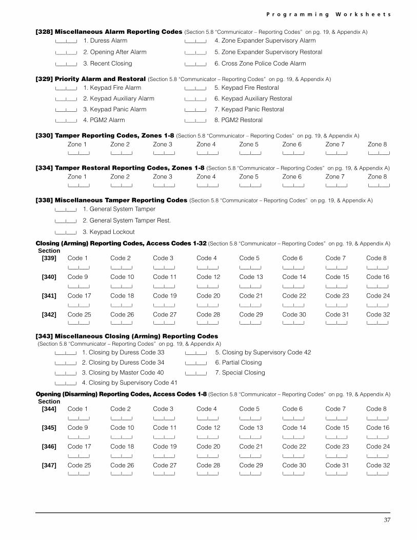
P r o g r a m m i n g W o r k s h e e t s
37
[328] Miscellaneous Alarm Reporting Codes (Section 5.8 “Communicator – Reporting Codes” on pg. 19, & Appendix A)
I_______I_______I 1. Duress Alarm I_______I_______I 4. Zone Expander Supervisory Alarm
I_______I_______I 2. Opening After Alarm I_______I_______I 5. Zone Expander Supervisory Restoral
I_______I_______I 3. Recent Closing I_______I_______I 6. Cross Zone Police Code Alarm
[329] Priority Alarm and Restoral (Section 5.8 “Communicator – Reporting Codes” on pg. 19, & Appendix A)
I_______I_______I 1. Keypad Fire Alarm I_______I_______I 5. Keypad Fire Restoral
I_______I_______I 2. Keypad Auxiliary Alarm I_______I_______I 6. Keypad Auxiliary Restoral
I_______I_______I 3. Keypad Panic Alarm I_______I_______I 7. Keypad Panic Restoral
I_______I_______I 4. PGM2 Alarm I_______I_______I 8. PGM2 Restoral
[330] Tamper Reporting Codes, Zones 1-8 (Section 5.8 “Communicator – Reporting Codes” on pg. 19, & Appendix A)
Zone 1 Zone 2 Zone 3 Zone 4 Zone 5 Zone 6 Zone 7 Zone 8 I_______I_______I I_______I_______I I_______I_______I I_______I_______I I_______I_______I I_______I_______I I_______I_______I I_______I_______I
[334] Tamper Restoral Reporting Codes, Zones 1-8 (Section 5.8 “Communicator – Reporting Codes” on pg. 19, & Appendix A)
Zone 1 Zone 2 Zone 3 Zone 4 Zone 5 Zone 6 Zone 7 Zone 8 I_______I_______I I_______I_______I I_______I_______I I_______I_______I I_______I_______I I_______I_______I I_______I_______I I_______I_______I
[338] Miscellaneous Tamper Reporting Codes (Section 5.8 “Communicator – Reporting Codes” on pg. 19, & Appendix A)
I_______I_______I 1. General System Tamper
I_______I_______I 2. General System Tamper Rest.
I_______I_______I 3. Keypad Lockout
Closing (Arming) Reporting Codes, Access Codes 1-32 (Section 5.8 “Communicator – Reporting Codes” on pg. 19, & Appendix A)Section
[339] Code 1 Code 2 Code 3 Code 4 Code 5 Code 6 Code 7 Code 8 I_______I_______I I_______I_______I I_______I_______I I_______I_______I I_______I_______I I_______I_______I I_______I_______I I_______I_______I
[340] Code 9 Code 10 Code 11 Code 12 Code 13 Code 14 Code 15 Code 16 I_______I_______I I_______I_______I I_______I_______I I_______I_______I I_______I_______I I_______I_______I I_______I_______I I_______I_______I
[341] Code 17 Code 18 Code 19 Code 20 Code 21 Code 22 Code 23 Code 24I_______I_______I I_______I_______I I_______I_______I I_______I_______I I_______I_______I I_______I_______I I_______I_______I I_______I_______I
[342] Code 25 Code 26 Code 27 Code 28 Code 29 Code 30 Code 31 Code 32I_______I_______I I_______I_______I I_______I_______I I_______I_______I I_______I_______I I_______I_______I I_______I_______I I_______I_______I
[343] Miscellaneous Closing (Arming) Reporting Codes (Section 5.8 “Communicator – Reporting Codes” on pg. 19, & Appendix A)
I_______I_______I 1. Closing by Duress Code 33 I_______I_______I 5. Closing by Supervisory Code 42
I_______I_______I 2. Closing by Duress Code 34 I_______I_______I 6. Partial Closing
I_______I_______I 3. Closing by Master Code 40 I_______I_______I 7. Special Closing
I_______I_______I 4. Closing by Supervisory Code 41
Opening (Disarming) Reporting Codes, Access Codes 1-8 (Section 5.8 “Communicator – Reporting Codes” on pg. 19, & Appendix A)Section
[344] Code 1 Code 2 Code 3 Code 4 Code 5 Code 6 Code 7 Code 8 I_______I_______I I_______I_______I I_______I_______I I_______I_______I I_______I_______I I_______I_______I I_______I_______I I_______I_______I
[345] Code 9 Code 10 Code 11 Code 12 Code 13 Code 14 Code 15 Code 16 I_______I_______I I_______I_______I I_______I_______I I_______I_______I I_______I_______I I_______I_______I I_______I_______I I_______I_______I
[346] Code 17 Code 18 Code 19 Code 20 Code 21 Code 22 Code 23 Code 24I_______I_______I I_______I_______I I_______I_______I I_______I_______I I_______I_______I I_______I_______I I_______I_______I I_______I_______I
[347] Code 25 Code 26 Code 27 Code 28 Code 29 Code 30 Code 31 Code 32I_______I_______I I_______I_______I I_______I_______I I_______I_______I I_______I_______I I_______I_______I I_______I_______I I_______I_______I

38
[348] Miscellaneous Opening (Disarming) Reporting Codes (Section 5.8 “Communicator – Reporting Codes” on pg. 19, & Appendix A)
I_______I_______I 1. Opening by Duress Code 33 I_______I_______I 5. Opening by Supervisory Code 42
I_______I_______I 2. Opening by Duress Code 34 I_______I_______I 6. Auto Arm Cancellation
I_______I_______I 3. Opening by Master Code 40 I_______I_______I 7. Special Opening
I_______I_______I 4. Opening by Supervisory Code 41
[349] Maintenance Alarm Reporting Codes (Section 5.8 “Communicator – Reporting Codes” on pg. 19, & Appendix A)
I_______I_______I 1. Battery Trouble Alarm I_______I_______I 5. Auxiliary Power Supply Trouble Alarm
I_______I_______I 2. AC Failure Trouble Alarm I_______I_______I 6. For future use
I_______I_______I 3. Bell Circuit Trouble Alarm I_______I_______I 7. General System Trouble
I_______I_______I 4. Fire Trouble Alarm I_______I_______I 8. General System Supervisory
[350] Maintenance Restoral Reporting Codes (Section 5.8 “Communicator – Reporting Codes” on pg. 19, & Appendix A)
I_______I_______I 1. Battery Trouble Restoral I_______I_______I 5. Auxiliary Power Supply Trouble Restoral
I_______I_______I 2. AC Failure Trouble Restoral I_______I_______I 6. TLM Restoral
I_______I_______I 3. Bell Circuit Trouble Restoral I_______I_______I 7. General System Trouble Restore
I_______I_______I 4. Fire Trouble Restoral I_______I_______I 8. General System Supervisory Restore
[351] Miscellaneous Maintenance Reporting Codes (Section 5.8 “Communicator – Reporting Codes” on pg. 19, & Appendix A)
I_______I_______I 1. Telephone Number 1 Failure to Communicate
I_______I_______I 2. Telephone Number 2 Failure to Communicate
I_______I_______I 3. Event Buffer is 75% Full Since Last Upload
I_______I_______I 4. DLS Lead IN
I_______I_______I 5. DLS Lead OUT
I_______I_______I 6. General Zone Trouble Alarm
I_______I_______I 7. General Zone Trouble Restore
I_______I_______I 8. For future use
[352] Test Transmission Reporting Codes (Section 5.8 “Communicator – Reporting Codes” on pg. 19, & Appendix A)
I_______I_______I 1. Periodic Test Transmission I_______I_______I 3. GSM1000 Test Transmission Code*
I_______I_______I 2. System Test
*The GSM1000 Test Transmission Code must be programmed as “00” for the GSM1000 Test Transmission to be disabled.
[353] Wireless Maintenance Reporting Codes (Section 5.8 “Communicator – Reporting Codes” on pg. 19, & Appendix A)
I_______I_______I 1. Wireless Device Low Battery Alarm I_______I_______I 2. Wireless Device Low Battery Restore
[360] Communicator Format Options (Section 5.9 “Communicator – Reporting Formats” on page 20)
NOTE:The Third telephone number follows the format of the First telephone number.
Default04 I_______I_______I 1st/3rd Telephone Number
04 I_______I_______I 2nd Telephone Number
01 20 BPS, 1400 HZ handshake 04 SIA FSK 07 10 BPS, 1400Hz Handshake02 20 BPS, 2300 HZ handshake 05 Pager 08 10 BPS, 2300Hz Handshake03 DTMF CONTACT ID 06 Residential Dial

P r o g r a m m i n g W o r k s h e e t s
39
[361] Alarm/Restore Communicator Call Directions (Section 5.5 “Communicator – Dialing” on page 18)
Default Option ON OFFON I_______I 1 1st Telephone Number Disabled
OFF I_______I 2 2nd Telephone Number Disabled
OFF I_______I 3 1st Telephone Number (via GSM1000) Disabled
OFF I_______I 4 2nd Telephone Number (via GSM1000) Disabled
OFF I_______I 5-8 For future use
[363] Tamper/Restore Communicator Call Directions (Section 5.5 “Communicator – Dialing” on page 18)
Default Option ON OFFON I________I 1 1st Telephone Number Disabled
OFF I________I 2 2nd Telephone Number Disabled
OFF I_______I 3 1st Telephone Number (via GSM1000) Disabled
OFF I_______I 4 2nd Telephone Number (via GSM1000) Disabled
OFF I_______I 5-8 For future use
[365] Opening/Closing Communicator Call Directions (Section 5.5 “Communicator – Dialing” on page 18)
Default Option ON OFFON I________I 1 1st Telephone Number Disabled
OFF I________I 2 2nd Telephone Number Disabled
OFF I_______I 3 1st Telephone Number (via GSM1000) Disabled
OFF I_______I 4 2nd Telephone Number (via GSM1000) Disabled
OFF I_______I 5-8 For future use
[367] System Maintenance Alarm/Restore Communicator Call Directions (Section 5.5 “Communicator – Dialing” on page 18)
Default Option ON OFFON I________I 1 1st Telephone Number Disabled
OFF I________I 2 2nd Telephone Number Disabled
OFF I_______I 3 1st Telephone Number (via GSM1000) Disabled
OFF I_______I 4 2nd Telephone Number (via GSM1000) Disabled
OFF I_______I 5-8 For future use
[368] System Test Transmissions Communicator Call Directions (Section 5.5 “Communicator – Dialing” on page 18)
Default Option ON OFFOFF I________I 1 1st Telephone Number Disabled
OFF I________I 2 2nd Telephone Number Disabled
OFF I_______I 3 1st Telephone Number (via GSM1000) Disabled
OFF I_______I 4 2nd Telephone Number (via GSM1000) Disabled
OFF I_______I 5-8 For future use
NOTE:The GSM1000 backup call directions will only back up their respective telephone numbers.

40
[370] Communication VariablesDefault Section Page #
005 I_______I_______I_______I Swinger Shutdown (Alarms and Rest) (001-014 Transmissions, 000=disabled) 5.19 26
005 I_______I_______I_______I Swinger Shutdown (Tampers and Rest)(001-014 Transmissions, 000=disabled) 5.19 26
005 I_______I_______I_______I Swinger Shutdown (Maint and Rest) (001-014 Transmissions, 000=disabled) 5.19 26
000 I_______I_______I_______I Transmission Delay (001-255 seconds) 5.15 25
030 I_______I_______I_______I AC Failure Communication Delay (001-255 minutes) 5.8 19
003 I_______I_______I_______I TLM Trouble Delay (No. of checks required - valid entries 003 - 255) 5.12 24
030 I_______I_______I_______I Test Transmission Cycle (land line) (001-255 minutes/days)† 5.14 24
030 I_______I_______I_______I For future use
007 I_______I_______I_______I Zone Low Battery Transmission Delay (000-255 days) 5.8 19†Depends on programming in section [702], option [3].NOTE: To program [000] for immediate AC failure reporting.
[371] Test Transmission Time of Day (Section 5.14 “Test Transmission” on page 24)
NOTE: If the land line test transmission cycle is programmed in minutes (section [702], option [3]), this section will not affect the landline test transmission cycle.
Default9999 I_______I_______I_______I_______I (Valid entries are 0000-2359, 9999 to disable)
[380] First Communicator Option Code Default Option ON Off Section Page #
ON I_______I 1 Communications Enabled Communications Disabled 5.5 18
OFF I_______I 2 Restorals on Bell Time-out Restorals Follow Zones 5.8 19
OFF I_______I 3 Pulse Dialing DTMF Dialing 5.5 18
OFF I_______I 4 Switch to Pulse Dialing on 5th Attempt DTMF Dial For All Attempts 5.5 18
ON I_______I 5 3rd Telephone Number enabled 3rd Telephone Number disabled 5.7 19
ON I_______I 6 Alternate Dial (1st and 3rd) Call 1st Number, Backup to 3rd 5.7 19
OFF I_______I 7 Call GSM1000 as well as Land Line GSM1000 is Backup of Land Line(s) 5.26 27
OFF I_______I 8 For future use
[381] Second Communicator Option CodeDefault Option ON Off Section Page #
OFF I_______I 1 Open After Alarm Kypd Ringback Enabled Open After Alrm Kypd Ringback Disabled 5.17 25
OFF I_______I 2 Open After Alarm Bell Ringback Enabled Open After Alrm Bell Ringback Disabled 5.17 25
OFF I_______I 3 SIA Sends Programmed Rep. Codes SIA Sends Automatic Rep. Codes 5.9
OFF I_______I 4 Closing Confirmation Enabled Closing Confirmation Disabled 5.17 25
ON I_______I 5 Talk/Listen (PC5938) on Phone Lines 1/3 No Talk/Listen (PC5938) on Phone Lines 1/35.7 19
OFF I_______I 6 Talk/Listen (PC5938) on Phone Line 2 No Talk/Listen (PC5938) on Phone Line 2 5.7 19
ON I_______I 7 Contact ID Uses Programmed Reporting CodesContact ID Uses Auto Reporting Codes 5.9 20
OFF I_______I 8 For future use —
[390] GSM1000 Preamble (First Telephone Number) (Section 5.26 “GSM1000 Cellular Communicator” on page 27)
Default: FFFF I_______I_______I_______I_______I (Program all unused digits with Hex F)
[391] GSM1000 Preamble (Second Telephone Number) (Section 5.26 “GSM1000 Cellular Communicator” on page 27)
Default: FFFF I_______I_______I_______I_______I (Program all unused digits with Hex F)
[392] GSM1000 Preamble (Third Telephone Number) (Section 5.26 “GSM1000 Cellular Communicator” on page 27)
Default: FFFF I_______I_______I_______I_______I (Program all unused digits with Hex F)
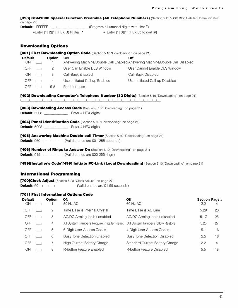
P r o g r a m m i n g W o r k s h e e t s
41
[393] GSM1000 Special Function Preamble (All Telephone Numbers) (Section 5.26 “GSM1000 Cellular Communicator” on page 27)
Default: FFFFFF I_______I_______I_______I_______I_______I_______I (Program all unused digits with Hex F)
•Enter [*][2][*] (HEX B) to dial [*] • Enter [*][3][*] (HEX C) to dial [#]
Downloading Options
[401] First Downloading Option Code (Section 5.10 “Downloading” on page 21)
Default Option ON OffON I_______I 1 Answering Machine/Double Call Enabled Answering Machine/Double Call Disabled
OFF I_______I 2 User Can Enable DLS Window User Cannot Enable DLS Window
ON I_______I 3 Call-Back Enabled Call-Back Disabled
OFF I_______I 4 User-initiated Call-up Enabled User-initiated Call-up Disabled
OFF I_______I 5-8 For future use
[402] Downloading Computer’s Telephone Number (32 Digits) (Section 5.10 “Downloading” on page 21)I_____I_____I_____I_____I_____I_____I_____I_____I_____I_____I_____I_____I_____I_____I_____I_____I_____I_____I_____I_____I_____I_____I_____I_____I_____I_____I_____I_____I_____I_____I_____I_____I
[403] Downloading Access Code (Section 5.10 “Downloading” on page 21)
Default: 5008 I_______I_______I_______I_______I Enter 4 HEX digits
[404] Panel Identification Code (Section 5.10 “Downloading” on page 21)
Default: 5008 I_______I_______I_______I_______I Enter 4 HEX digits
[405] Answering Machine Double-call Timer (Section 5.10 “Downloading” on page 21)
Default: 060 I_______I_______I_______I (Valid entries are 001-255 seconds)
[406] Number of Rings to Answer On (Section 5.10 “Downloading” on page 21)
Default: 015 I_______I_______I_______I (Valid entries are 000-255 rings)
[499][Installer’s Code][499] Initiate PC-Link (Local Downloading) (Section 5.10 “Downloading” on page 21)
International Programming
[700]Clock Adjust (Section 5.28 “Clock Adjust” on page 27)
Default: 60 I_______I_______I (Valid entries are 01-99 seconds)
[701] First International Options Code Default Option ON Off Section Page #
ON I_______I 1 50 Hz AC 60 Hz AC 2.2 4
OFF I_______I 2 Time Base is Internal Crystal Time Base is AC Line 5.29 28
OFF I_______I 3 AC/DC Arming Inhibit enabled AC/DC Arming Inhibit disabled 5.17 25
OFF I_______I 4 All System Tampers Require Installer Reset All System Tampers follow Restore 5.25 27
OFF I_______I 5 6-Digit User Access Codes 4-Digit User Access Codes 5.1 16
OFF I_______I 6 Busy Tone Detection Enabled Busy Tone Detection Disabled 5.5 18
OFF I_______I 7 High Current Battery Charge Standard Current Battery Charge 2.2 4
ON I_______I 8 R-button Feature Enabled R-button Feature Disabled 5.5 18

42
[702] Second International Options Code Default Option ON Off Section Page #
OFF I_______I 1 Pulse Dialing Make/Break Ratio is 33/67 Pulse Dialing Make/Break Ratio is 40/60 5.5 18
OFF I_______I 2 Force Dialing enabled Force Dialing disabled 5.5 18
OFF I_______I 3 Land line Test Transmission in minutes Land line Test Transmission in days 5.14 24
OFF I_______I 4 1600 Hz Handshake Standard Handshake 5.9 20
OFF I_______I 5 ID Tone enabled ID Tone disabled 5.5 18
OFF I_______I 6 2100 HZ ID Tone 1300 Hz ID Tone 5.5 18
OFF I_______I 7 One Time 1-Hr User enabled DLS Window Full 6-Hr User enabled DLS Window 5.10 21
OFF I_______I 8 Bell on FTC when armed FTC Trouble only when armed 5.5 18
[703] Delay Between Dialing Attempts (Section 5.5 “Communicator – Dialing” on page 18)
Default: 001 I_________I________I________I (Valid entries are 000-255 Seconds)
Module Programming
[801] PC5400 Printer Module Programming Please refer to your PC5400 Installation Manual for installation and programming instructions.
[802] PC59XX Audio Interface Programming Please refer to your PC59XX Installation Manual for installation and programming instructions.
[803]For future use
[804] PC5132 Wireless Expansion ProgrammingPlease refer to your PC5132 Installation Manual for programming locations and instructions.
Special Installer Functions
[901] Installer Walk Test Mode Enable / Disable (Section 5.32 “Walk Test (Installer)” on page 28)
[902] Module Supervision Reset (Section 2.7 “Removing Modules” on page 6)
[903] Module Supervision Field (Section 2.6 “Supervision” on page 6)
[904] Wireless Module Placement Test For more information, please refer to your PC5132 Installation Manual
• Select the module / transmitter (Zones 01-8).• Press [#] to Cancel.
Placement Led Keypad LCD Keypad Bell / BuzzerGood Light 1 ON Steady “GOOD” 1 Beep / SquawkFair Light 2 ON Steady “FAIR” 2 Beeps / SquawksBad Light 3 ON Steady “BAD” 3 Beeps / Squawks
[990] Installer Lockout Enable (Section 5.31 “Installer’s Lockout” on page 28)
[991] Installer Lockout Disable (Section 5.31 “Installer’s Lockout” on page 28)
[993]For future use
[995] Restore Escort5580 Factory Default Programming (Section 5.30 “Resetting Factory Defaults” on page 28)
[996] Restore PC5132 Factory Default Programming (Section 5.30 “Resetting Factory Defaults” on page 28)
[997] Restore PC5400 Factory Default Programming (Section 5.30 “Resetting Factory Defaults” on page 28)
[998] Restore PC59XX Factory Default Programming (Section 5.30 “Resetting Factory Defaults” on page 28)
[999] Restore PC5008 Factory Default Programming (Section 5.30 “Resetting Factory Defaults” on page 28)

43
Appendix A: Reporting CodesThe following tables contain Contact ID and Automatic SIA for-mat reporting codes. For more information on reporting codeformats and notes about individual reporting codes, see sec-tions 5.8 “Communicator – Reporting Codes” on page 19 and5.9 “Communicator – Reporting Formats” on page 20.
Contact IDThe first digit (in parentheses) will automatically be sent by thecontrol. The second two digits are programmed to indicatespecific information about the signal.For example, if zone 1 is an entry/exit point, you could pro-gram the event code as [34]. The central station wouldreceive the following:
*BURG - ENTRY/EXIT - 1where the “1” indicates which zone went into alarm.
SIA Format - Level 2 (Hardcoded)The SIA communication format used in this product follows thelevel 2 specifications of the SIA Digital Communication Stan-dard - January 1996. This format will send the Account Codealong with its data transmission. The transmission would looksimilar to the following at the receiver:
N Ri01 BA 01N = New Event
Ri01 = Partition /Area IdentifierBA = Burglary Alarm01 = Zone 1
Section # Reporting Code Code Sent When...Dialer
Direction*Contact
ID CodesSIA Auto Rep
Codes**
[320] Zone Alarms zone goes into alarm A/R (1) 3A See Table 3[324] Zone Restorals alarm condition has been restored A/R (1) 3A[330][334]
Zone Tamper/Restoral zone exhibits a tamper condition/tamper conditionrestored
T/R (1) 44 TA-ZZ/TR-ZZ
[328] Duress Alarm duress code entered at keypad A/R (1) 21 HA-00[328] Opening After Alarm system disarmed with alarm in memory A/R (4) A6 OR-00[328] Recent Closing alarm occurs within two minutes of system arming A/R (4) 59 CR-00[328] Zone Expander Supervisory
Alarm/Rest.panel loses/restores supervisory transmission over theKeybus from enrolled PC5132 module or keypads withzone inputs
A/R (1) 43 UA-00/UH-00
[328] Cross Zone (Police Code)Alarm
two zones on the same partition go into alarm duringany given armed-to-armed period (incl. 24Hr zones)
A/R (1) 4A BV-00
[329] [F] Key Alarm/Rest. Keypad fire alarm (alarm and restore rep. codes senttogether)
A/R (1) 15 FA-00/FH-00
[329] [A] Key Alarm/Rest. Keypad auxiliary alarm (alarm and restore rep. codessent together)
A/R (1) AA MA-00/MH-00
[329] [P] Key Alarm/Rest. Keypad panic alarm (alarm and restore rep. codes senttogether)
A/R (1) 2A PA-00/PH-00
[329] PGM2 Alarm/Rest. a panic button wired to PGM2 is pressed / access codeis entered (PGM2 programmed as option [23] or [24])
A/R (1) 4A UA-99/UH-99
[338] General System Tamper/Rest.
enrolled module with tamper inputs has a tamper alarm/all module tampers restored
T/R (1) 45 TA-00/TR-00
[338] Keypad Lockout max. number of incorrect access codes has beenentered at a keypad
T/R (4) 21 JA-00
[339-343] Closings system armed (user 01-34, 40-42 indicated) O/C (4) A2 CL-UU[343] Partial Closing one or more zones bypassed when system armed O/C (4) 7A CG-ZZ[343] Special Closing Closing (arming) using one of the following methods:
quick arm, auto arm, keyswitch, function key, guardcode, DLS software
O/C (4) AA CL-00
[344-348] Openings system disarmed (user 01-34, 40-42 indicated) O/C (4) A2 OP-UU[348] Auto Arm Cancellation auto arm cancelled O/C (4) A5 CE-00[348] Special Opening Opening (disarming) using one of the following meth-
ods: keyswitch, guard code, DLS softwareO/C (4) AA OP-00
[349-350] Battery Trouble/Rest. PC5008 battery is low/battery restored MA/R (3) A2 YT-00/YR-00* A/R = alarms/restorals;T/R = tampers/restorals; O/C = openings/closings; MA/R = miscellaneous alarms/restorals; T = test transmissions
** UU = user number (user01-42); ZZ = zone number (01-08)

44
Table2: Contact ID Zone Alarm/Restoral Event Codes (as per ADEMCO):Program any of these codes for zone alarms/restorals when usingthe standard (non-automatic) Contact ID reporting format.
Table 3: SIA Format Automatic Zone Alarm/Restoral Codes
Section # Reporting Code Code Sent When...Dialer
Direction*Contact
ID CodesSIA Auto Rep
Codes**
[349-350] AC Line Trouble/Rest. AC power to control panel is disconnected or inter-rupted/AC power restored (Both codes follow AC Fail-ure Comm. Delay.)
MA/R (3) A1 AT-00/AR-00
[349-350] Main Bell Trouble/Rest. open circuit detected across bell terminals/bell circuitclosed
MA/R (3) 21 UT-99/UJ-99
[349-350] Fire Trouble/Rest. a trouble occurs/restores on a fire zone MA/R (3) 73 FT-00/FJ-00[349-350] Auxiliary Power Trouble/
Rest.aux voltage supply trouble/restoral MA/R (3) AA YP-00/YQ-00
[350] TLM Restore Telephone line trouble restore MA/R (3) 51 LR-00[349-350] Gen System Trouble/Rest. “Service Required” trouble occurs (view troubles using
[*][2])/trouble restoredMA/R (3) 33 ET-00/ER-00
[349-350] Gen System SupervisoryTrouble/Rest.
control panel loses/restores communications with mod-ule(s) connected to the Keybus
MA/R (3) 33 ET-00/ER-00
[351] Line 1 or 2 FTC Restoral control panel has restored communications to centralstation on line 1 or 2 (after FTC)
MA/R (3) 54 YK-00
[351] Event Buffer is 75% Full event buffer is almost full since last upload MA/R (6) 23 JL-00[351] DLS Lead In downloading session start MA/R (4) 11 RB-00[351] DLS Lead Out downloading session complete MA/R (4) 12 RS-00[351] Zone Fault/Rest. one or more zones have fault/fault restored MA/R (3) 72 UT-00/UJ-00[352] Periodic Test periodic system test transmission T (6) A2 RP-00[352] System Test [*][6] bell/communications test T (6) A1 RX-00[353] Wireless Device Low Battery
Trouble/Rest.wireless zones (WLS904, WLS905, WLS907); panicpendants (WLS908); handheld keypads (WLS910);wireless keys (WLS909) have low battery/all low batter-ies restored
MA/R (3) 84 XT-00/XR-00
* A/R = alarms/restorals;T/R = tampers/restorals; O/C = openings/closings; MA/R = miscellaneous alarms/restorals; T = test transmissions** UU = user number (user01-42); ZZ = zone number (01-08)
Medical Alarms (1)34 Entry / Exit(1)AA Medical (1)35 Day / Night(1)A1 Pendant Transmitter (1)36 Outdoor(1)A2 Fail to Report In (1)37 TamperFire Alarms (1)38 Near Alarm(1)1A Fire Alarm General Alarms(1)11 Smoke (1)4A General Alarm(1)12 Combustion (1)43 Exp. module failure(1)13 Water Flow (1)44 Sensor tamper(1)14 Heat (1)45 Module Tamper(1)15 Pull Station (1)4A Cross Zone Police Code(1)16 Duct 24 Hour Non-Burglary(1)17 Flame (1)5A 24 Hour non-Burg(1)18 Near Alarm (1)51 Gas detectedPanic Alarms (1)52 Refrigeration(1)2A Panic (1)53 Loss of Heat(1)21 Duress (1)54 Water Leakage(1)22 Silent (1)55 Foil Break(1)23 Audible (1)56 Day TroubleBurglar Alarms (1)57 Low bottled Gas level(1)3A Burglary (1)58 High Temp(1)31 Perimeter (1)59 Low Temp(1)32 Interior (1)61 Loss of Air Flow(1)33 24 Hour
Zone DefinitionSIA Auto Rep
Codes*
Zone Alm/Rest.
Delay, Instant, Interior, DelayStay/Away, Interior Stay/Away,24Hr Burg.
BA-ZZ/BH-ZZ
Standard 24Hr Fire, Delayed24Hr Fire
FA-ZZ/FH-ZZ
24Hr Supervisory US-ZZ/UR-ZZ
24Hr Supervisory Buzzer UA-ZZ/UH-ZZ
24Hr Sprinkler SA-ZZ/SH-ZZ
24Hr Gas GA-ZZ/GH-ZZ
24Hr Heat KA-ZZ/KH-ZZ
24Hr Medical MA-ZZ/MH-ZZ
24Hr Emergency (non-medical) QA-ZZ/QH-ZZ
24Hr Waterflow WA-ZZ/WH-ZZ
24Hr Freeze ZA-ZZ/ZH-ZZ
24Hr Holdup HA-ZZ/HH-ZZ
24Hr Panic PA-ZZ/PH-ZZ
Latching 24Hr, 24-Hr Bell/Buzzer BA-ZZ/BH-ZZ
* ZZ = zones 01-08

45
Appendix B: Programming LCD Keypads
If you have an LCD5500Z Keypad, additional programming is required for proper operation. The following is a description of the available programming options and their accompanying programming sections:
How to Enter LCD ProgrammingFollow the programming procedure as outlined in Section 4 by pressing [*][8][Installer’s Code]. Press the [*] key. Enter the two digit Section number to be programmed.
Programmable Labels – Sections [01] - [08], [33], [34], [40], [44], [51], [52]Zone labels and other LCD display identifiers can be customized to make operation of the system easier for the end user. The fol-lowing procedure should be used for creating all LCD labels:
• Enter Installer’s Programming. Enter the Number corresponding to the label to be programmed.• Use the arrow keys (<>) to move the underline bar underneath the letter to be changed. • Press the number key [1] to [9] corresponding to the letter you require. The first time you press the number the first letter will
appear. Pressing the number key again will display the next letter. Refer to the following chart:[1] - A, B, C, 1 [2] - D, E, F, 2 [3] - G, H, I, 3 [4] - J, K, L, 4 [5] - M, N, O, 5[6] - P, Q, R, 6 [7] - S, T, U, 7 [8] - V, W, X, 8 [9] - Y, Z, 9,0 [0] - Space
• When the required letter or number is displayed use the arrow keys (<>) to scroll to the next letter.• When you are finished programming the label, press the [*] key, scroll to “Save,” then press [*].• Continue from Step 2 until all labels are programmed.[01] to [08] Zone Labels (14 Characters)
Default: “Zone 1” I_____I_____I_____I_____I_____I_____I_____I_____I_____I_____I_____I_____I_____I_____I
Default: “Zone 2” I_____I_____I_____I_____I_____I_____I_____I_____I_____I_____I_____I_____I_____I_____I
Default: “Zone 3” I_____I_____I_____I_____I_____I_____I_____I_____I_____I_____I_____I_____I_____I_____I
Default: “Zone 4” I_____I_____I_____I_____I_____I_____I_____I_____I_____I_____I_____I_____I_____I_____I
Default: “Zone 5” I_____I_____I_____I_____I_____I_____I_____I_____I_____I_____I_____I_____I_____I_____I
Default: “Zone 6” I_____I_____I_____I_____I_____I_____I_____I_____I_____I_____I_____I_____I_____I_____I
Default: “Zone 7” I_____I_____I_____I_____I_____I_____I_____I_____I_____I_____I_____I_____I_____I_____I
Default: “Zone 8” I_____I_____I_____I_____I_____I_____I_____I_____I_____I_____I_____I_____I_____I_____I
[33] Fire Alarm Label (14 Characters)Default: “Fire Zone” I_____I_____I_____I_____I_____I_____I_____I_____I_____I_____I_____I_____I_____I_____I
[34] System Label (14 Characters)Default: “System” I_____I_____I_____I_____I_____I_____I_____I_____I_____I_____I_____I_____I_____I_____I
[40] to [48] [*][7][1-4] Command Output Option Labels (14 Characters)[40] Default: “Command O/P 1”I_____I_____I_____I_____I_____I_____I_____I_____I_____I_____I_____I_____I_____I_____I
[44] Default: “Command O/P 2”I_____I_____I_____I_____I_____I_____I_____I_____I_____I_____I_____I_____I_____I_____I
[46] Default: “Command O/P 3”I_____I_____I_____I_____I_____I_____I_____I_____I_____I_____I_____I_____I_____I_____I
[48] Default: “Command O/P 4”I_____I_____I_____I_____I_____I_____I_____I_____I_____I_____I_____I_____I_____I_____I
[51] Fail to Arm Event MessageDefault: “System Has Failed to Arm” I_____I_____I_____I_____I_____I_____I_____I_____I_____I_____I_____I_____I_____I_____I
[52] Alarm When Armed Event MessageDefault: “Alarm Occurred While Armed < >”I_____I_____I_____I_____I_____I_____I_____I_____I_____I_____I_____I_____I_____I_____I
[60] First User Display MaskDefault Option ON OFF
ON I_______I 1 Hold [P]anic Keys prompt ON Hold [P]anic Keys prompt OFF
ON I_______I 2 Zone Bypassing prompt ON Zone Bypass prompt OFF
ON I_______I 3 Troubles prompt ON Troubles prompt OFF
ON I_______I 4 Alarm Memory prompt ON Alarm Memory prompt OFF
ON I_______I 5 Door Chime Control prompt ON Door Chime Control prompt OFF
ON I_______I 6 Access Codes prompt ON Access Codes prompt OFF
ON I_______I 7 User Functions prompt ON User Functions prompt OFF
ON I_______I 8 Output Control prompt ON Output Control prompt OFF
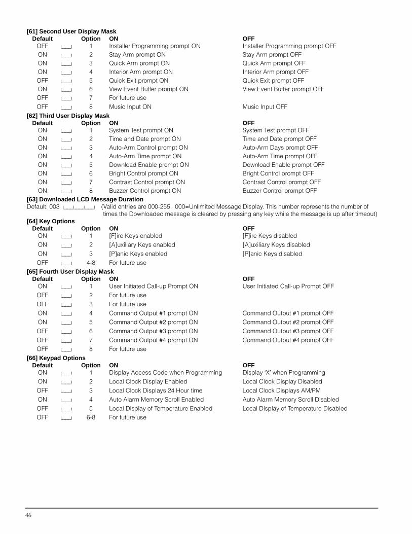
46
[61] Second User Display MaskDefault Option ON OFF
OFF I_______I 1 Installer Programming prompt ON Installer Programming prompt OFFON I_______I 2 Stay Arm prompt ON Stay Arm prompt OFFON I_______I 3 Quick Arm prompt ON Quick Arm prompt OFFON I_______I 4 Interior Arm prompt ON Interior Arm prompt OFFOFF I_______I 5 Quick Exit prompt ON Quick Exit prompt OFFON I_______I 6 View Event Buffer prompt ON View Event Buffer prompt OFFOFF I_______I 7 For future useOFF I_______I 8 Music Input ON Music Input OFF
[62] Third User Display MaskDefault Option ON OFF
ON I_______I 1 System Test prompt ON System Test prompt OFFON I_______I 2 Time and Date prompt ON Time and Date prompt OFFON I_______I 3 Auto-Arm Control prompt ON Auto-Arm Days prompt OFFON I_______I 4 Auto-Arm Time prompt ON Auto-Arm Time prompt OFFON I_______I 5 Download Enable prompt ON Download Enable prompt OFFON I_______I 6 Bright Control prompt ON Bright Control prompt OFFON I_______I 7 Contrast Control prompt ON Contrast Control prompt OFFON I_______I 8 Buzzer Control prompt ON Buzzer Control prompt OFF
[63] Downloaded LCD Message DurationDefault: 003 I_______I_______I_______I (Valid entries are 000-255, 000=Unlimited Message Display. This number represents the number of
times the Downloaded message is cleared by pressing any key while the message is up after timeout)[64] Key Options
Default Option ON OFFON I_______I 1 [F]ire Keys enabled [F]ire Keys disabledON I_______I 2 [A]uxiliary Keys enabled [A]uxiliary Keys disabledON I_______I 3 [P]anic Keys enabled [P]anic Keys disabledOFF I_______I 4-8 For future use
[65] Fourth User Display MaskDefault Option ON OFF
ON I_______I 1 User Initiated Call-up Prompt ON User Initiated Call-up Prompt OFFOFF I_______I 2 For future useOFF I_______I 3 For future useON I_______I 4 Command Output #1 prompt ON Command Output #1 prompt OFFON I_______I 5 Command Output #2 prompt ON Command Output #2 prompt OFFOFF I_______I 6 Command Output #3 prompt ON Command Output #3 prompt OFFOFF I_______I 7 Command Output #4 prompt ON Command Output #4 prompt OFFOFF I_______I 8 For future use
[66] Keypad OptionsDefault Option ON OFF
ON I_______I 1 Display Access Code when Programming Display ‘X’ when ProgrammingON I_______I 2 Local Clock Display Enabled Local Clock Display Disabled OFF I_______I 3 Local Clock Displays 24 Hour time Local Clock Displays AM/PMON I_______I 4 Auto Alarm Memory Scroll Enabled Auto Alarm Memory Scroll DisabledOFF I_______I 5 Local Display of Temperature Enabled Local Display of Temperature DisabledOFF I_______I 6-8 For future use

P r o g r a m m i n g L C D K e y p a d s
47
[67] Fifth User Display MaskDefault Option ON OFF
OFF I_______I 1 Thermostat CTRL Prompt ON Thermostat CTRL Prompt OFFOFF I_______I 2 Temperature Setting Prompt ON Temperature Setting Prompt OFFOFF I_______I 3 Occupancy Mode Prompt ON Occupancy Mode Prompt OFFOFF I_______I 4 Thermostat Mode Prompt ON Thermostat Mode Prompt OFFOFF I_______I 5 Fan Control Prompt ON Fan Control Prompt OFFOFF I_______I 6 For Keypad View Prompt ON For Keypad View Prompt OFFOFF I_______I 7-8 For future use
[68] Sixth User Display MaskDefault Option ON OFF
OFF I_______I 1 Occupancy Mode Auxiliary Prompt ON Occupancy Mode Auxiliary Prompt OFFOFF I_______I 2 Occupancy Mode Day Prompt ON Occupancy Mode Day Prompt OFFOFF I_______I 3 Occupancy Mode Away Prompt ON Occupancy Mode Away Prompt OFFOFF I_______I 4 Occupancy Mode Night Prompt ON Occupancy Mode Night Prompt OFFOFF I_______I 5-8 For future use
[97] View Software Version[98] Initiate Global Label BroadcastAll LCD programming is done per keypad. If more than one LCD keypad are present on the system, and the PC5400 receives labels, labels pro-grammed at one keypad can be broadcast to all other LCD keypads. Perform the following procedure in order to broadcast labels:Step 1 - Program one LCD keypad completely.Step 2 - Make sure all LCD keypads are connected to the Keybus.Step 3 - Enter Installer’s Programming, then enter Section [98] at the keypad that was programmed. The keypad will now broadcast all the informa-tion programmed to all the other LCD keypads on the system.Step 4 - When the keypad is finished press the [#] key to exit.
[99] Reset LCD EEPROM to Factory Defaults
ASCII Characters

Module Compatible? Comments
Escort5580 Yes
PC5204 Yes
PC5208 Yes
PC5108 No
PC5108L No
PC5132 v1.X Yes No support for Wireless Keys, Pendants or Handheld Keypads
PC5132 v2.X Yes No identified Wireless Keys support
PC5132 v3.X Yes
PC5506 No
PC5508 Yes No Keypad zone support
PC5508Z Yes
LCD5500 v1.X Yes No Keypad zone support; Some display messages not supported
LCD5500Z v2.X Yes
PC5908 Yes
PC5928 Yes
PC5400 v1.X to v2.1 Yes Some printing messages not supported
PC5400 v2.2 Yes
DLM-1 No
DLM-4 v1.x No
DLM-4 v1.0L No
DLM-7 No
©1999 Digital Security Controls Ltd.Toronto, Canada • Tech Line: 1-800-387-3630www.dscgrp.comPrinted in Canada 29003982 R003
PC5008 v2.1C Module Compatibility
Changes for PC5008 v2.1CThe PC5008 v2.1C software incorporates several new fea-tures and changes. The most important additions arelisted here:
Automatic Arming• Auto-arm pre-alert is 5 minutes• Auto-arm postpone featureSee 3.3 “Automatic Arming” on page 9.
New PGM Output Types• [26] Battery Test Output• [27] Police Code Output• [28] Holdup Output• [29] Zone Follower OutputSee 5.11 “PGM Output Options” on page 22.
New Zone Types• [28] 24-Hr Bell/Buzzer• [29] Instant Stay/AwaySee 5.2 “Zone Programming” on page 16.
New Access Code Types• Guard CodeSee 5.1 “Programming Security Codes” on page 16.• One-time Use CodeSee “[*][5] Programming Access Codes” on page 11.
New Options• Troubles are Latching • AC Trouble Beeps Enable/Disable(See “[*][2] Trouble Display” on page 10.)• Automatic Battery Check (See 2.2 “Terminal Descrip-
tions” on page 4.)
Communicator Changes• R-button Dialing Feature (See 5.5 “Communicator –
Dialing” on page 18.)• 6-digit account numbers (See 5.6 “Communicator –
Account Numbers” on page 19.)• Residential Dial format (See 5.9 “Communicator –
Reporting Formats” on page 20.)
New Downloading SoftwareDownloading software DLS-1 v6.3S must be used. Do notattempt to perform downloading/uploading functions withother software versions.
Default Changes• Section [006], Installer’s code: 5555• Section [160], Maximum Number of Dialing Attempts
- valid entries (000-015)