DSB Part B: Important Items for Realizing a High Quality...
18
DSB Part B: Important Items for Realizing a High Quality Electrical Installation Part B3: The four important choices related to the electrical installation Choice No. 2: The cables Identification of Conductors Alphanumeric Color Identification DSB’s advice AC Conductor Terminal Line 1 L1 Black None Line 2 L2 Brown Line 3 L3 Gray Neutral N Blue* DC Conductor Terminal Positive L+ None Red Negative L- None Black Protective Conductor Terminal PE Green/Yellow None PEN Conductor Terminal PEN GN/YE/BU* Protective Bonding Conductor Terminal Unspecified PB Green/Yellow Earthed PBE Unearthed PBU Functional Earthing Conductor Terminal** FE None Green/Yellow *Light blue **For System Earth Terminals Refer to IEC 60445 (2010-08) Part B3: The four important choices related to the electrical installation Choice No. 3: The cable glands Guidance table for selection of cable glands related to basic cable type: Basic cable type Circuit Type Normal ”run through” type gland Screen type gland Exe “run through” type gland* Exd gland
Transcript of DSB Part B: Important Items for Realizing a High Quality...
DSB Part B: Important Items for Realizing a High Quality Electrical Installation
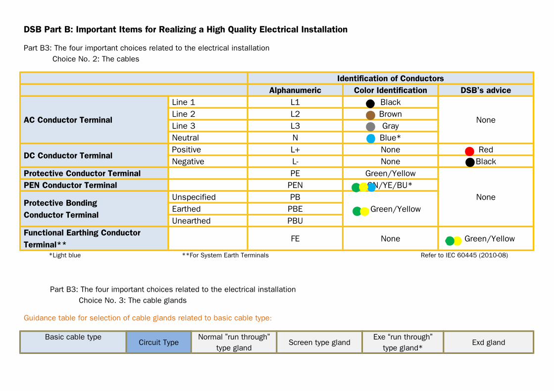
Part B3: The four important choices related to the electrical installation Choice No. 2: The cables
Identification of ConductorsAlphanumeric Color Identification DSB’s advice
AC Conductor Terminal
Line 1 L1 Black
NoneLine 2 L2 BrownLine 3 L3 GrayNeutral N Blue*
DC Conductor TerminalPositive L+ None RedNegative L- None Black
Protective Conductor Terminal PE Green/Yellow
NonePEN Conductor Terminal PEN GN/YE/BU*
Protective BondingConductor Terminal
Unspecified PB Green/YellowEarthed PBE
Unearthed PBUFunctional Earthing Conductor Terminal**
FE None Green/Yellow
*Light blue **For System Earth Terminals Refer to IEC 60445 (2010-08)
Part B3: The four important choices related to the electrical installation Choice No. 3: The cable glands
Guidance table for selection of cable glands related to basic cable type:
Basic cable typeCircuit Type
Normal ”run through”type gland
Screen type glandExe “run through”
type gland*Exd gland
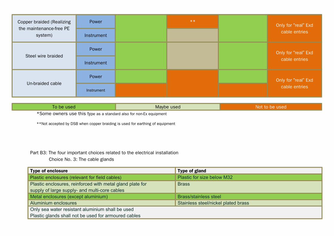
Copper braided (Realizingthe maintenance-free PE
system)
Power **Only for “real” Exd
cable entriesInstrument
Steel wire braidedPower
Only for “real” Exdcable entries
Instrument
Un-braided cablePower
Only for “real” Exdcable entries
Instrument
To be used Maybe used Not to be used*Some owners use this type as a standard also for non-Ex equipment
**Not accepted by DSB when copper braiding is used for earthing of equipment
Part B3: The four important choices related to the electrical installation Choice No. 3: The cable glands
Type of enclosure Type of glandPlastic enclosures (relevant for field cables) Plastic for size below M32
Plastic enclosures, reinforced with metal gland plate forsupply of large supply- and multi-core cables
Brass
Metal enclosures (except aluminium) Brass/stainless steelAluminium enclosures Stainless steel/nickel plated brassOnly sea water resistant aluminium shall be usedPlastic glands shall not be used for armoured cables

For cable glands for explosion protected equipment, see IEC 61892-7Shroud and similar should not be used on cable glands
Refer to IEC 61892-6 (2007):5.6 table 2
Photo left: Remove gland plates, - this will reduce the possibility for earth faults! When “run through” type metal glands are used in a non-metallic enclosure, they will not be looked upon as any exposed conductive part according to DSB’s decision.
This will make the installation (and maintenance) work easier!
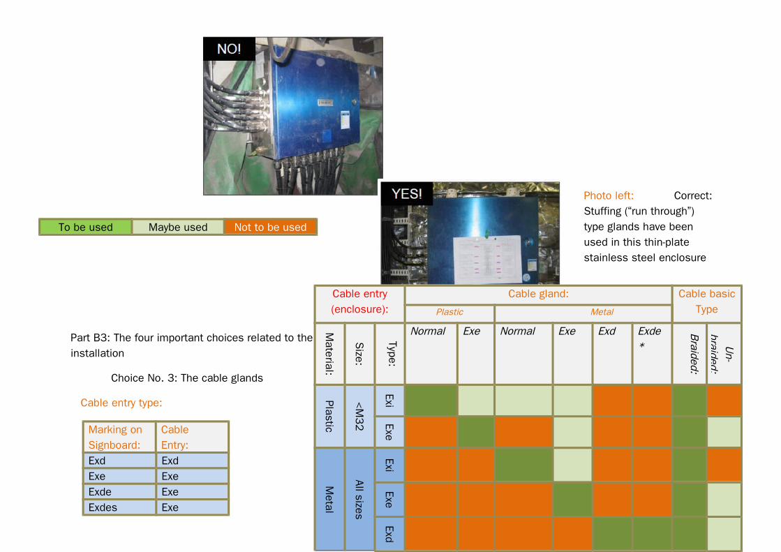
Part B3: The four important choices related to the electrical installation Choice No. 3: The cable glands: Cable entry, gland type and cable type
Guidance table for selection of cable glands in non-ex enclosures:
Photo right: Misuseof EXd glands! Exd glands should not have been usedin this case…
Cable entry(enclosure):
Cable gland: Cable basicType:Plastic Metal
Materia
l
Size
Type
Normal Normal Braided
Un-
braided
Plastic
<M32
Norm
al
Metal
Allsizes
Norm
al
Part B3: The four important choices related to the electricalinstallation
Choice No. 3: The cable glands
Cable entry type: Guidance table for selection of cable glands in explosion protected enclosures:
Marking onSignboard:
CableEntry:
Exd ExdExe ExeExde ExeExdes Exe
Photo left: Correct: Stuffing (“run through”) type glands have been used in this thin-plate stainless steel enclosure
To be used Maybe used Not to be used
Cable entry(enclosure):
Cable gland: Cable basicTypePlastic Metal
Material:
Size:
Type:
Normal Exe Normal Exe Exd Exde*
Braided:
Un-
braided:
Plastic
<M32
ExiExe
Metal
All sizes
ExiExe
Exd

Above: A typical mistake:Exd glands
should notbe usedIn Exe entries!
*May only be used for limited volumes (< 2 litre) in Exd enclosures
Part B3: The four important choices related to the electrical installation Choice No. 4: The termination methods
To be used Maybe used Not to be used

Method 1 is the preferable termination method to use:
+ Direct termination of the full cross- section of the braiding to earth bus-bar (If the cross-section is insufficient, an earth conductor
in the cable should be considered.
+ Simple- and low cost cable penetration
+ Accepted by DSB for realizing the “maintenance-free PE system”
+ The possible copper braiding is used for PE- you save an earth conductor in the cable!
+ Very easy to install
IMPORTANT: Method 1 is the basicterminationmethod recommended for general use!
Part B3: The four important choices related to the electrical installation Choice No. 4: The termination methods
Method 1: Stuffing type (”Runthrough” type)
Method 2: “Screen termination”type
Method 3: Exd type (Explosionproof)
+ Available as Exe + Intended for Exd cable entries (should not be used in other cases)+ Available as nylon type
+ Gives direct and electrically the best termination of the cable’s braiding
+ May be used for ending PE braiding in fieldinstrument equipment (“final sub-circuit”)
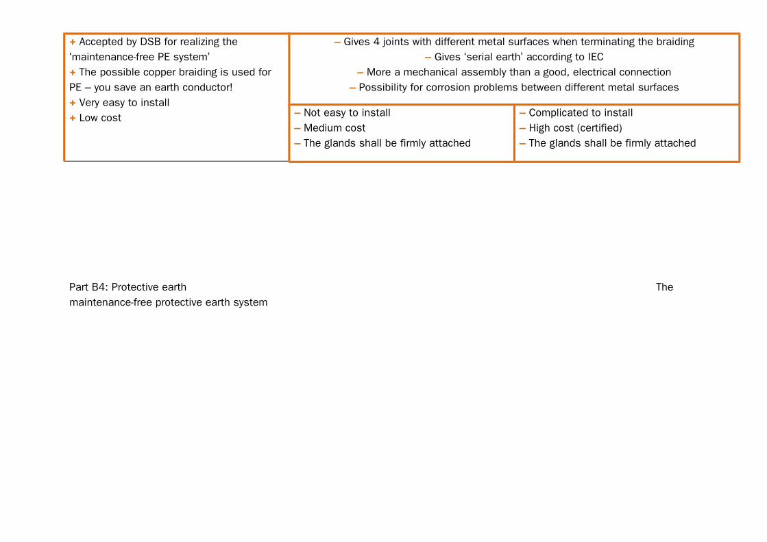
+ Accepted by DSB for realizing the ‘maintenance-free PE system’+ The possible copper braiding is used for PE – you save an earth conductor!+ Very easy to install+ Low cost
– Gives 4 joints with different metal surfaces when terminating the braiding– Gives ‘serial earth’ according to IEC
– More a mechanical assembly than a good, electrical connection– Possibility for corrosion problems between different metal surfaces
– Not easy to install– Medium cost– The glands shall be firmly attached
– Complicated to install– High cost (certified)– The glands shall be firmly attached
Part B4: Protective earth The maintenance-free protective earth system

Part B6: Arrangement of earth bus-bar (DB)
A very unpractical location of the earth bar... Not according to IEC requirements
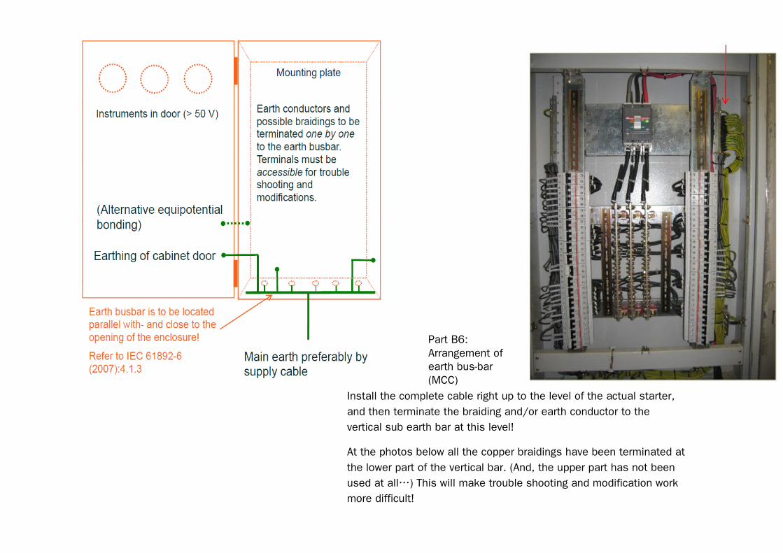
Part B6:Arrangement ofearth bus-bar(MCC)
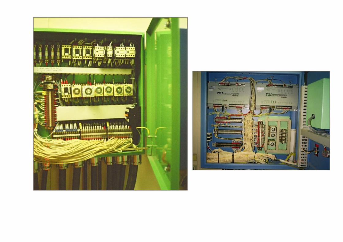
Install the complete cable right up to the level of the actual starter, and then terminate the braiding and/or earth conductor to the vertical sub earth bar at this level!
At the photos below all the copper braidings have been terminated atthe lower part of the vertical bar. (And, the upper part has not been used at all…) This will make trouble shooting and modification work more difficult!
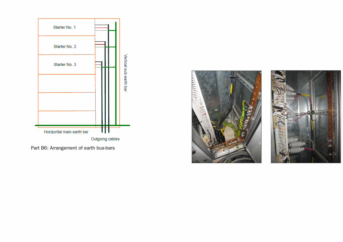
Part B6: Arrangement of earth bus-bars
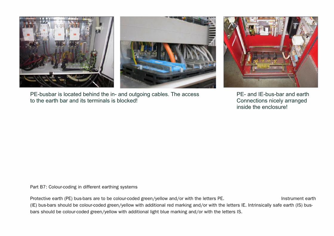
PE-busbar is located behind the in- and outgoing cables. The access PE- and IE-bus-bar and earthto the earth bar and its terminals is blocked! Connections nicely arranged
inside the enclosure!
Part B7: Colour-coding in different earthing systems
Protective earth (PE) bus-bars are to be colour-coded green/yellow and/or with the letters PE. Instrument earth (IE) bus-bars should be colour-coded green/yellow with additional red marking and/or with the letters IE. Intrinsically safe earth (IS) bus-bars should be colour-coded green/yellow with additional light blue marking and/or with the letters IS.

Refer to NORSOK standard Rev. 3 item 12.5.3.
PE: IE: IS:
Yellow / Green Yellow / Green/ Red Yellow / Green/ Light blue
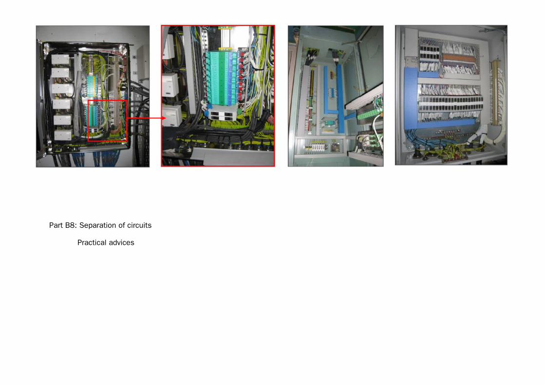
Part B8: Separation of circuits Practical advices
Avoid terminating wires and cables with diferent voltage to the same terminal block – or at least not to the same section of a terminal block
Keep components with different voltage in separate sections on a mounting plate in a cabinet
Take EMC- requirements into consideration
Intrinsically safe circuits need special attention! Refer to IEC 61832-7 (2007):7.9
Part B8: Separation of circuits
Practical advices
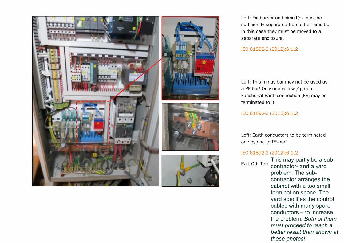
Left: Exi barrier and circuit(s) must be sufficiently separated from other circuits.In this case they must be moved to a separate enclosure.
IEC 61892-2 (2012):6.1.2
Left: This minus-bar may not be used as a PE-bar! Only one yellow / green Functional Earth-connection (FE) may be terminated to it!
IEC 61892-2 (2012):6.1.2
Left: Earth conductors to be terminated one by one to PE-bar!
IEC 61892-2 (2012):6.1.2
Part C9: Termination Problems…This may partly be a sub-contractor- and a yard problem. The sub-contractor arranges the cabinet with a too small termination space. The yard specifies the control cables with many spare conductors – to increase the problem. Both of them must proceed to reach a better result than shown at these photos!

Part B7: Instrument- and intrinsically safe earth