Ds Va Gt1000 Eng
12
1 GT1000 Series Data Sheet DS-VA-GT1000-eng January, 2009 Model GT1024 Brooks ® GT1000 Series Industrial Glass Tube Variable Area Flowmeters Design features • Bra ss or 31 6L SS (1 .44 04) end fit ti ngs • Fla nge d o r thr eaded connectio ns • Hor izontal or vertical connectio ns • Hor izontal end fi tti ngs 36 0 degr ees ro tatable • Sta ndard ac cur acy +2% fu ll scal e / Cl ass 2.5 ac c VDI/VDE Model GT1020 • Epo xy painted cas t al umi num fra me with outstanding environmental resistance • Fluid resistant O-ring desig n allows tube removal without removal from the process piping • Pan el mou nti ng opt ion s avai lab le
Transcript of Ds Va Gt1000 Eng
7/30/2019 Ds Va Gt1000 Eng
http://slidepdf.com/reader/full/ds-va-gt1000-eng 1/12
1
GT1000 Series
Data Sheet
DS-VA-GT1000-eng
January, 2009
Model GT1024
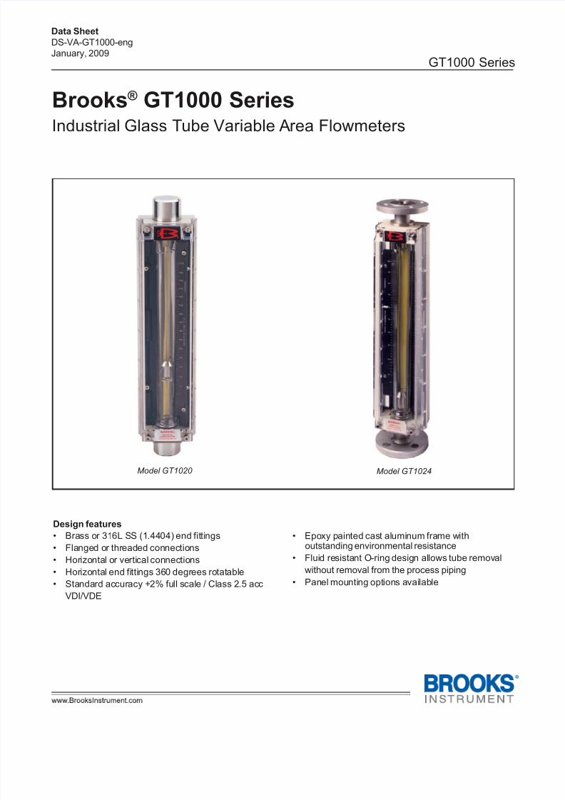
Brooks ® GT1000 SeriesIndustrial Glass Tube Variable Area Flowmeters
Design features
• Brass or 316L SS (1.4404) end fittings
• Flanged or threaded connections
• Horizontal or vertical connections• Horizontal end fittings 360 degrees rotatable
• Standard accuracy +2% full scale / Class 2.5 acc
VDI/VDE
Model GT1020
• Epoxy painted cast aluminum frame withoutstanding environmental resistance
• Fluid resistant O-ring design allows tube removalwithout removal from the process piping
• Panel mounting options available

7/30/2019 Ds Va Gt1000 Eng
http://slidepdf.com/reader/full/ds-va-gt1000-eng 2/12
2
GT1000 Series
Data Sheet
DS-VA-GT1000-eng
January, 2009
Description
The Brooks® GT 1000 combines ruggedness and
simplicity in design to provide a versatile glass tube
flowmeter suitable for a wide range of applications.
The GT 1000 O-ring construction minimizes processdowntime by allowing for convenient in-line removal of
the glass tube for cleaning and maintenance.
Specifications
Capacities and Pressure Drop Tables
Meter sizes 2 - 6, rib guided tubes, spherical float.
Refer to Table 4.
Meter sizes 7 - 13, rib guided tubes, standard float.
Refer to Table 5.
Meter with alarms.
Refer to Table 6.
AccuracyStandard Flow Accuracy: ±2% full scale,
Class 2.5 acc VDI/VDE
Optional Flow Accuracy: ±1% of full scale,
Class 1.6 acc VDI/VDE
Repeatability
<0.5% Full Scale
Pressure Ratings
Refer to Tables 1 & 2 for maximum non-shock
pressure.
Scales
Standard: Single or dual detachable aluminum plate
Nominal Lengths: 127 mm, 200 mm, and 250 mm
Graduations: Choice of direct reading units, millimeter
or percentage of maximum flow with factor tag
Ambient Temperature Limits
33°F to 125°F (1°C to 52°C)
Operating Fluid Temperature Limits (Meter)
Maximum: 250°F (121°C)
Minimum: 33°F(1°C)
Operating Fluid Temperature Limits (Alarms)
Maximum: 250°F (121°C) - Reed Switch
Maximum: 167°F (75°C) - Inductive Switch
Minimum: 33°F(1°C) - Both
Materials of Construction
Metering Tube
Borosilicate glass
Floats (Figure 1)
Sizes 2 and 6: Sapphire, tantalum, glass, Carboloy®,
316 stainless steel
Size 7: Glass, 316 stainless steel or Monel®
Sizes 8-13: 316 stainless steel
Float Stops
Teflon® for sizes 2, 6, 12 and 13
316 stainless steel springs for sizes 7, 8, 9 and 10
Housing
Cast aluminum alloy with Epoxy paint
End Fittings
316/316L stainless steel (1.4404)
brass
WindowPolycarbonate with UV inhibitor
O-rings
Viton® fluoroelastomers
Buna N
Kalrez® (Stainless Steel Body Only)
EPDM (Stainless Steel Body Only)
Hardware
Stainless Steel
Connections
Brass or Stainless Steel Fittings
NPT or BSPT/RC female connections
Stainless Steel Fittings
150 lbs, 300 lbs RF flanges per ANSI B 16.5
PN 40 DIN 2527
Connection Orientation
Vertical or horizontal on inlet and/or outlet
Meter Dimensions
Refer to Figures 2A and 2B
CertificationsMaterial certification to DIN 3.1 or 2.2
Calibration certification to NIST and/or NMI
Declaration of Compliance DIN 2.1
Oxygen cleaning
Positive material identification (PMI)
Positive material identification with carbon
content(PAMI)
Calibration test level
Weight test level

7/30/2019 Ds Va Gt1000 Eng
http://slidepdf.com/reader/full/ds-va-gt1000-eng 3/12
3
GT1000 Series
Data Sheet
DS-VA-GT1000-eng
January, 2009
Inductive Alarms,
Alarm Contacts Meter Sizes 2 and 6
Inductive coils for high and/or low flow alarm may be
mounted to the instrument to create a highly sensitive,
stable and accurate device for signaling high or lowflows or deviations from a controlled flow. The
inductive alarm can only be used in combination with
316 ss or Carboloy ® ball floats. The alarm points may
be adjusted over the entire flowmeter range and be set
so that any two contacts may be made to operate
simultaneously. For hazardous area applications
Brooks can supply an approved Namur power supply/
amplifier/relay unit to obtain an intrinsically safe current
circuit.
Alarm Hysteresis
8mm typical (0.32 in)
Alarm Accessories
Remotely mounted, switch isolator/power supplies are
required for inductive alarms and recommended for
reed switch alarms. One or two single-pole, double-
throw (SPDT) relays are available with either 110 or
220 AC volt units.
Declaration of Compliance DIN 3.1
Pressure test level
Calibration level
NACE MR-01-75
OPTIONAL EQUIPMENT(Alarms, Meter Mounting, Valves)
GT1000 Alarm Contacts Meter Sizes 7 to 13
The Brooks reed switch alarm is a normally open,
latching switch used in conjunction with the GT1000
glass tube flow meter for signaling high and/or low flow
or a deviation from a flow setting.
A magnet embedded and sealed in the float actuates the
alarm switch. The reed switch is mounted adjacent to the
flow tube and is easily adjustable over the entire flow
range of the instrument.
The sealed reed switch consists of a biasing magnet and
hermetically sealed reed switch, which is insulated to
prevent damage from mild shock and normal pipe
vibration. The contact rating of the switch is very low.
An external relay is recommended for secure operation.
Plus the external relay can be configured to operate as a
normally open or normally closed state which provides
totally flexibilty of operation.
Alarm Certifications
Data Reed Switch
Maximum Voltage* 175 Vdc, 124 Vac
Maximum Current* 250 mA
Maximum Contact Rating* 3 Watts
*(Maximum Switch Specifications)
Electrical Classification
Non Incendive:
Maximum Voltage 30 Vdc
Maximum Current 250 mA
Maximum Contact Raing 3 Watts
US and Canada E73889
NI Class I, Div 2, Groups A, B, C and D:
Class II, Groups F and G, T6.
per UL 1604, Third Edition
Environmental rating: Type 4X
Intrinsically Safe:
Entity parameters:
Vmax = Ui = 30 Vdc, Imax = 100 mA, Ci = 0, Li = 0
US and Canada E73889
IS Class I, II, III, Div 1, Groups A, thru G, T6
per UL 913: Sixth Edition
Environmental rating: Type 4X
Table 1 Data 10&15-14-N3 Inductive Coils
Power Supply 8 volt nominal (max. 15.5 Vdc)
Current Consumption Active area clear: > 3 mACurrent Consumption Active area obscured: < 1 mA
Self Inductance 70 µH
Self Capacitance 90 nF
Electrical Classification
Intrinsically safe:
ATEX: PTB99ATEX2128X
Ex II 2 G
EEx ia IIC T6
Enclosure Type: IP67
EMC Directive: EN 60947-5-2 DIN EN 60947-5-6 (Namur)

7/30/2019 Ds Va Gt1000 Eng
http://slidepdf.com/reader/full/ds-va-gt1000-eng 4/12
4
GT1000 Series
Data Sheet
DS-VA-GT1000-eng
January, 2009
Panel Mounting of Meter
Hardware is available for front of panel or flush panel
mounting. Panel mounting hardware is available for
sizes 2 to 10. Panel mounitng is not available for
meters with flange connections or meters with valvesor flow controllers.
Optional NeedleValves / Flow Controllers
For flow rate control, needle valves and/or flow
controllers are externally piped to either the inlet or
outlet connection of the meter. Valves and flow
controllers are available with threaded or flanged
connections. Note, solenoid valves should not be used
because this type of valve can cause pressure shocks
which can damage the glass tube.
Ordering Information and Model Code
Refer to Table 7.
Table 2 Pressure Rating and PED Category - Threaded Connections
Table 3 Pressure Rating and PED Category - Flanged Connections
Maximum Operating Pressure (PSIG / bar) @ Fluid Temperature Listed
Meter Size to 250'F (121'C) PED Category
2 500 / 34.5 SEP
6 450 / 31 SEP
7 300 / 20.7 SEP
8 250 / 17 SEP
9 200 / 13.8 SEP
10 175 / 12.1 SEP12 100 / 6.9 SEE NOTE
13 75 / 5.2 SEE NOTE
Note: Size 12 and 13 do not conform to Pressure Equipment Directive 97/23/EC,
therefore cannot be sold or used in the EU/EFTA
Maximum Operating Pressure (PSIG / bar) @ Fluid Temperature Listed
2 240 / 16.5 500 / 34.5 SEP
6 240 / 16.5 450 / 31 SEP7 240 / 16.5 300 / 20.7 SEP
8 240 / 16.5 250 / 17 SEP
9 200 / 13.8 200 / 13.8 SEP
10 175 / 12.1 175 / 12.1 SEP
12 100 / 6.9 N/A SEE NOTE
13 75 / 5.2 N/A SEE NOTE
Note: Size 12 and 13 do not conform to Pressure Equipment Directive 97/23/EC,
therefore cannot be sold or used in the EU/EFTA
Size ANSI 150# RF to 250°F (121°C) PED Category ANSI 300# RF/DIN PN40
to 250°F (121°C)

7/30/2019 Ds Va Gt1000 Eng
http://slidepdf.com/reader/full/ds-va-gt1000-eng 5/12
5
GT1000 Series
Data Sheet
DS-VA-GT1000-eng
January, 2009
Table 4 Capacity and Pressure Drop Meter Sizes 2 & 6
WATER AIR*
SPHERICAL Flow Rate V. I. C.
TUBE FLOAT cc/min. l/h Inches WC kPa cSt slpm m3/nh Inches WC kPa
SIZE 2 GLASS 0.42 0.025 0.3 0.08 1.0 0.039 0.0021 0.3 0.08
R-2-127-AAAT SAPPHIRE 0.84 0.05 0.4 0.09 1.0 0.06 0.0033 0.4 0.1
316 SS 1.9 0.11 0.7 0.17 1.0 0.11 0.0066 0.8 0.19
CARBOLOY 3.9 0.23 1.1 0.27 1.0 0.2 0.011 1.2 0.3
TANTALUM 4.3 0.26 1.3 0.33 1.0 0.22 0.012 1.4 0.34
SIZE 2 GLASS 1.4 0.086 0.3 0.08 1.0 0.059 0.0033 0.3 0.08
R-2-127-AAT SAPPHIRE 1.9 0.11 0.4 0.09 1.0 0.092 0.0051 0.4 0.1
316 SS 3.0 0.18 0.7 0.18 1.0 0.18 0.01 0.8 0.2
CARBOLOY 5.9 0.35 1.2 0.29 1.0 0.32 0.017 1.3 0.32
TANTALUM 6.6 0.39 1.4 0.34 1.0 0.35 0.019 1.5 0.37
SIZE 2 GLASS 4.2 0.25 0.3 0.08 1.0 0.3 0.016 0.3 0.08
R-2-127-DT SAPPHIRE 8.0 0.48 0.4 0.1 1.0 0.41 0.023 0.4 0.11
316 SS 16 0.98 0.9 0.22 1.0 0.68 0.038 1.0 0.24CARBOLOY 27 1.6 1.5 0.38 1.0 1.0 0.057 1.7 0.42
TANTALUM 29 1.7 1.6 0.41 1.0 1.0 0.061 1.8 0.46
SIZE 2 GLASS 13 0.81 0.4 0.09 1.0 0.69 0.039 0.4 0.1
R-2-127-AT SAPPHIRE 21 1.3 0.5 0.13 1.0 0.93 0.051 0.6 0.14
316 SS 38 2.3 1.1 0.27 1.0 1.4 0.08 1.2 0.3
CARBOLOY 60 3.6 1.9 0.47 1.0 2.0 0.11 2.1 0.52
TANTALUM 64 3.8 2.1 0.52 1.0 2.2 0.12 2.3 0.58
SIZE 2 GLASS 47 2.8 0.6 0.16 1.0 2.0 0.11 0.7 0.18
R-2-127-BT SAPPHIRE 71 4.2 0.8 0.21 1.0 2.7 0.15 0.9 0.23
316 SS 110 7.1 1.8 0.45 1.0 4.1 0.23 2.0 0.51
CARBOLOY 170 10 3.0 0.75 1.0 5.9 0.33 3.3 0.83
TANTALUM 180 11 3.6 0.89 1.0 6.3 0.35 3.9 0.98
SIZE 2 GLASS 69 4.1 0.8 0.21 1.0 3.2 0.18 0.9 0.23
R-2-127-CT SAPPHIRE 100 6.4 1.3 0.32 1.0 4.2 0.23 1.4 0.35
316 SS 180 10 2.5 0.63 1.0 6.3 0.35 2.8 0.7
CARBOLOY 270 16 4.7 1.17 1.0 9.0 0.50 5.2 1.3
TANTALUM 290 17 5.1 1.26 1.0 9.5 0.53 5.6 1.4
SIZE 6 GLASS 160 10 1.8 0.45 1.0 7.3 0.4 2.0 0.5
R-6-127-AT SAPPHIRE 240 14 2.9 0.72 1.0 9.4 0.52 3.2 0.8
316 SS 410 24 6.1 1.53 1.0 14 0.78 6.8 1.7
CARBOLOY 610 36 10.5 2.61 1.0 19 1.1 11.6 2.9
TANTALUM 650 39 11.2 2.80 1.0 20 1.1 12.4 3.1
SIZE 6 GLASS 450 27 9.4 2.34 1.0 19 1.0 10.4 2.6
R-6-127-BT SAPPHIRE 660 40 14.9 3.7 1.0 24 1.3 16.5 4.1
316 SS 1000 65 30.1 7.5 1.0 35 1.9 33.3 8.3
CARBOLOY 1500 95 57.8 14.4 1.0 49 2.7 64.2 16
TANTALUM 1600 100 82.3 20.5 1.0 52 2.9 92.3 23
NOTE: 316 SS AND CARBOLOY FLOAT CAPACITIES LISTED ABOVE CAN BE USED TO SIZE METERS WITH OPTIONAL
INDUCTANCE-TYPE ALARMS
(*) Air flow rates in standard units are at 70'F and 14.7 PSIA, air flow rates in normal units are at 1.013 bar & 20'C
Pressure Drop Pressure DropFlow Rate
7/30/2019 Ds Va Gt1000 Eng
http://slidepdf.com/reader/full/ds-va-gt1000-eng 6/12
6
GT1000 Series
Data Sheet
DS-VA-GT1000-eng
January, 2009
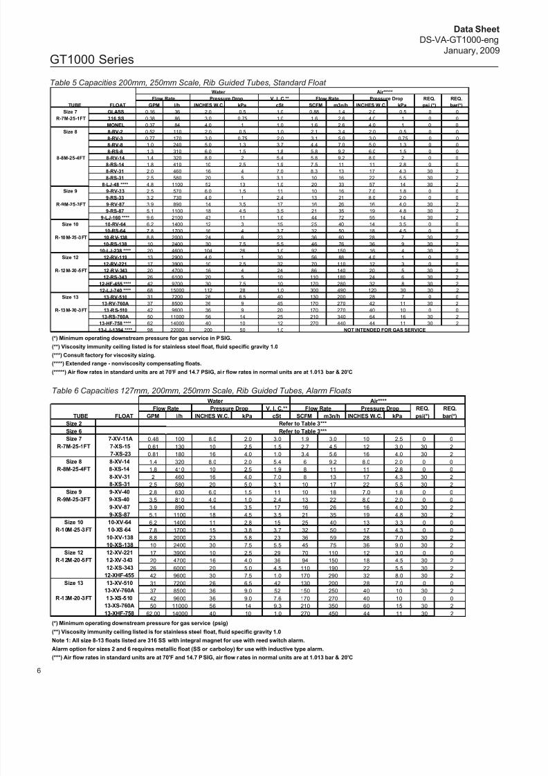
Table 6 Capacities 127mm, 200mm, 250mm Scale, Rib Guided Tubes, Alarm Floats
Table 5 Capacities 200mm, 250mm Scale, Rib Guided Tubes, Standard Float
(*) Minimum operating downstream pressure for gas service in PSIG.
(**) Viscosity immunity ceiling listed is for stainless steel float, fluid specific gravity 1.0
(***) Consult factory for viscosity sizing.
(****) Extended range - nonviscosity compensating floats.
(*****) Air flow rates in standard units are at 70'F and 14.7 PSIG, ai r flow rates in normal units are at 1.013 bar & 20'C
(*) Minimum operating downstream pressure for gas service (psig)
(**) Viscosity immunity ceiling listed is for stainless steel float, fluid specific gravity 1.0
Note 1: All size 8-13 floats listed are 316 SS with integral magnet for use with reed switch alarm.
Alarm option for sizes 2 and 6 requires metallic float (SS or carboloy) for use with inductive type alarm.
(***) Air flow rates in standard units are at 70'F and 14.7 PSIG, air flow rates in normal units are at 1.013 bar & 20'C
Water Air****
Flow Rate Pressure Drop V. I. C.** Flow Rate Pressure Drop REQ. REQ.TUBE FLOAT GPM l/h INCHES W.C. kPa cSt SCFM m3n/h INCHES W.C. kPa psi(*) bar(*)
Size 2 Refer to Table 3***
Size 6 Refer to Table 3***
Size 7 7-XV-11A 0.48 100 8.0 2.0 3.0 1.9 3.0 10 2.5 0 0
R-7M-25-1FT 7-XS-15 0.61 130 10 2.5 1.5 2.7 4.5 12 3.0 30 2
7-XS-23 0.81 180 16 4.0 1.0 3.4 5.6 16 4.0 30 2
Size 8 8-XV-14 1.4 320 8.0 2.0 5.4 6 9.2 8.0 2.0 0 0
R-8M-25-4FT 8-XS-14 1.8 410 10 2.5 1.9 8 11 11 2.8 0 0
8-XV-31 2 460 16 4.0 7.0 8 13 17 4.3 30 2
8-XS-31 2.5 580 20 5.0 3.1 10 17 22 5.5 30 2
Size 9 9-XV-40 2.8 630 6.0 1.5 11 10 18 7.0 1.8 0 0
R-9M-25-3FT 9-XS-40 3.5 810 4.0 1.0 2.4 13 22 8.0 2.0 0 0
9-XV-87 3.9 890 14 3.5 17 16 26 16 4.0 30 2
9-XS-87 5.1 1100 18 4.5 3.5 21 35 19 4.8 30 2
Size 10 10-XV-64 6.2 1400 11 2.8 15 25 40 13 3.3 0 0
R-10M-25-3FT 10-XS-64 7.8 1700 15 3.8 3.7 32 50 17 4.3 0 0
10-XV-138 8.8 2000 23 5.8 23 36 59 28 7.0 30 2
10-XS-138 10 2400 30 7.5 5.5 45 75 36 9.0 30 2
Size 12 12-XV-221 17 3900 10 2.5 29 70 110 12 3.0 0 0
R-12M-20-5FT 12-XV-343 20 4700 16 4.0 36 94 150 18 4.5 30 2
12-XS-343 26 6000 20 5.0 4.5 110 190 22 5.5 30 2
12-XHF-455 42 9600 30 7.5 1.0 170 290 32 8.0 30 2
Size 13 13-XV-510 31 7200 26 6.5 42 130 200 28 7.0 0 0
13-XV-760A 37 8500 36 9.0 52 150 250 40 10 30 2
R-13M-20-3FT 13-XS-510 42 9600 36 9.0 7.6 170 270 40 10 0 0
13-XS-760A 50 11000 56 14 9.3 210 350 60 15 30 2
13-XHF-758 62.00 14000 40 10 1.0 270 450 44 11 30 2
Water Air*****
Flow Rate Pressure Drop V. I. C.** Flow Rate Pressure Drop REQ. REQ.
TUBE FLOAT GPM l/h INCHES W.C. kPa cSt SCFM m3n/h INCHES W.C. kPa psi (*) bar(*)
Size 7 GLASS 0.16 36 2.0 0.5 1.0 0.88 1.4 2.0 0.5 0 0
R-7M-25-1FT 316 SS 0.38 86 3.0 0.75 1.0 1.6 2.6 4.0 1 0 0
MONEL 0.37 84 4.0 1 1.0 1.6 2.6 4.0 1 0 0
Size 8 8-RV-2 0.52 110 2.0 0.5 1.0 2.1 3.4 2.0 0.5 0 0
8-RV-3 0.77 170 3.0 0.75 2.0 3.1 5.0 3.0 0.75 0 0
8-RV-8 1.0 240 5.0 1.3 3.7 4.4 7.0 5.0 1.3 0 0
8-RS-8 1.3 310 6.0 1.5 1.8 5.8 9.2 6.0 1.5 0 0
8-8M-25-4FT 8-RV-14 1.4 320 8.0 2 5.4 5.8 9.2 8.0 2 0 0
8-RS-14 1.8 410 10 2.5 1.9 7.5 11 11 2.8 0 0
8-RV-31 2.0 460 16 4 7.0 8.3 13 17 4.3 30 2
8-RS-31 2.5 580 20 5 3.1 10 16 22 5.5 30 2
8-LJ-48 **** 4.8 1100 52 13 1.0 20 33 57 14 30 2
Size 9 9-RV-33 2.5 570 6.0 1.5 11 10 16 7.0 1.8 0 0
9-RS-33 3.2 730 4.0 1 2.4 13 21 8.0 2.0 0 0
R-9M-25-3FT 9-RV-87 3.9 890 14 3.5 17 16 26 16 4.0 30 2
9-RS-87 5.1 1100 18 4.5 3.5 21 35 19 4.8 30 2
9-LJ-160 **** 9.6 2100 43 11 1.0 44 72 55 14 30 2
Size 10 10-RV-64 6.2 1400 12 3 15 25 40 14 3.5 0 0
10-RS-64 7.8 1700 16 4 3.7 32 50 18 4.5 0 0
R-10M-25-3FT 10-RV-138 8.8 2000 24 6 23 36 60 28 7 30 2
10-RS-138 10 2400 30 7.5 5.5 46 76 36 9 30 2
10-LJ-238 **** 20 4600 104 26 1.0 92 150 16 4 30 2
Size 12 12-RV-119 13 2900 4.0 1 30 56 88 4.0 1 0 0
12-RV-221 17 3900 10 2.5 32 70 110 12 3 0 0
R-12M-20-5FT 12-RV-343 20 4700 16 4 24 86 140 20 5 30 212-RS-343 26 6100 20 5 10 110 180 24 6 30 2
12-HF-455 **** 42 9700 30 7.5 10 170 280 32 8 30 2
12-LJ-740 **** 68 15000 112 28 1.0 300 490 120 30 30 2
Size 13 13-RV-510 31 7200 26 6.5 40 130 200 28 7 0 0
13-RV-760A 37 8500 36 9 45 170 270 42 11 30 2
R-13M-20-3FT 13-RS-510 42 9600 36 9 20 170 270 40 10 0 0
13-RS-760A 50 11000 56 14 25 210 340 64 16 30 2
13-HF-758 **** 62 14000 40 10 12 270 440 44 11 30 2
13-LJ-1394 **** 98 22000 200 50 1.0 NOT INTENDED FOR GAS SERVICE
7/30/2019 Ds Va Gt1000 Eng
http://slidepdf.com/reader/full/ds-va-gt1000-eng 7/12
7
GT1000 Series
Data Sheet
DS-VA-GT1000-eng
January, 2009
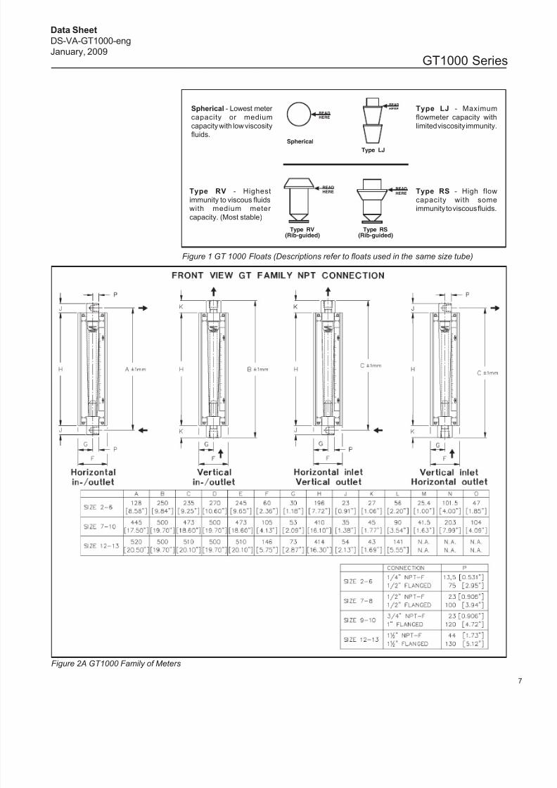
Spherical
Type RS(Rib-guided)
Type RV(Rib-guided)
READHERE
Type LJ
READ
HERE
READHERE
READ
HERESpherical - Lowest meter
capacity or medium
capacity with low viscosity
fluids.
Type LJ - Maximum
flowmeter capacity with
limited viscosity immunity.
Type RS - High flow
capacity with some
immunity to viscous fluids.
Type RV - Highest
immunity to viscous fluids
with medium meter
capacity. (Most stable)
Figure 1 GT 1000 Floats (Descriptions refer to floats used in the same size tube)
Figure 2A GT1000 Family of Meters

7/30/2019 Ds Va Gt1000 Eng
http://slidepdf.com/reader/full/ds-va-gt1000-eng 8/12
8
GT1000 Series
Data Sheet
DS-VA-GT1000-eng
January, 2009
Figure 2B GT 1000 Family of Meters
GT FAMILY - ALARM OPTIONS
7/30/2019 Ds Va Gt1000 Eng
http://slidepdf.com/reader/full/ds-va-gt1000-eng 9/12
9
GT1000 Series
Data Sheet
DS-VA-GT1000-eng
January, 2009
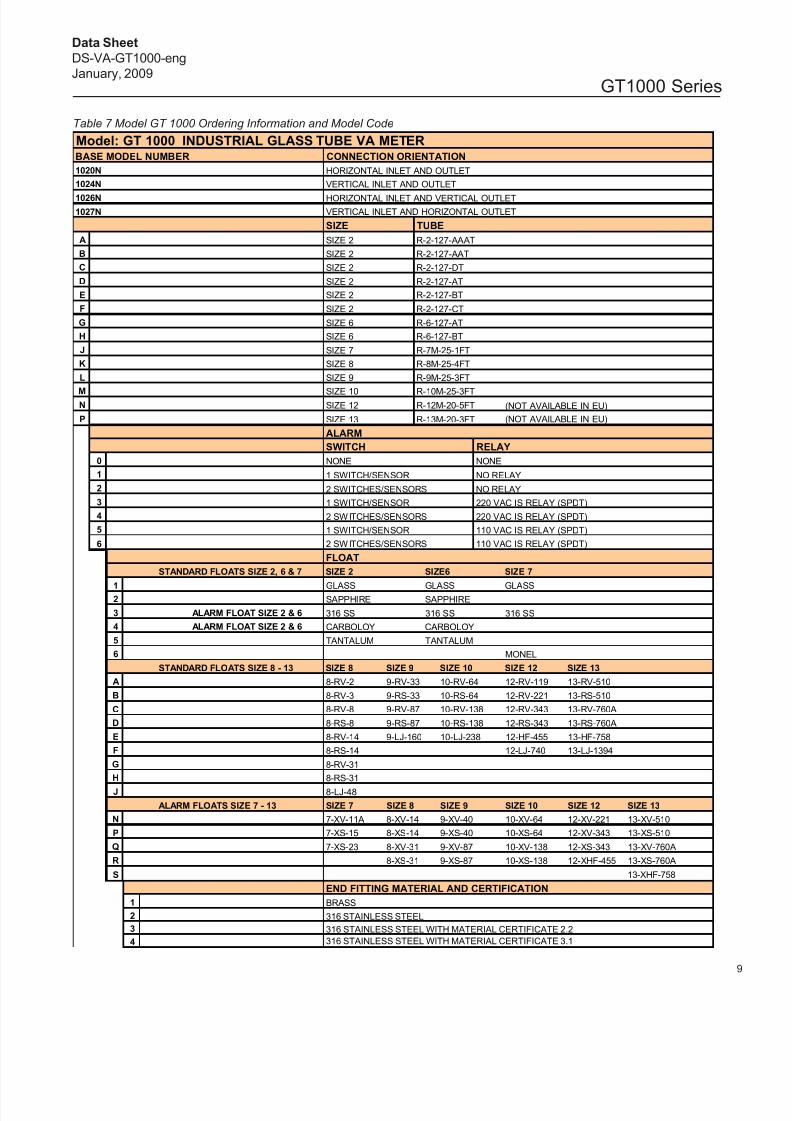
Table 7 Model GT 1000 Ordering Information and Model Code
Model: GT 1000 INDUSTRIAL GLASS TUBE VA METERBASE MODEL NUMBER CONNECTION ORIENTATION
1020N HORIZONTAL INLET AND OUTLET
1024N VERTICAL INLET AND OUTLET
1026N HORIZONTAL INLET AND VERTICAL OUTLET
1027N VERTICAL INLET AND HORIZONTAL OUTLET
SIZE TUBE
A SIZE 2 R-2-127-AAAT
B SIZE 2 R-2-127-AAT
C SIZE 2 R-2-127-DT
D SIZE 2 R-2-127-AT
E SIZE 2 R-2-127-BT
F SIZE 2 R-2-127-CT
G SIZE 6 R-6-127-AT
H SIZE 6 R-6-127-BT
J SIZE 7 R-7M-25-1FT
K SIZE 8 R-8M-25-4FT
L SIZE 9 R-9M-25-3FT
M SIZE 10 R-10M-25-3FTN SIZE 12 R-12M-20-5FT (NOT AVAILABLE IN EU)
P SIZE 13 R-13M-20-3FT (NOT AVAILABLE IN EU)
ALARM
SWITCH RELAY
0 NONE NONE
1 1 SWITCH/SENSOR NO RELAY
2 2 SWITCHES/SENSORS NO RELAY
3 1 SWITCH/SENSOR 220 VAC IS RELAY (SPDT)
4 2 SWITCHES/SENSORS 220 VAC IS RELAY (SPDT)
5 1 SWITCH/SENSOR 110 VAC IS RELAY (SPDT)
6 2 SWITCHES/SENSORS 110 VAC IS RELAY (SPDT)
FLOAT
STANDARD FLOATS SIZE 2, 6 & 7 SIZE 2 SIZE6 SIZE 7
1 GLASS GLASS GLASS2 SAPPHIRE SAPPHIRE
3 ALARM FLOAT SIZE 2 & 6 316 SS 316 SS 316 SS
4 ALARM FLOAT SIZE 2 & 6 CARBOLOY CARBOLOY
5 TANTALUM TANTALUM
6 MONEL
STANDARD FLOATS SIZE 8 - 13 SIZE 8 SIZE 9 SIZE 10 SIZE 12 SIZE 13
A 8-RV-2 9-RV-33 10-RV-64 12-RV-119 13-RV-510
B 8-RV-3 9-RS-33 10-RS-64 12-RV-221 13-RS-510
C 8-RV-8 9-RV-87 10-RV-138 12-RV-343 13-RV-760A
D 8-RS-8 9-RS-87 10-RS-138 12-RS-343 13-RS-760A
E 8-RV-14 9-LJ-160 10-LJ-238 12-HF-455 13-HF-758
F 8-RS-14 12-LJ-740 13-LJ-1394
G 8-RV-31
H 8-RS-31
J 8-LJ-48
ALARM FLOATS SIZE 7 - 13 SIZE 7 SIZE 8 SIZE 9 SIZE 10 SIZE 12 SIZE 13
N 7-XV-11A 8-XV-14 9-XV-40 10-XV-64 12-XV-221 13-XV-510
P 7-XS-15 8-XS-14 9-XS-40 10-XS-64 12-XV-343 13-XS-510
Q 7-XS-23 8-XV-31 9-XV-87 10-XV-138 12-XS-343 13-XV-760A
R 8-XS-31 9-XS-87 10-XS-138 12-XHF-455 13-XS-760A
S 13-XHF-758
END FITTING MATERIAL AND CERTIFICATION
1 BRASS
2 316 STAINLESS STEEL
3 316 STAINLESS STEEL WITH MATERIAL CERTIFICATE 2.2
4 316 STAINLESS STEEL WITH MATERIAL CERTIFICATE 3.1
7/30/2019 Ds Va Gt1000 Eng
http://slidepdf.com/reader/full/ds-va-gt1000-eng 10/12
10
GT1000 Series
Data Sheet
DS-VA-GT1000-eng
January, 2009
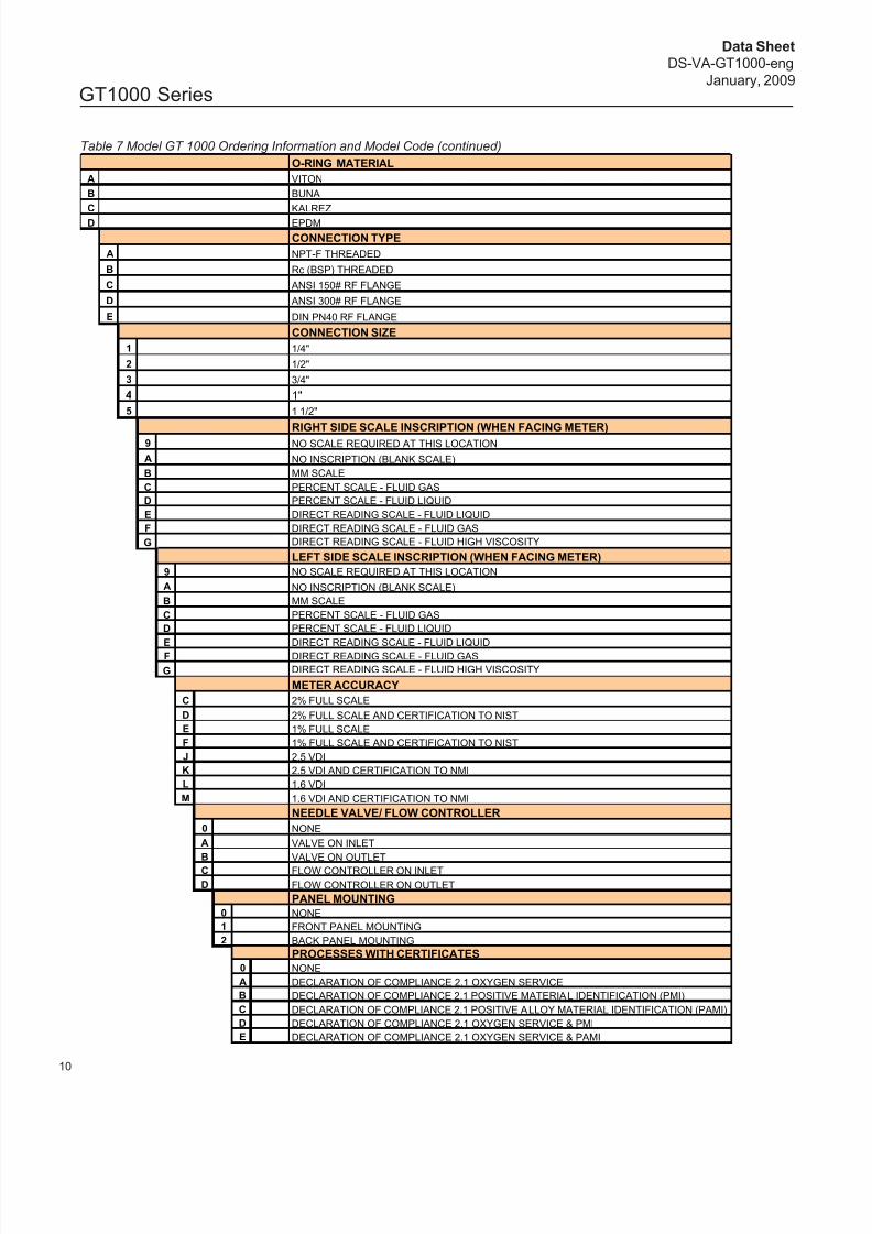
Table 7 Model GT 1000 Ordering Information and Model Code (continued)
O-RING MATERIAL
A VITON
B BUNA
C KALREZ
D EPDM
CONNECTION TYPE
A NPT-F THREADED
B Rc (BSP) THREADED
C ANSI 150# RF FLANGE
D ANSI 300# RF FLANGE
E DIN PN40 RF FLANGE
CONNECTION SIZE
1 1/4"
2 1/2"
3 3/4"
4 1"
5 1 1/2"
RIGHT SIDE SCALE INSCRIPTION (WHEN FACING METER)9 NO SCALE REQUIRED AT THIS LOCATION
A NO INSCRIPTION (BLANK SCALE)
B MM SCALE
C PERCENT SCALE - FLUID GAS
D PERCENT SCALE - FLUID LIQUID
E DIRECT READING SCALE - FLUID LIQUID
F DIRECT READING SCALE - FLUID GAS
G DIRECT READING SCALE - FLUID HIGH VISCOSITY
LEFT SIDE SCALE INSCRIPTION (WHEN FACING METER)
9 NO SCALE REQUIRED AT THIS LOCATION
A NO INSCRIPTION (BLANK SCALE)
B MM SCALE
C PERCENT SCALE - FLUID GAS
D PERCENT SCALE - FLUID LIQUID
E DIRECT READING SCALE - FLUID LIQUID
F DIRECT READING SCALE - FLUID GAS
G DIRECT READING SCALE - FLUID HIGH VISCOSITY
METER ACCURACY
C 2% FULL SCALE
D 2% FULL SCALE AND CERTIFICATION TO NIST
E 1% FULL SCALE
F 1% FULL SCALE AND CERTIFICATION TO NIST
J 2.5 VDI
K 2.5 VDI AND CERTIFICATION TO NMI
L 1.6 VDI
M 1.6 VDI AND CERTIFICATION TO NMI
NEEDLE VALVE/ FLOW CONTROLLER
0 NONE
A VALVE ON INLET
B VALVE ON OUTLET
C FLOW CONTROLLER ON INLET
D FLOW CONTROLLER ON OUTLET
PANEL MOUNTING
0 NONE
1 FRONT PANEL MOUNTING
2 BACK PANEL MOUNTING
PROCESSES WITH CERTIFICATES
0 NONE
A DECLARATION OF COMPLIANCE 2.1 OXYGEN SERVICE
B DECLARATION OF COMPLIANCE 2.1 POSITIVE MATERIAL IDENTIFICATION (PMI)
C DECLARATION OF COMPLIANCE 2.1 POSITIVE ALLOY MATERIAL IDENTIFICATION (PAMI)
D DECLARATION OF COMPLIANCE 2.1 OXYGEN SERVICE & PMI
E DECLARATION OF COMPLIANCE 2.1 OXYGEN SERVICE & PAMI

7/30/2019 Ds Va Gt1000 Eng
http://slidepdf.com/reader/full/ds-va-gt1000-eng 11/12
11
GT1000 Series
Data Sheet
DS-VA-GT1000-eng
January, 2009
Example: GTAK0A2AA3B9C01011
NOTE: INDUCTIVE ALARMS SIZE 2 AND 6 REQUIRE RELAY FOR PROPER OPERATION
Table 7 Model GT 1000 Ordering Information and Model Code (continued)
APPROXIMATE WEIGHTS (ALL UNITS IN POUNDS / KILOGRAMS)
NPT CONNECTIONS FLANGED CONNECTIONS
METER SIZE SHIPPING WEIGHT SHIPPING WEIGHT
2 TO 6 7 / 3.2 10 / 4.5
7 AND 8 12 / 5.5 13 / 5.9
9 18 / 6.2 20 / 9
10 25 / 11.4 29 / 13.2
12 39 / 17.7 49 / 22.3
13 40 / 18.2 52 / 23.6
ADDITIONAL CERTIFICATE REQUIREMENTS
0 NONE
A DECLARATION OF COMPLIANCE 2.1
B DECLARATION OF COMPLIANCE 2.1 CALIBRATION TEST
C DECLARATION OF COMPLIANCE 2.1 PRESSURE TESTD DECLARATION OF COMPLIANCE 2.1 WEIGHT TEST
E PRESSURE INSPECTION TEST CERTIFICATE 3.1
F CALIBRATION INSPECTION TEST CERTIFICATE 3.1
G DECLARATION OF COMPLIANCE 2.1 NACE MR-01-75
H HAZARDOUS LOCATION CERTIFICATE
9 TWO OR MORE CERTIFICATES FROM ABOVE LIST
OEM1 STANDARD
2 NO BROOKS IDENTIFICATION
7/30/2019 Ds Va Gt1000 Eng
http://slidepdf.com/reader/full/ds-va-gt1000-eng 12/12
12
GT1000 Series
Data Sheet
DS-VA-GT1000-eng
January, 2009
TRADEMARKS
Brooks ........................................................... Brooks Instrument, LLC
Carboloy.............................................................. General Electric Co.
Kalrez ...........................................................DuPont Dow Elastomers
Monel ................................................... Inco Alloys International, Inc.
Teflon ................................................ E.I. DuPont de Nemours & Co.
Viton ...............................................DuPont Performance Elastomers
BROOKS SERVICE AND SUPPORT
Brooks is committed to assuring all of our customers receive the ideal flow solution for their application, alongwith outstanding service and support to back it up. We operate first class repair facilities located around the worldto provide rapid response and support. Each location utilizes primary standard calibration equipment to ensure
accuracy and reliability for repairs and recalibration. The primary standard calibration equipment to calibrate our flow products is certified by our local Weights and Measures Authorities and traceable to the relevant InternationalStandards.
Visit www.BrooksInstrument.com to locate the service location nearest to you.
START-UP SERVICE AND IN-SITU CALIBRATION
Brooks Instrument can provide start-up service prior to operation when required. For some process applications,where ISO-9001 Quality Certification is important, it is mandatory to verify and/or (re)calibrate the productsperiodically. In many cases this service can be provided under in-situ conditions, and the results will be traceable tothe relevant international quality standards.
CUSTOMER SEMINARS AND TRAINING
Brooks Instrument can provide customer seminars and dedicated training to engineers, end users andmaintenance persons. Please contact your nearest sales representative for more details.
HELP DESK
In case you need technical assistance:
Americas 1 888 554 FLOW
Europe +31 (0) 318 549 290
Asia +81 (0) 3 5633 7100
Due to Brooks Instrument's commitment to continuous improvement of our products, all specifications are subject to change
without notice.