
DS Accessories GB - · PDF fileDIMENSIONS (TF) Type d H i1 i2 r1 r2 s WEIGHT kg TF 3 1”...
14
FPZ S.p.A. Via F.lli Cervi 16, 20863 Concorezzo (MB), ITALY Tel. +39 039.69.09.811 [email protected] www.fpz.com BLOWERS ACCESSORIES EU VERSION ACCESSORIES FOR LATERAL CHANNEL BLOWERS-EXHAUSTERS Data sheet
Transcript of DS Accessories GB - · PDF fileDIMENSIONS (TF) Type d H i1 i2 r1 r2 s WEIGHT kg TF 3 1”...
F PZ S.p . A . Via F . l l i C er v i 1 6, 20 8 63 Co nc or ez zo ( MB ) , ITA LY Te l . + 3 9 0 39. 69.0 9.8 1 1 i nf o @f pz .co m ww w.f p z . com
BLOWERS ACCESSORIES
EU VERSION
AC
CE
SS
OR
IES
FO
R L
AT
ER
AL
CH
AN
NE
L B
LOW
ER
S-E
XH
AU
ST
ER
S
Dat
a sh
eet
BLOWERS ACCESSORIES
Dimensions in mm - FOR REFERENCE ONLY pag. 2
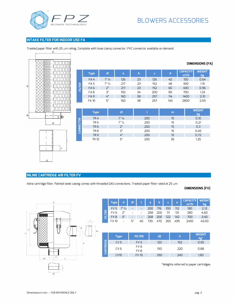
INTAKE FILTER FOR INDOOR USE FA
Treated paper filter with 25 µm rating. Complete with hose clamp connector. PVC connector available on demand.
DIMENSIONS (FA)
INLINE CARTRIDGE AIR FILTER FV
Inline cartridge filter. Painted steel casing comes with threaded GAS connections. Treated paper filter rated at 25 µm
DIMENSIONS (FV)
*Weights referred to paper cartridges
FIL
TE
R
Type d1 a b c d CAPACITY
m3/h WEIGHT
kg
FA 4 1” ¼ 126 23 126 42 100 0,64
FA 5 1” ½ 217 23 152 48 300 1,15
FA 6 2” 217 23 152 60 400 0,96
FA 8 3” 150 34 200 89 700 1,33
FA 9 4” 160 38 257 114 1400 2,10
FA 10 5” 160 38 257 140 2800 2,59
CO
NN
EC
TO
R
Type d1 l m WEIGHT
kg
TR 4 1” ¼ 200 15 0,10
TR 5 1” ½ 200 15 0,21
TR 6 2” 200 15 0,3
TR 8 3” 200 15 0,45
TR 9 4” 200 15 0,72
TR 10 5” 200 35 1,25
F
ILT
ER
Type d d1 l a b c e CAPACITY
m3/h WEIGHT
kg
FV 5 1” ½ - - 200 176 100 112 180 2,12
FV 6 2” - - 258 200 111 131 280 4,60
FV 8 3” - - 268 200 122 142 700 3,40
FV 10 - 5” 40 730 470 265 495 2450 43,00
CA
RT
RID
GE
Type FILTER d2 h WEIGHT
kg*
CV 5 FV 5 120 152 0,55
CV 6 FV 6
150 220 0,88 FV 8
CV10 FV 10 250 240 1,60

BLOWERS ACCESSORIES
Dimensions in mm - FOR REFERENCE ONLY pag. 3
CARTRIDGE INTLET FILTER FL Cartridge filter complete with painted steel casing to protect the cartridge from atmospherics conditions. Treated paper cartridge with 25 µm rating. Complete with hose clamp and PVC connectors.
Options • Screen in stainless steel • Filtrating element in polyester with filtration rate G • CA manifolds or MP sleeves can also be used for easy FA/FL filter installation. • Treated paper cartridge with filtration rate G (25 µm)
DIMENSIONS (FL)
CO
NN
EC
TO
R
Type d2 l m WEIGHT*
kg
TR 1 ½” 100 15 0,02
TR 2 ¾” 130 15 0,04
TR 3 1” 130 15 0,06
TR 4 1” ¼ 200 15 0,13
TR 5 1” ½ 200 15 0,45
TR 6 2” 200 15 0,81
TR 8 3” 200 15 1,26
TR 9 4” 200 15 1,86
TR 10 5” 200 35 1,50
*Weights referred to paper cartridges
FIL
TE
R
Type a d H s CAPACITY
m3/h WEIGHT
kg
FL 1 75 21 62 23 25 0,19
FL 2 150 27 105 23 85 0,62
FL 3 150 33 105 23 85 0,50
FL 4 150 42 105 23 85 0,85
FL 5 180 48 155 23 250 1,50
FL 6 230 60 155 23 400 1,90
FL 8 280 89 180 35 700 3,60
FL 9 410 114 330 35 1400 7,80
FL 10 410 140 330 35 2800 6,73
CA
RT
RID
GE
Type FILTER a1 d1 h1 WEIGHT
kg
CF 1 FL 1 55 25 50 0,04
CF 4
FL 2
108 55 83 0,20 FL 3
FL 4
CF 5 FL 5 147 80 135 0,45
CF 6 FL 6 176 80 135 0,62
CF 8 FL 8 225 100 150 1,07
CF 9 FL 9
300 215 300 1,78 FL 10
BLOWERS ACCESSORIES
Dimensions in mm - FOR REFERENCE ONLY pag. 4
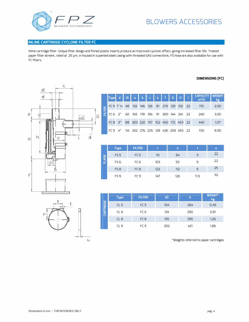
INLINE CARTRIDGE CYCLONE FILTER FC
Inline cartridge filter. Unique filter design and finned plastic inserts produce an improved cyclonic effect, giving increased filter life. Treated
paper filter elment, rated at 25 µm, in housed in a painted steel casing with threaded GAS connections. FS hose are also available for use with
FC filters.
DIMENSIONS (FC)
*Weights referred to paper cartridges
FIL
TE
R
Type d d1 a b c e f G H i CAPACITY
m3/h WEIGHT
kg
FC 5 1” ½ 48 132 146 126 81 270 129 312 22 170 2,50
FC 6 2” 60 165 178 156 91 300 144 341 22 240 3,50
FC 8 3” 88 203 220 157 102 400 172 453 22 440 1,07
FC 9 4” 114 262 276 225 128 430 208 493 22 730 8,90
FLA
SK
Type FILTER r s t u
FS 5 FC 5 70 84 9 22
FS 6 FC 6 103 93 9 22
FS 8 FC 8 122 112 9 25
FS 9 FC 9 147 126 11.5 32
CA
RT
RID
GE
Type FILTER d2 h WEIGHT*
kg
CL 5 FC 5 104 264 0,45
CL 6 FC 6 134 290 0,81
CL 8 FC 8 155 395 1,26
CL 9 FC 9 202 421 1,86
BLOWERS ACCESSORIES
Dimensions in mm - FOR REFERENCE ONLY pag. 5
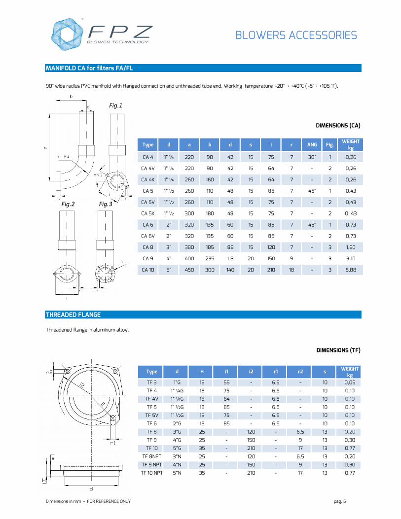
MANIFOLD CA for filters FA/FL
90° wide radius PVC manifold with flanged connection and unthreaded tube end. Working temperature -20° ÷ +40°C ( -5° ÷ +105 °F).
DIMENSIONS (CA)
THREADED FLANGE
Threadened flange in aluminum alloy.
DIMENSIONS (TF)
Type d H i1 i2 r1 r2 s WEIGHT kg
TF 3 1”G 18 55 - 6.5 - 10 0,05
TF 4 1” ¼G 18 75 - 6.5 - 10 0,10
TF 4V 1” ¼G 18 64 - 6.5 - 10 0,10
TF 5 1” ½G 18 85 - 6.5 - 10 0,10
TF 5V 1” ½G 18 75 - 6.5 - 10 0,10
TF 6 2”G 18 85 - 6.5 - 10 0,10
TF 8 3”G 25 - 120 - 6.5 13 O,20
TF 9 4”G 25 - 150 - 9 13 0,30
TF 10 5”G 35 - 210 - 17 13 0,77
TF 8NPT 3”N 25 - 120 - 6.5 13 O,20
TF 9 NPT 4”N 25 - 150 - 9 13 0,30
TF 10 NPT 5”N 35 - 210 - 17 13 0,77
Type d a b d s i r ANG Fig. WEIGHT
kg
CA 4 1” ¼ 220 90 42 15 75 7 30° 1 0,26
CA 4V 1” ¼ 220 90 42 15 64 7 - 2 0,26
CA 4K 1” ¼ 260 160 42 15 64 7 - 2 0,26
CA 5 1” ½ 260 110 48 15 85 7 45° 1 0,43
CA 5V 1” ½ 260 110 48 15 75 7 - 2 0,43
CA 5K 1” ½ 300 180 48 15 75 7 - 2 0, 43
CA 6 2” 320 135 60 15 85 7 45° 1 0,73
CA 6V 2” 320 135 60 15 85 7 - 2 0,73
CA 8 3” 380 185 88 15 120 7 - 3 1,60
CA 9 4” 400 235 113 20 150 9 - 3 3,10
CA 10 5” 450 300 140 20 210 18 - 3 5,88
Fig.1
Fig.2 Fig.3

BLOWERS ACCESSORIES
Dimensions in mm - FOR REFERENCE ONLY pag. 6
FLANGE VK valve housing vrl
The VK accessory makes it possible to connect VRL valves directly on the cover of the series K blowers:
• SCL K-MS applicable in delivery and intake;
• SCL K-MD applicable only in intake;
• SCL K-TS applicable both in delivery and intake;
• SCL K-TD not applicable.
CHARACTERISTICS
Aluminium alloy flange with threaded connector.
Supplied with installation kit (seal, screws, bolts and spanner).
DIMENSIONS (VK)
Type Dn G a i
VK 5G 1” ½G 1” ½G 30 92
VK 6G 2”G 2”G 50 110
VK 6AG 2”G 2”G 59.5 130
VK 8G 3”G 3”G 43 130
VK 9G 4”G 4”G 46 150
VK 5N 1” ½N 1” ½ N 30 92
VK 6N 2”N 2”N 50 110
VK 6AN 2”N 2”N 59.5 130
VK 8N 3”N 3”N 43 130
VK 9N 4”N 4”N 46 150
Type r s t Fig. WEIGHT kg
VK 5G 6.5 10 10 1 0,09
VK 6G 8.5 12 10 1 0,09
VK 6AG 9 12 11 2 0,09
VK 8G 9 10 11 2 O,09
VK 9G 9 12 11 2 0,40
VK 5N 6.5 10 10 1 0,09
VK 6N 8.5 12 10 1 0,09
VK 6AN 9 12 11 2 0,09
VK 8N 9 10 11 2 O,09
VK 9N 9 12 11 2 0,40
Fig.1
Fig.2
BLOWERS ACCESSORIES
Dimensions in mm - FOR REFERENCE ONLY pag. 7
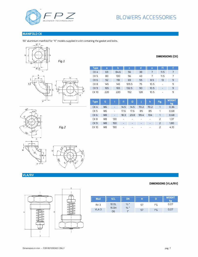
MANIFOLD CK
90° aluminium manifold for “K” models supplied in a kit containing the gasket and bolts.
DIMENSIONS (CK)
Type a b c d e f1 f
CK 4 69 84.6 56 38 7 11.5 7
CK 5 80 100 56 43 7 11.5 7
CK 6 92 118 69 55 8.5 13 9
CK 8 145 145 109.5 75 10.5 - 9
CK 9 165 165 132.5 90 10.5 - 9
CK 10 220 220 192 128 10.5 - 9
Type G i i1 i2 j k Fig. WEIGHT kg
CK 4 M6 - 14.5 14.5 70.2 70.2 1 0,36
CK 5 M6 - 17.6 17.6 85 85 1 0,68
CK 6 M8 - 18.3 23.8 99.4 104 1 0,68
CK 8 M8 130 - - - - 2 1,37
CK 9 M8 150 - - - - 2 1,80
CK 10 M8 190 - - - - 2 4,10
VLA/RV
DIMENSIONS (VLA/RV)
Mod SCL DN H D WEIGHT kg
RV 3 10 DL
15 DH
06
½ “
¾ “
1”
57 1”G 0.07
VLA 3 57 1”G 0,07
Fig.1
Fig.2
BLOWERS ACCESSORIES
Dimensions in mm - FOR REFERENCE ONLY pag. 8
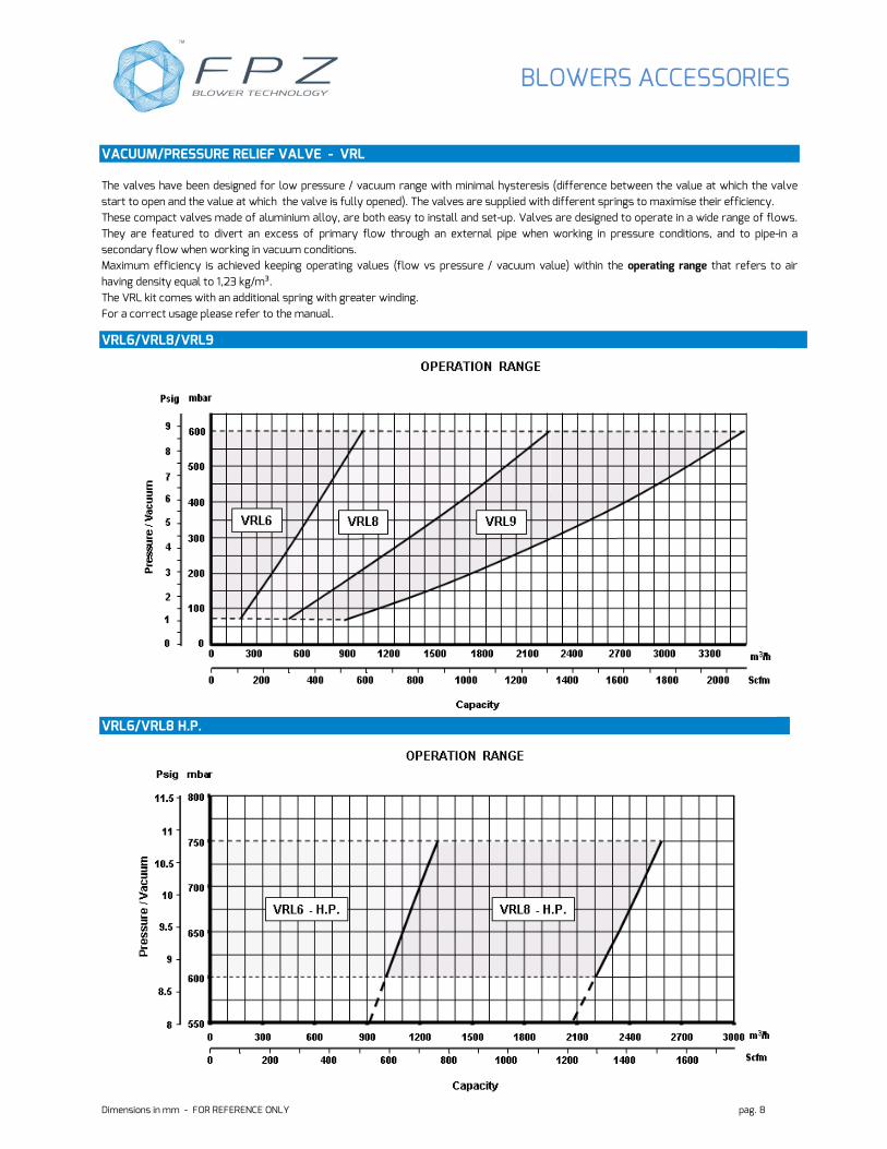
VACUUM/PRESSURE RELIEF VALVE - VRL
The valves have been designed for low pressure / vacuum range with minimal hysteresis (difference between the value at which the valve
start to open and the value at which the valve is fully opened). The valves are supplied with different springs to maximise their efficiency.
These compact valves made of aluminium alloy, are both easy to install and set-up. Valves are designed to operate in a wide range of flows.
They are featured to divert an excess of primary flow through an external pipe when working in pressure conditions, and to pipe-in a
secondary flow when working in vacuum conditions.
Maximum efficiency is achieved keeping operating values (flow vs pressure / vacuum value) within the operating range that refers to air
having density equal to 1,23 kg/m³.
The VRL kit comes with an additional spring with greater winding.
For a correct usage please refer to the manual.
VRL6/VRL8/VRL9
VRL6/VRL8 H.P.

BLOWERS ACCESSORIES
Dimensions in mm - FOR REFERENCE ONLY pag. 9
DIMENSIONS
Flow Diagram 1
Closed Vacuum/pressure relief valve Open Vacuum/pressure relief valve
VA
CU
UM
PR
ES
SU
RE
1 Caution: to read the correct value indicated on the pressure/vacuum gauge, position it between the silencer and the VRL valve.
*See the relevant data sheet
VA
LVE
Mod. DN d a b h Weight
Kg
VRL6 50 G 2” 102 175 12 0.85
VRL8 80 G 3” 135 190 15 1.90
VRL9 100 G 4” 160 206 18 2.60
VA
LVE
Mod. DN d a b h Weight
kg
VRL6 - HP 50 G 2” 102 175 12 0.85
VRL8 - HP 80 G 3” 135 190 15 1.90
BLOWERS ACCESSORIES
Dimensions in mm - FOR REFERENCE ONLY pag. 10
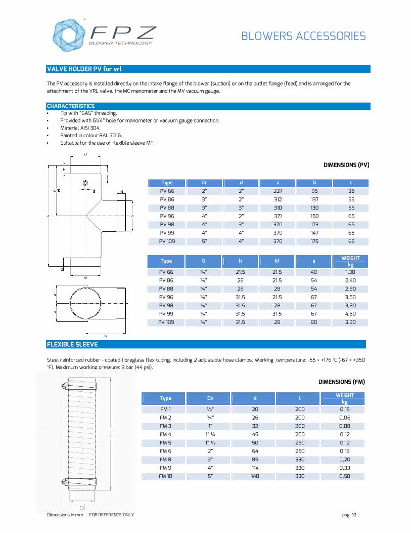
VALVE HOLDER PV for vrl
The PV accessory is installed directly on the intake flange of the blower (suction) or on the outlet flange (feed) and is arranged for the
attachment of the VRL valve, the MC manometer and the MV vacuum gauge.
CHARACTERISTICS • Tip with “GAS” threading.
• Provided with G1/4” hole for manometer or vacuum gauge connection.
• Material AISI 304.
• Painted in colour RAL 7016.
• Suitable for the use of flexible sleeve MF.
DIMENSIONS (PV)
FLEXIBLE SLEEVE
Steel reinforced rubber - coated fibreglass flex tubing, including 2 adjustable hose clamps. Working temperature: -55 ÷ +176 °C (-67 ÷ +350
°F). Maximum working pressure: 3 bar (44 psi).
DIMENSIONS (FM)
Type Dn d l WEIGHT kg
FM 1 ½” 20 200 0,15
FM 2 ¾” 26 200 0,06
FM 3 1” 32 200 0,08
FM 4 1” ¼ 45 200 0,12
FM 5 1” ½ 50 250 0,12
FM 6 2” 64 250 0,18
FM 8 3” 89 330 0,20
FM 9 4” 114 330 0,33
FM 10 5” 140 330 0,50
Type Dn d a b c
PV 66 2” 2” 227 95 35
PV 86 3” 2” 312 137 55
PV 88 3” 3” 310 130 55
PV 96 4” 2” 371 150 65
PV 98 4” 3” 370 173 65
PV 99 4” 4” 370 147 65
PV 109 5” 4” 370 175 65
Type G h h1 s WEIGHT kg
PV 66 ¼” 21.5 21.5 40 1,30
PV 86 ¼” 28 21.5 54 2,40
PV 88 ¼” 28 28 54 2,80
PV 96 ¼” 31.5 21.5 67 3,50
PV 98 ¼” 31.5 28 67 3,80
PV 99 ¼” 31.5 31.5 67 4,60
PV 109 ¼” 31.5 28 80 3,30
BLOWERS ACCESSORIES
Dimensions in mm - FOR REFERENCE ONLY pag. 11
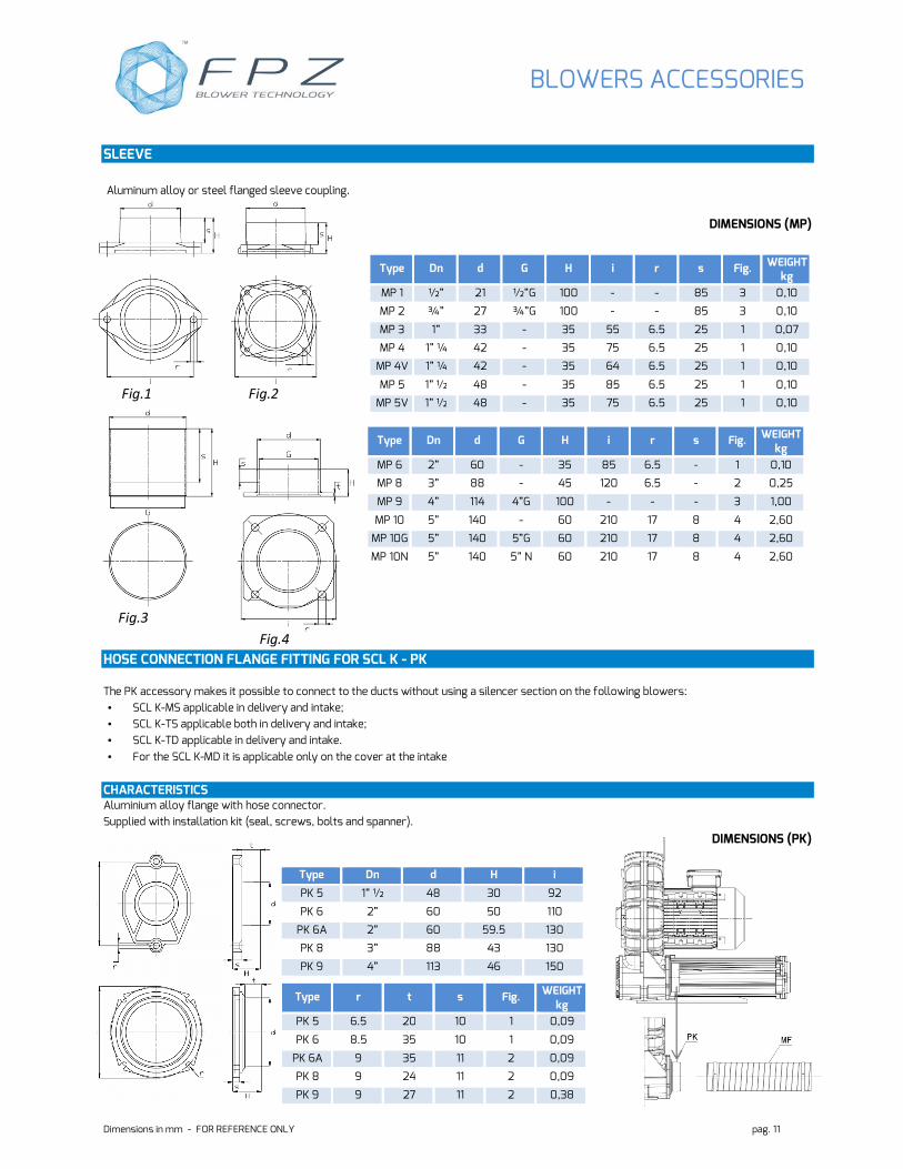
SLEEVE
Aluminum alloy or steel flanged sleeve coupling.
DIMENSIONS (MP)
Type Dn d G H i r s Fig. WEIGHT kg
MP 1 ½” 21 ½”G 100 - - 85 3 0,10
MP 2 ¾” 27 ¾”G 100 - - 85 3 0,10
MP 3 1” 33 - 35 55 6.5 25 1 0,07
MP 4 1” ¼ 42 - 35 75 6.5 25 1 0,10
MP 4V 1” ¼ 42 - 35 64 6.5 25 1 0,10
MP 5 1” ½ 48 - 35 85 6.5 25 1 0,10
MP 5V 1” ½ 48 - 35 75 6.5 25 1 0,10
HOSE CONNECTION FLANGE FITTING FOR SCL K - PK
The PK accessory makes it possible to connect to the ducts without using a silencer section on the following blowers:
• SCL K-MS applicable in delivery and intake;
• SCL K-TS applicable both in delivery and intake;
• SCL K-TD applicable in delivery and intake.
• For the SCL K-MD it is applicable only on the cover at the intake
CHARACTERISTICS Aluminium alloy flange with hose connector.
Supplied with installation kit (seal, screws, bolts and spanner).
DIMENSIONS (PK)
Type Dn d H i
PK 5 1” ½ 48 30 92
PK 6 2” 60 50 110
PK 6A 2” 60 59.5 130
PK 8 3” 88 43 130
PK 9 4” 113 46 150
Type Dn d G H i r s Fig. WEIGHT kg
MP 6 2” 60 - 35 85 6.5 - 1 0,10
MP 8 3” 88 - 45 120 6.5 - 2 0,25
MP 9 4” 114 4”G 100 - - - 3 1,00
MP 10 5” 140 - 60 210 17 8 4 2,60
MP 10G 5” 140 5”G 60 210 17 8 4 2,60
MP 10N 5” 140 5” N 60 210 17 8 4 2,60
Type r t s Fig. WEIGHT kg
PK 5 6.5 20 10 1 0,09
PK 6 8.5 35 10 1 0,09
PK 6A 9 35 11 2 0,09
PK 8 9 24 11 2 0,09
PK 9 9 27 11 2 0,38
Fig.1 Fig.2
Fig.3
Fig.4
BLOWERS ACCESSORIES
Dimensions in mm - FOR REFERENCE ONLY pag. 12
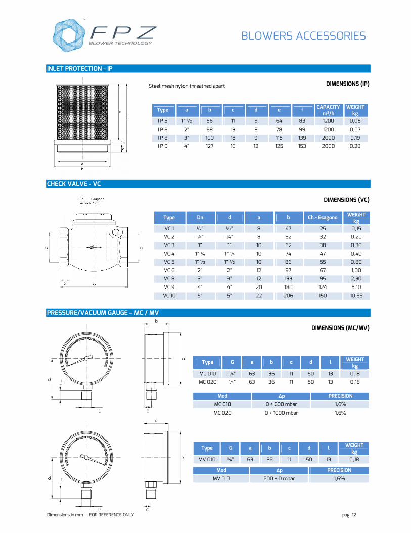
INLET PROTECTION - IP
DIMENSIONS (IP)
CHECK VALVE - VC
DIMENSIONS (VC)
PRESSURE/VACUUM GAUGE – MC / MV
DIMENSIONS (MC/MV)
Type a b c d e f CAPACITY m3/h
WEIGHT kg
I P 5 1” ½ 56 11 8 64 83 1200 0,05
I P 6 2” 68 13 8 78 99 1200 0,07
I P 8 3” 100 15 9 115 139 2000 0,19
I P 9 4” 127 16 12 125 153 2000 0,28
Type Dn d a b Ch.- Esagono WEIGHT kg
VC 1 ½” ½” 8 47 25 0,15
VC 2 ¾” ¾” 8 52 32 0,20
VC 3 1” 1” 10 62 38 0,30
VC 4 1” ¼ 1” ¼ 10 74 47 0,40
VC 5 1” ½ 1” ½ 10 86 55 0,80
VC 6 2” 2” 12 97 67 1,00
VC 8 3” 3” 12 133 95 2,30
VC 9 4” 4” 20 180 124 5,10
VC 10 5” 5” 22 206 150 10,55
Type G a b c d l WEIGHT kg
MC 010 ¼” 63 36 11 50 13 0,18
MC 020 ¼” 63 36 11 50 13 0,18
Mod ∆p PRECISION
MC 010 0 ÷ 600 mbar 1,6%
MC 020 0 ÷ 1000 mbar 1,6%
Type G a b c d l WEIGHT kg
MV 010 ¼” 63 36 11 50 13 0,18
Mod ∆p PRECISION
MV 010 600 ÷ 0 mbar 1,6%
Steel mesh nylon threathed apart
BLOWERS ACCESSORIES
Dimensions in mm - FOR REFERENCE ONLY pag. 13
0
5
10
15
20
250 2000 16000
0
10
20
30
0
5
10
15
20
0
5
10
15
20
25
0
5
10
15
20
250 2000 16000
0
10
20
30
250 2000 16000
0
10
20
30
Hz
Hz
Hz
Hz
dB(A)
dB(A)
dB(A)
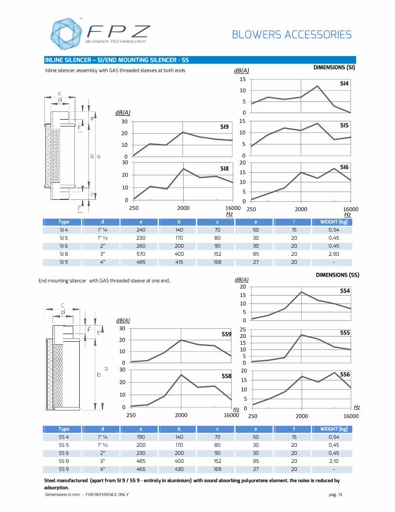
Steel manufactured (apart from SI 9 / SS 9 - entirely in aluminium) with sound absorbing polyuretane element, the noise is reduced by
adsorption.
dB(A)
INLINE SILENCER – SI/END MOUNTING SILENCER - SS DIMENSIONS (SI)
DIMENSIONS (SS)
Type d a b c e f WEIGHT [kg]
SI 4 1” ¼ 240 140 70 50 15 0,54
SI 5 1” ½ 230 170 80 30 20 0,45
SI 6 2” 260 200 90 30 20 0,45
SI 8 3” 570 400 152 85 20 2,90
SI 9 4” 485 415 168 27 20 -
Type d a b c e f WEIGHT [kg]
SS 4 1” ¼ 190 140 70 50 15 0,54
SS 5 1” ½ 200 170 80 30 20 0,45
SS 6 2” 230 200 90 30 20 0,45
SS 8 3” 485 400 152 85 20 2,10
SS 9 4” 465 430 169 27 20 -
0
5
10
15
0
5
10
15
0
10
20
30
250 2000 16000
SI4
SI5
SI6
SI9
SI8
SS4
SS5
SS6
SS9
SS8
Inline silencer assembly with GAS threaded sleeves at both ends
End mounting silencer with GAS threaded sleeve at one end..
BLOWERS ACCESSORIES
maggio ’14
FPZ Espana/Portugal Pral, Barcelona Espana [email protected] HEADQUARTERS
FPZ S.p.A. Concorezzo (MB) Italy [email protected]
FPZ France S.a.r.l. St. Priest France [email protected]
FPZ, Inc Soukville, Wisconsin USA [email protected]
FPZ Austria & Germany Krems Austria [email protected]
FPZ UK Andover, Hampshire United Kingdom [email protected]
FPZ México/LA Zapopan, Jalisco México [email protected]


![g]kfn ;/sf/ /fli6«o ;ts{tf s]Gb| - nvc.gov.np](https://static.fdocuments.us/doc/165x107/621deed6869df322952c3884/gkfn-sf-fli6o-tstf-sgb-nvcgovnp.jpg)

