Drypower 12V smart battery user Guide...•Do not short circuit the 12V batteries. The 12V LiF4...
24
Prepared date Approved date File number S230XLP03 Page 1/24 Version A Please read all contents of this user’s guide prior to use the battery. Drypower Lithium Iron Phosphate 12V Smart Battery User Guide 12V Smart Battery User Guide
Transcript of Drypower 12V smart battery user Guide...•Do not short circuit the 12V batteries. The 12V LiF4...

Prepared date
Approved date File number S230XLP03 Page 1/24Version A
Please read all contents of this user’s guide prior to
use the battery.
Drypower Lithium Iron Phosphate12V Smart Battery
User Guide
12V Smart BatteryUser Guide

Prepared date
Approved date File number S230XLP03 Page 2/24Version A
TABLE OF CONTENTS
1 Contact Information................................................................................................................... 3
2 Safety Information..................................................................................................................... 3
3 Before You Start ....................................................................................................................... 5
4 Installation................................................................................................................................. 6
5 Charging The Batteries ............................................................................................................. 9
6 Discharging The Batteries....................................................................................................... 11
7 Battery performance................................................................................................................ 12
8 Integrated Protection ............................................................................................................ 16
9 Trouble Shooting .................................................................................................................. 17
10 Tips For Optimizing Performance ......................................................................................... 21
11 Maintenance And Storage 21
12 Transportation And Shipping................................................................................................. 22
13 Battery Overheating .............................................................................................................. 22
14 Disposal Of Batteries ............................................................................................................ 23
15 Use In Life Support Applications ........................................................................................... 24
12V Smart BatteryUser Guide

Prepared date
Approved date File number S230XLP03 Page 3/24Version A
1 Contact Information
Head Office:Master Instruments Pty LtdAddress:33-39 Sloane Street, Marrickville NSW Australia 2204Telephone: +61 2 9519 1200Fax: +61 2 9519 4604Website: www.master-instruments.com.auEmail: [email protected]
Western Australia State Office: Victoria State Office: Queensland State Office:
Telephone: +61 8 9302 5444Telephone: +61 3 9872 6422Telephone: +61 7 5546 1676
2 Safety Information
The battery must be used in accordance with the manufacturer’s specifications and guidelines for recommended use. When used properly and in accordance with these instructions, thebattery is a safe, reliable and convenient energy storage solution.
CAUTION: Misuse or abuse of the battery may result in personal injury or fire.
Keep all original packaging. International law dictates that the batteries are shipped under UN 3480, Class 9 rules for hazardous goods/dangerous materials.
Burn Hazard. Abusive operation of the battery (e.g. overcharge, crush, puncture, excessive heat or
moisture) may produce smoke. In such an event, ventilate the area. Extinguish any flames with copious amounts of water, use a carbon dioxide, dry-powder fire
extinguisher, or cover with sand or mud (therefore removing excess oxygen from the flame). DO NOT disassemble, crush, puncture, or incinerate. DO NOT short circuit external contacts. DO NOT expose to temperatures above 50℃(122°F). NEVER charge the battery without charge protection circuitry and equipment approved by
Drypower. Remove all jewelry or other metallic objects during the installation of the battery. Exercise care in handling any charged battery, particularly when placing it inside a container
with metal objects DO NOT throw the battery away in the trash.
12V Smart BatteryUser Guide

Prepared date
Approved date File number S230XLP03 Page 4/24Version A
Dispose of the battery properly in accordance with local regulations. DO NOT connect Drypower 12V smart LiFePO4 battery to other chemistries, lots,
manufacturers, series, impedance or capacity 12V battery.Your battery may contain symbols, defined as follows:
Symbol Definition
Important safety information will follow.
DO NOT dispose of battery in a fire.
RECYCLE! Battery may require recycling in accordance with local laws. Regardless recycling is encouraged. Contact local regulatory authorities for more information. DO NOT include battery with lead acid battery recycling.
DO NOT dispose of battery in the trash.
Shock Hazard - Labels may be located on or inside the equipment to alert people that dangerous voltage may be present.
Burn Hazard - Labels may be located on or inside the equipment to alert people that surface temperatures may be dangerous.
2.1 Internal Protection FeaturesThe battery has several features built-in to protect against the effect of abusive conditions:
12V Smart BatteryUser Guide

Prepared date
Approved date File number S230XLP03 Page 5/24Version A
Drypower Lithium Iron Phosphate technology in every cell provides lithium-ion advantagesof high energy, light weight, and long life without the fear of thermal runaway under abuse conditions.
Built-in PCM can offer over voltage, under voltage, over current and over temperature protection and balancing.
The 12V smart battery can offer communication and fuel gauge indicator which make the battery much more easy to use and maintenance.
3 BEFORE YOU START
3.1 Caution
Please read all the safety information provided in this document prior to installing and/or operating the battery.The Drypower battery should be professionally installed and handled. Please contact Drypowerfor free consultation if you have any questions about the handling, operation and safe use of this battery proceeding further.
CAUTION: Performing any of the following actions will immediately void your warranty on the product and could lead to a potentially dangerous situation. Breaking the lid and exposing the circuit boards and battery assemblies. Punching or otherwise physically damaging the battery casing, circuit boards, battery cells or
any other part of the battery mechanism. Operating the battery in an environment where the temperature is higher than 50℃(122°F).
If you believe that in the course of using the Drypower battery, you will conflict with any of the above listed conditions or any other safety precautions listed in this manual, please DO NOT proceed any further. Contact your place of purchase immediately for guidance and information.
VISUAL INSPECTIONPlease inspect each battery carefully. Report any damage from shipping to Drypower immediately.
SYSTEM CONFIGURATION LIMITSThe smart batteries are UL Recognized as a standalone battery only and has not been evaluated for series and/or parallel configuration. If you need connect them in series/parallel for extended applications, kindly obey the below system configuration limits,
Battery model 12V Smart BatteryMaximum System Voltage 24V (2 pcs in series)Maximum Number of Batteries in Parallel 3 pcs in parallel *
Table 1: System ConfigurationNote: see section 4.6 (page 9) and section 6.1 (page 12)
12V Smart BatteryUser Guide

Prepared date
Approved date File number S230XLP03 Page 6/24Version A
3.2 DefinitionDrypower defines battery components and batteries as follows: Cell – A single LiFePO4 battery representing 3.2V. Cell Block – A group of cells configured in parallel. Battery Pack – A group of batteries in series or in parallel. Hereafter, we will say battery. 12V Smart Battery – Drypower 12.8V LiFePO4 battery with SMbus communication & fuel
gauge indicator.
Figure 1 IFM12-90E3 Figure 2 IFM12-200E3 Figure 3 IFM12-420E3See section 7 (page 13) to know more details of the above batteries.
4 INSTALLATION
IMPORTANT! Remove all jewelry or other metallic objects from your hands and body during the installation of the battery and peripherals. Turn off power to the device prior to installation of the battery.
4.1 Tips
Do not install batteries above heat generating equipment. Ensure that all batteries are at same state of charge prior to connecting together. Contact
your place of purchase for suggestions on how to perform this task. Use flexible insulated copper cables, like welding cable, or equivalent bus bar for serial or
parallel power connections if needed. Right side up is recommended. If the battery must be mounted on its side to fit in the
application, we recommend the terminals be positioned towards the top of the battery.
4.2 Installation Steps for Basic Hook Up
1. Fasten the battery in position via means supplied in the device.2. Attach negative cable from the device to the negative terminal on the battery.3. Attach positive cable from the device to the positive terminal on the battery.
12V Smart BatteryUser Guide

Prepared date
Approved date File number S230XLP03 Page 7/24Version A
4.3 Installation Steps for a Battery or Multiple Batteries Installation
1. Add additional jumpers to complete the series string as depicted in figure 4.2. Batteries must be connected in parallel before the series string is connected as depicted in
figure 5.3. Please contact Drypower if the system includes more than 6 batteries.
NOTE: 1) The jumper cable must be the same gauge cable as the positive and negativeterminal cables;2) The length of jumper cable for parallel string should be the same;3) Batteries should be at the same state of charge, voltage & impedance when wiring them in parallel or series;4) Do not connect the 12V LiFePO4 battery to other chemistries, lots, manufacturers,series,impedance or capacity 12V battery. For example, do not connect IFM12-90E3(12.8V9.0Ah) to a lead-acid 12V7Ah or IFM12-200E3 (12.8V20Ah) battery.
4.3.1 Series Installation
Batteries are configured in a series when increased voltage is needed. As shown below, three batteries are connected with jumpers. For example, assume these are 12V batteries. Connecting them in this configuration results in added voltage to yield 24V but the capacity stays the same.
Figure 4 Installation of batteries in series (2S1P configuration)•Two batteries in series: 2 x 12.8 V = 25.6 V (nominal) for 24 V applications
NOTE:1. Do not connect more than two 12V batteries in series, as the total voltage exceeds the limits of the built-in PCM. Compromising the PCM increases the risk of an over-voltage or over-temperature event that may damage the battery and the device.2. When connect the smart battery in series/parallel, you can read each battery information via its communication port one by one only!
12V Smart BatteryUser Guide

Prepared date
Approved date File number S230XLP03 Page 8/24Version A
4.3.2 Parallel Installation
The battery configuration in figure 5 shows a simultaneous parallel and series format. The parallel configuration allows for capacity to increase while voltage remains the same.
1. Before wiring multiple 12V batteries together, all batteries must be individually charged to 100% SOC using a specified current limit (see specification).
2. Connect batteries together not to exceed 2S3P (2 in series,3 in parallel).
3. The entire group of batteries should then be float charged at a specified current (see specification) according to the number of series (13.8 V for 1S, 27.6 V for 2S). This float should be held for at least 24 hours to allow the batteries in the system to fully balance.
4. We strongly recommend to charge each battery alone before use.5. To recharge the group, repeat the process starting at step 3. This will ensure that all cells are once again properly balanced in preparation for the next discharge.
4.3.3 Parallel & Series Installation
As shown in figure 5, a combination of the parallel and series format allows for increased capacity and voltage resulting in longer run time. For example, if each battery shown below is a 12V battery, the combined parallel and series installation will result in 24V and twice the capacity.
Figure 5 Installation of batteries in parallel and in series (2S2P configuration)
Ensure that parallel connections between batteries are completed prior to connecting the batteries in series.
12V Smart BatteryUser Guide

Prepared date
Approved date File number S230XLP03 Page 9/24Version A
5 CHARGING THE BATTERIES
5.1 Charging batteries
Failure to follow the following safety instructions may result in personal injuries or
damage to the device!
•Do not connect more than two batteries in series. Connecting more than two batteries in series might exceed the voltage limit of the built-in PCM, leaving the battery without critical safety features such as over-voltage and over-temperature protection.
•Do not short circuit the 12V batteries.
The 12V LiFePO4 battery is compatible with 12V lead-acid battery charger of 6 A or less (if applicable) although it would lead to lower discharging capacity. Chargers that automatically detect voltage at the terminals and charge accordingly may fail to wake the 12V from a state ofunder-voltage protection. Constant Voltage (CV) chargers may result in an inrush of current due to the low impedance of the cells, interrupting the charge. Reset the charger and continue charging normally if the charger trips. Determine the end-of-charge voltage for the battery system by multiplying the number of batteries connected in series by the maximumrecommended charge voltage of a single battery (14.6V), as shown in Equation 1.
Eq. 1 (Number of batteries in series) x (Recommended Maximum Charge Voltage, battery) = Charge Voltage, String
To prevent damage to 12V batteries connected in series from a current inrush during charging, ensure that the difference between battery system voltage and charger voltage is never greater than 10.0V and limit the peak inrush current to 10A(if applicable). Limit the peak inrush current by minimizing charger capacitance and/or providing current limiting circuitry between the charger and battery system. To charge a single 12V battery, the maximum charge voltage is 14.6V and the maximum charge and inrush current is 10A(if applicable). We recommend to charge each battery alone before use.
Refer to the following table for recommended charge currents and voltage.Example Description
Example 1 If the battery string has 2 batteries in parallel (2P), and the recommended charge current per battery is 9.0 A, then the charge current for this parallel string is 9.0 A.
Example 2 If the battery string has two batteries in series (2S), and the recommended charge voltage per battery is 14.6 V, then the end of charge voltage for this series string is
29.2 V: (2 batteries, series) x (14.6 V) = 29.2 V
12V Smart BatteryUser Guide

Prepared date
Approved date File number S230XLP03 Page 10/24Version A
Example 3 If the battery string has 2 batteries in series and 2 batteries strings in parallel (2S2P), the recommended charge voltage per battery is 14.6 V, and the recommended charge current per battery is 10 A, then the charge current and charge voltage for the string is
10 A and 29.2 V: (2 batteries, series) x (14.6 V) = 29.2 V (2 batteries, parallel) 10 A
Table 2 Examples for Charging
Once you reach end-of-charge voltage, apply a constant voltage hold at this voltage until the current decays to almost zero. This charges the batteries to 100% state of charge (SOC). Refer to figure 6 for an illustration
Figure 6 Battery Voltage and Current During Recharge5.2 Relationship Between Charge Limits and TemperatureDue to the chemistry of LiFePO4 cells, the batteries cannot accept as much charge current at lower temperatures without risking permanent loss of capacity. As the cells’ temperature rises during the charging process, they can gradually accept higher currents. To maintain optimum performance and durability of the 12V, Drypower recommends the following charge limitsbased on ambient temperature:
Temperature (℃) Recommended Charge rate
0 ≤C/10
5 ≤C/5
10 ≤C/2
20 ≤1C(if applicable)
Table 3 Charge Rate by Temperature
12V Smart BatteryUser Guide

Prepared date
Approved date File number S230XLP03 Page 11/24Version A
5.3 Float charge method for an 12V battery
If you hold the voltage of the battery system at the end-of-charge voltage (after reaching 100% SOC) for prolonged periods of time, lower the end-of-charge voltage to the recommended float-charge voltage. Determine the recommended float voltage by multiplying the number of batteries connected in series by the recommended float-charge voltage of a single battery (13.8 V), as shown in Equation 2.
Eq. 2 (Number of batteries in series) x (13.8 V) = Float Charge Voltage, battery system
5.4 Fast charge method for parallel strings
We strongly recommend to charge a battery system by the maximum continuous charge current for a single battery. If we have to fast charge a battery system, multiply the number of batteriesconnected in parallel by the maximum continuous charge current for a single battery (see specification please, for example 10A) and multiply a factor (0.5), as shown in Equation 3. You can determine the maximum charge voltage by multiplying the number of batteries connected inseries by the charge voltage of a single battery (14.6 V). Charge the battery system at itsmaximum continuous charge current until you reach its maximum recommended charge voltage. Apply a constant voltage hold at the maximum recommended charge voltage until the total charge time reaches the fast charge time. Do not attempt a fast charge outside therecommended temperature range and stop if the battery exhibits signs of overheating, such as the battery current disappearing during a charge.
Eq. 3 (Number of batteries in parallel) x (10 A) x 0.5 = Fast Charge Current, battery system
6 Discharging The Batteries
6.1 Recommended discharge method for strings
We strongly recommend to discharge a battery system by the maximum continuous discharge current for a single battery. Determine the maximum continuous discharge current for a batterysystem by multiplying the number of batteries connected in parallel by the maximum continuous discharge current for a single battery (see specification please, for example 10A) and multiply a factor (0.5), as shown in Equation 4.
Eq. 4 (Number of batteries in parallel) x (10 A) x 0.5= Max Discharge current, string
6.2 Discharge temperature limits
12V Smart BatteryUser Guide

Prepared date
Approved date File number S230XLP03 Page 12/24Version A
For optimum service life, do not discharge a battery system faster than the maximum continuous discharge current or allow the batteries to self-heat beyond 50℃. Operation above 50℃ results in accelerated performance degradation during the battery’s service life. At low temperatures, the maximum available discharge current decreases due to increased internal impedance at lower temperatures.
6.3 Discharge Cut-Off Voltage Limits
When configuring your application stop discharges when the battery system reaches the recommended discharge cut-off voltage or any battery reaches 65℃. To determine the recommended discharge cut-off voltage for a battery system, multiply the number of batteriesconnected in series by the recommended discharge cut-off voltage for a single battery (10 V), as shown in equation 5.
Eq. 5 (Number of batteries in series) x (10 V) = Cut-off Voltage, battery system
You can discharge the battery system at greater than the maximum continuous discharge current in short pulses (see specification please) as long as individual battery do not exceed 65℃.During pulse discharges, the battery system voltage can safely fall below the recommended discharge cut-off voltage. Although you can safely discharge the battery system below the recommended discharge cut-off voltage, do not leave the batteries below this level. Recharge the battery at once after it is fully discharged to prevent permanent capacity loss and damage to the battery.
7 Battery performance7.1 Specifications
Battery Model IFM12-90E3 IFM12-200E3 IFM12-420E3
Nominal Voltage 12.8V
Rated Capacity [email protected] [email protected] [email protected]
Dimension withterminals (LXWXH) 151X65X97mm 181X76X166mm 195X130X183mm
Approx. weight 1.2Kg 2.5Kg 5.2Kg
Terminals F2 terminal M5 Bolt M6 Bolt
Max. continuous discharge current 13A@20℃ 15A@20℃ 20A@20℃
12V Smart BatteryUser Guide
Prepared date
Approved date File number S230XLP03 Page 13/24Version A
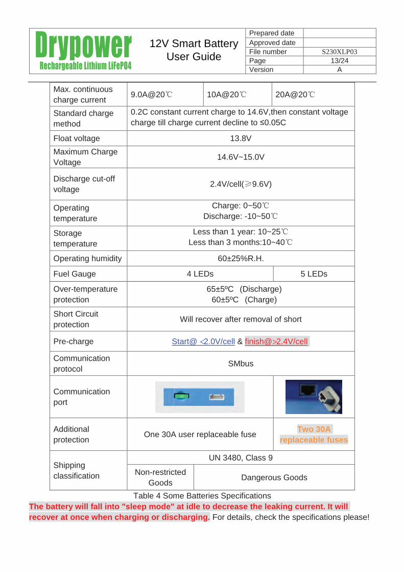
Max. continuous charge current 9.0A@20℃ 10A@20℃ 20A@20℃
Standard charge method
0.2C constant current charge to 14.6V,then constant voltagecharge till charge current decline to ≤0.05C
Float voltage 13.8VMaximum Charge Voltage 14.6V~15.0V
Discharge cut-off voltage 2.4V/cell(≥9.6V)
Operating temperature
Charge: 0~50℃Discharge: -10~50℃
Storage temperature
Less than 1 year: 10~25℃Less than 3 months:10~40℃
Operating humidity 60±25%R.H.
Fuel Gauge 4 LEDs 5 LEDs
Over-temperature protection
65±5ºC (Discharge)60±5ºC (Charge)
Short Circuit protection Will recover after removal of short
Pre-charge Start@ <2.0V/cell & finish@>2.4V/cell
Communication protocol SMbus
Communication port
Additional protection One 30A user replaceable fuse Two 30A
replaceable fuses
Shipping classification
UN 3480, Class 9
Non-restricted Goods Dangerous Goods
Table 4 Some Batteries SpecificationsThe battery will fall into "sleep mode" at idle to decrease the leaking current. It will recover at once when charging or discharging. For details, check the specifications please!
12V Smart BatteryUser Guide

Prepared date
Approved date File number S230XLP03 Page 14/24Version A
7.2 Battery characteristics (for reference only)
Figure 7 Discharge characteristic for 12V LiFePO4 battery(if applicable)
Figure 8 Life cycle characteristic for 12V LiFePO4 battery
12V Smart BatteryUser Guide

Prepared date
Approved date File number S230XLP03Page 15/24Version A
Figure 9 Discharge characteristic for 12V LiFePO4 battery
Figure 10 Charge characteristic for 12V LiFePO4 battery
12V Smart BatteryUser Guide

Prepared date
Approved date File number S230XLP03 Page 16/24Version A
8. Integrated ProtectionThe smart battery includes integrated protection circuitry to prevent the battery from exceeding its voltage limits. The battery’s circuitry interrupts either charging or discharging current if the battery is in danger of exceeding upper or lower voltage or temperature limits.8.1 Over Voltage and Under VoltageThe smart battery’s circuitry continuously monitors cellblock voltage and can interrupt either charge or discharge current in the event that a cellblock’s voltage exceeds safe operating limits.The protection circuitry interrupts current if the voltage on any single cellblock rises above 3.9Vor falls below 2.4V. If the voltage on a single cellblock falls below 2.4V, the protection circuitry enables
under-voltage protection, preventing continued discharge until you charge the battery. To avoid degradation you must recharge the battery at once. The protection circuitry disables under-voltage protection once you charge the battery to the point where all cellblocks are above 2.6 V.
If the voltage on a single cellblock rises above 3.9V, the protection circuitry enablesover-voltage protection, preventing continued charging until the voltage falls. The protection circuitry disables over-voltage protection once the voltage falls below 3.6V.
Under-voltage protection creates an open circuit, removing voltage from the terminals. With a lead-acid battery, finding no voltage at the terminals often indicates the battery has reached the end of its life. With the smart battery, no voltage at the terminals typically means the cellblock protection circuitry has interrupted current to protect the battery. Simply connect the battery to a charger to restore voltage to the terminals.8.2 Over TemperatureThe smart battery’s circuitry continuously monitors the battery’s temperature and can interrupt current if the battery exceeds 60°C (charging) or 65°C(discharging). Battery temperature must fall below 50 °C before the protection circuitry restores current.8.3 BalancingOver time, the cells inside a battery diverge in both capacity and SOC. An advantage of the smart battery is the circuitry continuously monitors the capacity and SOC of each individual cellblock and balances the battery to ensure maximum capacity. Completely balancing the battery can take up to 48 hours.8.4 Fusing30 A 32V, user-replaceable, Mini® blade fuse manufactured by LittleFuse (Part Number0297030L) protects the smart battery from short circuits if other protections failed. If required, you must replace the fuse with a new one. The use of other fuses voids your warranty.The fuse can commonly be found in automotive parts retailers as well as electronics retailers. Ensure the replacement fuse’s voltage rating is appropriate for your application.
12V Smart BatteryUser Guide

Prepared date
Approved date File number S230XLP03 Page 17/24Version A
9 Troubleshooting
The smart batteries provide greater useful life than comparable lead-acid batteries. Despite the
high reliability of the smart batteries, you may encounter situations where the battery does not
operate as expected. These situations are typically the result of misuse, abuse or a non-optimal
operating or storage environment. This chapter details potential issues you may encounter with
the smart batteries and the appropriate troubleshooting procedures.
9.1 Charger Trips using Constant Voltage
Problem:CV charger trips when charging the smart battery. This is due to the low impedance of
the battery creating a current inrush.
Solution: Reset the charger and try again.
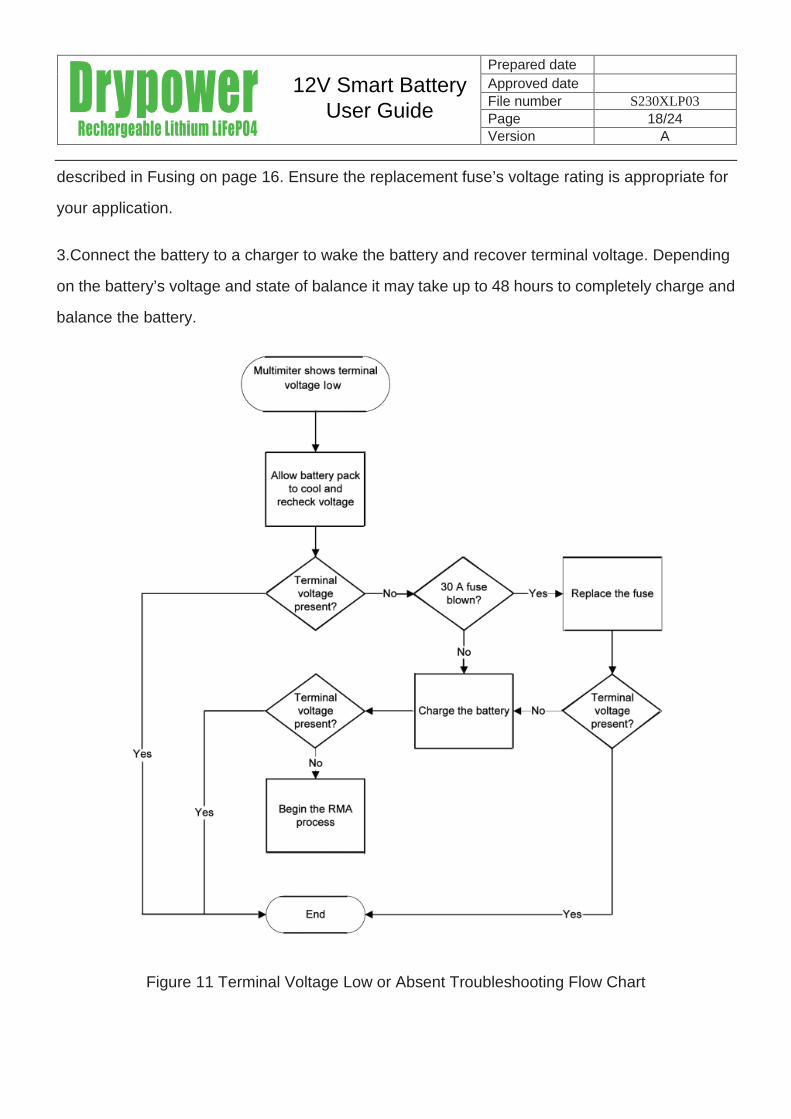
9.2 Terminal Voltage Absent or Low
Problem: Using a multi-meter to check terminal voltage shows the terminal voltage is low.
Possible causes for this problem are:
Blown fuse
The voltage of a cellblock within the battery dropped below 2.4V, causing the microprocessor
to enable under-voltage protection.
The battery’s SOC dropped below 5% from either an extended idle period or heavy use,
enabling under-voltage protection.
The battery overheated, causing the microprocessor to enable over-temperature protection.
Solution: To resolve situations where terminal voltage is absent or low:
1.Allow the battery to cool and then re-check terminal voltage.
2.Inspect the fuse and replace it if necessary. Use only fuses that meet the specifications
12V Smart BatteryUser Guide
Prepared date
Approved date File number S230XLP03 Page 18/24Version A
described in Fusing on page 16. Ensure the replacement fuse’s voltage rating is appropriate for
your application.
3.Connect the battery to a charger to wake the battery and recover terminal voltage. Depending
on the battery’s voltage and state of balance it may take up to 48 hours to completely charge and
balance the battery.
Figure 11 Terminal Voltage Low or Absent Troubleshooting Flow Chart
12V Smart BatteryUser Guide

Prepared date
Approved date File number S230XLP03 Page 19/24Version A
9.3 Battery Rapidly Depletes Energy between Charges
Problem: The battery rapidly depletes its energy between charging. Possible causes for this
problem are:
The battery is out-of-balance.
The battery has reached the end of its useful service life.
Solution: To resolve situations where the battery rapidly depletes its energy between charges:
1.Apply a float charge (13.8 V) for 48 hours to balance the battery pack’s cells.
2.Replace the battery.
9.4 Battery Current Disappears when Charging
Problem: Battery current disappears when charging. Possible causes for this problem are:
The battery overheated, enabling over-temperature protection.
The battery is out-of-balance.
Charger voltage is too high.
Solution: To resolve situations where current disappears when charging:
1.Allow the battery to cool.
2.Apply a float charge (13.8 V) for 48 hours to balance the battery’s cellblocks. For more details
on charging battery or battery system, refer to page 9.
3.Reduce charger voltage to 14.6 V or less.
9.5 30 A Fuse Blows Frequently
12V Smart BatteryUser Guide

Prepared date
Approved date File number S230XLP03 Page 20/24Version A
Problem: The user -replaceable 30 A fuse blows frequently. Possible causes for this problem
are:
The fuse was replaced with a fuse that does not meet the specifications detailed in
User-Replaceable Fuse on page 16.
Failure to ensure correct polarity when connecting the battery to other batteries or a device’s
output terminals.
The battery exceeded maximum current specifications while charging or discharging the
battery.
Solution: To resolve situations where the battery’ s 30 A fuse blows frequently:
1.Ensure you are using a fuse that meets the fuse specifications detailed in User-Replaceable
Fuse on page 16.
2.Verify correct polarity on all connections.
3.Do not exceed maximum current specifications while charging or discharging the battery.
9.6 Voltage Drops Abruptly
Problem: Battery voltage appears constant, then drops abruptly.
Solution: This is normal for LiFePO4 cells. Constant voltage throughout the battery’s SOC
ensures maximum usable life. Once the voltage of a cell within the module drops below 2.4V, the
smart battery’s circuitry enables under-voltage protection, which creates an open circuit at the
terminals.
12V Smart BatteryUser Guide

Prepared date
Approved date File number S230XLP03 Page 21/24Version A
10 TIPS FOR OPTIMIZING PERFORMANCE
By following the tips listed below, one can assure long life and high performance of the battery: Charge all batteries fully prior to first use of the device. Allow battery to charge fully over night periodically. Use at temperatures 10℃~25℃. Charge battery to 30~50% SOC prior to long storage periods. Charge/discharge battery once after it is has been stored for more than two (2) months. Ensure that all batteries are secured into position to minimize damage from shock and
vibration Periodically inspect electrical connections to ensure screws are tight and no corrosion is
present. Proper thermal management will maximize life. This includes adequate air cooling. If a battery is replaced, all battery should be at the same state of charge when placed into the
pack.
11 MAINTENANCE AND STORAGE
11.1 Visual Inspection
Please perform regular visual inspections of the battery case. If the battery case is found to have dents, discoloration, or appears to be damaged in any way, DISCONTINUE USE IMMEDIATELY. Please contact your place of purchase for assistance with evaluating the product for continuedusability.
11.2 Voltage Checking
The voltage of the battery can be monitored during normal operation or as part of standard tests performed periodically to assess the health of the battery. If you find any single battery’s voltage is under 10V at room temperature, the battery has been over-discharged or is self-discharging due to some defect/parasitic load. Discontinue use until the fault can be corrected and the battery be recharged.
11.3 Battery Storage
Test the open circuit voltage periodically and recharge if it is at or below 12V. Monthly tests are recommended.
Store in an open, well ventilated, dry, clean area, between10℃ and 25℃ (50°F and 77°F) for maximum life. Self discharge is accelerated at higher temperatures
Do not expose the battery to extremes of temperature over 50℃ (122°F). Do not expose the battery directly to sources of heat. Do not expose the battery to direct sunlight or moisture and/or precipitation.
12V Smart BatteryUser Guide

Prepared date
Approved date File number S230XLP03 Page 22/24Version A
Handle each battery carefully to avoid sharp impacts or extreme pressure on the case.
12 TRANSPORTATION AND SHIPPING
When transporting or moving the battery within your installation, please follow the guidelinesbelow. Avoid heavy vibration during transportation. Avoid throwing, rolling and excessive stacking during loading and transportation. Make sure that all cables and external connectors are disconnected and removed from the
battery prior to moving it.
If the battery needs to be shipped to a different location or sent back to your place of purchase, for any reason, please follow the guidelines below carefully. Disconnect all cables, both power and communications from the batteries. Pack the batteries in “dangerous goods” certified boxes and packing materials as specified
by the Department of Transportation (DOT). The packing must protect the contents from reason able handling damage and prevent short circuits from taking place. Ideally, one would use the original box if it’s still in good condition (See Note Below)
The package should be prepared for shipment and shipping documents should be signed by individual who is certified to handle and prepare products that have been designated as “Dangerous Goods” for shipment.
Ship under regulations UN 3480, Class 9 –"non-restricted Goods" or “Dangerous Goods”.Importance Note: the battery is shipped in a specially designed box to provide maximum protection for the contents. We strongly recommend that you save this box and use it whenever you need to transport or ship the battery. Please follow all local laws /regulations regarding the shipment of lithium-ion batteries.
13 BATTERY OVERHEATINGIf the charger malfunctions to overcharge the battery past 100% for a given amount of time ANDthe safety disconnect device fails or is not in place, the battery can be damaged beyond repair, and in some cases get extremely hot possibly releasing smoke and melting plastic.
13.1 Emergency Procedures for a Melting or Smoking Battery
If a battery begins to smoke or melt remove charging source immediately.
12V Smart BatteryUser Guide

Prepared date
Approved date File number S230XLP03Page 23/19Version A0
If possible move the battery to well ventilated area, preferably outside. Use a fire extinguisher, either carbon dioxide, dry chemical or appropriate foam to spray the
hot battery. If a fire extinguisher is not available, use copious amounts of water, or cover the battery with sand.
13.2 Emergency and First Aid Procedures for Human Contact/Exposure to Battery Content
In the event of exposure to battery contents the following could occur: Vapor or mist is irritating to the eyes, mucous membranes and respiratory tract. Causes eye and skin irritation. Exposure can cause nausea, dizziness and headache.In case of contact with the battery’s electrolyte: Immediately flush eyes with copious amounts of water for at least 15 minutes. Assure adequate flushing of the eyes by separating the eyelids with fingers. Flush skin with water Remove and wash contaminated clothing promptly.
If inhaled: Remove oneself to fresh air.
If not breathing or difficulty breathing: Give artificial respiration. If breathing is difficult, give oxygen.
If swallowed: Wash out mouth with water provided person is conscious.In all cases – CALL A PHYSICIAN!
14 DISPOSAL OF BATTERIES
Most councils offer regular collections and/or provide drop-off locations for hazardous waste.
Contact your local council for information specific to your area, or visit Planet Ark’s recycling initiative Recycling Near You: www.recyclingnearyou.com.au or call the hotline 1300 733 712 for information on hazardous waste and disposal options.
12V Smart BatteryUser Guide

Prepared date
Approved date File number S230XLP03Page 24/24Version A0
Batteries have residual electrical charge. Please be sure to completely discharge batteries before disposing them.
If you are not sure if your waste facility can handle lithium-ion batteries, contact them and verify if they are permitted or not.
14.1 Recycling
There are a number of other local programs for recycling batteries.
Search http://recyclingnearyou.com.au/batteries to find collection points in your local area.
15 USE IN LIFE SUPPORT APPLICATIONS
The battery SHALL NOT be used in, or in conjunction with, any Life Support Application without the express written consent of Drypower. Life Support Applications includes, without limitation: (i)a device to be implanted in a human body; or (ii) a system or device, which supports or monitors a human life, such that its failure could cause serious injury or death.
12V Smart BatteryUser Guide