
Dry Pump Technology - VACUUM SYMPOSIUM Pump Technology Today… · Dry Pump Technology R Gordon...
45
Lynthorpe Consultancy Dry Pump Technology R Gordon Livesey
Transcript of Dry Pump Technology - VACUUM SYMPOSIUM Pump Technology Today… · Dry Pump Technology R Gordon...
Lynthorpe Consultancy
Dry Pump Technology
R Gordon Livesey
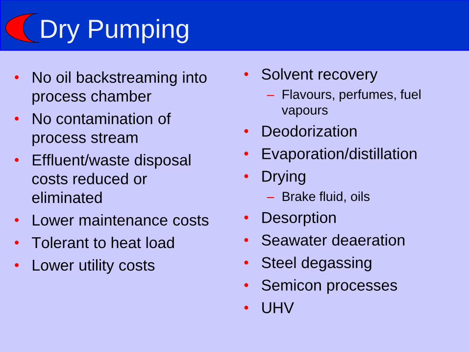
Dry Pumping
• No oil backstreaming into
process chamber
• No contamination of
process stream
• Effluent/waste disposal
costs reduced or
eliminated
• Lower maintenance costs
• Tolerant to heat load
• Lower utility costs
• Solvent recovery
– Flavours, perfumes, fuel
vapours
• Deodorization
• Evaporation/distillation
• Drying
– Brake fluid, oils
• Desorption
• Seawater deaeration
• Steel degassing
• Semicon processes
• UHV
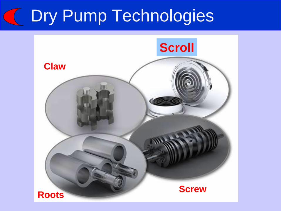
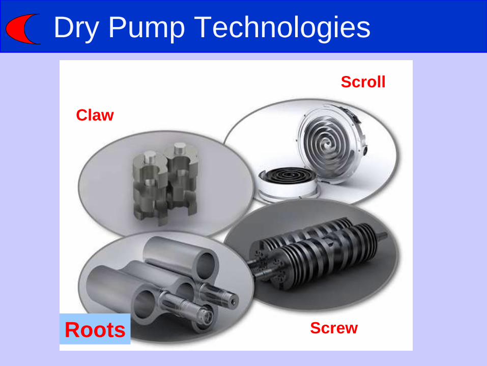
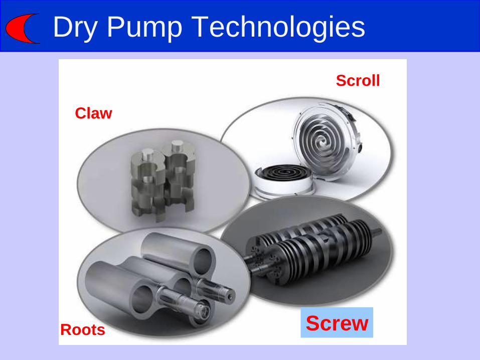
Dry Pump Technologies
Roots
Claw
Screw
Scroll

Scroll Pumps
• Comprises two opposing
scrolls
• One scroll is fixed and
the other orbits
• Each has a seal in the
scroll end
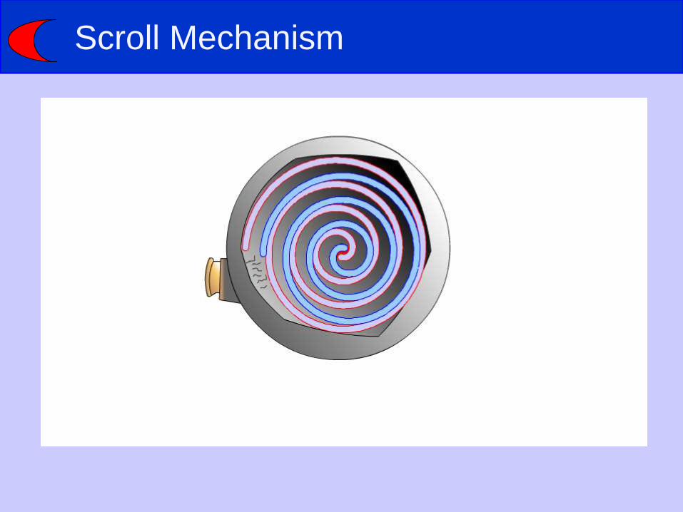
Scroll Mechanism
Scroll Pump
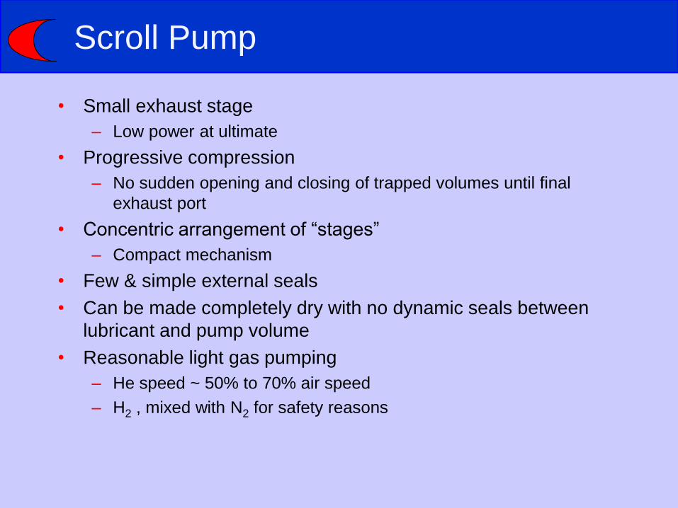
• Small exhaust stage
– Low power at ultimate
• Progressive compression
– No sudden opening and closing of trapped volumes until final
exhaust port
• Concentric arrangement of “stages”
– Compact mechanism
• Few & simple external seals
• Can be made completely dry with no dynamic seals between
lubricant and pump volume
• Reasonable light gas pumping
– He speed ~ 50% to 70% air speed
– H2 , mixed with N2 for safety reasons

Scroll Pump
• Difficult to extract heat from the exhaust stages
– Small size, located on axis
• Seal wear generates dust – Mainly in first 100 hours, not a major problem if no suckback
– Successfully used in electron microscopes which are very sensitive to dust
• Seals require frequent maintenance
• Highly vulnerable to solid material ingestion
• Clearances controlled at “whole pump level”
– Less easy to control critical exhaust clearances
• Only small capacity pumps available – difficult to scale to large sizes

Dry Pump Technologies
Roots
Claw
Screw
Scroll
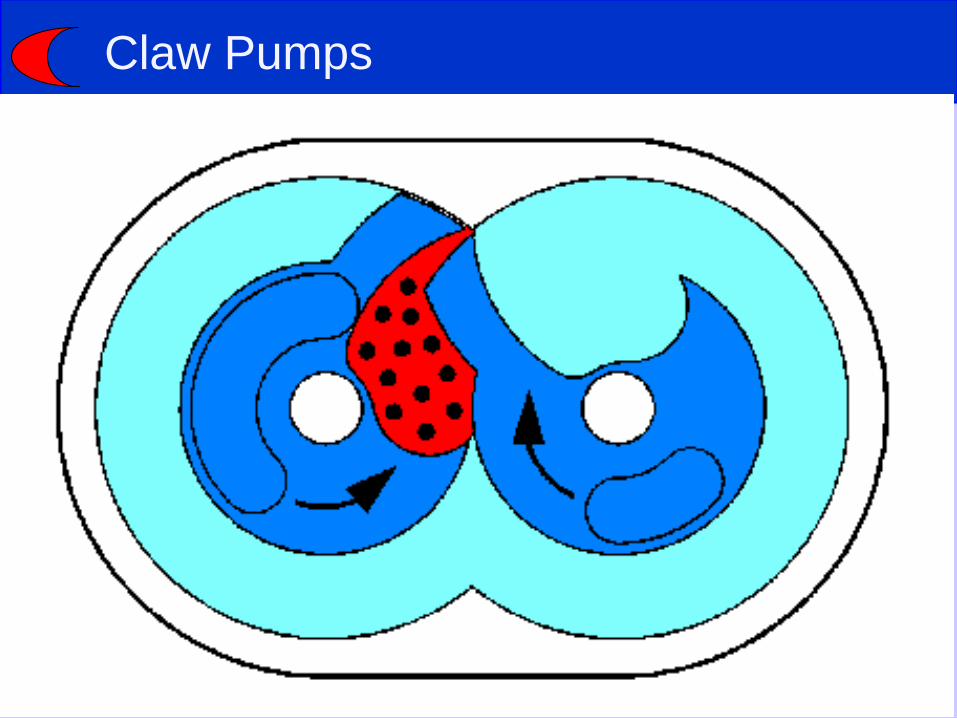
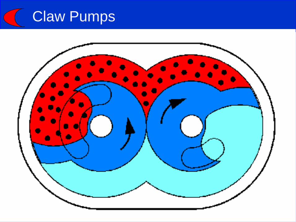
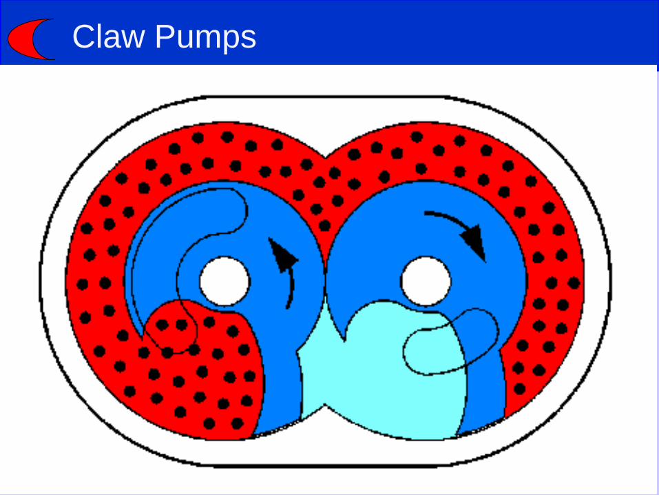
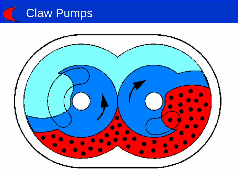
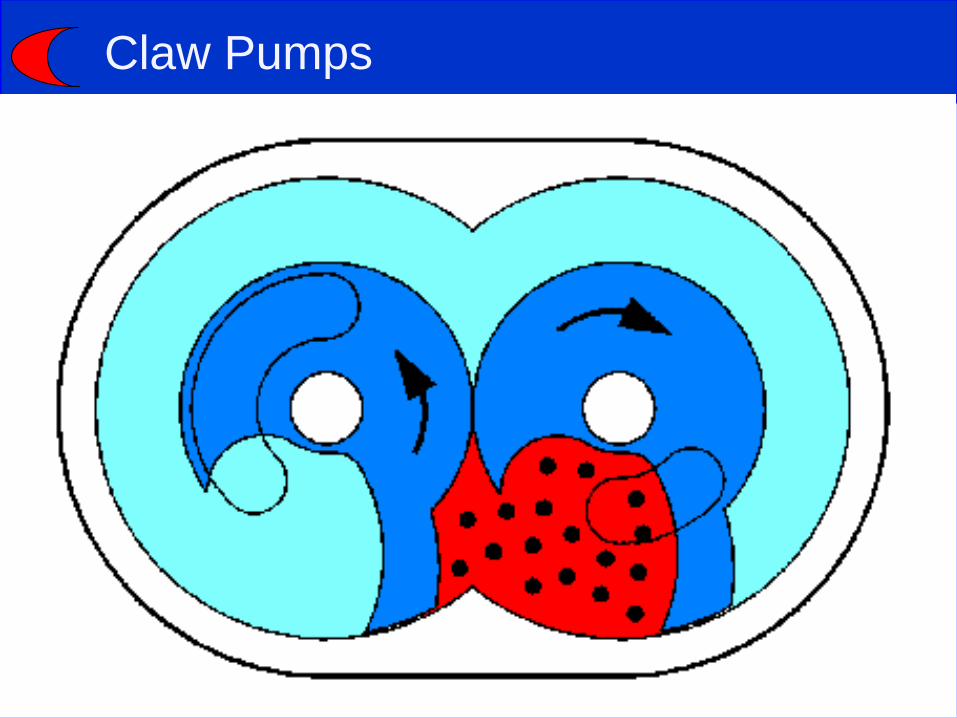
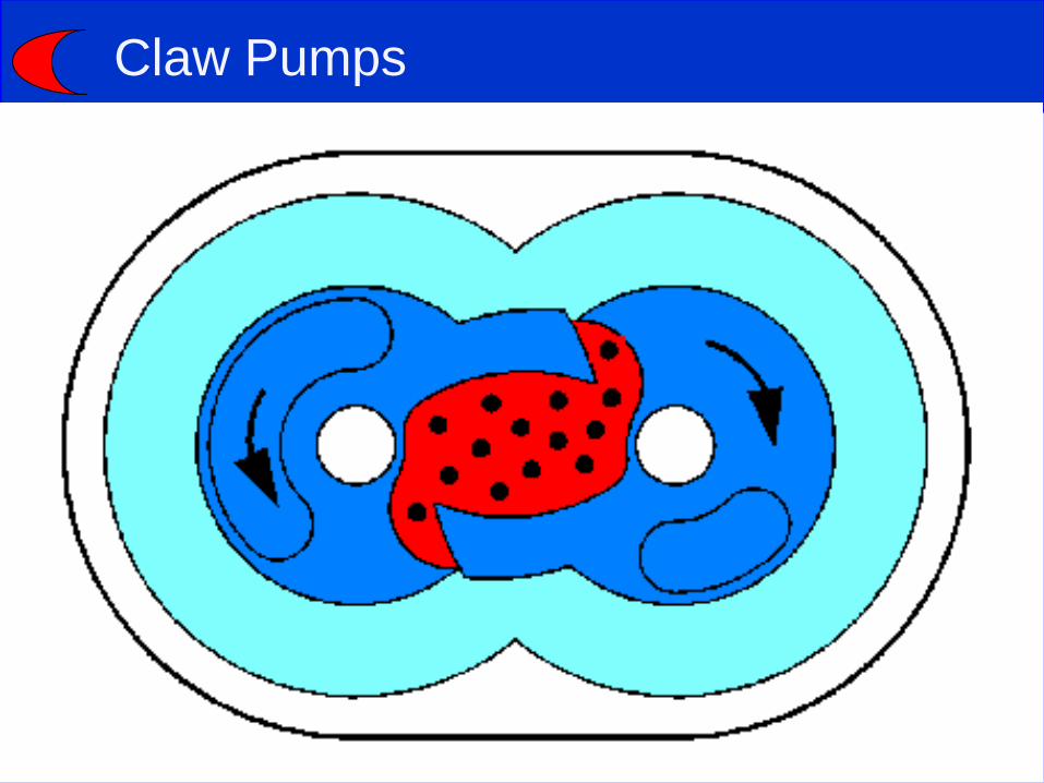
Claw Pumps

Claw Pumps
Claw Pumps
Claw Pumps

Claw Pumps

Claw Pumps

Claw Pumps

Claw Pumps
Claw Pumps
Claw Pumps
Claw Pumps
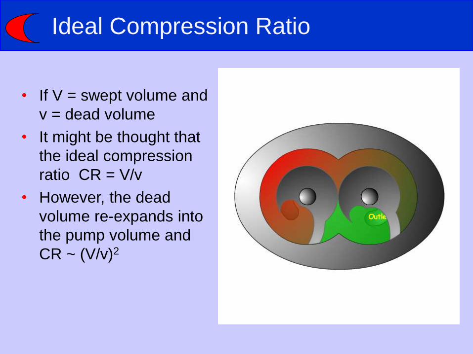
Ideal Compression Ratio
• If V = swept volume and
v = dead volume
• It might be thought that
the ideal compression
ratio CR = V/v
• However, the dead
volume re-expands into
the pump volume and
CR ~ (V/v)2

Claw Pumps
• Good compression
• Compression through pump can
be controlled by sizing stages
– Relatively easy to produce
small capacity / low power
outlet stages
• Reversed claws allow straight
path – good dust handling
• Can handle liquid ingestion
• Can be scaled up to moderately
large capacities
• Self valving – can exhaust to high
pressure
INLET
EXHAUST
Claw Pumps
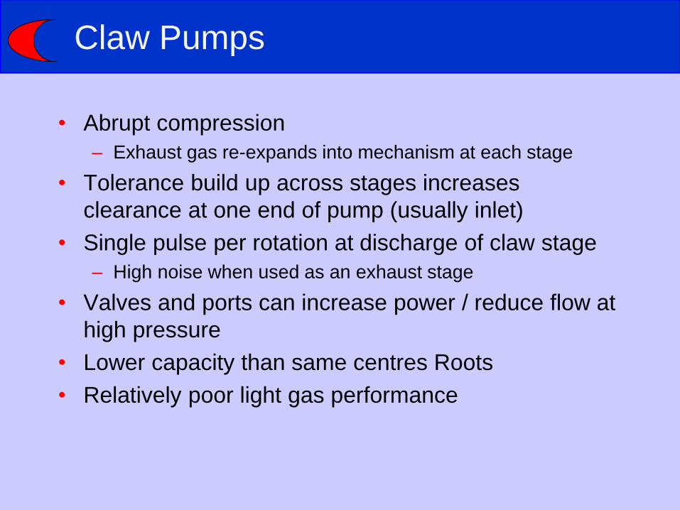
• Abrupt compression
– Exhaust gas re-expands into mechanism at each stage
• Tolerance build up across stages increases
clearance at one end of pump (usually inlet)
• Single pulse per rotation at discharge of claw stage
– High noise when used as an exhaust stage
• Valves and ports can increase power / reduce flow at
high pressure
• Lower capacity than same centres Roots
• Relatively poor light gas performance
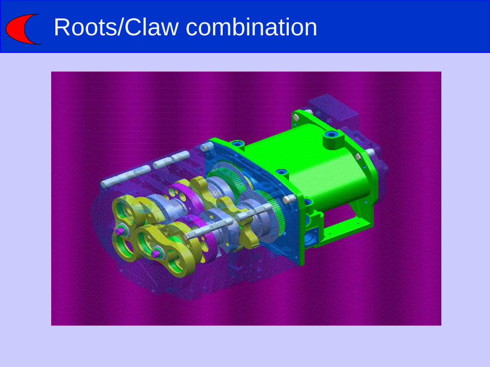
Roots/Claw combination
Dry Pump Technologies
Roots
Claw
Screw
Scroll

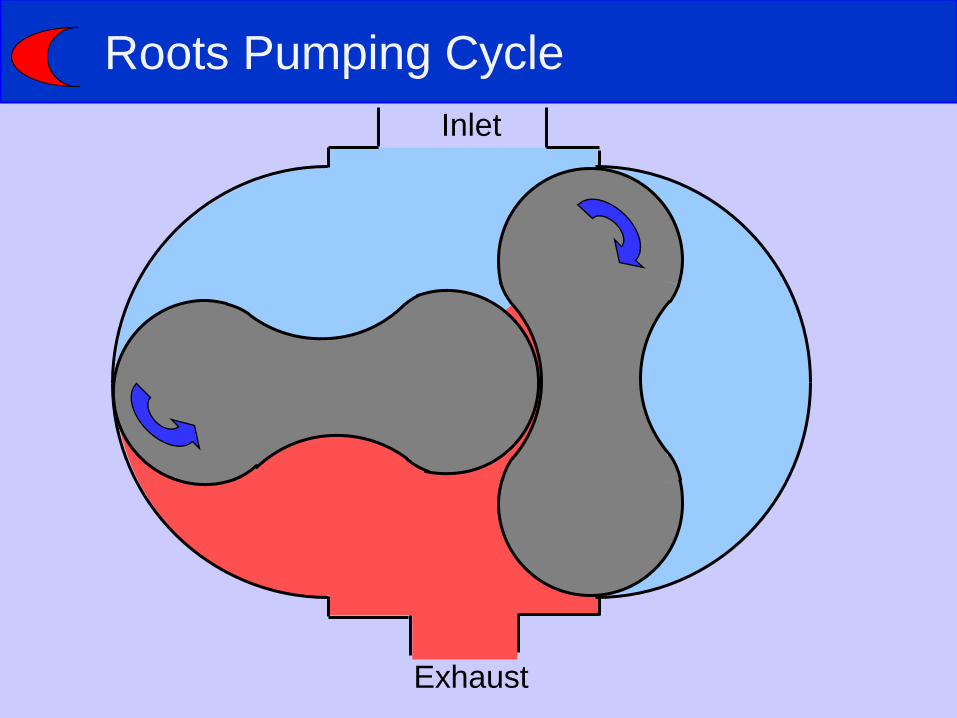
Roots Pumping Cycle
Inlet
Exhaust
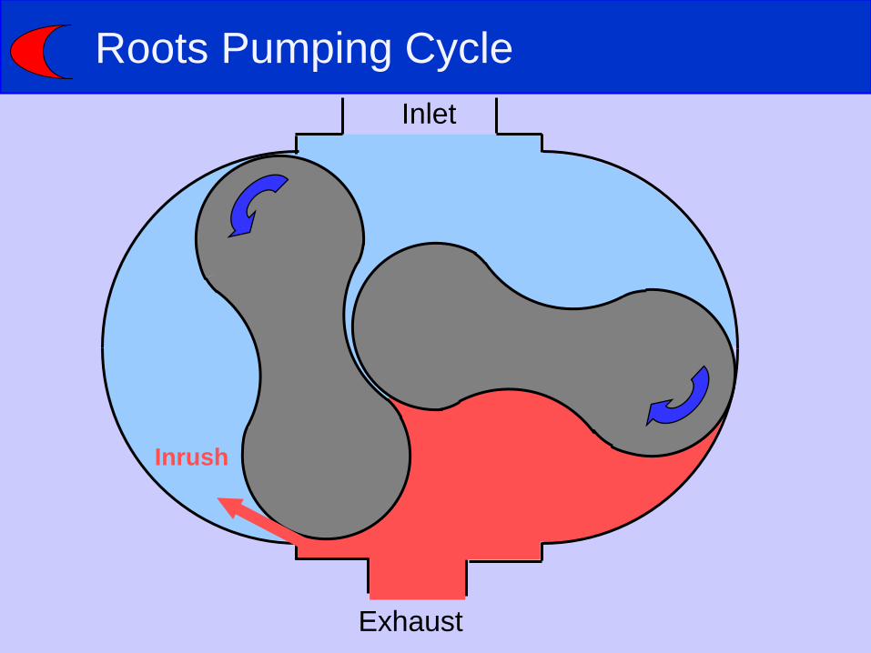
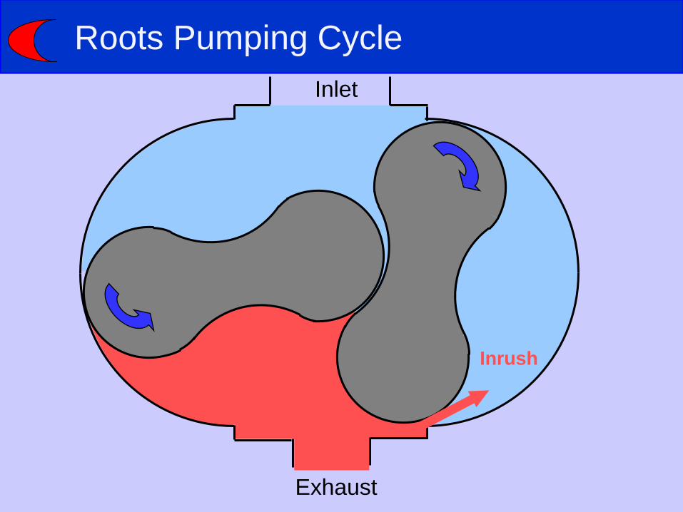
Roots Pumping Cycle
Inlet
Exhaust
Inrush

Roots Pumping Cycle
Inlet
Exhaust
Roots Pumping Cycle
Inlet
Exhaust
Roots Pumping Cycle
Inlet
Exhaust
Inrush
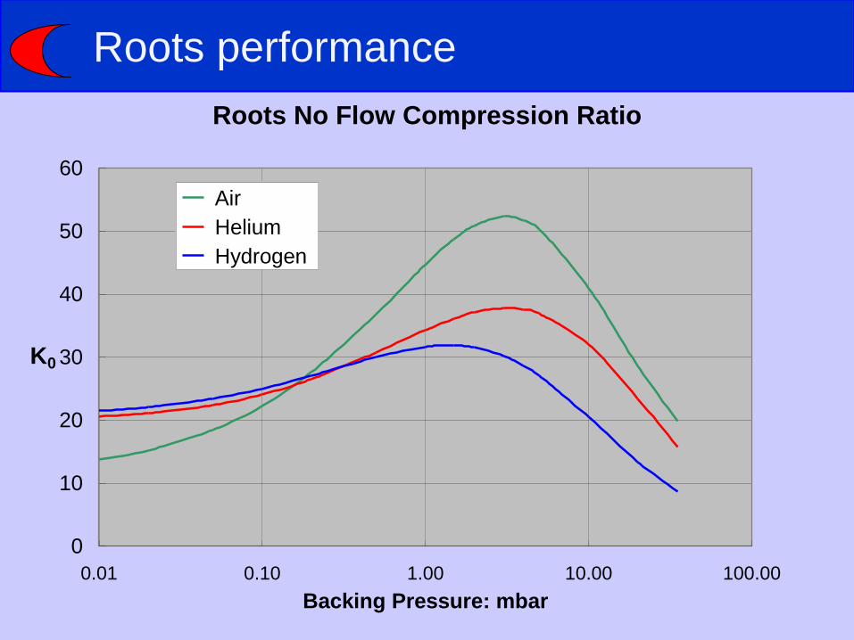
Roots performance
Roots No Flow Compression Ratio
0
10
20
30
40
50
60
0.01 0.10 1.00 10.00 100.00
Backing Pressure: mbar
K0
Air
Helium
Hydrogen

Root Trapping
Gas trapped
& compressed
Inlet
Exhaust
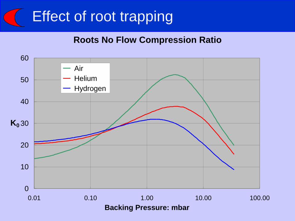
Effect of root trapping
Roots No Flow Compression Ratio
0
10
20
30
40
50
60
0.01 0.10 1.00 10.00 100.00
Backing Pressure: mbar
K0
Air
Helium
Hydrogen
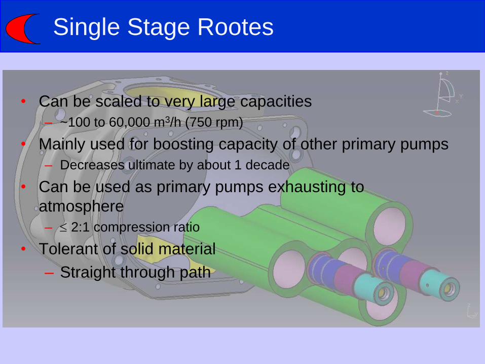
Single Stage Rootes
• Can be scaled to very large capacities
– ~100 to 60,000 m3/h (750 rpm)
• Mainly used for boosting capacity of other primary pumps
– Decreases ultimate by about 1 decade
• Can be used as primary pumps exhausting to
atmosphere
– 2:1 compression ratio
• Tolerant of solid material
– Straight through path
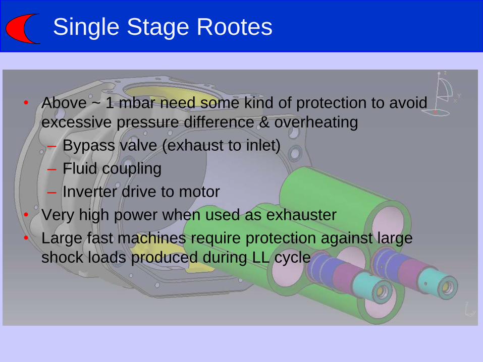
Single Stage Rootes
• Above ~ 1 mbar need some kind of protection to avoid
excessive pressure difference & overheating
– Bypass valve (exhaust to inlet)
– Fluid coupling
– Inverter drive to motor
• Very high power when used as exhauster
• Large fast machines require protection against large
shock loads produced during LL cycle
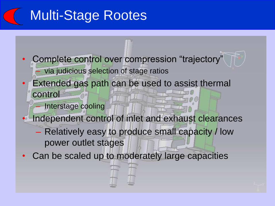
Multi-Stage Rootes
• Complete control over compression “trajectory”
– via judicious selection of stage ratios
• Extended gas path can be used to assist thermal
control
– Interstage cooling
• Independent control of inlet and exhaust clearances
– Relatively easy to produce small capacity / low
power outlet stages
• Can be scaled up to moderately large capacities
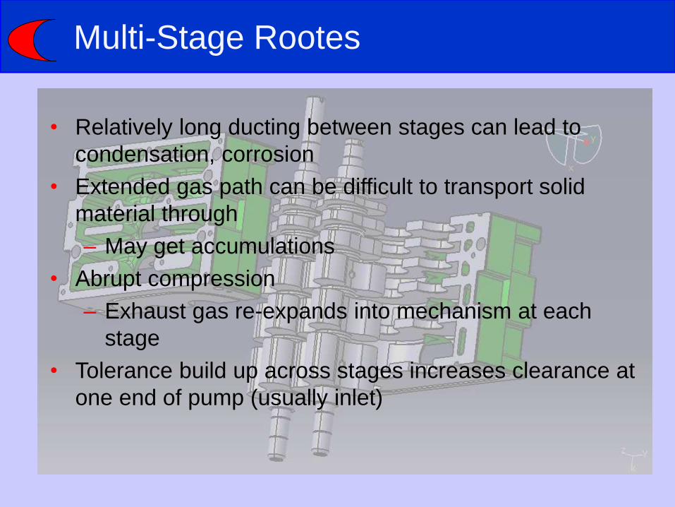
Multi-Stage Rootes
• Relatively long ducting between stages can lead to
condensation, corrosion
• Extended gas path can be difficult to transport solid
material through
– May get accumulations
• Abrupt compression
– Exhaust gas re-expands into mechanism at each
stage
• Tolerance build up across stages increases clearance at
one end of pump (usually inlet)

Exhaust Cooling
Dry Pump Technologies
Roots
Claw
Screw
Scroll
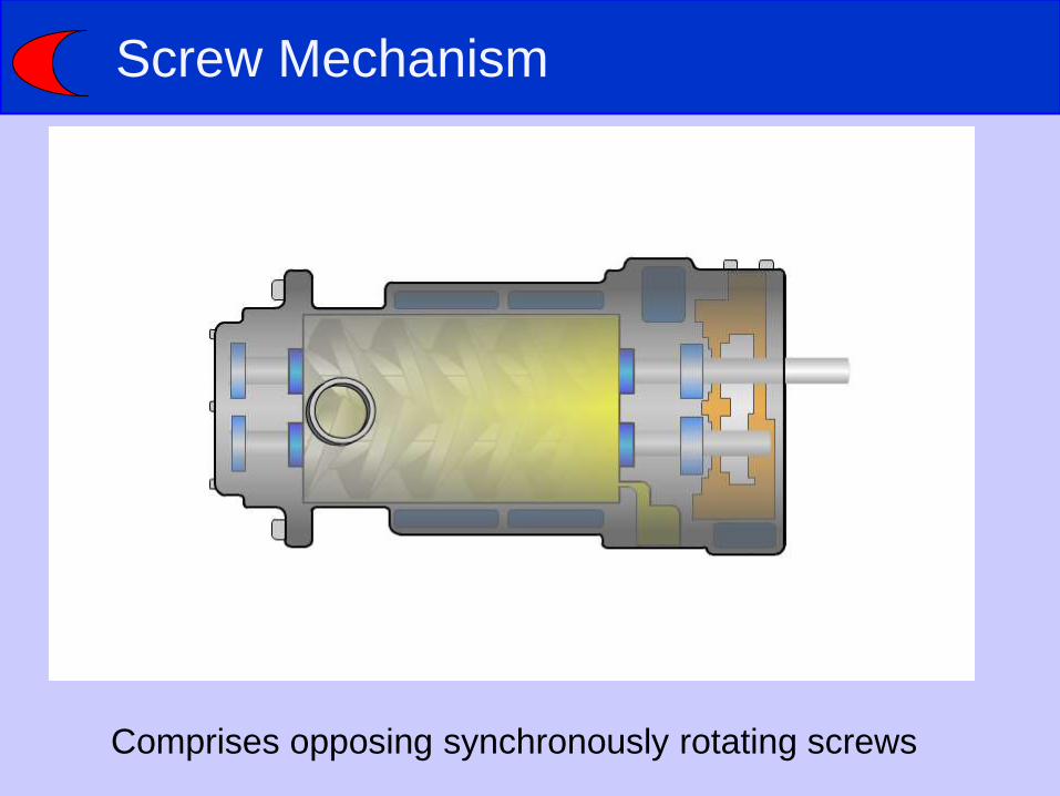
Screw Mechanism
Comprises opposing synchronously rotating screws
Screw
• Excellent handling of solid
material
• Progressive compression
– With tapers, variable
pitch etc.
– No sudden re-
expansion until final
exhaust port
• Compression “trajectory”
can be designed
• Can be scaled up to
moderately large
capacities
• Tip clearance critical to
overall performance
– Direct “line of sight” from
outlet to inlet
– Performance can
depend on “history”
(temperature, flow)
• Clearances controlled at
“whole pump level”
• More difficult to make small
capacity machines /
machines with small
exhaust stages?
• Second generation
– Variable pitch Quimby screw • Two separate screws bolted together (2-stage)
• Expensive to manufacture
• Typically 1.8:1 compression
• Lower power than constant pitch
[Power (kW) = Swept volume of stage (m3/s) x delta P (Pa)]
1st Generation – Single Pitch ‘Queen Bee’ or Quimby
cut
2nd Generation – Variable Pitch ‘Queen Bee’ or
Quimby cut
3rd Generation – Variable Pitch Square Cut screw with
no compression plate.
4th Generation – Tapered Variable Pitch Square Cut
screw with no compression plate.
• 1st generation: single pitch, Quimby screws: • Inherently well sealed screw profile – “conjugate screws”
• High swept volumes
• Generally machined on expensive Holroyd machines
• Matched rotor pairs
• Compression against exhaust valve plate very high exhaust
temperatures
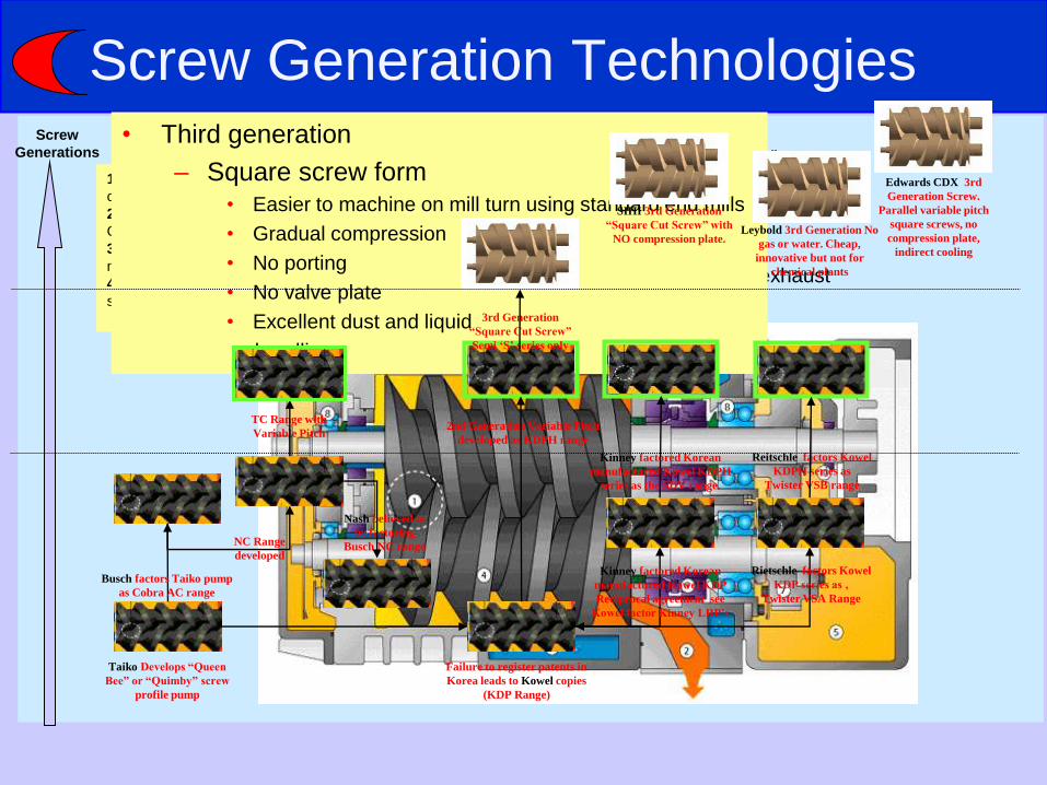
• Third generation
– Square screw form • Easier to machine on mill turn using standard end mills
• Gradual compression
• No porting
• No valve plate
• Excellent dust and liquid
handling
Screw Generation Technologies
Taiko Develops “Queen
Bee” or “Quimby” screw
profile pump
Failure to register patents in
Korea leads to Kowel copies
(KDP Range)
Busch factors Taiko pump
as Cobra AC range
NC Range
developed
Nash believed to
be factoring
Busch NC range
2nd Generation Variable Pitch
developed as KDPH range
TC Range with
Variable Pitch
3rd Generation
“Square Cut Screw”
Semi ‘S’ series only
Rietschle factors Kowel
KDP series as ‚
Twister VSA Range
Kinney factored Korean
manufactured Kowel KDP
Reciprocal agreement see
Kowel factor Kinney LRP’s
Kinney factored Korean
manufactured Kowel KDPH
series as the SDV range.
Reitschle factors Kowel
KDPH series as
Twister VSB range
SIHI 3rd Generation
“Square Cut Screw” with
NO compression plate.
Edwards CDX 3rd
Generation Screw.
Parallel variable pitch
square screws, no
compression plate,
indirect cooling
Leybold 3rd Generation No
gas or water. Cheap,
innovative but not for
chemical plants
Screw
Generations

Square Screw Design
• Stepped changes of pitch –
don’t blend into each other
so harder to manufacture
• Tapered design
• Discrete variable pitch for
good thermal control
• Tip leakage limits pitch &
hence swept volume –
compromises light gas
performance
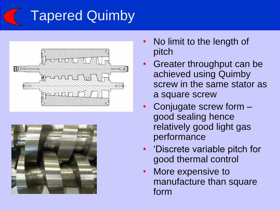
Tapered Quimby
• No limit to the length of pitch
• Greater throughput can be achieved using Quimby screw in the same stator as a square screw
• Conjugate screw form – good sealing hence relatively good light gas performance
• ‘Discrete variable pitch for good thermal control
• More expensive to manufacture than square form
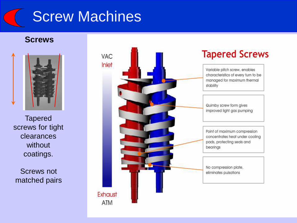
Screw Machines
Screws
Tapered
screws for tight
clearances
without
coatings.
Screws not
matched pairs

Finally
• Thanks to Edwards for information and illustrations
• However, presentation and any errors or omissions
are entirely my responsibility