Dry Compressing Dry Com Vacuum Pumps - Ideal · PDF fileCatalog Part Dry Compressing Vacuum...
64
Dry Com DIVAC Diaphragm Vacuum Pumps SCROLLVAC Scroll Vacuum Pumps LEYVAC / SCREWLINE Screw Vacuum Pumps DRYVAC Screw Vacuum Pumps Dry Compressing Vacuum Pumps 220.00.02 Excerpt from the Leybold Full Line Catalog 2016 Catalog Part Dry Compressing Vacuum Pumps Edition: Fall 2016
Transcript of Dry Compressing Dry Com Vacuum Pumps - Ideal · PDF fileCatalog Part Dry Compressing Vacuum...
Dry ComDIVAC Diaphragm Vacuum PumpsSCROLLVAC Scroll Vacuum PumpsLEYVAC / SCREWLINE Screw Vacuum PumpsDRYVAC Screw Vacuum Pumps
Dry Compressing Vacuum Pumps
220.00.02Excerpt from the Leybold Full Line Catalog 2016Catalog Part Dry Compressing Vacuum PumpsEdition: Fall 2016

leyboldLeybold Full Line Catalog Fall 20162
Dry Compressing Vacuum PumpsGlobal Versions
Diaphragm Vacuum Pumps DIVAC . . . . . . . . . . . . . . . . . . . . . . . . . . . . 4General
DIVAC Program Overview . . . . . . . . . . . . . . . . . . . . . . . . . . . . . . . . . . . . . . . . . . . . 4
The customized Diaphragm Pump and the Accessories recommended for your Applications . . . . . . . . . 5
Modular Diaphragm Pump System for the Chemical Laboratory . . . . . . . . . . . . . . . . . . . . . . . . 5
Products
Diaphragm Vacuum Pumps for the Chemical Laboratory . . . . . . . . . . . . . . . . . . . . . . . . . 6
Dual-Stage Diaphragm Vacuum Pumps DIVAC 0 .6 L, 1 .2 L, 2 .2 L . . . . . . . . . . . . . . . . . . . . . . . . . . . . . . . . . . . . . . . . . . 6
Three-Stage Diaphragm Vacuum Pumps DIVAC 1 .4 HV3C . . . . . . . . . . . . . . . . . . . . . . . . . . . . . . . . . . . . . . . . . . . . . . 8
Dry Compressing Backing Pumps for Turbomolecular Pumps . . . . . . . . . . . . . . . . . . . . . . 10
DIVAC 0 .8 T and 0 .8 LT . . . . . . . . . . . . . . . . . . . . . . . . . . . . . . . . . . . . . . . . . . . 12
DIVAC 1 .4 HV3 and 3 .8 HV3 . . . . . . . . . . . . . . . . . . . . . . . . . . . . . . . . . . . . . . . . . 14
DIVAC 4 .8 VT . . . . . . . . . . . . . . . . . . . . . . . . . . . . . . . . . . . . . . . . . . . . . . . . 16
Scroll Vacuum Pumps SCROLLVAC . . . . . . . . . . . . . . . . . . . . . . . . . . . 18General
Applications and Accessories for SCROLLVAC Pumps . . . . . . . . . . . . . . . . . . . . . . . . . . . . 18
Products
Oil-free Scroll Vacuum Pumps SCROLLVAC SC 5 D to SC 60 D . . . . . . . . . . . . . . . . . . . . . . . 19
Screw Vacuum Pumps LEYVAC . . . . . . . . . . . . . . . . . . . . . . . . . . . . . . 25General
Applications for LEYVAC Pumps . . . . . . . . . . . . . . . . . . . . . . . . . . . . . . . . . . . . . . . 25
General . . . . . . . . . . . . . . . . . . . . . . . . . . . . . . . . . . . . . . . . . . . . . . . . . . . . 26
Products
LEYVAC LV 80 to LV 140 C . . . . . . . . . . . . . . . . . . . . . . . . . . . . . . . . . . . . . . . . . 28
Contents
Dry
Com
pres
sing
Vacu
um P
umps
leybold Leybold Full Line Catalog Fall 2016 3
Screw Vacuum Pumps SCREWLINE . . . . . . . . . . . . . . . . . . . . . . . . . . . 31General
Applications for SCREWLINE Pumps . . . . . . . . . . . . . . . . . . . . . . . . . . . . . . . . . . . . . 31
General SCREWLINE SP 250 to SP 630 (F) . . . . . . . . . . . . . . . . . . . . . . . . . . . . . . . . . 32
Products
SCREWLINE SP 250 . . . . . . . . . . . . . . . . . . . . . . . . . . . . . . . . . . . . . . . . . . . . 36
SCREWLINE SP 630 . . . . . . . . . . . . . . . . . . . . . . . . . . . . . . . . . . . . . . . . . . . . 38
Screw Vacuum Pumps DRYVAC . . . . . . . . . . . . . . . . . . . . . . . . . . . . . 42General
Applications for DRYVAC Pumps . . . . . . . . . . . . . . . . . . . . . . . . . . . . . . . . . . . . . . . 42
Oil for DRYVAC pumps, for different fields of application . . . . . . . . . . . . . . . . . . . . . . . . . . . 43
Oil for DRYVAC pumps, for different pump types . . . . . . . . . . . . . . . . . . . . . . . . . . . . . . . 44
General DRYVAC DV 450 to DVR 5000 C-i . . . . . . . . . . . . . . . . . . . . . . . . . . . . . . . . . 45
Products
DRYVAC DV / DV S / DV C . . . . . . . . . . . . . . . . . . . . . . . . . . . . . . . . . . . . . . . . . 54
Versions for the North and South American Continents
Dry Vacuum Pumps CHEMROVAC TRV for Chemical and Pharmaceutical Applications . . . . . . . . . . . . . . . . . . . . . 58General
Applications for CHEMROVAC Pumps . . . . . . . . . . . . . . . . . . . . . . . . . . . . . . . . . . . . 58
Products
CHEMROVAC TRV 404 to 410 . . . . . . . . . . . . . . . . . . . . . . . . . . . . . . . . . . . . . . . 60
leyboldLeybold Full Line Catalog Fall 20164
General
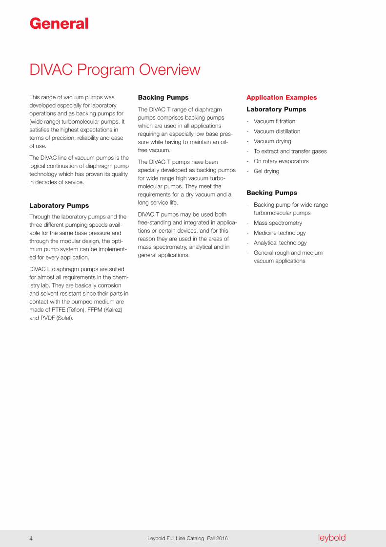
Application Examples
Laboratory Pumps
- Vacuum filtration
- Vacuum distillation
- Vacuum drying
- To extract and transfer gases
- On rotary evaporators
- Gel drying
Backing Pumps
- Backing pump for wide range turbomolecular pumps
- Mass spectrometry
- Medicine technology
- Analytical technology
- General rough and medium vacuum applications
Backing Pumps
The DIVAC T range of diaphragm pumps comprises backing pumps which are used in all applications re quiring an especially low base pres-sure while having to maintain an oil-free vacuum .
The DIVAC T pumps have been spe cially developed as backing pumps for wide range high vacuum turbo-molecular pumps . They meet the requirements for a dry vacuum and a long service life .
DIVAC T pumps may be used both free-standing and integrated in applica-tions or certain devices, and for this reason they are used in the areas of mass spectrometry, analytical and in general applications .
This range of vacuum pumps was developed especially for laboratory operations and as backing pumps for (wide range) turbomolecular pumps . It satisfies the highest expectations in terms of precision, reliability and ease of use .
The DIVAC line of vacuum pumps is the logical continuation of diaphragm pump technology which has proven its quality in decades of service .
Laboratory Pumps
Through the laboratory pumps and the three different pumping speeds avail-able for the same base pressure and through the modular design, the opti-mum pump system can be implement-ed for every application .
DIVAC L diaphragm pumps are suited for almost all requirements in the chem-istry lab . They are basically corrosion and solvent resistant since their parts in contact with the pumped medium are made of PTFE (Teflon), FFPM (Kalrez) and PVDF (Solef) .
DIVAC Program Overview

Dry
Com
pres
sing
Vacu
um P
umps
leybold Leybold Full Line Catalog Fall 2016 5
The customized Diaphragm Pump and the Accessories recommended for your Applications
DIVAC 0 .6 L
DIVAC 1 .2 L
DIVAC 2 .2 L
DIVAC 1 .4 HV3C
DIVAC 0 .8 T
DIVAC 0 .8 TL
DIVAC 1 .4 HV3
DIVAC 3 .8 HV3
DIVAC 4 .8 VT
ApplicationM
odular
diap
hrag
m p
ump sy
stem
Evacu
ating
small
dev
ices
(e .
g . de
sicca
tor)
Rotary
evap
orato
r
Drying
cabin
ets
(2
cabin
ets w
ith 1
pum
p)
Distilla
tion
Filtra
tion
Analys
is pr
epara
tion
Sublim
ation
Drying
in th
e dryi
ng ca
binet
n n n n n n
n n n n n n n
n n n n n n n n n
n n n n n n n n n n n n n
n n n n n
n n n n n
n n n n n
n n n n n
n n n n n
Mass s
pectr
ometr
y
Backin
g pu
mps fo
r wide
rang
e
tur
bomole
cular
pum
ps
Analyt
ical te
chno
logy
Medica
l tech
nolog
y
Genera
l app
licati
ons i
n the
roug
h
an
d med
ium va
cuum
rang
e
- Dry compressing, oil-free
- Water vapor tolerance
- Low maintenance costs and long service intervals through the use of high-quality components which are well-proven
- Simple maintenance by staff of the customer
Advantages to the User
- Low base vacuum of 8 mbar (6 Torr) for two-stage and 2 mbar (1 .5 Torr) for three-stage DIVAC
- All parts of the pump head in con-tact with the gas are resistant against aggressive media through the use of PTFE (Teflon), FFPM (Kalrez) and PVDF (Solef)
- Low noise operation
- Portable, compact, small footprint
- Can be operated in any orientation
- Overheat protection for the vacuum pump by means of a thermal fuse
- Available in four pumping speed categories
Modular Diaphragm Pump System for the Chemical Laboratory

l b
1l1
l2
h
b
d
l b
1l1
l2
h
b
d
1013
00
Time
Pre
ssur
e
mbar
Torr
200100
750
400
600
min4 8 12 16 24
DIVAC 1.2 LDIVAC 0.6 L
DIVAC 2.2 L
Pressurembar
102
101
100
10-1
101100 102 103
m / h
DIVAC 0.6 LDIVAC 1.2 LDIVAC 2.2 L
62 84
Pum
ping
Spe
ed
100 101 102 750Torr
3
leyboldLeybold Full Line Catalog Fall 20166
Dual-Stage Diaphragm Vacuum Pumps DIVAC 0 .6 L, 1 .2 L, 2 .2 L
Typical Applications
Vacuum generation for
- Rotary evaporators
- Drying chambers
- Filtration units
- Distillation configurations
- Gel dryers
Dual-stage diaphragm vacuum pumps DIVAC 0 .6 L, 1 .2 L, 2 .2 L
Dimensional drawing for the DIVAC 0 .6 L, 1 .2 L, 2 .2 L
Curves of pump-down time of a 10 l vessel Curves of pumping capacity
Type b b1 d (Turned out) h l l1 l2DIVAC 0 .6 L mm 98 140 10 G 1/8" 187 273 281 55 in . 3 .86 5 .51 0 .39 G 1/8" 7 .36 10 .75 11 .06 2 .17DIVAC 1 .2 L mm 110 154 10 G 1/4" 207 304 312 59 in . 4 .33 6 .06 0 .39 G 1/4" 8 .15 11 .97 12 .28 2 .32DIVAC 2 .2 L mm 122 166 10 G 1/4" 226 334 341 59 in . 4 .8 6 .54 0 .39 G 1/4" 8 .9 13 .15 13 .43 2 .32
ProductsDiaphragm Vacuum Pumps for the Chemical Laboratory
Dry
Com
pres
sing
Vacu
um P
umps
leybold Leybold Full Line Catalog Fall 2016 7
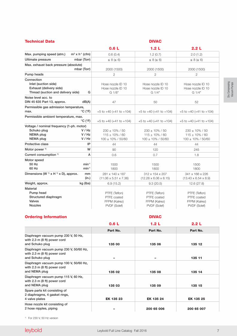
Ordering Information
Technical Data DIVAC
0 .6 L 1 .2 L 2 .2 LMax . pumping speed (atm .) m3 x h-1 (cfm)
Ultimate pressure mbar (Torr)
Max . exhaust back pressure (absolute) mbar (Torr)
Pump heads
Connection Inlet (suction side) Exhaust (delivery side) Thread (suction and delivery side) G
Noise level acc . to DIN 45 635 Part 13, approx . dB(A)
Permissible gas admission temperature, max . °C (°F)
Permissible ambient temperature, max . °C (°F)
Voltage / nominal frequency (1-ph . motor) Schuko plug V / Hz NEMA plug V / Hz NEMA plug V / Hz
Protective class IP
Motor power 1) W
Current consumption 1) A
Motor speed 50 Hz min-1 60 Hz min-1
Dimensions (W 1) x H 1) x D), approx . mm (in .)
Weight, approx . kg (lbs)
Material Pump head Structured diaphragm Valves Nozzles
0 .6 (0 .4) 1 .2 (0 .7) 2 .0 (1 .2)
≤ 8(≤ 6) ≤ 8(≤ 6) ≤ 8(≤ 6)
2000 (1500) 2000 (1500) 2000 (1500)
2 2 2
Hose nozzle ID 10 Hose nozzle ID 10 Hose nozzle ID 10 Hose nozzle ID 10 Hose nozzle ID 10 Hose nozzle ID 10 G 1/8" G 1/4" G 1/4"
47 50 52
+5 to +40 (+41 to +104) +5 to +40 (+41 to +104) +5 to +40 (+41 to +104)
+5 to +40 (+41 to +104) +5 to +40 (+41 to +104) +5 to +40 (+41 to +104)
230 ± 10% / 50 230 ± 10% / 50 230 ± 10% / 50 115 ± 10% / 60 115 ± 10% / 60 115 ± 10% / 60 100 ± 10% / 50/60 100 ± 10% / 50/60 100 ± 10% / 50/60
44 44 44
90 120 245
0 .6 0 .7 1 .8
1500 1500 1500 1800 1800 1800
281 x 140 x 187 312 x 154 x 207 341 x 166 x 226 (11 .06 x 5 .51 x 7 .36) (12 .28 x 6 .06 x 8 .15) (13 .43 x 6 .54 x 8 .9)
6 .9 (15 .2) 9 .3 (20 .5) 12 .6 (27 .8)
PTFE (Teflon) PTFE (Teflon) PTFE (Teflon) PTFE coated PTFE coated PTFE coated FFPM (Kalrez) FFPM (Kalrez) FFPM (Kalrez) PVDF (Solef) PVDF (Solef) PVDF (Solef)
Diaphragm vacuum pump 230 V, 50 Hz, with 2 .3 m (8 ft) power cord and Schuko plug
Diaphragm vacuum pump 230 V, 50/60 Hz, with 2 .3 m (8 ft) power cord and Schuko plug
Diaphragm vacuum pump 100 V, 50/60 Hz, with 2 .3 m (8 ft) power cord and NEMA plug
Diaphragm vacuum pump 115 V, 60 Hz, with 2 .3 m (8 ft) power cord and NEMA plug
Spare parts kit consisting of 2 diaphragms, 4 gasket rings, 4 valve plates
Hose nozzle kit consisting of 2 hose nipples, piping
1) For 230 V, 50 Hz version
DIVAC
0 .6 L 1 .2 L 2 .2 L
Part No . Part No . Part No .
135 00 135 06 135 12
– – 135 11
135 02 135 08 135 14
135 03 135 09 135 15
EK 135 23 EK 135 24 EK 135 25
– 200 65 006 200 65 007
DIVAC 1.4 HV3C
1013
00
Time
Pre
ssur
e
mbar
200
400
600
min4 8
Pressurembar
100
10
1
0,11 10 100 1000
m /h
Pum
ping
spe
ed
62 84
DIVAC 1.4 HV3C
50/60 Hz
3
leyboldLeybold Full Line Catalog Fall 20168
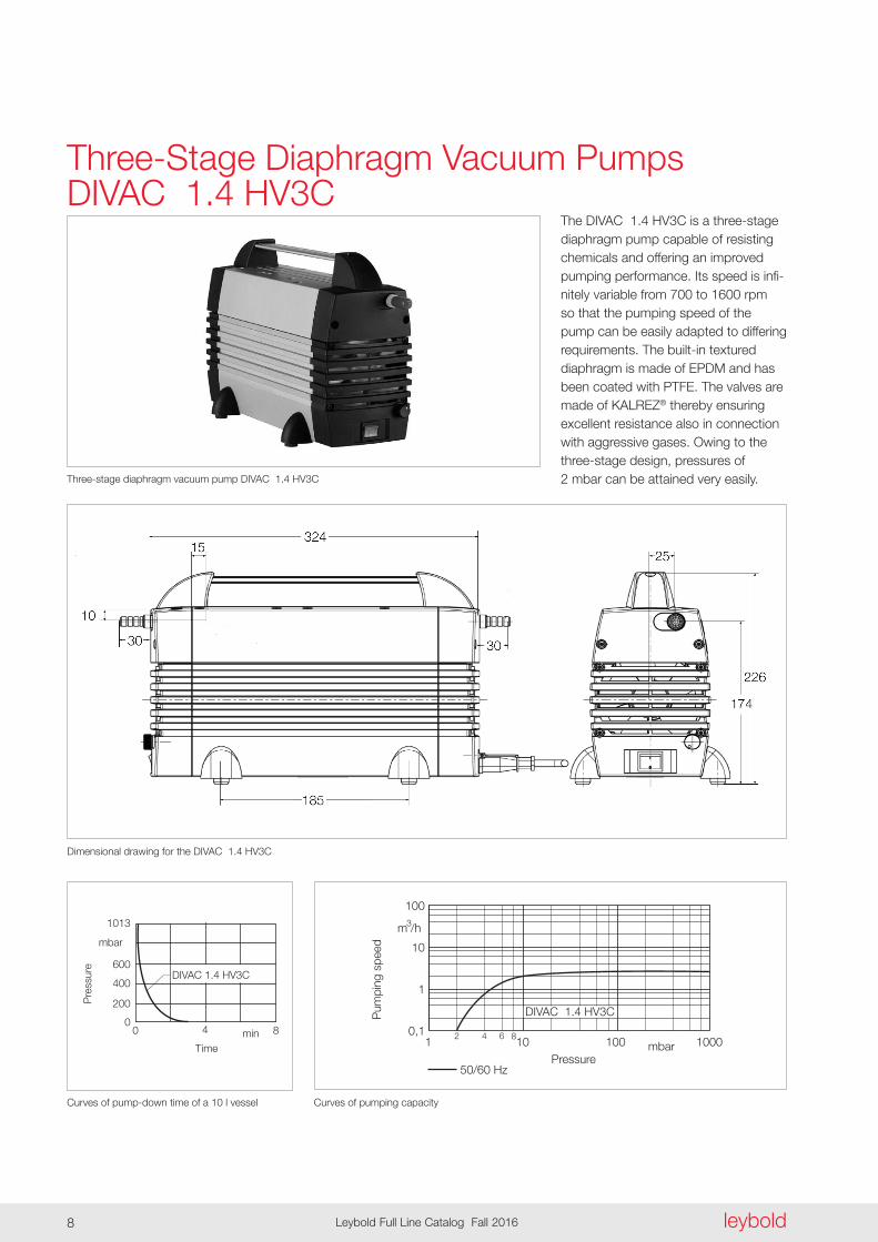
Three-Stage Diaphragm Vacuum Pumps DIVAC 1 .4 HV3C
The DIVAC 1 .4 HV3C is a three-stage diaphragm pump capable of resisting chemicals and offering an improved pumping performance . Its speed is infi-nitely variable from 700 to 1600 rpm so that the pumping speed of the pump can be easily adapted to differ ing requirements . The built-in textured diaphragm is made of EPDM and has been coated with PTFE . The valves are made of KALREZ® thereby ensuring excellent resistance also in connection with aggressive gases . Owing to the three-stage design, pressures of 2 mbar can be attained very easily .Three-stage diaphragm vacuum pump DIVAC 1 .4 HV3C
Dimensional drawing for the DIVAC 1 .4 HV3C
Curves of pump-down time of a 10 l vessel Curves of pumping capacity
Dry
Com
pres
sing
Vacu
um P
umps
leybold Leybold Full Line Catalog Fall 2016 9
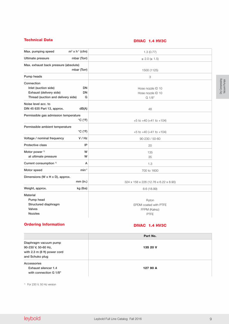
Technical Data DIVAC 1 .4 HV3C
Max . pumping speed m3 x h-1 (cfm)
Ultimate pressure mbar (Torr)
Max . exhaust back pressure (absolute)
mbar (Torr)
Pump heads
Connection
Inlet (suction side) DN
Exhaust (delivery side) DN
Thread (suction and delivery side) G
Noise level acc . to
DIN 45 635 Part 13, approx . dB(A)
Permissible gas admission temperature
°C (°F)
Permissible ambient temperature
°C (°F)
Voltage / nominal frequency V / Hz
Protective class IP
Motor power 1) W
at ultimate pressure W
Current consumption 1) A
Motor speed min-1
Dimensions (W x H x D), approx .
mm (in .)
Weight, approx . kg (lbs)
Material
Pump head
Structured diaphragm
Valves
Nozzles
1 .3 (0 .77)
≤ 2.0(≤ 1 .5)
1500 (1125)
3
Hose nozzle ID 10
Hose nozzle ID 10
G 1/8"
48
+5 to +40 (+41 to +104)
+5 to +40 (+41 to +104)
90-230 / 50-60
20
135
35
1 .3
700 to 1600
324 x 158 x 226 (12 .76 x 6 .22 x 8 .90)
8 .6 (18 .99)
Ryton
EPDM coated with PTFE
FFPM (Kalrez)
PTFE
Ordering Information
Diaphragm vacuum pump
90-230 V, 50-60 Hz,
with 2 .3 m (8 ft) power cord
and Schuko plug
Accessories
Exhaust silencer 1 .4
with connection G 1/8"
1) For 230 V, 50 Hz version
DIVAC 1 .4 HV3C
Part No .
135 20 V
127 90 A
leyboldLeybold Full Line Catalog Fall 201610
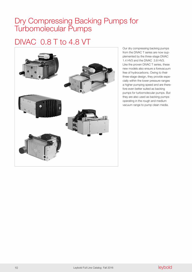
DIVAC 0 .8 T to 4 .8 VTOur dry compressing backing pumps from the DIVAC T series are now sup-plemented by the three-stage DIVAC 1 .4 HV3 and the DIVAC 3 .8 HV3 . Like the proven DIVAC T series, these new models also ensure a forevacuum free of hydrocarbons . Owing to their three-stage design, they provide espe-cially within the lower pressure ranges a higher pumping speed and are there-fore even better suited as backing pumps for turbomolecular pumps . But they are also used as backing pumps operating in the rough and medium vacuum range to pump clean media .
Dry Compressing Backing Pumps for Turbomolecular Pumps

Structured diaphragm, bottom side
Closed surface
Sealing rim
Structured diaphragm, sectional view
Dry
Com
pres
sing
Vacu
um P
umps
leybold Leybold Full Line Catalog Fall 2016 11
The structured diaphragm with its seal-ed surface provides the basis for a long service life and a low base pressure .
Diaphragm pump with structured diaphragm
Advantages to the User
- Dry compressing, free of oil and hydro-carbons
- Matched to the turbomolecular pumps from Leybold (SL 80 to TURBOVAC 450i)
- Low ultimate pressure
- ISO-KF flange at the intake port
- Fully equipped with cable, switch (ON/OFF) and plug
- Better performance and smaller size through the use of structured diaphragms
- Low vibration levels through dynamic mass balancing (in VT pumps)
- Lower maintenance costs and long maintenance intervals through the use of high-quality and well-proven components
- Simple maintenance
- Favourable price-to-performance ratio
- Can be operated in any position
Typical Applications
- Backing pump for wide pressure range turbomolecular pumps
- Mass spectrometers
- Medical equipment
- Analyzes
- For laboratory applications also with corrosive media
- General use for rough and fine vacuum applications

Pum
pin
g S
peed
Pum
pin
g S
peed
leyboldLeybold Full Line Catalog Fall 201612
DIVAC 0 .8 T DIVAC 0 .8 LT
DIVAC 0 .8 T and 0 .8 LT
Dimensional drawing for the DIVAC 0 .8 T Dimensional drawing for the DIVAC 0 .8 LT
Pumping speed curve of the DIVAC 0 .8 T Pumping speed curve of the DIVAC 0 .8 LT
Dry
Com
pres
sing
Vacu
um P
umps
leybold Leybold Full Line Catalog Fall 2016 13
Ordering Information
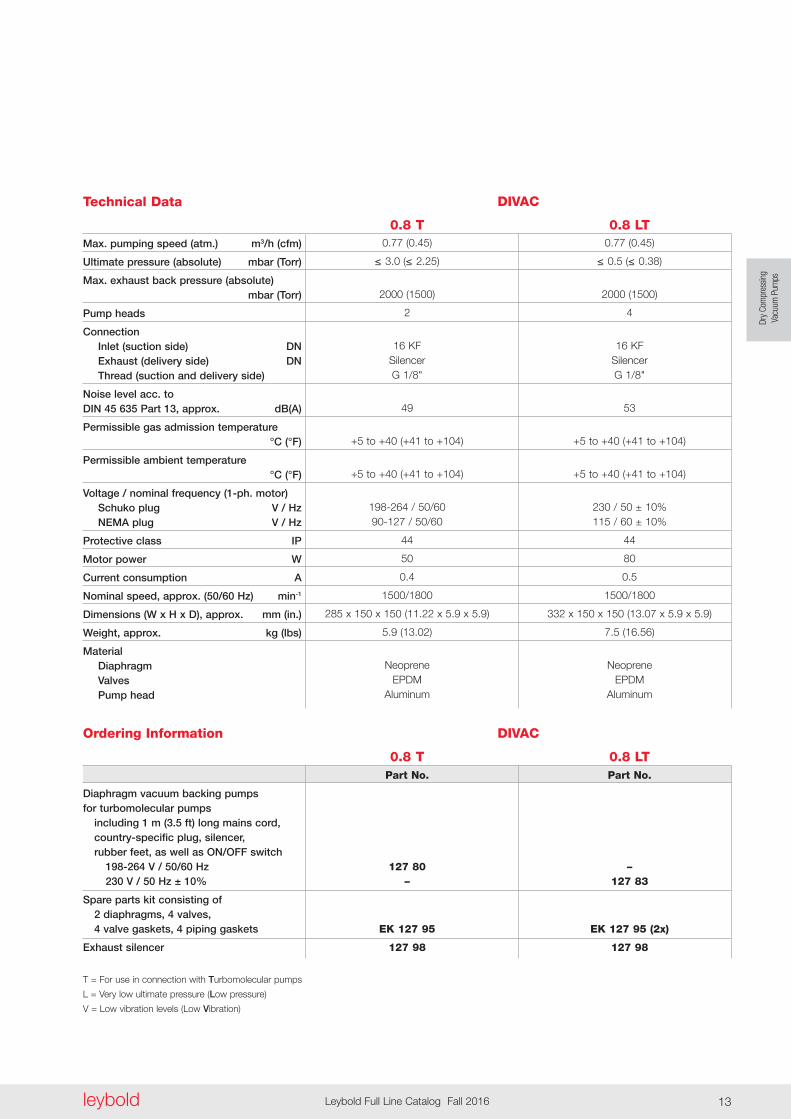
Technical Data DIVAC
0 .8 T 0 .8 LTMax . pumping speed (atm .) m3/h (cfm)
Ultimate pressure (absolute) mbar (Torr)
Max . exhaust back pressure (absolute) mbar (Torr)
Pump heads
Connection Inlet (suction side) DN Exhaust (delivery side) DN Thread (suction and delivery side)
Noise level acc . to DIN 45 635 Part 13, approx . dB(A)
Permissible gas admission temperature °C (°F)
Permissible ambient temperature °C (°F)
Voltage / nominal frequency (1-ph . motor) Schuko plug V / Hz NEMA plug V / Hz
Protective class IP
Motor power W
Current consumption A
Nominal speed, approx . (50/60 Hz) min-1
Dimensions (W x H x D), approx . mm (in .)
Weight, approx . kg (lbs)
Material Diaphragm Valves Pump head
0 .77 (0 .45) 0 .77 (0 .45)
≤ 3.0(≤ 2.25) ≤ 0.5(≤ 0 .38)
2000 (1500) 2000 (1500)
2 4
16 KF 16 KF Silencer Silencer G 1/8" G 1/8"
49 53
+5 to +40 (+41 to +104) +5 to +40 (+41 to +104)
+5 to +40 (+41 to +104) +5 to +40 (+41 to +104)
198-264 / 50/60 230 / 50 ± 10% 90-127 / 50/60 115 / 60 ± 10%
44 44
50 80
0 .4 0 .5
1500/1800 1500/1800
285 x 150 x 150 (11 .22 x 5 .9 x 5 .9) 332 x 150 x 150 (13 .07 x 5 .9 x 5 .9)
5 .9 (13 .02) 7 .5 (16 .56)
Neoprene Neoprene EPDM EPDM Aluminum Aluminum
Diaphragm vacuum backing pumps for turbomolecular pumps including 1 m (3 .5 ft) long mains cord, country-specific plug, silencer, rubber feet, as well as ON/OFF switch 198-264 V / 50/60 Hz 230 V / 50 Hz ± 10%
Spare parts kit consisting of 2 diaphragms, 4 valves, 4 valve gaskets, 4 piping gaskets
Exhaust silencer
T = For use in connection with Turbomolecular pumps
L = Very low ultimate pressure (Low pressure)
V = Low vibration levels (Low Vibration)
DIVAC
0 .8 T 0 .8 LT Part No . Part No .
127 80 – – 127 83
EK 127 95 EK 127 95 (2x)
127 98 127 98

Pressurembar
100
10
1
0,11 10 100 1000
m /h
Pum
ping
spe
ed
62 84
DIVAC 1.4 HV3
- 50/60 Hz
3
Pressurembar
100
10
1
0,10,1 1 10 100
m3 / h
Pum
ping
Spe
ed
62 84
DIVAC 3.8 HV3
- 50 Hz- 60 Hz
leyboldLeybold Full Line Catalog Fall 201614
DIVAC 1 .4 HV3 and 3 .8 HV3
Dimensional drawing for the DIVAC 1 .4 HV3 Dimensional drawing for the DIVAC 3 .8 HV3
Pumping speed curve of the DIVAC 1 .4 HV3 Pumping speed curve of the DIVAC 3 .8 HV3
DIVAC 1 .4 HV3
The three-stage DIVAC 1 .4 HV3 and the DIVAC 3 .8 HV3 provide especially in the lower pressure range a higher pumping speed compared to conven-tional diaphragm pumps . At the same time they are capable of attaining ultimate pressures below 2 mbar (1 .5 Torr) and are thus very well suited as backing pumps for turbomolecular pumps . Owing to their compact design they are also suited for installation with in pump systems .
DIVAC 3 .8 HV3

Dry
Com
pres
sing
Vacu
um P
umps
leybold Leybold Full Line Catalog Fall 2016 15
Ordering Information
Technical Data DIVAC
1 .4 HV3 3 .8 HV3Max . pumping speed 50 Hz m3/h (cfm) 60 Hz m3/h (cfm)
Ultimate pressure mbar (Torr)
Max . exhaust back pressure (absolute) mbar (Torr)
Pump heads
Connection Inlet (suction side) Exhaust (delivery side) Thread (suction and delivery side)
Noise level acc . to DIN 45 635 Part 13, approx . dB(A)
Permissible gas admission temperature, max . °C (°F)
Permissible ambient temperature, max . °C (°F)
Voltage / nominal frequency (1-ph . motor) Schuko plug V / Hz NEMA plug V / Hz
Protective class IP
Motor power W at ultimate pressure W
Current consumption A
Nominal speed, approx . (50/60 Hz) min-1
Dimensions (W x H x D), approx . mm (in .)
Weight, approx . kg (lbs)
Material Pump head Structured diaphragm Valves Nozzles
1 .3 (0 .77) 3 .4 (2 .00) – 3 .8 (2 .24)
≤ 1.5(≤ 1.13) ≤ 1.0(≤ 0 .75)
1500 (1125) 1500 (1125)
3 3
Hose nozzle ID 9 Hose nozzle ID 10 Hose nozzle ID 9 Hose nozzle ID 10 G 1/8" G 1/4"
48 54
+5 to +40 (+41 to +104) +5 to +40 (+41 to +104)
+5 to +40 (+41 to +104) +5 to +40 (+41 to +104)
90-230 / 50-60 90-230 / 50-60 – 115 / 50-60
20 20
120 250 35 190
1 .3 1 .7
1500 1500/1800
324 x 158 x 226 (12 .76 x 6 .22 x 8 .90) 295 x 240 x 203 (11 .61 x 9 .45 x 7 .99)
10 .5 (23 .18) 18 .9 (41 .72)
Aluminum Aluminum EPDM EPDM EPDM EPDM PA PA
Diaphragm vacuum backing pumps for turbomolecular pumps including 1 m (3 .5 ft) long mains cord, country-specific plug, silencer, rubber feet, as well as ON/OFF switch 90-230 V / 50-60 Hz 230 V / 50-60 Hz 115 V / 50-60 Hz
Exhaust silencer 1 .4 with connection G 1/8" 3 .8 with connection G 1/4"
Spare parts kit
DIVAC
1 .4 HV3 3 .8 HV3 Part No . Part No .
127 90 V – - 127 95 V - 127 96 V
127 90 A – – 127 95 A
EK057456 EK12768
Pum
pin
g S
peed
leyboldLeybold Full Line Catalog Fall 201616
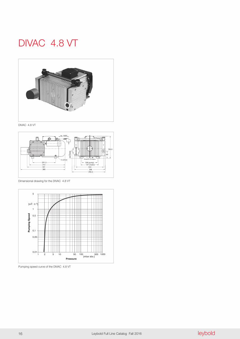
DIVAC 4 .8 VT
DIVAC 4 .8 VT
Dimensional drawing for the DIVAC 4 .8 VT
Pumping speed curve of the DIVAC 4 .8 VT

Dry
Com
pres
sing
Vacu
um P
umps
leybold Leybold Full Line Catalog Fall 2016 17
Ordering Information
Technical Data DIVAC 4 .8 VT
Max . pumping speed (atm .) m3/h (cfm)
Ultimate pressure (absolute) mbar (Torr)
Max . exhaust back pressure (absolute) mbar (Torr)
Pump heads
Connection Inlet (suction side) DN Exhaust (delivery side) DN Thread (suction and delivery side) G
Noise level acc . to DIN 45 635 Part 13, approx . dB(A)
Permissible gas admission temperature, max . °C (°F)
Permissible ambient temperature, max . °C (°F)
Voltage / nominal frequency (1-ph . motor) Schuko plug V / Hz NEMA plug V / Hz
Protective class IP
Motor power W
Current consumption A
Nominal speed, approx . (50 Hz) min-1
Dimensions (W x H x D), approx . mm (in .)
Weight, approx . kg (lbs)
Material Diaphragm Valves Pump head
4 .8 (2 .83)
≤ 2(≤ 1 .5)
2000 (1500)
2
16 KF
Silencer G 3/8"
55
+5 to +40 (+41 to +104)
+5 to +40 (+41 to +104)
230 / 50 ± 10% 115 / 60 ± 10%
54
350
2 .6
1500
324 x 273 x 220 (12 .76 x 10 .75 x 8 .66)
18 .0 (39 .74)
EPDM Viton
Aluminum
Diaphragm vacuum backing pumps for turbomolecular pumps including 1 m (3 .5 ft) long mains cord, country-specific plug, silencer, rubber feet, as well as ON/OFF switch 230 V / 50 Hz ± 10%
Spare parts kit consisting of 2 diaphragms, 4 valves, 4 valve gaskets, 4 piping gaskets
Exhaust silencer
T = For use in connection with Turbomolecular pumps L = Very low ultimate pressure (Low pressure) V = Low vibration levels (Low Vibration)
DIVAC 4 .8 VT
Part No .
127 92
EK 127 97
127 94

leyboldLeybold Full Line Catalog Fall 201618
General
Applications and Accessoriesfor SCROLLVAC Pumps
Electron beam melting
Lasers
Leak detection systems
Accelerators / Synchrotrons
Surface analysis instruments
Scanning electron microscopy
Loadlock
Spectroscopy
Lamps manufacture
As backing pump for turbomolecular pump systems
Applications
Pumps
SC 15
D
n n n n
n n n n
n n
n n n n
n
n n n n
n n n
n
n n n n
n n n n
SC 60
D
SC 5 D
SC 30
D

1
10
100
0.1
mbar0.01 0.10.001 1 10 1000100
Inlet Pressure
Pum
ping
Spe
ed
60 Hz50 Hz
SC 60 D
SC 30 D
SC 15 D SC 5 D
cfm
100
50
10
5
0.01
500
10-3 10-2 10-1 1 10 Torr 750100
m /h3
Dry
Com
pres
sing
Vacu
um P
umps
leybold Leybold Full Line Catalog Fall 2016 19
Oil-free Scroll Vacuum PumpsSCROLLVAC SC 5 to SC 60 D
In 1905 the principle of the scroll com-pressor was developed by the French-man Leon Creux . The scroll pump is now being used as an oil-free vacuum pump . Every scroll pump consists of two Archimedes spirals engaging each other with an offset of 180° . Thus se v e ral crescent-shaped pockets of dif fer ing sizes are created . By means of an eccentric drive, a second spiral is made to orbit about a fixed spiral, thus reducing the volume of the pockets and compressing gases from the out side towards the inside thereby pump ing the gases . Important to the quality of a scroll pump is that precise manufacturing tolerances are maintained and that suitable materials are selected .
Maintenance Intervals
In order to maintain the performance of the pump, a standard maintenance is required after a certain number of op er-ating hours .
For this we are offering complete main-tenance kits
- Small maintenance kit (Minor Kit) after 8,000 h or at latest after an operating time of 12 months
- Large maintenance kit (Major Kit) after 16,000 hours or at latest after an operating time of 24 months
Warranty
Upon signing a warranty contract, we will grant a two-year warranty for faulty material when complying with the re quired maintenance intervals .
Excluded are wearing parts as well as well wear due to the process .
Scroll vacuum pump SCROLLVAC, from left to right: SC 60 D, SC 30 D, SC 15 D, SC 5 D
Typical Applications
- Electron beam welding
- Lasers
- Leak detection systems
- Accelerators / synchrontrons
- Surface analysis instruments
- Scanning electron microscopes
- Load lock
- Spectroscopy
- Lamp manufacturing
- As a backing pump for turbomolecular pump systems
Advantage for the User
- Absolutely oil-free
- High effective pumping speed
- Low ultimate pressure
- Low noise level
- Low vibration operation
- Atmospheric inlet pressure allowable
- Low weight
- Air cooling
- Low power consumption
- Integrated operating hours counter
Products
Pumping speed curves for the scroll vacuum pumps SCROLLVAC SC - D

b1 b2
h
b
l1
l2 l3
l
Purge gas connection 1/8
3 phase 1 phase
b1
h
l l
b
h2
l6 l6l2
l4l4l7 l7 l7
l7
l5l5
b3b3
4x d 4x d
l2 l3
l1 l1
l3
h1
Purge gas connection 1/8
b3
l5l4
3 phase 1 phase
h 1h 2
h
b
b 1
l 1
l 6
l
l 2 l 3
l
l 1
l 2 l 3
b3 b3
l 4l 4
l 5l 5
l 7l 7l 7
l 7 4x d 4x d
l 6
4x d
leyboldLeybold Full Line Catalog Fall 201620
Dimensional drawing for the scroll vacuum pump SCROLLVAC SC 5 D (above) and SC 15 D (below)
Type b b1 b2 b3 d h h1 h2 l l1 l2 l3 l4 l5 l6 l7
SC 05 D mm 180 91 123 154 7 225 – – 308 85 90 140 104 112 – – in . 7 .09 3 .58 4 .84 6 .06 0 .28 8 .86 – – 12 .13 3 .35 3 .54 5 .51 40 .95 4 .41 – – SC 15 D mm 180 222 – 136 11 336 38 73 .5 400 1) 96 101 170 121 130 52 40 in . 7 .09 8 .74 – 5 .35 0 .43 13 .23 1 .50 2 .89 15 .75 1) 3 .78 3 .98 6 .69 4 .76 5 .12 2 .05 1 .58
1) 370 (14 .57 in .) for 3~ version
3 phase 1 phase
b2
b5
h5h4
h3
h1
h2
b6
b4
b3
b1
l1 l1 l2
l3 l4 l4
l2
b
h h
l l
b2
l3
h1
Purge gas connection 1/8
M10
l
h
h 1
l1
l4l3
b2
h2
b1b
b3
h3
M10
Purge gas connection 1/8
Dry
Com
pres
sing
Vacu
um P
umps
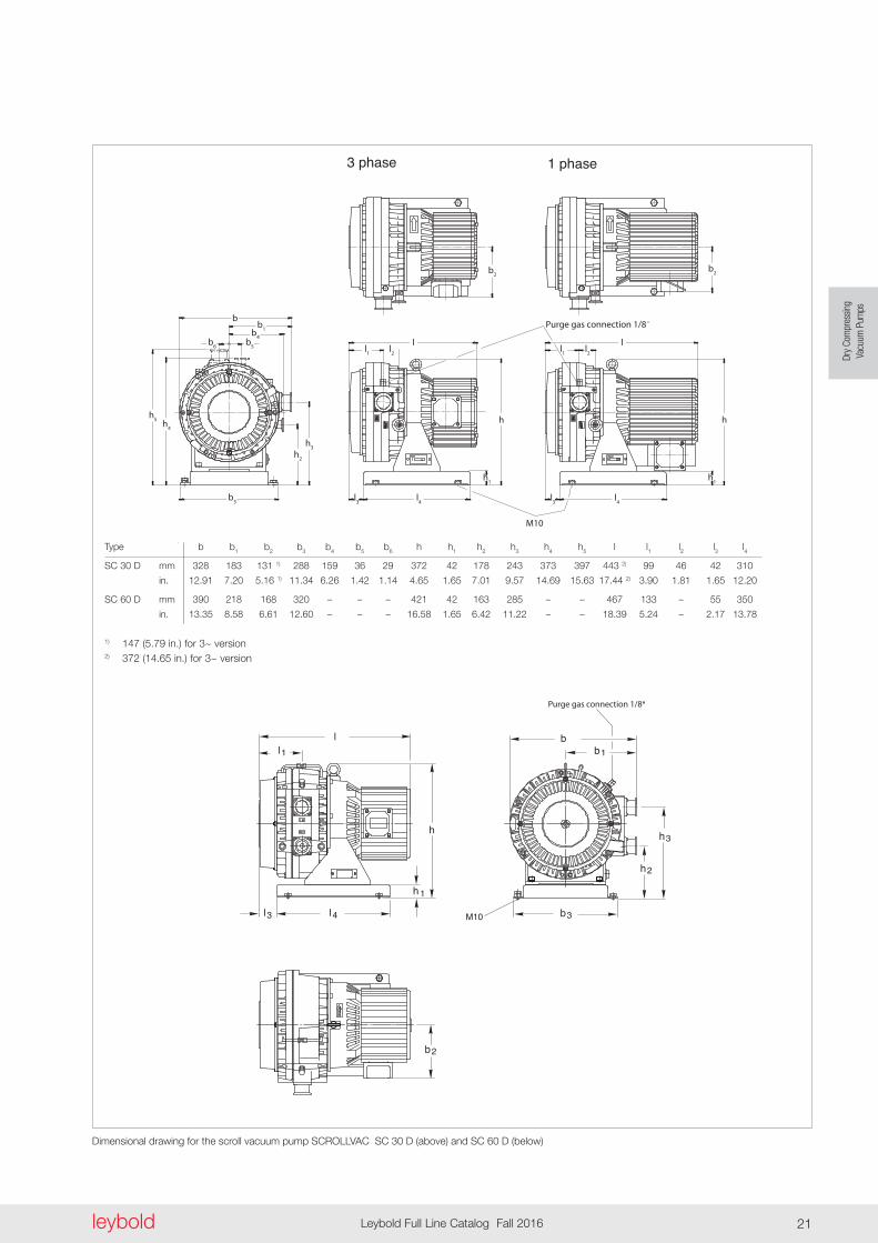
leybold Leybold Full Line Catalog Fall 2016 21
Dimensional drawing for the scroll vacuum pump SCROLLVAC SC 30 D (above) and SC 60 D (below)
Type b b1 b2 b3 b4 b5 b6 h h1 h2 h3 h4 h5 l l1 l2 l3 l4
SC 30 D mm 328 183 131 1) 288 159 36 29 372 42 178 243 373 397 443 2) 99 46 42 310
in . 12 .91 7 .20 5 .16 1) 11 .34 6 .26 1 .42 1 .14 4 .65 1 .65 7 .01 9 .57 14 .69 15 .63 17 .44 2) 3 .90 1 .81 1 .65 12 .20
SC 60 D mm 390 218 168 320 – – – 421 42 163 285 – – 467 133 – 55 350
in . 13 .35 8 .58 6 .61 12 .60 – – – 16 .58 1 .65 6 .42 11 .22 – – 18 .39 5 .24 – 2 .17 13 .78
1) 147 (5 .79 in .) for 3~ version2) 372 (14 .65 in .) for 3~ version
leyboldLeybold Full Line Catalog Fall 201622
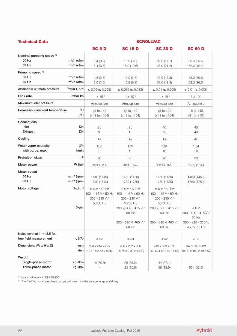
Technical Data SCROLLVAC
SC 5 D SC 15 D SC 30 D SC 60 D
Nominal pumping speed 1)
50 Hz m3/h (cfm)
60 Hz m3/h (cfm)
Pumping speed 1)
50 Hz m3/h (cfm)
60 Hz m3/h (cfm)
Attainable ultimate pressure mbar (Torr)
Leak rate mbar l/s
Maximum inlet pressure
Permissible ambient temperature °C
(°F)
Connections
Inlet DN
Exhaust DN
Cooling
Water vapor capacity g/h
with purge, max . l/min
Protection class IP
Motor power W (hp)
Motor speed
50 Hz min-1 (rpm)
60 Hz min-1 (rpm)
Motor voltage 1-ph . 2)
3-ph .
Noise level at 1 m (3 .5 ft),
free field measurement dB(A)
Dimensions (W x H x D) mm
(in .)
Weight
Single-phase motor kg (lbs)
Three-phase motor kg (lbs)
1) In accordance with DIN 28 4002) The Part No . for single-phase pumps will determine the voltage range at delivery
5 .4 (3 .2) 15 .0 (8 .8) 30 .0 (17 .7) 60 .0 (35 .4)
6 .4 (3 .8) 18 .0 (10 .6) 36 .0 (21 .2) 72 .0 (42 .4)
4 .8 (2 .8) 13 .0 (7 .7) 26 .0 (13 .3) 52 .0 (30 .6)
6 .0 (3 .5) 15 .5 (9 .1) 31 .0 (18 .3) 62 .0 (36 .5)
≤ 0.05(≤ 0.038) ≤ 0.016(≤ 0.012) ≤ 0.01(≤ 0.008) ≤ 0.01(≤ 0 .008)
1 x 10⁻⁶ 1 x 10⁻⁶ 1 x 10⁻⁶ 1 x 10⁻⁴
Atmosphere Atmosphere Atmosphere Atmosphere
+5 to +40 +5 to +40 +5 to +40 +5 to +40
(+41 to +104) (+41 to +104) (+41 to +104) (+41 to +104)
25 25 40 40
16 16 25 40
Air Air Air Air
0 .2 1 .04 1 .04 1 .04
9 10 10 10
20 20 20 20
150 (0 .20) 400 (0 .54) 600 (0 .82) 1400 (1 .90)
1440 (1440) 1450 (1450) 1450 (1450) 1460 (1460)
1740 (1740) 1730 (1730) 1730 (1730) 1760 (1760)
100 V / 50 Hz 100 V / 50 Hz 100 V / 50 Hz
100 - 115 V / 60 Hz 100 - 115 V / 60 Hz 100 - 115 V / 60 Hz
200 - 230 V / 200 - 230 V / 200 - 230 V /
50/60 Hz 50/60 Hz 50/60 Hz
200 V, 380 - 415 V / 200 V, 380 - 415 V / 200 V,
50 Hz 50 Hz 380 - 400 - 415 V /
50 Hz
200 - 380 V, 460 V / 200 - 380 V, 460 V / 200 - 220 - 230 V,
60 Hz 60 Hz 460 V, 60 Hz
≤ 52 ≤ 58 ≤ 62 ≤ 67
308 x 214 x 225 400 x 252 x 336 443 x 328 x 372 467 x 390 x 421
(12 .13 x 8 .43 x 8 .86) (15 .75 x 9 .92 x 13 .23) (17 .44 x 12 .91 x 14 .65) (18 .39 x 15 .35 x16 .57)
14 (30 .9) 25 (55 .2) 44 (97 .1) –
– 23 (50 .8) 38 (83 .9) 60 (132 .5)

Dry
Com
pres
sing
Vacu
um P
umps
leybold Leybold Full Line Catalog Fall 2016 23
Ordering Information SCROLLVAC
SC 5 D SC 15 D SC 30 D SC 60 D
Oil-free scroll vacuum pump
Single-phase motor, with cable and plug
Europe (Schuko plug, 230 V)
US / Japan (NEMA plug, 115 V)
Three-phase motor, without cable
Maintenance kits
Small maintenance kit
(after 8,000 h) Minor Kit
Large maintenance kit
(after 16,000 h) Major Kit
Tool kit SC 5/15/30/60 D
Scroll profile gasket (Tip Seal)
Shaft installation kit (Pin Crank Kit)
Part No . Part No . Part No . Part No .
133 000 133 001 133 002 –
133 100 133 101 133 102 –
– 133 003 133 004 133 008
EK 870000496 EK 870000497 EK 870000498 EK 870000519
EK 870000499 EK 870000500 EK 870000501 EK 870000520
EK 870000502 EK 870000503 EK 870000503 EK 870000521
E 870000510 E 870000511 E 870000512 E 870000522
EK 870000507 EK 870000508 EK 870000509 EK 870000523

Notes
leyboldLeybold Full Line Catalog Fall 201624

Dry
Com
pres
sing
Vacu
um P
umps
leybold Leybold Full Line Catalog Fall 2016 25
Applications for LEYVAC Pumps
Process industry
Industrial furnaces n n n n n n n n n
Degassing n n n n n n n n n
Charging n n n n n n n n n
Casting n n n n n n n n n
Drying processes in general n n n n n n
Freeze drying n n n n n n n n n
Packaging n n n n n n n n n
Coating
CVD coating n n n n n n n n n
Plasma coating n n n n n n n n n
Glass coating n n n n n n n n n
Web coating n n n n n n n n n
Solar
CVD/PECVD n n n n n n n n n
Crystal pulling and casting n n n n n n n n n
Support functions
Regeneration of cryo pumps n n n n n n n n n
Forevacuum pumps for Turbomolecular pumps n n n n n n n n n
Dry c
ompre
ssing
va
cuum
pum
ps
Applications
General
LEYVA
C LV 8
0
LEYVA
C LV 2
50 C
C
LEYVA
C LV 2
50 C
LEYVA
C LV 2
50
LEYVA
C LV 1
40 C
C
LEYVA
C LV 1
40 C
LEYVA
C LV 8
0 C
LEYVA
C LV 8
0 CC
LEYVA
C LV 1
40

leyboldLeybold Full Line Catalog Fall 201626
Advantages to the User
- Dry pump technology
- No contact of the process gases with oil
- Shortest pumpdown times through high pumping speed for air already starting at atmospheric pressure
- Hermetically tight - No shaft seals - No oil leakage - Safe pumping of toxic gases
- High reliability - Long service intervals (up to 5 years) - High uptime - Robust and durable design
- One motor solution - Multi-voltage, dual frequency motor operable at 200 V - 460 V and 50/60 Hz
- Easy and modular - Direct coupling of roots booster pumps without frames for models RUVAC WH 700 and WA(U)/ WS(U) 251-1001
Typical Application
- Process industry - Industrial furnaces - Degassing - Charging - Casting - Drying processes - Freeze drying - Electron beam welding - Packaging
- Coating - PVD/CVD coating - Wear resistant coating - Optical coating - Web coating - Load locks/transfer chambers
- Solar - CVD/PECVD - Crystal pulling and casting
- Support functions - Regeneration of cryo pumps - Forevacuum pumps for turbomo- lecular pumps
Performance Details at a Glance
LEYVAC dry vacuum pumps provide optimized
- System uptime - Robust design based on the pro- ven RUVAC and DRYVAC techno- logy - Most effective cooling system - Thermal protection on board (for CC versions) - Tolerant to pressure shocks - Long intervals for bearing exchange
- Process safety - designed for harsh applications
- Performance data - High pumping speed already at high intake pressures - Good pumping speed also for lighter gases (with purge)
- Environmental properties - Low noise and low heat emission
- Price-to-performance ratio - Low investment costs - Small, price optimized pumping systems
General
Our LEYVAC dry vacuum pumps provide power combined with high performance .
This product line covers the pumping speed ranges from 80 to 300 m³/h and is especially suited to meet the special requirements of industrial processes and coating applications . LEYVAC pumps and system combina-tions are rugged, reliable and durable, ready to cope with harsh process requirements . The LEYVAC product line comprises the models LEYVAC LV 80, LV 140, LV 250 and their C or CC versions . The new LEYVAC 250 significantly expands the performance spectrum of this product range with excellent energy efficiency characteristics . The CC versions include an overtem-perature safety shutdown facility .
LEYVAC LV 80, 140 and 250
LEYVACExcellent efficiency in every respect

Dry
Com
pres
sing
Vacu
um P
umps
leybold Leybold Full Line Catalog Fall 2016 27
Pumping speed curves of the LEYVAC LV 80 (C/CC), LEYVAC LV 140 (C/CC) and LEYVAC LV 250 (C/CC)
0.0
1.0
2.0
3.0
4.0
5.0
0
25
50
75
100
0.001 0.01 0.1 1 10 100 [mbar]
[m/h
]
Pow
er C
ons
ump
tion
[kW
]
Pum
pin
g S
pee
d
60 Hz Pump Speed Air 50 Hz Pump Speed Air
50 Hz Power Air 60 Hz Power Air
Inlet Pressure
LEYVAC LV 80 (C/CC)
1000
0.0
1.0
2.0
3.0
4.0
5.0
6.0
7.0
0
25
50
75
100
125
150
0.001 0.01 0.1 1 10 100
Po
wer
Co
nsum
ptio
n [k
W]
Pum
pin
g S
pee
d [m
3/h
]
Inlet Pressure [mbar]
LEYVAC LV 140 (C/CC)
60 Hz Pump Speed Air 50 Hz Pump Speed Air
50 Hz Power Air 60 Hz Power Air
1000
0 0.001
300
200
100
250
150
50
1
60 Hz Pump Speed Air 50 Hz Pump Speed Air
50 Hz Power Air 60 Hz Power Air
Po
wer
Co
nsum
ptio
n [k
W]
Pum
pin
g S
pee
d [m
3/h
]
Inlet Pressure [mbar]
LEYVAC LV 250 (C/CC)
0.01 0.1 10 100 1000
14
2
8
12
10
6
4
0

leyboldLeybold Full Line Catalog Fall 201628
Nominal pumping speed without gas ballast at 50/60 Hz m3 x h-1 (cfm)Ultimate pressure with seal and rotor purge mbar (Torr)Power consumption at ultimate pressure and 50/60 Hz operation kW (hp)Weight, approx . LV . . . kg (lbs) LV . . . C/CC kg (lbs)Noise level 1) dB(A)Connection flange Intake DN Discharge DNMains voltage (± 10%) LV . . . V LV . . . C (with housing) V LV . . . CC (with housing and Temperature monitoring) VNominal power at 50/60 Hz kW (hp)Nominal current consumption 50/60 Hz at 400 V ACoolingCooling water temperature °C (°F)Min . cooling water throughput l/minWater vapor tolerance (with gas ballast) 080 slm 50/60 Hz mbar (Torr) 150 slm 50/60 Hz 2) mbar (Torr)Water vapor capacity (with gas ballast) 080 slm 50/60 Hz kg/h 150 slm 50/60 Hz 2) kg/hPermissible ambient temperature °C (°F)Protection class EN 60529 IPDimensions (W x H x D) LV . . . and LV . . . C mm (in .) LV . . . CC mm (in .)1) At ultimate pressure and with rigid exhaust line DIN EN ISO 21512) 2nd case: with 24 V gas ballast kit 115005A13 fitted to port 2, standard purge also opened
80/96 (47 .1/56 .5) 125/145 (73 .6/85 .3) 250/300 (147 .1/176 .6) 1 x 10⁻² (0 .75 x 10-2) 1 x 10⁻² (0 .75 x 10-2) 1 x 10⁻² (0 .75 x 10-2)
2 .9/3 .2 (3 .9/4 .3) 3 .9/4 .3 (5 .2/5 .8) 4 .2/4 .7 (5 .6/6 .3)
280 (617) 300 (661) 330 (728) 300 (661) 320 (705) 350 (772) < 65 < 65 < 72 63 ISO-K 63 ISO-K 63 ISO-K 40 ISO-KF 40 ISO-KF 40 ISO-KF
200 - 460 200 - 460 200 - 460 200 - 460 200 - 460 200 - 460
380 - 460 380 - 460 380 - 460 4 .1 (5 .5) 5 .5 (7 .4) 8 .0 (10 .7)
6 8 16 water/glycol water/glycol water/glycol +15 to +30 (+59 to +86) +15 to +30 (+59 to +86) +15 to +30 (+59 to +86) 3 3 3
20/30 125/160 -/- -/- -/- 30/37
1 .24/2 .3 11 .5/18 .0 -/- -/- -/- 6 .3/6 .5 +5 to +45 (+41 to +113) +5 to +45 (+41 to +113) +5 to +45 (+41 to +113) 54 54 54
814 x 375 x 550 895 x 400 x 567 1051 x 425 x 537 (32 .05 x 14 .76 x 21 .65) (35 .24 x 15 .75 x 22 .32) (41 .38 x 16 .73 x 21 .14) 984 x 375 x 550 1065 x 400 x 567 1224 x 425 x 537 (38 .74 x 14 .76 x 21 .65) (41 .93 x 15 .75 x 22 .32) (48 .19 x 16 .73 x 21 .14)
ProductsTechnical Data LEYVAC
LV 80 (C/CC) LV 140 (C/CC) LV 250 (C/CC)
b1
b
h
b2
l2l1l3
h1
h2
l
l4 l5
h3 h4 h5
l5
Type b b1 b2 h h1 h2 h3 h4 h5 l (CC version) l1 l2 l3 l4 l5LV 80 (C) mm 375 320 266 550 576 266 266 341 191 814 (984) 335 265 402 485 410 in . 14 .76 12 .60 10 .47 21 .65 22 .68 10 .47 10 .47 13 .43 7 .52 32 .05 (38 .74) 13 .19 10 .43 15 .83 19 .09 16 .14LV 140 (C) mm 400 350 285 567 597 257 257 332 182 895 (1065) 364 297 453 514 439 in . 15 .75 13 .78 11 .22 22 .32 23 .50 10 .12 10 .12 13 .07 7 .17 35 .24 (41 .93) 14 .33 11 .69 17 .84 20 .24 17 .28LV 250 (C) mm 425 375 285 537 570 230 230 305 155 1051 (1224) 512 420 464 662 587 in . 16 .73 14 .76 11 .22 21 .14 22 .44 9 .06 9 .06 12 .01 6 .01 41 .38 (48 .19) 20 .16 16 .54 18 .27 26 .06 21 .93
l4 l5
h3 h4 h5
l5l4 l5
h3 h4 h5
l5
Dimensional drawing for the LEYVAC LV 80/C and LV 140/C; below for exhaust connection
Dry
Com
pres
sing
Vacu
um P
umps
leybold Leybold Full Line Catalog Fall 2016 29
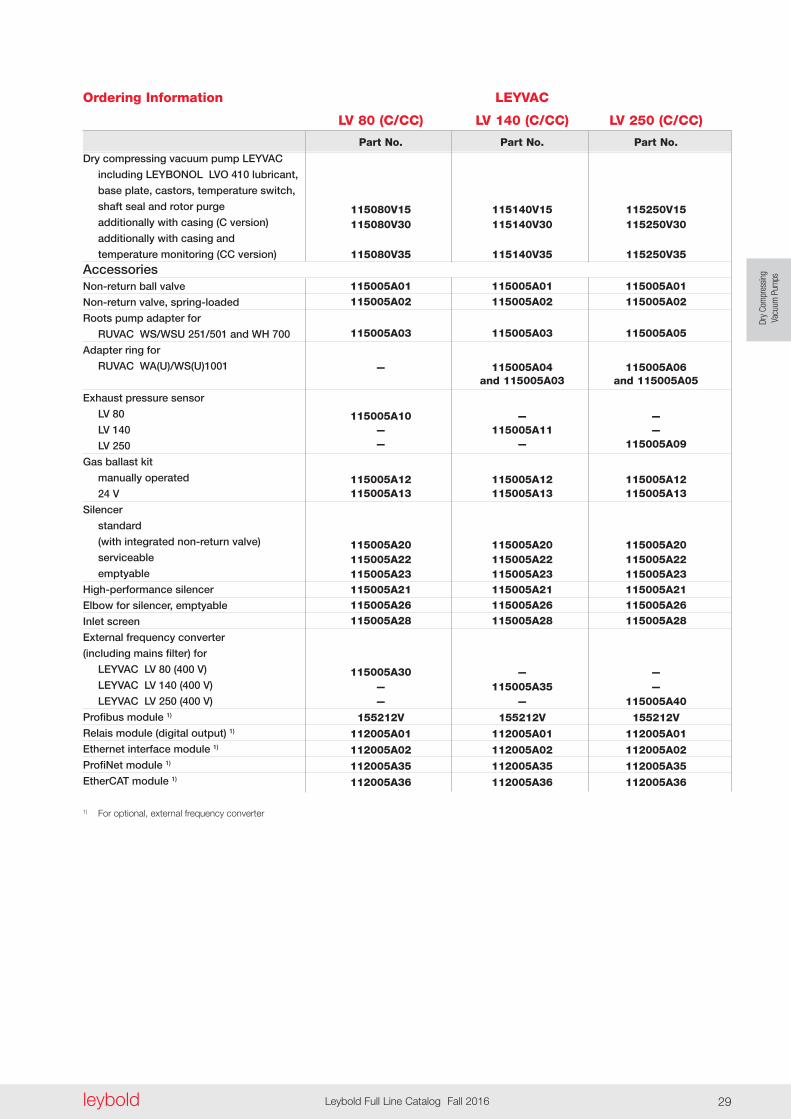
Ordering Information
Dry compressing vacuum pump LEYVAC
including LEYBONOL LVO 410 lubricant,
base plate, castors, temperature switch,
shaft seal and rotor purge
additionally with casing (C version)
additionally with casing and
temperature monitoring (CC version)
AccessoriesNon-return ball valve
Non-return valve, spring-loaded
Roots pump adapter for
RUVAC WS/WSU 251/501 and WH 700
Adapter ring for
RUVAC WA(U)/WS(U)1001
Exhaust pressure sensor
LV 80
LV 140
LV 250
Gas ballast kit
manually operated
24 V
Silencer
standard
(with integrated non-return valve)
serviceable
emptyable
High-performance silencer
Elbow for silencer, emptyable
Inlet screen
External frequency converter
(including mains filter) for
LEYVAC LV 80 (400 V)
LEYVAC LV 140 (400 V)
LEYVAC LV 250 (400 V)
Profibus module 1)
Relais module (digital output) 1)
Ethernet interface module 1)
ProfiNet module 1)
EtherCAT module 1)
1) For optional, external frequency converter
LEYVAC
LV 80 (C/CC) LV 140 (C/CC) LV 250 (C/CC)
Part No . Part No . Part No .
115080V15 115140V15 115250V15 115080V30 115140V30 115250V30 115080V35 115140V35 115250V35
115005A01 115005A01 115005A01 115005A02 115005A02 115005A02
115005A03 115005A03 115005A05
— 115005A04 115005A06 and 115005A03 and 115005A05
115005A10 — — — 115005A11 — — — 115005A09
115005A12 115005A12 115005A12 115005A13 115005A13 115005A13
115005A20 115005A20 115005A20 115005A22 115005A22 115005A22 115005A23 115005A23 115005A23 115005A21 115005A21 115005A21 115005A26 115005A26 115005A26 115005A28 115005A28 115005A28
115005A30 — — — 115005A35 — — — 115005A40
155212V 155212V 155212V
112005A01 112005A01 112005A01
112005A02 112005A02 112005A02
112005A35 112005A35 112005A35
112005A36 112005A36 112005A36

Notes
leyboldLeybold Full Line Catalog Fall 201630
Dry
Com
pres
sing
Vacu
um P
umps
leybold Leybold Full Line Catalog Fall 2016 31
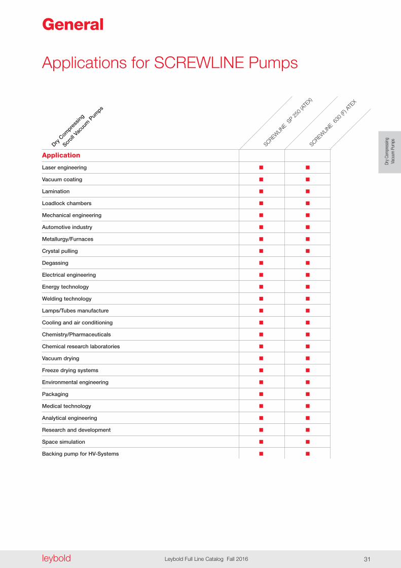
Applications for SCREWLINE Pumps
General
Laser engineering n n
Vacuum coating n n
Lamination n n
Loadlock chambers n n
Mechanical engineering n n
Automotive industry n n
Metallurgy/Furnaces n n
Crystal pulling n n
Degassing n n
Electrical engineering n n
Energy technology n n
Welding technology n n
Lamps/Tubes manufacture n n
Cooling and air conditioning n n
Chemistry/Pharmaceuticals n n
Chemical research laboratories n n
Vacuum drying n n
Freeze drying systems n n
Environmental engineering n n
Packaging n n
Medical technology n n
Analytical engineering n n
Research and development n n
Space simulation n n
Backing pump for HV-Systems n n
Dry C
ompre
ssing
Scr
oll Vac
uum
Pum
ps
Application
SCREWLIN
E 630
(F) A
TEX
SCREWLIN
E SP 2
50 (A
TEX)

leyboldLeybold Full Line Catalog Fall 201632
Principle of Operation
Screw Vacuum Pumps are dry com-pressing backing pumps, the operation of which is based on the screw princi-ple . The pumping chamber of the pump is formed by two synchronised positive displacement rotors and the housing enclosing these . Since the rotors rotate in opposite directions, the chambers move steadily from the in take to the exhaust side of the pumps thereby resulting in a smooth pumping action (see figure below) . Since with a single Screw Vacuum Pump rotor pair a multi stage compression process is implemented, the component count in the pumping path is very low . In this way maintenance and servicing work is much simplified .
Properties
The direct pumping path without multiple deflections for the medium make the Screw Vacuum Pumps highly insen sitive to foreign materials . This ensures a high uptime in industrial processes .
The two non-contacting shaft-seals are practically wear-free, which allows for very long maintenance intervals . For standard applications no purge gas is required . However, a purge gas sup-ply can be connected as an option to purge the seals, should the application process require this .
Because of the cantilevered bearing arrangement for the Screw Vacuum Pump rotors, a potential source of fail-ure (i .e . a bearing on the intake side) is entirely eliminated . On the one hand, no lubricants from the bearings can enter into the vacuum process, and the other hand also an impairment of the bearing by aggressive process media can be excluded .
A further benefit of the cantilevered bearing arrangement is the easy
accessibility of the pump chamber . This innovative design feature allows the removal of the pump housing with out time- consuming and costly disassem-bly of the bearings . Thus on-site clean-ing of all surfaces in contact with the medium is possible . In particular, if the processes involved considerable amounts of contaminants this is a sig nificant advantage which ensures a long uptime .
The low exhaust temperature is an important advantage of the Screw Vacuum Pumps . Owing to the design of the screw rotors, a temperature of maximum 100 °C (212 °F) is attained inside the pump . Thus deposits of many substances are avoided which react at high temperatures . This makes the pump unique and many customers, above all from the field of coat ing, value this highly . Should deposits form in spite of this, then the easy to disassemble housing facilitates rapid cleaning .
Pump chamber housing
Direction of pumping action
Direction of rotation
Rotors
Principle of operation of the SCREWLINE Line
General
The Screw Vacuum Pumps SCREWLINE were developed in view of the special requirements of industrial applications . The innovative design allows these pumps to be used when-ever reliable, compact and low mainte-nance vacuum solutions are required .
Pump system Screw Vacuum Pump SCREWLINE SP 630 with RUVAC WAU 2001
Dry
Com
pres
sing
Vacu
um P
umps
leybold Leybold Full Line Catalog Fall 2016 33
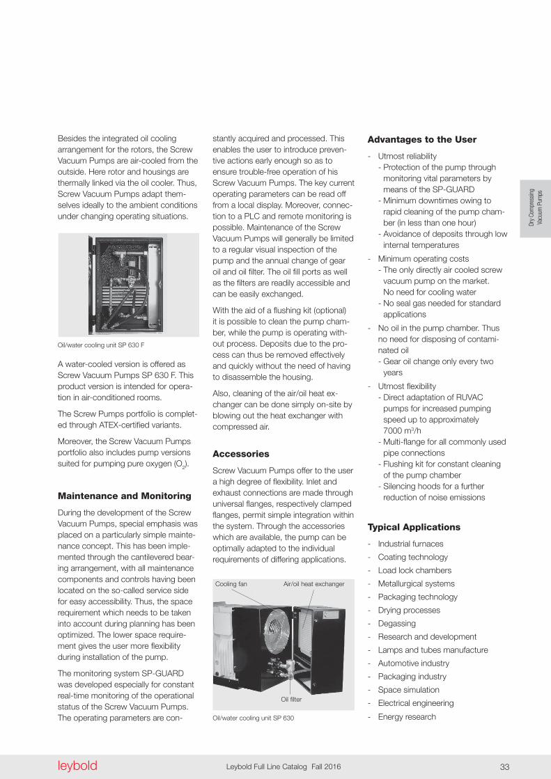
Oil/water cooling unit SP 630 F
Besides the integrated oil cooling arrangement for the rotors, the Screw Vacuum Pumps are air-cooled from the outside . Here rotor and housings are thermally linked via the oil cooler . Thus, Screw Vacuum Pumps adapt them-selves ideally to the am bient conditions under changing operating situations .
stantly acquired and processed . This enables the user to introduce preven- tive actions early enough so as to ensure trouble-free operation of his Screw Vacuum Pumps . The key current operating parameters can be read off from a local display . Moreover, connec-tion to a PLC and remote monitoring is possible . Maintenance of the Screw Vacuum Pumps will generally be limited to a regular visual inspection of the pump and the annual change of gear oil and oil filter . The oil fill ports as well as the filters are readily accessible and can be easily exchanged .
With the aid of a flushing kit (optional) it is possible to clean the pump cham-ber, while the pump is operating with-out process . Deposits due to the pro-cess can thus be removed effectively and quickly without the need of having to disassemble the housing .
Also, cleaning of the air/oil heat ex-changer can be done simply on-site by blowing out the heat exchanger with compressed air .
Accessories
Screw Vacuum Pumps offer to the user a high degree of flexibility . Inlet and exhaust connections are made through universal flanges, respectively clamped flanges, permit simple integration within the system . Through the accessories which are available, the pump can be optimally adapted to the individual requirements of differing applications .
Advantages to the User
- Utmost reliability - Protection of the pump through monitoring vital parameters by means of the SP-GUARD - Minimum downtimes owing to rapid cleaning of the pump cham- ber (in less than one hour) - Avoidance of deposits through low internal temperatures
- Minimum operating costs - The only directly air cooled screw vacuum pump on the market . No need for cooling water - No seal gas needed for standard applications
- No oil in the pump chamber . Thus no need for disposing of contami- nated oil - Gear oil change only every two years
- Utmost flexibility - Direct adaptation of RUVAC pumps for increased pumping speed up to approximately 7000 m3/h - Multi-flange for all commonly used pipe connections - Flushing kit for constant cleaning of the pump chamber - Silencing hoods for a further reduction of noise emissions
Typical Applications
- Industrial furnaces
- Coating technology
- Load lock chambers
- Metallurgical systems
- Packaging technology
- Drying processes
- Degassing
- Research and development
- Lamps and tubes manufacture
- Automotive industry
- Packaging industry
- Space simulation
- Electrical engineering
- Energy research
A water-cooled version is offered as Screw Vacuum Pumps SP 630 F . This product version is intended for opera-tion in air-conditioned rooms .
The Screw Pumps portfolio is complet-ed through ATEX-certified variants .
Moreover, the Screw Vacuum Pumps portfolio also includes pump versions suited for pumping pure oxygen (O2) .
Maintenance and Monitoring
During the development of the Screw Vacuum Pumps, special emphasis was placed on a particularly simple mainte-nance concept . This has been imple-mented through the cantilevered bear-ing arrangement, with all mainte nance components and controls having been located on the so-called service side for easy accessibility . Thus, the space requirement which needs to be taken into account during planning has been optimized . The lower space require-ment gives the user more flexibility during installation of the pump .
The monitoring system SP-GUARD was developed especially for constant real-time monitoring of the operational status of the Screw Vacuum Pumps . The operating parameters are con- Oil/water cooling unit SP 630
Air/oil heat exchangerCooling fan
Oil filter
a
h4
h1h
h 2
l 3l 2
l 1l
l 4
h 3
b 2b 3
b
b 1
a
> 900distance for maintenance
a
a
a
b 4
h 1
h 2
h 3
h 4
l
l 1
l 5l 6
h5
l 4 l 3
l 2
a 1
b 2
b
h
b 3
b 1
> 900distance for maintenance
l7
leyboldLeybold Full Line Catalog Fall 201634
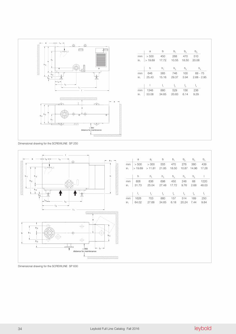
Dimensional drawing for the SCREWLINE SP 250
a b b1 b2 b3
mm > 500 450 268 470 510 in . > 19 .69 17 .72 10 .55 18 .50 20 .08
h h1 h2 h3 h4
mm 646 385 746 100 68 - 75 in . 25 .43 15 .16 29 .37 3 .94 2 .68 - 2 .95
l l1 l2 l3 l4
mm 1348 880 529 156 236 in . 53 .08 34 .65 20 .83 6 .14 9 .29
Dimensional drawing for the SCREWLINE SP 630
a a1 b b1 b2 b3 b4
mm > 500 > 300 555 470 276 380 439 in . > 19 .69 > 11 .81 21 .85 18 .50 10 .87 14 .96 17 .28
h h1 h2 h3 h4 h5 l
mm 806 636 698 450 248 68 1220 in . 31 .73 25 .04 27 .48 17 .72 9 .76 2 .68 48 .03
l1 l2 l3 l4 l5 l6 l7
mm 1626 703 880 157 514 189 250 in . 64 .02 27 .68 34 .65 6 .18 20 .24 7 .44 9 .84

Pressure mbar
0
100
200
300
400
P
um
pin
g S
pee
d
m3/h
10-3 10-2 10-1 100 101 102 103
SP 250 (50 Hz)
SP 250 (60 Hz)
10-1 1 10 Torr 75010-210-3
200
cfm
50
100
10-20
100
200
300
400
500
600
700
800
10-3 10-1 100 101 102 103
Pressure mbar
Pu
mp
ing
Sp
eed
m3/h
10-1 1 10 Torr 75010-210-3
400
cfm
50
100
Dry
Com
pres
sing
Vacu
um P
umps
leybold Leybold Full Line Catalog Fall 2016 35
Effective pumping speed of the SCREWLINE SP 250 for air, without gas ballast (50/60 Hz)
Effective pumping speed of the SCREWLINE SP 630 for air, without gas ballast
leyboldLeybold Full Line Catalog Fall 201636
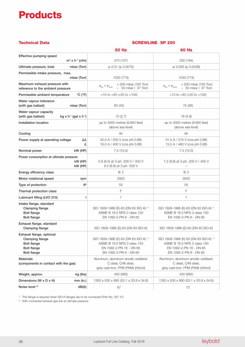
Technical Data SCREWLINE SP 250
50 Hz 60 HzEffective pumping speed m3 x h-1 (cfm)
Ultimate pressure, total mbar (Torr)
Permissible intake pressure, max . mbar (Torr)
Maximum exhaust pressure with reference to the ambient pressure
Permissible ambient temperature °C (°F)
Water vapour tolerance (with gas ballast) mbar (Torr)
Water vapour capacity (with gas ballast) kg x h-1 (gal x h-1)
Installation location
Cooling
Power supply at operating voltage ∆∆ ∆
Nominal power kW (HP)
Power consumption at ultimate pressure kW (HP) kW (HP)
Energy efficiency class
Motor rotational speed rpm
Type of protection IP
Thermal protection class
Lubricant filling (LVO 210) l
Intake flange, standard Clamping flange Bolt flange Bolt flange
Exhaust flange, standard Clamping flange
Exhaust flange, optional Clamping flange Bolt flange Bolt flange Bolt flange
Materials (components in contact with the gas)
Weight, approx . kg (lbs)
Dimensions (W x D x H) mm (in .)
Noise level 2) dB(A)
1) This flange is required when ISO-K flanges are to be connected (Part No . 267 47)2) With connected exhaust gas line at ultimate pressure
270 (157) 330 (194)
≤ 0.01(≤ 0.0075) ≤ 0.005(≤ 0 .0038)
1030 (773) 1030 (773) + 200 mbar (150 Torr) + 200 mbar (150 Torr) pex = pamb pex = pamb – 050 mbar (037 Torr) – 050 mbar (037 Torr)
+10 to +40 (+50 to +104) +10 to +40 (+50 to +104)
60 (45) 75 (56)
10 (2 .7) 18 (4 .9)
up to 3000 metres (9 .800 feet) up to 3000 metres (9 .800 feet) (above sea level) (above sea level)
Air Air
32 .0 A / 200 V (cos phi 0 .88) 31 .5 A / 210 V (cos phi 0 .88) 16 .0 A / 400 V (cos phi 0 .88) 15 .5 A / 460 V (cos phi 0 .88)
7 .5 (10 .0) 7 .5 (10 .0)
5 .9 (8 .0) at 3-ph . 200 V / 400 V 7 .2 (9 .8) at 3-ph . 200 V / 400 V 6 .5 (8 .8) at 3-ph . 500 V –
IE 2 IE 2
2920 3505
55 55
F F
7 7
ISO 1609-1986 (E)-63 (DN 63 ISO-K) 1) ISO 1609-1986 (E)-63 (DN 63 ISO-K) 1) ASME B 16 .5 NPS 3 class 150 ASME B 16 .5 NPS 3 class 150 EN 1092-2-PN 6 - DN 65 EN 1092-2-PN 6 - DN 65
ISO 1609-1986 (E)-63 (DN 63 ISO-K) ISO 1609-1986 (E)-63 (DN 63 ISO-K)
ISO 1609-1986 (E)-63 (DN 63 ISO-K) 1) ISO 1609-1986 (E)-63 (DN 63 ISO-K) 1) ASME B 16 .5 NPS 3 class 150 ASME B 16 .5 NPS 3 class 150 EN 1092-2-PN 16 - DN 65 EN 1092-2-PN 16 - DN 65 EN 1092-2-PN 6 - DN 65 EN 1092-2-PN 6 - DN 65
Aluminum, aluminum anodic oxidised, Aluminum, aluminum anodic oxidised, C steel, CrNi steel, C steel, CrNi steel, grey cast-iron, FPM (FKM) ((Viton)) grey cast-iron, FPM (FKM) ((Viton))
450 (992) 450 (992)
1350 x 530 x 880 (53 .1 x 20 .9 x 34 .6) 1350 x 530 x 880 (53 .1 x 20 .9 x 34 .6)
67 72
Products
Dry
Com
pres
sing
Vacu
um P
umps
leybold Leybold Full Line Catalog Fall 2016 37
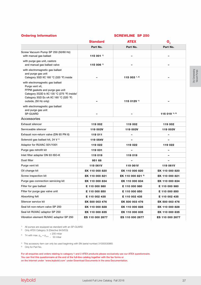
Ordering Information
Screw Vacuum Pump SP 250 (50/60 Hz) with manual gas ballast
with purge gas unit, castors and manual gas ballast valve
with electromagnetic gas ballast and purge gas unit Category 3GD IIC 160 °C (320 °F) inside
with electromagnetic gas ballast Purge vent vit, FFPM gaskets and purge gas unit Category 2G3D b IIC 135 °C (275 °F) inside/ Category 3GD Ex nA IIC 160 °C (320 °F) outside, (50 Hz only)
with electromagnetic gas ballast and purge gas unit SP-GUARD
Accessories
Exhaust silencer
Serviceable silencer
Exhaust non-return valve (DN 65 PN 6)
Solenoid gas ballast kit, 24 V 4)
Adaptor for RUVAC 501/1001
Purge gas retrofit kit
Inlet filter adapter DN 63 ISO-K
Dust filter
Purge vent kit
Oil change kit
Screw inspection kit
Purge gas connection servicing kit
Filter for gas ballast
Filter for purge gas valve unit
Absorbing felt
Silencer service kit
Seal kit non-return valve SP 250
Seal kit RUVAC adaptor SP 250
Vibration element RUVAC adaptor SP 250
1) All pumps are equipped as standard with an SP-GUARD2) Only ATEX Category 3i (Directive 94/9/EG) + 200 mbar 3) T4 with max . pex = pamb - 050 mbar
4) This accessory item can only be used beginning with SN (serial number) 310005308655) Only for Part No .
For all enquiries and orders relating to category 1 and 2 ATEX products please exclusively use our ATEX questionnaire . You can find this questionnaire at the end of the full-line catalog together with the fax forms or on the Internet under “www .leybold .com” under Download Documents in the area Documentation .
SCREWLINE SP 250
Standard ATEX O2
Part No . Part No . Part No .
115 001 1) – –
115 006 1) – –
– 115 003 1, 2) –
– 115 012V 1) –
– – 115 019 1), 3)
119 002 119 002 119 002
119 003V 119 003V 119 003V
119 011 – –
119 054V – –
119 022 119 022 119 022
119 031 – –
119 019 119 019 –
951 68 – –
119 061V 119 061V 119 061V
EK 110 000 820 EK 110 000 820 EK 110 000 820
EK 110 000 821 EK 110 000 821 5) EK 110 000 821
EK 110 000 834 EK 110 000 834 EK 110 000 834
E 110 000 980 E 110 000 980 E 110 000 980
E 110 000 850 E 110 000 850 E 110 000 850
E 110 002 435 E 110 002 435 E 110 002 435
EK 500 003 476 EK 500 003 476 EK 500 003 476
EK 110 000 828 EK 110 000 828 EK 110 000 828
EK 110 000 835 EK 110 000 835 EK 110 000 835
ES 110 000 2677 ES 110 000 2677 ES 110 000 2677
leyboldLeybold Full Line Catalog Fall 201638
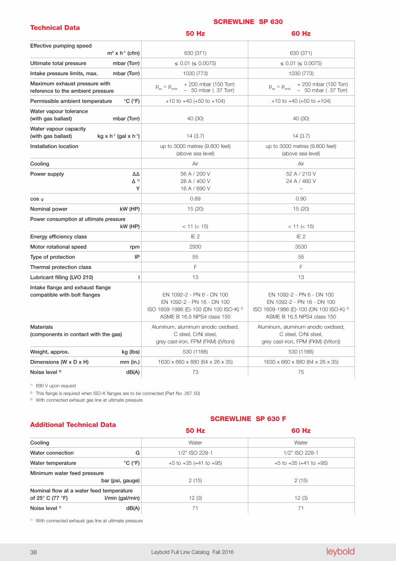
Technical DataSCREWLINE SP 630
50 Hz 60 Hz
Effective pumping speed m3 x h-1 (cfm)
Ultimate total pressure mbar (Torr)
Intake pressure limits, max . mbar (Torr)
Maximum exhaust pressure with reference to the ambient pressure
Permissible ambient temperature °C (°F)
Water vapour tolerance (with gas ballast) mbar (Torr)
Water vapour capacity (with gas ballast) kg x h-1 (gal x h-1)
Installation location
Cooling
Power supply ∆∆ ∆ 1)
Y
cos
Nominal power kW (HP)
Power consumption at ultimate pressure kW (HP)
Energy efficiency class
Motor rotational speed rpm
Type of protection IP
Thermal protection class
Lubricant filling (LVO 210) l
Intake flange and exhaust flange compatible with bolt flanges
Materials (components in contact with the gas)
Weight, approx . kg (lbs)
Dimensions (W x D x H) mm (in .)
Noise level 3) dB(A)
1) 690 V upon request2) This flange is required when ISO-K flanges are to be connected (Part No . 267 50)3) With connected exhaust gas line at ultimate pressure
630 (371) 630 (371)
≤ 0.01(≤ 0.0075) ≤ 0.01(≤ 0 .0075)
1030 (773) 1030 (773) + 200 mbar (150 Torr) + 200 mbar (150 Torr) pex = pamb pex = pamb – 050 mbar (037 Torr) – 050 mbar (037 Torr)
+10 to +40 (+50 to +104) +10 to +40 (+50 to +104)
40 (30) 40 (30)
14 (3 .7) 14 (3 .7)
up to 3000 metres (9 .800 feet) up to 3000 metres (9 .800 feet) (above sea level) (above sea level)
Air Air
56 A / 200 V 52 A / 210 V 28 A / 400 V 24 A / 460 V 16 A / 690 V –
0 .89 0 .90
15 (20) 15 (20)
< 11 (< 15) < 11 (< 15)
IE 2 IE 2
2930 3530
55 55
F F
13 13
EN 1092-2 - PN 6 - DN 100 EN 1092-2 - PN 6 - DN 100 EN 1092-2 - PN 16 - DN 100 EN 1092-2 - PN 16 - DN 100 ISO 1609-1986 (E)-100 (DN 100 ISO-K) 2) ISO 1609-1986 (E)-100 (DN 100 ISO-K) 2) ASME B 16 .5 NPS4 class 150 ASME B 16 .5 NPS4 class 150
Aluminum, aluminum anodic oxidised, Aluminum, aluminum anodic oxidised, C steel, CrNi steel, C steel, CrNi steel, grey cast-iron, FPM (FKM) ((Viton)) grey cast-iron, FPM (FKM) ((Viton))
530 (1166) 530 (1166)
1630 x 660 x 880 (64 x 26 x 35) 1630 x 660 x 880 (64 x 26 x 35)
73 75
Additional Technical DataSCREWLINE SP 630 F
50 Hz 60 Hz
Cooling
Water connection G
Water temperature °C (°F)
Minimum water feed pressure bar (psi, gauge)
Nominal flow at a water feed temperature of 25° C (77 °F) l/min (gal/min)
Noise level 1) dB(A)
1) With connected exhaust gas line at ultimate pressure
Water Water
1/2" ISO 228-1 1/2" ISO 228-1
+5 to +35 (+41 to +95) +5 to +35 (+41 to +95)
2 (15) 2 (15)
12 (3) 12 (3)
71 71

Dry
Com
pres
sing
Vacu
um P
umps
leybold Leybold Full Line Catalog Fall 2016 39
Ordering Information
Screw Vacuum Pump SP 630 air cooled, with manual gas ballast
Screw Vacuum Pump SP 630 F water cooled, with adapter for RUVAC 2001 and electromagnetic gas ballast
with manual gas ballast
with purge gas kit and manual gas ballast
Screw Vacuum Pump SP 630 S1 water cooled, with castors, purge gas kit and electromagnetic gas ballast
All pumps are equipped as standard with an SP-GUARD
SCREWLINE SP 630 Standard / SP 630 F Standard
50 Hz 60 Hz
Part No . Part No .
117 007 117 008
117 105 117 106
117 107 117 108
117 113 117 114
117 117 117 118
Ordering Information
Screw Vacuum Pump SP 630 with purge gas kit manual gas ballast and air cooled, Category 3G IIC (160 °C (320 °F)) inside
with purge gas kit 24 V gas ballast and water cooled, Category 3G IIC (160 °C (320 °F)) inside
Screw Vacuum Pump SP 630 F water cooled Category 2G3D IIC (160 °C (320 °F)) Category 3G IIC T3 (160 °C (320 °F)) with purge gas monitor, adapter for RUVAC 2001 and electromagnetic gas ballast
All pumps are equipped as standard with an SP-GUARD
For all enquiries and orders relating to category 1 and 2 ATEX products please exclusively use our ATEX questionnaire . You can find this questionnaire at the end of the full-line catalog together with the fax forms or on the Internet under “www .leybold .com” under Download Documents in the area Documentation .
SCREWLINE SP 630 ATEX / SP 630 F ATEX
50 Hz 60 Hz
Part No . Part No .
117 017 117 018
117 115 117 116
117 111 117 112
Ordering Information
Screw Vacuum Pump SP 630 with purge gas monitor and electromagnetic gas ballast
All pumps are equipped as standard with an SP-GUARD
SP 630 O2
50 Hz 60 Hz
Part No . Part No .
117 039 117 040

leyboldLeybold Full Line Catalog Fall 201640
Ordering Information
Accessories
Exhaust silencer
Serviceable silencer
Roots pump adapter
for RUVAC 1001 1)
for RUVAC 2001
for RUVAC WH(U) 2500
for RUVAC WH 4400
Dust filter 2)
Elbow 90° (DN 100 ISO-K)
Clamping screws for DN 63-250 ISO-K
Centering ring for DN 100 ISO-K
Purge vent Kit
Inlet filter adapter DN 100 ISO-K
Solenoid gas ballast kit, 24 V
from serial number 31000530865
Non-return valve (DN 100 PN 6)
Purge gas retrofit kit 3)
Maintenance kit, level 1 (oil change kit)
up to serial number 31000197911
from serial number 31000197911
Maintenance kit, level 2 (rotor inspection kit)
Purge gas connection servicing kit
Filter for gas ballast
Filter for purge gas valve unit
Water filter maintenance kit for SP 630 F
Silencer service kit
Seal kit for SP 630 check valve
1) Must mount to adapter Part No . 119 0212) For information on the dust filter please refer to the Catalog Part “Oil sealed Vacuum Pumps”, Section “SOGEVAC”, Chapter “Accessories”3) Not for ATEX pumps
SCREWLINE SP 630 Standard / SP 630 F Standard
50 Hz / 60 HzPart No .
119 001
119 004V
500 003 173
119 021
155222V
119 024V
951 72
887 26
267 01
268 06
119 060V
119 020
119 054V
119 010
119 030
EK 110 000 792
EK 110 000 832
EK 110 000 793
EK 110 000 827
E 110 000 980
E 110 000 850
EK 110 000 813
EK 500 003 475
EK 110 000 815
Dry
Com
pres
sing
Vacu
um P
umps
Notes
leybold Leybold Full Line Catalog Fall 2016 41
leyboldLeybold Full Line Catalog Fall 201642
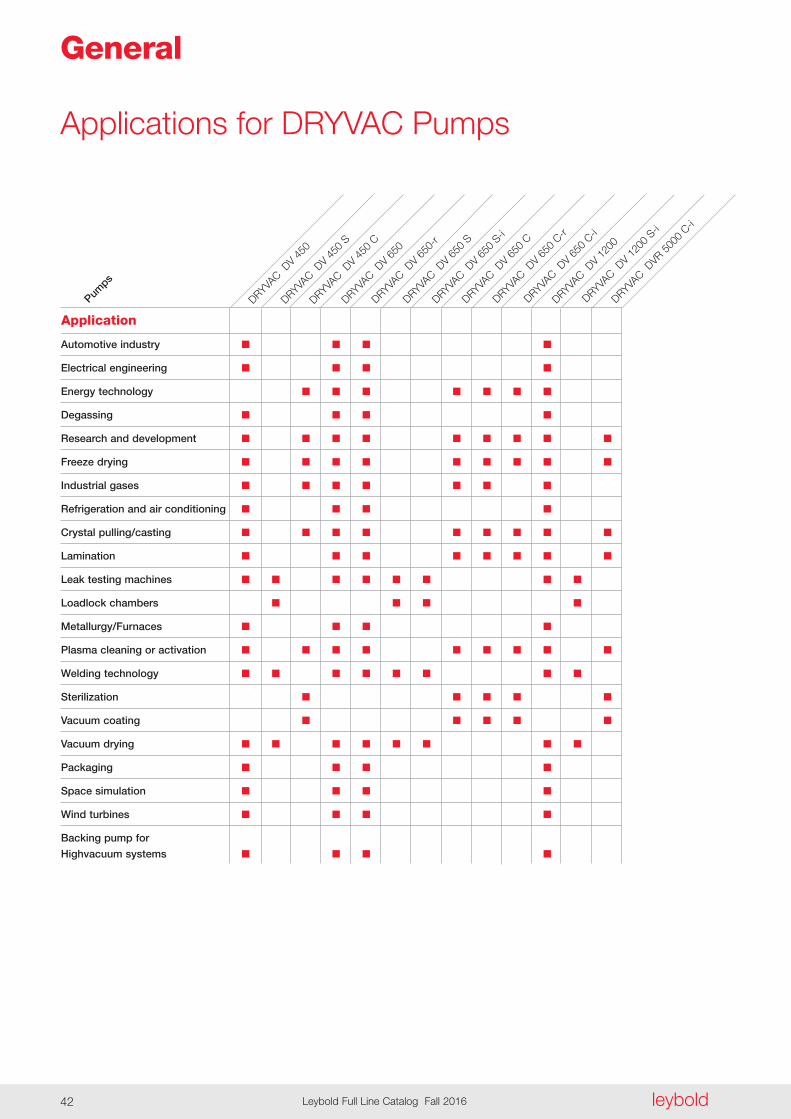
Applications for DRYVAC Pumps
General
Automotive industry n n n n
Electrical engineering n n n n
Energy technology n n n n n n n
Degassing n n n n
Research and development n n n n n n n n n
Freeze drying n n n n n n n n n
Industrial gases n n n n n n n
Refrigeration and air conditioning n n n n
Crystal pulling/casting n n n n n n n n n
Lamination n n n n n n n n
Leak testing machines n n n n n n n n
Loadlock chambers n n n n
Metallurgy/Furnaces n n n n
Plasma cleaning or activation n n n n n n n n n
Welding technology n n n n n n n n
Sterilization n n n n n
Vacuum coating n n n n n
Vacuum drying n n n n n n n n
Packaging n n n n
Space simulation n n n n
Wind turbines n n n n
Backing pump for
Highvacuum systems n n n n
Pumps
DRYVAC D
V 450
S
DRYVAC D
V 650
S
DRYVAC D
V 650
S-i
DRYVAC D
V 650
C
DRYVAC D
V 650
C-r
DRYVAC D
V 120
0
Application
DRYVAC D
V 650
C-i
DRYVAC D
V 650
-r
DRYVAC D
V 120
0 S-i
DRYVAC D
VR 500
0 C-i
DRYVAC D
V 650
DRYVAC D
V 450
C
DRYVAC D
V 450

Dry
Com
pres
sing
Vacu
um P
umps
leybold Leybold Full Line Catalog Fall 2016 43
Oil for DRYVAC pumpsfor different fields of application
LVO 210
LVO 410
n = Standard
l = Possible
The table only lists general applications . Your specific requirements might be subject to deeper analysis . For further questions, please contact our technical Sales support .
Indus
trial g
ases
Crytal
pullin
g/ca
sting
Lamina
tion
Leak
testi
ng m
achin
es
Load
lock c
hambe
rs
Plasma c
leanin
g or
activ
ation
Weld
ing te
chno
logy
Sterila
zition
Space
simula
tion
Wind
turb
ines
Backin
g pu
mp for
Highva
cuum
syste
ms
n n n n n n n n l l n n n n n n n n
l l l n n l n n l l n n
Vacu
um co
ating
Vacu
um d
rying
Packa
ging
Freez
e dryi
ng
Metallu
rgy/F
urna
ces
Refrige
ration
and
air co
nditio
ning
Resea
rch an
d de
velop
ment
Degas
sing
Applicat
ions
Energ
y tec
hnolo
gy
Electric
al en
ginee
ring
LEYBONOL Oils
For information on oil specifications please refer to Catalog Part “Oils / Greases / Lubricants LEYBONOL®” .
Automot
ive in
dustr
y

leyboldLeybold Full Line Catalog Fall 201644
LVO 210
LVO 410
n = Standard
The table only lists general applications . Your specific requirements might be subject to deeper analysis . For further questions, please contact our technical Sales support .
Pumps
DRYVAC D
V 120
0
DRYVAC D
V 650
C-r
DRYVAC D
V 650
C
DRYVAC D
V 650
S-i
DRYVAC D
V 650
S
DRYVAC D
V 650
-r
DRYVAC D
V 650
DRYVAC D
V 650
C-i
For information on oil specifications please refer to Catalog Part “Oils / Greases / Lubricants LEYBONOL®” .
n n n n
n n n n n n n n n
DRYVAC D
V 120
0 S-i
DRYVAC D
VR 500
0 C-i
LEYBONOL OilsDRYVA
C DV 4
50 C
DRYVAC D
V 450
S
DRYVAC D
V 450
Oil for DRYVAC pumpsfor different pump types

Dry
Com
pres
sing
Vacu
um P
umps
leybold Leybold Full Line Catalog Fall 2016 45
DRYVACDV 450 to DVR 5000 C-i
The Benefits of the Screw Principle
The direct pumping path without multi-ple deflections of the gas makes the DRYVAC vacuum pumps very in sen si-tive to foreign materials . This ensures a high reliability in industrial processes . The straight and short path for the gas from the inlet of the pump to its ex haust reduces the dwell time of the gas and thereby reduces potential de posits within the pump . Through the use of a purge gas (e .g . gas ballast), any deposits, particles and conden-sates can be effectively removed .
DRYVAC series
DRYVAC is a new family of dry com-pressing screw vacuum pumps avail-able with different features depending on the specific application . The DRY-VAC family was developed in consider-ation of the special requirements of the photovoltaic, display and process industries . All DRYVAC variants are water cooled, very compact and easy to combine into systems, in particular with the well-proven Roots pumps of the RUVAC WH, WS and WA series .
Just like the Screw Vacuum Pump SP, the DRYVAC was developed for de mand ing applications . However, the range of applications is extended by the DRYVAC to include numerous photovoltaic and display production processes . A unique characteristic of the Screw Vacuum Pump series SCREWLINE is the availability of air cooling and the low internal surface temperatures allowing applications like lamination, for example, to be run with long uptimes and low maintenance complexity .
General
Certifications
leyboldLeybold Full Line Catalog Fall 201646
The Best DRYVAC for every Application
The DRYVAC standard version and the DRYVAC DV S deliver an optimized pumping speed also pressures ex ceeding 100 mbar . DV and DV S types are suited for short cycle opera-tion (load locks, for example) or for the evacua tion of large vacuum chambers .
The DRYVAC pumps are equipped with all features necessary for process industry applications (gas ballast, for example) .
The DRYVAC DV C models offer reli-ability in connection with harsh pro-cesses . They have been optimized for pumping media typically employed in photovoltaic and flat screen production processes . The DRYVAC DV C offers a high pumping speed for hydrogen and owing to its integrated purge gas system is insensitive to dust .
Main features and customer benefits offered by the DRYVAC are the com-pact design, the low-profile and the option of being able to easily build hori-zontally arranged pump systems and the power consumption reduced by up to 30% compared to screw pumps of the 630 m3/h pumping speed class .
These DRYVAC variants are available in different configuration levels: In the case of the DRYVAC-r the frequency converter has been designed for inte-gration within an external electrical cabinet whereas in the case of the other variants the frequency converter has been integrated within the pump . The DRYVAC-i versions expand the DRYVAC by a PLC with a touch screen display and a software user interface allowing easy operation and configuration . The S-i versions are linked to the system as standard through a Profibus or a 24 V I/O inter-face (other interfaces upon request) . Addi tionally, the S-i versions are accom modated in a full enclosure with castors, height adjustable feet and Harting socket . The DRYVAC DV 450 and DV 650 pumps are equipped with one screw pumping stage, the DRYVAC 1200 is equipped with two pump stages run-ning in parallel .
The DRYVAC DVR 5000 C-i is a spe-cial variant of the DRYVAC-i . This process pump is an autonomously controlled combination consisting of a DRYVAC DV 650 C screw pump and a new member of the RUVAC WH series, the WH 2500 . Just like the screw pump, the RUVAC is also operated and controlled by a frequency convert-er (100 Hz max .) The effective pumping speed of the combination amounts to approximately 3800 m3/h for nitrogen .
Design Features of the DRYVAC Family
- Water cooled
- Hermetically sealed screw and Roots pumps, static seals only towards the outside
- Simple mechanical and electrical integration
- Integrated protection function via temperature, exhaust pressure and current consumption
- Small footprint
- Low energy consumption due to optimized rotor geometry and inno-vative motor design meeting IE2 efficiency class requirements
- Wide voltage and frequency range: 380-460 V, 50/60 Hz
- NRTL certified
Dry
Com
pres
sing
Vacu
um P
umps
leybold Leybold Full Line Catalog Fall 2016 47
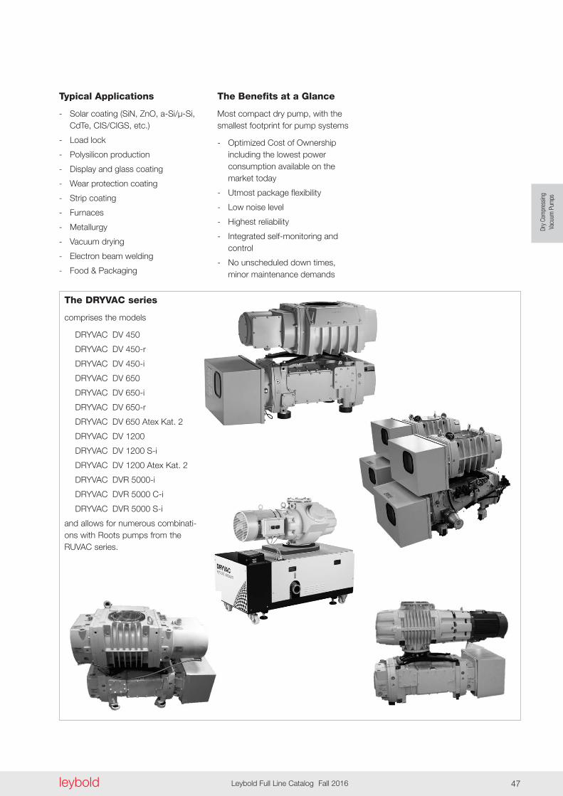
Typical Applications
- Solar coating (SiN, ZnO, a-Si/µ-Si, CdTe, CIS/CIGS, etc .)
- Load lock
- Polysilicon production
- Display and glass coating
- Wear protection coating
- Strip coating
- Furnaces
- Metallurgy
- Vacuum drying
- Electron beam welding
- Food & Packaging
The Benefits at a Glance
Most compact dry pump, with the smallest footprint for pump systems
- Optimized Cost of Ownership including the lowest power consumption available on the market today
- Utmost package flexibility
- Low noise level
- Highest reliability
- Integrated self-monitoring and control
- No unscheduled down times, minor maintenance demands
The DRYVAC series
comprises the models
DRYVAC DV 450
DRYVAC DV 450-r
DRYVAC DV 450-i
DRYVAC DV 650
DRYVAC DV 650-i
DRYVAC DV 650-r
DRYVAC DV 650 Atex Kat . 2
DRYVAC DV 1200
DRYVAC DV 1200 S-i
DRYVAC DV 1200 Atex Kat . 2
DRYVAC DVR 5000-i
DRYVAC DVR 5000 C-i
DRYVAC DVR 5000 S-i
and allows for numerous combinati-ons with Roots pumps from the RUVAC series .

44913
570
417
400
200
236 334
258
3001275
504330
217
7417
7
434
217
217 217
143
279,
5
1)
2)
leyboldLeybold Full Line Catalog Fall 201648
Dimensional drawing for the DRYVAC DV 450 and DV 650
1) with non-return valve 1302) with non-return valve 437

Maßzeichnung
alle Maße in mm
378
74
289
394
279,
517
721
7
262
217
234
217
340
50
44913504
3001213
504258
269330
Maßzeichnung
alle Maße in mm
378
74
289
394
279,
517
721
7
262
217
234
217
340
50
44913504
3001213
504258
269330
Maßzeichnung
alle Maße in mm
378
74
289
394
279,
517
721
7
262
217
234
217
340
50
44913504
3001213
504258
269330
Dry
Com
pres
sing
Vacu
um P
umps
leybold Leybold Full Line Catalog Fall 2016 49
Dimensional drawing for the DRYVAC DV 450-r and DV 650-r
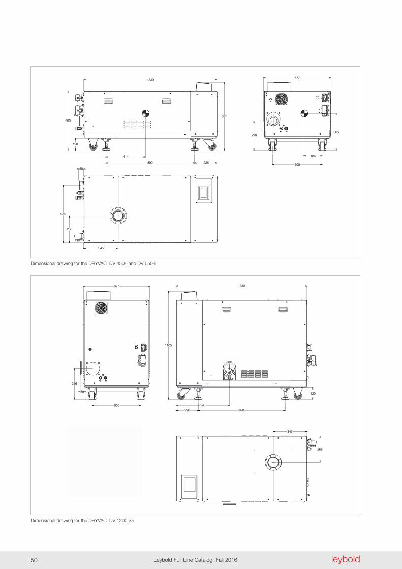
1339
600
120
414
268
345
575
50
890
681
226
296
500
365
184
677
677 1339
1105
316
500
39
545
226 890
345
268
120
leyboldLeybold Full Line Catalog Fall 201650
Dimensional drawing for the DRYVAC DV 450-i and DV 650-i
Dimensional drawing for the DRYVAC DV 1200 S-i
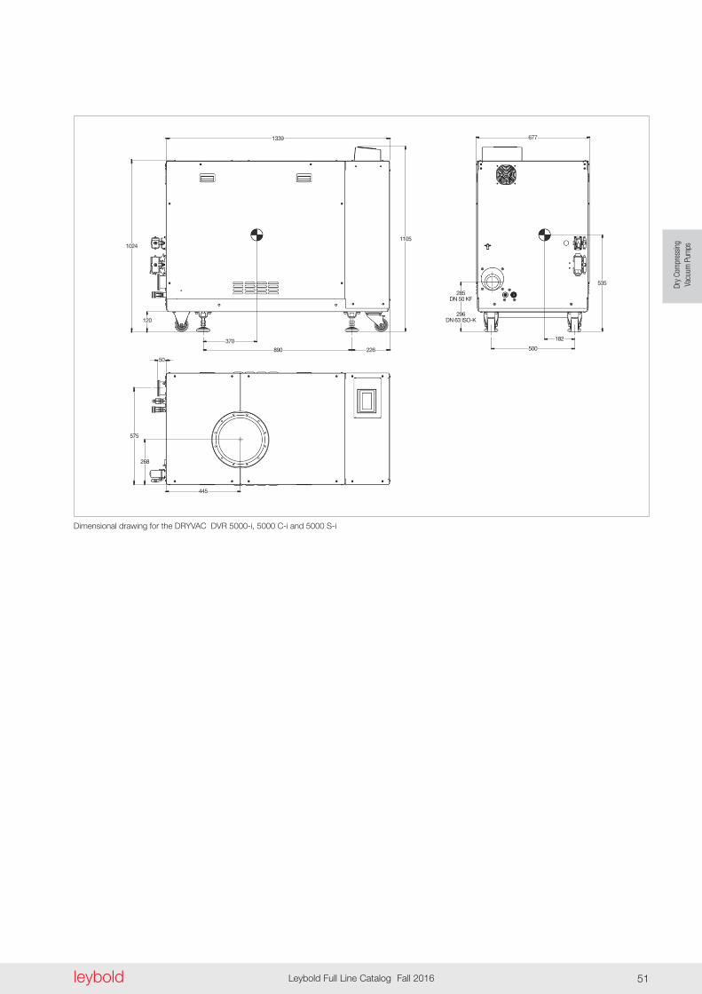
1339
11051024
120
370
890 226
677
535
182
500
285DN 50 KF
296DN 63 ISO-K
50
575
268
445
Dry
Com
pres
sing
Vacu
um P
umps
leybold Leybold Full Line Catalog Fall 2016 51
Dimensional drawing for the DRYVAC DVR 5000-i, 5000 C-i and 5000 S-i
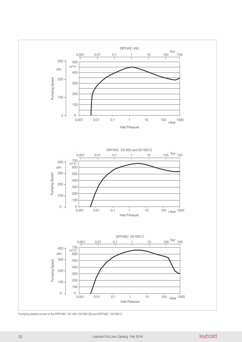
0
100
200
300
400
500
0.001 0.01 0.1 1 10 100 1000
DRYVAC 450
mbarInlet Pressure
Pum
ping
Spe
edTorr
0.1 1 10 100 7500.001 0.01
0
100
200
300
cfmm3·h-1
0
100
200
300
400
500
600
700
0.001 0.01 0.1 1 10 100 1000
DRYVAC DV 650 and DV 650 S
mbarInlet Pressure
Torr0.1 1 10 100 7500.001 0.01
0
100
200
300
400
cfmm3·h-1
Pum
ping
Spe
ed
0
100
200
300
400
500
600
700
0.001 0.01 0.1 1 10 100 1000
DRYVAC DV 650 C
mbarInlet Pressure
Torr0.1 1 10 100 7500.001 0.01
0
100
200
300
400
cfmm3·h-1
Pum
ping
Spe
ed
leyboldLeybold Full Line Catalog Fall 201652
Pumping speed curves of the DRYVAC DV 450, DV 650 (S) and DRYVAC DV 650 C
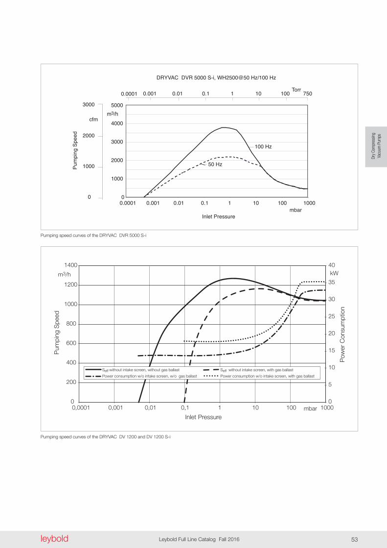
Torr0.1 1 10 100 7500.001 0.010.0001
0
1000
2000
3000
cfm
Inlet Pressure
0
1000
2000
3000
4000
5000
0.0001 0.001 0.01 0.1 1 10 100 1000
Pum
ping
Spe
edDRYVAC DVR 5000 S-i, WH2500@50 Hz/100 Hz
mbar
m3/h
100 Hz
50 Hz
Pum
ping
Spe
ed
Inlet Pressure
Pow
er C
onsu
mpt
ion
Dry
Com
pres
sing
Vacu
um P
umps
leybold Leybold Full Line Catalog Fall 2016 53
Pumping speed curves of the DRYVAC DV 1200 and DV 1200 S-i
Pumping speed curves of the DRYVAC DVR 5000 S-i
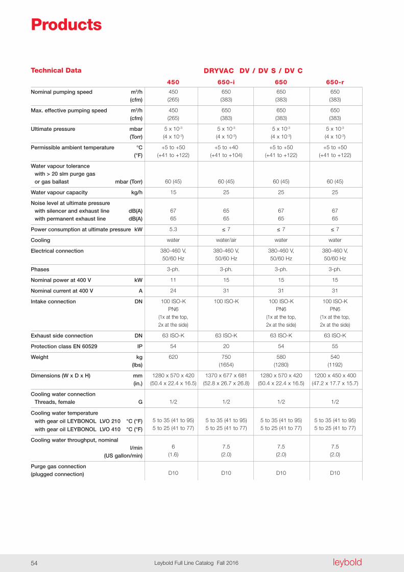
leyboldLeybold Full Line Catalog Fall 201654
Technical Data DRYVAC DV / DV S / DV C
450 650-i 650 650-r
Nominal pumping speed m3/h (cfm)
Max . effective pumping speed m3/h (cfm)
Ultimate pressure mbar (Torr)
Permissible ambient temperature °C (°F)
Water vapour tolerance with > 20 slm purge gas or gas ballast mbar (Torr)
Water vapour capacity kg/h
Noise level at ultimate pressure with silencer and exhaust line dB(A) with permanent exhaust line dB(A)
Power consumption at ultimate pressure kW
Cooling
Electrical connection
Phases
Nominal power at 400 V kW
Nominal current at 400 V A
Intake connection DN
Exhaust side connection DN
Protection class EN 60529 IP
Weight kg (lbs)
Dimensions (W x D x H) mm (in .)
Cooling water connection Threads, female G
Cooling water temperature
with gear oil LEYBONOL LVO 210 °C (°F)
with gear oil LEYBONOL LVO 410 °C (°F)
Cooling water throughput, nominal l/min (US gallon/min)
Purge gas connection (plugged connection)
450 650 650 650 (265) (383) (383) (383)
450 650 650 650 (265) (383) (383) (383)
5 x 10⁻³ 5 x 10⁻³ 5 x 10⁻³ 5 x 10⁻³ (4 x 10⁻³) (4 x 10⁻³) (4 x 10⁻³) (4 x 10⁻³)
+5 to +50 +5 to +40 +5 to +50 +5 to +50 (+41 to +122) (+41 to +104) (+41 to +122) (+41 to +122)
60 (45) 60 (45) 60 (45) 60 (45)
15 25 25 25
67 65 67 67 65 65 65 65
5.3 ≤ 7 ≤ 7 ≤ 7
water water/air water water
380-460 V, 380-460 V, 380-460 V, 380-460 V, 50/60 Hz 50/60 Hz 50/60 Hz 50/60 Hz
3-ph . 3-ph . 3-ph . 3-ph .
11 15 15 15
24 31 31 31
100 ISO-K 100 ISO-K 100 ISO-K 100 ISO-K PN6 PN6 PN6 (1x at the top, (1x at the top, (1x at the top, 2x at the side) 2x at the side) 2x at the side)
63 ISO-K 63 ISO-K 63 ISO-K 63 ISO-K
54 20 54 55
620 750 580 540 (1654) (1280) (1192)
1280 x 570 x 420 1370 x 677 x 681 1280 x 570 x 420 1200 x 450 x 400 (50 .4 x 22 .4 x 16 .5) (52 .8 x 26 .7 x 26 .8) (50 .4 x 22 .4 x 16 .5) (47 .2 x 17 .7 x 15 .7)
1/2 1/2 1/2 1/2
5 to 35 (41 to 95) 5 to 35 (41 to 95) 5 to 35 (41 to 95) 5 to 35 (41 to 95) 5 to 25 (41 to 77) 5 to 25 (41 to 77) 5 to 25 (41 to 77) 5 to 25 (41 to 77)
6 7 .5 7 .5 7 .5 (1 .6) (2 .0) (2 .0) (2 .0)
D10 D10 D10 D10
Products
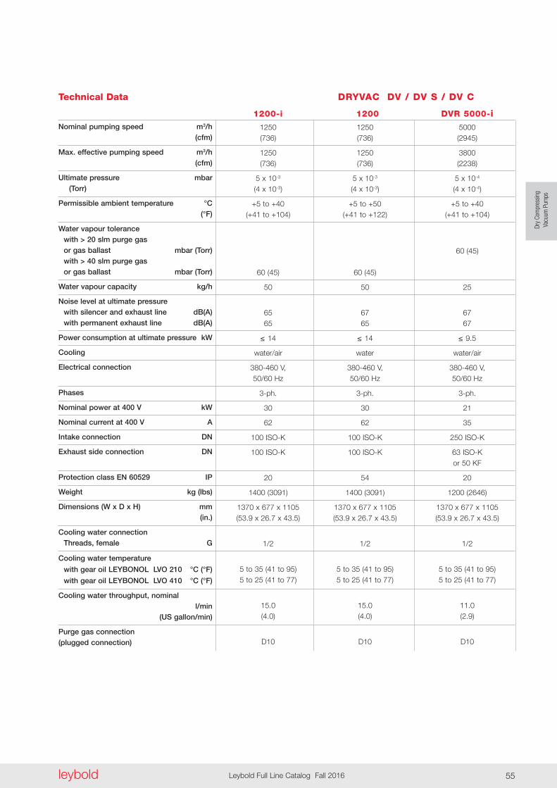
Dry
Com
pres
sing
Vacu
um P
umps
leybold Leybold Full Line Catalog Fall 2016 55
Technical Data DRYVAC DV / DV S / DV C
1200-i 1200 DVR 5000-iNominal pumping speed m3/h (cfm)
Max . effective pumping speed m3/h (cfm)
Ultimate pressure mbar (Torr)
Permissible ambient temperature °C (°F)
Water vapour tolerance with > 20 slm purge gas or gas ballast mbar (Torr) with > 40 slm purge gas or gas ballast mbar (Torr)
Water vapour capacity kg/h
Noise level at ultimate pressure with silencer and exhaust line dB(A) with permanent exhaust line dB(A)
Power consumption at ultimate pressure kW
Cooling
Electrical connection
Phases
Nominal power at 400 V kW
Nominal current at 400 V A
Intake connection DN
Exhaust side connection DN
Protection class EN 60529 IP
Weight kg (lbs)
Dimensions (W x D x H) mm (in .)
Cooling water connection Threads, female G
Cooling water temperature
with gear oil LEYBONOL LVO 210 °C (°F)
with gear oil LEYBONOL LVO 410 °C (°F)
Cooling water throughput, nominal l/min (US gallon/min)
Purge gas connection (plugged connection)
1250 1250 5000 (736) (736) (2945)
1250 1250 3800 (736) (736) (2238)
5 x 10⁻³ 5 x 10⁻³ 5 x 10⁻⁴ (4 x 10⁻³) (4 x 10⁻³) (4 x 10⁻⁴)
+5 to +40 +5 to +50 +5 to +40 (+41 to +104) (+41 to +122) (+41 to +104)
60 (45) 60 (45) 60 (45)
50 50 25
65 67 67 65 65 67
≤ 14 ≤ 14 ≤ 9 .5
water/air water water/air
380-460 V, 380-460 V, 380-460 V, 50/60 Hz 50/60 Hz 50/60 Hz
3-ph . 3-ph . 3-ph .
30 30 21
62 62 35
100 ISO-K 100 ISO-K 250 ISO-K
100 ISO-K 100 ISO-K 63 ISO-K or 50 KF
20 54 20
1400 (3091) 1400 (3091) 1200 (2646)
1370 x 677 x 1105 1370 x 677 x 1105 1370 x 677 x 1105 (53 .9 x 26 .7 x 43 .5) (53 .9 x 26 .7 x 43 .5) (53 .9 x 26 .7 x 43 .5)
1/2 1/2 1/2
5 to 35 (41 to 95) 5 to 35 (41 to 95) 5 to 35 (41 to 95) 5 to 25 (41 to 77) 5 to 25 (41 to 77) 5 to 25 (41 to 77)
15 .0 15 .0 11 .0 (4 .0) (4 .0) (2 .9)
D10 D10 D10
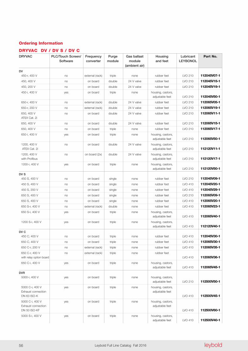
leyboldLeybold Full Line Catalog Fall 201656
Ordering Information
DRYVAC DV / DV S / DV CDRYVAC PLC/Touch Screen/ Frequency Purge Gas ballast Housing Lubricant Part No . Software converter module module and feet LEYBONOL (ambient air)
DV 450-r, 400 V no external (rack) triple none rubber feet LVO 210 112045V07-1
450, 400 V no on board double 24 V valve rubber feet LVO 210 112045V15-1
450, 200 V no on board double 24 V valve rubber feet LVO 210 112045V19-1
450-i, 400 V yes on board triple none housing, castors,
adjustable feet LVO 210 112045V50-1
650-r, 400 V no external (rack) double 24 V valve rubber feet LVO 210 112065V05-1
650-r, 200 V no external (rack) double 24 V valve rubber feet LVO 210 112065V19-1
650, 400 V no on board double 24 V valve rubber feet LVO 210 112065V11-1
ATEX Cat . 2i
650, 400 V no on board double 24 V valve rubber feet LVO 210 112065V15-1
650, 400 V no on board triple none rubber feet LVO 210 112065V17-1
650-i, 400 V yes on board triple none housing, castors,
adjustable feet LVO 210 112065V50-1
1200, 400 V no on board double 24 V valve housing, castors,
ATEX Cat . 2i adjustable feet LVO 210 112120V11-1
1200, 400 V no on board (2x) double 24 V valve housing, castors,
with Profibus adjustable feet LVO 210 112120V17-1
1200-i, 400 V yes on board triple none housing, castors,
adjustable feet LVO 210 112120V50-1
DV S 450 S, 400 V no on board single none rubber feet LVO 210 112045V09-1
450 S, 400 V no on board single none rubber feet LVO 410 112045V20-1
450 S, 200 V no on board single none rubber feet LVO 410 112045V29-1
650 S, 400 V no on board single none rubber feet LVO 210 112065V09-1
650 S, 400 V no on board single none rubber feet LVO 410 112065V20-1
650 S-r, 400 V no external (rack) double none rubber feet LVO 410 112065V23-1
650 S-i, 400 V yes on board triple none housing, castors,
adjustable feet LVO 410 112065V40-1
1200 S-i, 400 V yes on board triple none housing, castors,
adjustable feet LVO 410 112120V40-1
DV C 450 C, 400 V no on board triple none rubber feet LVO 410 112045V30-1
650 C, 400 V no on board triple none rubber feet LVO 410 112065V30-1
650 C-r, 200 V no external (rack) triple none rubber feet LVO 410 112065V35-1
650 C-r, 400 V no external (rack) triple none rubber feet
with relay option board LVO 410 112065V36-1
650 C-i, 400 V yes on board triple none housing, castors,
adjustable feet LVO 410 112065V45-1
DVR 5000-i, 400 V yes on board triple none housing, castors,
adjustable feet LVO 210 112500V50-1
5000 C-i, 400 V yes on board triple none housing, castors,
Exhaust connection adjustable feet
DN 63 ISO-K LVO 410 112500V45-1
5000 C-i, 400 V yes on board triple none housing, castors,
Exhaust connection adjustable feet
DN 50 ISO-KF LVO 410 112500V60-1
5000 S-i, 400 V yes on board triple none housing, castors,
adjustable feet LVO 410 112500V40-1
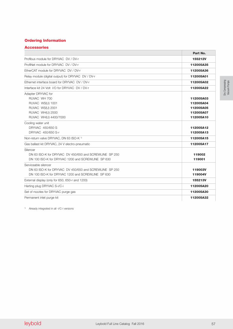
Dry
Com
pres
sing
Vacu
um P
umps
leybold Leybold Full Line Catalog Fall 2016 57
Part No .
Profibus module for DRYVAC DV / DV-r 155212V
ProfiNet module for DRYVAC DV / DV-r 112005A35
EtherCAT module for DRYVAC DV / DV-r 112005A36
Relay module (digital output) for DRYVAC DV / DV-r 112005A01
Ethernet interface board for DRYVAC DV / DV-r 112005A02
Interface kit 24 Volt I/O for DRYVAC DV / DV-r 112005A22
Adapter DRYVAC for
RUVAC WH 700 112005A03
RUVAC WS(U) 1001 112005A04
RUVAC WS(U) 2001 112005A05
RUVAC WH(U) 2500 112005A07
RUVAC WH(U) 4400/7000 112005A10
Cooling water unit
DRYVAC 450/650 S 112005A12
DRYVAC 450/650 S-r 112005A13
Non-return valve DRYVAC, DN 63 ISO-K 1) 112005A15
Gas ballast kit DRYVAC, 24 V electro-pneumatic 112005A17
Silencer
DN 63 ISO-K for DRYVAC DV 450/650 and SCREWLINE SP 250 119002
DN 100 ISO-K for DRYVAC 1200 and SCREWLINE SP 630 119001
Serviceable silencer
DN 63 ISO-K for DRYVAC DV 450/650 and SCREWLINE SP 250 119003V
DN 100 ISO-K for DRYVAC 1200 and SCREWLINE SP 630 119004V
External display (only for 650, 650-r and 1200) 155213V
Harting plug DRYVAC S-i/C-i 112005A20
Set of nozzles for DRYVAC purge gas 112005A30
Permanent inlet purge kit 112005A32
1) Already integrated in all -i/C-i versions
Ordering Information
Accessories

leyboldLeybold Full Line Catalog Fall 201658
Only available for purchase in North and South America
Applications for CHEMROVAC Pumps
n n n n n
n n n n n
n n n n n
n n n n n
Pharmaceuticals
Fine chemicals
Flavours and fragances
Fatty acids
Pumps
TRV 4
04
TRV 4
05
TRV 4
06
Typical Application
TRV 4
10
TRV 4
08
General
The CHEMROVAC TRV pumps are not designed to the European ATEX direc-tive (94/9/EC) . They can therefore not be installed in Europe into flame proof
environments or be used to pump flammable materials . This has always to be considered if you want to export these pumps into
Operating Principle
The CHEMROVAC TRV pumps are 4-stage roots pumps . Each stage con-sists of two rotors rotating in opposite directions inside a casing (pumping chamber) and having slight clearances against the inside wall surface of the casing and also between the rotors . In the sequence from (1) to (4) in the fig-ures on this and the following page each phase of rotor rotation is shown . The light area in the figure shows inlet pressure regions of a stage whereas the slash area shows discharge pres-sure regions . The pumping principle of this pump is explained below, using a
flow of A-B-C-S-A, and in the part of A-B-C the internal compression heat is continuously dissipat ed . By this a high-efficiency and a high pressure ratio are obtained .
cold wall type back flow mechanism, referring to left rotor in each figure .
As described above, compression takes place using the properly cooled gas of the same pressure as the dis-charge pressure, and therefore, the temperature rise inside the case is kept low . That means, gas discharged out of the discharge port A is cooled by the cold wall B, and a portion of this cooled gas is injected as a back flow cooling medium via the port C into the moving volume S for back flow compression . Therefore, the gas has a circulating
Fig . 1This figure shows a condition just before the rotor catches the gas of the inlet pressure region into the moving volume S .
Europe or install it in accordance to European directives and legal require-ments .
General

Dry
Com
pres
sing
Vacu
um P
umps
leybold Leybold Full Line Catalog Fall 2016 59
Advantages to the User
- Oil-free compression
- Reliable separation between swept volume and gear box side (avoiding of oil back streaming)
- Motor not on gear box side, no oil leaking by motor shaft
- Safe separation of motor and gear box area by additional shaft seal purge
- Materials of construction suitable for most chemicals to be pumped
- Flat speed curve from atmosphere to 10 mbar (7 .5 Torr)
- Good liquid handling because of vertical orientation
- Easy access of swept volume for cleaning
- Easy to equip with local certified flame proof motor
- Nearly no electrical control for standard operation needed
Typical Applications
- Distillation
- Drying
- Freeze drying
- Degassing
- Central house vacuum
- Crystallisation
- Evaporation
Accessories
As standard accessory an exhaust silencer is available for each pump .
The pumps can be combined with mechanical roots blowers to increase pumping speed and to achieve lower ultimate pressure .
CHEMROVAC TRV pumps can also be the basic part of a bespoken system that complies to special process re quire ments to customer’s needs .
Supplied Equipment
The basic pump CHEMROVAC TRV is a pump without a motor . A suitable motor complying with the local regula-tions will normally be mounted by Leybold . In this case the CHEMROVAC TRV is supplied ready for installation and connection .
In some cases the motor will be deliv-ered and mounted by the end-user . In this case the user is responsible for correct selection and safe mounting of the motor . LV will not take over any responsibility for the motor and motor mounting in such a case .
The electrical connections to the pump must be provided by suitably trained staff of the customer .
The basic CHEMROVAC TRV pump is delivered with:
- Nitrogen shaft seal purge unit
- The required amount of gear oil (is supplied separately)
- 2 crane eyes for transporting the pump
- Operating Instructions
Fig . 2In this figure, the rotor has completely caught the gas of the inlet pressure region into the moving volume S . Gas which is already discharged out at exit port A is properly cooled by the cold outside wall of the gas path B . One part of this gas flows back through the port C into the moving volume S . The other part of the cooled exhausted gas is flowing into the next stage of the pump .
Fig . 3As the rotor rotates further, the gas which has been cooled properly by the cold wall B flows suffi-ciently into the S cavity; the pressure in the chamber S is approaching the discharge pressure .
Fig . 4In this condition the pressure in the moving vol ume portion S is approximately equal to the dis charge pressure, and the discharge port A and the cavity S are just before opening to each other .
Moreover, because the casing enclos-ing the rotors is not cooled directly, the clearances between the rotor and the casing is not reduced due to heat con-traction, reducing the possibility of contact between both .
In some cases condensable gas can condense in the different stages ac cord ing to its vapor pressure . Condensate either condensed in the pump or as liquid carry over from the
process will flow down with the gas stream and discharged to atmosphere in an exhaust drain tank .
The exhaust drain tank is mounted at the exhaust of the last pump stage . It is located either below the exhaust cooler (large pumps) or pump outlet flange (small pumps) . It collects liquid con-densed from the pump or the exhaust cooler .
The larger pumps are equipped with a water cooled exhaust cooler as stand-ard . The cooler is designed as shell and tube cooler . This reduces the ex haust gas temperature to an accept-able limit . Also vapors from the ex haust gas stream are partially con densed . Condensed liquid is drained into the exhaust drain tank below the condens er .

0
50
100
150
200
250
300
350
400
450
500
0.1 1 10 100 1000
TRV 404
TRV 405
TRV 406
TRV 408
TRV 410
m3/h
Pressure
10-1 1 10 100 750Torr
300
200
100
1
50
cfm
Pum
ping
Spe
ed
mbar
0
100
200
300
400
500
600
0.1 1 10 100 1000
TRV 410
TRV 408
TRV 406
TRV 405
TRV 404
10-1 1 10 100 750Torr
300
200
100
1
50
cfm
m3/h
Pressure
Pum
ping
Spe
ed
mbar
0
50
100
150
200
250
300
350
400
450
500
0.1 1 10 100 1000
TRV 404
TRV 405
TRV 406
TRV 408
TRV 410
m3/h
Pressure
10-1 1 10 100 750Torr
300
200
100
1
50
cfm
Pum
ping
Spe
ed
mbar
0
100
200
300
400
500
600
0.1 1 10 100 1000
TRV 410
TRV 408
TRV 406
TRV 405
TRV 404
10-1 1 10 100 750Torr
300
200
100
1
50
cfm
m3/h
Pressure
Pum
ping
Spe
ed
mbar
leyboldLeybold Full Line Catalog Fall 201660
CHEMROVAC TRV 404 to 410
CHEMROVAC TRV 404 (left) and TRV 410 (right)
Pumping speed curves for the CHEMROVAC TRV at 50 Hz
Products
Pumping speed curves for the CHEMROVAC TRV at 60 Hz
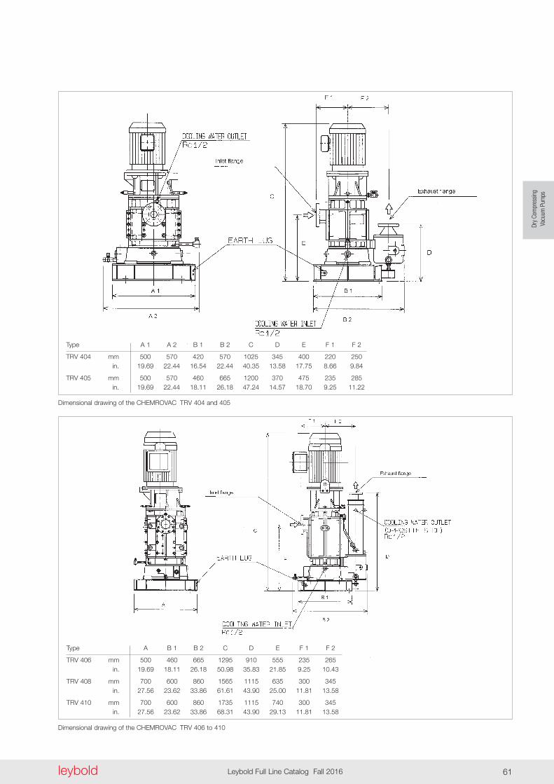
Dry
Com
pres
sing
Vacu
um P
umps
leybold Leybold Full Line Catalog Fall 2016 61
Dimensional drawing of the CHEMROVAC TRV 404 and 405
Dimensional drawing of the CHEMROVAC TRV 406 to 410
Type A B 1 B 2 C D E F 1 F 2
TRV 406 mm 500 460 665 1295 910 555 235 265 in . 19 .69 18 .11 26 .18 50 .98 35 .83 21 .85 9 .25 10 .43
TRV 408 mm 700 600 860 1565 1115 635 300 345 in . 27 .56 23 .62 33 .86 61 .61 43 .90 25 .00 11 .81 13 .58
TRV 410 mm 700 600 860 1735 1115 740 300 345 in . 27 .56 23 .62 33 .86 68 .31 43 .90 29 .13 11 .81 13 .58
Type A 1 A 2 B 1 B 2 C D E F 1 F 2
TRV 404 mm 500 570 420 570 1025 345 400 220 250 in . 19 .69 22 .44 16 .54 22 .44 40 .35 13 .58 17 .75 8 .66 9 .84
TRV 405 mm 500 570 460 665 1200 370 475 235 285 in . 19 .69 22 .44 18 .11 26 .18 47 .24 14 .57 18 .70 9 .25 11 .22
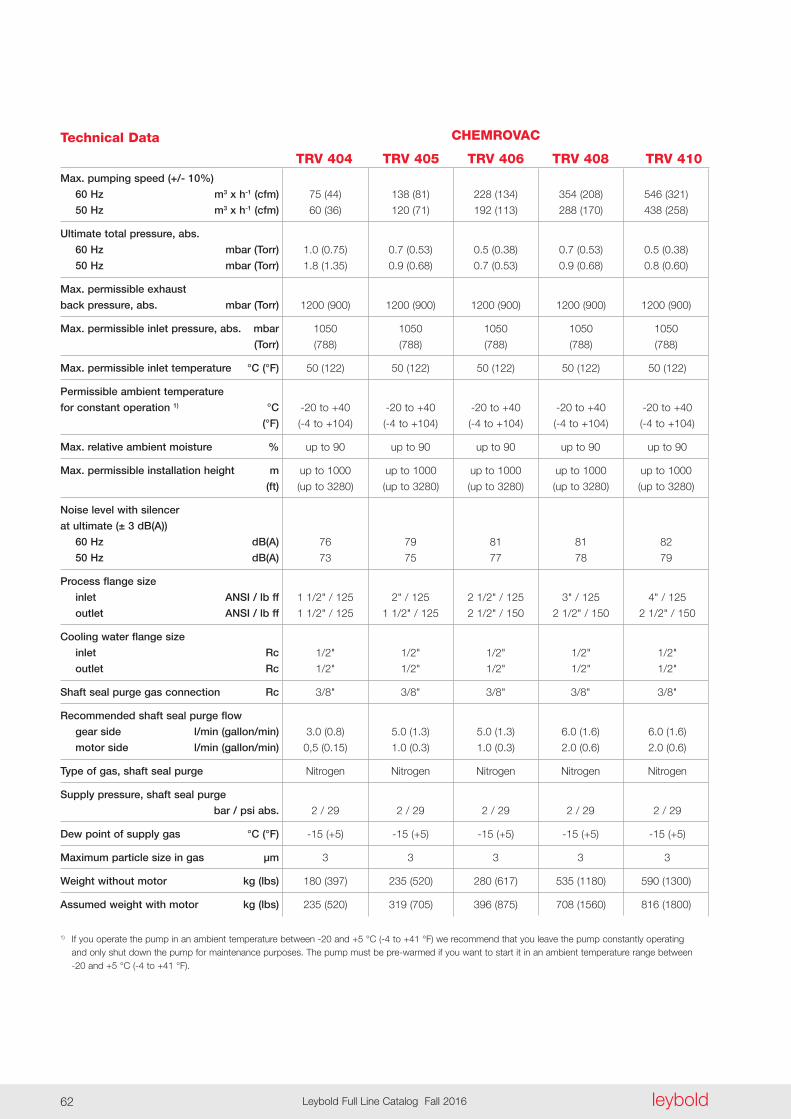
leyboldLeybold Full Line Catalog Fall 201662
Technical Data
Max . pumping speed (+/- 10%)
60 Hz m3 x h-1 (cfm)
50 Hz m3 x h-1 (cfm)
Ultimate total pressure, abs .
60 Hz mbar (Torr)
50 Hz mbar (Torr)
Max . permissible exhaust
back pressure, abs . mbar (Torr)
Max . permissible inlet pressure, abs . mbar
(Torr)
Max . permissible inlet temperature °C (°F)
Permissible ambient temperature
for constant operation 1) °C
(°F)
Max . relative ambient moisture %
Max . permissible installation height m
(ft)
Noise level with silencer
at ultimate (± 3 dB(A))
60 Hz dB(A)
50 Hz dB(A)
Process flange size
inlet ANSI / lb ff
outlet ANSI / lb ff
Cooling water flange size
inlet Rc
outlet Rc
Shaft seal purge gas connection Rc
Recommended shaft seal purge flow
gear side l/min (gallon/min)
motor side l/min (gallon/min)
Type of gas, shaft seal purge
Supply pressure, shaft seal purge
bar / psi abs .
Dew point of supply gas °C (°F)
Maximum particle size in gas µm
Weight without motor kg (lbs)
Assumed weight with motor kg (lbs)
1) If you operate the pump in an ambient temperature between -20 and +5 °C (-4 to +41 °F) we recommend that you leave the pump constantly operating and only shut down the pump for maintenance purposes . The pump must be pre-warmed if you want to start it in an ambient temperature range between -20 and +5 °C (-4 to +41 °F) .
75 (44) 138 (81) 228 (134) 354 (208) 546 (321)
60 (36) 120 (71) 192 (113) 288 (170) 438 (258)
1 .0 (0 .75) 0 .7 (0 .53) 0 .5 (0 .38) 0 .7 (0 .53) 0 .5 (0 .38)
1 .8 (1 .35) 0 .9 (0 .68) 0 .7 (0 .53) 0 .9 (0 .68) 0 .8 (0 .60)
1200 (900) 1200 (900) 1200 (900) 1200 (900) 1200 (900)
1050 1050 1050 1050 1050
(788) (788) (788) (788) (788)
50 (122) 50 (122) 50 (122) 50 (122) 50 (122)
-20 to +40 -20 to +40 -20 to +40 -20 to +40 -20 to +40
(-4 to +104) (-4 to +104) (-4 to +104) (-4 to +104) (-4 to +104)
up to 90 up to 90 up to 90 up to 90 up to 90
up to 1000 up to 1000 up to 1000 up to 1000 up to 1000
(up to 3280) (up to 3280) (up to 3280) (up to 3280) (up to 3280)
76 79 81 81 82
73 75 77 78 79
1 1/2" / 125 2" / 125 2 1/2" / 125 3" / 125 4" / 125
1 1/2" / 125 1 1/2" / 125 2 1/2" / 150 2 1/2" / 150 2 1/2" / 150
1/2" 1/2" 1/2" 1/2" 1/2"
1/2" 1/2" 1/2" 1/2" 1/2"
3/8" 3/8" 3/8" 3/8" 3/8"
3 .0 (0 .8) 5 .0 (1 .3) 5 .0 (1 .3) 6 .0 (1 .6) 6 .0 (1 .6)
0,5 (0 .15) 1 .0 (0 .3) 1 .0 (0 .3) 2 .0 (0 .6) 2 .0 (0 .6)
Nitrogen Nitrogen Nitrogen Nitrogen Nitrogen
2 / 29 2 / 29 2 / 29 2 / 29 2 / 29
-15 (+5) -15 (+5) -15 (+5) -15 (+5) -15 (+5)
3 3 3 3 3
180 (397) 235 (520) 280 (617) 535 (1180) 590 (1300)
235 (520) 319 (705) 396 (875) 708 (1560) 816 (1800)
CHEMROVAC
TRV 404 TRV 405 TRV 406 TRV 408 TRV 410

Dry
Com
pres
sing
Vacu
um P
umps
leybold Leybold Full Line Catalog Fall 2016 63
Additional Technical Data
Motor flame proof protection
Start-up method
Voltage V
Installed power 60 Hz kW (HP) 50 Hz kW (HP)
Absorbed power at ultimate pressure 60 Hz kW (HP) 50 Hz kW (HP)
Motor frame size NEMA IEC
No . of phases
No . of poles
Motor frequency Hz
Operating frequency Hz
Nominal revolution 1/min
Cooling
Minimum cooling water consumption (at 25 °C (77 °F) inlet temperature) 60 Hz l/min (gallon/min) 50 Hz l/min (gallon/min)
Cooling water temperature °C (°F) °C (°F)
Cooling water supply pressure, abs . bar (psi)
Lubrication bearing motor side (grease) ml gear side (oil)
Oil type for gear box
Volume gear box oil l (gallon)
to local standards, e .g . class 1, division 1, C&D, or Ex d IIB
direct on line or via frequency converter
depending on local requirements
3 .7 (5 .0) 5 .5 (7 .5) 7 .5 (10 .0) 15 .0 (20 .0) 18 .5 (25 .0) 3 .7 (5 .0) 5 .5 (7 .5) 7 .5 (10 .0) 15 .0 (20 .0) 18 .5 (25 .0)
2 .1 (2 .8) 3 .3 (4 .4) 4 .8 (6 .4) 9 .0 (12 .1) 12 .5 (16 .8) 1 .8 (2 .4) 3 .0 (4 .0) 4 .1 (5 .5) 7 .0 (9 .4) 10 .0 (13 .4)
184TC 213TC 215TC 256TC 284TSC 112 M 132 S 132 S 160 M 160 L
3 3 3 3 3
2 2 2 2 2
50 or 60, depending on local conditions
26 to 60
3000 or 3600, depending on motor frequency
water, direct without temperature control valve
5 .0 (1 .3) 7 .0 (1 .9) 10 .0 (2 .7) 20 .0 (5 .3) 28 .0 (7 .4) 5 .0 (1 .3) 7 .0 (1 .9) 10 .0 (2 .7) 20 .0 (5 .3) 28 .0 (7 .4)
+10 to +35 +10 to +35 +10 to +35 +10 to +35 +10 to +35 (+50 to +95) (+50 to +95) (+50 to +95) (+50 to +95) (+50 to +95)
3 to 7 3 to 7 3 to 7 3 to 7 3 to 7 (44 to 102) (44 to 102) (44 to 102) (44 to 102) (44 to 102)
100 200 200 260 260 depends on oil capacity
LVO 130 LVO 130 LVO 130 LVO 130 LVO 130
1 .0 (0 .3) 1 .0 (0 .3) 1 .0 (0 .3) 4 .0 (1 .1) 4 .0 (1 .1)
CHEMROVAC
TRV 404 TRV 405 TRV 406 TRV 408 TRV 410
Ordering Information
Dry vacuum pump
for chemical and pharmaceutical application
CHEMROVAC TRV (without motor)
CHEMROVAC TRV
(with NEMA motor Class 1,
Div . 1, Group C & D, 406/460 V, 60 Hz)
Accessories
Exhaust silencer, filled with mineral wool
Part No . Part No . Part No . Part No . Part No .
134 101 134 102 134 103 134 104 134 105
134 201 V 134 202 V 134 203 V 134 204 V 134 205 V
134 121 134 121 134 122 134 122 134 122
CHEMROVAC
TRV 404 TRV 405 TRV 406 TRV 408 TRV 410

HeadquarterLeybold GmbHBonner Strasse 498D-50968 CologneT: +49-(0)221-347-0F: +49-(0)[email protected]
GermanyLeybold GmbHSales, Service, Support Center (3SC)Bonner Strasse 498D-50968 CologneT: +49-(0)221-347 1234F: +49-(0)221-347 [email protected]
Leybold GmbHSales Area NorthBranch Office BerlinIndustriestrasse 10bD-12099 BerlinT: +49-(0)30-435 609 0F: +49-(0)30-435 609 [email protected]
Leybold GmbHSales Office SouthBranch Office MunichKarl-Hammerschmidt-Strasse 34D-85609 Aschheim-DornachT: +49-(0)89-357 33 9-10F: +49-(0)89-357 33 [email protected]@leybold.com
Leybold Dresden GmbHService Competence CenterZur Wetterwarte 50, Haus 304D-01109 DresdenService:T: +49-(0)351-88 55 00F: +49-(0)351-88 55 [email protected]
Europe
Belgium
Leybold Nederland B.V.Belgisch bijkantoorLeuvensesteenweg 542-9AB-1930 ZaventemSales:T: +32-2-711 00 83F: +32-2-720 83 [email protected]:T: +32-2-711 00 82F: +32-2-720 83 [email protected]
France
Leybold France S.A.S.Parc du Technopolis, Bâtiment Beta3, Avenue du CanadaF-91940 Les Ulis cedexSales and Service:T: +33-1-69 82 48 00F: +33-1-69 07 57 [email protected]@leybold.com
Leybold France S.A.S.Valence Factory640, Rue A. BergèsB.P. 107F-26501 Bourg-lès-Valence CedexT: +33-4-75 82 33 00F: +33-4-75 82 92 [email protected]
Great Britain
Leybold UK LTD.Unit 9Silverglade Business ParkLeatherhead RoadChessingtonSurrey (London)KT9 2QLSales:T: +44-13-7273 7300F: +44-13-7273 [email protected]:T: +44-13-7273 7320F: +44-13-7273 [email protected]
Italy
Leybold Italia S.r.l.Via Trasimeno 8I-20128 MailandSales:T: +39-02-27 22 31F: +39-02-27 20 96 [email protected]:T: +39-02-27 22 31F: +39-02-27 22 32 [email protected]
Netherlands
Leybold Nederland B.V.Floridadreef 102NL-3565 AM UtrechtSales and Service:T: +31-(30) 242 63 30F: +31-(30) 242 63 [email protected]@leybold.com
Switzerland
Leybold Schweiz AG, PfäffikonChurerstrasse 120CH-8808 PfäffikonWarehouse and shipping address:Riedthofstrasse 214CH-8105 RegensdorfSales:T: +41-44-308 40 50F: +41-44-302 43 [email protected]:T: +41-44-308 40 62F: +41-44-308 40 [email protected]
Spain
Leybold Spain, S.A.C/. Huelva, 7E-08940 Cornellà de Llobregat(Barcelona)Sales:T: +34-93-666 43 11F: +34-93-666 43 [email protected]:T: +34-93-666 46 11F: +34-93-685 43 [email protected]
AmericaUSA
Leybold USA Inc.5700 Mellon RoadUSA-Export, PA 15632T: +1-724-327-5700F: [email protected]:T: +1-724-327-5700F: +1-724-333-1217Service:T: +1-724-327-5700F: +1-724-325-3577
Brazil
Leybold do BrasilRod. Vice-Prefeito Hermenegildo Tonolli,nº. 4413 - 6BDistrito IndustrialJundiaí - SPCEP 13.213-086Sales and Service:T: +55 11 3395 3180F: +55 11 99467 [email protected]@leybold.com
AsiaP. R. China
Leybold (Tianjin)International Trade Co. Ltd.Beichen EconomicDevelopment Area (BEDA),No. 8 Western Shuangchen RoadTianjin 300400ChinaSales and Service:T: +86-22-2697 0808F: +86-22-2697 4061F: +86-22-2697 [email protected]@leybold.com
India
Leybold India Pvt Ltd.No. 82(P), 4th PhaseK.I.A.D.B. PlotBommasandra Industrial AreaBangalore - 560 099IndienSales and Service:T: +91-80-2783 9925F: +91-80-2783 [email protected]@leybold.com
Japan
Leybold Japan Co., Ltd.HeadquartersShin-Yokohama A.K.Bldg., 4th floor3-23-3, Shin-YokohamaKohoku-ku, Yokohama-shiKanawaga 222-0033JapanSales:T: +81-45-471-3330F: [email protected]
Leybold Japan Co., Ltd.Tsukuba Technical Service Center1959, Kami-yokobaTsukuba-shi, Ibaraki-shi 305-0854JapanService:T: +81-29 839 5480F: +81-29 839 [email protected]
Malaysia
Leybold MalaysiaLeybold Singapore Pte Ltd.No. 1 Jalan Hi-Tech 2/6Kulim Hi-Tech ParkKulim, Kedah DarulAman 09000MalaysiaSales and Service:T: +604 4020 222F: +604 4020 [email protected]@leybold.com
South Korea
Leybold Korea Ltd.3F. Jellzone 2 TowerJeongja-dong 159-4Bundang-gu Sungnam-siGyeonggi-doBundang 463-384, KoreaSales:T: +82-31 785 1367F: +82-31 785 [email protected]:623-7, Upsung-DongCheonan-SiChungcheongnam-DoKorea 330-290T: +82-41 589 3035F: +82-41 588 [email protected]
Singapore
Leybold Singapore Pte Ltd.8 Commonwealth Lane #01-01Singapore 149555SingaporeSales and Service:T: +65-6303 7030F: +65-6773 [email protected]@leybold.com
Taiwan
Leybold Taiwan Ltd.No 416-1, Sec. 3Chunghsin Rd., ChutungHsinchu County 310Taiwan, R.O.C.Sales and Service:T: +886-3-500 1688F: +886-3-583 [email protected]@leybold.com
Sales and Service