User Manual Interroll Drum Motors - Rotor Technical Services

INSPIRED BY EFFICIENCY
CATALOGDRUM MOTOR DM 0080

"Inspired by Efficiency"
Smart handling of resources is mandatory for Interroll. Because we are convinced that efficiency is
a fundamental value. It drives us to constantly improve products and processes. Efficiency inspires our daily
activities.
"Inspired by efficiency" means: We develop products for internal logistics that perfectly adapt to the needs of our customers.
As global market leader in technology and innovation in our industry, we believe that strengthening the business
of our customers in a significant and lasting way is our responsibility. For Interroll, the key to success
is the consistent pursuit of efficiency.
Symbols
Drum motor
Idler pulley
Options
Accessories
Contents
www.interroll.com
The Interroll Group 5
Interroll core products and solutions 6
The highly efficient belt drive 8
Interroll platform for drum motors 10
Drum motor DM 0080 12
Options 38
Accessories 62
Application notes 72
3© 2017 INTERROLL
© 2017 INTERROLL 5
THE INTERROLL GROUP
4 © 2017 INTERROLL
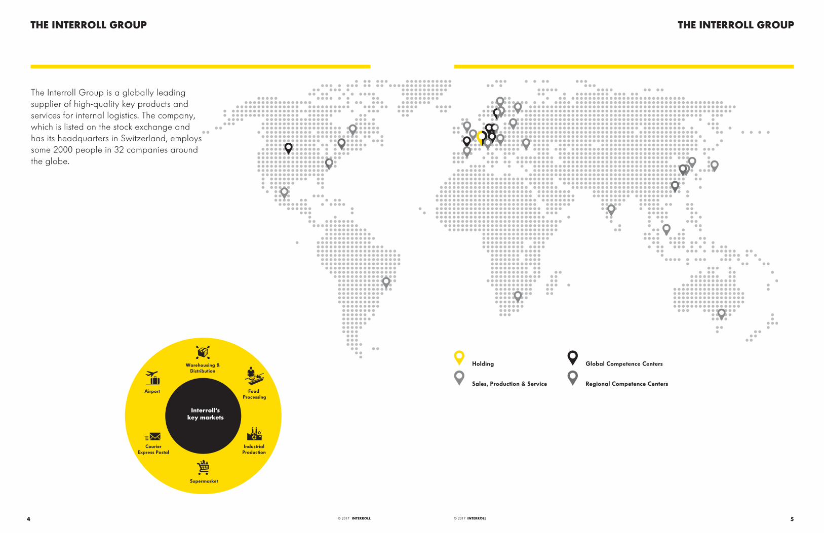
Holding Global Competence Centers
Sales, Production & Service Regional Competence Centers
The Interroll Group is a globally leading supplier of high-quality key products and services for internal logistics. The company, which is listed on the stock exchange and has its headquarters in Switzerland, employs some 2000 people in 32 companies around the globe.
THE INTERROLL GROUP
Interroll‘skey markets
Warehousing &Distribution
Food Processing
Airport
CourierExpress Postal
IndustrialProduction
Supermarket
© 2017 INTERROLL 7
INTERROLL CORE PRODUCTS AND SOLUTIONS
6 © 2017 INTERROLL
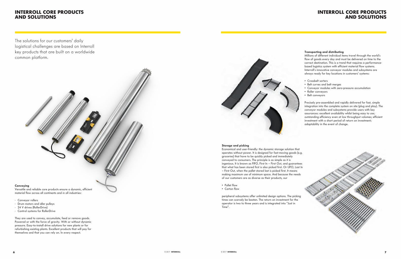
Transporting and distributingMillions of different individual items travel through the world’s flow of goods every day and must be delivered on time to the correct destination. This is a trend that requires a performance-based logistics system with efficient material flow systems. Interroll’s innovative conveyor modules and subsystems are always ready for key locations in customers' systems:
• Crossbelt sorters• Belt curves and belt merges• Conveyor modules with zero-pressure accumulation• Roller conveyors• Belt conveyors
Precisely pre-assembled and rapidly delivered for fast, simple integration into the complete system on site (plug and play). The conveyor modules and subsystems provide users with key assurances: excellent availability whilst being easy to use; outstanding efficiency even at low throughput volumes; efficient investment with a short period of return on investment; adaptability in the event of change.
Storage and pickingEconomical and user-friendly: the dynamic storage solution that operates without power. It is designed for fast-moving goods (e.g. groceries) that have to be quickly picked and immediately conveyed to consumers. The principle is as simple as it is ingenious. It is known as FIFO, First In – First Out, and guarantees that what has been stored first is also picked first. Or LIFO, Last In – First Out, when the pallet stored last is picked first. It means making maximum use of minimum space. And because the needs of our customers are as diverse as their products, our
• Pallet flow• Carton flow
peripheral subsystems offer unlimited design options. The picking times can scarcely be beaten. The return on investment for the operator is two to three years and is integrated into "Just in Time".
INTERROLL CORE PRODUCTS AND SOLUTIONS
The solutions for our customers' daily logistical challenges are based on Interroll key products that are built on a worldwide common platform.
ConveyingVersatile and reliable core products ensure a dynamic, efficient material flow across all continents and in all industries:
· Conveyor rollers· Drum motors and idler pulleys· 24 V drives (RollerDrive)· Control systems for RollerDrive
They are used to convey, accumulate, feed or remove goods. Powered or with the force of gravity. With or without dynamic pressure. Easy-to-install drive solutions for new plants or for refurbishing existing plants. Excellent products that will pay for themselves and that you can rely on. In every respect.

© 2017 INTERROLL 9
THE HIGHLY EFFICIENT BELT DRIVE
8 © 2017 INTERROLL
Compact, robust and absolutely hygienicSince the drum motor is installed directly in the frame of the conveyor belt in a space-saving way, the transport capacity is maximized given the same base area. Positive side effect: Elegantly designed conveyor belts with evenly distributed weights. The installation or replacement of a drum motor is generally simple and quick using the plug-and-play principle, because only a few components have to be installed - thus saving time and money. In food processing, perfect hygiene and good cleaning options are especially important: This is where the drum motor scores big with its encapsulated design made of stainless steel.
Proven principle, efficient driveIn principle, drum motors are energy-efficient because they directly drive the conveyor belt. In addition, they are practically maintenance-free and extremely wear-resistant, thereby significantly reducing the operating costs of the conveyor system and the risk of standstills or breakdowns. By the way: High-quality sealing systems ensure that a drum motor will also run reliably in aggressive environments.The Interroll synchronous drum motors have a very low power loss of only 9 %. The planetary gear box made of steel transfers 92 − 95 % of the power directly to the conveyor. They are especially suited to applications where a high-torque, dynamic drive, a wide speed range, or high duty cycles are necessary.
All-rounder with a broad application rangeDrum motor applications are varied: When used in friction-driven belts, the motor is cooled directly via the belt tensioned over the drum shell. Modular plastic belts are not tensioned; in this case, the drive is form-fit via sprockets or a profile lagging. Solid homogeneous belts are also positive driven, whereby a profile on the underside of the belt engages in a drum profile made of hygienically certified PU. But it also works entirely without a belt and the drum motor transports the material directly.
THE HIGHLY EFFICIENT BELT DRIVE

© 2017 INTERROLL 11
INTERROLL PLATFORM FOR DRUM MOTORS
10 © 2017 INTERROLL
Flexibility and robustness make the difference
More performance, more configurabilityThe broad range of services for the motors covers all conceivable uses in the food industry, intralogistics and manufacturing. All motors are optimized for their application, giving planning personnel the freedom to choose between synchronous and asynchronous designs.
Tested quality, innovative technology All motor components are standardized, tested, and approved in elaborate testing. Modularized motor types have been developed for all current applications; they are quickly available and contribute to minimizing costs.
More hygienicAll Interroll Drum Motors of the new generation meet the highest standards of hygiene according to IP69k. This gives users the assurance that the cleaning process meets the highest standard.
Fewer breakdownsA stable planetary gear train is enough for a high torque in all motors, holds up against bending, and resists overloads and impact loads. The result is safer, more reliable operation.
Lower costs, more service The clever plug-and-play wiring solution and simple installation, assembly and maintenance ensure noticeable savings in time and costs, as well as reduced downtimes of the conveyor system. Replacement parts available worldwide through Interroll and service partners make repairs easy and offer a faster, better service.
More stabilityThe strong 30 mm shaft and the larger ball bearings on Interroll’s new drum motors allow significantly higher belt tensions. It provides a safety net even in cases of a defective belt tracking or overtensioned conveyor belts.
DM 0080 DM 0080 DM 0080 DM 0080 DM 0080
Motor technology Asynchronous Asynchronous Asynchronous Asynchronous Synchronous
No. phase 3 phase 3 phase 1 phase 1 phase
Diameter 3.21" 3.21" 3.21" 3.21" 3.21"
Gear material Steel Technopolymer Steel Technopolymer Steel
Rated power .054 − .188 HP .054 − .100 HP .034 − .148 HP .034 − .148 HP .194 − .570 HP
Rated torque .8 − 35.3 lbf-ft* 1.9 − 12.0 lbf-ft* .5 − 23.1 lbf-ft 2.7 − 12.6 lbf-ft 1.24 − 38.35 lbf-ft
Max. belt pull 264 lbf* 90 lbf* 173 lbf* 94 lbf* 287 lbf
Speed of the shell 8 − 612 fpm* 17 − 220 fpm* 10 − 490 fpm* 10 − 177 fpm* 16 − 535 fpm
Drum width (FW) 7.56 − 43.31 in 9.13 − 43.31 in 7.56 − 43.31 in 9.13 − 43.31 in 7.28 − 43.31 in
Friction-driven belt l l l l l
Positive drive belt l − − − l
Without belt l − − − l
* At 60 Hz
INTERROLL PLATFORM FOR DRUM MOTORS
Practice-oriented, scalable, and thought out in detail
The new drum motor platform from Interroll combines the different motor concepts in a single design and makes it easy for customers to build their own and completely individual conveyor system. Since all motors have the same shafts, the number of different parts from the original equipment manufacturer is reduced and
conveyor construction is significantly easier. The broad speed spectrum covers all imaginable applications. The clever plug-and-play solution makes installation easier. Each motor is approved, tested, and modularized so that it can be produced and delivered around the world in the shortest amount of time.
DRUM MOTORDM 0080
DRUM MOTORDM 0080
13© 2017 INTERROLL12 © 2017 INTERROLL
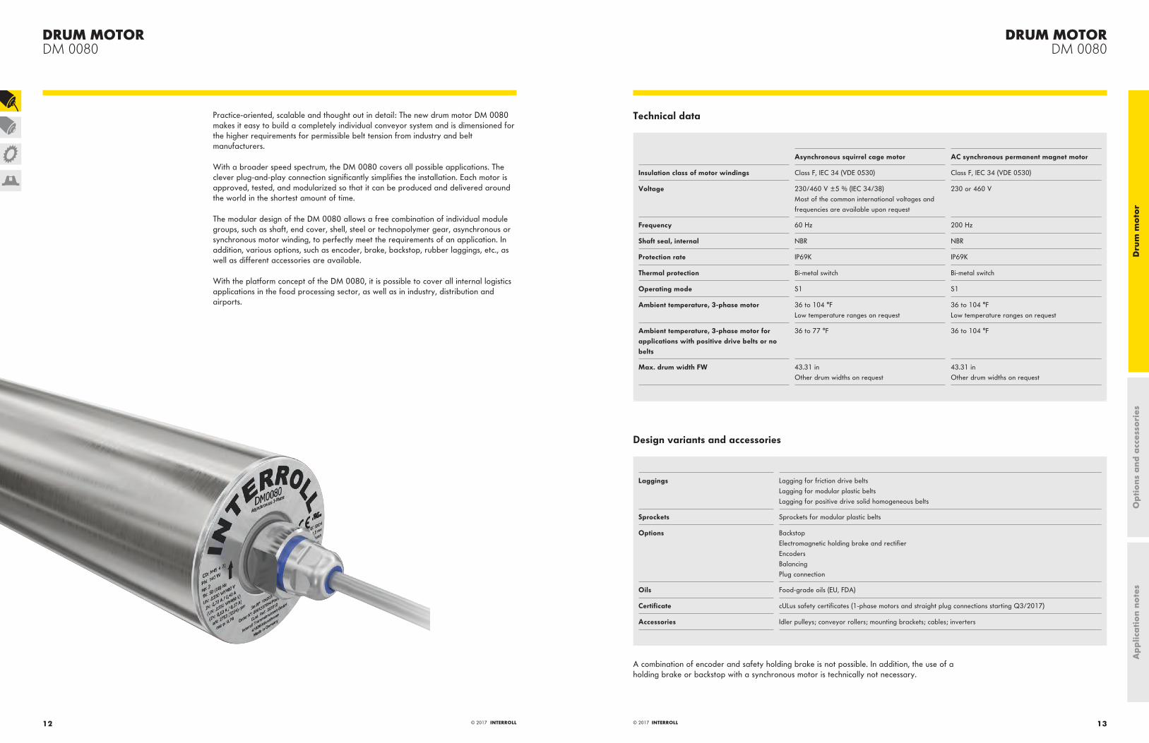
Practice-oriented, scalable and thought out in detail: The new drum motor DM 0080 makes it easy to build a completely individual conveyor system and is dimensioned for the higher requirements for permissible belt tension from industry and belt manufacturers.
With a broader speed spectrum, the DM 0080 covers all possible applications. The clever plug-and-play connection significantly simplifies the installation. Each motor is approved, tested, and modularized so that it can be produced and delivered around the world in the shortest amount of time.
The modular design of the DM 0080 allows a free combination of individual module groups, such as shaft, end cover, shell, steel or technopolymer gear, asynchronous or synchronous motor winding, to perfectly meet the requirements of an application. In addition, various options, such as encoder, brake, backstop, rubber laggings, etc., as well as different accessories are available.
With the platform concept of the DM 0080, it is possible to cover all internal logistics applications in the food processing sector, as well as in industry, distribution and airports.
Technical data
Asynchronous squirrel cage motor AC synchronous permanent magnet motor
Insulation class of motor windings Class F, IEC 34 (VDE 0530) Class F, IEC 34 (VDE 0530)
Voltage 230/460 V ±5 % (IEC 34/38) Most of the common international voltages and frequencies are available upon request
230 or 460 V
Frequency 60 Hz 200 Hz
Shaft seal, internal NBR NBR
Protection rate IP69K IP69K
Thermal protection Bi-metal switch Bi-metal switch
Operating mode S1 S1
Ambient temperature, 3-phase motor 36 to 104 °FLow temperature ranges on request
36 to 104 °FLow temperature ranges on request
Ambient temperature, 3-phase motor for applications with positive drive belts or no belts
36 to 77 °F 36 to 104 °F
Max. drum width FW 43.31 inOther drum widths on request
43.31 inOther drum widths on request
Design variants and accessories
Laggings Lagging for friction drive beltsLagging for modular plastic beltsLagging for positive drive solid homogeneous belts
Sprockets Sprockets for modular plastic belts
Options BackstopElectromagnetic holding brake and rectifierEncodersBalancingPlug connection
Oils Food-grade oils (EU, FDA)
Certificate cULus safety certificates (1-phase motors and straight plug connections starting Q3/2017)
Accessories Idler pulleys; conveyor rollers; mounting brackets; cables; inverters
A combination of encoder and safety holding brake is not possible. In addition, the use of a holding brake or backstop with a synchronous motor is technically not necessary.
Ap
plic
ati
on
note
sO
pti
ons
and
acc
esso
ries
Dru
m m
oto
r
DRUM MOTORDM 0080
DRUM MOTORDM 0080
15© 2017 INTERROLL© 2017 INTERROLL14
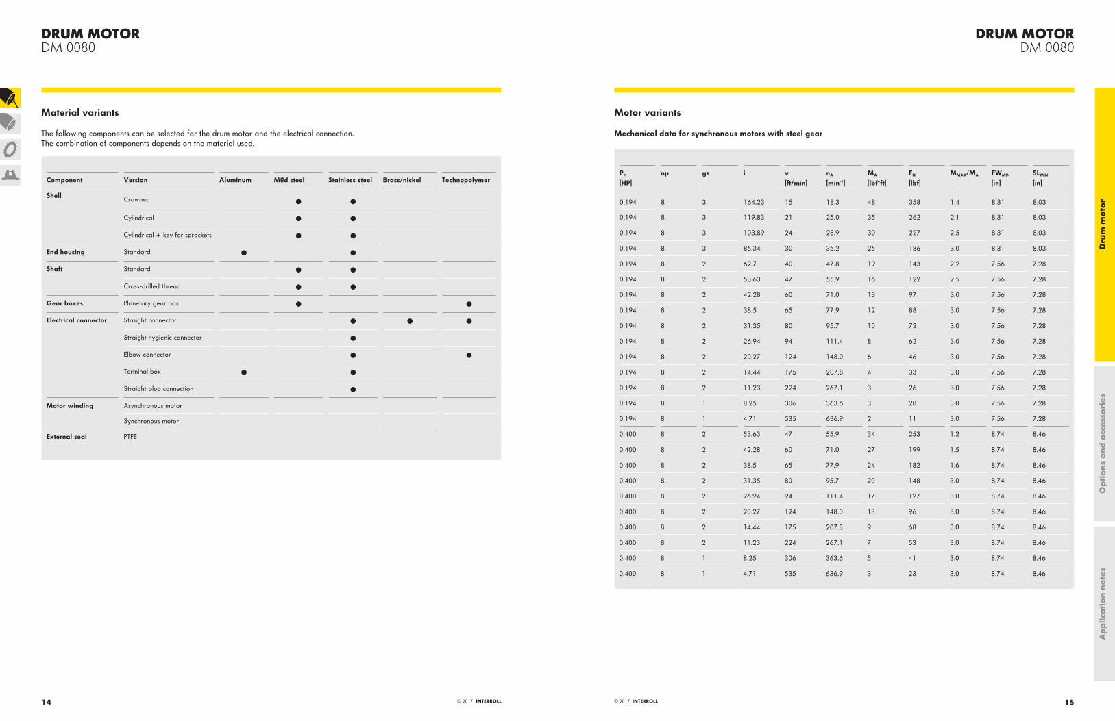
Material variants
The following components can be selected for the drum motor and the electrical connection. The combination of components depends on the material used.
Component Version Aluminum Mild steel Stainless steel Brass/nickel Technopolymer
Shell Crowned l l
Cylindrical l l
Cylindrical + key for sprockets l l
End housing Standard l l
Shaft Standard l l
Cross-drilled thread l l
Gear boxes Planetary gear box l l
Electrical connector Straight connector l l l
Straight hygienic connector l
Elbow connector l l
Terminal box l l
Straight plug connection l
Motor winding Asynchronous motor
Synchronous motor
External seal PTFE
Motor variants
Mechanical data for synchronous motors with steel gear
PN
[HP]np gs i v
[ft/min]nA
[min-1]MA
[lbf*ft]FN
[lbf]MMAX/MA FWMIN
[in]SLMIN
[in]
0.194 8 3 164.23 15 18.3 48 358 1.4 8.31 8.03
0.194 8 3 119.83 21 25.0 35 262 2.1 8.31 8.03
0.194 8 3 103.89 24 28.9 30 227 2.5 8.31 8.03
0.194 8 3 85.34 30 35.2 25 186 3.0 8.31 8.03
0.194 8 2 62.7 40 47.8 19 143 2.2 7.56 7.28
0.194 8 2 53.63 47 55.9 16 122 2.5 7.56 7.28
0.194 8 2 42.28 60 71.0 13 97 3.0 7.56 7.28
0.194 8 2 38.5 65 77.9 12 88 3.0 7.56 7.28
0.194 8 2 31.35 80 95.7 10 72 3.0 7.56 7.28
0.194 8 2 26.94 94 111.4 8 62 3.0 7.56 7.28
0.194 8 2 20.27 124 148.0 6 46 3.0 7.56 7.28
0.194 8 2 14.44 175 207.8 4 33 3.0 7.56 7.28
0.194 8 2 11.23 224 267.1 3 26 3.0 7.56 7.28
0.194 8 1 8.25 306 363.6 3 20 3.0 7.56 7.28
0.194 8 1 4.71 535 636.9 2 11 3.0 7.56 7.28
0.400 8 2 53.63 47 55.9 34 253 1.2 8.74 8.46
0.400 8 2 42.28 60 71.0 27 199 1.5 8.74 8.46
0.400 8 2 38.5 65 77.9 24 182 1.6 8.74 8.46
0.400 8 2 31.35 80 95.7 20 148 3.0 8.74 8.46
0.400 8 2 26.94 94 111.4 17 127 3.0 8.74 8.46
0.400 8 2 20.27 124 148.0 13 96 3.0 8.74 8.46
0.400 8 2 14.44 175 207.8 9 68 3.0 8.74 8.46
0.400 8 2 11.23 224 267.1 7 53 3.0 8.74 8.46
0.400 8 1 8.25 306 363.6 5 41 3.0 8.74 8.46
0.400 8 1 4.71 535 636.9 3 23 3.0 8.74 8.46
Ap
plic
ati
on
note
sO
pti
ons
and
acc
esso
ries
Dru
m m
oto
r

DRUM MOTORDM 0080
DRUM MOTORDM 0080
17© 2017 INTERROLL© 2017 INTERROLL16
PN
[HP]np gs i v
[ft/min]nA
[min-1]MA
[lbf*ft]FN
[lbf]MMAX/MA FWMIN
[in]SLMIN
[in]
0.570 8 2 38.5 65 77.9 35 258 1.6 7.56 7.28
0.570 8 2 31.35 80 95.7 28 210 2.6 9.92 9.65
0.570 8 2 26.94 94 111.4 24 181 3.0 9.92 9.65
0.570 8 2 20.27 124 148.0 18 136 3.0 9.92 9.65
0.570 8 2 14.44 175 207.8 13 97 3.0 9.92 9.65
0.570 8 2 11.23 224 267.1 10 75 3.0 9.92 9.65
0.570 8 1 8.25 306 363.6 8 58 2.5 9.92 9.65
0.570 8 1 4.71 535 636.9 4 33 3.0 9.92 9.65
PN = Rated power MA = Drum motor rated torquenp = Number of poles FN = Drum motor rated belt pullgs = Gear stages MMAX/MA = Ratio of max. acceleration torque to rated torquei = Speed ratio FWMIN = Minimum drum widthv = Speed SLMIN = Minimum shell lengthnA = Shell rated speed
Electrical data for synchronous motors
PN
[W]np UN
[V]IN
[A]I0
[A]IMAX
[A]fN
[Hz]η nN
[rpm]JR
[kgcm2]MN
[Nm]M0
[Nm]MMAX
[Nm]RM
[Ω]LSD
[mH]LSQ
[mH]ke
[V/krpm]Te
[ms]kTN
[Nm/A]USH
[V]
145 8 230 0.81 0.81 2.43 200 0.85 3000 0.14 0.46 0.46 1.38 21.6 45.60 53.70 41.57 4.97 0.57 25
145 8 400 0.47 0.47 1.41 200 0.83 3000 0.14 0.46 0.46 1.38 62.5 130.7 138.0 72.23 4.41 0.98 36
298 8 230 1.30 1.30 3.90 200 0.86 3000 0.28 0.95 0.95 2.85 10.2 27.80 29.30 47.46 5.75 0.73 19
298 8 400 0.78 0.78 2.34 200 0.87 3000 0.28 0.95 0.95 2.85 29.1 81.90 94.10 83.09 6.48 1.22 32
425 8 230 2.30 2.30 6.90 200 0.87 3000 0.42 1.35 1.35 4.05 5.66 16.26 19.42 45.81 6.86 0.59 19
425 8 400 1.32 1.32 3.96 200 0.86 3000 0.42 1.35 1.35 4.05 17.6 49.80 59.00 80.80 6.70 1.02 33
PN = Rated power MA = Drum motor rated torquenp = Number of poles FN = Drum motor rated belt pullgs = Gear stages MMAX/MA = Ratio of max. acceleration torque to rated torquei = Speed ratio FWMIN = Minimum drum widthv = Speed SLMIN = Minimum shell lengthnA = Shell rated speed
Ap
plic
ati
on
note
sO
pti
ons
and
acc
esso
ries
Dru
m m
oto
r

DRUM MOTORDM 0080
DRUM MOTORDM 0080
19© 2017 INTERROLL© 2017 INTERROLL18
Mechanical data for 3-phase asynchronous motor with steel gear
PN
[HP]np gs i v
[ft/min]nA
[min-1]MA
[lbf*ft]FN
[lbf]FWMIN
[in]SLMIN
[in]
0.054 4 3 164.23 8 7.8 25 187 8.62 8.35
0.054 4 3 119.83 12 10.7 18 136 8.62 8.35
0.054 4 3 103.89 13 12.3 16 118 8.62 8.35
0.054 4 3 85.34 16 15.0 13 97 8.62 8.35
0.054 4 2 62.70 22 20.4 10 75 7.87 7.60
0.054 4 2 53.63 26 23.8 9 64 7.87 7.60
0.054 4 2 42.28 33 30.2 7 50 7.87 7.60
0.054 4 2 38.50 36 33.2 6 46 7.87 7.60
0.054 4 2 31.35 44 40.8 5 37 7.87 7.60
0.054 4 2 26.94 52 47.4 4 32 7.87 7.60
0.054 4 2 20.27 69 63.0 3 24 7.87 7.60
0.054 4 2 14.44 96 88.5 2 17 7.87 7.60
0.054 4 2 11.23 124 113.8 2 13 7.87 7.60
0.054 4 1 8.25 169 154.9 1 10 7.87 7.60
0.054 4 1 4.71 296 271.3 1 6 7.87 7.60
0.101 2 3 164.23 18 16.2 23 168 8.62 8.35
0.101 2 3 119.83 24 22.2 16 123 8.62 8.35
0.101 2 3 103.89 28 25.6 14 106 8.62 8.35
0.101 2 3 85.34 34 31.2 12 87 8.62 8.35
0.101 2 2 62.70 46 42.4 9 67 7.87 7.6
0.101 2 2 53.63 54 49.6 8 58 7.87 7.6
0.101 2 2 42.28 68 62.9 6 45 7.87 7.6
0.101 2 2 38.50 75 69.1 6 41 7.87 7.6
0.101 2 2 31.35 92 84.8 4 34 7.87 7.6
0.101 2 2 26.94 107 98.7 4 29 7.87 7.6
0.101 2 2 20.27 142 131.2 3 22 7.87 7.6
0.101 2 2 14.44 200 184.1 2 15 7.87 7.6
0.101 2 2 11.23 257 236.8 2 12 7.87 7.6
0.101 2 1 8.25 349 322.3 1 9 7.87 7.6
0.101 2 1 4.71 612 564.5 1 5 7.87 7.6
0.107 4 3 119.83 12 10.9 35 264 10.59 10.31
0.107 4 3 103.89 13 12.6 31 229 10.59 10.31
PN
[HP]np gs i v
[ft/min]nA
[min-1]MA
[lbf*ft]FN
[lbf]FWMIN
[in]SLMIN
[in]
0.107 4 3 85.34 16 15.3 25 188 10.59 10.31
0.107 4 2 62.70 22 20.9 19 144 9.84 9.57
0.107 4 2 53.63 26 24.4 17 124 9.84 9.57
0.107 4 2 42.28 33 30.9 13 97 9.84 9.57
0.107 4 2 38.50 36 34.0 12 89 9.84 9.57
0.107 4 2 31.35 44 41.7 10 72 9.84 9.57
0.107 4 2 26.94 52 48.6 8 62 9.84 9.57
0.107 4 2 20.27 69 64.5 6 47 9.84 9.57
0.107 4 2 14.44 96 90.6 4 33 9.84 9.57
0.107 4 2 11.23 124 116.5 3 26 9.84 9.57
0.107 4 1 8.25 169 158.5 3 20 9.84 9.57
0.107 4 1 4.71 296 277.7 2 11 9.84 9.57
0.188 2 3 119.83 24 23.0 30 223 10.59 10.31
0.188 2 3 103.89 28 26.5 26 193 10.59 10.31
0.188 2 3 85.34 34 32.3 21 159 10.59 10.31
0.188 2 2 62.70 46 43.9 16 122 9.84 9.57
0.188 2 2 53.63 54 51.3 14 104 9.84 9.57
0.188 2 2 42.28 68 65.1 11 82 9.84 9.57
0.188 2 2 38.50 75 71.5 10 75 9.84 9.57
0.188 2 2 31.35 92 87.8 8 61 9.84 9.57
0.188 2 2 26.94 107 102.2 7 52 9.84 9.57
0.188 2 2 20.27 142 135.8 5 39 9.84 9.57
0.188 2 2 14.44 200 190.7 4 28 9.84 9.57
0.188 2 2 11.23 257 245.1 3 22 9.84 9.57
0.188 2 1 8.25 349 333.7 2 17 9.84 9.57
0.188 2 1 4.71 612 584.5 1 10 9.84 9.57
For applications with positive driven belts or applications without belt, the power must be reduced by 17 %.
PN = Rated power nA = Shell rated speednp = Number of poles MA = Drum motor rated torquegs = Gear stages FN = Drum motor rated belt pulli = Speed ratio FWMIN = Minimum drum widthv = Speed SLMIN = Minimum shell length
Ap
plic
ati
on
note
sO
pti
ons
and
acc
esso
ries
Dru
m m
oto
r

DRUM MOTORDM 0080
DRUM MOTORDM 0080
21© 2017 INTERROLL© 2017 INTERROLL20
Mechanical data for 3-phase asynchronous motor with technopolymer gear
PN
[HP]np gs i v
[ft/min]nA
[min-1]MA
[lbf*ft]FN
[lbf]FWMIN
[in]SLMIN
[in]
0.054 4 3 78.55 18 16.3 12 89 9.41 9.13
0.054 4 3 71.56 19 17.9 11 81 9.41 9.13
0.054 4 3 63.51 22 20.1 10 72 9.41 9.13
0.054 4 3 52.92 26 24.1 8 60 9.41 9.13
0.054 4 3 48.79 29 26.2 7 56 9.41 9.13
0.054 4 3 43.3 32 29.5 7 49 9.41 9.13
0.054 4 2 19.2 73 66.6 3 23 9.41 9.13
0.054 4 2 16 87 79.9 3 19 9.41 9.13
0.054 4 2 13.09 106 97.6 2 16 9.41 9.13
0.101 2 3 78.55 37 33.9 11 80 9.41 9.13
0.101 2 3 71.56 40 37.2 10 73 9.41 9.13
0.101 2 3 63.51 45 41.9 9 65 9.41 9.13
0.101 2 3 52.92 54 50.2 7 54 9.41 9.13
0.101 2 3 48.79 59 54.5 7 50 9.41 9.13
0.101 2 3 43.3 67 61.4 6 44 9.41 9.13
0.101 2 2 19.2 150 138.5 3 21 9.41 9.13
0.101 2 2 16 180 166.2 2 17 9.41 9.13
0.101 2 2 13.09 220 203.1 2 14 9.41 9.13
For applications with positive driven belts or applications without belt, this combination of motor and gear box is not recommended.
PN = Rated power nA = Shell rated speednp = Number of poles MA = Drum motor rated torquegs = Gear stages FN = Drum motor rated belt pulli = Speed ratio FWMIN = Minimum drum widthv = Speed SLMIN = Minimum shell length
Electrical data for 3-phase asynchronous motor
PN
[W]np nN
[min-1]fN
[Hz]UN
[V]IN
[A]cosφ η JR
[kgcm2]IS/IN MS/MN MP/MN MB/MN MN
[Nm]RM
[Ω]USHΔ
[V]USHY
[V]
40 4 1555 60 230 0.33 0.72 0.43 0.67 1.89 1.34 1.34 1.43 0.25 294.5 34.99 −
40 4 1644 60 460 0.21 0.61 0.4 0.67 1.98 1.85 1.85 2.08 0.23 294.5 − 56.59
75 2 3248 60 230 0.37 0.85 0.6 0.67 3.00 1.54 1.54 1.68 0.22 164.4 25.85 −
75 2 3376 60 460 0.21 0.73 0.61 0.67 3.52 2.03 2.03 2.39 0.21 164.4 − 37.80
80 4 1571 60 230 0.55 0.69 0.53 1.25 2.17 1.42 1.42 1.55 0.49 132.5 25.14 −
80 4 1658 60 460 0.34 0.57 0.51 1.25 2.40 2.09 2.09 2.25 0.46 132.5 − 38.52
140 2 3354 60 230 0.63 0.81 0.69 1.25 3.84 1.75 1.75 1.91 0.40 72.7 18.55 −
140 2 3430 60 460 0.37 0.69 0.68 1.25 4.45 2.48 2.48 2.67 0.39 72.7 − 27.84
PN = Rated power IS/IN = Ratio of startup current - rated currentnP = Number of poles MS/MN = Ratio of startup torque - rated torquenN = Rated speed of rotor MB/MN = Ratio of pull-out torque - rated torquefN = Rated frequency MP/MN = Ratio of pull-up torque - rated torqueUN = Rated voltage MN = Rated torque of rotorIN = Rated current RM = Branch resistancecosφ = Power factor USHΔ = Heater voltage in delta connectionη = Efficiency USHY = Heater voltage in star connectionJR = Rotor moment of inertia
Ap
plic
ati
on
note
sO
pti
ons
and
acc
esso
ries
Dru
m m
oto
r

DRUM MOTORDM 0080
DRUM MOTORDM 0080
23© 2017 INTERROLL© 2017 INTERROLL22
Mechanical data for 1-phase asynchronous motor with steel gear
PN
[HP]np gs i v
[ft/min]nA
[1/min]MA
[lbf*ft]FN
[lbf]FWMIN
[in]SLMIN
[in]
0.034 4 3 119.83 11 11.0 10.9 82 10.59 10.31
0.034 4 3 103.89 13 12.7 9.5 71 10.59 10.31
0.034 4 3 85.34 16 15.5 7.8 58 10.59 10.31
0.034 4 2 62.7 21 21.1 6 45 9.84 9.57
0.034 4 2 53.63 25 24.6 5.1 38 9.84 9.57
0.034 4 2 42.28 31 31.2 4 30 9.84 9.57
0.034 4 2 38.5 35 34.3 3.7 28 9.84 9.57
0.034 4 2 31.35 42 42.1 3 22 9.84 9.57
0.034 4 2 26.94 49 49.0 2.6 19 9.84 9.57
0.034 4 2 20.27 66 65.1 1.9 14 9.84 9.57
0.034 4 2 14.44 92 91.4 1.4 10 9.84 9.57
0.034 4 2 11.23 118 117.5 1.1 8 9.84 9.57
0.034 4 1 8.25 161 160.0 0.8 6 9.84 9.57
0.034 4 1 4.71 282 280.3 0.5 4 9.84 9.57
0.101 2 3 119.83 23 22.9 15.8 118 10.59 10.31
0.101 2 3 103.89 27 26.5 13.7 103 10.59 10.31
0.101 2 3 85.34 32 32.2 11.3 84 10.59 10.31
0.101 2 2 62.7 44 43.9 8.7 65 9.84 9.57
0.101 2 2 53.63 52 51.3 7.4 55 9.84 9.57
0.101 2 2 42.28 66 65.0 5.8 44 9.84 9.57
0.101 2 2 38.5 72 71.4 5.3 40 9.84 9.57
0.101 2 2 31.35 88 87.7 4.3 32 9.84 9.57
0.101 2 2 26.94 103 102.1 3.7 28 9.84 9.57
0.101 2 2 20.27 137 135.7 2.8 21 9.84 9.57
0.101 2 2 14.44 192 190.4 2 15 9.84 9.57
0.101 2 2 11.23 247 244.9 1.6 12 9.84 9.57
0.101 2 1 8.25 336 333.3 1.2 9 9.84 9.57
0.101 2 1 4.71 588 583.9 0.7 5 9.84 9.57
0.114 2 3 119.83 23 22.9 18.2 136 10.59 10.31
0.114 2 3 103.89 27 26.5 15.8 118 10.59 10.31
0.114 2 3 85.34 32 32.2 13 97 10.59 10.31
0.114 2 2 62.7 44 43.9 10 75 9.84 9.57
PN
[HP]np gs i v
[ft/min]nA
[1/min]MA
[lbf*ft]FN
[lbf]FWMIN
[in]SLMIN
[in]
0.114 2 2 53.63 52 51.3 9 64 9.84 9.57
0.114 2 2 42.28 66 65.0 7 50 9.84 9.57
0.114 2 2 38.5 72 71.4 6 46 9.84 9.57
0.114 2 2 31.35 88 87.7 5 37 9.84 9.57
0.114 2 2 26.94 103 102.1 4 32 9.84 9.57
0.114 2 2 20.27 137 135.7 3 24 9.84 9.57
0.114 2 2 14.44 192 190.4 2 17 9.84 9.57
0.114 2 2 11.23 247 244.9 2 13 9.84 9.57
0.114 2 1 8.25 336 333.3 1 10 9.84 9.57
0.114 2 1 4.71 588 583.9 1 6 9.84 9.57
0.148 2 3 119.83 23 23.0 23 173 10.59 10.31
0.148 2 3 103.89 27 26.5 20 150 10.59 10.31
0.148 2 3 85.34 32 32.2 17 123 10.59 10.31
0.148 2 2 62.7 44 43.9 13 95 9.84 9.57
0.148 2 2 53.63 52 51.3 11 81 9.84 9.57
0.148 2 2 42.28 66 65.0 9 64 9.84 9.57
0.148 2 2 38.5 72 71.4 8 58 9.84 9.57
0.148 2 2 31.35 88 87.7 6 47 9.84 9.57
0.148 2 2 26.94 103 102.1 5 41 9.84 9.57
0.148 2 2 20.27 137 135.7 4 31 9.84 9.57
0.148 2 2 14.44 192 190.5 3 22 9.84 9.57
0.148 2 2 11.23 247 244.9 2 17 9.84 9.57
0.148 2 1 8.25 336 333.4 2 13 9.84 9.57
0.148 2 1 4.71 588 583.9 1 8 9.84 9.57
For applications with positive driven belts or applications without belt, this combination of motor and gear box is not recommended.
PN = Rated power MA = Drum motor rated torquenp = Number of poles FN = Drum motor rated belt pullgs = Gear stages MMAX/MA = Ratio of max. acceleration torque to rated torquei = Speed ratio FWMIN = Minimum drum widthv = Speed SLMIN = Minimum shell lengthnA = Shell rated speed A
pp
lica
tio
n no
tes
Op
tio
ns a
nd a
cces
sori
esD
rum
mo
tor

DRUM MOTORDM 0080
DRUM MOTORDM 0080
25© 2017 INTERROLL© 2017 INTERROLL24
Mechanical data for 1-phase asynchronous motor with technopolymer gear
PN
[HP]np gs i v
[ft/min]nA
[1/min]MA
[lbf*ft]FN
[lbf]FWMIN
[in]SLMIN
[in]
0.034 4 3 115.2 12 11.5 10.5 78 11.3 11.02
0.034 4 3 96 14 13.8 8.7 65 11.3 11.02
0.034 4 3 78.55 17 16.8 7.1 53 11.3 11.02
0.034 4 3 71.56 19 18.4 6.5 49 11.3 11.02
0.101 2 3 96 29 28.6 12.6 94 11.3 11.02
0.101 2 3 78.55 35 35 10.3 77 11.3 11.02
0.101 2 3 71.56 39 38.4 9.4 70 11.3 11.02
0.101 2 3 63.51 44 43.3 8.4 62 11.3 11.02
0.114 2 3 78.55 35 35 11.9 89 11.3 11.02
0.114 2 3 71.56 39 38.4 10.9 81 11.3 11.02
0.114 2 3 63.51 44 43.3 9.6 72 11.3 11.02
0.148 2 3 63.51 44 43.3 12.2 91 11.3 11.02
0.148 2 3 52.92 52 52 10.1 76 11.3 11.02
0.148 2 3 48.79 57 56.4 9.4 70 11.3 11.02
0.148 2 3 43.3 64 63.5 8.3 62 11.3 11.02
0.148 2 2 19.2 144 143.2 3.9 29 11.3 11.02
0.148 2 2 16 173 171.9 3.2 24 11.3 11.02
0.148 2 2 13.09 212 210.1 2.7 20 11.3 11.02
For applications with positive driven belts or applications without belt, this combination of motor and gear box is not recommended.
PN = Rated power MA = Drum motor rated torquenp = Number of poles FN = Drum motor rated belt pullgs = Gear stages MMAX/MA = Ratio of max. acceleration torque to rated torquei = Speed ratio FWMIN = Minimum drum widthv = Speed SLMIN = Minimum shell lengthnA = Shell rated speed
Electrical data for 1-phase asynchronous motor
PN
[W]np UN
[V]IN
[A]cosφ η JR
[kgcm2]IS/IN MS/MN MB/MN MP/MN RM
[Ω]USH ~
[V DC]CR
[µF]
25 4 230 0.39 1.00 0.28 1.2 2.2 1.11 1.37 1.11 150.0 44 3
50 2 230 0.54 1.00 0.4 0.9 3.1 0.94 1.71 0.94 82.0 33 3
75 2 230 0.68 1.00 0.48 1.0 3.2 0.74 1.37 0.74 66.0 34 4
85 2 230 0.73 0.98 0.53 1.3 5.2 0.93 1.6 0.93 52.0 28 6
110 2 230 0.94 1.00 0.51 1.2 2.0 0.73 1.15 0.73 51.0 36 8
PN = Rated power IS/IN = Ratio of startup current - rated currentnp = Number of poles MS/MN = Ratio of startup torque - rated torqueUN = Rated voltage MB/MN = Ratio of pull-out torque - rated torqueIN = Rated current MP/MN = Ratio of pull-up torque - rated torquecosφ = Power factor RM = Branch resistanceη = Efficiency USH ~ = Heater voltage for DC unitsJR = Rotor moment of inertia CR = Capacitor size
Ap
plic
ati
on
note
sO
pti
ons
and
acc
esso
ries
Dru
m m
oto
r

DRUM MOTORDM 0080
DRUM MOTORDM 0080
27© 2017 INTERROLL© 2017 INTERROLL26
Belt tension diagrams
Belt tension depending on drum width
0
1000
2000
3000
4000
5000
6000
7000
8000
500 600 700 800 900 1000 1100 1200
TE [N
]
FW [mm]
Belt tension depending on rated speed of shell
05 10 20 40 80 160 320 640
nA [1/min]
8000
7000
6000
5000
4000
3000
2000
1000
TE [N
]
Note: The correct value for the maximum permissible belt tension is determined from the speed of the drum motor. When selecting the motor, also check whether the maximum permissible TE value fits the desired drum width (FW).
TE = Belt tensionnA = Shell rated speedFW = Drum width
Dimensions
Drum motor
AGL
ELC C
HH
D
A-A
FA
A
øB øA
SL=FW-2xP
FW
P P
Type A[mm]
B[mm]
C[mm]
D[mm]
F[mm]
H[mm]
P[mm]
SL[mm]
EL[mm]
AGL[mm]
DM 0080 crowned 81.5 80.5 12.5 30 25 6 3.5 FW - 7 FW + 5 FW + 30
81.5 80.5 12.5 25* 20 6 3.5 FW - 7 FW + 5 FW + 30
81.5 80.5 12.5 17* 13.5 6 3.5 FW - 7 FW + 5 FW + 30
DM 0080 cylindrical 81 81 12.5 30 25 6 3.5 FW - 7 FW + 5 FW + 30
81 81 12.5 25* 20 6 3.5 FW - 7 FW + 5 FW + 30
81 81 12.5 17* 13.5 6 3.5 FW - 7 FW + 5 FW + 30
DM 0080 cylindrical + key 81.7 81.7 12.5 30 25 6 3.5 FW - 7 FW + 5 FW + 30
81.7 81.7 12.5 25* 20 6 3.5 FW - 7 FW + 5 FW + 30
81.7 81.7 12.5 17* 13.5 6 3.5 FW - 7 FW + 5 FW + 30
Ap
plic
ati
on
note
sO
pti
ons
and
acc
esso
ries
Dru
m m
oto
r

DRUM MOTORDM 0080
DRUM MOTORDM 0080
29© 2017 INTERROLL© 2017 INTERROLL28
Cable connections
ø2318
Fig.: Straight hygienic connector, IP69k stainless steel
27
26
27
24
Fig.: Straight connector, brass or stainless steel
25
18
25
22
Fig.: Straight EMC connector, brass or stainless steel
27
26
27
24
Fig.: Straight connector for encoder, brass or stainless steel
ø201.5
Fig.: Straight connector, shaft cap made of PU
20 20
10
22 32
Fig.: Elbow connector, Technopolymer
ø30
24
17.5
Fig.: Elbow connector, stainless steel, also for encoders
M20x 1,5
21
45
ø95
14
C-2 42
20°
Fig.: Terminal box, stainless steel
2217
65
M20x 1,5
ø95
14
46C-2
Fig.: Terminal box, aluminum
The minimum length of the drum motor with options increases as follows:
Brake: Min. FW + 59 mmFeedback device: Min. FW + 58 mmCable specification: page 35Available cable lengths: 1 m, 3 m, 5 m, 10 m
Ap
plic
ati
on
note
sO
pti
ons
and
acc
esso
ries
Dru
m m
oto
r

DRUM MOTORDM 0080
DRUM MOTORDM 0080
31© 2017 INTERROLL© 2017 INTERROLL30
Specification for straight plug connection (hygienic design)
The new plug connection is the ideal solution for a quick initial installation and significantly less maintenance effort. Connecting and disconnecting the cables to the motor is simple and can be performed safely and very quickly in just a few steps. Complete disassembly is not needed for motor maintenance or the replacement of a damaged cable. Only the pressing screw and the shell nipple must be loosened and completely unscrewed from the shaft end. Then the connector can easily be pulled out. The assembly is just as simple, in reverse order: The connector engages in the intended position. Then the shell nipple and pressing screw are screwed in and firmly tightened to the block.
Technical data
Shaft design Only for 30 mm shaft diameter and 25 mm width across flats
Materials Stainless steel, TPU seals
Connection Star/delta configuration with thermal controller contact (shield optional)
Cable lengths 1 m, 3 m, 5 m, 10 m
Delivery Cable not installed, screw components installed on cable
Electrical data According to DIN EN 61984
Voltage 230/460 V
Amperage Max. 5 A
Temperature range 36 to 104 °FLower temperatures on request
Protection rate IP69k after complete assembly
Hygiene requirement Suitable for cleaning with high-pressure cleaner
Directives CE certified, EHEDG certified, use of chemicals permissible according to ECOLAB
Mounting tool Open-end wrench 14 mm and 20 mm
The minimum length of the drum motor with plug connection increases by 59 mm.
Dimensions
18
C = 12,5; 20; 252,5
ø23
Fig.: Straight plug connection, qualified for hygienic cleaning, IP69k, stainless steel
min. 150
18
ø23
Fig.: Mounting dimensions with a mounting tool
Connection diagrams
Abbreviationsye/gn = yellow/green or = orangebn = brown vi = violetbk = black rd = redgy = gray wh = whitebu = blue FI = Frequency inverterTC = Thermal controller (thermal motor protection switch) NC = Not connectedBR = Electromagnetic brakes
Rotation
Note: The rotational direction of the drum motor is shown on the connection diagrams. The rotation indicated is correct when looking at the motor from the connection side.
Cable connections synchronous motor
1bn
2bk
3gyye/gn
3~ Motor
V1U1
T1 T2
5wh
4rd
L1 L3L2
TCintern
W1
FC
M90
Fig.: 3-phase, 4+2-core cable, winding for 1 voltage, star connection
Terminal box for synchronous motor
T1L3 T2L2L1
ye/gn5rd
L1 T1 T2 B1 B2Y
6wh
W1U1 V1
3~ Motor
TC
L2 L3
3gy
2bk
1bn
FC
intern
M91
Fig.: 3-phase, 4+2-core cable, winding for 1 voltage, star connection
Ap
plic
ati
on
note
sO
pti
ons
and
acc
esso
ries
Dru
m m
oto
r

DRUM MOTORDM 0080
DRUM MOTORDM 0080
33© 2017 INTERROLL© 2017 INTERROLL32
Cable connections 3-phase asynchronous motor
1bn
2bk
3gyye/gn
3~ Motor
V1U1
T1 T2
5wh
4rd
L1 L3L2
TCintern
W1
M30
Fig.: 3-phase, 4+2 core cable, winding for 1 voltage, delta connection
1bn
2bk
3gyye/gn
3~ Motor
V1U1
T1 T2
5wh
4rd
L1 L3L2
TCintern
W1
M31
Fig.: 3-phase, 4+2-core cable, winding for 1 voltage, star connection
DC
5or
6vi
T1 T2 AC
BR
internTC
U1 V1 W1 NC
ye/gn
L1 L2 L3 NC
3~ Motor
8wh
7rd
4bu
3gy
2bk
1bn
M30B
Fig.: With brake, 3-phase, 7+2 core cable, winding for 1 voltage, delta connection
DC
5or
6vi
T1 T2 AC
BR
internTC
U1 V1 W1 Y
ye/gn
L1 L2 L3 Y
3~ Motor
8wh
7rd
4bu
3gy
2bk
1bn
M31B
Fig.: With brake, 3-phase, 7+2 core cable, winding for 1 voltage, star connection
T2
8wh
7rd
W1 W2TC
ye/gn
U1 V2
L1 L3
U2V1
3~ Motor
L2 T1
6vi
5or
4bu
3gy
2bk
1bn
M34
Fig.: 3-phase, 7+2 core cable, winding for 2 voltages, delta connection
T2
8wh
7rd
W1 W2TC
ye/gn
U1 V2
L1 L3
U2V1
3~ Motor
L2 T1
6vi
5or
4bu
3gy
2bk
1bn
M34
Fig.: 3-phase, 7+2-core cable, winding for 2 voltages, star connection
T2
8wh
7rd
W1 W2TC
ye/gn
U1 V2
L1 L3
U2V1
3~ Motor
L2 T1
6vi
5or
4bu
3gy
2bk
1bn
M36
Fig.: 3-phase, 7+2 core cable, 2 speeds, delta connection
T2
8wh
7rd
W1 W2TC
ye/gn
U1 V2
L1 L3
U2V1
3~ Motor
L2 T1
6vi
5or
4bu
3gy
2bk
1bn
M36
Fig.: 3-phase, 7+2 core cable, 2 speeds, double-star connection
Terminal box 3-phase asynchronous motor
T1L3 T2L2L1
ye/gn7rd
L1 T1 T2 B1 B2Y
8wh
W1U1U2
V1
3~ Motor
W2 V2 TC
L2 L3
5or
3gy
4bu
2bk
6vi
1bn
M44
Fig.: 3-phase, winding for 2 voltages, delta connection
T1L3 T2L2L1
ye/gn7rd
L1 T1 T2 B1 B2Y
8wh
W1U1U2
V1
3~ Motor
W2V2
TC
L2 L3
5or
3gy
4bu
2bk
6vi
1bn
M45
Fig.: 3-phase, winding for 2 voltages, star connection
Ap
plic
ati
on
note
sO
pti
ons
and
acc
esso
ries
Dru
m m
oto
r
DRUM MOTORDM 0080
DRUM MOTORDM 0080
35© 2017 INTERROLL© 2017 INTERROLL34
T1L3 T2L2L1
ye/gn7rd
L1 T1 T2 B1 B2Y
8wh
W1U1 V1
internTC
L2 L3
3gy
2bk
1bn
AC
DC
6vi
5or
3~ Motor
BR
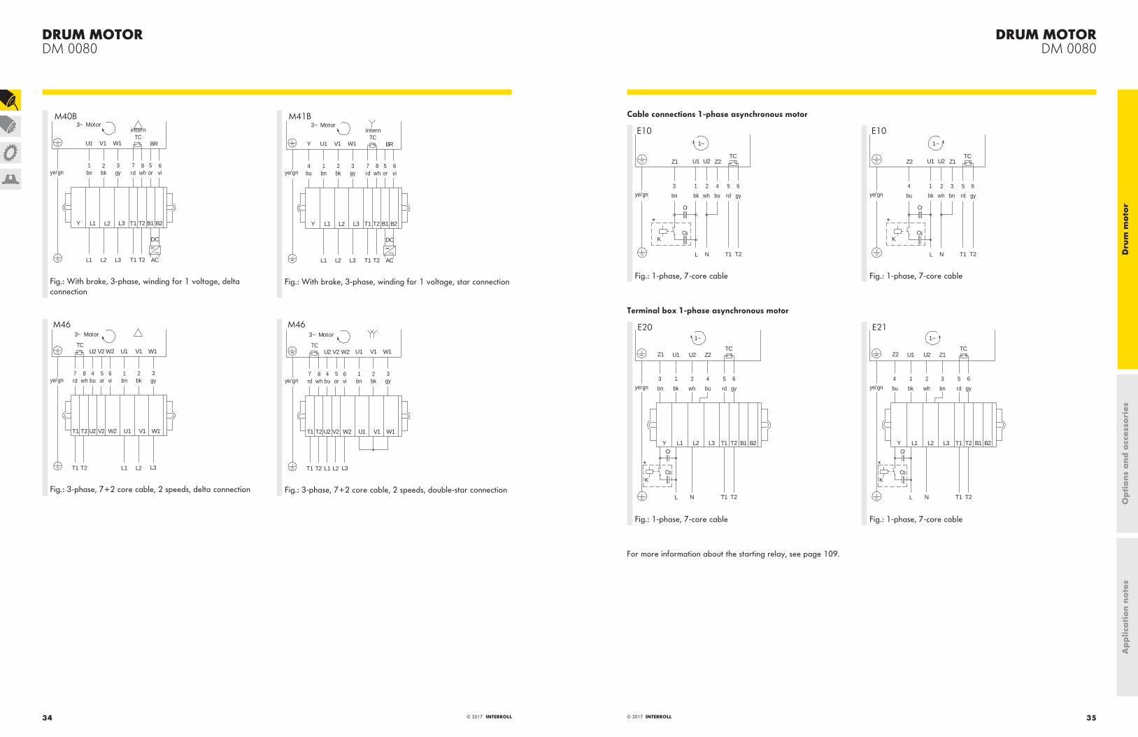
M40B
Fig.: With brake, 3-phase, winding for 1 voltage, delta connection
T1L3 T2L2L1
ye/gn7rd
L1 T1 T2 B1 B2Y
8wh
W1U1 V1
internTC
L2 L3
3gy
2bk
1bn
AC
DC
6vi
5or
3~ Motor
4bu
BRY
M41B
Fig.: With brake, 3-phase, winding for 1 voltage, star connection
T1 L3T2 L2L1
ye/gn7rd
U2T1 T2 V1 W1U1
8wh
W1U1U2 V1
3~ Motor
W2V2TC
V2 W2
5or
3gy
4bu
2bk
6vi
1bn
M46
Fig.: 3-phase, 7+2 core cable, 2 speeds, delta connection
T1 L3T2 L2L1
ye/gn7rd
U2T1 T2 V1 W1U1
8wh
W1U1U2 V1
3~ Motor
W2V2TC
V2 W2
5or
3gy
4bu
2bk
6vi
1bn
M46
Fig.: 3-phase, 7+2 core cable, 2 speeds, double-star connection
Cable connections 1-phase asynchronous motor
E10
Z1 Z2
ye/gn
T1
K
T2NL
U1 U2
1~
543
bn bu rd gybk wh
2 61
TC
Cr
Cs
Fig.: 1-phase, 7-core cable
E10
Z2 Z1
ye/gn
T1
K
T2NL
U1 U2
1~
534
bu bn rd gybk wh
2 61
TC
Cr
Cs
Fig.: 1-phase, 7-core cable
Terminal box 1-phase asynchronous motor
E20
Z1 Z2
ye/gn
T1
K
T2
T1 T2
NL
U1 U2
1~
543
bn bu rd gybk wh
2 61
TC
Cr
Cs
L1 B1 B2L2 L3Y
Fig.: 1-phase, 7-core cable
E21
Z2 Z1
ye/gn
T1
K
T2
T1 T2
NL
U1 U2
1~
534
bu bn rd gybk wh
2 61
TC
Cr
Cs
L1 B1 B2L2 L3Y
Fig.: 1-phase, 7-core cable
For more information about the starting relay, see page 109.
Ap
plic
ati
on
note
sO
pti
ons
and
acc
esso
ries
Dru
m m
oto
r

DRUM MOTORDM 0080
37© 2017 INTERROLL© 2017 INTERROLL36
Cable overview
To reduce EMC emissions, please use a shielded cable for operating the motor via a frequency inverter .
Article number 1107481 1107478 1107477 1107479 1107480 1107482 1000569
Main cores (number) 7 7 7 7 4 4 7
Cross section 0.5 mm2 0.75 mm2 0.75 mm2 0.75 mm2 0.75 mm2 0.75 mm2 0.75 mm2
Numeric code and color code
Numeric code + color code
Numeric code + color code
Numeric code + color code
Numeric code + color code
Numeric code + color code
Numeric code + color code
Numeric code + color code
Insulation conductors (main cores)
ETFE ETFE ETFE PP ETFE PP PVC
Data cores (number) 2 2 2 2 2 2 −
Cross section 0.5 mm2 0.5 mm2 0.5 mm2 0.5 mm2 0.5 mm2 0.5 mm2 −
Numeric code and color code
color code color code color code color code color code color code −
Insulation conductors (data cores)
ETFE ETFE ETFE PP ETFE PP −
Insulation of outer sheath PVC PVC PVC TPU PVC TPU PVC
Halogen-free No No No Yes No Yes No
Color of outer sheath Gray Gray Gray Gray Gray Gray Black
Shielded Copper-tinned Copper-tinned − Copper-tinned Copper-tinned Copper-tinned −
Outside diameter 7.7 ± 0.2 mm 8.4 ± 0.2 mm 7.3 ± 0.2 mm 8.4 ± 0.2 mm 7.6 ± 0.2 mm 7.6 ± 0.2 mm 7.15 ± 0.2 mm
Operating voltage 600 V 600 V 600 V 600 V 600 V 600 V 300/500 V
Temperature range -30 to +105 °C according to UL
-30 to +105 °C according to UL
-30 to +105 °C according to UL
-30 to +105 °C -30 to +105 °C according to UL
-30 to +105 °C -30 to +105 °C-40 to +80 °C according to UL
Approval cULus cULus cULus None cULus None cULus
Ap
plic
ati
on
note
sO
pti
ons
and
acc
esso
ries
Dru
m m
oto
r

OPTIONSLagging
For friction drive belt applications
OPTIONSLaggingFor friction drive belt applications
39© 2017 INTERROLL38 © 2017 INTERROLL
Hygienic and loadable A lagging provides an advantage for drum motors, particularly for wet applications and in food processing, with its typical hygienic requirements. A lagging increases the friction between drum motor and conveyor belt, thereby preventing slippage. On top of that, it is resistant to external influences such as oil, fuels, and other chemicals that may be used for cleaning. Depending on the application, different profiles are available: For high volumes of liquid, a longitudinal grooved lagging redirects moisture between belt and motor, a center V-groove ensures precise belt tracking. Laggings are available in cold and hot vulcanization, whereby the latter meets particularly strict hygiene requirements.
Note: It is important to incorporate a calculation of belt pull and speed that is adjusted to the greater outer diameter of the drum motor.
Technical data
Material Hot or cold vulcanized NBROther materials on request
Temperature range -40 to 248 °F
Shore hardness 65 and 70 ± 5 Shore A
Versions
Cold vulcanization
Lagging profile Color Features Shore hardness Thickness [mm]
Smooth Black Oil- and grease-resistant 65 ± 5 Shore A 3; 4
White FDA food approved 70 ± 5 Shore A
Longitudinal grooves White FDA food approved 70 ± 5 Shore A 8
Diamond patterned Black Oil- and grease-resistant 70 ± 5 Shore A 8
Hot vulcanization
Lagging profile Color Features Shore hardness Thickness [mm]
Smooth Black Oil- and grease-resistant 65 ± 5 Shore A 2; 3; 4; 5; 6; 8; 10; 12; 14; 16
White/blue FDA food approvedEC1935/2004 approved
70 ± 5 Shore A
Longitudinal grooves Black Oil- and grease-resistant 65 ± 5 Shore A 6; 8; 10; 12; 14; 16
White/blue FDA food approvedEC1935/2004 approved
70 ± 5 Shore A
Diamond patterned Black Oil- and grease-resistant 65 ± 5 Shore A 6; 8; 10; 12; 14; 16
White/blue FDA food approvedEC1935/2004 approved
70 ± 5 Shore A
V-groove Black Oil- and grease-resistant 65 ± 5 Shore A 6; 8; 10; 12; 14; 16
White/blue FDA food approvedEC1935/2004 approved
70 ± 5 Shore A
Ap
plic
ati
on
note
sO
pti
ons
and
acc
esso
ries
Dru
m m
oto
r

OPTIONSLagging
For friction drive belt applications
OPTIONSLaggingFor friction drive belt applications
41© 2017 INTERROLL© 2017 INTERROLL40
Dimensions
Smooth
The standard cambers of the lagging are available in the following table.
Drum motor Ø Shell[mm]
Cold vulcanization Hot vulcanization
Min./max. R[mm]
Ø A[mm]
Ø B[mm]
Min./max. R[mm]
Ø A[mm]
Ø B[mm]
DM 0080 81.5 3 87.5 86.5 2 85.5 84.5
4 89.5 86.5 16 113.5 112.5
Longitudinal
RD
D[mm]
R, cold vulcanization[mm]
R, hot vulcanization[mm]
4 8 6, 8, 10, 12, 14, 16
Diamond patterned
RD
D[mm]
R, cold vulcanization[mm]
R, hot vulcanization[mm]
4 8 6, 8, 10, 12, 14, 16
V-groove hot vulcanization
D
T
t
B
b
R d
Groove R Standard[mm]
R Option[mm]
Groove Belt
T[mm]
B[mm]
D[mm]
t[mm]
b[mm]
d[mm]
K6 8 6 10 8 5 6 4 4
K8 8 6 12 8 6 8 5 5
K10 10 8 14 10 7 10 6 6
K13 12 10 17 11 9 13 7.5 8
K15 12 10 19 13 9 15 9.5 8
K17 14 12 21 13 12 17 9.5 11
Ap
plic
ati
on
note
sO
pti
ons
and
acc
esso
ries
Dru
m m
oto
r

OPTIONSLagging
For modular plastic belt applications
OPTIONSLaggingFor modular plastic belt applications
43© 2017 INTERROLL42 © 2017 INTERROLL
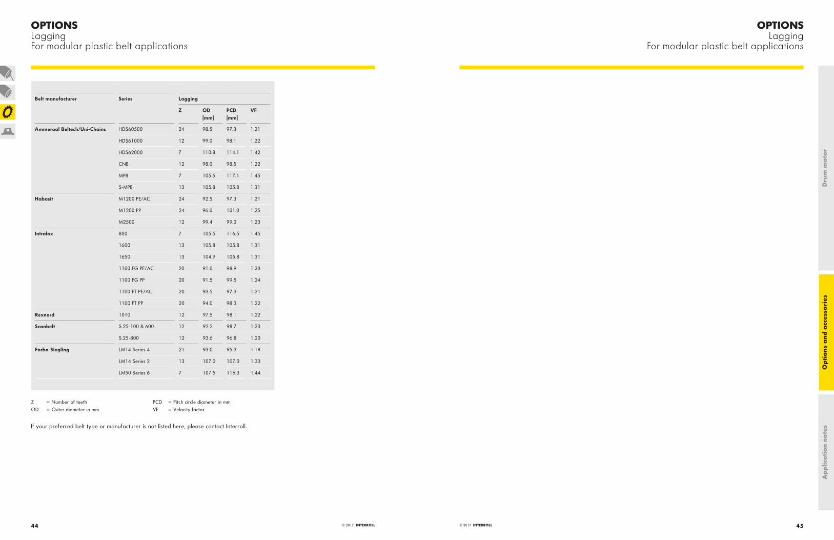
Hygienic, quiet and long lifespan Based on the specifications of the specific belt manufacturer, up to 38 teeth mesh with the profile of the most common modular plastic belts. The lagging made of hot-vulcanized NBR is suitable for applications in food processing with high hygienic requirements: Easy to clean and extremely resistant to oil, grease and chemicals. Furthermore, it ensures smooth running and provides a long lifespan of the belt due to its low abrasion.
Note: It is important to incorporate a calculation of belt pull and speed that is adjusted to the greater outer diameter of the drum motor. Please refer to the velocity factor (VF) in the table page 44.
Technical data
Material Hot vulcanized NBR
Temperature range -40 to 248 °F
Shore hardness 70 ± 5 Shore A
Colors White/blue
Approvals FDA / EC 1935/2004
Versions
PCD
OD
PCD
OD
OD = Outer diameter in mm PCD = Pitch circle diameter in mm
Ap
plic
ati
on
note
sO
pti
ons
and
acc
esso
ries
Dru
m m
oto
r
OPTIONSLagging
For modular plastic belt applications
OPTIONSLaggingFor modular plastic belt applications
45© 2017 INTERROLL© 2017 INTERROLL44
Belt manufacturer Series Lagging
Z OD [mm]
PCD [mm]
VF
Ammeraal Beltech/Uni-Chains HDS60500 24 98.5 97.3 1.21
HDS61000 12 99.0 98.1 1.22
HDS62000 7 110.8 114.1 1.42
CNB 12 98.0 98.5 1.22
MPB 7 105.5 117.1 1.45
S-MPB 13 105.8 105.8 1.31
Habasit M1200 PE/AC 24 92.5 97.3 1.21
M1200 PP 24 96.0 101.0 1.25
M2500 12 99.4 99.0 1.23
Intralox 800 7 105.5 116.5 1.45
1600 13 105.8 105.8 1.31
1650 13 104.9 105.8 1.31
1100 FG PE/AC 20 91.0 98.9 1.23
1100 FG PP 20 91.5 99.5 1.24
1100 FT PE/AC 20 93.5 97.3 1.21
1100 FT PP 20 94.0 98.3 1.22
Rexnord 1010 12 97.5 98.1 1.22
Scanbelt S.25-100 & 600 12 92.2 98.7 1.23
S.25-800 12 93.6 96.8 1.20
Forbo-Siegling LM14 Series 4 21 93.0 95.3 1.18
LM14 Series 2 13 107.0 107.0 1.33
LM50 Series 6 7 107.5 116.3 1.44
Z = Number of teeth PCD = Pitch circle diameter in mmOD = Outer diameter in mm VF = Velocity factor
If your preferred belt type or manufacturer is not listed here, please contact Interroll.
Ap
plic
ati
on
note
sO
pti
ons
and
acc
esso
ries
Dru
m m
oto
r

OPTIONSLagging
For positive drive solid homogeneous belts
OPTIONSLaggingFor positive drive solid homogeneous belts
47© 2017 INTERROLL46 © 2017 INTERROLL
Hygienic and quiet The lagging made of Interroll Premium Hygienic PU is suitable for applications in food processing with high hygienic requirements: Easy to clean and extremely resistant to oil, grease and chemicals. Furthermore, it ensures smooth running and provides a long lifespan of the belt due to its low abrasion. This lagging is available for the most common positive drive solid homogeneous belts as well as for motors in applications with positive drive belts.
Note: It is important to incorporate a calculation of belt pull and speed that is adjusted to the greater outer diameter of the drum motor. Please refer to the velocity factor (VF) in the table page 47.
Technical data
Material Interroll Premium Hygienic PU
Temperature range -40 to 176 °F
Shore hardness 82 ± 5 Shore D
Versions
PCD
ODPCD
OD
Z = Number of teeth PCD = Pitch circle diameter in mmOD = Outer diameter in mm VF = Velocity factor
Belt manufacturer Series Lagging
Z OD[mm]
PCD[mm]
VF
Intralox ThermoDrive 8026 13 104.4 OD + BT 1.32
Volta SuperDrive FHB/FHW-3-SD 9 113.4 OD + BT 1.43
Note: Lace versions cannot be driven with our PU laggings.
If your preferred belt type or manufacturer is not listed here, please contact Interroll.
Ap
plic
ati
on
note
sO
pti
ons
and
acc
esso
ries
Dru
m m
oto
r

OPTIONSSprockets
For modular plastic belt applications
OPTIONSSprocketsFor modular plastic belt applications
49© 2017 INTERROLL48 © 2017 INTERROLL
Precise and wear resistant Stainless steel sprockets are suitable for driving most common modular plastic belts. They are available for motors in applications with positive drive belts or no belt as well as for drum motors with cylindrical shell and key. The hygienic material is naturally qualified for applications in food processing. The sprockets are cut with the help of lasers and are perfectly fit to size.
Note: It is important to incorporate a calculation of belt pull and speed that is adjusted to the greater outer diameter of the drum motor. Please refer to the velocity factor (VF) in the table page 50. Fixed sprockets are available on request. Only one fixed sprocket per drum motor should be fitted to allow for belt expansion.
Technical data
Material Stainless steel
Versions
To use sprockets, drum motors have to be ordered with cylindrical shell and key.
PCD
OD
PCDOD
OD
PCD
OD
PCD
OD = Outer diameter in mm PCD = Pitch circle diameter in mm
Ap
plic
ati
on
note
sO
pti
ons
and
acc
esso
ries
Dru
m m
oto
r

OPTIONSBackstops and balancing
OPTIONSSprocketsFor modular plastic belt applications
51© 2017 INTERROLL© 2017 INTERROLL50
Belt manufacturer Series Rev. Sprocket
Z OD [mm] PCD [mm] VF B [mm]
Intralox 800 l 8 124.2 132.0 1.64 6
900 l 12 107.0 105.0 1.30 3
1000 l 22 112.0 107.0 1.33 4
1100 l 24 118.5 116.0 1.44 18
24 118.5 116.0 1.44 6
1400 l
1500 l 28 118.8 113.0 1.40 6
1600 l 14 111.8 114.0 1.42 8
2400 l 14 114.2 113.8 1.41 12
14 114.2 113.8 1.41 6
Habasit M11XX l 26 111.9 107.1 1.33 8
M12XX l 25 103.7 101.0 1.25 3
M25XX l 15 123.9 122.7 1.52 12
15 123.9 122.7 1.52 12
Rexnord 1010 − 16 131.5 130.0 1.61 8
Scanbelt S.12-400 l 28 117.9 112.0 1.39 4
S.25-100 − 14 113.1 112.0 1.39 4
S.25-400 l 13 105.0 104.0 1.29 4
Forbo-Siegling CM 25 l 13 108.1 110.0 1.37 3
Ammeraal Beltech/Uni-Chains SNB l 13 107.8 106.0 1.32 3
Light l 17 105.0 104.0 1.29 4
Light EP l 9 110.6 111.0 1.38 8
M-SNB & M-QNB l 24 99.5 97.0 1.20 5
QNB l 15 121.50 122.0 1.52 6
SNB M2 l 14 119.2 114.0 1.42 3
Z = Number of teeth VF = Velocity factorOD = Outer diameter in mm B = Sprocket width in mmPCD = Pitch diameter in mm Rev. = Reversible sprocket
Backstops
Backstops prevent a run-back of the belt and load when the power supply is off. Since such a stop is installed directly at the rotor shaft and operates mechanically, no electrical connection is required: The bearing runs only in one direction. This principle achieves a higher holding torque than does an electromagnetic brake.
Note: Backstops are available only for asynchronous drum motors.
Rotational direction looking from the connector side: Available for clockwise (standard) or counterclockwise direction.
Balancing
In principle, static or dynamic balancing can be applied - depending on requirement or motor type. The goal in each case is to reduce vibrations and out-of-balance running for sensitive high speed or dynamic weighing applications. Static balancing is applied to the drum motor shell only; therefore the result must be tested for each application. Dynamic balancing, on the other hand, includes the drum motor rotor, shell and end housings, thus meeting a balancing grade of G2.5.
Any external modification, such as fixtures, laggings or sprockets, has an impact on the imbalance.
Technical data for dynamic balancing
End housing Stainless steel
Rubber lagging material Only hot vulcanized NBR and PU may be used
Max. balancing length FW ≤ 800 mm
Ap
plic
ati
on
note
sO
pti
ons
and
acc
esso
ries
Dru
m m
oto
r

OPTIONSElectromagnetic brakes
OPTIONSElectromagnetic brakes
53© 2017 INTERROLL© 2017 INTERROLL52
Electromagnetic brakes
To safely hold loads on reversible inclined and declined conveyors, electromagnetic brakes are used. They operate via rectifiers. The braking force is applied directly to the rotor shaft of the drum motor. When power to the motor is disrupted, the brake will close automatically. Special advantage: Electromagnetic brakes are quiet and operate with low wear.
Note: Electromagnetic brakes are available only for asynchronous drum motors.
Technical data
Drum motor Rated torque M[Nm]
Rated power[W]
Rated voltage[V DC]
Rated current[A]
DC switching t1[ms]
AC switching t1[ms]
Opening delay time t2[ms]
DM 0080 0.7 12 24 0.5 13 80 20
0.7 12 104 0.12 13 80 20
Response time
The brake opening and closing response time can vary substantially depending on the following:
· Oil type and viscosity· Oil quantity in the drum motor· Ambient temperature· Internal operating temperature of the motor· Switching at input (AC switching) or at output (DC switching)
The difference between AC switching and DC switching is shown in the following table:
AC switching DC switching
Closing response time Slow Fast
Brake voltage approx. 1 V approx. 500 V
Note: For DC switching, the switching contacts must be protected against damage from high voltage.
t 1 t 2
M
t
Fig.: Closing and opening response time
t1 = Closing response timet2 = Opening response time
Reduction of braking torque
The rated braking torque is heavily influenced by the operating conditions inside the drum motor (operation in oil at high temperatures) and the ambient temperature. To calculate the holding torque limit on the drum shell, you need to multiply the rated torque of the brake by the gear ratio of the drum motor. For safety reasons, the calculated brake torque has to be at least 25 % higher than the needed load torque.
Ap
plic
ati
on
note
sO
pti
ons
and
acc
esso
ries
Dru
m m
oto
r

OPTIONSRectifiers
OPTIONSRectifiers
55© 2017 INTERROLL© 2017 INTERROLL54
Rectifiers
Electromagnetic brakes on drum motors are operated via rectifiers. Different versions are available depending on the applications: Half-wave and bridge rectifiers for standard applications as well as fast acting and multiswitch rectifiers for applications in which short opening delay times are necessary.
Note: Rectifiers, just like electromagnetic brakes, are available only for asynchronous drum motors.
Every rectifier is an external component that must be covered or installed in a control box as close to the brake as possible.
Technical data
Input voltage[V AC]
Brake voltage[V DC]
Starting voltage[V DC]
Holding voltage[V DC]
Version Application Article number
115 104 104 52 Fast-acting rectifier A or B 61 011 343
230 207 207 104 Fast-acting rectifier A or B 61 011 343
230 104 104 104 Half wave/bridge rectifier A or B 1 001 440
230 104 190 52 Phase rectifier A 1 001 442
400 104 180 104 Multiswitch rectifier A 1 003 326
460 104 180 104 Multiswitch rectifier A 1 003 326
460 207 207 207 Half wave/bridge rectifier A or B 1 001 441
A = Continuous operationB = Frequent starts/stops
Using a fast acting rectifier or a phase rectifier will save energy because the holding voltage is lower than the starting voltage.
Shielded cables should be used to protect against EMC.
Dimensions
Half wave/bridge rectifier
19
C
E
BD
A
Article number A[mm]
B[mm]
C[mm]
D[mm]
E[mm]
1001440 34 30 25 3.5 4.5
1001441 64 30 54 4.5 5
Phase rectifier
1 2 3 4 5 6
549
9
30
5
4,5
1 2 3 4 65
48,6
4,554
5,6
15
64 17,5
Ap
plic
ati
on
note
sO
pti
ons
and
acc
esso
ries
Dru
m m
oto
r

OPTIONSRectifiers
OPTIONSRectifiers
57© 2017 INTERROLL© 2017 INTERROLL56
Fast-acting rectifier
64
48,6
8 7 6 5 4 3 2 1
15
54
5,6
Ø
8 7 6 5 4 3 2 130
5
4,5
4,5
549
9
17,5
Multiswitch rectifier
ON
1 2 3 4
17,5
54
55,6
9
3073
,6
15
64
69
Ø4,5
544,5
Connection diagram
Interroll recommends installing a switch between (3) and (4) for fast brake release.
1 2 3 4 5 6
input bridge brake
Fig.: Half-wave rectifier
1 2 3 4 5 6
input bridge brake
Fig.: Bridge rectifier
1 2 3 4 5 6
ekarb tupni
Fig.: Phase rectifier
input bridge brake justage delay time
1 2 3 4 5 6 7 8
Fig.: Fast-acting rectifier
VAC VAC
M
1 2 3 4 5 6
Fig.: Multiswitch rectifier
Ap
plic
ati
on
note
sO
pti
ons
and
acc
esso
ries
Dru
m m
oto
r

OPTIONSFeedback devices
OPTIONSFeedback devices
59© 2017 INTERROLL© 2017 INTERROLL58
Feedback devices
If speed, direction and position of the belt or load are to be permanently monitored and controlled, the use of an encoder is recommended. It enables a system control with closed control loop by transmitting low- to high-resolution signals to an external control unit. An encoder is installed onto the rotor shaft or embedded in the rotor bearing and cannot be used simultaneously with a brake or a backstop. Incremental and absolute value encoders are available as encoder types.
All resolutions and speeds provided in the following table refer to the rotor shaft. The drum motor gear ratio must be considered to find the values related to the drum shell.
Encoder types Asynchronous drum motors
Synchronous drum motors
SKF 32 incremental encoder 32 pulses l
RLS incremental encoder 64 to 1024 pulses l l
LTN resolver 2-pole resolver l l
Technical data
SKF 32 incremental encoder
Power supply Vdd = 5 − 24 V
Current consumption Max. 20 mA
Electrical interface Open collector NPN
Output increments A, B
Increments resolution 32 pulses/revolution
Max. cable length 10 m
Note: Interroll recommends the use of an optocoupler for the following reasons:
· To protect the encoder· To enable connection to other levels such as PNP· To get the maximum potential between high and low signal
RLS incremental encoder
Power supply Vdd = 5 V ± 5 %
Current consumption 35 mA
Electrical interface RS422
Output increments A, B, Z, /A, /B, /Z
Increments resolution 64; 512; 1024 pulses/revolution2048 pulses/revolution (max. rotor speed 2500 1/min)
Max. cable length 5 m
LTN resolver
Power supply 7 V
Input frequency range 5 kHz / 10 kHz
Input current 58 mA / 36 mA
Number of poles 2
Transformation ratio 0.5 ± 10 %
Max. cable length 10 m
Ap
plic
ati
on
note
sO
pti
ons
and
acc
esso
ries
Dru
m m
oto
r

OPTIONSFeedback devices
OPTIONSFeedback devices
61© 2017 INTERROLL© 2017 INTERROLL60
Connection diagrams
Abbreviationsye/gn = yellow/green pk = pinkwh = white rd = redbn = brown bu = bluegn = green TC = Thermal controller (WSK)ye = yellow BR = Electromagnetic brakes() = other color NC = Not connectedgy = gray
SKF 32 incremental encoder
wh
SKFEncoder
gn bn ye
VCC/V R/ohm
5 270
9 470
12 680
24 1470
+ 5 - 24V VCC
0V GND
R
A
B
R70
RLS incremental encoder
RLSEncoder
wh gnbn ye gy rdpk bu
+ 5V VCC
0V GND
A
B
RC
RC
/A
/B
Z
/Z
The terminationcan reduce noise
RC
10nF
120
R
71
LTN resolver
wh gnbn ye gypk
Ref+
Ref-
Sin+
Sin-
Cos+
Cos-
E(Ref+,Ref-)E(Ref+,Ref-) =
E(Sin+,Sin-)E(Sin+,Sin-) =
E(Cos+,Cos-)
E(Cos+,Cos-) =
Tr = transformations ratio
Tr x E(Ref+,Ref-) x cosφ
Tr x E(Ref+,Ref-) x sinφ
E0 x sin(ωt)
Resolver
72
Cable
Cable for incremental encoderSKF 32
Cable for incremental encoderRLS
Cable for resolverLTN
Main cores (number) 4 8 6
Cross section 0.14 mm2 0.14 mm2 0.14 mm2
Numeric code and color code color code color code color code
Insulation conductors (main cores) PVC PVC PVC
Insulation conductors (data cores) PVC PVC PVC
Halogen-free No Yes No
Color of outer sheath Gray Gray Gray
Shielded Copper Copper Copper
Outside diameter 4.3 ± 0.3 mm 5.0 ± 0.2 mm 5.8 ± 0.3 mm
Operating voltage max. 250 V 524 V 350 V
Temperature range -20 to +105 °C according to UL -20 to +105 °C according to UL -20 to +80 °C according to UL
Ap
plic
ati
on
note
sO
pti
ons
and
acc
esso
ries
Dru
m m
oto
r

ACCESSORIESMounting brackets
For drum motors and idler pulleys
ACCESSORIESMounting bracketsFor drum motors and idler pulleys
63© 2017 INTERROLL© 2017 INTERROLL62
Mounting overview
Brackets must be mounted in the following way:
B
C
B
A
Dimensions
FJ
L
2,5
HC
B
DI
GK
E
2,5
M
A
Fig.: Right bracket (A) aluminum or VA
GK
E
2,5
BM
HC A
DI
J
L
F2,
52
Fig.: Right bracket (A) PE
Drum motor/deflection roller A[mm]
B[mm]
C[mm]
D[mm]
E[mm]
F[mm]
G[mm]
H[mm]
I[mm]
J[mm]
K[mm]
L M[mm]
DM 0080 13.5 120 85 25 62.5 20 50 40 47.5 9 15 M8 10
20 120 85 25 62.5 20 50 40 47.5 9 15 M8 10
25 120 85 25 62.5 20 50 40 47.5 9 15 M8 10
Mounting brackets
In order to securely fasten Interroll Drum Motors, the corresponding idler pulleys or motors with cable connectors or terminal boxes, suitable brackets made of stainless steel, aluminum and PE are available. It is important that the drum motors feature a continuous threaded hole in the front shaft and idler pulleys a corresponding drilled hole in both shaft ends.
For the dimensions of shafts with threaded holes, refer to the dimensional drawings for the corresponding drum motor.
Product selection
Drum motor Idler pulley Bracket set Material Electrical connector Article number
WAF 13.5 mm WAF 20 mm WAF 25 mm
DM 0080 A + B Aluminum Elbow connectorStraight connector
61008694 61113879 61113880
DM 0080 B + C Aluminum 61008696 61113885 61113886
DM 0080 A + B PE Elbow connectorStraight connector
61008693 61113889 61113890
DM 0080 B + C PE 61008695 61113895 61113896
DM 0080 A + B VA Elbow connectorStraight connector
61113943 61113944 61113945
DM 0080 B + C VA 61113946 61113947 61113948
WAF = Width across flats Ap
plic
ati
on
note
sO
pti
ons
and
acc
esso
ries
Dru
m m
oto
r

ACCESSORIESMounting brackets
For drum motors and idler pulleys
ACCESSORIESMounting bracketsFor drum motors and idler pulleys
65© 2017 INTERROLL© 2017 INTERROLL64
GK
E
2,5
AH
C
F
BM
J
D
L
N
2,5
Fig.: Left bracket (B) aluminum or VA
2,5
BM
AH
C
F J
2,5
2 L
DN
I
GK
EFig.: Left bracket (B) PE
FJ
L
2,5
AH
C
B
DN
GK
E
2,5
M
Fig.: Right bracket (C) aluminum or VA
DIN
FJ
L
2,5
AHC
BM
GK
E
2,5
Fig.: Right bracket (C) PE
Drum motor/idler pulley
Material A[mm]
B[mm]
C[mm]
D[mm]
E[mm]
F[mm]
G[mm]
H[mm]
I[mm]
J[mm]
K[mm]
L M[mm]
N[mm]
DM 0080 Aluminum 13.5 120 85 25 62.5 20 50 40 − 13 15 M8 10 10
20 120 85 25 62.5 20 50 40 − 13 15 M8 10 10
25 120 85 25 62.5 20 50 40 − 13 15 M8 10 10
PE 13.5 120 85 25 62.5 20 50 40 42.5 13 15 M8 10 12.5
20 120 85 25 62.5 20 50 40 42.5 13 15 M8 10 12.5
25 120 85 25 62.5 20 50 40 42.5 13 15 M8 10 12.5
VA 13.5 120 85 25 62.5 20 50 40 − 13 15 M8 10 10
20 120 85 25 62.5 20 50 40 − 13 15 M8 10 10
25 120 85 25 62.5 20 50 40 − 13 15 M8 10 10
Ap
plic
ati
on
note
sO
pti
ons
and
acc
esso
ries
Dru
m m
oto
r

ACCESSORIESPlummer Block
For drum motors and idler pulleys
ACCESSORIESPlummer BlockFor drum motors and idler pulleys
67© 2017 INTERROLL© 2017 INTERROLL66
Plummer Block
The plummer block bracket supports a simple assembly of the drum motors and idler pulleys.
Product selection
Drum motor Material Article number
WAF 13.5 mm WAF 20 mm WAF 25
DM 0080 Aluminum 61008580 61113900 61010381
DM 0080 VA 61113949 61113950 61113951
WAF = Width across flats
Dimensions
GI
K
HM
AB
LL
O
D
E
F
C J
N
Drum motor/idler pulley
A[mm]
B[mm]
C[mm]
D[mm]
E[mm]
F[mm]
G[mm]
H[mm]
I[mm]
J[mm]
K[mm]
L[mm]
M[mm]
N[mm]
O[mm]
DM 0080 13.5 100 10 12 35 47.5 16.5 35 4 6.5 72.5 7.5 M6 − −
20 150 15 20 51 68.5 24.5 70 5 8.5 108 12 M6 3 91
25 150 15 20 51 71 29.5 70 5 8.5 108 12 M6 3 91
Ap
plic
ati
on
note
sO
pti
ons
and
acc
esso
ries
Dru
m m
oto
r

ACCESSORIESIdler pulley with integrated bearings
ACCESSORIESIdler pulley with integrated bearings
69© 2017 INTERROLL68 © 2017 INTERROLL
Interroll deflection rollers can be used on the driven side of conveyor belts. The deflection roller with integrated bearings has a fixed shaft and the same dimensions as a drum motor.
Technical data
Protection rate IP69k
Max. belt tension See equivalent drum motor
Max. belt speed See equivalent drum motor
Shell length See equivalent drum motor
Internal shaft sealing system
NBR
External shaft sealing system
PTFE
Design versions
For idler pulleys you can choose the following design versions:
Component Option Material
Aluminum Mild steel Stainless steel PTFE
Shell Crowned l l
Cylindrical l l
Cylindrical + key for sprockets
l l
End housing l l
Shaft l l
External seal PTFE l
Versions
· Laggings for friction drive belts, page 38· Laggings for modular plastic belts, page 42· Laggings for positive drive solid homogeneous belts, page 46· Sprockets for modular plastic belts (cylindrical shell with key), page 48
Ap
plic
ati
on
note
sO
pti
ons
and
acc
esso
ries
Dru
m m
oto
r

ACCESSORIESIdler pulley with integrated bearings
71© 2017 INTERROLL© 2017 INTERROLL70
Dimensions
AGL
ELC C
HH
D
A-A
F A
A
øB øA
SL=FW-2xP
FW
P P
Type A[mm]
B[mm]
C[mm]
D[mm]
F[mm]
H[mm]
P[mm]
SL[mm]
EL[mm]
AGL[mm]
DM 0080 crowned 81.5 80.5 12.5 30 25 6 3.5 FW - 7 FW + 5 FW + 30
DM 0080 crowned 81.5 80.5 12.5 25* 20 6 3.5 FW - 7 FW + 5 FW + 30
DM 0080 crowned 81.5 80.5 12.5 17* 13.5 6 3.5 FW - 7 FW + 5 FW + 30
DM 0080 cylindrical 81 81 12.5 30 25 6 3.5 FW - 7 FW + 5 FW + 30
DM 0080 cylindrical 81 81 12.5 25* 20 6 3.5 FW - 7 FW + 5 FW + 30
DM 0080 cylindrical 81 81 12.5 17* 13.5 6 3.5 FW - 7 FW + 5 FW + 30
Ap
plic
ati
on
note
sO
pti
ons
and
acc
esso
ries
Dru
m m
oto
r

APPLICATION PRINCIPLESAPPLICATION PRINCIPLES
73© 2017 INTERROLL72 © 2017 INTERROLL
Most of the Interroll Drum Motors are used in unit handling conveyors that are transporting small packages, boxes, cardboard containers, small pallets or other material. Depending on the type of application, friction drive or positive drive belts can be used with asynchronous or with synchronous drum motors.Examples of applications: · Logistics, such as postal sorting and distribution centers · Airport baggage handling · Seafood, meat and poultry · Bakeries · Fruit and vegetables · Beverage and brewing industry · Snacks · Weighing equipment for packages
Friction drive belts
Friction drive belts are driven via the friction between drum motor and conveyor belt. The drum motor is normally crowned to prevent belt wander. The belt must be tensioned in order to transfer the torque from the drum motor. The top surface of the belt can be flat, plain or have a ribbed, grooved or diamond pattern.
Lagging
Interroll offers a broad spectrum of hot and cold-vulcanized laggings made of different materials to increase the friction between belt and drum shell. For more information, page 38.
Positive drive belts
Modular plastic belts, solid homogeneous belts, steel mesh or wire belts are positively driven, i.e., with no belt tension. Since the belt has hardly any direct contact with the drum shell, the heat dissipation is less effective in these applications. For this reason, the drum motor should be used with a frequency inverter that is optimized for this application.
Positive drive belts use less power than friction drive belts, allowing longer conveyors. Because these belts are not tensioned, there is less stress on the bearings and internal parts of the drum motor resulting in a longer service life. A power reduction of 17 % is required for asynchronous motors in these applications.
Interroll recommends the use of profiled lagging wherever possible to ensure easy cleaning, evenly distributed torque transmission and torque dampening at start-up. Stainless steel sprockets can be supplied for belts where profiled lagging is not suitable.
Interroll offers a wide range of profiled lagging according to the belt manufacturers’ specifications. For more information, page 46.
Ap
plic
ati
on
note
sO
pti
ons
and
acc
esso
ries
Dru
m m
oto
r

APPLICATION PRINCIPLES
75© 2017 INTERROLL74 © 2017 INTERROLL
Non-belt applications
For applications without a conveyor belt or with a narrow belt covering less than 70 % of the drum motor face width, heat from the motor can no longer be dissipated via the belt contact. For these applications, we recommend using a 2-pole asynchronous drum motor or synchronous drum motor with frequency inverter.
Examples of non-belt applications include the following:· Pallet roller drive and pallet transfer· V-belt drive for driving roller conveyors· Chain conveyors· Narrow belts covering less than 70 % of the shell width
A power reduction of 17 % is required for asynchronous motors in these applications.
For some non-belt applications the drum motor can be mounted in a non-horizontal position. For more information, page 100.
Ap
plic
ati
on
note
sO
pti
ons
and
acc
esso
ries
Dru
m m
oto
r

AMBIENT CONDITIONSAMBIENT CONDITIONS
77© 2017 INTERROLL76 © 2017 INTERROLL
Hygienic conditions
For food processing and other applications where hygiene is paramount we recommend the following materials, connectors and accessories:
· Stainless steel shell· Stainless steel cover· Stainless steel shafts· External shaft seals made of PTFE· Food grade synthetic oil· NBR hot-vulcanized (FDA & EC 1935/2004)· Molded PU, Shore hardness 82D (FDA & EC 1935/2004 only)· A lagging of hot vulcanized NBR or molded PU should be combined only with a stainless steel shell.· Diamond patterned lagging is not suitable for food processing applications.
Cable connectors/terminal boxes and cables
All cable connectors, terminal boxes and cables are not included in our (EC) 1935/2004 and FDA declaration. These components are considered "Not in direct contact with food stuffs" as described in the following regulations: Commission regulation (EC) No. 2023/2006 of December 22, 2006 on good manufacturing practice for materials and articles intended to come into contact with food. Article 3, definition (d): "Non-food-contact side" means the surface of the material or article that is not directly in contact with food.
FDA Food Code 2009: Chapter 1 - Purpose and Definitions - “Food-contact surface“ means
· (1) A surface of equipment or a utensil with which food normally comes into contact; or· (2) A surface of equipment or a utensil from which food may drain, drip, or splash:
– (a) Into a food, or– (b) onto a surface normally in contact with food.
NSF: On request USDA & 3A: no compliance For food processing applications, Interroll recommends using cable connectors and terminal boxes in stainless steel or Technopolymer.
Hygienic design
All Interroll Drum Motors are designed in accordance with EU Directives for Hygienic Design:
· Machinery Directive (Directive 98/37/EC) Food Machinery section, Appendix 1, point 2.1 (to be replaced by 2006/42/EC)· Document 13 EHEDG-Guideline to the hygienic design of apparatus for open processes, prepared in collaboration with 3-A and
NSF International
EHEDG-compliant drum motors
Interroll Drum Motors configured with components listed below comply with EHEDG, Class I “Open Equipment”. They are ideally suited for ultra-hygienic environments and tolerate high water pressure washing (IP69k):
· Stainless steel shell: cylindrical or crowned· Stainless steel cover· Stainless steel shafts· Shaft seals made of PTFE· Food grade synthetic oil
Conveyor frame
EHEDG design rules recommend the use of rust-free open conveyor frames to facilitate easy cleaning, wash down and disinfection of the conveyor, drum motor and belt. The drum motor should be mounted in the conveyor frame in such a way that there is no metal-on-metal contact between motor shaft and frame support, .e.g. by using a rubber seal between shaft and frame support. The sealing material shall be FDA and EC 1935/2004 compliant.
Cleaning materials
Cleaning specialist Ecolab has certified a 5-year minimum lifetime of materials used by Interroll when exposed to typical cleaning and disinfecting procedures using Ecolab‘s Topax range of products: P3-topax 19, P3-topax 686, P3-topax 56 and P3-topactive DES.
Ap
plic
ati
on
note
sO
pti
ons
and
acc
esso
ries
Dru
m m
oto
r

AMBIENT CONDITIONSAMBIENT CONDITIONS
79© 2017 INTERROLL78 © 2017 INTERROLL
High pressure cleaning
Max. 80 °C / 80 bar for PTFE sealing with IP69k
Note: Changes in ambient temperature and humidity can cause condensation and lead to water inside the terminal box (especially in stainless steel terminal boxes). For example, this can occur when the motor is operated below 5 °C and then cleaned with hot water or steam. Interroll recommends using the cable option in such cases.
High temperatures
Interroll Drum Motors are generally cooled by dissipating heat through the contact between the surface of the drum shell and the conveyor belt. It is essential that each drum motor has an adequate thermal gradient between the internal motor and its ambient operating temperatures.
All drum motors in the catalog are designed and tested in accordance with EN 60034 (without lagging and with a belt) for use at a maximum ambient temperature of +40 °C. Any material can be used, but stainless steel has less heat dissipation.
Laggings can cause thermal overload for positive driven belts. For this reason, use motors with frequency inverters that ensure an optimum temperature. As an alternative, it is also possible to use synchronous motors. Rubber lagging for friction drive belts can also cause thermal overload. External cooling systems can also be used to prevent thermal overload.
If you need a motor for applications with ambient temperatures above +40 °C, please contact Interroll.
Low temperatures
When a drum motor is operated in low temperatures (below +2 °C), consider the viscosity of the oil and temperature of the motor while it is not running. For additional information and notes, please contact Interroll.
Anti-condensation heating for asynchronous drum motors
In ambient temperatures below +1 °C, the motor windings should be heated to regulate the oil viscosity and to keep seals and internal parts at a constant temperature.
If the motor current is switched off for some time and the ambient temperature is very low, then the motor oil becomes viscous. In these conditions problems may occur when starting the motor and at temperatures of around zero frost crystals can form on the sealing surfaces, causing oil leakage. To prevent these problems use anti-condensation heating.
The heater applies a DC voltage to the motor winding. This causes current to flow either in the two motor phases of a 3-phase motor or the main winding of a 1-phase motor. The amperage depends on the voltage applied and the winding resistance. This current creates a power loss in the winding which heats up the motor to a certain temperature. This temperature is determined by the ambient temperature and the amperage.
Information on the correct voltage is available in the motor version tables. The values listed are average values, which can be increased or decreased depending on the required motor temperature and the ambient temperature. Interroll strongly recommends determining the correct voltage by testing under actual operating conditions.
Only DC voltage may be used to heat the motor. The use of AC voltage can cause the motor to move unexpectedly, leading to serious damage or injury.
The stationary heating system should only be used when the motor is actually idle. The heating voltage must be switched off before the motor is operated. This can be ensured by using simple relays or switches.
The suggested voltages are calculated to prevent the formation of condensation. If the motor needs to be held at a specific temperature, then the stationary heating system must be set up accordingly. In this case, please contact your Interroll customer consultant.
The anti-condensation heating voltage must be connected to any two phases of a 3-phase motor. The heating current supplied by the heating system can be calculated as follows:
IDC =USHdelta
. 3
RMotor . 2
Fig.: Dreieckschaltung
RMotor . 2
USHstarIDC =
Fig.: Sternschaltung
Ap
plic
ati
on
note
sO
pti
ons
and
acc
esso
ries
Dru
m m
oto
r

AMBIENT CONDITIONSAMBIENT CONDITIONS
81© 2017 INTERROLL80 © 2017 INTERROLL
Low noise
All Interroll Drum Motors excel with relatively low noise development and vibrations. The performance levels are not specified or guaranteed in this catalog because they can vary depending on the type of motor, number of poles, speed and application. For specific low-noise applications, please contact your Interroll customer consultant.
Altitudes above 1000 m
Operating a drum motor at an altitude of more than 1000 m may result in power loss and thermal overload due to the low atmospheric pressure. This must be considered when calculating your power requirement. For more information, please contact your Interroll customer consultant.
Supply voltage (asynchronous drum motors only)
Using 3-phase 50 Hz motors in a 60 Hz supply system with the same voltage
· Motor rated: 230/400 V – 3 ph – 50 Hz· Supply voltage: 230/400 V – 3 ph – 60 Hz
Using a 3-phase 50 Hz motor in a 60 Hz supply system will increase the frequency, and therefore the speed, by 20 %. If the other rated motor parameters are to be kept constant, a 20 % higher input voltage is required (U/f law). However, if this 20 % higher voltage is not supplied, all voltage-dependent parameters will be affected in accordance with the following table:
System voltage = rated motor voltage
Motor data
Power P kW 100 %
Rated speed nn 1/min 120 %
Rated torque Mn Nm 83.3 %
Starting torque MA Nm 64 %
Pull-up torque MS Nm 64 %
Pull-out torque MK Nm 64 %
Rated current IN A 96 %
Starting current IA A 80 %
Power factor cos φ 106 %
Efficiency ƞ 99.5 %
Supply voltage Motor rating
230/400 V 230/400 V
3 ph 3 ph
60 Hz 50 Hz
Ap
plic
ati
on
note
sO
pti
ons
and
acc
esso
ries
Dru
m m
oto
r

AMBIENT CONDITIONS
83© 2017 INTERROLL82 © 2017 INTERROLL
Using 3-phase 50 Hz motors in a 60 Hz supply system with 15/20 % higher voltage
· Motor rated: 230/400 V – 3 ph – 50· Supply voltage: 276/480 V - 3 ph - 60 - 2 and 4 poles (motor voltage + 20 %)
Using a 3-phase 50 Hz motor in a 60 Hz supply system with 20 % higher voltage will increase the frequency and therefore the speed by 20 %, but will maintain all the rated motor parameters subject to small variations (U/f law).
Note: If the supply voltage is increased by 15 % compared to the motor voltage, the actual motor output decreases to 92 % of the original motor output.
Supply voltage = 1.2 x rated motor voltage (for motors with 2 and 4 poles)
Motor data
Power P kW 100 %
Rated speed nn 1/min 120 %
Rated torque Mn Nm 100 %
Starting torque MA Nm 100 %
Pull-up torque MS Nm 100 %
Pull-out torque MK Nm 100 %
Rated current IN A 102 %
Starting current IA A 100 %
Power factor cos φ 100 %
Efficiency ƞ 98 %
Supply voltage Motor rated
230/480 V 230/400 V
3 ph 3 ph
60 Hz 50 Hz
Ap
plic
ati
on
note
sO
pti
ons
and
acc
esso
ries
Dru
m m
oto
r

INDUSTRIAL SOLUTIONSINDUSTRIAL SOLUTIONS
85© 2017 INTERROLL84 © 2017 INTERROLL
Interroll offers a wide range of industrial solutions for its drum motors. In this chapter, only the most important solutions will be explained.
General logistics
Conveying in logistics, warehousing and storage sectors covers a wide spectrum of applications in industries, such as electronics, chemicals, food, automotive and general manufacturing. All motors in this catalog are suitable for general logistics applications.
High performance and dynamic conveying
Modern Industry today expects high efficiency and increased productivity as well as fast bus communication between zones and zero maintenance. Interroll provides the perfect drives for high performance applications that typically use smart belts, packaging machines, weighing
machines and sorting equipment. This type of equipment requires high torque, fast acceleration/deceleration, dynamic braking and bus communication. If more control is needed, the motor can be fitted with an encoder to run it as a servo-drive.
Food processing
Interroll Drum Motors are ultra-hygienic and easy to clean. All drum motors for food processing comply with EC 1935-2004 and FDA. NSF-compliant motors are available on request. Interroll is a member of the EHEDG (European Hygienic Engineering Design Group).
Consider the ambient conditions before choosing drum motor versions, options and accessories.
Suitable drum motors· For friction drive belts use an asynchronous drum motor.· For positive drive belts use either a drum motor for applications with positive drive belts or no belts, or an asynchronous drum motor
with frequency inverter.· A synchronous drum motor can also be used for all applications.
Torque transmissionFor moist or wet food applications with friction drive belts Interroll recommends rubber lagging on the drum motor to improve the friction between the belt and drum shell. In continuously wet conditions, longitudinal grooved lagging can be used to dissipate the water flow and improve the grip.
Ap
plic
ati
on
note
sO
pti
ons
and
acc
esso
ries
Dru
m m
oto
r

INDUSTRIAL SOLUTIONS
87INTERROLL86 © 2017 INTERROLL
Options and accessories· Stainless steel or other materials approved for food or hygienic applications.· Drum motors for food processing are supplied with food-grade oil.· Interroll offers a variety of hot-vulcanized lagging materials approved for use in food processing (FDA and EC 1935/2004).· Hot-vulcanized NBR and molded PU lagging has a longer service life, withstands higher torques and is easier to keep clean than
cold-vulcanized lagging.
Conveyor frameEHEDG design rules recommend the use of rust-free open conveyor frames to facilitate easy cleaning, wash down and disinfection of the conveyor, drum motor and belt. The drum motor should be mounted in the conveyor frame in such a way that there is no metal-on-metal contact between motor shaft and frame support, e.g. by using a rubber seal between shaft and frame support. The sealing material shall be FDA and EC 1935/2004 compliant.
Cleaning MaterialsCleaning specialist Ecolab has certified a 5-year minimum lifetime of materials used for Interroll Drum Motors when exposed to typical cleaning and disinfecting procedures using Ecolab‘s Topax range of products: P3-topax 19, P3-topax 686, P3-topax 56 and P3-topactive DES.
Airport logistics
Airport applications, such as conveyors at check-in, X-Ray machines and scanning equipment, require low noise and frequent starts and stops. Most applications use friction drive belts made of PU, PVC or rubber.
Ap
plic
ati
on
note
sO
pti
ons
and
acc
esso
ries
Dru
m m
oto
r

DESIGN GUIDELINESDESIGN GUIDELINES
89© 2017 INTERROLL88 © 2017 INTERROLL
A belt conveyor is designed primarily to transport or transfer materials from one place to another. In its simplest form, a belt conveyor normally consists of a longitudinal frame with a drum motor at one end and an idler pulley at the other end around which a continuous belt revolves. The belt, which carries the materials, can be supported either by rollers or a steel, wood or plastic slider bed. This chapter on design guidelines is subdivided into two sections: friction drive belt conveyors and positive drive belt conveyors, since each type requires a different method of torque transfer.
Friction drive belt conveyors
1 Drum motor2 Slider bed3 Tie-in roller4 Steering idler5 Tensioning roller6 Support roller7 Conveyor belt8 Carrying idler9 Idler pulley
Friction drive belt conveyors, e.g. rubber, PVC or PU flat belts, rely on high friction between the drum motor and belt and sufficient belt tension in order to transmit the torque from the drum motor to the belt. For typical friction factors, refer to the table page 89.
Torque transmission
Normally the steel crowned shell of the drum motor is sufficient to transmit the torque but care must be taken not to over-tension the belt, which could damage the drum motor shaft bearings or even the belt itself.
Belt tension
The conveyor belt should only be tensioned in line with the manufacturer’s recommendations and the tension should only be enough to drive the belt and load without belt slip. Over-tensioning can damage the drum motor and belt. Maximum belt tensions for the drum motors can be found in the product pages of this catalog.
Fig.: Damaged drum motor due to over-tensioning
Lagging
To improve the torque transmitted from the drum motor to the belt, rubber lagging can be applied to the drum shell to produce more grip.
A smooth lagging or a lagging with diamond pattern is well suited for dry applications. It is also possible to use laggings with grooves or other laggings. Longitudinal grooved lagging is advisable to dissipate water in food processing or wet applications. Diamond patterned lagging can be used for non-food wet applications.
When external belt tracking devices are installed, cylindrical shells can be used to prevent opposing influences.
Additional friction factor
Depending on the belt material, the friction between conveyor belt and drum motor can vary.
Consider the following friction factors when calculating the belt tension:
Drum motor surface Conditions Belt material
Frictioned rubber
PVC Polyester fabrics
Impregnation with Ropanol
Steel Dry 0.25 0.35 0.20 0.25
Wet 0.20 0.25 0.15 0.20
Smooth lagging Dry 0.30 0.40 0.25 0.30
Grooved lagging Wet 0.25 0.30 0.20 0.25
Ap
plic
ati
on
note
sO
pti
ons
and
acc
esso
ries
Dru
m m
oto
r

DESIGN GUIDELINESDESIGN GUIDELINES
91© 2017 INTERROLL90 © 2017 INTERROLL
Belt wrap angle
There is another way to improve the torque transmitted from the drum motor to the belt: You can increase the angle of belt wrap around the drum motor. The belt wrap angle is measured in degrees. A larger belt wrap angle gives better traction between the belt and drum motor, and the belt requires less belt tension. A minimum angle of 180° is generally recommended to transfer the full torque to the belt. Increasing the angle to 230° or more is indeed possible to reduce the belt tension and, therefore, the wear of drum motor and belt.
180°
Fig.: Minimum belt wrap angle for friction drive belt conveyors
230°
Fig.: Increased belt wrap angle for friction drive belt conveyors
Roller bed conveyor
Due to their lower friction, roller bed conveyors require less power, less belt tension and are therefore more efficient than slider bed conveyors. Roller bed conveyors are especially suitable for longer conveyors with heavy loads.
Fig.: Roller bed conveyor
Slider bed conveyor
Belt conveyors using a slider bed have more friction and require higher power and belt tension than belt conveyors with rollers and are therefore less efficient. However, the transported goods lie on the belt with greater stability. Due to its simple construction, it is a lower cost option than the roller bed conveyor.
Fig.: Slider bed conveyor
Drive positions
The drum motor is usually positioned at the head or discharge end of the conveyor but can be positioned elsewhere to suit the application or design.
Head driveThe head drive positioning (discharge end) is the most common and preferred option for non-reversible conveyors and is ideal because it is simple to design and easy to install. Furthermore most of the belt tension is on the carrying side and allows the drum motor to transfer its full torque to the belt.
Fig.: Non-reversible conveyor with head drive Fig.: Optional design for non-reversible long conveyor with center take-up
Ap
plic
ati
on
note
sO
pti
ons
and
acc
esso
ries
Dru
m m
oto
r

DESIGN GUIDELINESDESIGN GUIDELINES
93© 2017 INTERROLL92 © 2017 INTERROLL
Tail driveA conveyor's tail end (loading or receiving end) is not the ideal drive position as the drum motor is pushing the carrying side of the belt and more tension is applied to the return side. Therefore, the full torque of the drive may not be applied. This type of drive can lead to belt waves (belt lifting on the top side), jumping and undesirable belt wander. If a tail drive is necessary, it is recommended only for use with short friction drive belt conveyors of 2 to 3 meters in length with light loads. (It is not recommended for positive drive belts.)
Fig.: Short friction drive belt conveyor with tail drive
Center driveA center drive can be used for longer belt conveyors where a large diameter drum motor is required and there is insufficient space available at the head end. The center drive can also be used for reversible conveyors because the belt tension is distributed more evenly between the carrying and return side of the belt. Belt tracking issues for forward and reverse operation can be minimized.
Fig.: Long belt conveyor with center drive Fig.: Center drive for long belt conveyor with increased belt wrap
Reversible driveInterroll Drum Motors are suitable for reversing unless fitted with a backstop. However, the motor control must be designed in such a way that the drum motor is brought to a complete standstill before reversing, otherwise serious damage to the gear box could occur. Drum motors with a backstop may be used only for conveying in one direction. The direction is indicated by an arrow on the end housing.
Positive drive belt conveyors
1 Modular plastic belt2 Idler pulley with sprockets3 Support slats4 Catenary sag5 Support rollers6 Drum motor
Positive drive belt systems have a lower power consumption than friction drive belts, enabling longer conveyor constructions. As there is no belt tension, there is less stress on the drum motor bearings. Since the belt has no direct contact with the drum shell, the heat dissipation is less effective in these applications. For this reason, the drum motor should be used with a frequency inverter that is optimized for this application. Alternatively, motors for applications with positive drive belts or no belts can be used.
Examples of positive driven belts include the following:
· Modular plastic belts· Positive drive solid homogeneous belts· Steel slatted belts· Steel mesh or wire belts· Toothed belt· Chain conveyors
Positive drive belt installations can be quite complex and are not discussed in detail in this catalog. Please refer to the belt supplier’s instructions and contact Interroll if further advice is required.
Ap
plic
ati
on
note
sO
pti
ons
and
acc
esso
ries
Dru
m m
oto
r

DESIGN GUIDELINESDESIGN GUIDELINES
95INTERROLL94 © 2017 INTERROLL
Torque transmission
Drum motors for positive drive belt conveyors are normally supplied with full-width machined rubber lagging that engages the profile of the conveyor belt on the underside. Alternatively, a cylindrical drum shell with a laterally welded key can be supplied enabling any type of steel, stainless steel or plastic sprocket wheels to be fitted to the shell. The number of sprockets depends on the belt width and load but there must be a minimum of three. The calculation of the number of sprockets required can be found in the belt manufacturer’s catalog. Due to the thermal expansion of the belt, all sprockets supplied by Interroll are floating and therefore it may be necessary to guide the belt using side guides built into the conveyor frame in order to achieve a center belt tracking. As an alternative, Interroll can supply a fixed sprocket positioned in the center of the belt.
Fig.: Belt tracking
1 Belt2 Support slats3 Wear strips4 Side supports/side guides
Belt tension
Due to its positive drive, the conveyor belt generally requires no belt tension and uses only the gravity from its own weight to engage the lagging or sprocket profile. On the return side, the belt should hang loose to accommodate the changing length of the belt due to thermal expansion and contraction. The installation and conveyor design should comply with the belt manufacturer’s recommendations.
Fig.: Short conveyor without support rollers on the return belt Fig.: Medium and long conveyor with catenary sag and support rollers on the return belt
Velocity factor
The increased diameter of the drum motor when fitted with lagging or sprockets will affect the rated speed of the motors shown in this catalog. In order to calculate the final belt speed, please use the following calculation. The velocity factor VF can be found in the Options section, page 43.
Vbelt = Vdm x VF
Vbelt = Belt speed VF = Velocity factorVdm = Rated speed of drum motor
The torque is transmitted directly from the drum shell via the lagging or indirectly through the key and sprockets to the belt. This transfers up to 97 % of the mechanical output onto the belt. In start-stop applications, the use of a soft start function or frequency inverter will increase the lifespan of the belt, sprockets and gear box.
Belt pull correction factor
When using lagging or sprockets, the rated belt pull of the drum motor will be reduced. The actual belt pull is calculated as follows:
Corrected belt pull = Rated belt pull/VF
Drive positions
For positive drive belt conveyors either a head drive or center drive is possible.
Head drive
The drum motor should be positioned at the head (discharge end) of the conveyor so that the carrying side of the belt is pulled under tension.
Fig.: Head drive for positive drive belt conveyors
Ap
plic
ati
on
note
sO
pti
ons
and
acc
esso
ries
Dru
m m
oto
r

DESIGN GUIDELINESDESIGN GUIDELINES
97© 2017 INTERROLL96 © 2017 INTERROLL
Tail drive
Tail drives are not recommended. If the drum motor is located at the tail end (loading side) of the conveyor and attempts to push the belt, then the belt tension at the return belt is greater than at the carrying side of the belt. The belt "jumps" over the profile of the lagging or the sprockets and forms buckles in the excessive belt length – a safe transport of the material is no longer ensured.
Center drive
Center drives can be used for long unidirectional conveyors or for reversible conveyors. In the case of reversible conveyors, great care and attention is required for their design. Please contact the belt manufacturer for advice.
Other conveyors
Inclined conveyors
Inclined conveyors require more power and higher belt tension than horizontal conveyors to move the same load. A backstop should be considered for single direction inclined conveyors to prevent rollback of the belt and load.
Fig.: Inclined conveyor
Reversible inclined or declined conveyors
An electromagnetic brake should be considered to prevent accidental reversal and rollback of the belt and load. To reduce acceleration and over-run of the belt and load on a declined conveyor calculate the power required as for an inclined conveyor.
Knife-edge conveyors
Knife edges reduce the gap between the transfer points of two conveyors. However, with friction drive belt conveyors, knife edges can severely increase the belt pull and tension required to overcome the increased friction between belt and knife edge. To reduce this friction the belt transfer angle should be increased as much as possible and a roller with a small diameter should replace the knife edge.
Fig.: Knife-edge conveyor
Food processing conveyors
EHEDG design rules recommend the use of rust-free open conveyor frames to facilitate easy cleaning, wash down and disinfection of the conveyor, drum motor and belt.
Fig.: Open conveyor design for hygienic cleaning
Plough and diverter units
If the drum motor is installed in a plough or diverter unit, it is frequently installed in a vertical position. This requires ordering a special motor design.
Ap
plic
ati
on
note
sO
pti
ons
and
acc
esso
ries
Dru
m m
oto
r

DESIGN GUIDELINESDESIGN GUIDELINES
99© 2017 INTERROLL98 INTERROLL© 2017
Frequent starts/stops
Frequent starts and stops can cause thermal overload of the motor and premature wear of the gear box, reducing the lifespan of the drum motor. In applications such as these, Interroll recommends the use of a frequency inverter to optimize the heat loss of the motor and a soft-start function to reduce the start-up load on the gear box. Synchronous or asynchronous drum motors with a frequency inverter are ideal for these applications.
Control systems
Interroll supplies brakes, backstops, encoders and frequency inverters for its range of drum motors.
What drive control system do you need?
As with any drive system, when you select a drum motor, you also must decide on the type and scope of control you will need to optimize your application. You should therefore select a motor and control system that ensures efficient and trouble-free operation right from the outset. Interroll offers a series of user-friendly drive and control solutions in its standard product range.
Control guide matrix
AC asynchronous motors AC permanent magnet synchronous motors
Direct connection to power supply
Frequency inverter from third parties
Frequency inverter from third parties or servo driver
Frequency inverter or servo driver recommended by Interroll
Direct connection to power supply l
Voltage-controlled frequency
l
Sensorless vector control l l l
Control loop closed l l l
Speed setting
The drum motor and therefore the conveyor belt speed will be influenced by the load, belt tension and rubber lagging thickness. Speeds provided in the product pages are based on rated load and accurate to ±10 %; for more accurate speeds use a frequency inverter/drive control to overcome these influences. For precise speeds use a frequency inverter/drive control combined with an encoder or other feedback device. Frequency inverters can also be used with asynchronous motors to increase the rated speed. However, the available torque will then be reduced starting at a frequency of 50 Hz. Synchronous drum motors with a suitable frequency inverter will offer solutions for most of these issues and can increase performance, throughput and efficiency.
For asynchronous drum motor brakes and backstops, see page 51.
Merges transfers and in-feed control
For asynchronous drum motors use a frequency inverter with DC braking (with or without encoder) to control the merge process. Alternatively, for precise, dynamic control and/or high throughput, use a synchronous drum motor.
Feedback system
Use an integrated encoder or other feedback device for precise speed and positioning data (see page 58).
Operating modes
The following operating modes comply with IEC 60034-1.
Continuous running duty S1
Operation at constant load which is long enough to reach a thermal steady-state condition.
P
t
t
P
t
P = Power inputPW = Electrical lossesϑ = Temperatureϑmax = Max. temperature achievedt = Time
The majority of Interroll Drum Motor windings with an efficiency of over 50 % are suitable for operating mode S1 and continuous running duty. Please refer to the electrical data tables for standard motors and motors for applications with positive drive belts or no belts. The value is listed with the symbol η for efficiency.
Ap
plic
ati
on
note
sO
pti
ons
and
acc
esso
ries
Dru
m m
oto
r
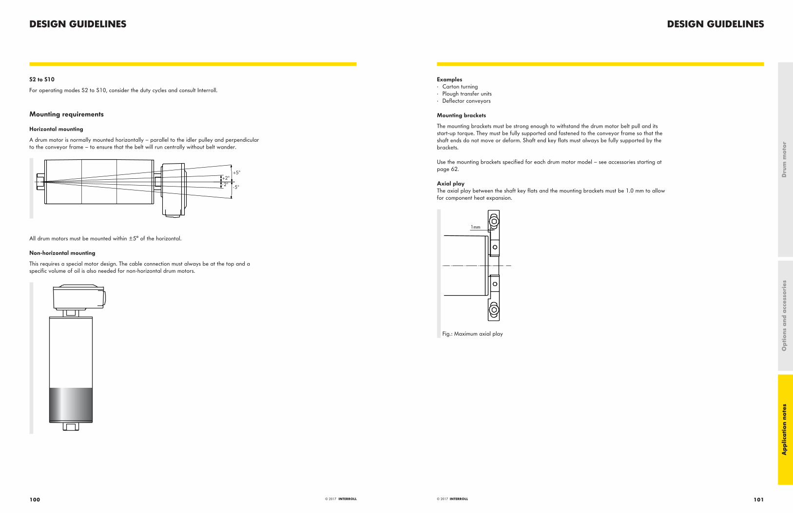
DESIGN GUIDELINESDESIGN GUIDELINES
101© 2017 INTERROLL100 © 2017 INTERROLL
S2 to S10
For operating modes S2 to S10, consider the duty cycles and consult Interroll.
Mounting requirements
Horizontal mounting
A drum motor is normally mounted horizontally – parallel to the idler pulley and perpendicular to the conveyor frame – to ensure that the belt will run centrally without belt wander.
All drum motors must be mounted within ±5° of the horizontal.
Non-horizontal mounting
This requires a special motor design. The cable connection must always be at the top and a specific volume of oil is also needed for non-horizontal drum motors.
Examples· Carton turning· Plough transfer units· Deflector conveyors
Mounting brackets
The mounting brackets must be strong enough to withstand the drum motor belt pull and its start-up torque. They must be fully supported and fastened to the conveyor frame so that the shaft ends do not move or deform. Shaft end key flats must always be fully supported by the brackets.
Use the mounting brackets specified for each drum motor model – see accessories starting at page 62.
Axial playThe axial play between the shaft key flats and the mounting brackets must be 1.0 mm to allow for component heat expansion.
Fig.: Maximum axial play
Ap
plic
ati
on
note
sO
pti
ons
and
acc
esso
ries
Dru
m m
oto
r

DESIGN GUIDELINESDESIGN GUIDELINES
103© 2017 INTERROLL102 © 2017 INTERROLL
Torsion playThe torsion play between the shaft key flats and the mounting brackets must be no more than 0.4 mm.
max. 0,4 mm
Fig.: Maximum torsion play
There must be no clearance between the shaft key flats and mounting bracket if the drum motor is to be used for frequent reversible operations or a large number of starts and stops.
Supported lengthAt least 80 % of the key flats must rest on the mounting bracket.
Other mounting devicesThe drum motor can also be installed directly in the conveyor frame without mounting brackets. In this case, the shafts must rest in recesses in the conveyor frame that have been reinforced accordingly to meet all of the conditions listed above.
Belt adjustment
Drum motors for friction drive belts are normally supplied with crowned shells in order to ensure central belt tracking and prevent misalignment of the belt during operation. However, the belt must be checked and adjusted at its initial start up and maintained as necessary.
Diagonal checkThe conveyor side frames must be parallel to each other and level on both sides ensuring the drum motor fits exactly at 90 degrees square to the frame.
This can be checked using the following procedure:
· The difference in length of the two diagonals must not be more than 0.5 %.· The diagonals are measured from the drum motor shaft to the idler pulley shaft or from belt edge to belt edge.
Fig.: Diagonal check
Belt positionThe underside of the belt should be flush with the conveyor slide or roller bed and must not be more than 3 mm above these.
0-3 mm
Fig.: Maximum distance between belt and conveyor bed
Misaligned drum motors, belts or idler pulleys may cause high friction and overheat the drum motor. This may also result in premature wear of the belt and lagging.
Belt pull
The rated belt pull, power and speed for each drum motor version are shown in this catalog.
F
Ap
plic
ati
on
note
sO
pti
ons
and
acc
esso
ries
Dru
m m
oto
r

DESIGN GUIDELINESDESIGN GUIDELINES
105© 2017 INTERROLL104 © 2017 INTERROLL
You can calculate the belt pull F using the following formulas.
The formulas are only intended as guidelines since they are based on typical operating conditions. The effect of additional friction from the following factors is not taken into account:
· Hoppers· Rubber seals· Cleaning devices, such as ploughs, scrapers and brushes· Friction between the product and side guides
1 Scraper2 Plough3 Hopper4 Brush
Belt pull calculation (F)
F=F0 +F1 +F2+F3+safety factor
Please add a safety factor of 20 % to this calculation.
Conveying system L
Pm1
Roller bed conveyor
L
Pm1
Slider bed conveyor
L
Pm1
Pm2 Double slider bed conveyor
Force without load
F0= 0.04·g·L·(2 Pn+Ppr) F0= g·L·Pn·C2 F0= g·L·Pn(C2+C4)
Force to convey materials horizontally
F1=0.04·g·L·Pm1 F1=g·L·Pm1·C2 F1=g·L·(Pm1·C2+Pm2·C4)
H
Force to convey materials on incline
F2=g·H·Pm1* F2=g·H·Pm1* F2=g·H·(Pm1-Pm2)*
Accumulation
F3=g·L·Pm1·C1 F3=g·L·Pm1·C1 F3=g·L·(Pm1·C1+Pm2·C3)
Pn in kg/m = Belt weight per meterPpr in kg/m = Weight of rotating parts of the belt conveyor (carrying and return section) per meter lengthPm1 in kg/m = Weight of the conveyed product on the carrying section, for each meter of length of the belt conveyorPm2 in kg/m = Weight of the conveyed product on the return section, for each meter of length of the belt conveyorC1 = Coefficient of friction between product and carrying side **C2 = Coefficient of friction between carrying side and slider bed **C3 = Coefficient of friction between return side and product **C4 = Coefficient of friction between return side and slider bed **L in m = Center-to-center lengthH in m = Height difference in conveyorF0 to F3 in N = Belt pull components for operating conditions showng in m/s² = 9.81
* The value F2 is negative with declined conveyors. However, to prevent over-run acceleration due to gravity,F2 should be positively calculated as for inclined conveyors.
** Information about friction factors page 89.
Ap
plic
ati
on
note
sO
pti
ons
and
acc
esso
ries
Dru
m m
oto
r

DESIGN GUIDELINESDESIGN GUIDELINES
107© 2017 INTERROLL106 © 2017 INTERROLL
Coefficient of friction
Belt material Slider bed material C2, C4 Product material C1, C3
PE Steel Steel Glass, Technopolymer
Technopolymer
PE 0.30 0.15 0.13 0.09 0.08
PP 0.15 0.26 0.32 0.19 0.17
POM 0.10 0.20 0.20 0.15 0.15
PVC/PU 0.30 0.30 0.30
Polyamide or polyester
0.18 0.18 0.17
Rubber 0.40 0.40 0.40 0.40
Belt tension
The following must be observed when calculating the belt tension:
· Length and width of conveyor belt· Belt type· Check the belt tension required to transport the load· Check the belt elongation necessary for the installation. Depending on the load, the belt elongation for the assembly should be
between 0.2 – 0.5 % of the belt length.· The values for the belt tension and elongation are available from the belt manufacturer.· Ensure that the required belt tension does not exceed the maximum belt tension (TE) of the drum motor.
T1
T2
T1+T2 =TE
The required belt tension T1 (top side) and T2 (bottom side) can be calculated in accordance with DIN 22101 or the CEMA standard. Based on the information from the belt manufacturer, the actual belt tension can be roughly determined by a measurement of the belt elongation during tensioning.
The maximum allowable belt tension (TE) of each drum motor is specified in the drum motor tables in this catalog. Belt type, belt thickness and drum motor diameter must match the information from the belt manufacturer. If the diameter of the drum motor is too small, damage to the belt can result.
If the belt tension is too strong, it can damage the shaft bearings and/or other internal components of the drum motor and shorten the service life of the product.
Belt elongation
The belt tension is created by the force of the belt when it is stretched in longitudinal direction. To prevent damage to the drum motor, it is absolutely necessary to measure the belt elongation and to determine the static belt tensioning force. The calculated belt tension must be equal to or lower than the values specified in the drum motor tables in this catalog.
Conveyor belt
Idler
With increasing the distance between idler
and drum motor the belt elongates
Drum motor
Fig.: Belt elongation
Measuring the belt elongation
The belt elongation can very easily be determined using a measuring tape. Mark the not-tensioned belt on two points in the belt center, where the outer diameter of the drum motor and idler pulley is the biggest due to the crowning. Measure the distance between the two marks parallel to the belt edge (Be0). The longer the distance between the two marks, the more precise the measurement of elongation will be. Now start to tension the belt and adjust it. Once the belt is adjusted and tensioned measure the distance between the two marks again (Be). The belt elongation increases the distance.
Be
[mm
]
BeO
[mm
]
BW BW
Fig.: Measuring the belt elongation
Ap
plic
ati
on
note
sO
pti
ons
and
acc
esso
ries
Dru
m m
oto
r

DESIGN GUIDELINESDESIGN GUIDELINES
109© 2017 INTERROLL108 © 2017 INTERROLL
Belt elongation calculation
With the belt elongation measurement you can calculate the belt elongation in %.
Be% =Be
.100%
Be0
-100
Fig.: Formula for calculating the belt elongation in %
For the calculation of belt elongation, the following values are needed:
· Belt width in mm (BW)· Static force per mm belt width with 1 % elongation in N/mm (k1 %). This value is usually given in the belt data sheet or can be
requested from the belt supplier.
TE[static] = BW . k1% . Be% . 2
Fig.: Formula for calculating the static belt tensioning force in N
Load and loading method
· Consider the method of loading, such as a feed conveyor, hopper loading or shock loading, and adjust the required belt pull and belt tension accordingly
· Consider the type and length of the load with regard to specific point loads and ensure that the weight of the point load (in Newtons) never exceeds the maximum belt tension (TE) of the drum motor.
Drum motor diameter
· Choose the drum motor with the smallest diameter, but with due consideration of all application parameters and ambient conditions· Check the minimum flexing diameter allowed for the belt and choose the drum motor diameter accordingly
All belts have a safe minimum diameter for normal or back flexing when used with drum motors or idler pulleys. Always refer to the belt manufacturer‘s specification for this information and choose the drum motor diameter accordingly, otherwise serious damage to the belt or drum motor may result. If the drum motor diameter is too small, insufficient torque will be transmitted to the belt and belt slip or "jumping" may occur.
To illustrate: The belt shown below has cross cleats and side frames and requires a larger diameter of drum motor than would be required for a plain flat belt.
Single phase asynchronous motors
Single phase AC motors are typically used when 3-phase voltage is not available.
Principle
Single phase AC motors have a main winding and an auxiliary winding to create a rotating field. The phase shift between the main and auxiliary phase is created by a permanently connected running capacitor.
Starting torque/starting capacitors
The starting torque can be very limited because of the imperfect rotating field:
· The starting torque of a 3-phase AC motor is typically 120 – 410 % of rated torque· The starting torque of a 1-phase AC motor is typically 65 – 115 % of rated torque
Some 1-phase AC motors – especially in the higher power range – need an additional starting capacitor to reach a starting torque of 150 – 200 % of the rated torque. This starting capacitor should be the same size as the running capacitor and has to be switched parallel to it. This should be done ideally via a current-dependent switch relay during the start-up sequence of the motor. When the right torque/current has been reached, the starting capacitor is switched off by the relay. The capacity value of the running capacitor is always stated on the motor type label.
Noise
1-phase motors generally have a higher noise level at zero-load operation compared to 3-phase motors, because of the difference in the rotating field. Typically there is an erratic noise that increases steadily. This does not affect the operation of the drum motor and will normally disappear when belt tension is applied or the drum motor is run under load. Claims cannot be accepted due to this noise effect.
Ap
plic
ati
on
note
sO
pti
ons
and
acc
esso
ries
Dru
m m
oto
r

DESIGN GUIDELINES
111© 2017 INTERROLL110 © 2017 INTERROLL
Capacitors and relays
All capacitors must be ordered separately for single phase drum motors. A suitable current-dependent relay to convert the starting capacitor to a running capacitor can be supplied if needed. For more information, please contact your Interroll customer consultant. The correct installation of the starting capacitor is shown in the wiring diagram supplied with the drum motor.
Interroll strongly recommends the use of 3-phase motors, since they are more efficient and save energy. Improved efficiency can be achieved by using a 3-phase motor with a frequency inverter. If a single phase supply is the only option, consider using a 3-phase motor together with a frequency inverter that converts the single phase input voltage into a 3-phase output voltage.
Standard Interroll capacitors Article number
3 μF 1100692
4 μF 1000477
6 μF 1100821
8 μF 1100724
Note: Capacitors can have different service lives. Use only B rated capacitors.
Final design steps
Before deciding on the final design, additional factors, such as the motor's switching frequency, still must be taken into account. When using an asynchronous drum motor for stop/starts of more than one per minute, a frequency inverter with a ramp time ≧ 0.5 s should be considered. Alternatively, use a synchronous drum motor and frequency inverter. Choose the drum motor version with the required belt pull, belt tension, diameter and speed for your application. If you cannot find the required speed in the drum motor tables, use a frequency inverter and choose the drum motor version with the closest speed or contact Interroll. The Belt Drive Matchmaker at www.interroll.com provides support in the selection of the correct drum motor.
Ap
plic
ati
on
note
sO
pti
ons
and
acc
esso
ries
Dru
m m
oto
r
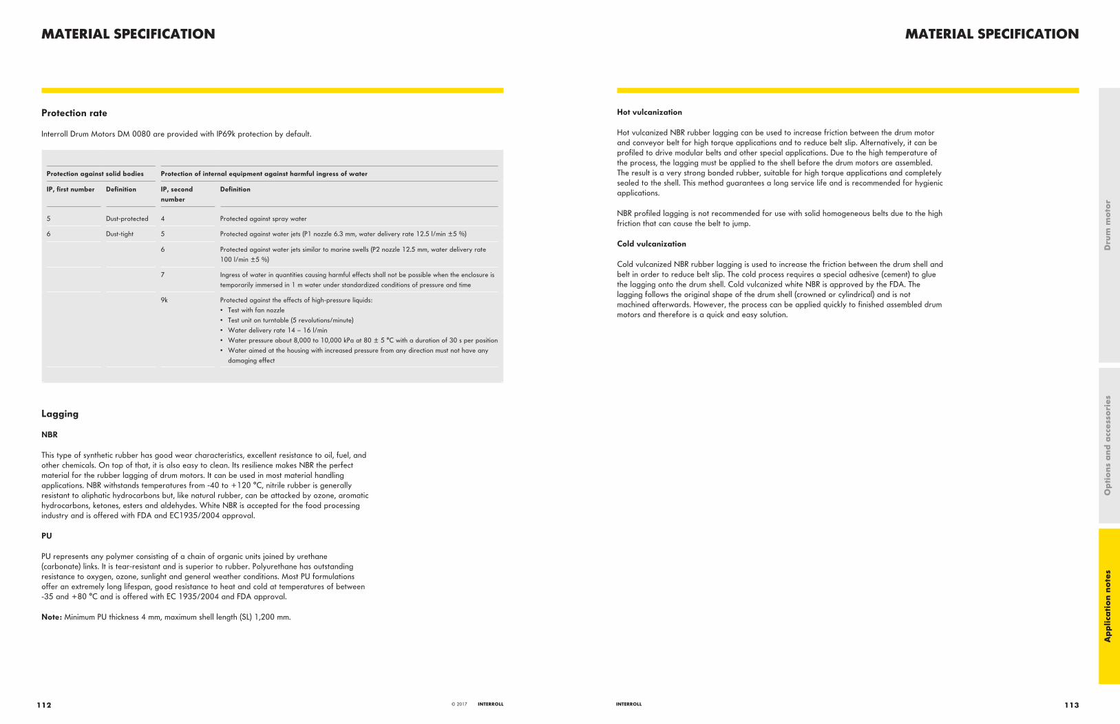
MATERIAL SPECIFICATIONMATERIAL SPECIFICATION
113INTERROLL112 INTERROLL© 2017
Protection rate
Interroll Drum Motors DM 0080 are provided with IP69k protection by default.
Protection against solid bodies Protection of internal equipment against harmful ingress of water
IP, first number Definition IP, second number
Definition
5 Dust-protected 4 Protected against spray water
6 Dust-tight 5 Protected against water jets (P1 nozzle 6.3 mm, water delivery rate 12.5 l/min ±5 %)
6 Protected against water jets similar to marine swells (P2 nozzle 12.5 mm, water delivery rate 100 l/min ±5 %)
7 Ingress of water in quantities causing harmful effects shall not be possible when the enclosure is temporarily immersed in 1 m water under standardized conditions of pressure and time
9k Protected against the effects of high-pressure liquids:• Test with fan nozzle• Test unit on turntable (5 revolutions/minute)• Water delivery rate 14 – 16 l/min• Water pressure about 8,000 to 10,000 kPa at 80 ± 5 °C with a duration of 30 s per position• Water aimed at the housing with increased pressure from any direction must not have any
damaging effect
Lagging
NBR
This type of synthetic rubber has good wear characteristics, excellent resistance to oil, fuel, and other chemicals. On top of that, it is also easy to clean. Its resilience makes NBR the perfect material for the rubber lagging of drum motors. It can be used in most material handling applications. NBR withstands temperatures from -40 to +120 °C, nitrile rubber is generally resistant to aliphatic hydrocarbons but, like natural rubber, can be attacked by ozone, aromatic hydrocarbons, ketones, esters and aldehydes. White NBR is accepted for the food processing industry and is offered with FDA and EC1935/2004 approval.
PU
PU represents any polymer consisting of a chain of organic units joined by urethane (carbonate) links. It is tear-resistant and is superior to rubber. Polyurethane has outstanding resistance to oxygen, ozone, sunlight and general weather conditions. Most PU formulations offer an extremely long lifespan, good resistance to heat and cold at temperatures of between -35 and +80 °C and is offered with EC 1935/2004 and FDA approval.
Note: Minimum PU thickness 4 mm, maximum shell length (SL) 1,200 mm.
Hot vulcanization
Hot vulcanized NBR rubber lagging can be used to increase friction between the drum motor and conveyor belt for high torque applications and to reduce belt slip. Alternatively, it can be profiled to drive modular belts and other special applications. Due to the high temperature of the process, the lagging must be applied to the shell before the drum motors are assembled. The result is a very strong bonded rubber, suitable for high torque applications and completely sealed to the shell. This method guarantees a long service life and is recommended for hygienic applications.
NBR profiled lagging is not recommended for use with solid homogeneous belts due to the high friction that can cause the belt to jump.
Cold vulcanization
Cold vulcanized NBR rubber lagging is used to increase the friction between the drum shell and belt in order to reduce belt slip. The cold process requires a special adhesive (cement) to glue the lagging onto the drum shell. Cold vulcanized white NBR is approved by the FDA. The lagging follows the original shape of the drum shell (crowned or cylindrical) and is not machined afterwards. However, the process can be applied quickly to finished assembled drum motors and therefore is a quick and easy solution.
Ap
plic
ati
on
note
sO
pti
ons
and
acc
esso
ries
Dru
m m
oto
r
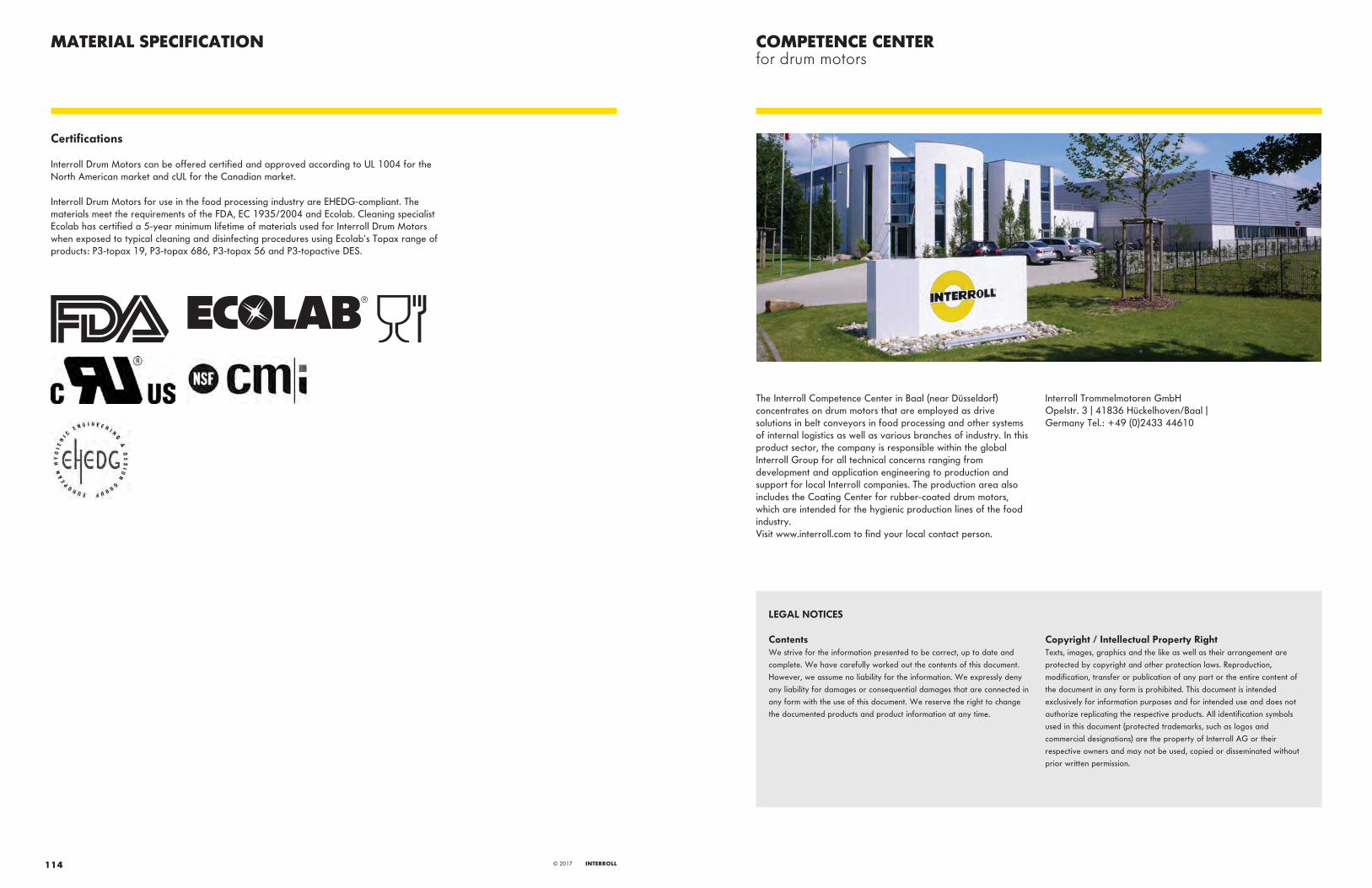
The Interroll Competence Center in Baal (near Düsseldorf) concentrates on drum motors that are employed as drive solutions in belt conveyors in food processing and other systems of internal logistics as well as various branches of industry. In this product sector, the company is responsible within the global Interroll Group for all technical concerns ranging from development and application engineering to production and support for local Interroll companies. The production area also includes the Coating Center for rubber-coated drum motors, which are intended for the hygienic production lines of the food industry.Visit www.interroll.com to find your local contact person.
Interroll Trommelmotoren GmbHOpelstr. 3 | 41836 Hückelhoven/Baal |Germany Tel.: +49 (0)2433 44610
MATERIAL SPECIFICATION
LEGAL NOTICES
ContentsWe strive for the information presented to be correct, up to date and complete. We have carefully worked out the contents of this document. However, we assume no liability for the information. We expressly deny any liability for damages or consequential damages that are connected in any form with the use of this document. We reserve the right to change the documented products and product information at any time.
Copyright / Intellectual Property RightTexts, images, graphics and the like as well as their arrangement are protected by copyright and other protection laws. Reproduction, modification, transfer or publication of any part or the entire content of the document in any form is prohibited. This document is intended exclusively for information purposes and for intended use and does not authorize replicating the respective products. All identification symbols used in this document (protected trademarks, such as logos and commercial designations) are the property of Interroll AG or their respective owners and may not be used, copied or disseminated without prior written permission.
COMPETENCE CENTERfor drum motors
114 INTERROLL© 2017
Certifications
Interroll Drum Motors can be offered certified and approved according to UL 1004 for the North American market and cUL for the Canadian market.
Interroll Drum Motors for use in the food processing industry are EHEDG-compliant. The materials meet the requirements of the FDA, EC 1935/2004 and Ecolab. Cleaning specialist Ecolab has certified a 5-year minimum lifetime of materials used for Interroll Drum Motors when exposed to typical cleaning and disinfecting procedures using Ecolab‘s Topax range of products: P3-topax 19, P3-topax 686, P3-topax 56 and P3-topactive DES.

About InterrollEstablished in 1959, Interroll has grown to become the world‘s leading supplier of key products for internal logistics. Whether boxes, pallets or soft goods are to be handled, no other supplier has such a complete product range on offer. That is why system integrators, OEMs and operators select Interroll as their partner for their internal logistics business. Worldwide. The Interroll global network ensures quick delivery and superior service for every local customer. We inspire our customers and provide opportunities for them to increase efficiency.
interroll.com
INSPIRED BYEFFICIENCY