Drum Filter System Installation and Maintenance ... - … - 1 - INTRODUCTION The Osprey Drum Filter...
64
Drum Filter System Installation and Maintenance Manual
Transcript of Drum Filter System Installation and Maintenance ... - … - 1 - INTRODUCTION The Osprey Drum Filter...

Dr um F i l t e r Sys t emIns t a l l a t i on and Ma in t enance Manua l
Page - 1 -
INTRODUCTION The Osprey Drum Filter is designed to remove fine particulate from the air stream so that clean air may be exhausted back into the manufacturing plant or outside atmosphere. Vacuum nozzles installed in the drum chamber continually clean the drum filter media and the particulate removed from the filter is recycled to the manufacturing process or sent to a waste container. The Drum Filter, which is designed specifically to your application, is sized for the most efficient use of space and power. The Drum Filter will operate automatically on demand of the whole system. Dirty air is introduced into the enclosure on the outside of the drum. Air is then drawn through the filter media where the particulate in the air stream is caught. Clean air is then drawn into the clean air chamber and exhausted. For Drum Filters equipped with an Osprey Final Filter, see the separate installation and maintenance manual for the Final Filter. The Drum Filter media is constantly cleaned by the vacuum nozzle system in the dirty-air side of the enclosure. The vacuum nozzles operate in a sequence governed by the Rotary Diverter Valve (or vacuum nozzle manifold). The particulate vacuumed from the filter media is either recycled into the manufacturing process or collected for waste disposal depending on your manufacturing process. All electrical control components of the drum filter are enclosed in the control panel. Electrical and mechanical sensors for the electrical system are located as necessary on the drum filter or enclosure. Control of drum filter motors is done through this panel. Auxiliary control is interfaced with other plant systems. This manual is written for Osprey Drum Filters and is applicable to all sizes of drum filters. Because of the wide variety of configurations and applications, specific information may be found in the blue Osprey Job Manual supplied with the equipment. Safety information and information of special note are included throughout the manual. Four different types of notes are used in this manual and appear as shown.
-WARNING- Is used to prevent personnel injury.
-CAUTION- Is used to prevent machine damage. -IMPORTANT- Is used to show information that is necessary to insure
proper installation and operation. -NOTE- Is used to provide information of special interest.
TABLE OF CONTENTS
INTRODUCTION .............................................................................................................................1
INSTALLATION ...............................................................................................................................4 Receiving ................................................................................................................................4 Before You Start .....................................................................................................................4 Drum Assembly and Installation ............................................................................................4 Front Drive Drum Installation ....................................................................................9 Rear Drive Drum Installation ......................................................................................10 Drum Seal Installation ............................................................................................................11 Primary Seal Installation .............................................................................................12 Secondary (Continuous) Seal Installation ...................................................................13 Filter Media Installation .........................................................................................................14 Suction Nozzle Installation.....................................................................................................17 Enclosure Installation .............................................................................................................18 Wall Panel Installation ................................................................................................18 Roof Panel Installation ................................................................................................20 Door Installation .........................................................................................................21 Drum Drive Installation ..........................................................................................................21 Rotary Diverter Valve Installation ..........................................................................................23 Fan Installation .......................................................................................................................25 Extended Storage ........................................................................................................25 Handling ......................................................................................................................25 Installation ...................................................................................................................26 Main System Fan ........................................................................................................26 Nozzle Purge Fan ........................................................................................................26 Vibration Isolators .......................................................................................................27 R.I.S. Isolator Installation ...........................................................................................27 Octi Spring Isolator Installation ..................................................................................27 Basic Fire Protection System Installation...............................................................................28 Installation Technical Data for Basic Fire Protection .................................................29 Fluorescent Lighting Installation ............................................................................................32
OPTIONAL EQUIPMENT INSTALLATION ..................................................................................34 DeflagrationVentPanels ........................................................................................................34 Latch Release Pressure ...............................................................................................34 Mounting .....................................................................................................................35 DuctingDeflagrationVentPanels ...............................................................................36 Auto Lubricator System .........................................................................................................36 Electrical Control Panels ........................................................................................................39
INITIAL CHECKS AND RUN-IN PROCEDURE ...........................................................................40
Page –2–
OPERATION .....................................................................................................................................41
General Operation ..................................................................................................................41 Rotary Diverter Valve .............................................................................................................41 Basic Fire Protection ..............................................................................................................41 DeflagrationVentPanels(optionalequipment) ......................................................................42 WarningsandLimitationforDeflagrationVentPanels ..........................................................42
MAINTENANCE ..............................................................................................................................44 Preventative Maintenance ......................................................................................................44 Filter Media Maintenance.......................................................................................................44 Setting and Maintaining Nozzles............................................................................................46 Lubrication Schedules ............................................................................................................46 Drum Seals ..................................................................................................................47 Final Checks ................................................................................................................48 Adjusting the Operating Pressure ...............................................................................48 Setting the Control Timer ............................................................................................48 Speed Reducer ........................................................................................................................48 Factory Filling .............................................................................................................49 Ambient Temperature .................................................................................................49 Oil Changing ...............................................................................................................49 Initial Oil Change ........................................................................................................49 SubsequentOilChanges .............................................................................................49 Synthetic Oils ..............................................................................................................49 LongTermStorageorInfrequentOperation ...............................................................50 Low Input Speeds (under 1160 RPM) ........................................................................50 Oil Temperature ..........................................................................................................50 Overloads ....................................................................................................................50 OverfillingorUnderfilling .........................................................................................51 InadequateCooling .....................................................................................................51 Oil Seals ......................................................................................................................51 Recommended Lubricants for Speed Reducers ..........................................................52 System Fans ............................................................................................................................53 Fan Bearing Maintenance ...........................................................................................53 Motor Maintenance .....................................................................................................54 V-Belt Drive Maintenance ..........................................................................................55 Basic Fire Protection Maintenance .........................................................................................55 Fluorescent Lighting ...............................................................................................................56 Auto-Lubricator(optionalequipment) ...................................................................................56 DeflagrationVentPanels(optionalequipment) ......................................................................57 Drum Filter Sanitation ............................................................................................................57
TROUBLESHOOTING GUIDE .......................................................................................................59General Troubleshooting ....................................................................................................................59System Fan Troubleshooting..............................................................................................................62
PARTS LISTS AND ORDERING .....................................................................................................63Page –3–
Page - 4 -
INSTALLATION Receiving It is in the best interest of the customer to carefully inspect all shipments before they are accepted from the freight carrier. Upon delivery, be sure that all items listed on the bill of lading and packing list have been received. Partial shipments are sometimes made. Even though all equipment is carefully inspected and prepared for shipment at the factory, rough handling en route may cause damage to equipment parts. Any shortage, breakage, or damage noticed at time of delivery should be indicated to the carrier at once. Request their inspection of the shipment and fill out a concealed damage inspection report. Read ”What to do if your shipment if damaged, lost, or stolen!” for more information. Before You Start Determine the location for the Drum Filter according to proper authority and process applications. A smooth level installation surface must be provided to ensure proper assembly and operation. Adequate clearance must be provided around the Drum Filter for periodic maintenance and service.
-NOTE- All drum and enclosure components should be uncrated in the general area of installation and inventoried. Verify that all components are present before beginning installation. This can be accomplished by cross checking individual crate tags with the shipping list. Contact Osprey Corporation with shortages and/or questions. Confirm that the proper floor anchors (hardware) supplied by customer are available. Installation tools to be supplied by customer.
-IMPORTANT- Carefully read through this manual before beginning assembly.
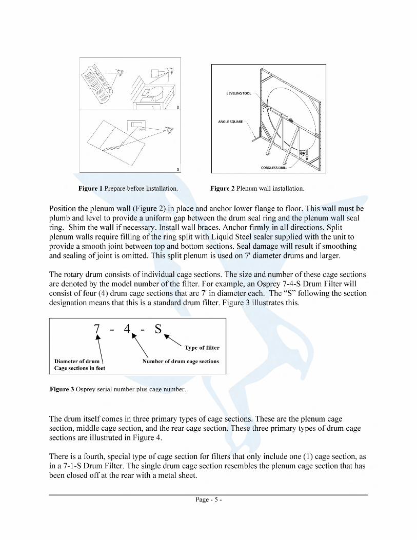
Drum Assembly and Installation Determine component/equipment arrangement and establish critical locations for major items and mark on floor in appropriate manner (Figure 1). Consult customer and/or Osprey drawings for details (Footprint drawings are available from Osprey). Determine RH (right hand) or LH (left hand) location for doors and nozzles.

Page - 6 -
Figure 4 Plenum, center, and rear drum cage sections.
-WARNING- Block the cage sections (Figure 6) during the following procedure to prevent personnel injury by a run-a-way cage section. The sections are heavy and will be dangerous to stop when rolling.
With drum cage sections standing on end arrange the cage sections in proper sequence by following the numbering sequence and aligning the media zipper on each cage. This step must be done on the ground with the shaft not in the bearings. Also, to provide a true round drum, keep the cross bars pointing in the same direction as in Figure 4.
-IMPORTANT- Due to the construction methods, the cage sections must be in proper sequence to provide a true round drum. The cage section is labeled with the serial number followed by the cage position number (Figure 5). This label will be located on the media zipper channel on the inside of the drum. Follow the numbering to prevent damage.
Figure 5 Serial number and sequence plate. Figure 6 Block to prevent drum rolling.

Page - 7 -
Bolt the drum sections together following the numbering sequence. Use 3/8" wiz bolts and nuts. It may be helpful to insert an alignment pin into the bolt holes and clamp together the sections being bolted. Figure 7 illustrates this and Figure 8 shows an assembled drum (8-8).
Place the drum shaft through the cage hubs as in Figure 9. The keyed end of the shaft should extend approximately 12" beyond the hub on the cage section corresponding to the drive location.
-IMPORTANT- Osprey Drum Filters are available in front and rear outside drive configurations. Determine the type of drive configuration for your particular drum filter before proceeding.
Figure 7 Clamp and bolt drum cage sections together. Figure 8 Assembled 8-8 drum.
Figure 9 Insert shaft through drum sections. Figure 10 Shaft in hub with set screws.

Page - 8 -
Insert hub set screws into each shaft hub of the drum, but do not tighten at this time. Final positioning of the shaft will be made later when the drum is installed on the bearing support stands. When installing a drum filter with a front mounted drive, the keyed end of the shaft protrudes from the plenum cage section of the drum (`open end of the drum). When installing a drum filter with a rear outside drive, the keyed end of the shaft protrudes from the rear cage section of the drum (closed end of the drum). Figures 11 and 12 show a rear drive drum and a front drive drum, respectively.
Figure 12 Drum with a front mounted inside drive.
Figure 11 Drum with a rear mounted outside drive.
Page - 9 -
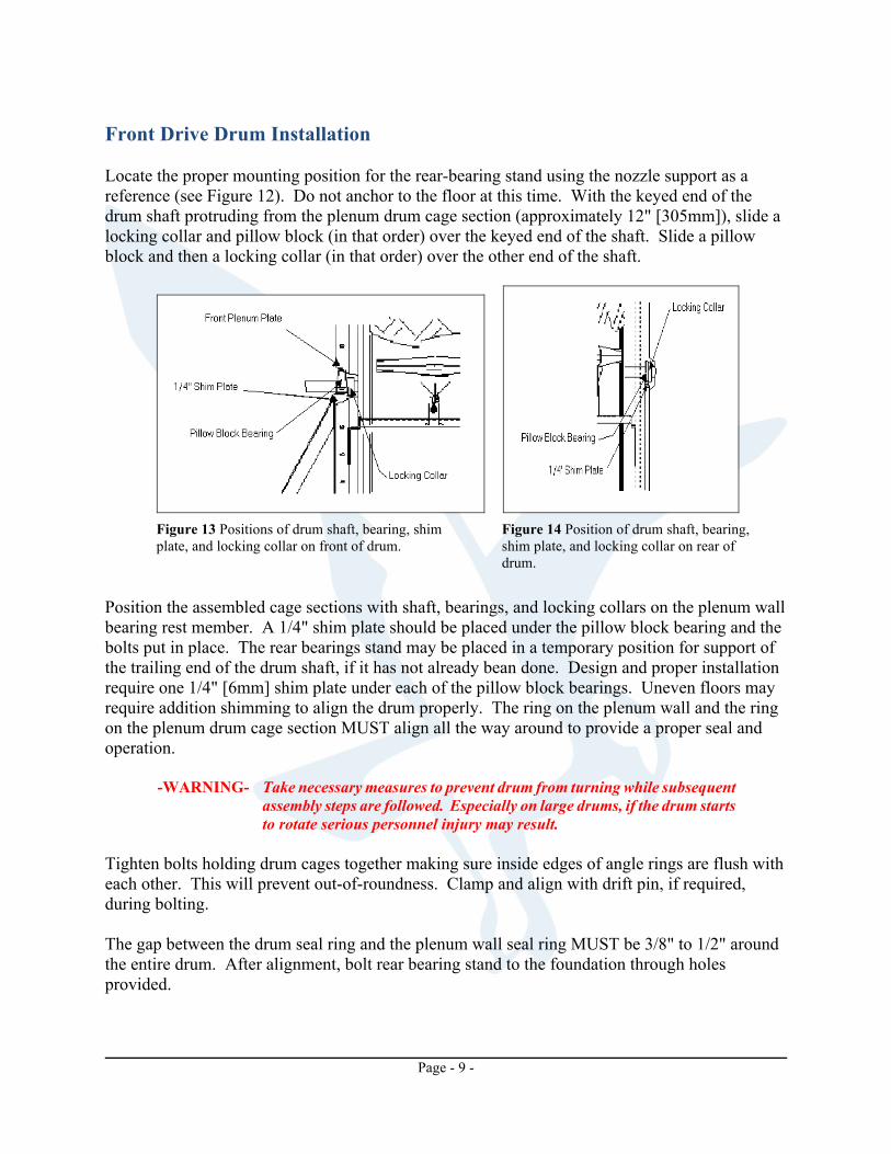
Front Drive Drum Installation Locate the proper mounting position for the rear-bearing stand using the nozzle support as a reference (see Figure 12). Do not anchor to the floor at this time. With the keyed end of the drum shaft protruding from the plenum drum cage section (approximately 12" [305mm]), slide a locking collar and pillow block (in that order) over the keyed end of the shaft. Slide a pillow block and then a locking collar (in that order) over the other end of the shaft.
Position the assembled cage sections with shaft, bearings, and locking collars on the plenum wall bearing rest member. A 1/4" shim plate should be placed under the pillow block bearing and the bolts put in place. The rear bearings stand may be placed in a temporary position for support of the trailing end of the drum shaft, if it has not already bean done. Design and proper installation require one 1/4" [6mm] shim plate under each of the pillow block bearings. Uneven floors may require addition shimming to align the drum properly. The ring on the plenum wall and the ring on the plenum drum cage section MUST align all the way around to provide a proper seal and operation.
-WARNING- Take necessary measures to prevent drum from turning while subsequent assembly steps are followed. Especially on large drums, if the drum starts to rotate serious personnel injury may result.
Tighten bolts holding drum cages together making sure inside edges of angle rings are flush with each other. This will prevent out-of-roundness. Clamp and align with drift pin, if required, during bolting. The gap between the drum seal ring and the plenum wall seal ring MUST be 3/8" to 1/2" around the entire drum. After alignment, bolt rear bearing stand to the foundation through holes provided.
Figure 13 Positions of drum shaft, bearing, shim plate, and locking collar on front of drum.
Figure 14 Position of drum shaft, bearing, shim plate, and locking collar on rear of drum.

Page - 10 -
-CAUTION- Proper alignment is required for a maintenance free operation, so special effort must be given to this step. Improper alignment and clearances will cause severe damage and operational failure.
Figure 15 Align drum with plenum wall so that they are between 3/8” to 1/2” apart around the entire drum. Take the necessary time to ensure this is uniform so that the drum will be sealed properly.
Tighten bearings to mounting plates and install locking collars on bearing inner race flanges. Tighten securely and tighten locking collar set screws.
-IMPORTANT- When drum is in proper alignment, dimple drill the shaft after tightening all components. Remove the set screws from the drum cage section hubs. Place drill and ¼” drill bit into hole and drill slightly into drum shaft. Replace set screws and tighten. Repeat for all drum cage section hubs and set screws. This will help prevent the drum from moving on the shaft while in operation.
Rear Drive Drum Installation Locate the proper mounting position for the rear bearing stand using the markings that were placed on the floor at the beginning of the installation as a guide (see Figure 1). The rear bearing stand is placed just outside of where the enclosure wall panels will be installed. Do not anchor to the floor at this time. With the keyed end of the drum shaft protruding from the rear drum cage section (approximately 12" [305mm]), slide the inside shaft seal plate (if applicable, see section on floating shaft seal installation) and the enclosure wall panel with cutout for drum shaft (in that order) over the keyed end of the shaft. Slide a pillow block bearing and then a locking collar (in that order) over the other end of the shaft.

Page - 11 -
Position the assembled cage sections with shaft, bearings and locking collars on the plenum wall bearing rest member. A 1/4" shim plate should be placed under the pillow block bearing and the bolts put in place. The rear bearings stand may be placed in a temporary position for support of the trailing end of the drum shaft, if it has not already bean done. Design and proper installation require one 1/4" [6mm] shim plate under each of the pillow block bearings. Uneven floors may require additional shimming to align the drum properly. The ring on the plenum wall and the ring on the plenum drum cage section MUST align all the way around to provide a proper seal and operation.
-WARNING- Take necessary measures to prevent drum from turning while subsequent assembly steps are followed. Especially on large drums, if the drum starts to rotate serious personnel injury may result.
Tighten bolts holding drum cages together making sure inside edges of angle rings are flush with each other. This will prevent out-of-roundness. Clamp and align with drift pin, if required, during bolting. The gap between the drum seal ring and the plenum wall seal ring MUST be 3/8" to 1/2" around the entire drum. After alignment, bolt rear bearing stand to the foundation through holes provided.
-CAUTION- Proper alignment is required for a maintenance free operation, so special effort must be given to this step. Improper alignment and clearances will cause severe damage and operational failure.
Tighten bearings to mounting plates and install locking collars on bearing inner race flanges. Tighten securely and tighten locking collar set screws. -IMPORTANT- When drum is in proper alignment, dimple drill the shaft after
tightening all components. Remove the set screws from the drum cage section hubs. Place drill and drill bit into hole and drill slightly into drum shaft. Replace set screws and tighten. Repeat for all drum cage section hubs and set screws. This will help prevent the drum from moving on the shaft while in operation.
Drum Seal Installation Osprey Drum Filters have two separate seals to insure the highest air quality possible. The primary seal is a flat impregnated cotton strip that bridges the gap between the seal ring on the back of the front plenum wall and the matching seal ring on the front of the drum cage assembly. The secondary seal is a continuous rubber or silicone seal the fits on top of the primary seal on seals against the plenum wall.

Page - 12 -
Primary Seal Installation Determine the direction of drum rotation. Most applications will have the drum rotating down from above the vacuum nozzle(s). Example: Media will be loaded/dirty above nozzles. Media will be vacuumed/cleaned below nozzles.
Measure cotton belting primary seal for proper length by wrapping material around drum and cutting at least 6" past starting end (plus 1" for each additional foot of drum diameter above 6 foot diameter). Place one end of cotton seal 2" to 3" past a fastener hole with leading edge of cotton belting facing direction of rotation. The drum section side of this seal should be aligned with the joint between angle rings. This will place the sealing side of seal approximately 1/2" (minimum) from plenum wall seal ring. This 1/2" gap is required for the proper installation of the continuous seal. Drill through the cotton belt seal from the inside of the drum seal ring using the pre-punched hole as a drill guide. A wooden block must be held firmly against the cotton belt to provide accurate drilling. From the outside of the drum, place a fastener in the seal at this time. Smooth side of fastener will be on the outside of the drum. Tighten a nut onto the end of the fastener (10-24 x 3/4" screws) from inside the drum. Rotate the drum, drill and fasten at each pre-punched hole in sequence keeping seal flat and aligned. Overlap trailing edge over the leading edge at least as far as the second bolt. The trailing edge need not be bolted down.
-CAUTION- This seal must be installed so that the trailing edge of the seal is on the
plenum wall angle ring and corresponds with the direction of rotation. You may wish to lubricate seal at this time by putting 1 in3 of powdered silicone in between the primary seal and the plenum wall seal ring. To do this, simply lift the edge of the primary seal over the plenum wall seal ring and apply the silicone. Do not put all of the silicone in one place. Distribute around the entire seal.
Figure 16 Wrap direction of drum primary seal in relation to drum rotation.
Figure 17 Beginning of drum primary seal installation.
Page - 13 -
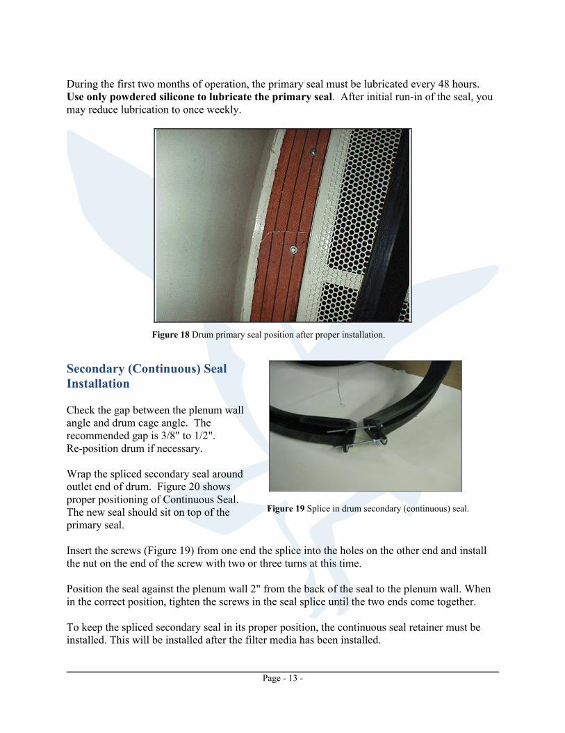
During the first two months of operation, the primary seal must be lubricated every 48 hours. Use only powdered silicone to lubricate the primary seal. After initial run-in of the seal, you may reduce lubrication to once weekly.
Secondary (Continuous) Seal Installation Check the gap between the plenum wall angle and drum cage angle. The recommended gap is 3/8" to 1/2". Re-position drum if necessary. Wrap the spliced secondary seal around outlet end of drum. Figure 20 shows proper positioning of Continuous Seal. The new seal should sit on top of the primary seal. Insert the screws (Figure 19) from one end the splice into the holes on the other end and install the nut on the end of the screw with two or three turns at this time. Position the seal against the plenum wall 2" from the back of the seal to the plenum wall. When in the correct position, tighten the screws in the seal splice until the two ends come together. To keep the spliced secondary seal in its proper position, the continuous seal retainer must be installed. This will be installed after the filter media has been installed.
Figure 18 Drum primary seal position after proper installation.
Figure 19 Splice in drum secondary (continuous) seal.

Page - 14 -
If your Drum Filter was supplied with a rubber secondary seal, this would be a good time to lubricate the secondary seal. This is accomplished by placing approximately one cubic inch of powdered silicone (supplied by Osprey) evenly distributed between the secondary seal and the plenum wall. Do not place the silicone in one place. Distribute around the entire seal. -CAUTION- Use ONLY powdered silicone to lubricate the secondary seal. Any failure to lubricate the seal correctly may result in premature failure of the drive speed reducer. Filter Media Installation Most drums are supplied with a one piece media blanket constructed of a high pile knit fabric. This blanket should reach end-to-end and completely around the drum.
.
Figure 20 Primary and secondary drum seals in proper place.
Figure 21 Layout the filter media with the high pile side facing as shown.
Figure 22 Place edge of filter media in zipper channel using zipper tool. Be sure that the pile side of the media is facing out.
Page - 15 -
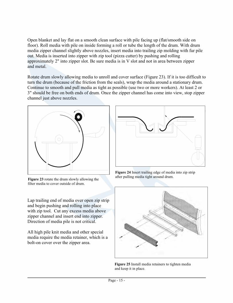
Open blanket and lay flat on a smooth clean surface with pile facing up (flat/smooth side on floor). Roll media with pile on inside forming a roll or tube the length of the drum. With drum media zipper channel slightly above nozzles, insert media into trailing zip molding with fur pile out. Media is inserted into zipper with zip tool (pizza cutter) by pushing and rolling approximately 2" into zipper slot. Be sure media is in V slot and not in area between zipper and metal. Rotate drum slowly allowing media to unroll and cover surface (Figure 23). If it is too difficult to turn the drum (because of the friction from the seals), wrap the media around a stationary drum. Continue to smooth and pull media as tight as possible (use two or more workers). At least 2 or 3" should be free on both ends of drum. Once the zipper channel has come into view, stop zipper channel just above nozzles.
Lap trailing end of media over open zip strip and begin pushing and rolling into place with zip tool. Cut any excess media above zipper channel and insert end into zipper. Direction of media pile is not critical. All high pile knit media and other special media require the media retainer, which is a bolt-on cover over the zipper area.
Figure 23 rotate the drum slowly allowing the filter media to cover outside of drum.
Figure 24 Insert trailing edge of media into zip strip after pulling media tight around drum.
Figure 25 Install media retainers to tighten media and keep it in place.
Page - 16 -
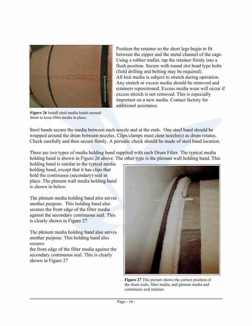
Position the retainer so the short legs begin to fit between the zipper and the metal channel of the cage. Using a rubber mallet, tap the retainer firmly into a flush position. Secure with round slot head type bolts (field drilling and bolting may be required). All knit media is subject to stretch during operation. Any stretch or excess media should be removed and retainers repositioned. Excess media wear will occur if excess stretch is not removed. This is especially important on a new media. Contact factory for additional assistance.
Steel bands secure the media between each nozzle and at the ends. One steel band should be wrapped around the drum between nozzles. Clips/clamps must clear nozzle(s) as drum rotates. Check carefully and then secure firmly. A periodic check should be made of steel band location. There are two types of media holding band supplied with each Drum Filter. The typical media holding band is shown in Figure 26 above. The other type is the plenum wall holding band. This holding band is similar to the typical media holding band, except that it has clips that hold the continuous (secondary) seal in place. The plenum wall media holding band is shown in below. The plenum media holding band also serves another purpose. This holding band also secures the front edge of the filter media against the secondary continuous seal. This is clearly shown in Figure 27 The plenum media holding band also serves another purpose. This holding band also secures the front edge of the filter media against the secondary continuous seal. This is clearly shown in Figure 27
Figure 26 Install steel media bands around drum to keep filter media in place.
Figure 27 This picture shows the correct position of the drum seals, filter media, and plenum media and continuous seal retainer.

Page - 17 -
Special Osprey drum filters and/or conversions to other equipment may be equipped with high pile filter media utilizing a heavy zipper for the length-wise seam. Elimination of center band(s) and special nylon tape may be required. Contact factory for details. Suction Nozzle Installation In the standard drum filter, suction nozzles are mounted on hanging nozzle support assemblies as shown in Figure 28. For this configuration, the nozzle support brackets are bolted to the roof panels. The brackets are positioned so that the nozzles are located in the CENTER of each drum cage section. Drums with more than four nozzles will have a support channel that bolts to the inside of the roof panels to reinforce the enclosure.
When mounting the nozzle support assemblies, refer to the Osprey job manuals for dimensions on where the brackets are to be mounted in relation to the drum. The location of this bracket is critical to ensure that the nozzles can be properly positioned against the media.
When filter media is installed, adjust nozzles to clear the filter media by 3/8". You should be able to slip your fingers (to the middle joint) between the drum filter media and the nozzle slot. Adjust in or out as required by process. The nozzle is adjusted by using the bolt on the top of the bracket to adjust the angle of the support swing arm. Tighten the bolt to push the arm and nozzle away from the drum. Loosen the bolt to allow the arm and nozzle to move in toward the drum.
-CAUTION- Proper end must be on wall bracket to allow nozzle to position on centerline of drum cage section.
On outside drive drum filters, bolt the nozzle support wall brackets on the front plenum wall and the corresponding rear enclosure wall panel (this may require field location and drilling). Bolt the nozzle support assemblies on the nozzle support channel, then the nozzles to the support assemblies.
Figure 28 Suction nozzle mounted on adjustable nozzle support assembly. These are then mounted to the horizontal nozzle support channel. Notice the position of the suction nozzle in relation to the media and media holding bands.

Page - 18 -
When filter media is installed, adjust nozzles to clear the filter media by 3/8". You should be able to slip your fingers (to the middle joint) between the drum filter media and the nozzle slot. Adjust in or out as required by process. Tighten the nozzles on the nozzle support assemblies. Enclosure Installation Before beginning assembly, completely read the following instructions. Check complete enclosure shipment to ensure that all panels have been received using the shipping list and the panel layout drawing found in the blue Osprey Job Manual included in the shipment. Utilizing the enclosed panel layout drawing, mark the outline of the enclosure on the mounting surface by using a chalk line or similar method (if not already marked). Wall Panel Installation For convenience, assemble the wall panels beginning at the drum plenum wall and work back toward the rear of the filter. Locate the plenum wall flashing panel (if applicable) on the enclosure layout drawing and the physical panel in the shipment. Stand the panel up next to the plenum wall.
-NOTE- All wall and roof panels are labeled with a tag for proper installation location. These tags are always located at the top of the panel. Follow proper numbering sequence during installation.
Run a bead of silicone caulk (provided with equipment) on the mating flanges. Press the two flanges together, securing with 3/8"-16 wiz nuts and bolts. Figure 29 shows an exploded view of a typical drum filter enclosure. Repeat this procedure for all wall panels; keeping the wall panels in line with the mark that was put on the floor earlier.
-IMPORTANT- A continuous check should be made to ensure that these walls are square with each other and level. Shimming may be required utilizing metal or wood shims of appropriate thickness. Expandable caulk may be used to cover large variations.
A filter enclosure layout drawing is included with every shipment, and is located inside the blue Osprey Job Manual that shipped with the equipment. Follow this layout drawing carefully. Work from the drum plenum wall toward the back of the enclosure, and then from the drum

Page - 19 -
plenum wall forward toward the clean air wall. Make sure silicone is placed between each panel to ensure an air-tight seal.
-IMPORTANT- Be careful to silicone between each wall panel to ensure an air tight seal and proper drum operation.
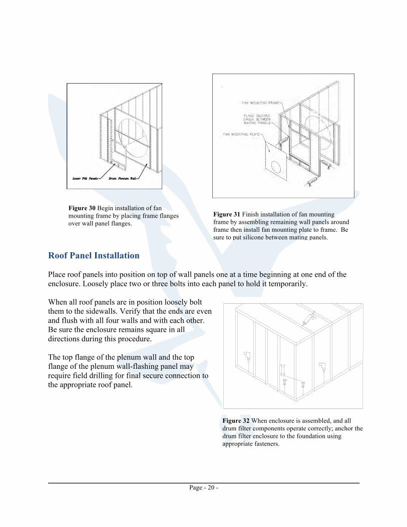
When the front clean air wall is reached, the fan-mounting frame is installed (see Figure 29). This frame is made to fit over the side, lower, and upper parts of the respective panels. It is held in place when the surrounding panels are secured to each other. When one of the side panels and the lower panels are installed, put silicone around the fan-mounting frame and position the fan-mounting frame so that the wall panels fit inside its flanges (Figure 30). Then install the upper panels and the wall panel to the frame’s other side (Figure 31).
Figure 29 Example of an enclosure panel layout drawing. All enclosure panels are tagged with the part number shown in the upper right corner of the layout drawing. The tag is placed on the top of the panel.
Page - 20 -
Figure 30 Begin installation of fan mounting frame by placing frame flanges over wall panel flanges.
Figure 31 Finish installation of fan mounting frame by assembling remaining wall panels around frame then install fan mounting plate to frame. Be sure to put silicone between mating panels.
Roof Panel Installation Place roof panels into position on top of wall panels one at a time beginning at one end of the enclosure. Loosely place two or three bolts into each panel to hold it temporarily. When all roof panels are in position loosely bolt them to the sidewalls. Verify that the ends are even and flush with all four walls and with each other. Be sure the enclosure remains square in all directions during this procedure. The top flange of the plenum wall and the top flange of the plenum wall-flashing panel may require field drilling for final secure connection to the appropriate roof panel.
Figure 32 When enclosure is assembled, and all drum filter components operate correctly; anchor the drum filter enclosure to the foundation using appropriate fasteners.

Page - 21 -
Anchor the walls to the mounting surface by drilling through the pre-punched holes in the base flange of each panel from the outside of the enclosure. Silicone caulking is supplied with each Osprey drum filter enclosure. This caulking will generally be a gray or white material that will allow an excellent seal but will prevent any light from entering the enclosure, which would trigger the optional infrared fire protection system if installed. Caulking/sealing should be accomplished after total assembly of the enclosure and drum filter. Panels that will be inaccessible after assembly must be caulked as assembly progresses. The panels should be first caulked on the outside for negative pressure enclosures and on the inside for positive pressure enclosures. It is recommended that both internal and external joints be caulked along the companion seams if the caulking supply is adequate. Door Installation Place preassembled door and frame in the panel opening and secure in place. Match drill all four corners of door and frame assembly with the enclosure panel flanges and bolt securely in place utilizing the 3/8"-16 wiz bolts and nuts included. Drum Drive Installation
-WARNING- Be sure the electrical system is off and locked out before proceeding.
The drive configurations for drum filters will differ slightly depending on if the unit is a standard Drum Filter or is equipped with a rear outside drive. On the standard front drive unit, mount motor/reducer mounting plate on plenum wall. Mount motor and reducer on the mounting plate loosely. Install belt pulleys on the motor and reducer, and the chain sprockets on the reducer and drum shaft loosely. Align the belt pulleys on the motor and reducer with a straight edge and tighten set screws. Be sure of proper alignment to prevent premature belt failure. Align chain sprockets with straight edge and tighten set screws. Be sure of proper alignment to prevent premature chain failure.
-IMPORTANT- Proper alignment of belt, pulleys, chain, and sprockets will ensure proper operation and prevent premature failure of drive components.
Install chain on sprockets and tighten appropriately using idler assembly. Install belt on pulleys and tighten appropriately by moving the motor in the slotted holes. Tighten the motor to the mounting plate when belt tension is correct. Ideal tension is the lowest tension at which the belt will not slip under peak load conditions.
-NOTE- The ratio of deflection to belt span should be 1:64.

Page - 22 -
Follow the drive assembly drawings in the blue Osprey Job Manual that shipped for proper positioning of the drive belts. If the belt is installed in any other manner, improper operation and damage may occur. When new belts are installed, the tension should be checked every four hours for the first week to allow for run-in time. The outside drive assembly is similar to the standard inside drive assembly with the exception that the drive is mounted outside the rear of the enclosure. Another difference is that a shaft seal plate is installed to prevent air from escaping through the hole cut in the enclosure to accommodate the drum shaft. Make sure that this shaft seal is installed before the drive assembly begins. It is very difficult to install the shaft seal after the drive components are installed. There are two types of shaft seals, the fixed seal and the floating shaft seal. Which comes with your drum filter is dependent on the model and application.
-NOTE- Specific information the shaft seal can be found in the blue Osprey Job Manual that shipped with the equipment.
A fixed type of shaft seal is shown below. To install, slide the rubber gasket over the drum shaft until it is touching the enclosure. Place the metal seal plates over the rubber gasket. If your enclosure is fitted with screw studs for mounting the shaft seal, line up the holes in the rubber gasket and the metal seal plates with the screws in the enclosure then secure with the appropriate nuts. If your enclosure is not fitted with screw studs, then drill through the holes around the edges of the seal plates into the filter enclosure. Secure seal plates and rubber gasket with hardware provided.
Figure 33 Acceptable belt deflection.
Figure 34 Fixed drum shaft seal installation. Figure 35 Floating drum shaft seal installation.

Page - 23 -
A floating type seal is shown in the Figure above. The difference with this seal is that it does not secure directly to the filter enclosure and drilling holes is not required. The floating type of shaft seal consists of an inside seal plate, a rubber gasket, and an outside seal plate. The inside seal plate should already be in place if the assembly of the drum was completed correctly. (When assembling the drum, the inside seal plate and then the enclosure wall panel with the shaft cutout are slid over the keyed end of the shaft before mounting the shaft to the bearing and bearing stand.) Slide the rubber gasket over the drum shaft, followed by the outside seal plate. Line up the holes in the rubber gasket and outside seal plate with the screw studs of the inside seal plate. When the drum is installed and aligned properly, screw the assembly together using 3/8"-16 wiz nuts provided. Rotary Diverter Valve Installation Most Osprey Drum Filters include a Rotary Diverter Valve (RDV) as shown in Figure 36 below. The RDV is designed to regulate the purge air from the vacuum nozzles, offering lower energy consumption and purge air volumes than previous manifold designs.
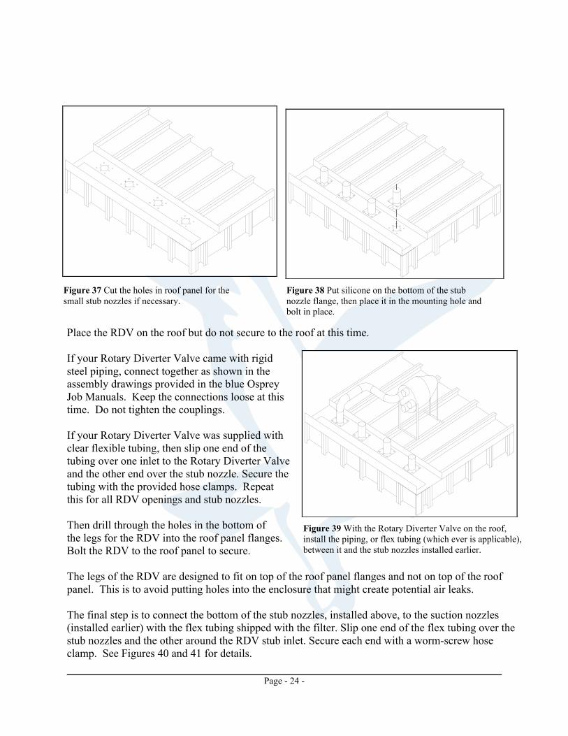
Figure 36 Rotary Diverter Valve (RDV). The first step is to install the small stub nozzles into the provided openings in the inlet roof panel as shown in Figures 37 and 38, then secure with the bolts and nuts provided. (Some drum filters may require field drilling of the holes for the small stub nozzles.)
Page - 24 -
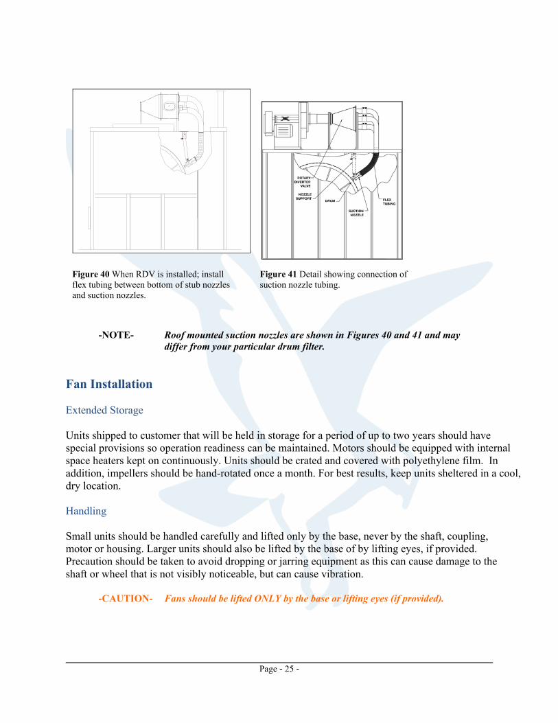
Place the RDV on the roof but do not secure to the roof at this time. If your Rotary Diverter Valve came with rigid steel piping, connect together as shown in the assembly drawings provided in the blue Osprey Job Manuals. Keep the connections loose at this time. Do not tighten the couplings. If your Rotary Diverter Valve was supplied with clear flexible tubing, then slip one end of the tubing over one inlet to the Rotary Diverter Valve and the other end over the stub nozzle. Secure the tubing with the provided hose clamps. Repeat this for all RDV openings and stub nozzles. Then drill through the holes in the bottom of the legs for the RDV into the roof panel flanges. Bolt the RDV to the roof panel to secure. The legs of the RDV are designed to fit on top of the roof panel flanges and not on top of the roof panel. This is to avoid putting holes into the enclosure that might create potential air leaks. The final step is to connect the bottom of the stub nozzles, installed above, to the suction nozzles (installed earlier) with the flex tubing shipped with the filter. Slip one end of the flex tubing over the stub nozzles and the other around the RDV stub inlet. Secure each end with a worm-screw hose clamp. See Figures 40 and 41 for details.
Figure 39 With the Rotary Diverter Valve on the roof, install the piping, or flex tubing (which ever is applicable), between it and the stub nozzles installed earlier.
Figure 37 Cut the holes in roof panel for the small stub nozzles if necessary.
Figure 38 Put silicone on the bottom of the stub nozzle flange, then place it in the mounting hole and bolt in place.
Page - 25 -
-NOTE- Roof mounted suction nozzles are shown in Figures 40 and 41 and may
differ from your particular drum filter. Fan Installation Extended Storage Units shipped to customer that will be held in storage for a period of up to two years should have special provisions so operation readiness can be maintained. Motors should be equipped with internal space heaters kept on continuously. Units should be crated and covered with polyethylene film. In addition, impellers should be hand-rotated once a month. For best results, keep units sheltered in a cool, dry location. Handling Small units should be handled carefully and lifted only by the base, never by the shaft, coupling, motor or housing. Larger units should also be lifted by the base of by lifting eyes, if provided. Precaution should be taken to avoid dropping or jarring equipment as this can cause damage to the shaft or wheel that is not visibly noticeable, but can cause vibration. -CAUTION- Fans should be lifted ONLY by the base or lifting eyes (if provided).
Figure 40 When RDV is installed; install flex tubing between bottom of stub nozzles and suction nozzles.
Figure 41 Detail showing connection of suction nozzle tubing.

Page - 26 -
Installation Fans and motors should be mounted on structurally sound foundations. Concrete is the best, however, other types designed properly are acceptable. Equipment should be leveled on the foundation and be shimmed or grouted in place. This will prevent putting the fan structure into a bind by bolting down on an uneven surface. As a general rule, if vibration isolators are used, the fan should first be bolted to a structural steel base and the foundation. This prevents the fan base from “floating” due to uneven weight distribution and/or forces when mounted directly to vibration isolators. Main System Fan Temporarily position main system fan approximately 12" [305mm] from fan mounting plate. Bolt the flex inlet for the main system fan to the fan mounting plate using the provided hardware. Line the main system fan inlet flange up with the flex inlet flange.
-NOTE- If the bolt holes do not align, loosen the clamp on the flex inlet until the
flange rotates. Rotate the flange until the bolt holes are aligned, then tighten the clamp.
Secure the main system fan to the foundation at this time. If the fan was supplied with vibration isolators, see the section Vibration Isolators.
-NOTE- Anchors to secure the main system fan to the foundation are not supplied by Osprey unless specifically requested in advance. When requesting anchors, specify the foundation material and thickness. Anchors are not included on product quotes and are an additional charge.
When fan is secured to the foundation, bolt main fan flange to the flex inlet flange using the provided hardware. Nozzle Purge Fan Consult the layout drawings for the equipment supplied by Osprey. If Osprey is supplying the ducting, or a specific location is requested, install the vacuum nozzle purge fan in the position indicated on the layout drawings. If no position was requested, the vacuum nozzle purge fan may be mounted in the most convenient location. If mounted on the roof of the Drum Filter enclosure, it should be mounted on auxiliary steel rails and placed as near to the corner of the enclosure as possible to ensure maximum support.
Page - 27 -
-NOTE- Nozzle purge fan roof mounting plates are available from Osprey at additional charge. Mounting the nozzle purge fan on the roof is subject to an Osprey engineer’s approval.
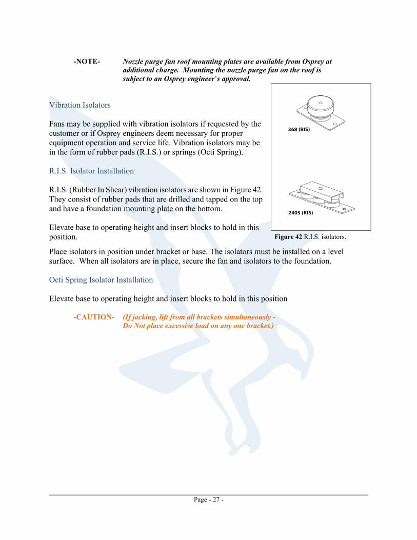
Vibration Isolators Fans may be supplied with vibration isolators if requested by the customer or if Osprey engineers deem necessary for proper equipment operation and service life. Vibration isolators may be in the form of rubber pads (R.I.S.) or springs (Octi Spring). R.I.S. Isolator Installation R.I.S. (Rubber In Shear) vibration isolators are shown in Figure 42. They consist of rubber pads that are drilled and tapped on the top and have a foundation mounting plate on the bottom. Elevate base to operating height and insert blocks to hold in this position.
Place isolators in position under bracket or base. The isolators must be installed on a level surface. When all isolators are in place, secure the fan and isolators to the foundation. Octi Spring Isolator Installation Elevate base to operating height and insert blocks to hold in this position
-CAUTION- (If jacking, lift from all brackets simultaneously - Do Not place excessive load on any one bracket.)
Figure 42 R.I.S. isolators.

Page - 28 -
Place isolators in position under bracket or base. The isolators must be installed on a level surface. Turn lock nut “Y” onto leveling bolt “X” then insert bolt “X” down through hole in bracket or base and into threaded hole in isolator housing. Proceed to adjust isolators by turning the leveling bolt “X” clockwise several turns at a time alternately on each isolator until load is transferred onto springs and base is raised uniformly off blocks. Then remove the blocks. Turn lock nut “Y” clockwise and secure firmly against the top of the bracket or base. Mounts are now properly adjusted and ready for the equipment to be operated. Basic Fire Protection System Installation The sprinkler system is usually shipped as separate pieces and must be assembled. The basic sprinkler system consists of galvanized pipe, galvanized pipe fittings (tees, elbows, etc.), flat washers, and sprinkler heads. The individual parts are listed on the ship list provided by Osprey and also on an assembly drawing included in the blue Osprey Job Manual. Figure 45 shows an example of a sprinkler system assembly drawing for a 4-3-S and 5-3-S drum filter. Follow the assembly drawing for your system to assemble.
Figure 43 Spring isolator. Figure 44 Typical heights for vibration isolators.
Page - 29 -
-NOTE- When assembling, follow all local codes and standards that apply. 1. Assemble the piping as shown in the assembly drawing included in the blue Osprey Job
Manual. Make sure all threaded connections are sealed with pipe compound (commonly referred to as “pipe dope”) to provide a watertight connection.
2. Lay the piping system on top of the equipment using the location shown on the assembly
drawings as a guide.
3. Field locate and cut access holes in the equipment where the sprinkler heads are to be installed. -IMPORTANT- Actual location of the piping and sprinkler heads may differ from what is
shown on the assembly drawings provided. 4. Install the sprinkler heads onto the piping system. 5. Angle piping so that the drain plug is at the lowest point of the piping system. 6. Install additional piping for water supply.
-NOTE- Piping required for water supply is not provided by Osprey.
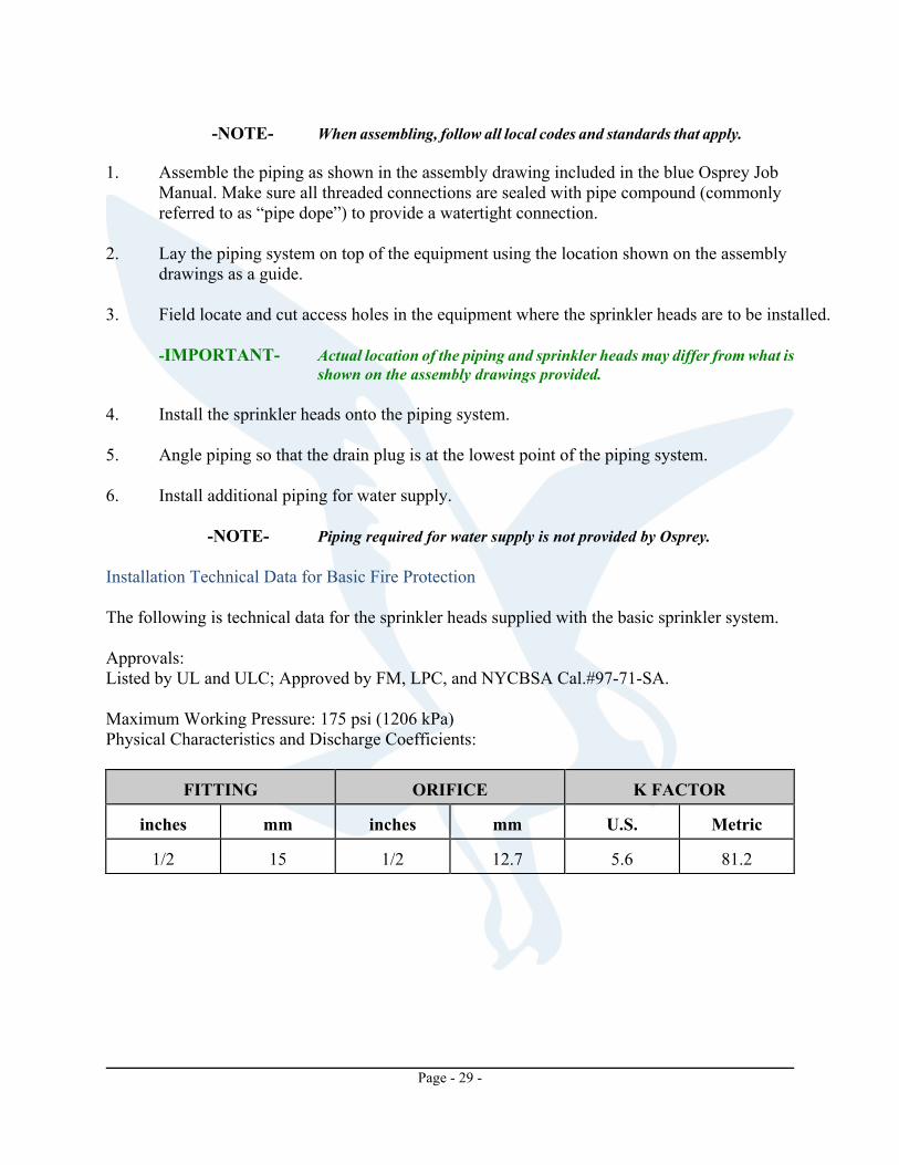
Installation Technical Data for Basic Fire Protection The following is technical data for the sprinkler heads supplied with the basic sprinkler system. Approvals: Listed by UL and ULC; Approved by FM, LPC, and NYCBSA Cal.#97-71-SA. Maximum Working Pressure: 175 psi (1206 kPa) Physical Characteristics and Discharge Coefficients:
FITTING
ORIFICE
K FACTOR
inches
mm
inches
mm
U.S.
Metric
1/2
15
1/2
12.7
5.6
81.2
Page - 30 -
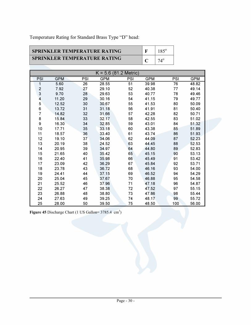
Temperature Rating for Standard Brass Type “D” head: SPRINKLER TEMPERATURE RATING
F
185o
SPRINKLER TEMPERATURE RATING C
74o
Figure 45 Discharge Chart (1 US Gallon= 3785.4 cm3)

Page - 31 -
Figure 46 Example of basic fire protection system for drum filter.
Page - 32 -
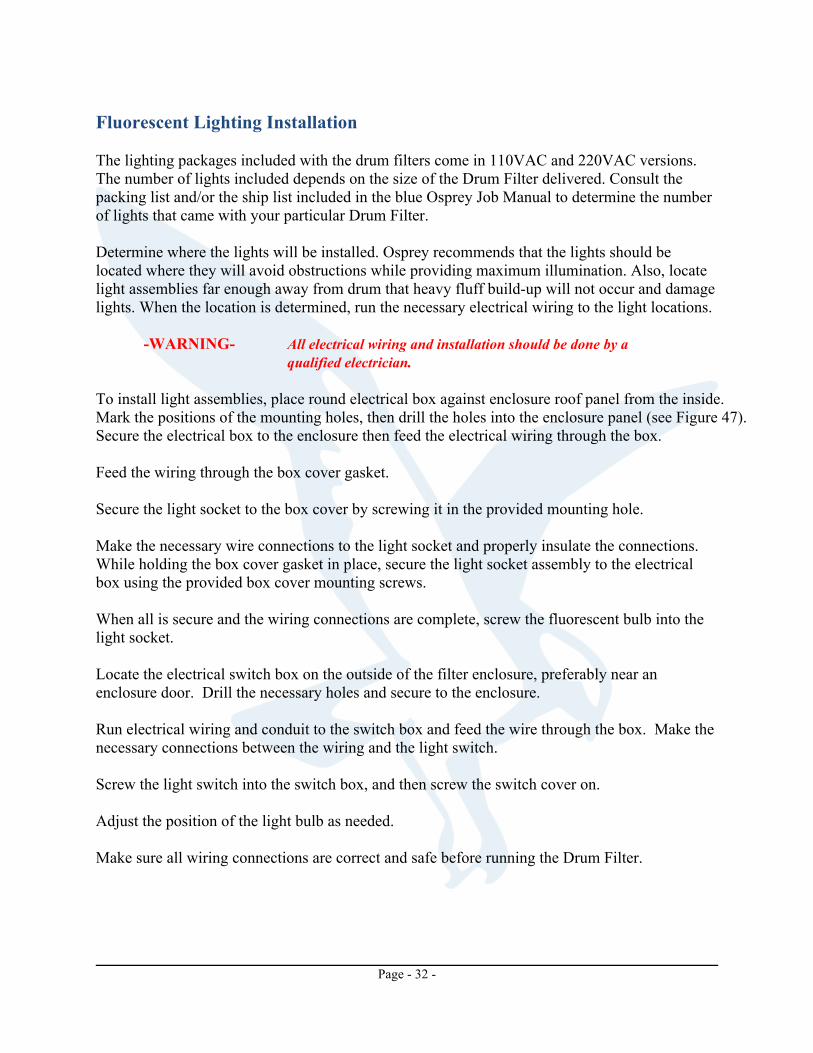
Fluorescent Lighting Installation The lighting packages included with the drum filters come in 110VAC and 220VAC versions. The number of lights included depends on the size of the Drum Filter delivered. Consult the packing list and/or the ship list included in the blue Osprey Job Manual to determine the number of lights that came with your particular Drum Filter. Determine where the lights will be installed. Osprey recommends that the lights should be located where they will avoid obstructions while providing maximum illumination. Also, locate light assemblies far enough away from drum that heavy fluff build-up will not occur and damage lights. When the location is determined, run the necessary electrical wiring to the light locations.
-WARNING- All electrical wiring and installation should be done by a qualified electrician.
To install light assemblies, place round electrical box against enclosure roof panel from the inside. Mark the positions of the mounting holes, then drill the holes into the enclosure panel (see Figure 47). Secure the electrical box to the enclosure then feed the electrical wiring through the box. Feed the wiring through the box cover gasket. Secure the light socket to the box cover by screwing it in the provided mounting hole. Make the necessary wire connections to the light socket and properly insulate the connections. While holding the box cover gasket in place, secure the light socket assembly to the electrical box using the provided box cover mounting screws. When all is secure and the wiring connections are complete, screw the fluorescent bulb into the light socket. Locate the electrical switch box on the outside of the filter enclosure, preferably near an enclosure door. Drill the necessary holes and secure to the enclosure. Run electrical wiring and conduit to the switch box and feed the wire through the box. Make the necessary connections between the wiring and the light switch. Screw the light switch into the switch box, and then screw the switch cover on. Adjust the position of the light bulb as needed. Make sure all wiring connections are correct and safe before running the Drum Filter.

Page - 33 -
Figure 47 Lighting package installation.
Page - 34 -
OPTIONAL EQUIPMENT INSTALLATION Deflagration Vent Panels The Osprey Deflagration Vent Panels provide relief in the event that an internal explosion takes place, and maintain a positive air-tight seal during normal conditions. These panels are usually installed on the top of the equipment where ducting to the outside can be installed. With this configuration, the personnel and equipment damage are kept to a minimum as the force of the explosion is directed towards a safe place. Osprey Deflagration Vent Panels are installed with Brixon latches. These latches are Factory Mutual approved as explosion-venting door latches (page 241, 1988 Factory Mutual Approval Guide). The Osprey Deflagration Vent Panels are pre-installed at the factory. All adjustments are made to the panels to suit the specific application. In most cases, the relief pressure is set just above normal operating pressure. Latch Release Pressure Precise pressure adjustment is not possible due to the location of the strike, the amount of gasket compression, spring differences in a given lot, friction, etc. For this reason, adjustments can be made only after consulting Osprey.
-WARNING- DO NOT make any adjustments to the deflagration vents without consulting Osprey Corporation.
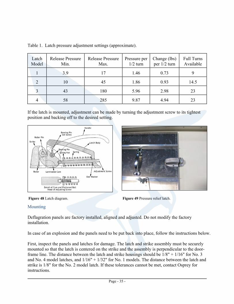
The listed values in the table below are a guide only, and if the release pressure is critical, the pressure must be measured directly for more accuracy. The estimated variance is plus or minus 2 full turns. To adjust, have the latch in the door closed position wherein one rivet that holds the laminated cam together is exposed. See Figures 48 and 49 for latch details. Turn the adjusting screw counter-clockwise to its loosest position, making sure that the square nut does not come off the ball pin. Using the table below as a guide, tighten the adjusting screw a half turn at a time until the desired pressure setting is reached. It should be possible to feel the adjusting screw slipping into the relaxed position at each half turn. For example, if you wanted 107 lbs. pressure setting on a No. 4 latch, tighten the adjusting screw 10 half turns (58 + (10 x 4.94)) = 107.
Page - 35 -
Table 1. Latch pressure adjustment settings (approximate). Latch Model
Release Pressure
Min.
Release Pressure
Max.
Pressure per
1/2 turn
Change (lbs) per 1/2 turn
Full Turns Available
1
3.9
17
1.46
0.73
9
2
10
45
1.86
0.93
14.5
3
43
180
5.96
2.98
23
4
58
285
9.87
4.94
23
If the latch is mounted, adjustment can be made by turning the adjustment screw to its tightest position and backing off to the desired setting.
Mounting Deflagration panels are factory installed, aligned and adjusted. Do not modify the factory installation. In case of an explosion and the panels need to be put back into place, follow the instructions below. First, inspect the panels and latches for damage. The latch and strike assembly must be securely mounted so that the latch is centered on the strike and the assembly is perpendicular to the door-frame line. The distance between the latch and strike housings should be 1/8" + 1/16" for No. 3 and No. 4 model latches, and 1/16" + 1/32" for No. 1 models. The distance between the latch and strike is 1/8" for the No. 2 model latch. If these tolerances cannot be met, contact Osprey for instructions.
Figure 48 Latch diagram. Figure 49 Pressure relief latch.
Page - 36 -
Latches should be tested for proper operation after adjustment, installation, and after an explosion. Ensure that the roller forces the cam of the latch into the fully open position when the door is opened and that the opened can will contact the roller and be forced into the closed position as the door is closed. Failure to do so may cause an unanticipated rebound, since the latch and strike will not engage upon closing. Misalignment of the latch and strike will also cause this rebound. If the strike bends back upon closing, or the body moves toward the hinges, it is possible for the latch to close in the wrong position. This is most likely to happen when the door is slammed (excessively) and/or the latch mechanism is dirty or corroded. In this event, the door may be very difficult to open, either by hand or in the event of an explosion. It is also a warning that maintenance is required and that a hazardous situation exists. Ducting Deflagration Vent Panels If the filter is indoor, ducting should be attached between the deflagration vents and the outside of the building to keep plant personnel and other equipment out of danger. The cross sectional not exceed 3 meters.
-WARNING- Do not allow an explosion to vent indoors. Always duct from the vent panels to a safe location outside of the building.
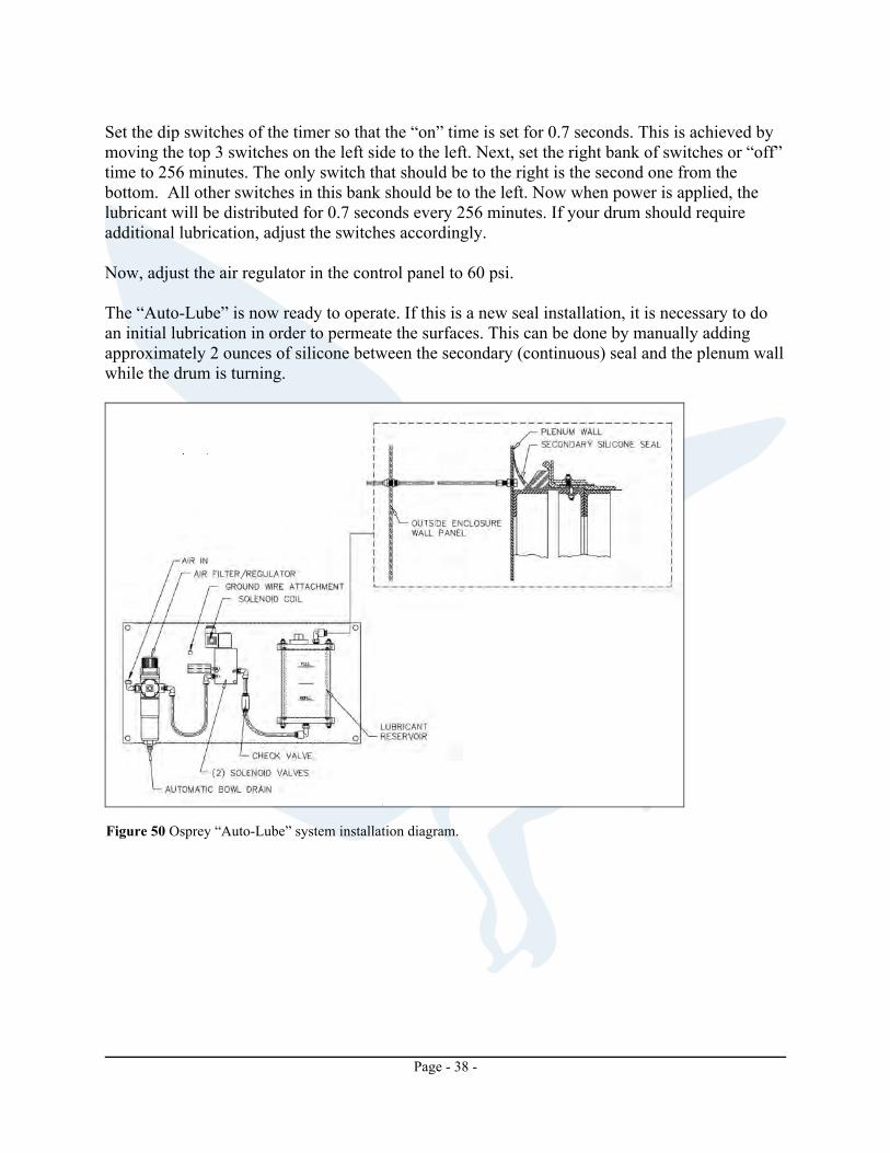
If the filter is outdoors, a vertical duct should be run if height of the filter puts the deflagration vents near to plant personnel or any people that might walk near the filter. Extend the vertical duct to a safe height. Auto Lubricator System The Osprey Autolube delivers dry lubricant to the primary and secondary seals of its rotary drum filter. Lubrication of the seal promotes smooth operation, increased seal life, and lower current draw from the drive motor. A compressed air stream delivers the dry lubricant to the space between the seals and the adjoining wall.
One compressed air inlet to the Autolube will supply the lubricant delivery circuit to the drum filter seals. A compressed air line from the plant (not included) is attached to the inlet of the filter/regulator. The filter/regulator removes moisture from the air supply and adjusts the air pressure to within working limits. The air line exits the filter/regulator and enters a dedicated solenoid valve for the lubricant delivery circuit. The solenoid valve is wired to the Osprey supplied control panel. The compressed air exits the solenoid valve and enters the lubricant reservoir, entrapping lubricant in the air stream. The compressed air then leaves the lubricant reservoir with the suspended lubricant and deposits this between the seals and the plenum wall.
Page - 37 -
The “Auto-Lube” system requires electrical power for the timer. Make sure that you have the correct timer that matches the voltage out of your drum filter electrical control panel. The other requirement for the “Auto-Lube” is compressed air. This should be clean and dry air with a minimum pressure of 80 psi.
-IMPORTANT- The “Auto-Lube” system requires electrical power for the timer. The “Auto-Lube” systems are supplied with specific voltage requirements. Confirm the supply and operating voltages before continuing.
Figure 50 shows an installation diagram for the “Auto-Lube” system. To install the Auto-Lubricator: Mount the control panel in a convenient location. Keep in mind that you must have compressed air coming into the panel and that the regulated compressed air coming out is the conveying force for the lubricant. Mount the silicone tank to the enclosure wall on the nozzle side of the first panel next to the plenum wall on the clean air side. Mount the spray nozzle in the plenum wall on the nozzle side at the 90o position. The hole should be situated so that the flat of the locknut on the dirty air side will be up against the angle ring. Now install the bulkhead coupling in the enclosure wall. Placement of this fitting should be in the same panel where the tank is mounted and about way down. Connect to the bulkhead fitting on the outside. Now that each component is in position, it is necessary to run the compressed air to the marked “air in” fitting on the control panel. Continue the run by starting at the “air out” fitting and connecting it to the bottom fitting of the silicone tank. Continue the run from the upper fitting of the silicone tank to the bulkhead fitting in the enclosure wall. Go inside the enclosure on the clean air side and complete the final tubing run by making the last connection between the bulkhead coupling and the spray nozzle mounted in the plenum wall. Fill the silicone tank. Run the required electrical power to the marked terminals inside the control panel. It is recommended that this power come from the drum filter electrical panel.
Page - 38 -
Set the dip switches of the timer so that the “on” time is set for 0.7 seconds. This is achieved by moving the top 3 switches on the left side to the left. Next, set the right bank of switches or “off” time to 256 minutes. The only switch that should be to the right is the second one from the bottom. All other switches in this bank should be to the left. Now when power is applied, the lubricant will be distributed for 0.7 seconds every 256 minutes. If your drum should require additional lubrication, adjust the switches accordingly. Now, adjust the air regulator in the control panel to 60 psi. The “Auto-Lube” is now ready to operate. If this is a new seal installation, it is necessary to do an initial lubrication in order to permeate the surfaces. This can be done by manually adding approximately 2 ounces of silicone between the secondary (continuous) seal and the plenum wall while the drum is turning.
Figure 50 Osprey “Auto-Lube” system installation diagram.

Page - 39 -
Electrical Control Panels Mount the drum filter control panel at this time. If the drum filter was supplied with an Osprey Final Filter, mount the control panel for the Final Filter also. -WARNING- Osprey recommends that the control panel be positioned so that personnel currently at the control panel can see the equipment without any obstructions in the line of sight. Personnel should be able to see the equipment so that personnel, tools, etc. are clear of the equipment before any action at the control panel is taken. If your system includes a differential pressure warning kit, tube connections should be made now.Also, tubing connections for other pressure monitoring should be made now.
Figure 51 Electrical control panel.

Page - 40 -
INITIAL CHECKS AND RUN-IN PROCEDURE Initiate a final check of all bolts, anchors, and other connectors to ensure that they are located and tightened as specified. Phoenix Filters include a shaft seal plate for the drum shaft. If that has not been installed, do so now according to the factory drawings supplied by Osprey in the blue job manual. Checks should also be made to ensure that all seams are caulked with silicone (provided by Osprey) inside and out. This will ensure an air-tight enclosure. An additional check of the proper location and lubrication of the drum seal as well as door seals is also recommended. Lubricate the primary drum seal at this time if this has not already been done. This is accomplished by placing 1 inch of powdered silicone in between the primary drum seal and the plenum seal ring. Report any deficiencies and/or questions to the factory or your area representative before proceeding further. Proper fan rotation as well as drum rotation should be checked at this time. Likewise, all pneumatic manifolds, cylinders, valves, etc. should be checked as well as any pneumatic diverter gates in the system (if applicable). Check all electrical connections and compare with the electrical drawings provided. If possible, it is recommended that the system be started and operated for a minimum of 24 hours prior to placing in service with production machinery. Experience shows that this method of run-in will eliminate many future operating and maintenance problems.
Page - 41 -
OPERATION General Operation The Osprey Drum Filter is designed to operate without the need for constant operator intervention. The drum filter is interfaced with the rest of the equipment in the plant to allow for automatic operation. Specific information regarding drum filter interfacing can be found in the electrical drawings supplied in the blue Osprey Job Manual. After start-up of the Drum Filter at the beginning of a production period, it continuously cleans process air. Clean air is exhausted and particulate which congregate on the outside of the drum are cleaned away by the vacuum nozzle system and returned to the process or transported to a waste collection system. Air pressure drop across the filter media is monitored constantly by electrical components. If the pressure drop goes beyond the operating parameters, an alert is given. Operation of the filter should be checked periodically by personnel assigned to the task. The mechanical condition of the entire system should be checked. Particular attention should be paid to filter media and seals. Remember that a machine is safest when clean and mechanically sound. Keep the area around the filter to the standards of your plant or local codes to promote a safe environment. Rotary Diverter Valve The speed settings for the Rotary Diverter Valve need to be made in the field. There is a controller installed in the control panel that adjusts the working time allocated for each suction nozzle (reference supplied electrical drawings for proper location). This should be adjusted so that each suction nozzle is active for one revolution of the drum, then switches to the next suction nozzle in sequence. Basic Fire Protection The Basic Fire Protection system offered by Osprey will work without any intervention except for general maintenance. Each of the sprinklers share the same basic operating mechanism, consisting of a fusible alloy sealed in the center of a bronze strut by a stainless steel ball. When the alloy melts and the strut assembly compresses, the sprinkler opens.
Page - 42 -
Because it is sealed within the strut, the operating “heart” of the sprinkler is spared the constant exposure to dust, dirt, and corrosion that might otherwise effect its operation. The operating mechanism is compact and symmetrical, with no protruding links or levers. Deflagration Vent Panels (optional equipment) The latches operate in a manner similar to a toggle switch. When the door and latch are in the closed position, the latch will hold the door closed unless enough pressure is applied to compress the spring sufficiently to cause tripping of the cam into the open position. When the cam is in the open position, the door is free to open. Closing is essentially the reverse of the above, with the force being supplied by the closing of the door. The forces required for operation depend upon the setting of the latch (see AAdjustment@ under INSTALLATION) - the higher the setting and the larger the latch, the greater the required force. In the event of an explosion, the latch will begin to open when the internal pressure equals the setting of the latch. However, due to inertia in the latch-door system, there will be a slight delay between application of pressure and the opening of the door (See NFPA No. 68). This might allow a considerable pressure build-up, depending upon the oven size, type, and amount of material exploding, and the time lag involved. In the event of a maximum violence explosion, the effectiveness of the latches is reduced. However, most explosions are not of maximum violence (FM Approval Guide, 1988, page 240; NFPA 1983 No. 68, p. 32).
-WARNING- Violent slamming is potentially hazardous and must be avoided.
-WARNING- For reasons listed above, the door may not latch when closed. Beware of rebound.
-WARNING- Keep clear of the arc of the door.
-WARNING- Keep clear of the operating parts of the latch and handle (if applicable),
particularly the laminated cam, roller of the strike, the resistance area of Heavy Duty handles, and the stops for standard No. 3 and No. 4 handles.
Warnings and Limitation for Deflagration Vent Panels
-WARNING- The following warnings apply to all Osprey deflagration vents. 1. If the door is closed with insufficient force to trip the cam, the door will rebound. 2. If, for some reason, the cam is in the “closed” position while the door is open, the door
will rebound rather than latching when closed. This could be caused by a misaligned strike (all latches) and/or a loose handle (No. 3 and 4H latches only) or by the cam being struck and rotated accidentally while in the open position.

Page - 43 -
3. If excessive force is used in closing (slamming) the door, the tendency of the door to
rebound may be sufficient to cause the latch (and door) to re-open. A rebounding door would not normally cause a dangerous situation unless some aggravating condition is present, such as violent slamming and/or immobility of the person closing the door, but is essential that operators are aware of the possibility of rebound, and are warned against violent slamming. It is also recommended that the operator should keep his or her hand between his body and the door while closing it. The forces involved, and therefore the hazards increase with the size and setting of the latch.
4. The door may open unexpectedly if material (such as a large casting) should fall and strike the
interior of the door. 5. In the event of an explosion, the door will open rapidly and with little or no warning. It is
therefore recommended that the area in the arc of the door be marked as a danger area, perhaps by red striping, “Danger” signs, etc.
6. The latches should be set at the lowest practical setting. 7. Due to the inherent brittle nature of cast iron, high impact loads may fracture the castings
of the latches, possibly resulting in a flying fragment. This is not expected to occur under normal conditions, but is possible under unusually severe conditions of use.
8. The pressure relief latches will eventually wear to degree where they should be deemed
unusable. The expected life depends strongly upon the conditions of use. If the latch is properly maintained, and in a non-corrosive and dry area, probable failure points are:
a) Cracking of the casting near the bearing pin or base holes because of impact loads. This may result in a hazard in the case of flying fragment. This is not common, but abuse of the latches makes it more likely.
b) The spring may lose temper because of prolonged heating or fatigue. This will
cause the deflagration vent panels to open and/or rebound more easily than normal. 9. If the latch is operated in an exterior or corrosive atmosphere, failure is more likely to be
due to rusting of internal parts and/or the cast housings. Corrosion of internal parts results in the probability of the latch mechanism “freezing” and is a major hazard in the event of an explosion. Corrosion of the casting will render it more prone to cracking or breaking under impact.

Page - 44 -
MAINTENANCE Preventative Maintenance Every day
(1)
Check magnehelic pressure gauge on control panel. It should be between .5" and 1.5" W.G.S.P. A climbing readings indicates that the filter media is starting to block.
(2)
Visually check media and vacuum nozzles.
(3)
Check amount of filtrate on floor. Clean out as necessary.
(4)
Inspect media and seal for looseness or damage.
(5)
Check for proper diverter valve operation.
(6)
Check auto-lube to insure proper level.
Every month
(1)
Check drum drive, including reducer and motor lubrication.
(2)
Check condition of fan belts.
(3)
Visually check system for damage or leaks.
Every 3 months
(1)
Lubricate fan and drum bearings.
-CAUTION- For additional detailed information, see the Osprey Blue Book (job
manual) that was provided with your equipment. Filter Media Maintenance Filter media on the Osprey Drum Filter is most commonly a one piece high pile filter blanket that efficiently collects particulate from the air stream. This filter media is a knit fabric material and will wear and stretch and will tear if proper maintenance and care is not taken. Any lack of care will reduce the efficiency of the filter and could allow particulate matter to pass through the filter media. Interaction of the vacuum nozzles is also critical to proper care and maintenance of the filter media. The vacuum nozzles remove the particulate from the filter media to prevent a build-up of particulate that will clog the filter. If the nozzles are too far from the filter media the vacuum will not remove the particulate. If the nozzles are too close, the filter media may be rubbed and worn or possibly torn by the nozzles. See the vacuum nozzle section for more detailed information on setting the vacuum nozzles.
Page - 45 -
The condition of filter media can be best observed by two methods used together. These are a visual inspection of the filter media combined with observation of the differential in pressure across the filter media. The proper differential pressure is determined by the engineering staff at Osprey. If the pressure is out of the normal limits the cause of the increase or decrease should be determined and corrected before further operation of the drum filter. Higher pressure could be caused by a loaded filter media blanket is described in the following paragraphs. This blanket should reach end-to-end and completely around the drum. Open the blanket and lay it flat on a smooth clean surface with pile facing up (flat/smooth side on floor). Roll media with pile on inside forming a roll or tube the length of the drum. With drum media zipper channel slightly above nozzles insert media into trailing zip molding with fur pile out. Media is inserted into zipper with zip tool (pizza cutter) by pushing and rolling approximately 2" into zipper slot. Be sure media is in V slot and not in area between zipper and metal. Rotate drum slowly allowing media to unroll and cover surface. Continue to smooth and pull media as tight as possible (use two or more workers). At least 2 or 3" should be free on both ends of drum. Once the zipper channel has come into view, stop zipper channel just above nozzles. Lap trailing end of media over open zip strip and begin pushing and rolling into place with zip tool. Cut any excess media above zipper channel and insert end into zipper. Direction of media pile is not critical. All high pile knit media and other special media require the media retainer which is a bolt-on cover over the zipper area. Position the retainer so the short legs begin to fit between the zipper and the metal channel of the cage. Using a rubber mallet, tap the retainer firmly into a flush position. Secure with round slot head type bolts (field drilling and bolting may be required).
-CAUTION- All knit media is subject to stretch during operation. Any stretch or excess media should be removed and retainers repositioned. Excess media wear will occur if excess stretch is not removed. This is especially important on a new media. Contact factory for additional assistance/data.
Steel bands secure the media between each nozzle and at the ends. One steel band should be wrapped around the drum between nozzles and marked for proper holding clip location. Mount angle clips or draw/pull clamps to allow for full (maximum) adjustment. Secure by bolting or riveting from bottom sides. Clips/clamps must clear nozzle(s) as drum rotates. Check carefully and then secure firmly. A periodic check should be made of steel band location.
-IMPORTANT- Recheck gap at plenum wall then remove all hub set screws and dimple drill shaft to prevent slippage. Replace set screws and tighten firmly.
The media blanket is tightened on the drum in a manner that is similar to initial installation or reinstallation of the media blanket.
Page - 46 -
-WARNING- Extreme caution is necessary when installing or tightening the
media blanket. Be sure someone can stop the drum immediately if necessary. This job is best performed by turning the drum by hand.
Start with the zipper strip just above the nozzles. First take the retaining bands from between the nozzles and then remove the retainers over the zippers channels. With two or more helpers turn the drum slowly and allow the helpers to tighten the blanket as the drum rotates. When the media zipper is again just above the nozzles work the excess material into zipper channel.
-NOTE- If a large amount of media is accumulated when the media is stretched for tightening as in the case of large diameter drums the trailing edge of the media blanket may need to be removed from the zipper channel and the excess trimmed off before reinsertion into the zipper channel.
Inspect the media blanket for wear or tears in the material as the blanket is tightened. Reinstall the zipper lock retainers and the retaining bands between the nozzles. Be sure the nozzles are set correctly before the Drum Filter is restarted. Setting and Maintaining Nozzles The vacuum nozzles on your Osprey Drum Filter remove the particulate from the filter media. For satisfactory operation of the vacuum nozzles, they must be set properly and the vacuum must be maintained. The nozzle brackets should be cleaned periodically to allow the nozzle to move freely in the bracket. The nozzles should be adjusted so that they clear the filter media by approximately 3/8". You should be able to slip your fingers to the middle joint between the media and the nozzle. If the nozzle should ride against the filter media, the media could be worn and/or torn by the nozzle. If the nozzle is too far from the media, the vacuum will not be sufficient to remove the particulate from the media. The nozzle bracket must be cleaned periodically and the parts inspected for excessive ear. Worn parts and/or a build-up of particulate in the bracket will hinder proper operation of the floating movement of the nozzle. Proper nozzle opening size must be used for your particular operation. Contact the factory for assistance in selecting the nozzle to met your requirements. Lubrication Schedules Lubrication of the Osprey Drum Filter must be carried out as a part of the overall manufacturing plant lubrication schedule; and incorporated on a daily and weekly etc. basis. The drum filter lubrication will include checking and maintenance of oil level in the gear boxes and lubrication of the drum and fan shaft bearings.
Page - 47 -
The bearings on the drum shaft and blower shafts should be greased with a high grade grease gun every 3 months. The bearings will not require a large amount of grease. Just two or three shots from the grease gun will be sufficient. If too much grease is injected into the bearings, excess heat will result that may cause breakdown of the grease and the bearing seals. Do not pump enough grease into the bearing to force the grease out of the seals. This causes seal failure. Either of these will result in premature failure of the bearing. Be sure to wipe away any excess grease from the bearing after greasing. Grease left on the bearing will collect dust and fiber from the air. This grease and dust or fiber material will combine to form an abrasive compound that will wear bearings very quickly. The bearings in the drum filter motors may or may not require grease, depending on the type and use. Bearings that can be greased must be flood greased at least once each three months. To grease a motor bearing, the top and bottom fill plugs must be removed and a grease fitting installed in the top hole. Grease should then e pumped through the bearing to flush out all of the old grease until the grease being pumped through the bearing is no longer contaminated with old grease. When the bearing is flushed, the motor should be run for five minutes to allow any excess grease in the bearing to be forced out. This will prevent later bearing failure due to excess grease in the bearing. Reinstall the filler plugs in the motor bearing access holes. The gearboxes on the drum filter must be serviced regularly to give dependable long life. Failure to check the level of grease or to replenish the grease or change the grease at the recommended intervals may cause premature failure of the gearbox. The level of oil in the gearbox must be checked each month of operation. The level is checked by removing the check plug on the side of the gearbox. If the oil is not at a level that just allows the oil to start to run out of the hole, the gearbox must be filled with the proper type of oil until the oil just starts to run out of the gearbox. Each year the gearbox cover should be removed and the condition of the gears and bearings and seals checked. If any excessive gear wear is observed, the gear should be replaced. It may be necessary to replace all gears in the gearbox to prevent premature wear of the new gear. Any time the oil is drained from the gearbox, it should be inspected for signs of gear wear and outside contamination. If any signs of abnormal wear are seen, the gearbox should be opened and inspected.
-NOTE- For additional detailed information, see the Osprey Blue Book (job manual) that was provided with your equipment.
Drum Seals The Osprey Drum Filter uses a primary and a secondary seal to ensure the most efficient operation possible. The primary seal is a treated cotton belt that directly bridges the gap between the drum and the plenum wall. This seal should be lubricated before initial startup with the supplied powdered silicone.
Page - 48 -
Final Checks
After all mechanical and electrical connections are correct the Autolube system is ready to be configured for operation. These instructions must be followed for proper operation of the Autolube system and the Osprey Drum Filter system.
At this point, the compressed air supply from the plant should be turned off or the filter/regulator on the Autolube system should be adjusted to 0 psi [0 bar], all electrical connections should be complete and all pneumatic tubing should be installed. Refer to the installation instructions in the previous section for assistance.
Adjusting The Operating Pressure
1. Turn on the compressed air supply, if it is not already. The maximum supply pressure is 150 psi (12 bar). Do not connect compressed air to the Autolube system that is higher than 150 psi [12 bar].
2. Adjust the filter regulator to 35 psi (2.1 bar) operating pressure. Pull up (away from the housing) on the blue pressure setting knob located on the top of the unit.
3. Slowly turn the pressure setting knob until the pressure gauge reads 40 psi (2.76 bar). The input pressure must be at least 14.5 psi (1 bar) greater than the operation pressure.
4. When pressure setting is correct, press the pressure setting knob downwards (toward the housing) to secure it against unintentional turning.
Setting The Control Timers
The solenoid valve is activated by an electrical signal sent from the control panel. This signal controls the duration and frequency of solenoid activation. When a signal is present, the solenoid valve is activated allowing air to flow through the valve to the lubricant reservoir and transporting the lubricant to the drum filter seals. When the signal is absent, the solenoid valve is closed and air will not flow through the valve. Adjust the control timers for each of the solenoid valves according to the table below.
Duration 1.0 seconds
Frequency 160 minutes
Lubricant should flow to the drum filter and disk filter seals for a total of 1.0 seconds every 160 minutes. Speed Reducer Follow the maintenance instructions listed below to insure proper operation and long service life for your speed reducer.

Page - 49 -
Factory Filling Osprey speed reducers are filled to the proper level for the standard mounting position with the appropriate grade of oil for operation in a 51oF to 110oF temperature environment when the shipping situation permits. The oil level should be checked and adjusted (if necessary) prior to operation, using the oil level plug provided and while the unit is oriented in its operating position.
-CAUTION- Check the drive speed reducer for oil prior to operation. Fill it with oil accordingly.
Ambient Temperature If the operating ambient temperature is outside the range specified above, then refer to lubrication chart and refill the unit with the correct grade based on actual ambient temperatures. Oil Changing When charging oil for any reason, it should be remembered that oils of various types might not be compatible. Therefore, when changing to different oil, it is recommended that the housing be completely drained and thoroughly flushed with a light flushing oil prior to refilling with the appropriate lubricant. The oil level should be rechecked after a short period of operation and adjusted, if necessary. When changing double reduction models, each housing should be drained and filled independently, even though there may be a common level. Initial Oil Change The oil in a new speed reducer should be changed at the end of 250 hours of operation. (30 days for 8 hour per day service, 15 days for 16 hour service, 10 days for 24-hour service). Subsequent Oil Changes Under normal conditions, after the initial oil change, the oil should be changed after every 2,500 hours of operation, or every six months, whichever occurs first. Under severe conditions (rapid temperature changes, moist, dirty, or corrosive environment) it may be necessary to change oil at intervals of one to three months. Periodic examination of oil samples taken from the unit will help establish the appropriate interval. Synthetic Oils Synthetic lubricants can be advantageous over mineral oils in that they generally are more stable, have a longer life, and operate over a wider temperature range. These oils are appropriate for any application but are especially useful when units are subjected to low start-up temperatures or high operating temperatures. However, continuous operation above 225oF may cause damage to the seals or other components. It is recommended that the initial oil be changed or filtered after the first 1500 hours of operation to remove metal particles that accumulate during break-in. Subsequent oil changes
Page - 50 -
should be made after 5000 hours of operation if units are operating in a clean environment. See comments under 3b for more severe ambient conditions. Long Term Storage or Infrequent Operation If a speed reducer is to stand idle for an extended period, either prior to installation or during use, it is recommended that the unit be filled completely with oil to protect interior parts from rust and corrosion. Be sure to drain the oil to the proper level before placing the speed reducer in service. A long-term storage option is available on new units. Contact the factory for details. Low Input Speeds (under 1160 RPM) When input speeds are less than 1160 RPM, grease fittings will be required to lubricate any bearings not partially covered by the normal oil level. Such units are considered non-standard and necessitate factory modification. These fittings should periodically be pressure lubricated with a short fiber grease with a work penetration of 310 to 340 at 77o and an ASTM drop point of 250oF minimum. If this condition exists and units are without the appropriate grease fittings, please contact the factory.
-IMPORTANT- Osprey supplied motors run at 1800 RPM. Drum filters that do not used the Osprey supplied motors and run under 1160 RPM should obtain correct speed reducer from Osprey.
Oil Temperature Speed reducers in normal operation can generate temperature up to 200oF depending on the type of reducer and the severity of the application (loading, duration of service, ambient temperatures). Excessive oil temperatures may be the result of one or more of the following factors. Overloads Overloads may be due to increased loads on the speed reducer to a point where its rating is exceeded after it has been in service for a period of time. Always check the speed reducer rating when increasing driven loads or increasing the horsepower rating of the motor or other prime mover.
-CAUTION- DO NOT modify the drive or any of its components in any way without consulting Osprey Corporation. Any modifications may result in equipment damage or personnel injury.
Page - 51 -
Overfilling or Under Filling If a speed reducer is overfilled with oil, the energy used in churning the excessive oil can result in overheating. If this occurs, shut down the drive, remove the oil level plug and allow the oil to drain until oil ceases to drain from the level hole, reinstall the oil level plug, and restart the drive. If the speed reducer is under filled, the resultant friction can cause overheating and possible damage. If this occurs, fill the speed reducer to the oil level plughole and check the gearing for excessive wear. Inadequate Cooling In order to dissipate internally generated heat, the speed reducer must be installed in such a way that air can circulate freely. Tightly confined areas (inside cabinets, etc.) should be avoided. If this is not possible, forced air-cooling by means of a separate blower should be used. Oil Seals Although high quality oil seals are used and the precision ground shafts provide a superior seal contact surface, it is possible that circumstances can cause oil seal leakage (defective seal, damage during shipment or installation, etc.) When replacing a shaft oil seal, using the following suggestions will help to insure leak-free operation and long seal life. 1. When installing a new seal, cover the keyway and any other surface discontinuity with
smooth tape to protect the seal lip from being damaged. 2. A sealant should be used between the O.D. of the seal and the I.D. of the bore into which
the seal is installed. 3. Be sure that the seal is not cocked in the seal bore. The outer face of the seal should be
flush with the surface into which it is mounted.
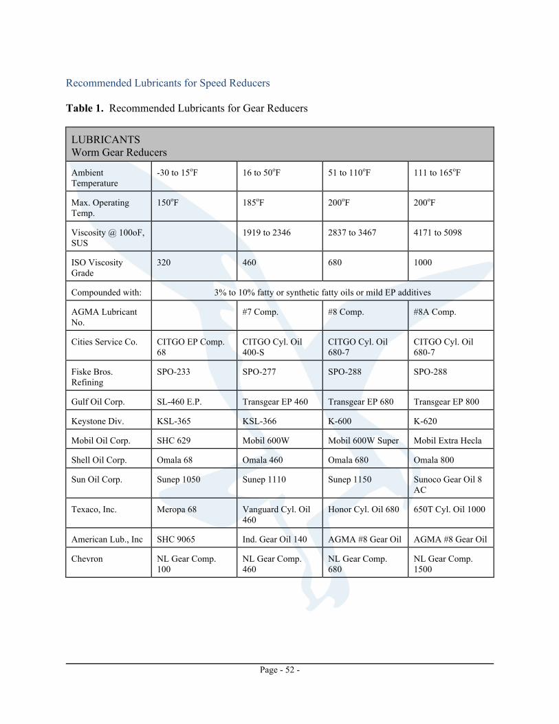
Page - 52 -
Recommended Lubricants for Speed Reducers Table 1. Recommended Lubricants for Gear Reducers LUBRICANTS Worm Gear Reducers Ambient Temperature
-30 to 15oF
16 to 50oF
51 to 110oF
111 to 165oF
Max. Operating Temp.
150oF
185oF
200oF
200oF
Viscosity @ 100oF, SUS
1919 to 2346
2837 to 3467
4171 to 5098
ISO Viscosity Grade
320
460
680
1000
Compounded with:
3% to 10% fatty or synthetic fatty oils or mild EP additives
AGMA Lubricant No.
#7 Comp.
#8 Comp.
#8A Comp.
Cities Service Co.
CITGO EP Comp. 68
CITGO Cyl. Oil 400-S
CITGO Cyl. Oil 680-7
CITGO Cyl. Oil 680-7
Fiske Bros. Refining
SPO-233
SPO-277
SPO-288
SPO-288
Gulf Oil Corp.
SL-460 E.P.
Transgear EP 460
Transgear EP 680
Transgear EP 800
Keystone Div.
KSL-365
KSL-366
K-600
K-620
Mobil Oil Corp.
SHC 629
Mobil 600W
Mobil 600W Super
Mobil Extra Hecla
Shell Oil Corp.
Omala 68
Omala 460
Omala 680
Omala 800
Sun Oil Corp.
Sunep 1050
Sunep 1110
Sunep 1150
Sunoco Gear Oil 8 AC
Texaco, Inc.
Meropa 68
Vanguard Cyl. Oil 460
Honor Cyl. Oil 680
650T Cyl. Oil 1000
American Lub., Inc
SHC 9065
Ind. Gear Oil 140
AGMA #8 Gear Oil
AGMA #8 Gear Oil
Chevron
NL Gear Comp. 100
NL Gear Comp. 460
NL Gear Comp. 680
NL Gear Comp. 1500

Page - 53 -
System Fans A definite time schedule for inspecting all rotating parts and accessories should be established. The frequency of inspection depends on the severity of operation and locality. Inspections might be weekly at first in order to set up the schedule. Alignment: Shaft must not be cocked in the bearings. Misalignment can cause overheating, wear to dust seals, bearing failure and unbalance. Hardware: Check tightness of all bolts and set screws. Lubrication: Check fan and motor bearings and add lubricant if necessary. Be careful not to over grease as this can damage bearings seals. Air flow: Make sure there are no obstructions to air flow in outlet or inlet ductwork. Bearings on high-speed fans tend to run hot. Therefore, do not replace a bearing because it feels hot to the touch. Place a pyrometer or contact thermometer against the pillow block and check the temperature. Ball pillow blocks can have total running temperatures of 165oF (74oC) before the cause of overheating be investigated. Wheel: Inspect wheel blades for accumulation of dust and dirt. Clean thoroughly with stream of water jet, compressed air or a wire brush. This will help prevent an unbalanced condition. If blades are aluminum, be careful not to damage them. Cover the bearings so water will not enter the pillow block. The wheel should be centered to prevent the blades from striking the housing. Make sure wheel is rotating in proper direction. Never run the fan at a higher speed than it was designed for unless you check with Osprey Corporation first. Fan Bearing Maintenance For most applications, a lithium base grease conforming to a NLGI grade 2 consistency should be used. This type of grease inhibits rust, is water resistant, and has a temperature range of -30oF to 200oF with intermittent highs of 250oF. Because oil lubricated bearings are usually used on high-speed or high temperature applications, refer to Osprey Corporation for the type of oil that should be used in your particular application. When greasing bearings it is important not to over grease. This is especially true if the bearings are equipped with extended grease lines and the bearings are not visible. In this case, more bearing failures occur due to over greasing than under greasing. It is best to give the bearings just one “shot” of grease periodically, when the bearings are not visible. When the bearings are visible, pump in grease until a small bead of grease forms around the bearing seals. It is very
Page - 54 -
important that fan bearing greasing take place while a fan is operating. Caution should be taken while working on and near rotating equipment to avoid personal injury. When oiling oil-lubricated bearings, oil should be poured into a cup at top of bearing until it reaches the overflow point at the lower oil cup. Motor Maintenance Lubricate motor bearings to the manufacturer’s recommendations. Lubrication recommendations are printed on tags attached to the motor. Should these tags be missing, the following will apply: A. Fractional Horsepower Sleeve Bearing Motors: Under normal operation at ordinary temperatures and clean surroundings, these motors will operate for three years without relubrication. Then lubricate annually with electric motor oil or SAE 10 oil. Under continuous operation at higher temperatures (but not to exceed 104oF ambient) relubricated annually. B. Fractional Horsepower Ball Bearing Motors: Under normal conditions, ball bearing motors will operate for five years without relubrication. Under continuous operation at higher temperatures (but not to exceed 104oF ambient) relubricated after one year. To relubricate where motors are not equipped with pressure fittings, disassemble motor and clean the bearings thoroughly. Repack each bearing one-third full with ball bearing grease.
-WARNING- Disconnect all power to motor before disassembling fan motor. C. Integral Horsepower Ball Bearing Motors: Motors having pipe plugs or grease fittings should be relubricated while warm and at standstill. Replace one pipe plug on each end shied with grease fitting. Remove other plug for grease relief. On low pressure, grease, run and lubricate until new grease appears at grease relief. Allow motor to run for ten minutes to expel excess grease. Replace pipe plugs. Motors not having pipe plugs or grease fittings can be relubricated by removing end shields, cleaning grease cavity and refilling three-fourths of circumference of cavity.
-WARNING- Disconnect all power and wait for fan blade to stop all motion before disassembling fan.

Page - 55 -
Table 1. Recommended relubrication intervals-general guide only.
HP Range
Standard Duty
8 Hr./Day
Sever Duty 24 Hr./Day Dirty-Dusty
Extreme Duty
Very Dirty High Ambient
Temps
1 1/2 - 7 1/2
5 Yrs.
3 Yrs.
9 Mos.
10 - 40
3 Yrs.
1 Yrs.
4 Mos.
50 - 150
1 Yrs.
9 Mos.
4 Mos. These ball bearing greases or their equivalents are satisfactory for ambients from -15oF. For motors:
Mobilplex EP#1 - Socony Mobil Oil Company Alvania Grease #2 - Shell Oil Company Andox B Grease - Esso Standard Oil Company Prestige #42 Grease - Sun Oil Company
V-Belt Drive Maintenance If belts squeal at start-up, they are too loose and should be tightened. Periodically, check belt and sheave wear, alignment, and tension. When belts show wear, replace all belts at once with a new matched set of belts. New belts will not work properly in conjunction with used belts due to difference in length. Belts and sheaves should be clean and free from grease. After installing new belts, check tension midway between sheaves. Belts should deflect about 1/64" per inch of span length with approximately 20 lb. force. Allow unit to run for 4-6 hours, then it will be necessary to re-tighten belts again because new belts tend to stretch initially. Basic Fire Protection Maintenance Sprinkler inspections should be made on a regular basis to detect possible damage, pipe leaks, or alteration. Automatic sprinklers should be replaced if they are painted, corroded, damaged, or if they have been in service over 50 years. A sprinkler that has been fused cannot be reassembled and reused. Replacement must be made with a sprinkler of the same size, type, and temperature rating. Refer to National Fire Protection Association Pamphlet 13A for further information.
-CAUTION- Always store unused sprinklers in a cool dry place. Never hang objects from sprinklers.

Page - 56 -
Fluorescent Lighting Do not perform any maintenance while Drum Filter is in operation. Lock out all electrical power before proceeding with any maintenance actions. Make sure all wiring is in good condition. Do not allow the Drum Filter to operate with worn and frayed wiring. If wiring becomes worn, replace it immediately. Check all wiring connections. Replace as necessary. Clean fiber build-up off of lighting as needed. Replace any light bulbs that have burned out. Auto-Lubricator (optional equipment) The only maintenance that is required of this system is: Make sure there is always silicone in the tank. Establish frequency of filling, as usage may vary. Both moisture and solids are removed by the filter/regulator. Drain whenever water level in sump reaches the lower baffle. Frequency depends on the condition of plant air. Install automatic drain if bowl draining is frequent. The filter element can be removed when necessary and should be washed in a solution of mild soap and water. Blow compressed air from inside the element outward after washing. When dry, re-install, making sure to replace all gaskets, each in its proper place. Inspect tubing run at least once a month to make sure that all connections are in good condition. To remove filter: 1. SHUT DOWN AIR LINE and exhaust secondary pressure. 2. Unscrew threaded bowl. 3. Disassemble cartridge assembly by unscrewing lower baffle. 4. Remove element for servicing. 5. Replace element and re-assemble.

Page - 57 -
Deflagration Vent Panels (optional equipment) Latches must have the explosion-venting feature tested periodically to insure that corrosion and/or build-up of foreign materials has not affected the mechanism. Under normal operation conditions, lubricate the bearing pin within the laminated cam with a light (SAE 10-30) oil every six months. Model No. 3H and 4H latches (heavy duty latches which have a locking handle on the top of the latch) should have the set screws in the handle tightened as needed. Relief latches are not recommended for exterior or corrosive applications. Regular steel latches (which are designed for interior use) will rust and could consequently freeze up so that the latch could become a lock and would possibly not open even if there were an explosion. Any regular steel latches being used in an exterior or corrosive environment should be replaced immediately. The following maintenance instructions should be followed while waiting for replacement parts.
-NOTE- Stainless steel or brass parts are available for latches mounted in exterior or corrosive environments
Latches in exterior or corrosive environments should be inspected and lubricated at frequent and regular intervals. The lubricating should be as follows: Apply heavy grease to the spring and laminated cam inside the latch upon original installation and regrease as necessary every 6-12 months. The crucial pivot joint, which is the bearing pin about which the laminated cam pivots, should be oiled with an SAE 30 to SAE 50 oil every two months, or more in the case of an extremely corrosive atmosphere. Inspection shall be done at least every 2 months. Drum Filter Sanitation Proper sanitation is necessary to provide a safe and effective work area for operating and maintenance personnel. Cleaning the drum filter and the area around the Drum Filter will decrease the possibility of accidents and machine failure.
-WARNING- All sanitation procedures should be performed only when the main electrical disconnect is off and locked out. DO NOT clean any part of the machine when the machine is running.
The area around the Drum Filter should be swept with enough frequency to prevent an accumulation of material that could cause hazards to operating personnel. The floor will become slick when a build-up of material occurs. Control of any equipment will be hindered by a build-up of foreign material. The Drum Filter and motor bearings should be inspected and cleaned as needed to prevent a build-up of material that would cause erratic action of the drum and motor. Be sure to clean any fluff or dirt from the ends of the shafts where the bearings are located to prevent the bearings seizing.

Page - 58 -
-NOTE- Normally, the only time the bearings would be contaminated would be from a tear or break in the filter media or failure of the seal. However, these items should be checked regularly.
Any bearing that is greased must have the excess grease wiped from the grease fitting and bearings outer surface. Grease and any dust or particulate will combine to form a very abrasive compound that can wear a bearing very quickly. Clean all fluff and dirt from the inside surfaces of the bearing enclosures with a vacuum or wiping.
-IMPORTANT- DO NOT use compressed air for sanitation purposes. This will only relocate the dust and fluff to other areas of the plant and will create health and safety hazards there. Use vacuum cleaners or wipe the surfaces.
The filter media and the seal should be inspected occasionally and any build-up of material removed. Inspect for tears and failure or excessive wear of the media or seal. If necessary repair or replace the media or seal. The vacuum nozzles do not clean the gap between each other, so this may have to be done manually. The whole Drum Filter, including the enclosure, should be wiped off periodically to help maintain the machine in good condition. Inspect all components of the drum filter and enclosure and auxiliary equipment as the cleaning is done to discover any item that needs attention and correct as required.
Page - 59 -
TROUBLESHOOTING GUIDE General Troubleshooting All trouble-shooting should be done in an orderly and logical step-by-step manner with only one procedure followed at a time. Trying more than one corrective measure at a time may in some instances mask the real cause of the problem. This trouble-shooting guide for the Osprey Drum Filter is designed to give assistance to plant maintenance personnel in the event of a failure of the drum filter.
-WARNING- Be sure all electrical disconnects have been turned off and the panel(s) locked out before any trouble-shooting, repair or service is performed.
The first step in determining the cause of a failure is to isolate the effects of the failure. The trouble-shooting guide will be helpful by giving some idea of abnormal conditions. The operators of the Drum Filter or the personnel that normally work around the filter will be a good source of information. This is because they will be able to recognize that the filter does not “sound right” or “looks funny”. They may not know why, but they will be able to describe unusual operation. The next step would be to go to the trouble-shooting guide and finding the problem you are encountering listed in the PROBLEM column. Common problems are listed in this column. The problem you have may not be listed exactly, but a closely related problem may be.
-IMPORTANT- DO NOT correct more than one item at a time since this could mask problems and only create a temporary repair that may lead to further damage that is more serious.
The last step would be to utilize the POSSIBLE CAUSE column and further isolate the problem. In all but one case, several possible causes are listed for the problems listed. Check again with the operators and maintenance personnel for the cause closest to what they suspect the problem to be. Lastly, check the possible solution column and determine if the solution listed with the cause you suspect to be the reason for the fault is the appropriate repair procedure. Proceed with repairs when the appropriate repairs are determined.
-NOTE- It may be necessary to check and recheck the trouble-shooting guide to determine the exact repair procedure. Do not make any hasty and unconfirmed decisions about the repair procedure. This could lead to damage that is more serious and personnel injury.

Page - 60 -
Finally, if you have followed the steps for determining and repairing the damage or fault and cannot isolate the cause satisfactorily, call Osprey for assistance. The majority of repairs can be made successfully by you after following the outline above. Be sure to exhaust all possibilities before calling Osprey to save you time and money.
PROBLEM
POSSIBLE CAUSE
POSSIBLE SOLUTION 1. Drive motor stops on overload. Drum jerks while rotating or pin shears. Chain pops or binds.
A. Seal is too tight. B. Seal not lubricated properly. C. Drum shifted toward plenum wall. D. Incorrect voltage on motor. E. Sheaves on motor or reducer switched or wring size. F. Drum is obstructed
A. Check size of the seal. B. Lubricate seal with silicone. C. Reset ½ " drum to plenum wall gap. Dimple drill and tighten set screws. D. Replace and/or rewire motor. E. Replace sheaves to achieve 1 RPM on drum. F. Remove obstruction and repair as necessary.
2. Excessive sprocket or chain wear.
A. Poor sprocket alignment.
A. Align sprockets and tighten.
3. Drum shifts against plenum wall, seal gap uneven.
A. Excessive pressure drop across drum. B. Drum cage sections loose on shaft, shaft loose in bearings. C. Bearings moving.
A. Check media condition, repair or replace as needed. B. Reset ½ " drum to plenum wall gap. Dimple drill and tighten set screws C. Align and true wall and replace any missing anchor or enclosure fastening bolts. D. Shift and/or shim bearings then fasten securely.
4. Nozzles, manifold, or duct clogs.
A. Vacuum fan not adequate, rotating too slow or backwards. B. Flex or rigid duct has bends, kinks, holes, burrs, etc. C. Nozzle slot too small for type or amount of waste. D. Nozzle too close to media. E. Back pressure from final collection device or dust.
A. Check vacuum fan duty specifications, speed and rotation then correct as necessary. B. Repair, seal, or replace as necessary. C. Replace with larger slot nozzle. D. Adjust and secure. E. Replace and/or repair as necessary.
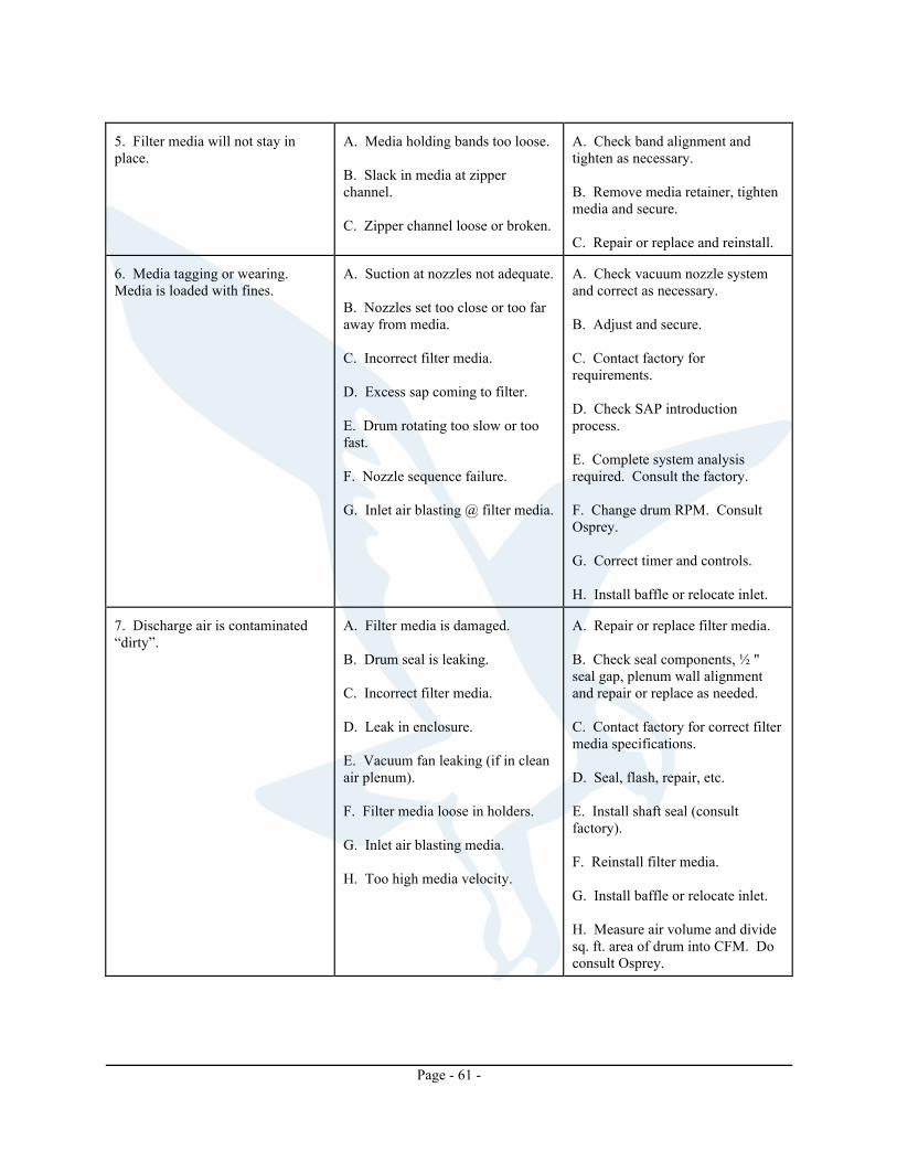
Page - 61 -
5. Filter media will not stay in place.
A. Media holding bands too loose. B. Slack in media at zipper channel. C. Zipper channel loose or broken.
A. Check band alignment and tighten as necessary. B. Remove media retainer, tighten media and secure. C. Repair or replace and reinstall.
6. Media tagging or wearing. Media is loaded with fines.
A. Suction at nozzles not adequate. B. Nozzles set too close or too far away from media. C. Incorrect filter media. D. Excess sap coming to filter. E. Drum rotating too slow or too fast. F. Nozzle sequence failure. G. Inlet air blasting @ filter media.
A. Check vacuum nozzle system and correct as necessary. B. Adjust and secure. C. Contact factory for requirements. D. Check SAP introduction process. E. Complete system analysis required. Consult the factory. F. Change drum RPM. Consult Osprey. G. Correct timer and controls. H. Install baffle or relocate inlet.
7. Discharge air is contaminated “dirty”.
A. Filter media is damaged. B. Drum seal is leaking. C. Incorrect filter media. D. Leak in enclosure. E. Vacuum fan leaking (if in clean air plenum). F. Filter media loose in holders. G. Inlet air blasting media. H. Too high media velocity.
A. Repair or replace filter media. B. Check seal components, ½ " seal gap, plenum wall alignment and repair or replace as needed. C. Contact factory for correct filter media specifications. D. Seal, flash, repair, etc. E. Install shaft seal (consult factory). F. Reinstall filter media. G. Install baffle or relocate inlet. H. Measure air volume and divide sq. ft. area of drum into CFM. Do consult Osprey.
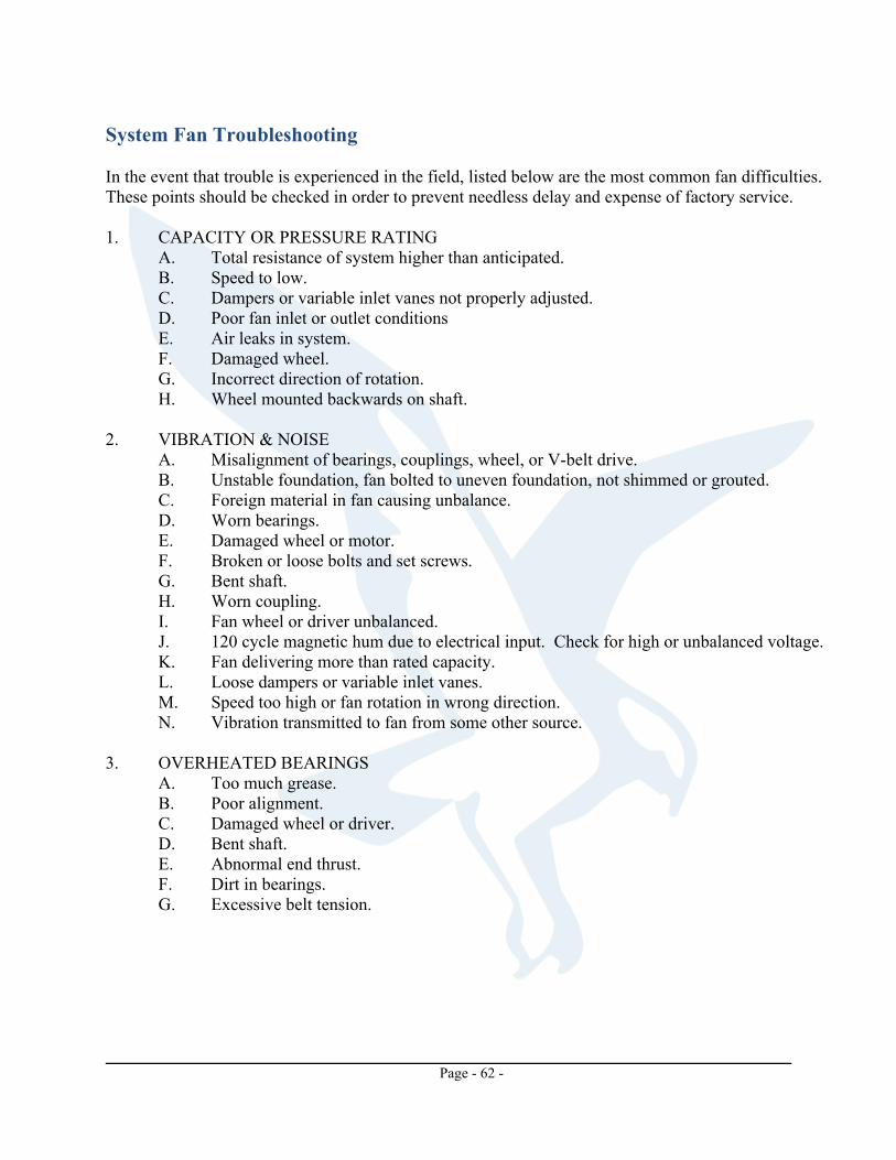
Page - 62 -
System Fan Troubleshooting In the event that trouble is experienced in the field, listed below are the most common fan difficulties. These points should be checked in order to prevent needless delay and expense of factory service. 1. CAPACITY OR PRESSURE RATING
A. Total resistance of system higher than anticipated. B. Speed to low. C. Dampers or variable inlet vanes not properly adjusted. D. Poor fan inlet or outlet conditions E. Air leaks in system. F. Damaged wheel. G. Incorrect direction of rotation. H. Wheel mounted backwards on shaft.
2. VIBRATION & NOISE
A. Misalignment of bearings, couplings, wheel, or V-belt drive. B. Unstable foundation, fan bolted to uneven foundation, not shimmed or grouted. C. Foreign material in fan causing unbalance. D. Worn bearings. E. Damaged wheel or motor. F. Broken or loose bolts and set screws. G. Bent shaft. H. Worn coupling. I. Fan wheel or driver unbalanced. J. 120 cycle magnetic hum due to electrical input. Check for high or unbalanced voltage. K. Fan delivering more than rated capacity. L. Loose dampers or variable inlet vanes. M. Speed too high or fan rotation in wrong direction. N. Vibration transmitted to fan from some other source.
3. OVERHEATED BEARINGS
A. Too much grease. B. Poor alignment. C. Damaged wheel or driver. D. Bent shaft. E. Abnormal end thrust. F. Dirt in bearings. G. Excessive belt tension.
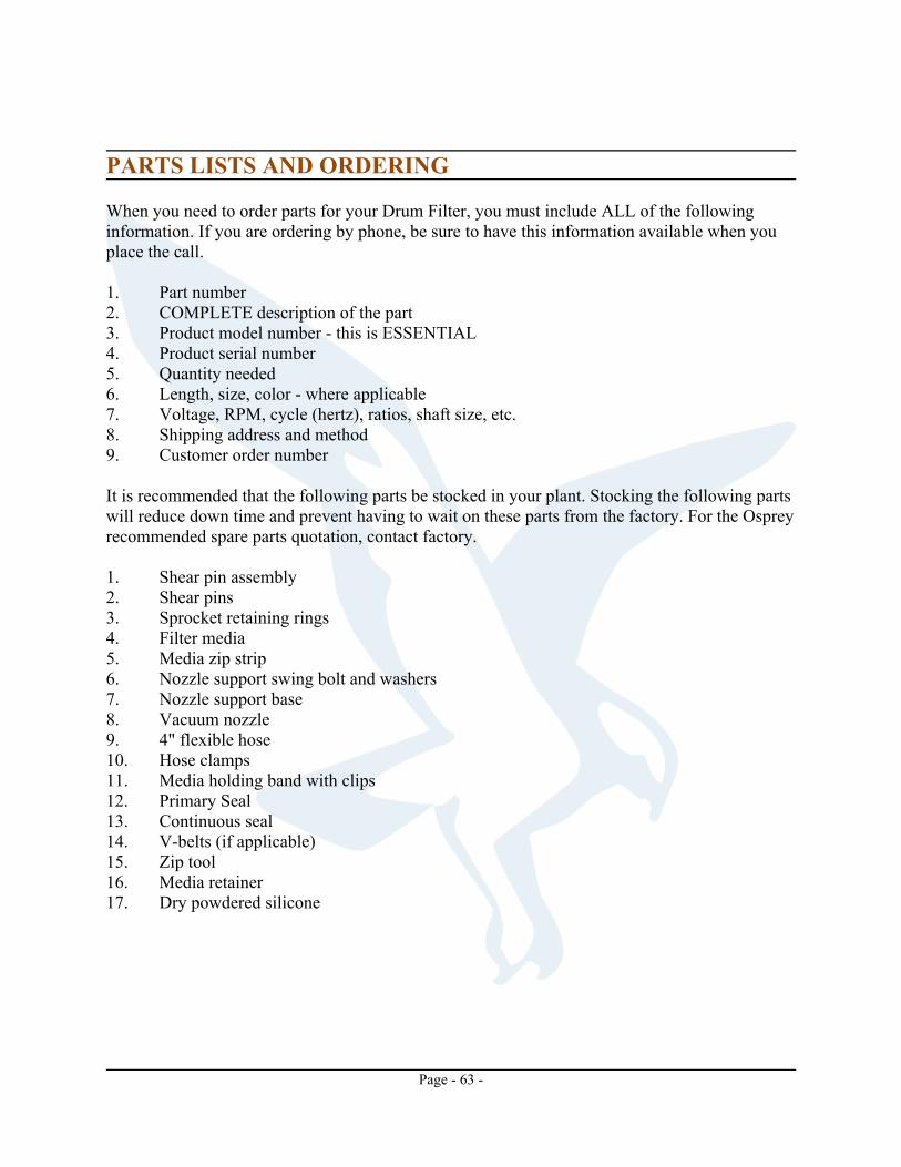
Page - 63 -
PARTS LISTS AND ORDERING When you need to order parts for your Drum Filter, you must include ALL of the following information. If you are ordering by phone, be sure to have this information available when you place the call. 1. Part number 2. COMPLETE description of the part 3. Product model number - this is ESSENTIAL 4. Product serial number 5. Quantity needed 6. Length, size, color - where applicable 7. Voltage, RPM, cycle (hertz), ratios, shaft size, etc. 8. Shipping address and method 9. Customer order number It is recommended that the following parts be stocked in your plant. Stocking the following parts will reduce down time and prevent having to wait on these parts from the factory. For the Osprey recommended spare parts quotation, contact factory. 1. Shear pin assembly 2. Shear pins 3. Sprocket retaining rings 4. Filter media 5. Media zip strip 6. Nozzle support swing bolt and washers 7. Nozzle support base 8. Vacuum nozzle 9. 4" flexible hose 10. Hose clamps 11. Media holding band with clips 12. Primary Seal 13. Continuous seal 14. V-belts (if applicable) 15. Zip tool 16. Media retainer 17. Dry powdered silicone