Drop Tower Design
70
Design of a Cost Effective Drop Tower for Impact Testing of Aerospace Materials Major Qualifying Project Submitted to the Faculty of WORCESTER POLYTECHNIC INSTITUTE In partial fulfillment of the requirements for the Degree of Bachelor of Science Report Submitted Project Advisors: Maria Chierichetti Anthony Linn Report Submitted by: Shawn Ferrini, Latthapol Khachonkitkosol, Michael Strauss 3/9/2015
Transcript of Drop Tower Design

Design of a Cost Effective Drop Tower for Impact Testing of Aerospace Materials
Major Qualifying Project Submitted to the Faculty of
WORCESTER POLYTECHNIC INSTITUTE In partial fulfillment of the requirements for the
Degree of Bachelor of Science
Report Submitted Project Advisors:
Maria Chierichetti
Anthony Linn
Report Submitted by:
Shawn Ferrini, Latthapol Khachonkitkosol, Michael Strauss
3/9/2015

1
Abstract
The unique challenges presented by the high performance and stringent safety demands of the
aerospace engineering field require advanced materials. These materials are constantly being developed
and refined, and a thorough knowledge of their properties and behavior is necessary before they can be
put to use. Energy absorption is an important mechanical property that is most commonly evaluated by
conducting impact tests. This project has developed a low-cost, reliable, guided drop tower for impact
testing of novel aerospace materials. The project team has produced a complete design along with a
user manual and bill of materials. It is anticipated that the final design will used to fabricate and
assemble a drop tower for future research.

2
Acknowledgements
We would like to thank the following individuals and organizations for the support they provided
our team. Without their tireless help and support, our project would not have been possible.
Professor Maria Chierichetti for her advice and insight in the early stages of this project.
Professor Anthony Linn for his attention to detail and design experience.
Russ Lang of the Civil Engineering department for his help in planning the concrete design.
Professor Don Pellegrino of the Civil Engineering department for showing us the drop towers in
his lab and advising us in specific improvements to incorporate.
Kevin Arruda who provided invaluable manufacturing advice.
Worcester Polytechnic Institute for presenting us with this opportunity.

3
Authorship
Title Page ............................................................................................................................................. Strauss
Abstract ............................................................................................................................................... Strauss
Acknowledgements ............................................................................................................................. Strauss
Authorship .......................................................................................................................................... Strauss
Chapter 1: Introduction ...................................................................................................................... Strauss
Chapter 2: Background Research ............................................................... Khachonkitkosol, Ferrini, Strauss
Section 2.1, 2.2 .................................................................................................................................. Ferrini
Section 2.3 ......................................................................................................................... Khachonkitkosol
Section 2.4 ....................................................................................................................................... Strauss
Chapter 3: Design Process ......................................................................... Khachonkitkosol, Ferrini, Strauss
Section 3.1 ........................................................................................................................ Khachonkitkosol
Section 3.2, 3.4 .................................................................................................................................. Ferrini
Section 3.3, 3.5, 3.6,3.7 ................................................................................................................... Strauss
Chapter 4: Conclusions and Recommendations .................................................................. Khachonkitkosol
Appendices ................................................................................................. Khachonkitkosol, Ferrini, Strauss
All team members participated in the revision and editing of all sections.

4
Table of Contents
Abstract ......................................................................................................................................................... 1
Acknowledgements ....................................................................................................................................... 2
Table of Contents .......................................................................................................................................... 4
Table of Figures ............................................................................................................................................. 5
Table of Tables .............................................................................................................................................. 6
1. Introduction .......................................................................................................................................... 7
2. Background Research ............................................................................................................................ 9
2.1 Introduction to types of Drop Tests .............................................................................................. 9
2.2 ASTM Standards .......................................................................................................................... 10
2.3 Commercially Available Drop Towers ......................................................................................... 11
2.4 Civil Lab Drop Towers .................................................................................................................. 14
3. Design Process .................................................................................................................................... 16
3.1 Important Design Decisions and Tower Parameters .................................................................. 16
3.2 CAD Modeling ............................................................................................................................. 18
3.3 Base Design ................................................................................................................................. 18
3.4 Sample Mount Design ................................................................................................................. 23
3.5 Drop Platen Design ..................................................................................................................... 25
3.6 Quick Release Design .................................................................................................................. 28
3.7 Safety Considerations ................................................................................................................. 29
3.8 Instrumentation ............................................................................................................................. 30
5. Conclusions and Recommendations for Future Work ........................................................................ 33
6. References .......................................................................................................................................... 34
Appendix A: CAD Drawings ......................................................................................................................... 35
Appendix B: List of Materials ...................................................................................................................... 61
Appendix C: User Manual ........................................................................................................................... 62
Appendix D: Quick Release Latch Mechanism Diagram ............................................................................. 66

5
Table of Figures Figure 1 Previous MQP Drop Tower ........................................................................................................... 14
Figure 2 Close View of Drop Platen ............................................................................................................. 15
Figure 3 Steel Plate Base ............................................................................................................................. 19
Figure 4 Rubber Dock Bumber .................................................................................................................... 20
Figure 5: Box filled with concrete ............................................................................................................... 21
Figure 6 Third Iteration Base Assembly Design .......................................................................................... 22
Figure 7 Final Base Design ........................................................................................................................... 23
Figure 8 Initial Sample Mounting ................................................................................................................ 24
Figure 9: Finalized sample mounting design ............................................................................................... 25
Figure 10: Preliminary Drop Platen Designs ............................................................................................... 26
Figure 11: Optimized two guide rail design ................................................................................................ 27
Figure 12 Final Drop Platen Design ............................................................................................................. 27
Figure 13 Interlocking test weights ............................................................................................................. 28
Figure 14 Full Tower .................................................................................................................................... 35
Figure 15 Full Tower Assembly Drawing ..................................................................................................... 36
Figure 16 Tower Base .................................................................................................................................. 37
Figure 17 Mounts for Leveling Screws ........................................................................................................ 38
Figure 18 Caster Mount Cross Beams ......................................................................................................... 39
Figure 19 Caster mounting Plate ................................................................................................................ 40
Figure 20 Leveling Screws Mounting Plate ................................................................................................. 41
Figure 21 Base Top Plate ............................................................................................................................. 42
Figure 22 Base Short Side............................................................................................................................ 43
Figure 23 Base Long Side............................................................................................................................. 44
Figure 24 Tower Base Assembly ................................................................................................................. 45
Figure 25 Drop Platen with Penetrator ....................................................................................................... 46
Figure 26 Latch Mechanism Hook ............................................................................................................... 47
Figure 27 Penetrator Collar ......................................................................................................................... 48
Figure 28 Latch Mechanism Platen ............................................................................................................. 49
Figure 29 Quick Release Mechanism Assembly .......................................................................................... 50
Figure 30 Half Inch Penetrator .................................................................................................................... 51
Figure 31 Three Quarter Inch Penetrator ................................................................................................... 52
Figure 32 One Inch Impactor ...................................................................................................................... 53
Figure 33 Drop Platen Drawing ................................................................................................................... 54
Figure 34 Quick Release Assembly Model .................................................................................................. 55
Figure 35 Sample Mount ............................................................................................................................. 56
Figure 36 Sample Mounting Platform ......................................................................................................... 57
Figure 37 Mounting Plate Standoff ............................................................................................................. 58
Figure 38 Sample Mounting Platform Assembly ........................................................................................ 59
Figure 39 Top Assembly Drawing ................................................................................................................ 60
Figure 40 Top Assembly Model ................................................................................................................... 60

6
Table of Tables Table 1 Low to Medium Energy Drop Towers ............................................................................................. 12
Table 2 Medium Impact Energy Drop Towers ............................................................................................ 13
Table 3 Sample Materials and Predicted Peak Acceleration ...................................................................... 32

7
1. Introduction
The aerospace engineering field is driven by high performance. Almost every component of an
air or space craft is required to perform under more extreme conditions than any other. To handle the
stresses, temperatures, and other conditions faced these parts must be expertly engineered,
meticulously manufactured, and made from high quality materials.
To meet the stringent performance and safety demands of the aerospace industry new
materials are constantly being developed. A thorough knowledge of the mechanical properties of these
new materials is necessary to predict their behavior when they are used for their intended purpose.
There are numerous tests that can be performed to determine properties such as hardness, yield
strength, and energy absorption.
The most common method for testing energy absorption is by conducting impact tests. Drop
towers have been developed for reliable, repeatable impact tests. There are several drop towers
commercially available, however these models are very expensive and in many cases are unsuitable for
aerospace materials testing based upon their range of drop energy.
WPI currently has two drop towers in the civil engineering labs; however neither is suitable for
aerospace materials use. Both towers are used for testing structural components in civil engineering
applications. This project focuses on designing a cost effective and reliable drop tower tailored
specifically for aerospace applications.
The initial parameters and goals for this design were developed by the project team. Completion
of this project required the delivery of a conceptual design of a guided drop tower with a variable
impact mass capable of testing samples of sizes ranging from 4X4 in up to 10X10 in. The team worked to
expand these ideas into a complete design by researching common aerospace materials, commercially

8
available drop towers, as well as relevant ASTM standards for impact testing. This report summarizes
the background research performed, the design process, and the conclusions and recommendations for
future work.

9
2. Background Research
2.1 Introduction to types of Drop Tests
Since 1898, ASTM international, formerly American Society for Testing and Materials, has been
developing globally recognized voluntary consensus standards for a variety of different processes in an
effort to “improve product quality, enhance safety, facilitate market access and trade, and build
consumer confidence” [1]. Over the years standards have been developed for many different areas,
including impact tests using drop towers. These standards explore different testing setups for various
applications such as football helmets, shoes, and fencing surfaces, as well as many other materials.
Within the world of impact tests there are two main designations based on setup, the
Charpy/Izod Impact Tests and the Gardner Impact Test. In Charpy/Izod Impact Tests, the dropping
mechanism consists of a weighted pendulum which is brought to a pre-determined height and dropped.
The striker at the end of the pendulum swings towards a sample to break it and the energy absorbed by
the sample is measured. In the Charpy Impact test the sample is mounted horizontally with either a U-
notch or a V-notch oriented away from the striker, providing reliable collision data. [2] Whereas the Izod
Impact test orients the sample vertically with the notch facing the striker on the pendulum, evaluating
the quality and hardness of the materials. Both the Charpy and Izod tests are limited to non-compound
materials due to their inconsistent failure modes. [2]
The second major type of drop test, and the one that is most similar to the purpose designated
for this project, is the Gardner Impact test. This type of impact drop test is characterized by the vertical
dropping of a variable mass impactor, striking a sample at the bottom. The energy of the impact is
determined as a function of the drop height and drop mass. In this form of drop test the sample can vary
in size, shape, and orientation, ranging from the rubber used in shoes to the plastic used in football
helmets. The test can be conducted for normal or oblique impacts and, in some instances, the test
10
specimen itself can be dropped. In these tests, the energy absorption of the sample is measured by
calculating the area under the stress strain curve. The force of impact on the specimen can also be
determined using accelerometer data and the drop mass. [2]While both subsets of impact tests have
wide use in the manufacturing and processing world, the current project focuses solely on Gardner type
impact tests. The next section describes relevant ASTM standards.
2.2 ASTM Standards
The first relevant standard explored was ASTM D1596: Standard test Method for Dynamic Shock
Cushioning Characteristics of Packaging Material. The similarity of this standard to the current design
problem allowed for many important design characteristics to be determined: [3]
The reaction mass, or the entirety of the structure not including the drop platen, must
be at least fifty times the mass of the drop platen so that less than two percent of the
impact energy is absorbed by the structure instead of the sample
The use of three test specimens per material and proper conditioning of materials is also
stressed in the standard. The source material should be tested at various parameters,
such as temperature, humidity, thickness, etc., in order to obtain a more complete
analysis of its properties.
D3763 Standard Test Method for High Speed Puncture Properties of Plastics Using Load and
Displacement Sensors is also relevant. This standard helps specify a baseline velocity of the drop platen
at impact that allows the definition of the maximum drop height. [4]
F429 Standard Test Method for Shock-Attenuation Characteristics of Protective Headgear for
Football is another ASTM standard involving Gardner type drop tests that was scrutinized during the
literature research. While the application is very different from the scope of this project, the standard
provides new knowledge on sample choice and conditioning. Before the actual testing, three initial dry

11
runs of the tower should be performed to check the functionality of the instruments. Then after the
actual tests three more dry runs should be performed to ensure that the instrumentation functioned
properly during testing and that the collected data is reliable Moreover, F429 requires that each sample
be conditioned for a minimum of four hours before testing and that the test be conducted within five
minutes upon removal from the conditioning environment to limit the amount of un-conditioning within
the sample. For every five minutes out of the conditioning environment, the sample should be placed
back in the conditioning environment for fifteen minutes to reacclimatize itself to the desired
conditions. These propositions ensure that all data acquisition is working optimally and that testing
conditions remain consistent to reduce the amount of error. [5]
2.3 Commercially Available Drop Towers
There are many commercially available towers on the market. One of the purposes of this
project is to design a more cost effective drop tower. The major brands that produce drop towers are
Instron, Imatek, and Zwick/Roell. These brands offer a wide range of towers with different energy
ranges for different types of materials. Medium energy towers, used for testing aerospace materials,
were referenced when making initial design choices. Primarily, the parameters investigated were impact
velocity, drop weight, and drop height, all of which contribute to impact energy.
High energy towers can generate up to 100KJ of impact energy and are used to test high
strength materials. The energy range and size of these towers are well beyond the scope of test
materials used in the project; their parameters were not incorporated into the initial design.

12
Data type Instron CEAST 9340 Instron CEAST 9350 Zwick/Roell HIT230F
Energy (J) 0.30 – 405 0.59 – 757 Up to 230
Impact velocity (m/s) 0.77 - 4.65 0.77 – 4.65 Up to 4.4
Drop height (m) 0.03 – 1.1 0.03 – 1.1 0.11 – 1
Drop weight (kg)
Machine weight (kg)
1 – 37.5
340
2 – 70
550
23.5
400
Test area dimensions (m)
Overall dimensions (m)
0.49 x 0.45 x 0.565
0.985 x 0.61 x 2.62
0.7 x 0.72 x 0.55
1.015 x 0.866 x 2.7
Not specified
1 x 0.6 x 2.6
Specimens note Suitable for tensile
impact tests on plates,
and Charpy tests.
Versatile. Can test from
composites to finished
products.
For plastic testing.
Table 1 Low to Medium Energy Drop Towers

13
Data type Zwick/Roell P550 Imatek IM10T - 20 Imatek IM1-P
Energy (J) 340 – 550 2.5 – 588 24 – 118
Impact velocity (m/s) Up to 4.4 1 – 6.26 2.2 – 4.85
Drop height (m) Up to o1 0.05 – 2 0.25 – 1.2
Drop weight (kg)
Machine weigh (kg)
34 – 56
2800
8 – 30
2800
10
800
Test area dimensions (m)
Overall dimensions (m)
0.05 x 0.13 x 0.019
1.36 x 0.84 x 2.7
0.7 x 0.72 x 0.55
1.42 x 0.76 x 4.5
Not specified
1 x 0.8 x 3.0
Specimens note Used for
composite/plastic
plaque and film
testing.
Table 2 Medium Impact Energy Drop Towers
The initial design for this project was based on the energy range of the Imatek IM1-P which is
mainly used for testing composite and plastic plaques. It should be noted that these commercially
available towers have built-in velocity and drop height simulation systems to produce a larger range of
impact energy. In order to compensate for lack of such systems, the initial design includes a drop height
greater than that of IM1-P. The resultant ideal velocity and impact energy will be discussed in section
3.8.

14
2.4 Civil Lab Drop Towers
WPI currently has two drop-towers located in the Civil Engineering department. One of them is a
commercial tower produced by Instron, and the other is a tower designed and built by a previous Civil
Engineering MQP team. These towers are designed to be used for testing Civil Engineering structural
components and are unsuitable for testing aerospace materials. The project team also spoke with
technicians in the lab and received feedback on how to optimize drop tower functionality based on their
experience. Their feedback can be summarized as the following:
Reduce friction to achieve closer to ideal velocity
Design simplified drop platen
Create more rigid drop platen and impact surface
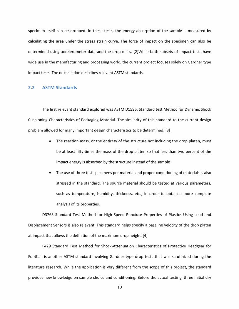
The drop tower built by the previous MQP as well as a close up of the drop platen used are pictured
below in figures 1 and 2.
Figure 1 Previous MQP Drop Tower
15
As seen in fig. 2 the drop platen used is a very complex design, which was developed separately from the
main structure. It is clamped around the four support columns which were greased before each test in
an attempt to reduce friction. Despite the grease, this assembly still created large amounts of friction
and caused the mass to slow from its theoretical maximum velocity. Additionally the complexity and
number of struts led to issues with rigidity required maintenance between each test to retighten all the
connections. This projects conceptual design will focus on reducing friction, increasing rigidity by
simplifying the drop platen. It is hoped that this will increase accuracy of data and reduce the time
between tests.
Figure 2 Close View of Drop Platen

16
3. Design Process
The evolution of this project’s design was not a single step process and went through several
major design iterations all designs will be introduced in this section and then elaborated upon.
3.1 Important Design Decisions and Tower Parameters
The following are important initial design decisions based on ASTM standards, simple
calculations, specifications of commercial drop towers, and discussions with experts:
Dimensioning: Dimensions of the base, guide rail spacing and drop platen were determined
based upon suggestions found in relevant ASTM standards as well as practical limitations. The base was
sized to fit through doorways for ease of transportation, which constrained the dimensions of other
components.
Maximum drop weight of 10 kg and reaction mass of 500 kg: According to ASTM D1596, the
reaction mass, defined as the mass consisting of the impact surface and any other rigidly attached mass
that reacts in an opposing manner to the forces produced during the impact of the dropping platen on
the impact surface, must be at least 50 times the drop mass.. Taking into consideration the load that the
floor in the Aerospace Engineering Lab would be subjected to and the need to move the tower in the
future, a maximum mass of 500 kg (1102 lbs.) was chosen. This means that the design can have up to 10
kg (22.1 lbs.) of drop weight, which is the same as that of the commercial model IM1-P. In order to
achieve the weight of 500 kg in a cost-effective manner, concrete will be used in the construction of the
base
Maximum drop height of 1.5 meters (4.9 feet): In order to generate an ideal impact energy in
the same range as IM1-P without using any height or velocity augmentation system, such as pneumatics
or springs, the total tower height was chosen at 2 meters (6.6 feet) – which can easily fit in the lab – and
maximum drop height of 1.5 meters were used. This height is advantageous because it will easily fit in

17
the lab and deliver drop energy on par with the commercial drop towers. Using the kinetic energy
equation, the ideal velocity and ideal maximum impact energy in ideal free-fall were calculated:
𝑣 = √2𝑔ℎ
𝐾𝐸 =1
2𝑚𝑣2
Ideal velocity of 5.42 m/s (17.8 ft./s) and maximum impact energy of 146.9 J (108.3 ft.*lbf.) were
obtained. Due to the low velocity, air drag on the platen becomes negligible. Moreover, every effort will
be made to reduce friction to a minimum including the use of linear bearings on polished guide rails.
Four guide rails with ball bearings: The tower will have four guide rails as opposed to two
providing stability while reducing the chance for the drop platen to hitch. Linear ball bearings will also
be used where the drop platen comes in contact with the guide rails to reduce friction. Depending on
how the bearings are clamped, the rolling resistance of the bearings can be negligible:
𝐹 = 𝐶𝑟𝑟 ∗ 𝑁
Where Crr is the coefficient of rolling friction and N is the normal force. Typical values for rolling
resistance coefficient can vary from between 0.001 to 0.0024, for railroad steel wheel and steel rail, to
between 0.3, for an ordinary car tire on sand.

18
After these major decisions were made, the first incarnation of the CAD model was created
beginning with the drop platen and the base. Included in the initial design were two guide rails used to
guide a drop platen which rode on linear bearings, a sample mounting system which instituted an
adjustment system featuring guided threaded rods and tall platforms, a base made entirely of steel, and
a top plate also made entirely of steel.
3.2 CAD Modeling
The original design concept would go through major changes following the group’s meeting with
a manufacturing expert. Changes were made to simplify designs, decrease fabrication time, reduce
costs, and better overall performance. The first piece of the design changed was the base, which was
resized to accommodate the average door frame around campus, since the tower would eventually
need to be transported. The base was also changed from a solid block of concrete to a box made of steel
plate filled with concrete for additional weight. Using the concrete cuts down on cost and the steel
makes the structure of the tower easier to mount. It was also suggested that the guide rails and drop
platen design be rethought to prevent the drop platen hitching. The original design of the sample
mounting area was deemed too difficult to manufacture as well and new designs were developed to
simplify fabrication and increase sturdiness. Finally, the top plate was replaced with a structure made
from aluminum x-bar extrusions for easier manufacture, reduced cost, and streamlined integration into
the final structure.
3.3 Base Design
The design for the base of the drop tower underwent several iterations before being finalized.
The rest of the tower is designed and dimensioned off the base making it a critical piece in the design.
ASTM standard D 1596 requires that the reaction mass be 50 times greater than the mass of the drop
platen. In order to comply with this standard the tower is designed to have a base weighing at least
19
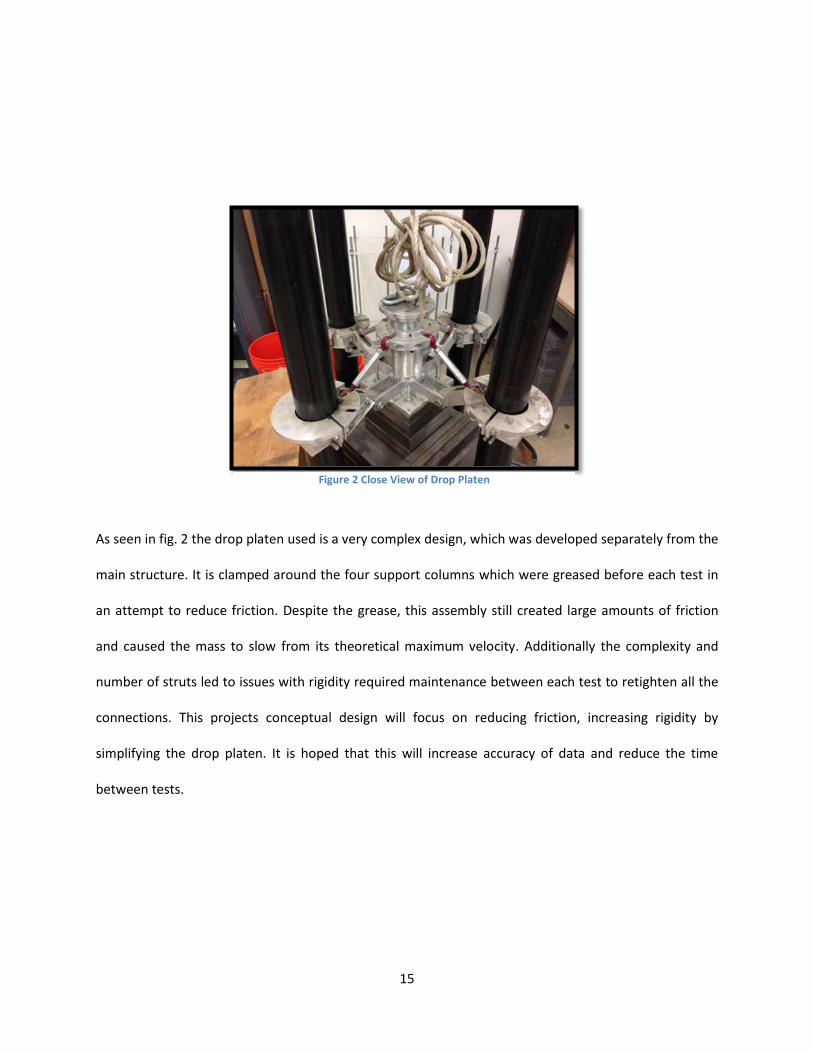
385.6 kg (850lbs); concentrating the majority of the weight in the base makes the tower more stable.
The base must also be able to fit through doorways and be transported between different labs and
buildings. There must also be a method of dampening the impact transferred to the floor of the lab.
Figure 3 Steel Plate Base
The first iteration was a 1m X 1m X .04 m (39.4 in X 39.4 in X 1.5 in) steel plate. In order to lessen
the impact on the lab floor rubber loading dock bumpers were designed to be used as feet underneath
the steel plate. These rubber bumpers are typically used for loading docks to protect semi-truck trailers
from damage. This design met the requirements for weight but was ultimately rejected. The steel plate
was far too expensive, costing approximately $1200. This made this iteration of the design infeasible for
use in this project.

20
In order to cut down on cost the project team decided to use concrete to attain the necessary
mass. Premixed concrete is available for $3.75 per 80 lbs. This resulted in a significant cost savings,
approximately 95%. Pursuing this design created a host of other problems however. Russ Lang, the
supervisor for the civil engineering labs at WPI, was a consultant with the project team in concrete
design. Pouring a base of this size would require rebar reinforcements and a very sturdy mold. Because
concrete cannot be machined like a steel plate can, precisely attaching the vertical components of the
rest of the tower would become very difficult. To counteract this problem the design included steel
square tubes sunk into the concrete that would act as sleeves for the vertical risers. While concrete is
incredibly strong in compression it is poor when a tensile or bending load is applied. Even small non-
axial forces applied to the tube sleeves could cause the concrete to crack compromising the structure of
Figure 4 Rubber Dock Bumper
21
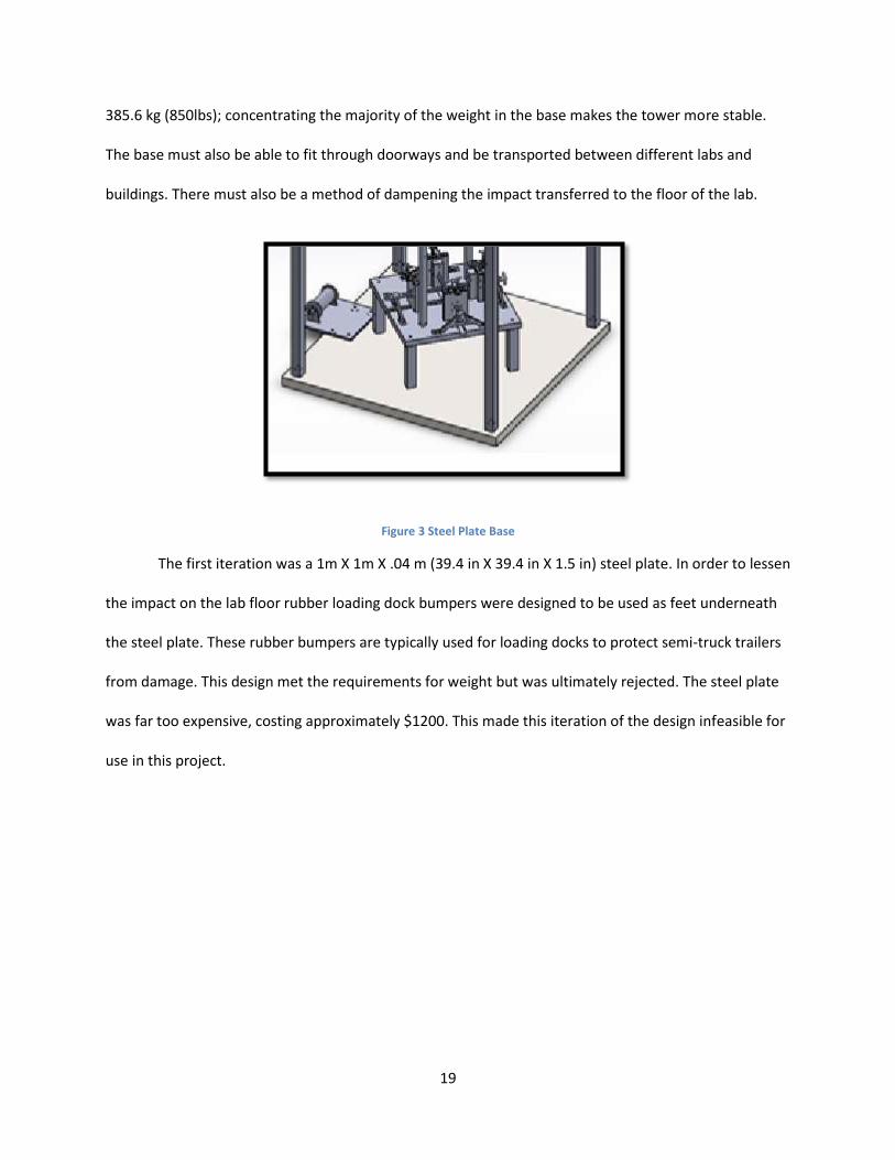
the tower as a whole. Additionally mounting the dock bumper feet would be nearly impossible due to
the size and mass of the slab.
Figure 5: Box filled with concrete
A hybrid design was developed for the third iteration. To provide support to the concrete a
thinner steel plate was placed on top of the concrete slab. This cut down on cost from the first iteration
and reduced the load on the concrete from the second iteration. It also added an easier place to anchor
the other components on the top of the base. This still left the issue of mounting the dock bumpers
below the concrete, as well as issues of concrete cracking during transport. Creating the frame for the
concrete mold and attaching the metal sheet over the top still needed to be addressed. The dimensions
of the base were also changed at this stage to accommodate transportation through doorways and
between labs.
22
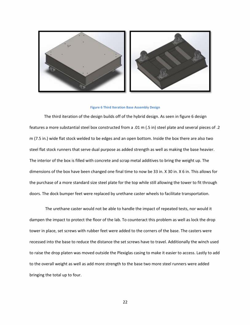
Figure 6 Third Iteration Base Assembly Design
The third iteration of the design builds off of the hybrid design. As seen in figure 6 design
features a more substantial steel box constructed from a .01 m (.5 in) steel plate and several pieces of .2
m (7.5 in.) wide flat stock welded to be edges and an open bottom. Inside the box there are also two
steel flat stock runners that serve dual purpose as added strength as well as making the base heavier.
The interior of the box is filled with concrete and scrap metal additives to bring the weight up. The
dimensions of the box have been changed one final time to now be 33 in. X 30 in. X 6 in. This allows for
the purchase of a more standard size steel plate for the top while still allowing the tower to fit through
doors. The dock bumper feet were replaced by urethane caster wheels to facilitate transportation.
The urethane caster would not be able to handle the impact of repeated tests, nor would it
dampen the impact to protect the floor of the lab. To counteract this problem as well as lock the drop
tower in place, set screws with rubber feet were added to the corners of the base. The casters were
recessed into the base to reduce the distance the set screws have to travel. Additionally the winch used
to raise the drop platen was moved outside the Plexiglas casing to make it easier to access. Lastly to add
to the overall weight as well as add more strength to the base two more steel runners were added
bringing the total up to four.

23
This final base design fits all the design parameters laid out for this project. It will be relatively
easy to transport, and with the concrete and scrap additives will weigh 850 lbs. The steel top also
provides a convenient and relatively easy place to secure the other components of the drop tower.
3.4 Sample Mount Design
One of the design requirements given to the team at the beginning of the project was the ability
to accommodate samples of various sizes. This led to a preliminary design including four sample mounts
with a height of 5 in that included a .375 in indentation at the top creating a resting area for the sample
to sit in. The four sample mounts would be adjusted by tightening threaded rods that ran through the
center of the vertical face of the mount. The threaded rods were further supported by an a-frame
structure located behind the mount. The sample mounts would follow a grooved track on the platform
which would include inch demarcations for accurate adjustment. Once the sample was seated in the
Figure 7 Final Base Design
24
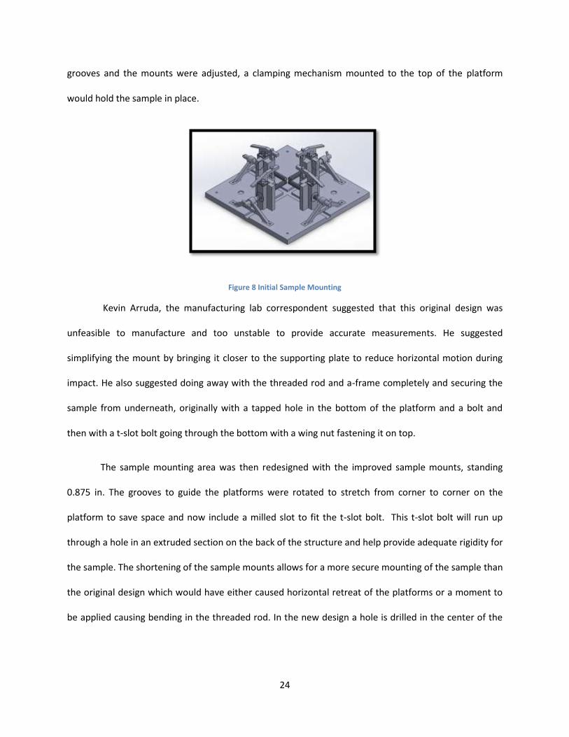
grooves and the mounts were adjusted, a clamping mechanism mounted to the top of the platform
would hold the sample in place.
Figure 8 Initial Sample Mounting
Kevin Arruda, the manufacturing lab correspondent suggested that this original design was
unfeasible to manufacture and too unstable to provide accurate measurements. He suggested
simplifying the mount by bringing it closer to the supporting plate to reduce horizontal motion during
impact. He also suggested doing away with the threaded rod and a-frame completely and securing the
sample from underneath, originally with a tapped hole in the bottom of the platform and a bolt and
then with a t-slot bolt going through the bottom with a wing nut fastening it on top.
The sample mounting area was then redesigned with the improved sample mounts, standing
0.875 in. The grooves to guide the platforms were rotated to stretch from corner to corner on the
platform to save space and now include a milled slot to fit the t-slot bolt. This t-slot bolt will run up
through a hole in an extruded section on the back of the structure and help provide adequate rigidity for
the sample. The shortening of the sample mounts allows for a more secure mounting of the sample than
the original design which would have either caused horizontal retreat of the platforms or a moment to
be applied causing bending in the threaded rod. In the new design a hole is drilled in the center of the

25
mounting plate in case of sample penetration. The hole will prevent the impactor from striking the plate
directly, causing damage to the penetrator.
Figure 9: Finalized sample mounting design
3.5 Drop Platen Design
Essential to every drop tower is the drop platen, or surface to be dropped onto a designated
sample. Several design iterations were performed in order to develop a platen that was rigid to provide
accurate data, lightweight to provide more customization of drop mass, and resistant to hitching.
Initially three preliminary options were created under the assumption of 2 guide rails, a secondary phase
moved forward with a two rail design, and ultimately the platen was modified to accommodate the four
guide rail design.
The three initial designs were all created under the assumption of a system of two parallel guide
rails attached at each end of the drop platen. In Option A the drop platen was composed of a top and
bottom plate. The bottom plate was created with machined grooves to fit four rotational bearings
where the guide rails would come through and the top plate acted as a locking mechanism to keep them
26
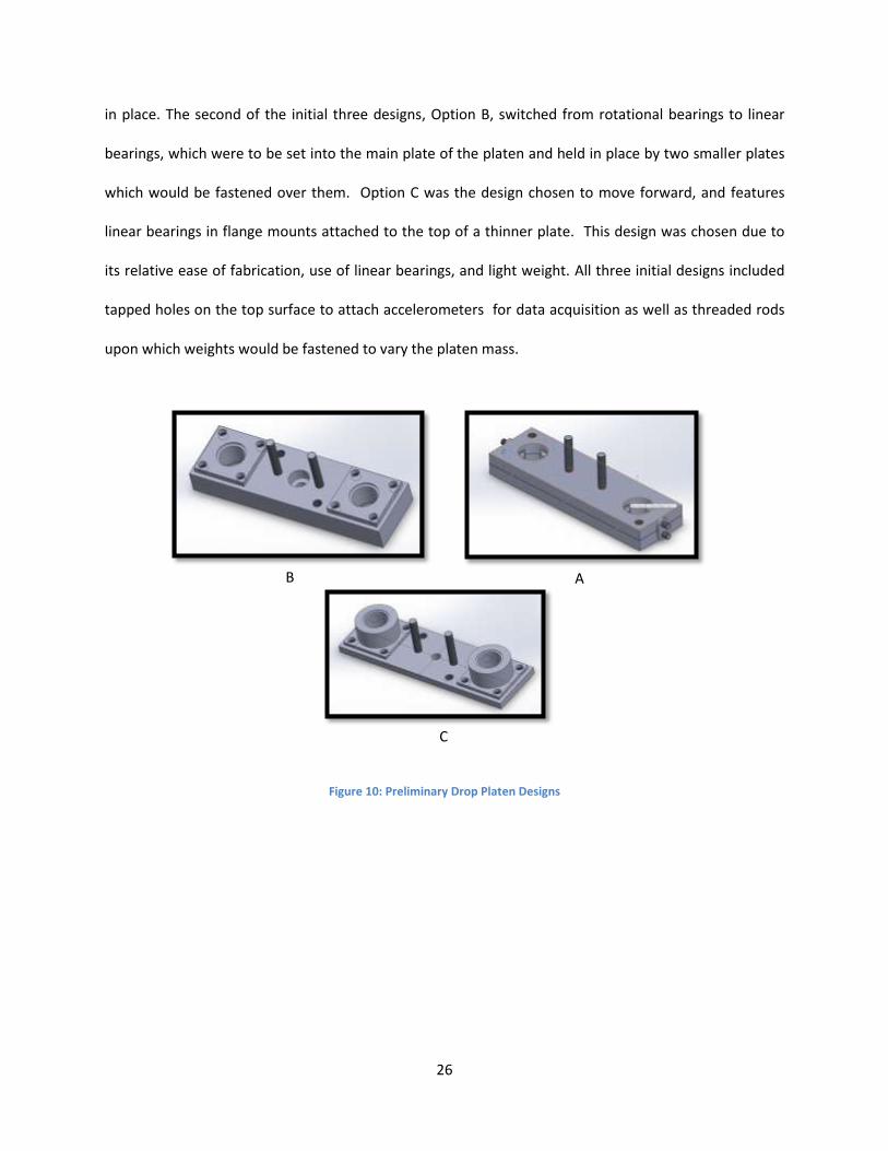
in place. The second of the initial three designs, Option B, switched from rotational bearings to linear
bearings, which were to be set into the main plate of the platen and held in place by two smaller plates
which would be fastened over them. Option C was the design chosen to move forward, and features
linear bearings in flange mounts attached to the top of a thinner plate. This design was chosen due to
its relative ease of fabrication, use of linear bearings, and light weight. All three initial designs included
tapped holes on the top surface to attach accelerometers for data acquisition as well as threaded rods
upon which weights would be fastened to vary the platen mass.
Figure 10: Preliminary Drop Platen Designs
C
A B

27
Figure 11: Optimized two guide rail design
During the design review process concerns about hitching were brought up. In order to prevent
this, a spring loaded bearing assembly could be manufactured, or two more guide rails could be added;
the latter was chosen for simplicity and ease of manufacture. The four guide rails were now arranged in
a square pattern requiring the redesign of the drop platen. To do this, two additional guide arms were
added perpendicular to the existing structure, resulting in a design resembling a plus sign. In order to
reduce stress concentrators a radius was added to the inner joint. A collar with a set screw was added to
Figure 12 Final Drop Platen Design

28
the underside of the drop platen to allow for easy transition between differently sized penetrators. On
the top surface of the drop platen a rod was added to allow for the use of interlocking test weights to
change the total drop mass. At the top of the rod there is a pin to allow for the quick release to pick up
the drop platen and bring it to the required drop height.
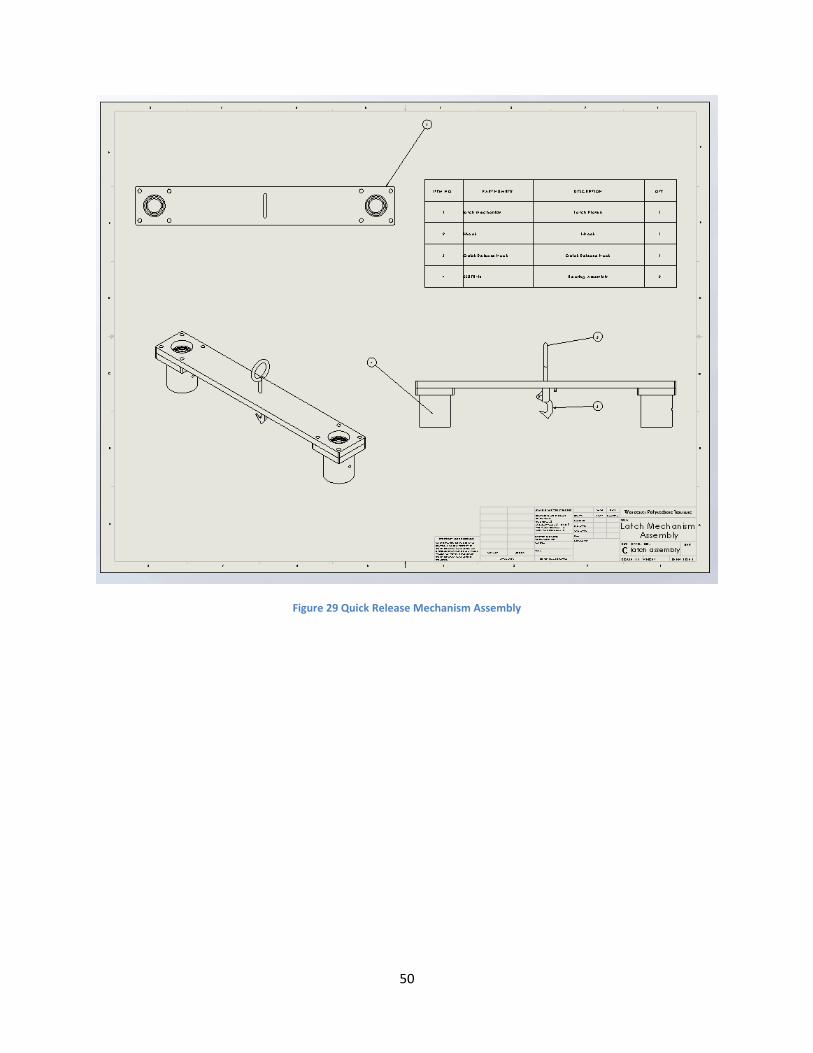
3.6 Quick Release Design
To allow for safe and simple operation of the drop tower a quick release latch was needed.
There are many types of quick release systems commercially available, however most of them are
expensive and almost none are designed for vertical loading. It became necessary to design a new quick
release that would handle vertical loads safely.
The design choices were narrowed down to the spring loaded hook assembly pictured below.
The hook will slide down on a separate carriage and pick up the drop platen. The carriage will carry the
Figure 13 Interlocking Test Weights

29
platen to the desired drop height. A pull cord can then be attached and used to trigger the drop. The
drop platen needed to be adjusted to accommodate the new quick release. The final quick release
assembly is pictured below and a diagram of the latch mechanism can be seen in Appendix D.
3.7 Safety Considerations
When working with drop towers there are several important safety issues that need to be
addressed. The most obvious issue is samples shattering upon impact. Another issue is that when
placing and adjusting the sample on the impact surface the drop mass must be suspended above the
surface. It is necessary to design safety systems and procedures to address these risks.
To address the issue of shattering samples the project team decided to install Plexiglas on the
four sides of the tower to prevent shattered test materials or parts from flying off during impact. This
will contain any debris and protect any instruments or people who may be in the lab. The project team
decided to use a self-locking hand crank winch and pulley system to raise and lower the drop platen. The
pulleys will be attached to the top of the structure supported by four aluminum beams. For safety
during loading, the initial design was to use stopping pins in the guide rails to stop the drop platen in the
event of the hand crank failing. This method would require holes bored in the guide rails and may
interfere with the drop motion and the bearings. In order to avoid this issue, PVC pipes of the same
length as the guide rails with a length-wise channel cut into them are placed over the pipes to catch the
drop platen. The pipes are a failsafe in the event that the quick release or winch lock failing. Inserting
these pipes underneath the drop platen will ensure that the drop platen does not fall onto the operator
underneath.

30
3.8 Instrumentation
The goal of the proposed design is to be able to measure the energy absorption of various
aerospace materials. The instrumentation for such measurements has been considered during the
design process and can be implemented in future projects. To measure the energy absorption of a
material, the area under the stress strain curve must be calculated. This means that both the stress and
strain values will need to be measured during testing.
𝜎 = 𝐹
𝐴
Where A is the area of the impact of the drop platen on the sample, which is a straightforward
calculation based on the size of the impactor being used. The impact force can be calculated using an
accelerometer and multiplying that data by the mass of the drop weight and the strain on the sample
can be directly measured with the use of strain gauges. The gauges need to be connected to a
Wheatstone bridge assembly to pick up on the small changes in voltage created by the physical strain on
the gauges. All of these measurements will be collected by a National Instruments Data Acquisition box
and processed with a LabVIEW code.
Predicting the peak acceleration caused by the impact depends on numerous factors and cannot
be easily calculated. Based on energy considerations it can be shown that:
𝑚𝑔ℎ = 𝐹𝛿
where δ is the deflection caused by the impact force F. Using Newton’s laws it can be stated that:
𝐹 = 𝑚𝑎𝑚𝑎𝑥
At the impact site, assuming that all gravitational potential energy is transferred into kinetic
energy, the equation can be simplified and solved for acceleration.

31
𝑎𝑚𝑎𝑥 =𝑣
2𝛿
2
Solving for δ is an altogether more difficult task. One empirical equation for the deflection
caused by a concentrated force applied at the center of a square plate that has been clamped on all four
sides is presented below.
𝛿 = 0.061 ×𝐹𝐴
𝐸𝑡3
In this case, A is the area of the test sample, E is the Young’s modulus of the sample material,
and t is the thickness of the sample. Using this equation in conjunction with the equation for amax a
reasonable estimate for the acceleration produced by the created impacts can be produced.
𝑎𝑚𝑎𝑥 = √𝑔ℎ𝐸𝑡3
0.061𝑚𝐴
This is a rough estimate but should provide a baseline acceleration to work from when selecting
the proper accelerometer. The table below shows some typical aerospace materials and lists their
Young’s moduli, maximum strain before breaking, and predicted amax.

32
Material Young’s Modulus (GPa) εmax (%) Predicted amax (g)
Al 2024-T6 72.4 5.0 414.5
Mg AZ91C 45.0 6.0 326.8
Al 6061-T4 69.0 12.0 404.6
Carbon Fiber BMI 67.0 0.76 320.2
Carbon Fiber Epoxy 68.7 0.93 324.2
Table 3 Sample Materials and Predicted Peak Acceleration
Selecting appropriate strain gauges for testing is a much less involved task than that for
selecting accelerometers. Looking at table 3 it can be observed that the range of εmax stretches from
0.76% to 16.3%. There are commercial models available capable of measuring strains from 0-20% and
one of these will be selected at a resistance of 120Ω to be compatible with the Wheatstone bridge
assembly that is currently available. Further selection criteria will be size, cost, and availability.

33
5. Conclusions and Recommendations for Future Work
The final design focuses on optimizing the functionality and safety of the drop tower while
keeping the total cost as low as possible. This means that the final design does not include advanced
functions available in expensive commercial drop towers such as a pneumatic brake system and a
velocity augmentation system to simulate higher drops. Further improvements for future work may
include the design of these systems: the brake system can help prevent the impactor from striking the
test specimen twice in the event that it bounces, and the velocity and height adjustment allows for a
wider range of impact energy. Also not included in the final design is a finalized data acquisition system
which was initially to be incorporated when the tower was to be built. Future project teams may explore
the best options for data acquisition including a refined estimate for the G-force loading on the
accelerometers generated by impact. This will require actual impact test on all available ranges of
impact energy. It is also encouraged that future teams measure and record the maximum impact energy
and velocity with the effects of friction at each different drop weight setting for reference.
Materials selection is a vital process in Aerospace Engineering; testing materials is a way to
ensure structural integrity in aircraft. Overall, the project team feels confident that the design, having
gone through many detailed and careful design iterations, will allow for a functioning impact drop tower
to be constructed inexpensively and used for aerospace applications in the future.

34
6. References
[1] About ASTM International [Online]. Available: http://www.astm.org/ABOUT/overview.html
[Accessed 10/06/2014.]
[2] Gooch, Jan W. "Charpy Impact Test." Encyclopedic Dictionary of Polymers. New York: Springer, 2007. 179-80, 404, 449-450. [Online]. Available: http://au4sb9ax7m.search.serialssolutions.com/?ctx_ver=Z39.88-2004&ctx_enc=info%3Aofi%2Fenc%3AUTF-8&rfr_id=info:sid/summon.serialssolutions.com&rft_val_fmt=info:ofi/fmt:kev:mtx:book&rft.genre=book%20item&rft.title=Encyclopedic+Dictionary+of+Polymers&rft.atitle=Charpy+Impact+Test&rft.date=2007-01-01&rft.pub=Springer&rft.isbn=9780387310213&rft.spage=179&rft.epage=180&rft.externalDocID=3042801964¶mdict=en-US [Accessed: 10/6/2014][3] [Subcommittee D10.13]. Standard Test Method for Dynamic Shock Characteristics of Packaging Material [online] May 2014. Available from http://enterprise.astm.org/SUBSCRIPTION/NewValidateSubscription.cgi?D1596-HTML. Accessed 9/18/2014
[4] [Subcommittee D20.10]. Standard Test Method for High Speed Puncture Properties of Plastics Using Load and Displacement Sensors [online] July 2010. Available from http://enterprise.astm.org/SUBSCRIPTION/NewValidateSubscription.cgi?D3763-HTML. Accessed 9/18/2014
[5] [Subcommittee F08.52]. Standard Specification for Shock Attenuation Properties of Fencing Surfaces [online] May 2014. Available from http://enterprise.astm.org.ezproxy.wpi.edu/SUBSCRIPTION/filtrexx40.cgi?REDLINE_PAGES/F1543.htm Accessed 9/18/2014

35
Appendix A: CAD Drawings
Figure 14 Full Tower

36
Figure 15 Full Tower Assembly Drawing

37
Figure 16 Tower Base

38
Figure 17 Mounts for Leveling Screws
39
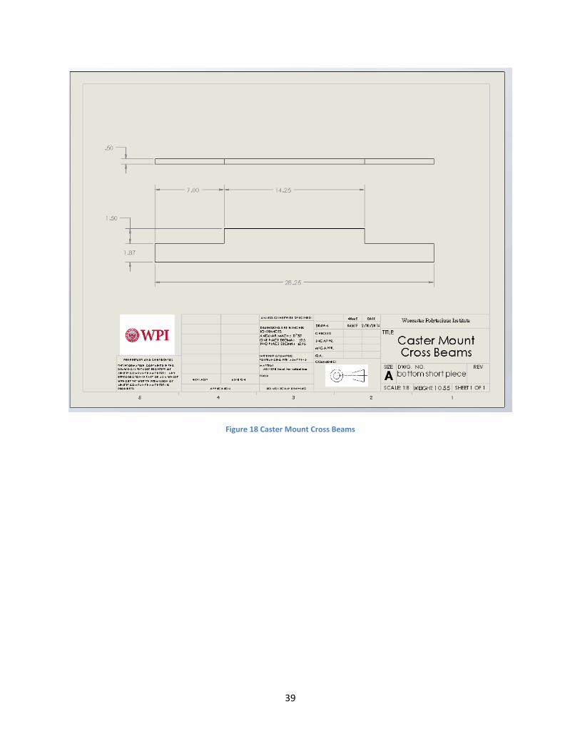
Figure 18 Caster Mount Cross Beams
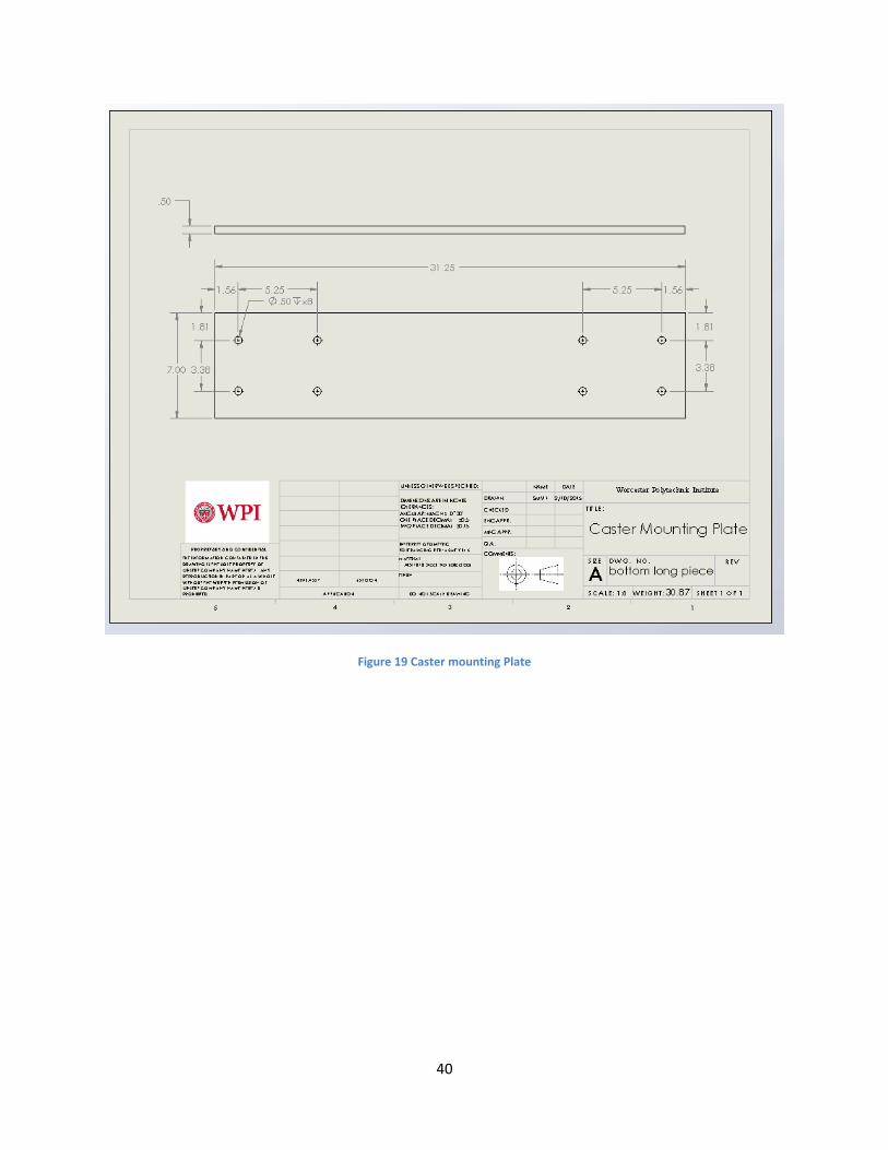
40
Figure 19 Caster mounting Plate

41
Figure 20 Leveling Screws Mounting Plate
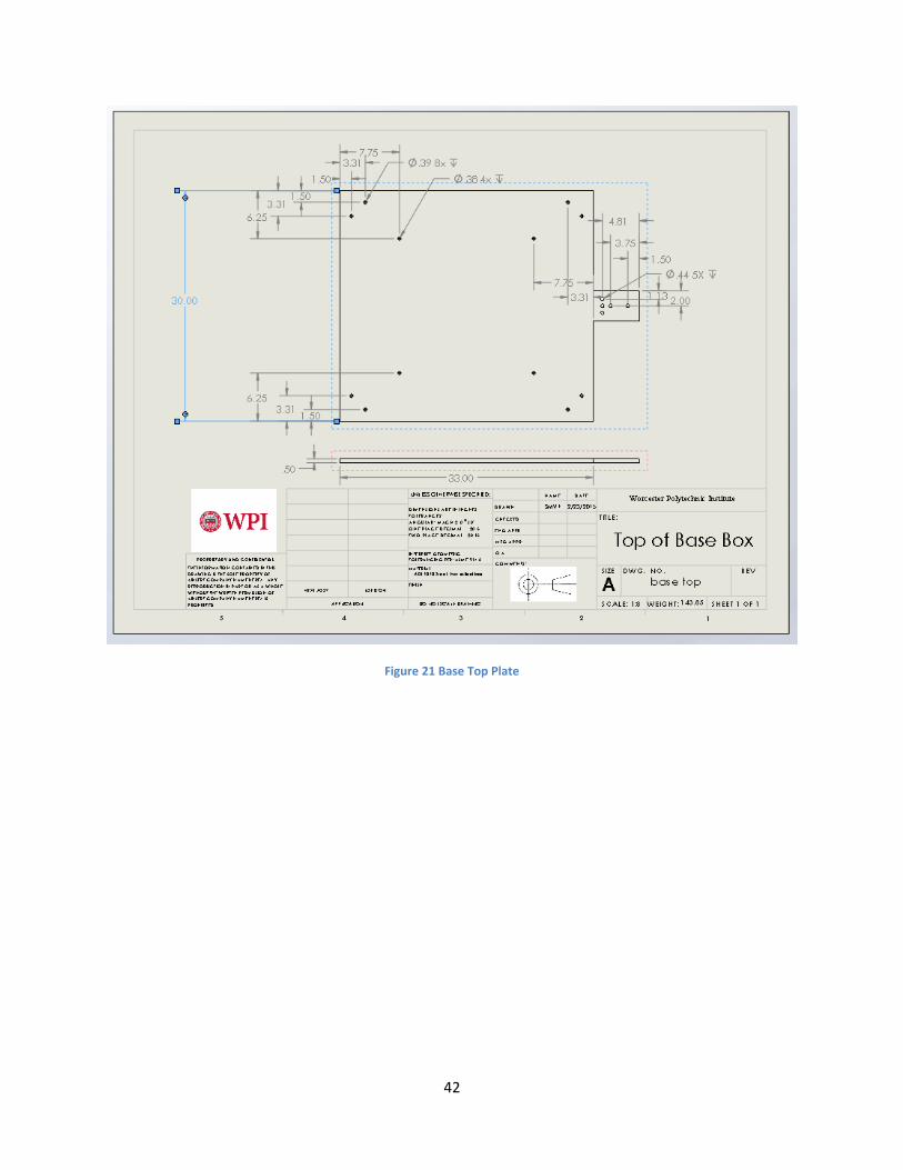
42
Figure 21 Base Top Plate

43
Figure 22 Base Short Side

44
Figure 23 Base Long Side

45
Figure 24 Tower Base Assembly

46
Figure 25 Drop Platen with Penetrator

47
Figure 26 Latch Mechanism Hook
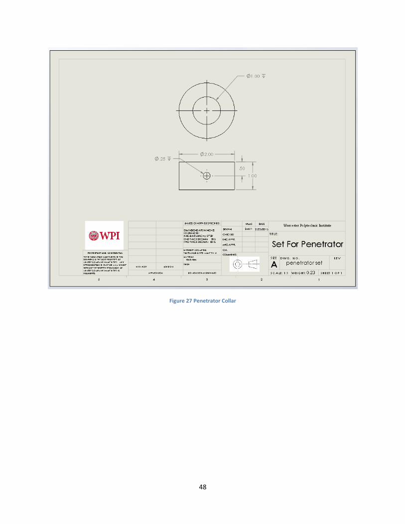
48
Figure 27 Penetrator Collar
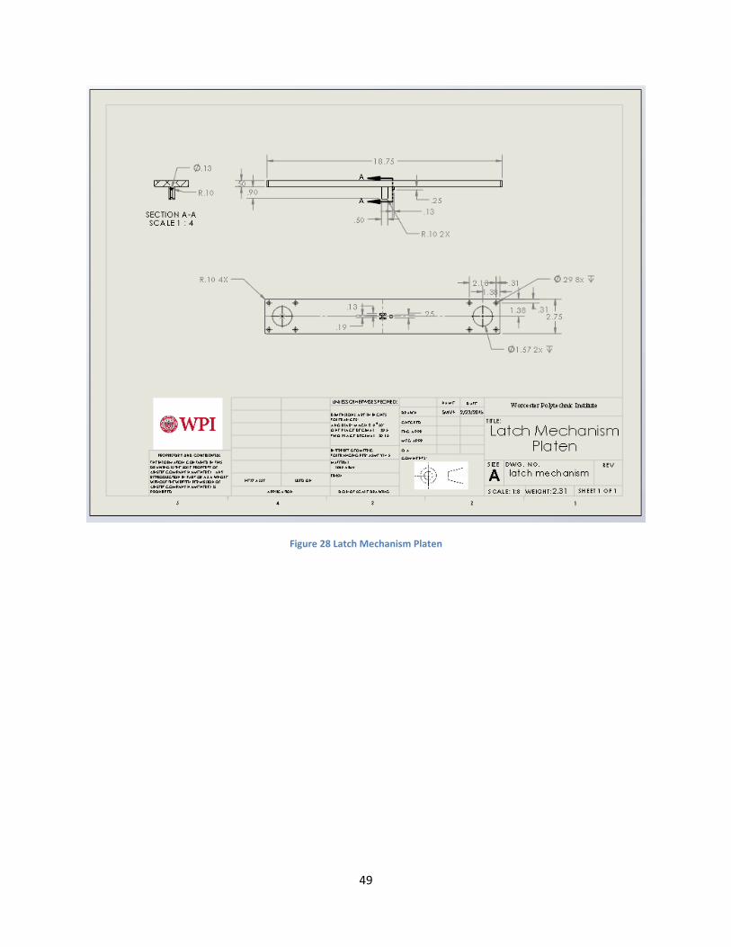
49
Figure 28 Latch Mechanism Platen
50
Figure 29 Quick Release Mechanism Assembly

51
Figure 30 Half Inch Penetrator

52
Figure 31 Three Quarter Inch Penetrator
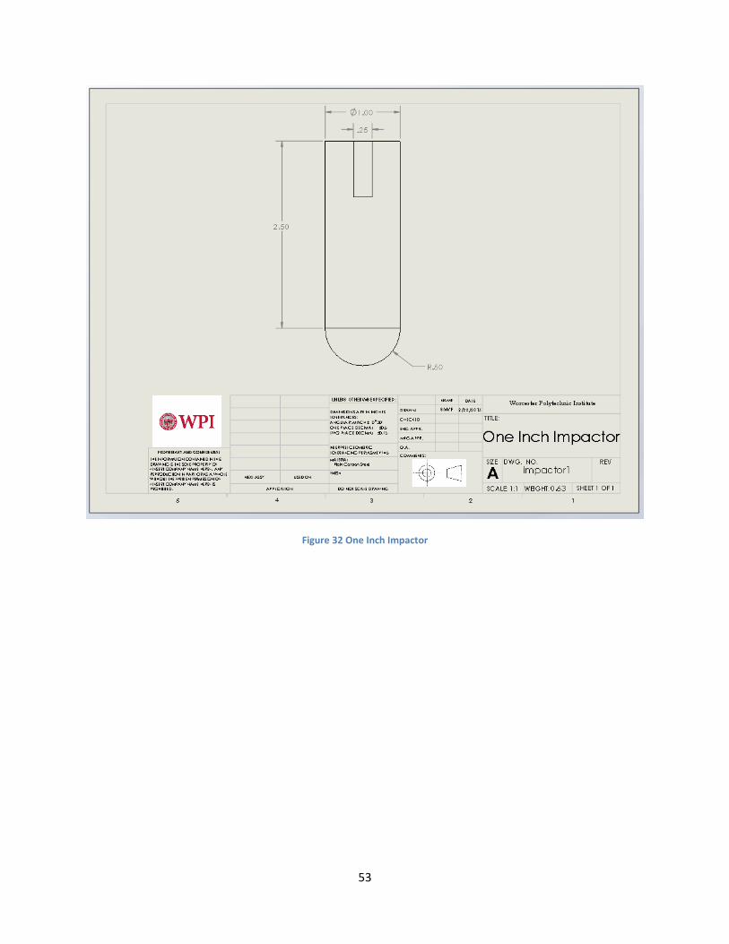
53
Figure 32 One Inch Impactor
54
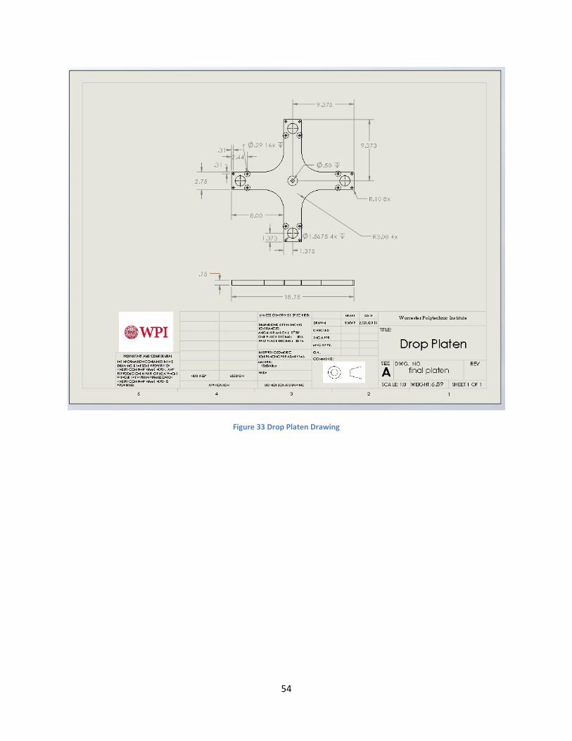
Figure 33 Drop Platen Drawing
55
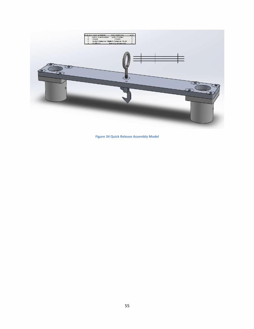
Figure 34 Quick Release Assembly Model

56
Figure 35 Sample Mount

57
Figure 36 Sample Mounting Platform
58
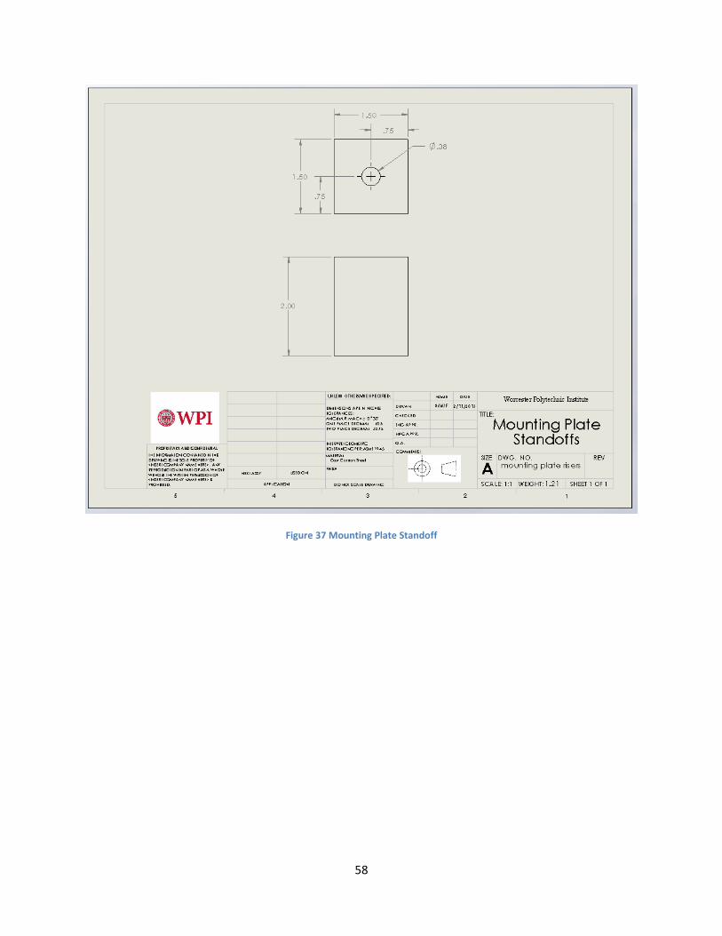
Figure 37 Mounting Plate Standoff

59
Figure 38 Sample Mounting Platform Assembly
60
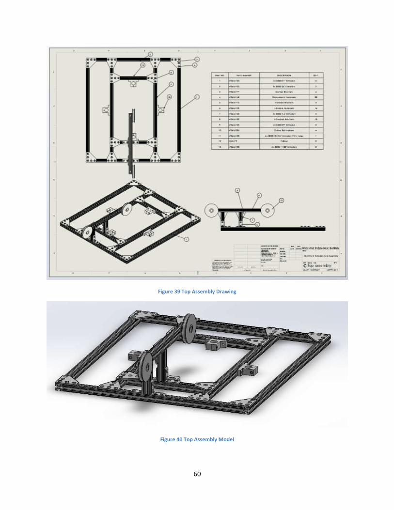
Figure 39 Top Assembly Drawing
Figure 40 Top Assembly Model

61
Appendix B: Bill of Materials
Description Distributor Part Number Price per Part Quantity Price
Plate Mounts McMaster 47065T65 8.72 8 69.76
AL 8020 72" Extrusions McMaster 47065T123 26.38 10 263.8
Plate Mount Fasteners McMaster 47065T142 2.30 134 77.05
L Brackets McMaster 47065T175 4.56 36 164.16
L Bracket Fasteners McMaster 47065T139 1.85 144 66.6
Panel Holders McMaster 47065T195 4.95 39 193.05
Acrylic Panels McMaster 8560K228 196.94 4 787.76
Door Hinges McMaster 47065T162 9.15 4 36.6
Door Latch McMaster 47065T57 20.95 2 41.9
Corner Brackets McMaster 47065T177 6.70 6 40.2
T Brackets McMaster 47065T182 7.58 10 75.8
Guide Rail Holders McMaster 47065T205 34.10 4 136.4
Pulleys McMaster 3434T79 18.67 2 37.34
Guide Rail Flange Mounts McMaster 4936T416 26.73 4 106.92
Linear Bearings Thomson Linear SSUFB-16 N/A 6 0
Guide Rails Thomson Linear
SSUFB-16_TEMP N/A 4 0
Total 2097.34

62
Appendix C: User Manual User Manual
General Safety Precautions
Impact testing for materials involves hazards from high impact forces. Users must be aware of all moving
components of the assembly, especially the drop platen and weight raising mechanism. Take care when
installing or removing a specimen or assemble.
Warning
1. Keep any part of body out of the path of falling weight and impactor at all times.
2. Only one operator should operate inside the test chamber at any given time. Also when a
person is operating inside the test chamber, no other person should operate the winch.
3. Perform regular maintenance.
4. Keep the protective Plexiglas door closed at all times during drop and when raising or
lowering the quick release carriage and drop platen.
5. Do not leave objects inside the chamber during operation.
6. Do not use impactor to strike non-deformable objects.
7. Frequently check the lifting cable for damage
8. Only add or remove drop weights when both the quick release carriage and the drop platen
are in their starting positions (see Operation below.)
63
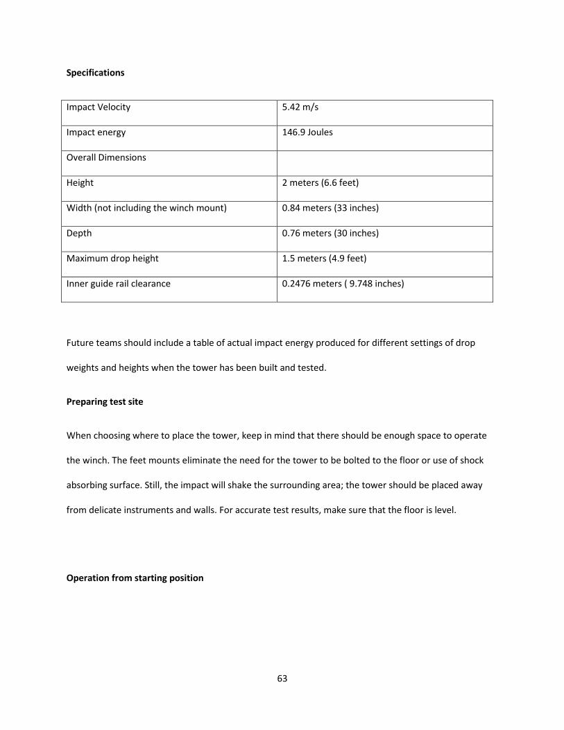
Specifications
Impact Velocity 5.42 m/s
Impact energy 146.9 Joules
Overall Dimensions
Height 2 meters (6.6 feet)
Width (not including the winch mount) 0.84 meters (33 inches)
Depth 0.76 meters (30 inches)
Maximum drop height 1.5 meters (4.9 feet)
Inner guide rail clearance 0.2476 meters ( 9.748 inches)
Future teams should include a table of actual impact energy produced for different settings of drop
weights and heights when the tower has been built and tested.
Preparing test site
When choosing where to place the tower, keep in mind that there should be enough space to operate
the winch. The feet mounts eliminate the need for the tower to be bolted to the floor or use of shock
absorbing surface. Still, the impact will shake the surrounding area; the tower should be placed away
from delicate instruments and walls. For accurate test results, make sure that the floor is level.
Operation from starting position

64
The starting position of the quick release carriage should always be either the drop height used in a
previous test or at the top of the guide rails with the winch locked. The starting position of the drop
platen is at the bottom resting on the flange mounts. Close the Plexiglas door at the end of testing.
1. Attached desired weight to the drop platen, aligning the space of the interlocking test weights
with the drop platen rod.
2. Close the Plexiglas door. Unlock the winch. Lower the quick release carriage until the hook picks
up the pin on top of the drop platen.
3. Raise the carriage, along with the drop platen, to the top of the guide rails. Lock the winch to
prevent the weight from falling.
4. Open the Plexiglas door. Insert the cut PVC pipes onto the rails. Unlock the winch and gently
lower the drop platen so that it rests on the PVC pipes. Lock the winch again.
5. Unscrew the wing nuts on the t-bolts fastening the test platforms. Slide and adjust the inner
edge of the indentation, on which the sample will rest, of one platform to the corresponding
sample size indicated by demarcations along the grooved track. Screw the wing nut and fasten
the t-bolts to hold the platform in place.
6. Place one side of the sample on this fixed platform and clamp the sample down using the toggle
clamp. Adjust and fasten the remaining three platforms so that the sample rests clamped on the
four platforms. The four sides of the sample should align with its size demarcation.
7. Make sure there is no debris in the test chamber. Remove the PVC pipes from the guide rails.
8. Unlock the winch. Lower the drop platen to the desired drop height. Lock the winch.
9. Close the Plexiglas door.
10. Double check the data acquisition system. When ready, pull the quick release cord. The drop
platen will be released and the impactor will fall onto the mounted sample.
11. Obtain data from the data acquisition system.

65
12. Repeat steps 2 to 4.
13. Unscrew the wing nuts of two drop platforms closest to the Plexiglas door. Unclamp the sample
on the two sides. Slide the platforms out. Unclamp the sample on the other two sides. Remove
the sample.
14. A) If conducting further tests using the same drop weights: Simply repeat steps 5 to 13.
B) If conducting further tests using different drop weights: Return the drop platen and the
quick release to their starting positions before changing weights: Remove the PVC pipes,
close the Plexiglas door, gently lower the drop platen until it rests on the flange mounts, pull
and hold the release chord, raise the carriage to the top of the guide rails and lock the winch
(this may require an additional operator to hold the cord until the hook clears the drop
platen pin).Then repeat the process from step 1 to 13.
C) If not conducting any further tests: Return the drop platen and the quick release carriage to
their starting positions (see section B above.) Then remove the weights, clean up the test
chamber, and close the Plexiglas door.

66
Appendix D: Quick Release Latch Mechanism Diagram

67

68

69