DRM159, Automotive HVAC Control System with LCD Interface ... · Automotive HVAC Control System...
58
Automotive HVAC Control System with LCD Interface for S12HY Family Devices Document Number: DRM159 Rev. 0 03/2015
Transcript of DRM159, Automotive HVAC Control System with LCD Interface ... · Automotive HVAC Control System...
Automotive HVAC Control System with LCD Interface for S12HY Family Devices
Document Number: DRM159 Rev. 0
03/2015

Automotive HVAC Control System with LCD Interface
2 Freescale Semiconductor, Inc.
Automotive HVAC Control System with LCD Interface Freescale Semiconductor, Inc. 3
CHAPTER 1
INTRODUCTION
1.1. APPLICATION FEATURES AND COMPONENTS ....................................................................................................................... 5 1.2. MC9S12HY64 CONTROLLER ADVANTAGES AND FEATURES .................................................................................................. 6
CHAPTER 2 HARDWARE DESCRIPTION
2.1. INTRODUCTION ............................................................................................................................................................. 8 2.2. HARDWARE INTERFACE ................................................................................................................................................... 9
2.2.1. Power supply........................................................................................................................................................ 9 2.2.2. MC9S12HY64 MCU............................................................................................................................................. 10 2.2.3. Liquid Crystal Display (LCD) ................................................................................................................................ 16 2.2.4. Actuator motor driver ........................................................................................................................................ 17 2.2.5. Blower motor driver........................................................................................................................................... 17 2.2.6. MC9S08PT60 for touch sense ............................................................................................................................ 19 2.2.7. IR receiver .......................................................................................................................................................... 20 2.2.8. Temperature sensor ........................................................................................................................................... 20 2.2.9. Controller Area Network (CAN) ......................................................................................................................... 21 2.2.10. Background debug mode (BDM) ................................................................................................................... 21
CHAPTER 3 SOFTWARE DESIGN
3.1. INTRODUCTION ........................................................................................................................................................... 23 3.2. SOFTWARE ARCHITECTURE ............................................................................................................................................ 23
3.2.1. LCD graphics display ........................................................................................................................................... 25 3.2.2. User interface .................................................................................................................................................... 27 3.2.3. Motor control..................................................................................................................................................... 30 3.2.4. Temperature sensor ........................................................................................................................................... 32 3.2.5. Real time clock ................................................................................................................................................... 32
CHAPTER 4 TESTING AND MEASUREMENTS
4.1. HARDWARE SETUP ....................................................................................................................................................... 33 4.2. DEBUGGING AND MEASUREMENT ................................................................................................................................... 34
4.2.1. LCD ..................................................................................................................................................................... 34 4.2.2. User interface .................................................................................................................................................... 35 4.2.3. Motor control..................................................................................................................................................... 37
4.3. TEMPERATURE SENSOR ................................................................................................................................................. 45
APPENDIX A
A.1 SCHEMATIC ................................................................................................................................................................ 46 A.2 LAYOUT ..................................................................................................................................................................... 51
A.2.1 Silkscreen Top .................................................................................................................................................... 51 A.2.2 Silkscreen Bottom .............................................................................................................................................. 51 A.2.3 Top ..................................................................................................................................................................... 52 A.2.4 Bottom ............................................................................................................................................................... 52
APPENDIX B BILL OF MATERIAL
Automotive HVAC Control System with LCD Interface
4 Freescale Semiconductor, Inc.
Chapter 1 Introduction This document describes the reference design of an automotive Heating, Ventilation, and Air Conditioning (HVAC) control system with LCD interface board based on MC9S12HY64.
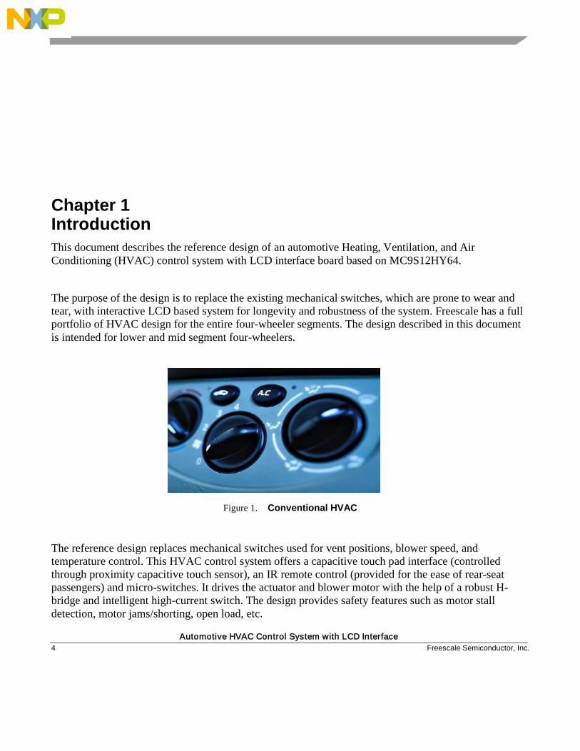
The purpose of the design is to replace the existing mechanical switches, which are prone to wear and tear, with interactive LCD based system for longevity and robustness of the system. Freescale has a full portfolio of HVAC design for the entire four-wheeler segments. The design described in this document is intended for lower and mid segment four-wheelers.
Figure 1. Conventional HVAC
The reference design replaces mechanical switches used for vent positions, blower speed, and temperature control. This HVAC control system offers a capacitive touch pad interface (controlled through proximity capacitive touch sensor), an IR remote control (provided for the ease of rear-seat passengers) and micro-switches. It drives the actuator and blower motor with the help of a robust H-bridge and intelligent high-current switch. The design provides safety features such as motor stall detection, motor jams/shorting, open load, etc.
Introduction
Automotive HVAC Control System with LCD Interface Freescale Semiconductor, Inc. 5
The design also features car cabin’s temperature (in degree Celsius) display, date and time displays, thus eliminating the need of separate date/time/temperature displays. Date/Time can be easily set through touch pads/remote control.
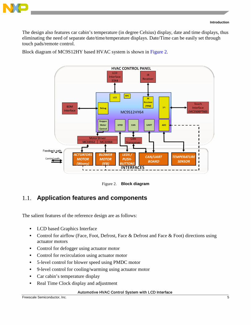
Block diagram of MC9S12HY based HVAC system is shown in Figure 2.
Figure 2. Block diagram
1.1. Application features and components The salient features of the reference design are as follows:
• LCD based Graphics Interface • Control for airflow (Face, Foot, Defrost, Face & Defrost and Face & Foot) directions using
actuator motors • Control for defogger using actuator motor • Control for recirculation using actuator motor • 5-level control for blower speed using PMDC motor • 9-level control for cooling/warming using actuator motor • Car cabin’s temperature display • Real Time Clock display and adjustment
Introduction
Automotive HVAC Control System with LCD Interface 6 Freescale Semiconductor, Inc.
• Date display and adjustment • IR remote interface • 8 Touch pad interface using PT60 MCU • Low Power Mode interfaced through Ignition
The package that shall be supplied to the user for developing the HVAC system based on MC9S12HY64 MCU includes:
• Hardware – Reference HVAC board • Documentation – DRM, BOM, Schematics
1.2. Advantages and features of MC9S12HY64 controller Advantage of using MC9S12HY64:
• In-built LCD driver capable of driving 160 segments • Stepper Motor Controller • Low-voltage detect (LVD) with low-voltage interrupt (LVI) and Low-voltage reset (LVR) • MCU security mechanism that prevents unauthorized access to the Flash memory • Two static low-power modes Pseudo Stop and Stop mode to facilitate power saving when full
system performance is not required The general features of MC9S12HY64 MCU are:
• HCS12 CPU core, 32 MHz bus frequency (64 MHZ core frequency) • Up to 64 KB on-chip flash with ECC • 4 KB data flash with ECC • Up to 4 KB on-chip SRAM • LCD driver, configurable up to 40 x 4, all LCD pins are multiplexed with GPIOs • Stepper motor controller with up to four drivers • Phase locked loop (PLL) frequency multiplier with internal filter • 4–16 MHz amplitude controlled Pierce oscillator • 1 MHz internal RC oscillator • Two timer modules (TIM0 and TIM1) supporting input/output channels that provide a range of
16-bit input capture, output compare, counter, and pulse accumulator functions • Pulse width modulation (PWM) module with up to eight 8-bit channels • Autonomous periodic interrupt (API) • Up to 8-channel, 10-bit resolution successive approximation analog-to-digital converter (ATD) • One serial peripheral interface (SPI) module • One serial communication interface (SCI) module supporting LIN 2.0, 2.1, and SAE J2602
communications
Introduction
Automotive HVAC Control System with LCD Interface Freescale Semiconductor, Inc. 7
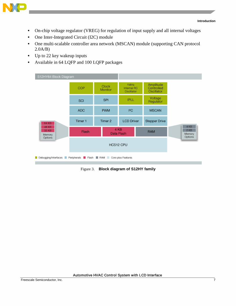
• On-chip voltage regulator (VREG) for regulation of input supply and all internal voltages • One Inter-Integrated Circuit (I2C) module • One multi-scalable controller area network (MSCAN) module (supporting CAN protocol
2.0A/B) • Up to 22 key wakeup inputs • Available in 64 LQFP and 100 LQFP packages
Figure 3. Block diagram of S12HY family
Hardware Description
Automotive HVAC Control System with LCD Interface 8 Freescale Semiconductor, Inc.
Chapter 2 Hardware Description
2.1. Introduction The reference design consists of:
• Power supply section • 100-pin LQFP packaged MC9S12HY64 MCU • 132 segment (33X4) LCD Glass interface with backlight control • Dual Intelligent High-current Self-protected Silicon High Side Switch, MC33984, capable of
driving two blower motors of 15 A each • Two Throttle Control H-Bridge, MC33932, for controlling four high current actuator motors,
three of these are used for temperature, vent position, and re-circulation, while one of the motor control has been kept for future use
• 64-pin MC9S08PT60 which has Touch Sense Input (TSI) module for eight touch pad interface • IR remote interface, provided especially for the ease of control for rear-seat passengers • Temperature sensor, for measuring the car’s cabin temperature • CAN interface for communication with various other units • Ignition control section for low-power mode simulation
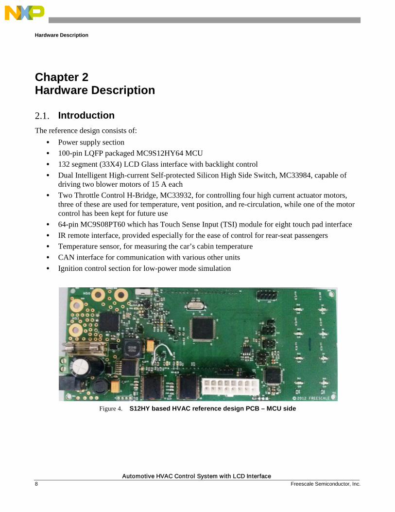
Figure 4. S12HY based HVAC reference design PCB – MCU side
Hardware Description
Automotive HVAC Control System with LCD Interface Freescale Semiconductor, Inc. 9
Figure 5. S12HY based HVAC reference design PCB – LCD side
2.2. Hardware interface The following section details each hardware block with the corresponding schematic.
2.2.1. Power supply The reference design board is switched on from an automotive battery, 12 V, 32 AH. It is connected directly with
• Blower motor driver, MC33984, as the blower motor is 12 V compatible • Actuator motor driver, MC33932, as the actuator motors are 12 V compatible
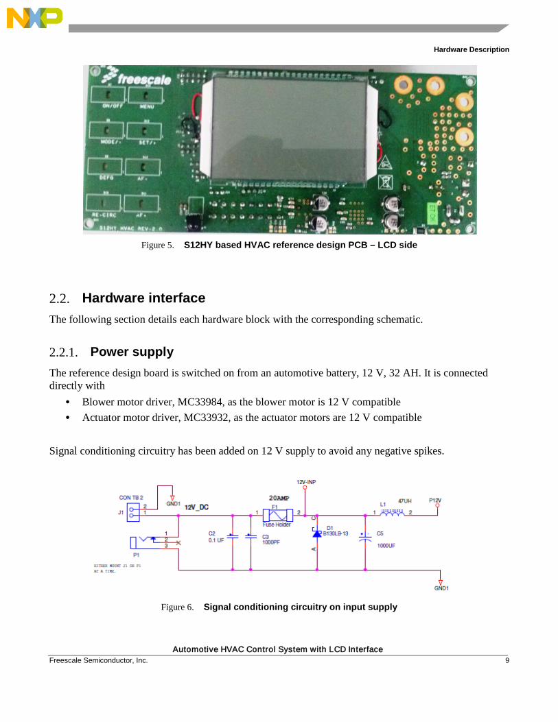
Signal conditioning circuitry has been added on 12 V supply to avoid any negative spikes.
Figure 6. Signal conditioning circuitry on input supply
Hardware Description
Automotive HVAC Control System with LCD Interface 10 Freescale Semiconductor, Inc.
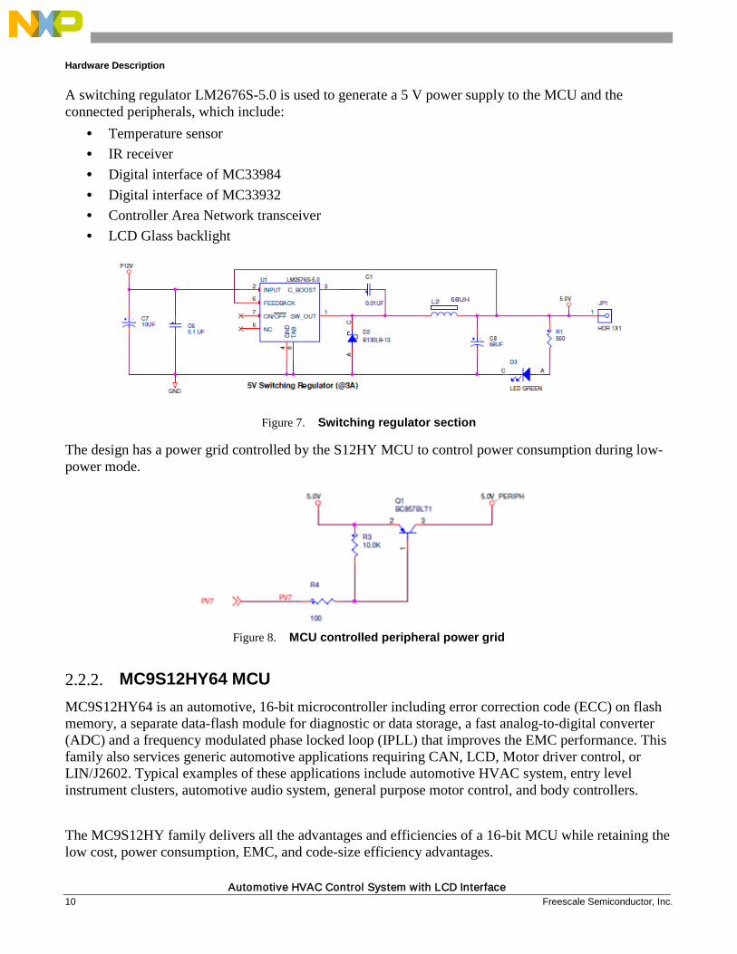
A switching regulator LM2676S-5.0 is used to generate a 5 V power supply to the MCU and the connected peripherals, which include:
• Temperature sensor • IR receiver • Digital interface of MC33984 • Digital interface of MC33932 • Controller Area Network transceiver • LCD Glass backlight
Figure 7. Switching regulator section
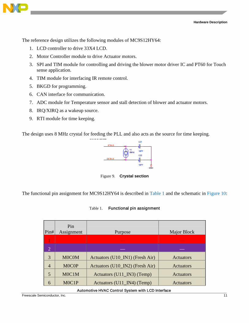
The design has a power grid controlled by the S12HY MCU to control power consumption during low- power mode.
Figure 8. MCU controlled peripheral power grid
2.2.2. MC9S12HY64 MCU MC9S12HY64 is an automotive, 16-bit microcontroller including error correction code (ECC) on flash memory, a separate data-flash module for diagnostic or data storage, a fast analog-to-digital converter (ADC) and a frequency modulated phase locked loop (IPLL) that improves the EMC performance. This family also services generic automotive applications requiring CAN, LCD, Motor driver control, or LIN/J2602. Typical examples of these applications include automotive HVAC system, entry level instrument clusters, automotive audio system, general purpose motor control, and body controllers.
The MC9S12HY family delivers all the advantages and efficiencies of a 16-bit MCU while retaining the low cost, power consumption, EMC, and code-size efficiency advantages.
Hardware Description
Automotive HVAC Control System with LCD Interface Freescale Semiconductor, Inc. 11
The reference design utilizes the following modules of MC9S12HY64:
1. LCD controller to drive 33X4 LCD.
2. Motor Controller module to drive Actuator motors.
3. SPI and TIM module for controlling and driving the blower motor driver IC and PT60 for Touch sense application.
4. TIM module for interfacing IR remote control.
5. BKGD for programming.
6. CAN interface for communication.
7. ADC module for Temperature sensor and stall detection of blower and actuator motors.
8. IRQ/XIRQ as a wakeup source.
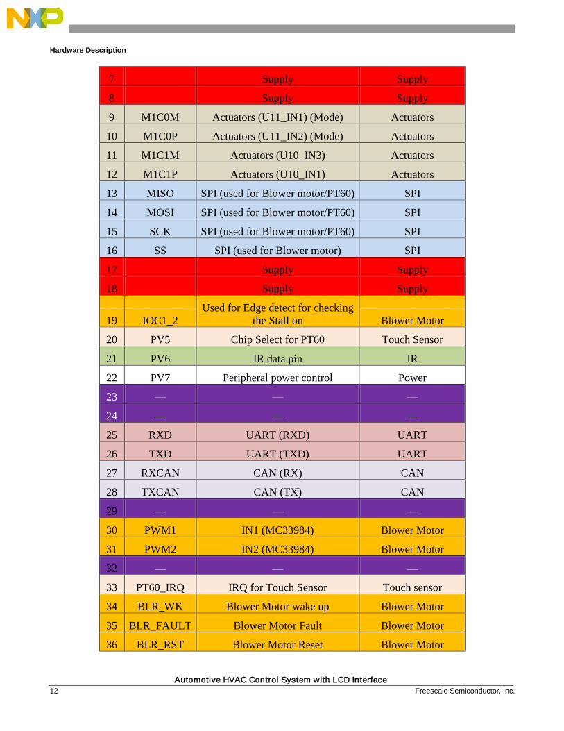
9. RTI module for time keeping. The design uses 8 MHz crystal for feeding the PLL and also acts as the source for time keeping.
Figure 9. Crystal section
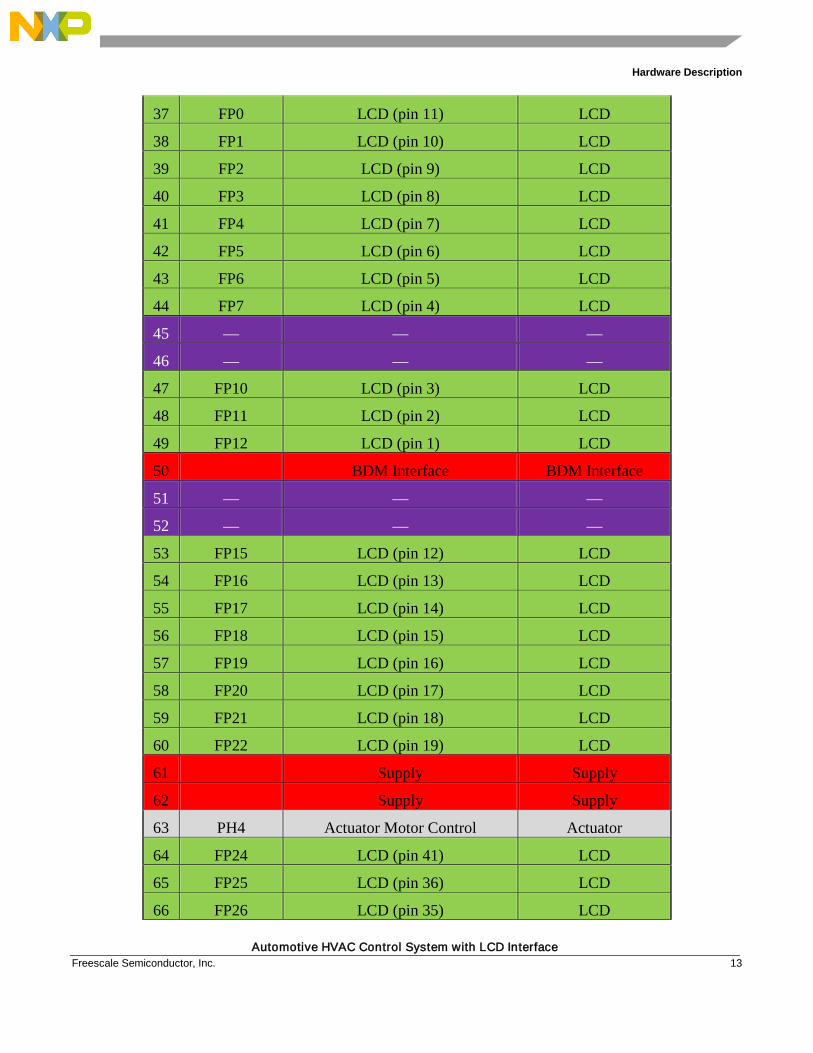
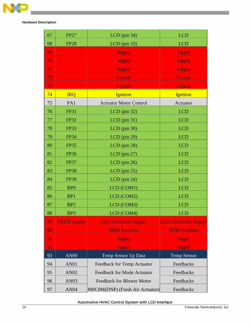
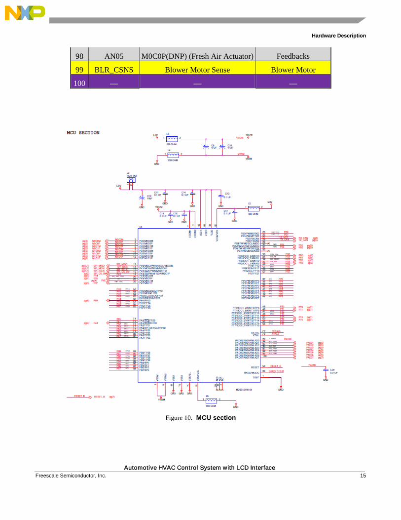
The functional pin assignment for MC9S12HY64 is described in Table 1 and the schematic in Figure 10:
Table 1. Functional pin assignment
Pin# Pin
Assignment Purpose Major Block
1 — —
2 — —
3 M0C0M Actuators (U10_IN1) (Fresh Air) Actuators
4 M0C0P Actuators (U10_IN2) (Fresh Air) Actuators
5 M0C1M Actuators (U11_IN3) (Temp) Actuators
6 M0C1P Actuators (U11_IN4) (Temp) Actuators
Hardware Description
Automotive HVAC Control System with LCD Interface 12 Freescale Semiconductor, Inc.
7 Supply Supply
8 Supply Supply
9 M1C0M Actuators (U11_IN1) (Mode) Actuators
10 M1C0P Actuators (U11_IN2) (Mode) Actuators
11 M1C1M Actuators (U10_IN3) Actuators
12 M1C1P Actuators (U10_IN1) Actuators
13 MISO SPI (used for Blower motor/PT60) SPI
14 MOSI SPI (used for Blower motor/PT60) SPI
15 SCK SPI (used for Blower motor/PT60) SPI
16 SS SPI (used for Blower motor) SPI
17 Supply Supply
18 Supply Supply
19 IOC1_2 Used for Edge detect for checking
the Stall on Blower Motor
20 PV5 Chip Select for PT60 Touch Sensor
21 PV6 IR data pin IR
22 PV7 Peripheral power control Power
23 — — —
24 — — —
25 RXD UART (RXD) UART
26 TXD UART (TXD) UART
27 RXCAN CAN (RX) CAN
28 TXCAN CAN (TX) CAN
29 — — —
30 PWM1 IN1 (MC33984) Blower Motor
31 PWM2 IN2 (MC33984) Blower Motor
32 — — —
33 PT60_IRQ IRQ for Touch Sensor Touch sensor
34 BLR_WK Blower Motor wake up Blower Motor
35 BLR_FAULT Blower Motor Fault Blower Motor
36 BLR_RST Blower Motor Reset Blower Motor
Hardware Description
Automotive HVAC Control System with LCD Interface Freescale Semiconductor, Inc. 13
37 FP0 LCD (pin 11) LCD
38 FP1 LCD (pin 10) LCD
39 FP2 LCD (pin 9) LCD
40 FP3 LCD (pin 8) LCD
41 FP4 LCD (pin 7) LCD
42 FP5 LCD (pin 6) LCD
43 FP6 LCD (pin 5) LCD
44 FP7 LCD (pin 4) LCD
45 — — —
46 — — —
47 FP10 LCD (pin 3) LCD
48 FP11 LCD (pin 2) LCD
49 FP12 LCD (pin 1) LCD
50 BDM Interface BDM Interface
51 — — —
52 — — —
53 FP15 LCD (pin 12) LCD
54 FP16 LCD (pin 13) LCD
55 FP17 LCD (pin 14) LCD
56 FP18 LCD (pin 15) LCD
57 FP19 LCD (pin 16) LCD
58 FP20 LCD (pin 17) LCD
59 FP21 LCD (pin 18) LCD
60 FP22 LCD (pin 19) LCD
61 Supply Supply
62 Supply Supply
63 PH4 Actuator Motor Control Actuator
64 FP24 LCD (pin 41) LCD
65 FP25 LCD (pin 36) LCD
66 FP26 LCD (pin 35) LCD
Hardware Description
Automotive HVAC Control System with LCD Interface 14 Freescale Semiconductor, Inc.
67 FP27 LCD (pin 34) LCD
68 FP28 LCD (pin 33) LCD
69 Supply Supply
70 Supply Supply
71 Supply Supply
72 Crystal Crystal
73 Crystal Crystal
74 IRQ Ignition Ignition
75 PA1 Actuator Motor Control Actuator
76 FP31 LCD (pin 32) LCD
77 FP32 LCD (pin 31) LCD
78 FP33 LCD (pin 30) LCD
79 FP34 LCD (pin 29) LCD
80 FP35 LCD (pin 28) LCD
81 FP36 LCD (pin 27) LCD
82 FP37 LCD (pin 26) LCD
83 FP38 LCD (pin 25) LCD
84 FP39 LCD (pin 24) LCD
85 BP0 LCD (COM1) LCD
86 BP1 LCD (COM2) LCD
87 BP2 LCD (COM3) LCD
88 BP3 LCD (COM4) LCD
89 VLCD supply LCD Controller Supply LCD Controller Supply
90 BDM Interface BDM Interface
91 Supply Supply
92 Supply Supply
93 AN00 Temp Sensor I/p Data Temp Sensor
94 AN01 Feedback for Temp Actuator Feedbacks
95 AN02 Feedback for Mode Actuator Feedbacks
96 AN03 Feedback for Blower Motor Feedbacks
97 AN04 M0C0M(DNP) (Fresh Air Actuator) Feedbacks
Hardware Description
Automotive HVAC Control System with LCD Interface Freescale Semiconductor, Inc. 15
98 AN05 M0C0P(DNP) (Fresh Air Actuator) Feedbacks
99 BLR_CSNS Blower Motor Sense Blower Motor
100 — — —
Figure 10. MCU section
Hardware Description
Automotive HVAC Control System with LCD Interface 16 Freescale Semiconductor, Inc.
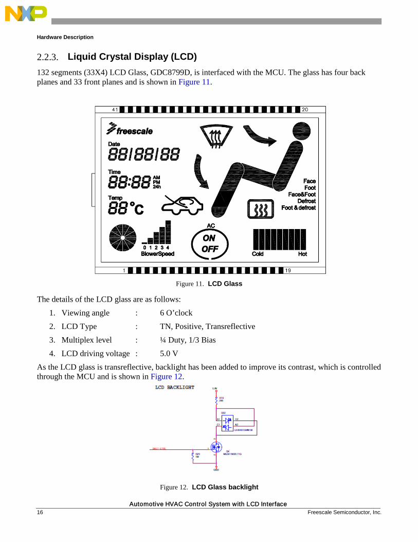
2.2.3. Liquid Crystal Display (LCD) 132 segments (33X4) LCD Glass, GDC8799D, is interfaced with the MCU. The glass has four back planes and 33 front planes and is shown in Figure 11.
Figure 11. LCD Glass
The details of the LCD glass are as follows:
1. Viewing angle : 6 O’clock
2. LCD Type : TN, Positive, Transreflective
3. Multiplex level : ¼ Duty, 1/3 Bias
4. LCD driving voltage : 5.0 V
As the LCD glass is transreflective, backlight has been added to improve its contrast, which is controlled through the MCU and is shown in Figure 12.
Figure 12. LCD Glass backlight
Hardware Description
Automotive HVAC Control System with LCD Interface Freescale Semiconductor, Inc. 17
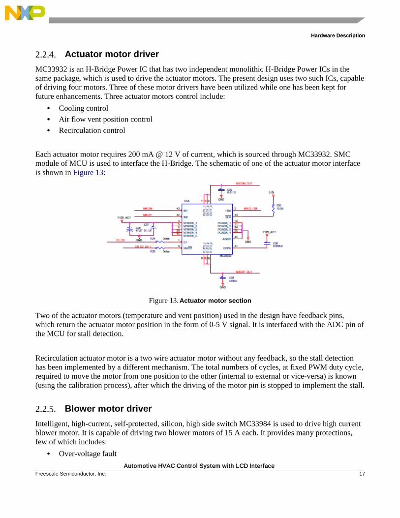
2.2.4. Actuator motor driver MC33932 is an H-Bridge Power IC that has two independent monolithic H-Bridge Power ICs in the same package, which is used to drive the actuator motors. The present design uses two such ICs, capable of driving four motors. Three of these motor drivers have been utilized while one has been kept for future enhancements. Three actuator motors control include:
• Cooling control • Air flow vent position control • Recirculation control
Each actuator motor requires 200 mA @ 12 V of current, which is sourced through MC33932. SMC module of MCU is used to interface the H-Bridge. The schematic of one of the actuator motor interface is shown in Figure 13:
Figure 13. Actuator motor section
Two of the actuator motors (temperature and vent position) used in the design have feedback pins, which return the actuator motor position in the form of 0-5 V signal. It is interfaced with the ADC pin of the MCU for stall detection. Recirculation actuator motor is a two wire actuator motor without any feedback, so the stall detection has been implemented by a different mechanism. The total numbers of cycles, at fixed PWM duty cycle, required to move the motor from one position to the other (internal to external or vice-versa) is known (using the calibration process), after which the driving of the motor pin is stopped to implement the stall.
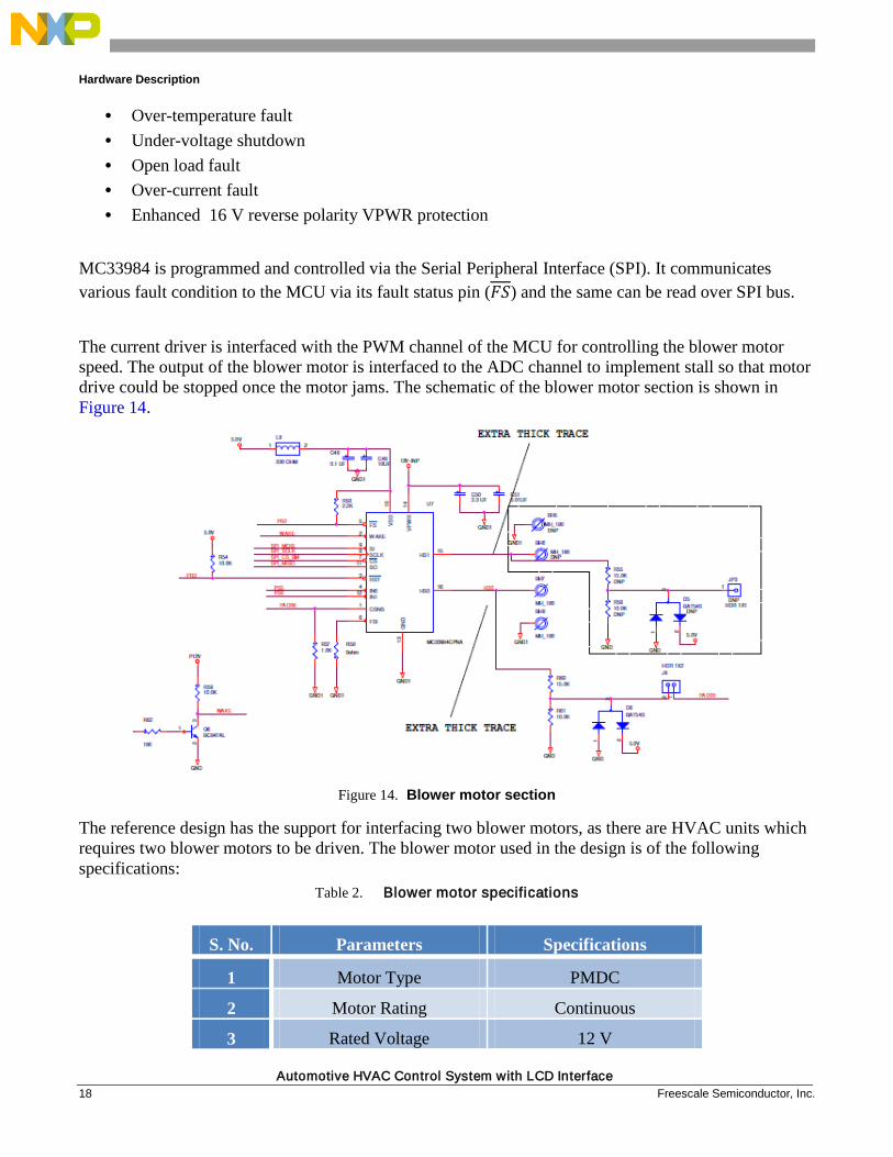
2.2.5. Blower motor driver Intelligent, high-current, self-protected, silicon, high side switch MC33984 is used to drive high current blower motor. It is capable of driving two blower motors of 15 A each. It provides many protections, few of which includes:
• Over-voltage fault
Hardware Description
Automotive HVAC Control System with LCD Interface 18 Freescale Semiconductor, Inc.
• Over-temperature fault • Under-voltage shutdown • Open load fault • Over-current fault • Enhanced 16 V reverse polarity VPWR protection
MC33984 is programmed and controlled via the Serial Peripheral Interface (SPI). It communicates various fault condition to the MCU via its fault status pin (𝐹𝑆) and the same can be read over SPI bus. The current driver is interfaced with the PWM channel of the MCU for controlling the blower motor speed. The output of the blower motor is interfaced to the ADC channel to implement stall so that motor drive could be stopped once the motor jams. The schematic of the blower motor section is shown in Figure 14.
Figure 14. Blower motor section
The reference design has the support for interfacing two blower motors, as there are HVAC units which requires two blower motors to be driven. The blower motor used in the design is of the following specifications:
Table 2. Blower motor specifications
S. No. Parameters Specifications
1 Motor Type PMDC
2 Motor Rating Continuous
3 Rated Voltage 12 V
Hardware Description
Automotive HVAC Control System with LCD Interface Freescale Semiconductor, Inc. 19
4 No Load Current 1.7 A
5 No Load Speed 4500 rpm
6 Rate Torque 0.3 Nm
7 Rated Current 14.5 A
8 Rated Speed 3600 ± 5%
9 Direction of Rotation CCW
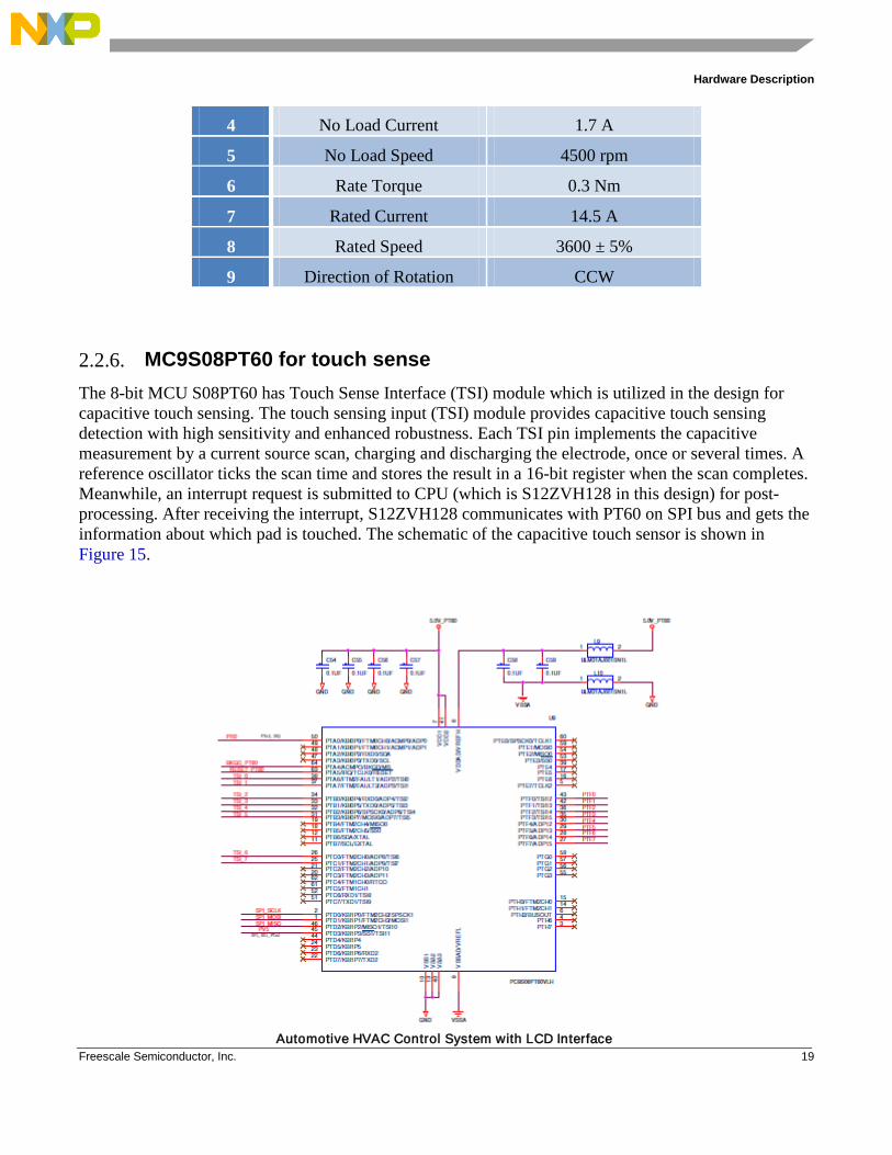
2.2.6. MC9S08PT60 for touch sense The 8-bit MCU S08PT60 has Touch Sense Interface (TSI) module which is utilized in the design for capacitive touch sensing. The touch sensing input (TSI) module provides capacitive touch sensing detection with high sensitivity and enhanced robustness. Each TSI pin implements the capacitive measurement by a current source scan, charging and discharging the electrode, once or several times. A reference oscillator ticks the scan time and stores the result in a 16-bit register when the scan completes. Meanwhile, an interrupt request is submitted to CPU (which is S12ZVH128 in this design) for post-processing. After receiving the interrupt, S12ZVH128 communicates with PT60 on SPI bus and gets the information about which pad is touched. The schematic of the capacitive touch sensor is shown in Figure 15.
Hardware Description
Automotive HVAC Control System with LCD Interface 20 Freescale Semiconductor, Inc.
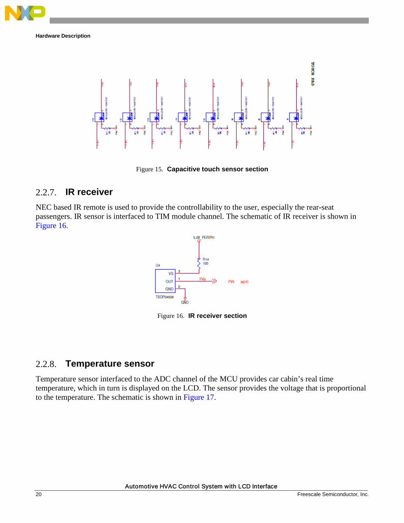
Figure 15. Capacitive touch sensor section
2.2.7. IR receiver NEC based IR remote is used to provide the controllability to the user, especially the rear-seat passengers. IR sensor is interfaced to TIM module channel. The schematic of IR receiver is shown in Figure 16.
Figure 16. IR receiver section
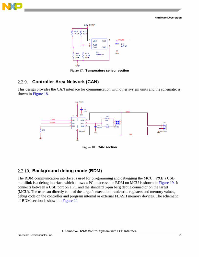
2.2.8. Temperature sensor Temperature sensor interfaced to the ADC channel of the MCU provides car cabin’s real time temperature, which in turn is displayed on the LCD. The sensor provides the voltage that is proportional to the temperature. The schematic is shown in Figure 17.
Hardware Description
Automotive HVAC Control System with LCD Interface Freescale Semiconductor, Inc. 21
Figure 17. Temperature sensor section
2.2.9. Controller Area Network (CAN) This design provides the CAN interface for communication with other system units and the schematic is shown in Figure 18.
Figure 18. CAN section
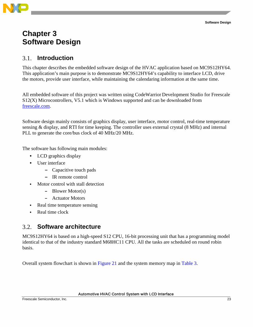
2.2.10. Background debug mode (BDM) The BDM communication interface is used for programming and debugging the MCU. P&E’s USB multilink is a debug interface which allows a PC to access the BDM on MCU is shown in Figure 19. It connects between a USB port on a PC and the standard 6-pin berg debug connector on the target (MCU). The user can directly control the target’s execution, read/write registers and memory values, debug code on the controller and program internal or external FLASH memory devices. The schematic of BDM section is shown in Figure 20
Automotive HVAC Control System with LCD Interface 22 Freescale Semiconductor, Inc.
Figure 19. PE micro USB multilink
Figure 20. Background debug section
Software Design
Automotive HVAC Control System with LCD Interface Freescale Semiconductor, Inc. 23
Chapter 3 Software Design
3.1. Introduction This chapter describes the embedded software design of the HVAC application based on MC9S12HY64. This application’s main purpose is to demonstrate MC9S12HY64’s capability to interface LCD, drive the motors, provide user interface, while maintaining the calendaring information at the same time. All embedded software of this project was written using CodeWarrior Development Studio for Freescale S12(X) Microcontrollers, V5.1 which is Windows supported and can be downloaded from freescale.com. Software design mainly consists of graphics display, user interface, motor control, real-time temperature sensing & display, and RTI for time keeping. The controller uses external crystal (8 MHz) and internal PLL to generate the core/bus clock of 40 MHz/20 MHz. The software has following main modules:
• LCD graphics display • User interface
— Capacitive touch pads — IR remote control
• Motor control with stall detection — Blower Motor(s) — Actuator Motors
• Real time temperature sensing • Real time clock
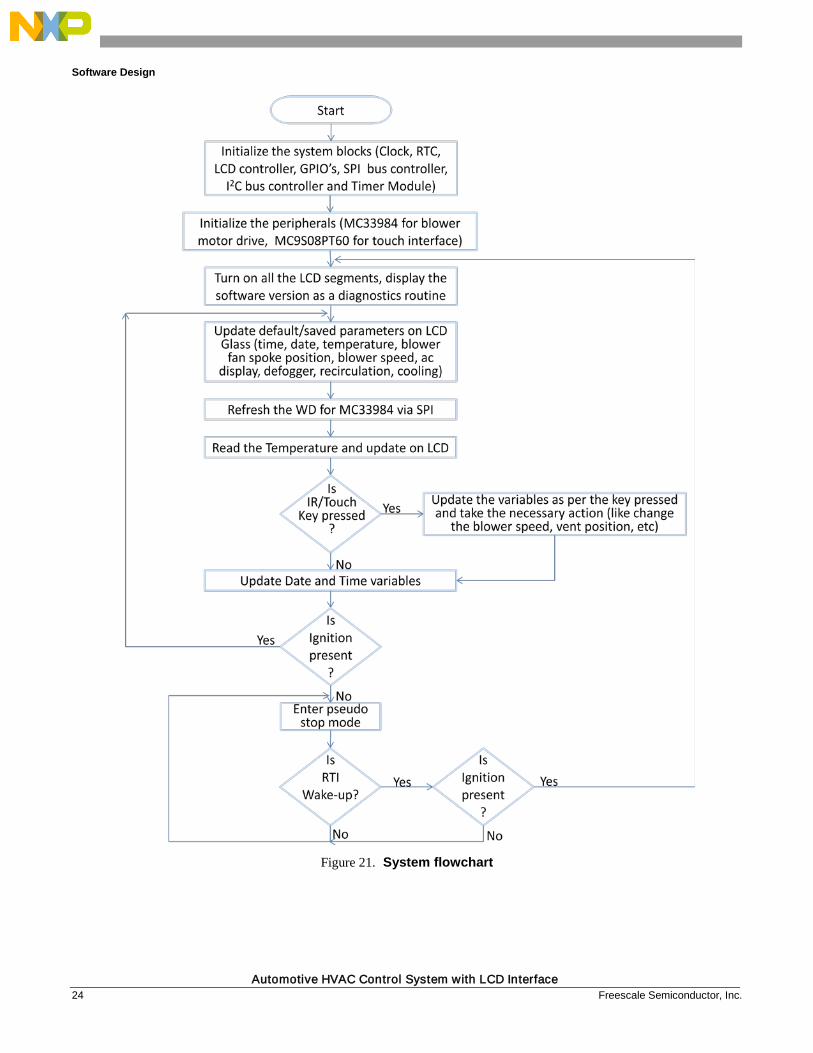
3.2. Software architecture MC9S12HY64 is based on a high-speed S12 CPU, 16-bit processing unit that has a programming model identical to that of the industry standard M68HC11 CPU. All the tasks are scheduled on round robin basis. Overall system flowchart is shown in Figure 21 and the system memory map in Table 3.
Software Design
Automotive HVAC Control System with LCD Interface 24 Freescale Semiconductor, Inc.
Figure 21. System flowchart
Software Design
Automotive HVAC Control System with LCD Interface Freescale Semiconductor, Inc. 25
Table 3. Memory map
Module Name Code Memory Data Memory
ADC 65 1
Actuator Motors 1,812 122
Blower Motor 538 13
Clock 30 0
IR Remote 727 17
LCD 8,245 27
Push Buttons 129 0
RTC 351 11
Temperature Sensor 80 6
Touch 250 1
Data Page 185 0
Main 2,513 27
Total 14,925 225
The following subsection describes each of the modules and its design flow.
3.2.1. LCD graphics display
Figure 22. LCD major blocks
Software Design
Automotive HVAC Control System with LCD Interface 26 Freescale Semiconductor, Inc.
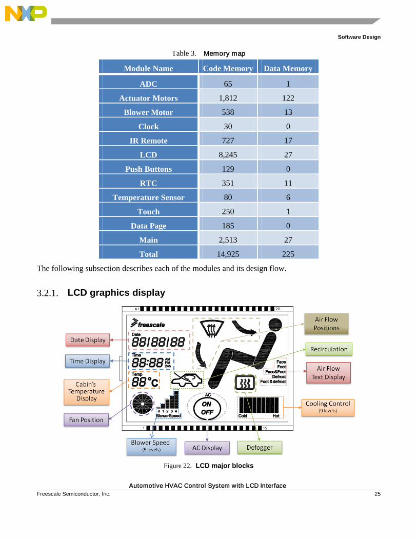
The existing HVAC units use mechanical knobs, which in the present design have been shown on LCD. Major blocks of LCD are shown in Figure 22, which include
• Date display – shows the date in DD/MM/YY format. • Time display – shows the Time in HH:MM format. User can select between 24H/12H display
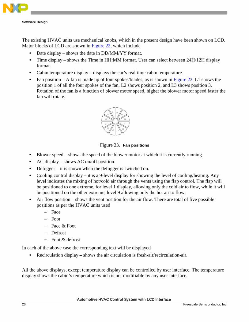
format. • Cabin temperature display – displays the car’s real time cabin temperature. • Fan position – A fan is made up of four spokes/blades, as is shown in Figure 23. L1 shows the
position 1 of all the four spokes of the fan, L2 shows position 2, and L3 shows position 3. Rotation of the fan is a function of blower motor speed, higher the blower motor speed faster the fan will rotate.
Figure 23. Fan positions
• Blower speed – shows the speed of the blower motor at which it is currently running. • AC display – shows AC on/off position. • Defogger – it is shown when the defogger is switched on. • Cooling control display – it is a 9-level display for showing the level of cooling/heating. Any
level indicates the mixing of hot/cold air through the vents using the flap control. The flap will be positioned to one extreme, for level 1 display, allowing only the cold air to flow, while it will be positioned on the other extreme, level 9 allowing only the hot air to flow.
• Air flow position – shows the vent position for the air flow. There are total of five possible positions as per the HVAC units used
— Face — Foot — Face & Foot — Defrost — Foot & defrost
In each of the above case the corresponding text will be displayed • Recirculation display – shows the air circulation is fresh-air/recirculation-air.
All the above displays, except temperature display can be controlled by user interface. The temperature display shows the cabin’s temperature which is not modifiable by any user interface.
Software Design
Automotive HVAC Control System with LCD Interface Freescale Semiconductor, Inc. 27
3.2.2. User interface The reference design has two types of interfaces:
1. IR remote control
2. Capacitive touch pads These will be discussed in detail in the following section.
3.2.2.1. IR remote control
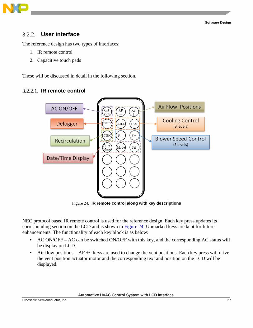
Figure 24. IR remote control along with key descriptions
NEC protocol based IR remote control is used for the reference design. Each key press updates its corresponding section on the LCD and is shown in Figure 24. Unmarked keys are kept for future enhancements. The functionality of each key block is as below:
• AC ON/OFF – AC can be switched ON/OFF with this key, and the corresponding AC status will be display on LCD.
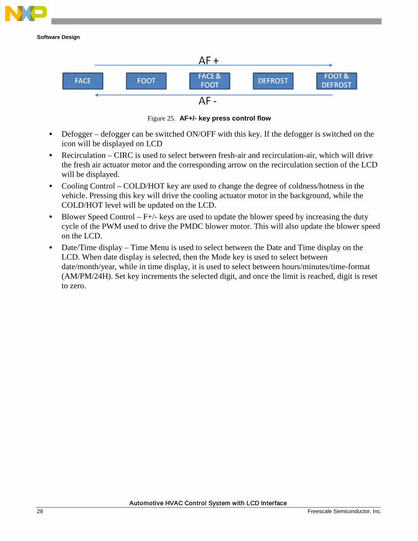
• Air flow positions – AF +/- keys are used to change the vent positions. Each key press will drive the vent position actuator motor and the corresponding text and position on the LCD will be displayed.
Software Design
Automotive HVAC Control System with LCD Interface 28 Freescale Semiconductor, Inc.
Figure 25. AF+/- key press control flow
• Defogger – defogger can be switched ON/OFF with this key. If the defogger is switched on the icon will be displayed on LCD
• Recirculation – CIRC is used to select between fresh-air and recirculation-air, which will drive the fresh air actuator motor and the corresponding arrow on the recirculation section of the LCD will be displayed.
• Cooling Control – COLD/HOT key are used to change the degree of coldness/hotness in the vehicle. Pressing this key will drive the cooling actuator motor in the background, while the COLD/HOT level will be updated on the LCD.
• Blower Speed Control – F+/- keys are used to update the blower speed by increasing the duty cycle of the PWM used to drive the PMDC blower motor. This will also update the blower speed on the LCD.
• Date/Time display – Time Menu is used to select between the Date and Time display on the LCD. When date display is selected, then the Mode key is used to select between date/month/year, while in time display, it is used to select between hours/minutes/time-format (AM/PM/24H). Set key increments the selected digit, and once the limit is reached, digit is reset to zero.
Software Design
Automotive HVAC Control System with LCD Interface Freescale Semiconductor, Inc. 29
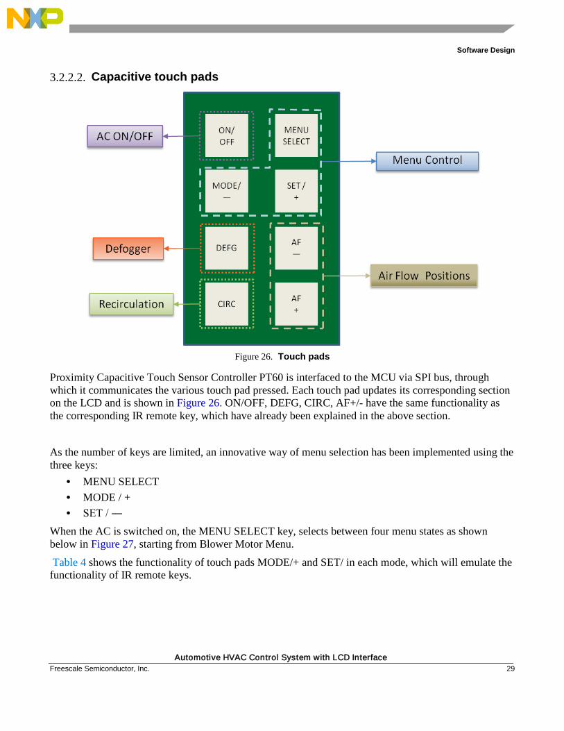
3.2.2.2. Capacitive touch pads
Figure 26. Touch pads
Proximity Capacitive Touch Sensor Controller PT60 is interfaced to the MCU via SPI bus, through which it communicates the various touch pad pressed. Each touch pad updates its corresponding section on the LCD and is shown in Figure 26. ON/OFF, DEFG, CIRC, AF+/- have the same functionality as the corresponding IR remote key, which have already been explained in the above section.
As the number of keys are limited, an innovative way of menu selection has been implemented using the three keys:
• MENU SELECT • MODE / + • SET / ―
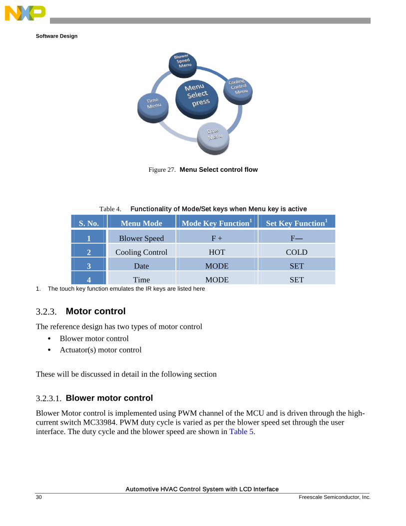
When the AC is switched on, the MENU SELECT key, selects between four menu states as shown below in Figure 27, starting from Blower Motor Menu.
Table 4 shows the functionality of touch pads MODE/+ and SET/ in each mode, which will emulate the functionality of IR remote keys.
Software Design
Automotive HVAC Control System with LCD Interface 30 Freescale Semiconductor, Inc.
Figure 27. Menu Select control flow
Table 4. Functionality of Mode/Set keys when Menu key is active
S. No. Menu Mode Mode Key Function1 Set Key Function1
1 Blower Speed F + F―
2 Cooling Control HOT COLD
3 Date MODE SET
4 Time MODE SET 1. The touch key function emulates the IR keys are listed here
3.2.3. Motor control The reference design has two types of motor control
• Blower motor control • Actuator(s) motor control
These will be discussed in detail in the following section
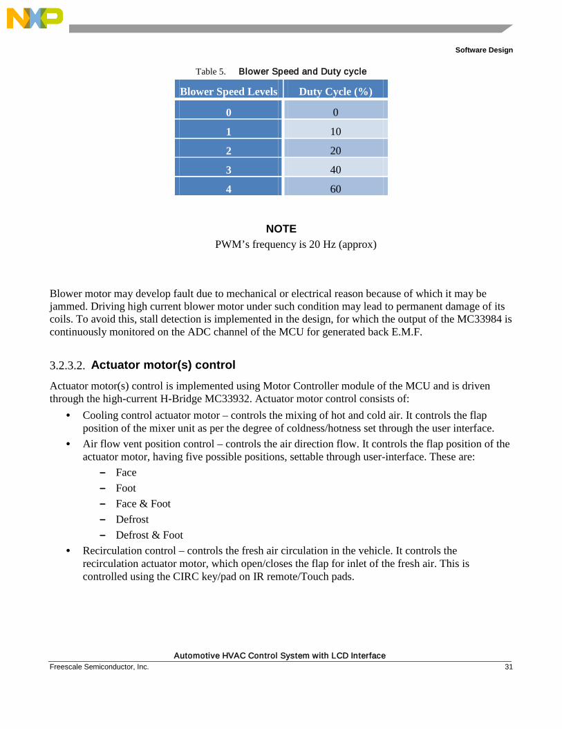
3.2.3.1. Blower motor control Blower Motor control is implemented using PWM channel of the MCU and is driven through the high-current switch MC33984. PWM duty cycle is varied as per the blower speed set through the user interface. The duty cycle and the blower speed are shown in Table 5.
Software Design
Automotive HVAC Control System with LCD Interface Freescale Semiconductor, Inc. 31
Table 5. Blower Speed and Duty cycle
Blower Speed Levels Duty Cycle (%)
0 0
1 10
2 20
3 40
4 60
NOTE PWM’s frequency is 20 Hz (approx)
Blower motor may develop fault due to mechanical or electrical reason because of which it may be jammed. Driving high current blower motor under such condition may lead to permanent damage of its coils. To avoid this, stall detection is implemented in the design, for which the output of the MC33984 is continuously monitored on the ADC channel of the MCU for generated back E.M.F.
3.2.3.2. Actuator motor(s) control Actuator motor(s) control is implemented using Motor Controller module of the MCU and is driven through the high-current H-Bridge MC33932. Actuator motor control consists of:
• Cooling control actuator motor – controls the mixing of hot and cold air. It controls the flap position of the mixer unit as per the degree of coldness/hotness set through the user interface.
• Air flow vent position control – controls the air direction flow. It controls the flap position of the actuator motor, having five possible positions, settable through user-interface. These are:
— Face — Foot — Face & Foot — Defrost — Defrost & Foot
• Recirculation control – controls the fresh air circulation in the vehicle. It controls the recirculation actuator motor, which open/closes the flap for inlet of the fresh air. This is controlled using the CIRC key/pad on IR remote/Touch pads.
Software Design
Automotive HVAC Control System with LCD Interface 32 Freescale Semiconductor, Inc.
3.2.4. Temperature sensor A temperature sensor has been interfaced with the MCU on the ADC channel, which is used to monitor the vehicle’s cabin temperature. The temperature is read continuously and the average temperature is shown on the LCD.
3.2.5. Real time clock The application integrates the Real time clock and calendaring information and displays it on the LCD; RTI is used for this purpose, which generates the interrupt periodically. In the reference design the periodicity of the interrupt is 250 ms. The application supports the setting of date and time through user interface. User can also select the time format as 24H/12H.
Testing and Measurements
Automotive HVAC Control System with LCD Interface Freescale Semiconductor, Inc. 33
Chapter 4 Testing and Measurements
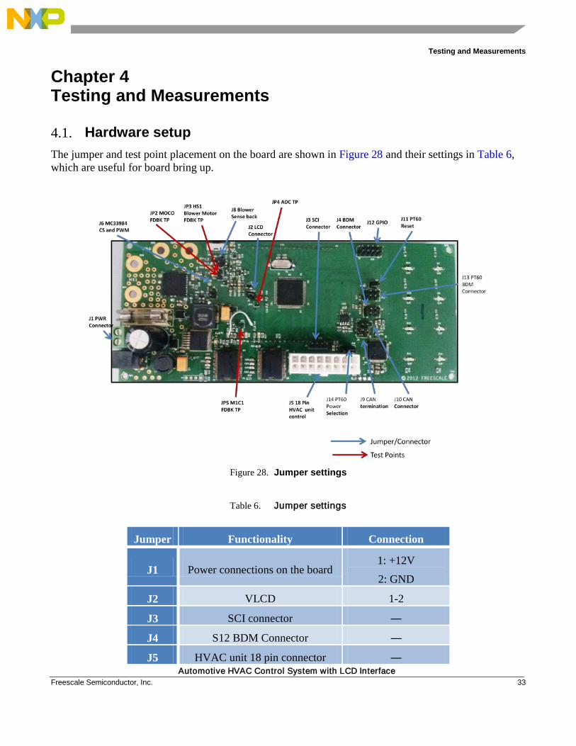
4.1. Hardware setup The jumper and test point placement on the board are shown in Figure 28 and their settings in Table 6, which are useful for board bring up.
Figure 28. Jumper settings
Table 6. Jumper settings
Jumper Functionality Connection
J1 Power connections on the board 1: +12V
2: GND
J2 VLCD 1-2
J3 SCI connector ―
J4 S12 BDM Connector ―
J5 HVAC unit 18 pin connector ―
Testing and Measurements
Automotive HVAC Control System with LCD Interface 34 Freescale Semiconductor, Inc.
J8 MC33984 Sense back
HS0 Blower motor feedback connected to ADC channel
―
J9 CAN termination connector ―
J10 CAN connector ―
J11 PT60 Reset Connector ―
J12 GPIO Connector ―
J13 PT60 BDM connector ―
J14 PT60 Power Selection Pin 2-3
4.2. Debugging and measurement In this section, waveforms are shown for each section.
4.2.1. LCD For testing the LCD, probe any of the frontplane pin, on which there is one ON segment. The waveform on such a pin will be as shown below:
Testing and Measurements
Automotive HVAC Control System with LCD Interface Freescale Semiconductor, Inc. 35
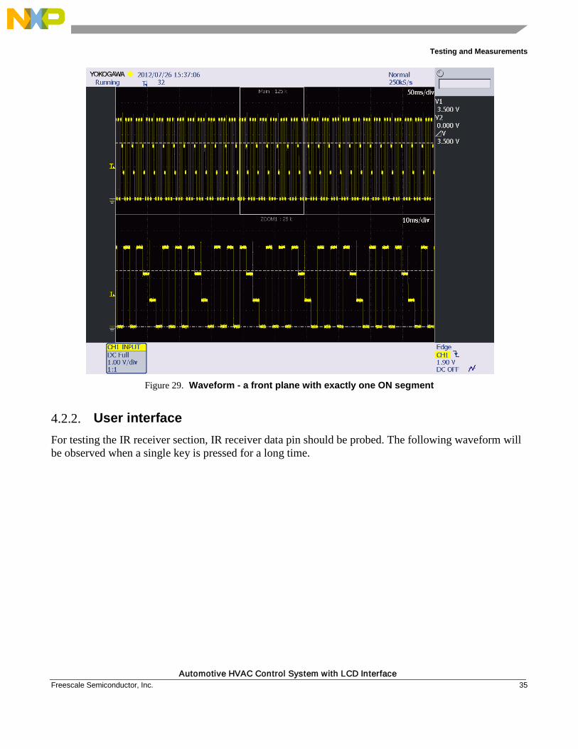
Figure 29. Waveform - a front plane with exactly one ON segment
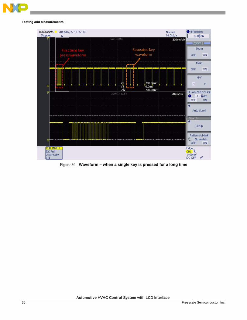
4.2.2. User interface For testing the IR receiver section, IR receiver data pin should be probed. The following waveform will be observed when a single key is pressed for a long time.
Testing and Measurements
Automotive HVAC Control System with LCD Interface 36 Freescale Semiconductor, Inc.
Figure 30. Waveform – when a single key is pressed for a long time
Testing and Measurements
Automotive HVAC Control System with LCD Interface Freescale Semiconductor, Inc. 37
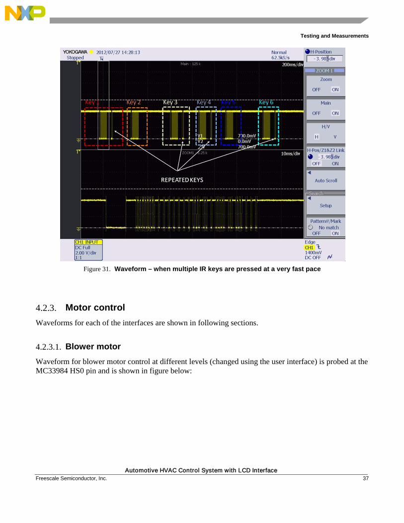
Figure 31. Waveform – when multiple IR keys are pressed at a very fast pace
4.2.3. Motor control Waveforms for each of the interfaces are shown in following sections.
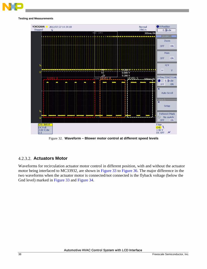
4.2.3.1. Blower motor Waveform for blower motor control at different levels (changed using the user interface) is probed at the MC33984 HS0 pin and is shown in figure below:
Testing and Measurements
Automotive HVAC Control System with LCD Interface 38 Freescale Semiconductor, Inc.
Figure 32. Waveform – Blower motor control at different speed levels
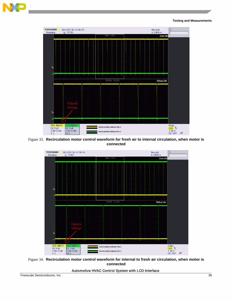
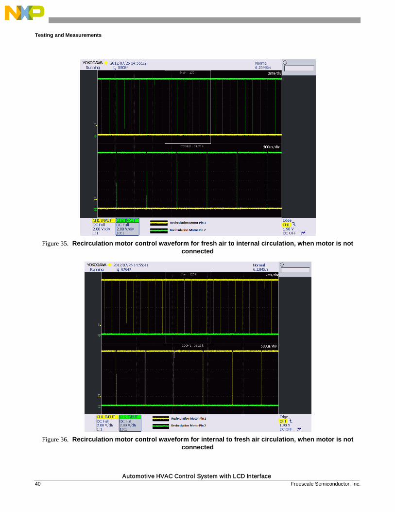
4.2.3.2. Actuators Motor Waveforms for recirculation actuator motor control in different position, with and without the actuator motor being interfaced to MC33932, are shown in Figure 33 to Figure 36. The major difference in the two waveforms when the actuator motor is connected/not connected is the flyback voltage (below the Gnd level) marked in Figure 33 and Figure 34.
Testing and Measurements
Automotive HVAC Control System with LCD Interface Freescale Semiconductor, Inc. 39
Figure 33. Recirculation motor control waveform for fresh air to internal circulation, when motor is
connected
Figure 34. Recirculation motor control waveform for internal to fresh air circulation, when motor is
connected
Testing and Measurements
Automotive HVAC Control System with LCD Interface 40 Freescale Semiconductor, Inc.
Figure 35. Recirculation motor control waveform for fresh air to internal circulation, when motor is not
connected
Figure 36. Recirculation motor control waveform for internal to fresh air circulation, when motor is not
connected
Testing and Measurements
Automotive HVAC Control System with LCD Interface Freescale Semiconductor, Inc. 41
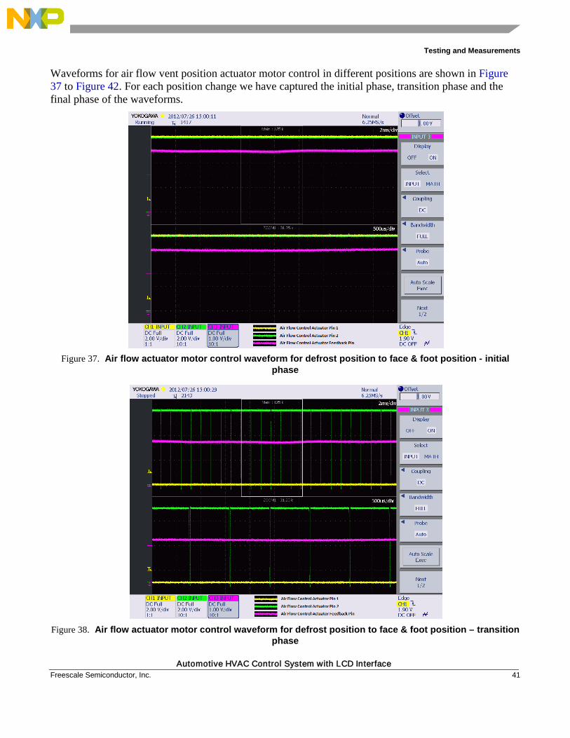
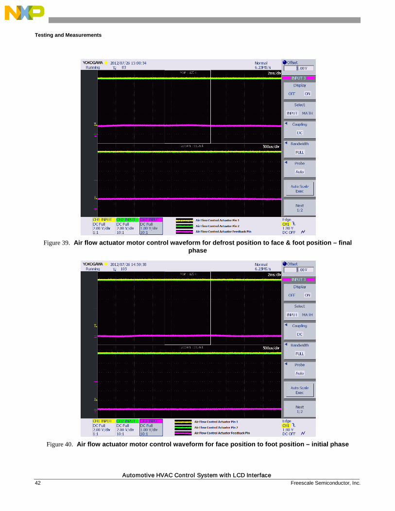
Waveforms for air flow vent position actuator motor control in different positions are shown in Figure 37 to Figure 42. For each position change we have captured the initial phase, transition phase and the final phase of the waveforms.
Figure 37. Air flow actuator motor control waveform for defrost position to face & foot position - initial
phase
Figure 38. Air flow actuator motor control waveform for defrost position to face & foot position – transition
phase
Testing and Measurements
Automotive HVAC Control System with LCD Interface 42 Freescale Semiconductor, Inc.
Figure 39. Air flow actuator motor control waveform for defrost position to face & foot position – final
phase
Figure 40. Air flow actuator motor control waveform for face position to foot position – initial phase
Testing and Measurements
Automotive HVAC Control System with LCD Interface Freescale Semiconductor, Inc. 43
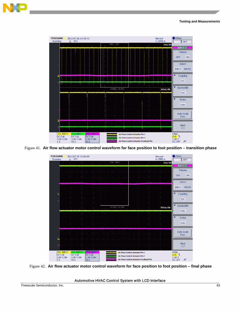
Figure 41. Air flow actuator motor control waveform for face position to foot position – transition phase
Figure 42. Air flow actuator motor control waveform for face position to foot position – final phase
Testing and Measurements
Automotive HVAC Control System with LCD Interface 44 Freescale Semiconductor, Inc.
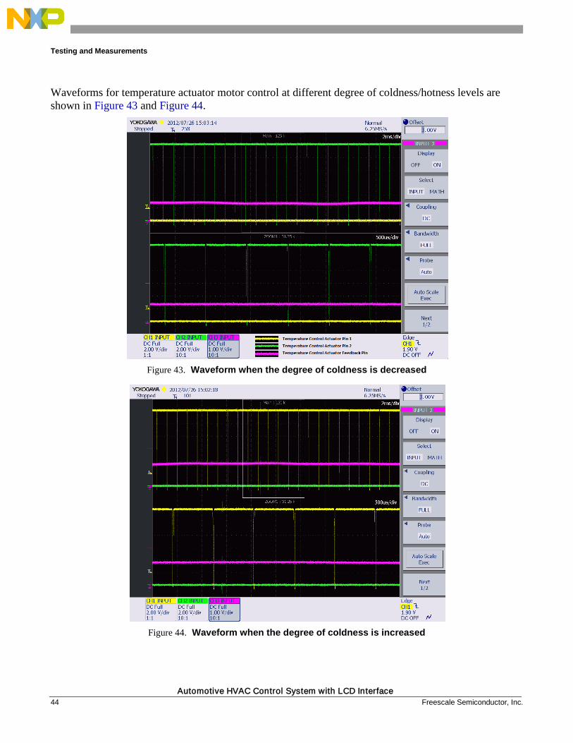
Waveforms for temperature actuator motor control at different degree of coldness/hotness levels are shown in Figure 43 and Figure 44.
Figure 43. Waveform when the degree of coldness is decreased
Figure 44. Waveform when the degree of coldness is increased

Testing and Measurements
Automotive HVAC Control System with LCD Interface Freescale Semiconductor, Inc. 45
4.3. Temperature sensor Waveform for the temperature sensor is shown in Figure 45 when the temperature on the sensor is increased. The waveform is captured by bringing the solder rod @ 200°C close to the sensor for 2 seconds (approx).
Figure 45. Waveform for temperature sensor output when temperature is increased drastically from the
ambient temperature
Testing and Measurements
Automotive HVAC Control System with LCD Interface 46 Freescale Semiconductor, Inc.
Appendix A
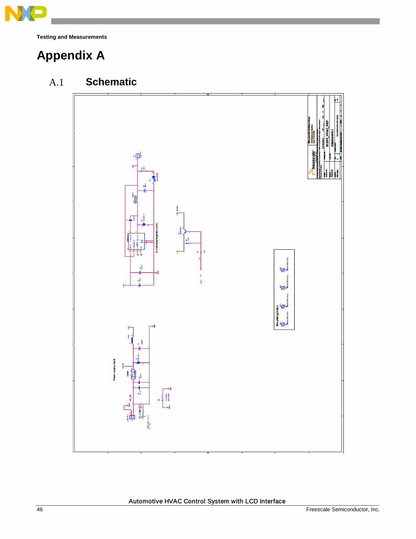
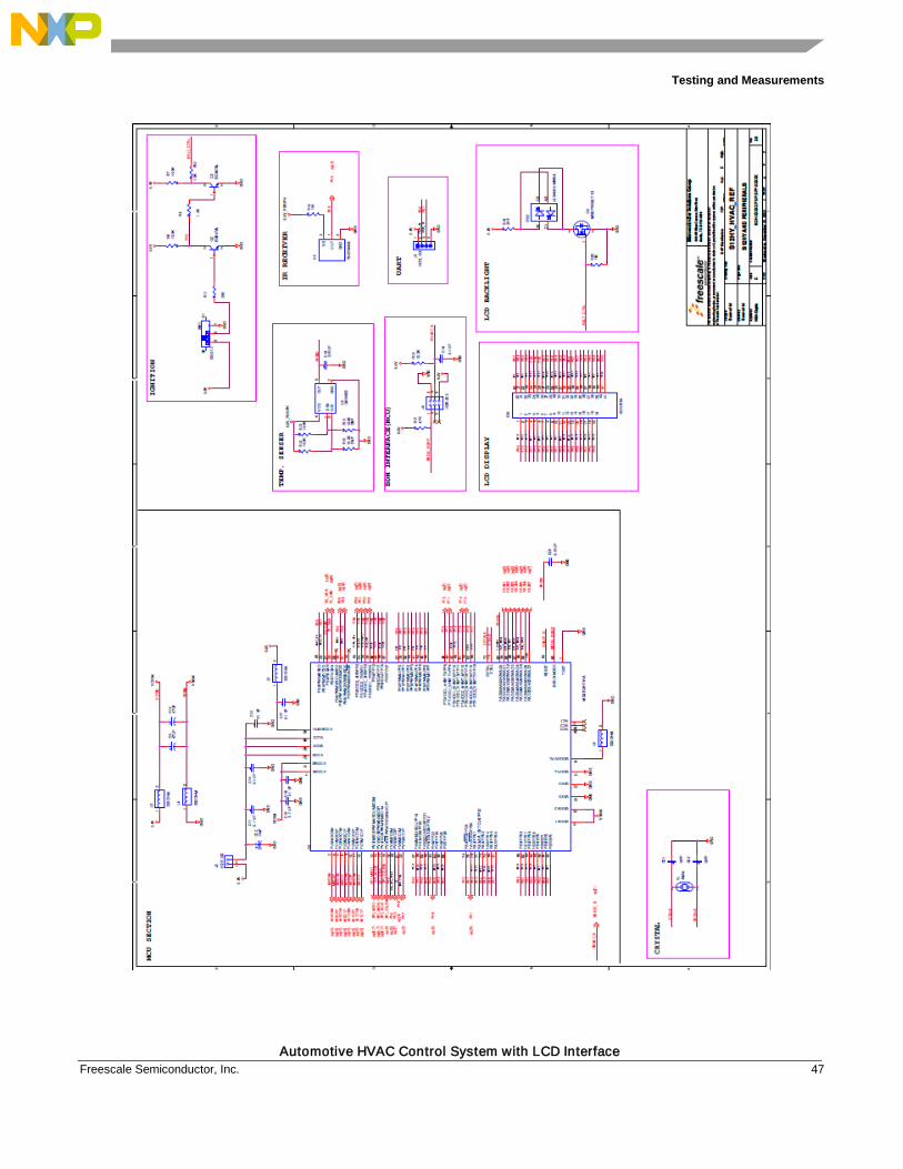
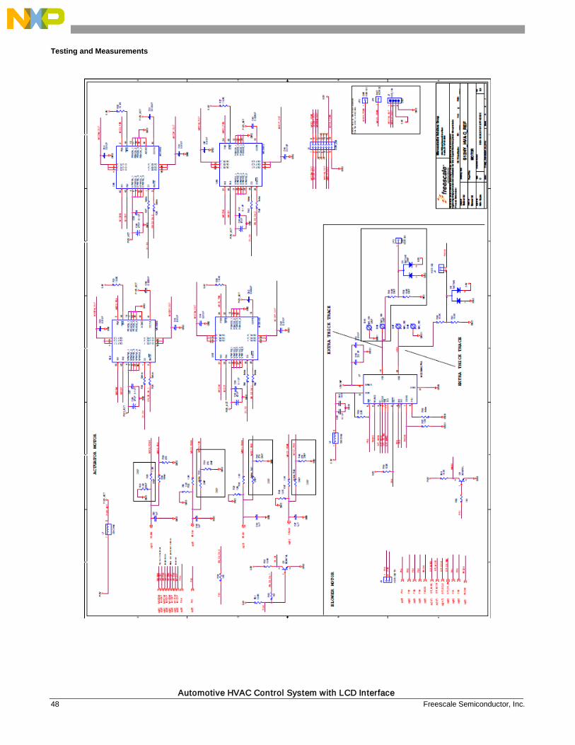
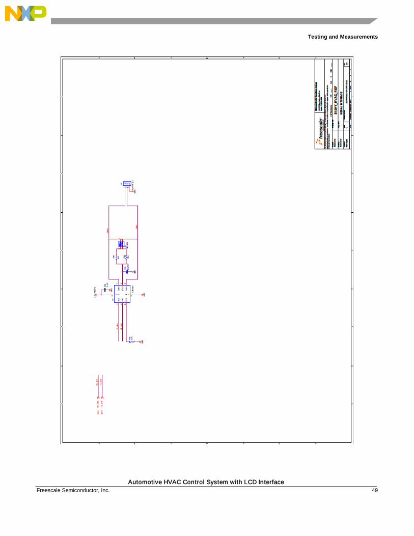
A.1 Schematic
Testing and Measurements
Automotive HVAC Control System with LCD Interface Freescale Semiconductor, Inc. 47
Testing and Measurements
Automotive HVAC Control System with LCD Interface 48 Freescale Semiconductor, Inc.
Testing and Measurements
Automotive HVAC Control System with LCD Interface Freescale Semiconductor, Inc. 49

Testing and Measurements
Automotive HVAC Control System with LCD Interface 50 Freescale Semiconductor, Inc.
Testing and Measurements
Automotive HVAC Control System with LCD Interface Freescale Semiconductor, Inc. 51
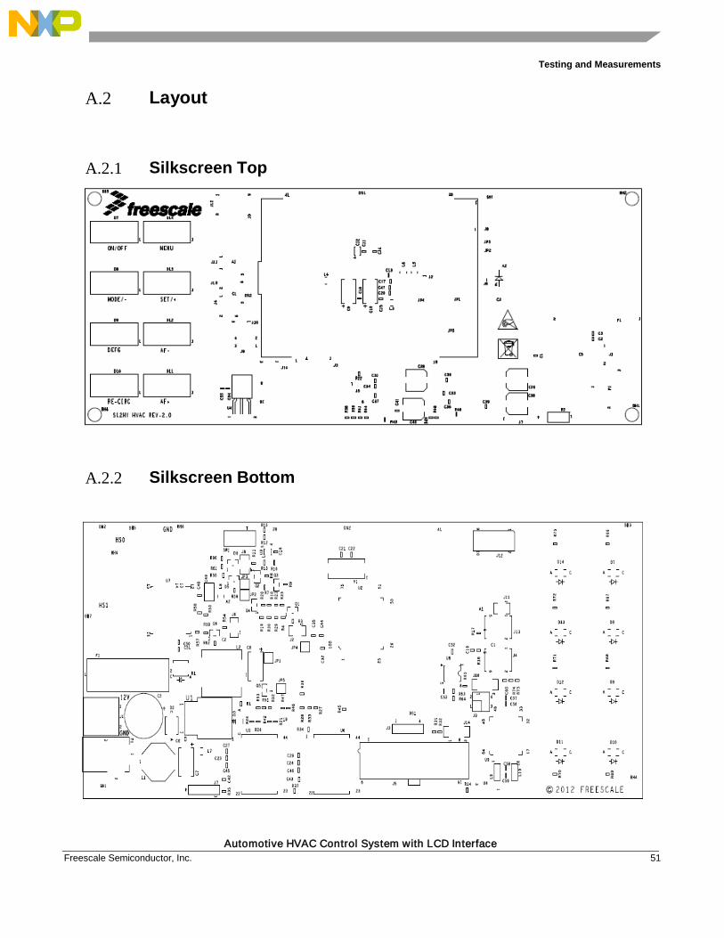
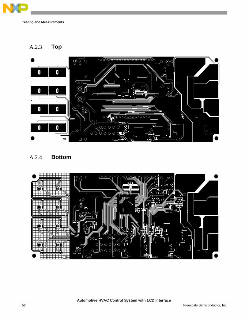
A.2 Layout
A.2.1 Silkscreen Top
A.2.2 Silkscreen Bottom
Testing and Measurements
Automotive HVAC Control System with LCD Interface 52 Freescale Semiconductor, Inc.
A.2.3 Top
A.2.4 Bottom

Testing and Measurements
Automotive HVAC Control System with LCD Interface Freescale Semiconductor, Inc. 53
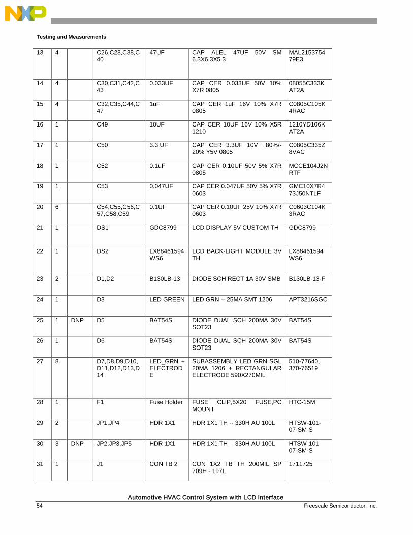
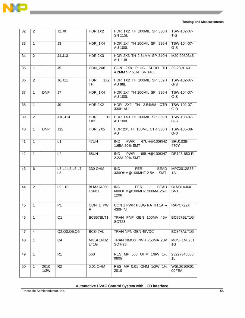
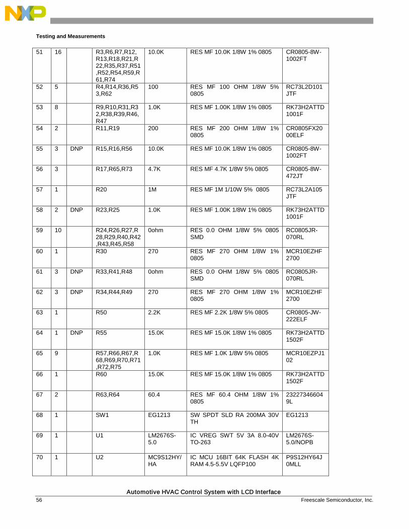
Appendix B Bill of Material Item
Quantity
ASSY_OPT
Reference Value Description Mfg Part Number
1 4 BH1,BH2,BH3,BH4
MOUNTING HOLE
MOUNTING HOLE DRILL 108 PAD 140 PLATED TH NO PART TO ORDER
Mounting Hole - 108mil Drill PTH
2 2 DNP BH5,BH6 MH_180 MOUNTING HOLE DRILL 135 PAD 180 PLATED TH NO PART TO ORDER
Mounting Hole - 135mil Drill PTH
3 2 BH7,BH8 MH_180 MOUNTING HOLE DRILL 135 PAD 180 PLATED TH NO PART TO ORDER
Mounting Hole - 135mil Drill PTH
4 12 C1,C18,C20,C23,C24,C33,C34,C36,C37,C45,C46,C51
0.01UF CAP CER 0.01UF 50V 10% X7R 0805
C0805X7R500-103KNE
5 15 C2,C6,C11,C13,C14,C15,C16,C17,C19,C27,C29,C39,C41,C48,C60
0.1 UF CAP CER 0.1UF 50V 10% X7R 0805
C0805C104K5RAC
6 1 C3 1000PF CAP CER 1000PF 50V 5% C0G 0805
C0805C0G500-102JNE
7 1 C5 1000UF CAP ALEL 1000UF 50V 20% -- RADIAL
UVZ1H102MHD
8 1 C7 10UF CAP TANT ESR=.125 OHMS 10UF 35V 10% 7343-31
TPSD106K035R0125
9 1 C8 68UF CAP TANT ESR=0.045 OHMS 68UF 25V 10% -- 7343-43
TPME686K025R0045
10 2 C9,C10 47UF CAP TANT 47UF 16V 10% -- 7343-31
293D476X9016D2TE3
11 1 C12 10uF CAP TANT 10uF 10V 10% -- 2013
T491R106K010AT
12 2 C21,C22 18PF CAP CER 18PF 50V 5% C0G 0805
08055A180JAT2A
Testing and Measurements
Automotive HVAC Control System with LCD Interface 54 Freescale Semiconductor, Inc.
13 4 C26,C28,C38,C40
47UF CAP ALEL 47UF 50V SM 6.3X6.3X5.3
MAL215375479E3
14 4 C30,C31,C42,C43
0.033UF CAP CER 0.033UF 50V 10% X7R 0805
08055C333KAT2A
15 4 C32,C35,C44,C47
1uF CAP CER 1uF 16V 10% X7R 0805
C0805C105K4RAC
16 1 C49 10UF CAP CER 10UF 16V 10% X5R 1210
1210YD106KAT2A
17 1 C50 3.3 UF CAP CER 3.3UF 10V +80%/-20% Y5V 0805
C0805C335Z8VAC
18 1 C52 0.1uF CAP CER 0.10UF 50V 5% X7R 0805
MCCE104J2NRTF
19 1 C53 0.047UF CAP CER 0.047UF 50V 5% X7R 0603
GMC10X7R473J50NTLF
20 6 C54,C55,C56,C57,C58,C59
0.1UF CAP CER 0.10UF 25V 10% X7R 0603
C0603C104K3RAC
21 1 DS1 GDC8799 LCD DISPLAY 5V CUSTOM TH GDC8799
22 1 DS2 LX88461594WS6
LCD BACK-LIGHT MODULE 3V TH
LX88461594WS6
23 2 D1,D2 B130LB-13 DIODE SCH RECT 1A 30V SMB B130LB-13-F
24 1 D3 LED GREEN LED GRN -- 25MA SMT 1206 APT3216SGC
25 1 DNP D5 BAT54S DIODE DUAL SCH 200MA 30V SOT23
BAT54S
26 1 D6 BAT54S DIODE DUAL SCH 200MA 30V SOT23
BAT54S
27 8 D7,D8,D9,D10,D11,D12,D13,D14
LED_GRN + ELECTRODE
SUBASSEMBLY LED GRN SGL 20MA 1206 + RECTANGULAR ELECTRODE 590X270MIL
510-77640, 370-76519
28 1 F1 Fuse Holder FUSE CLIP,5X20 FUSE,PC MOUNT
HTC-15M
29 2 JP1,JP4 HDR 1X1 HDR 1X1 TH -- 330H AU 100L HTSW-101-07-SM-S
30 3 DNP JP2,JP3,JP5 HDR 1X1 HDR 1X1 TH -- 330H AU 100L HTSW-101-07-SM-S
31 1 J1 CON TB 2 CON 1X2 TB TH 200MIL SP 709H - 197L
1711725
Testing and Measurements
Automotive HVAC Control System with LCD Interface Freescale Semiconductor, Inc. 55
32 2 J2,J8 HDR 1X2 HDR 1X2 TH 100MIL SP 330H SN 115L
TSW-102-07-T-S
33 1 J3 HDR_1X4 HDR 1X4 TH 100MIL SP 336H AU 100L
TSW-104-07-G-S
34 2 J4,J13 HDR 2X3 HDR 2X3 TH 2.54MM SP 340H AU 118L
M20-9980345
35 1 J5 CON_2X8 CON 2X8 PLUG SHRD TH 4.2MM SP 516H SN 140L
39-28-8160
36 2 J6,J11 HDR 1X2 TH
HDR 1X2 TH 100MIL SP 339H AU 98L
TSW-102-07-G-S
37 1 DNP J7 HDR_1X4 HDR 1X4 TH 100MIL SP 336H AU 100L
TSW-104-07-G-S
38 1 J9 HDR 2X2 HDR 2X2 TH 2.54MM CTR 330H AU
TSW-102-07-G-D
39 2 J10,J14 HDR TH 1X3
HDR 1X3 TH 100MIL SP 339H AU 100L
TSW-103-07-G-S
40 1 DNP J12 HDR_2X5 HDR 2X5 TH 100MIL CTR 330H AU
TSW-105-08-G-D
41 1 L1 47UH IND PWR 47UH@100KHZ 1.65A 30% SMT
SRU1038-470Y
42 1 L2 68UH IND PWR 68UH@100KHZ 2.22A 20% SMT
DR125-680-R
43 6 L3,L4,L5,L6,L7,L8
330 OHM IND FER BEAD 330OHM@100MHZ 2.5A -- SMT
MPZ2012S331A
44 2 L9,L10 BLM31AJ601SN1L
IND FER BEAD 600OHM@100MHZ 200MA 25% 1206
BLM31AJ601SN1L
45 1 P1 CON_1_PWR
CON 1 PWR PLUG RA TH 1A -- 430H NI
RAPC722X
46 1 Q1 BC857BLT1 TRAN PNP GEN 100MA 45V SOT23
BC857BLT1G
47 4 Q2,Q3,Q5,Q6 BC847AL TRAN NPN GEN 45VDC BC847ALT1G
48 1 Q4 MGSF1N02LT1G
TRAN NMOS PWR 750MA 20V SOT-23
MGSF1N02LT1G
49 1 R1 560 RES MF 560 OHM 1/8W 1% 0805
232273465601L
50 1 2010 1/2W
R2 0.01 OHM RES MF 0.01 OHM 1/2W 1% 2010
WSL2010R0100FEA
Testing and Measurements
Automotive HVAC Control System with LCD Interface 56 Freescale Semiconductor, Inc.
51 16 R3,R6,R7,R12,R13,R18,R21,R22,R35,R37,R51,R52,R54,R59,R61,R74
10.0K RES MF 10.0K 1/8W 1% 0805 CR0805-8W-1002FT
52 5 R4,R14,R36,R53,R62
100 RES MF 100 OHM 1/8W 5% 0805
RC73L2D101JTF
53 8 R9,R10,R31,R32,R38,R39,R46,R47
1.0K RES MF 1.00K 1/8W 1% 0805 RK73H2ATTD1001F
54 2 R11,R19 200 RES MF 200 OHM 1/8W 1% 0805
CR0805FX2000ELF
55 3 DNP R15,R16,R56 10.0K RES MF 10.0K 1/8W 1% 0805 CR0805-8W-1002FT
56 3 R17,R65,R73 4.7K RES MF 4.7K 1/8W 5% 0805 CR0805-8W-472JT
57 1 R20 1M RES MF 1M 1/10W 5% 0805 RC73L2A105JTF
58 2 DNP R23,R25 1.0K RES MF 1.00K 1/8W 1% 0805 RK73H2ATTD1001F
59 10 R24,R26,R27,R28,R29,R40,R42,R43,R45,R58
0ohm RES 0.0 OHM 1/8W 5% 0805 SMD
RC0805JR-070RL
60 1 R30 270 RES MF 270 OHM 1/8W 1% 0805
MCR10EZHF2700
61 3 DNP R33,R41,R48 0ohm RES 0.0 OHM 1/8W 5% 0805 SMD
RC0805JR-070RL
62 3 DNP R34,R44,R49 270 RES MF 270 OHM 1/8W 1% 0805
MCR10EZHF2700
63 1 R50 2.2K RES MF 2.2K 1/8W 5% 0805 CR0805-JW-222ELF
64 1 DNP R55 15.0K RES MF 15.0K 1/8W 1% 0805 RK73H2ATTD1502F
65 9 R57,R66,R67,R68,R69,R70,R71,R72,R75
1.0K RES MF 1.0K 1/8W 5% 0805 MCR10EZPJ102
66 1 R60 15.0K RES MF 15.0K 1/8W 1% 0805 RK73H2ATTD1502F
67 2 R63,R64 60.4 RES MF 60.4 OHM 1/8W 1% 0805
232273466049L
68 1 SW1 EG1213 SW SPDT SLD RA 200MA 30V TH
EG1213
69 1 U1 LM2676S-5.0
IC VREG SWT 5V 3A 8.0-40V TO-263
LM2676S-5.0/NOPB
70 1 U2 MC9S12HY/HA
IC MCU 16BIT 64K FLASH 4K RAM 4.5-5.5V LQFP100
P9S12HY64J0MLL
Testing and Measurements
Automotive HVAC Control System with LCD Interface Freescale Semiconductor, Inc. 57
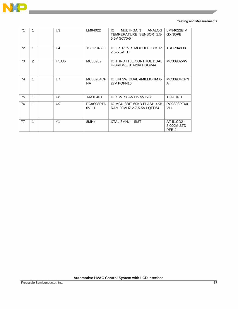
71 1 U3 LM94022 IC MULTI-GAIN ANALOG TEMPERATURE SENSOR 1.5-5.5V SC70-5
LM94022BIMGXNOPB
72 1 U4 TSOP34838 IC IR RCVR MODULE 38KHZ 2.5-5.5V TH
TSOP34838
73 2 U5,U6 MC33932 IC THROTTLE CONTROL DUAL H-BRIDGE 8.0-28V HSOP44
MC33932VW
74 1 U7 MC33984CPNA
IC LIN SW DUAL 4MILLIOHM 6-27V PQFN16
MC33984CPNA
75 1 U8 TJA1040T IC XCVR CAN HS 5V SO8 TJA1040T
76 1 U9 PC9S08PT60VLH
IC MCU 8BIT 60KB FLASH 4KB RAM 20MHZ 2.7-5.5V LQFP64
PC9S08PT60VLH
77 1 Y1 8MHz XTAL 8MHz -- SMT AT-51CD2-8.000M-STD-PFE-2
Document Number: DRM159
Rev 0 03/2015
How to Reach Us:
Home Page: freescale.com
Web Support: freescale.com/support
Information in this document is provided solely to enable system and software implementers to use Freescale products. There are no express or implied copyright licenses granted hereunder to design or fabricate any integrated circuits based on the information in this document.
Freescale reserves the right to make changes without further notice to any products herein. Freescale makes no warranty, representation, or guarantee regarding the suitability of its products for any particular purpose, nor does Freescale assume any liability arising out of the application or use of any product or circuit, and specifically disclaims any and all liability, including without limitation consequential or incidental damages. “Typical” parameters that may be provided in Freescale data sheets and/or specifications can and do vary in different applications, and actual performance may vary over time. All operating parameters, including “typicals,” must be validated for each customer application by customer's technical experts. Freescale does not convey any license under its patent rights nor the rights of others. Freescale sells products pursuant to standard terms and conditions of sale, which can be found at the following address: freescale.com/SalesTermsandConditions.
Freescale and the Freescale logo are trademarks of Freescale Semiconductor,Inc., Reg. U.S. Pat. & Tm. Off. All other product or service names are the property of their respective owners.
© 2015 Freescale Semiconductor, Inc.