DRIVING DATACENTER EFFICIENCY THROUGH...
50
DRIVING DATACENTER EFFICIENCY THROUGH SERVER AND APPLICATION CONSOLIDATION Virtualization for Sun SPARC Enterprise® M-Series Servers White Paper January 2009 Abstract The massive expansion of compute infrastructure over the last few decades have left many organizations facing power and cooling, floor space, and administrative challenges. By embracing application and server consolidation strategies, IT managers can gain real efficiencies that lower costs and streamline operations. Sun SPARC Enterprise® M-Series servers offer the scalability required to tackle consolidation projects. These systems also support a choice of virtualization technologies that help organizations match the right level of application and resource isolation to the job at hand.
Transcript of DRIVING DATACENTER EFFICIENCY THROUGH...
DRIVING DATACENTER EFFICIENCY THROUGH SERVER AND APPLICATION CONSOLIDATIONVirtualization for Sun SPARC Enterprise® M-Series Servers
White PaperJanuary 2009
Abstract
The massive expansion of compute infrastructure over the last few decades have left many organizations facing
power and cooling, floor space, and administrative challenges. By embracing application and server consolidation
strategies, IT managers can gain real efficiencies that lower costs and streamline operations. Sun SPARC
Enterprise® M-Series servers offer the scalability required to tackle consolidation projects. These systems also
support a choice of virtualization technologies that help organizations match the right level of application and
resource isolation to the job at hand.
Sun Microsystems, Inc.
Table of Contents
Executive Summary . . . . . . . . . . . . . . . . . . . . . . . . . . . . . . . . . . . . . . . . . . . . . . . . 1
Optimizing the Datacenter . . . . . . . . . . . . . . . . . . . . . . . . . . . . . . . . . . . . . . . . . . . 2
Server consolidation . . . . . . . . . . . . . . . . . . . . . . . . . . . . . . . . . . . . . . . . . . . . . . . . . . 3
Application consolidation . . . . . . . . . . . . . . . . . . . . . . . . . . . . . . . . . . . . . . . . . . . . . . 6
Putting it all to work . . . . . . . . . . . . . . . . . . . . . . . . . . . . . . . . . . . . . . . . . . . . . . . . . . 8
Improving Datacenter Efficiency and Flexibility . . . . . . . . . . . . . . . . . . . . . . . . . . 10
Dynamic Domains . . . . . . . . . . . . . . . . . . . . . . . . . . . . . . . . . . . . . . . . . . . . . . . . . . . 10
Dynamic Reconfiguration . . . . . . . . . . . . . . . . . . . . . . . . . . . . . . . . . . . . . . . . . . . . . 16
Capacity on Demand . . . . . . . . . . . . . . . . . . . . . . . . . . . . . . . . . . . . . . . . . . . . . . . . . 22
Simplifying Application Consolidation . . . . . . . . . . . . . . . . . . . . . . . . . . . . . . . . . 24
Solaris™ Containers technology. . . . . . . . . . . . . . . . . . . . . . . . . . . . . . . . . . . . . . . . . 24
Solaris Resource Manager software . . . . . . . . . . . . . . . . . . . . . . . . . . . . . . . . . . . . . 28
Managing the Virtualized Environment . . . . . . . . . . . . . . . . . . . . . . . . . . . . . . . . 33
eXtended system controller facility (XSCF) . . . . . . . . . . . . . . . . . . . . . . . . . . . . . . . . 33
Sun Management Center software . . . . . . . . . . . . . . . . . . . . . . . . . . . . . . . . . . . . . . 36
Solaris Management Console . . . . . . . . . . . . . . . . . . . . . . . . . . . . . . . . . . . . . . . . . . 44
SNMP service . . . . . . . . . . . . . . . . . . . . . . . . . . . . . . . . . . . . . . . . . . . . . . . . . . . . . . 45
Conclusion . . . . . . . . . . . . . . . . . . . . . . . . . . . . . . . . . . . . . . . . . . . . . . . . . . . . . . 47
References . . . . . . . . . . . . . . . . . . . . . . . . . . . . . . . . . . . . . . . . . . . . . . . . . . . . . . . . 47
1 Executive Summary Sun Microsystems, Inc.
Executive Summary
Business processes are increasingly dependent upon technology. After decades of
expanding the IT infrastructure, many organizations own a large, complex network of
systems. Current challenges within these environments include datacenter floor space
limits, excessive energy costs, and constraints on administrative resources. Given these
conditions, many IT managers seek a more reasonable IT infrastructure strategy.
Opportunities exist to gain efficiencies through application and server consolidation.
Bringing together applications, databases, and services onto fewer, highly reliable
servers can lower costs, increase efficiency, and reduce administration requirements.
Sun SPARC Enterprise® M-Series servers offer the scalability that can maximize the
return on consolidation efforts. In addition, these systems provide a range of
virtualization technologies — at no additional cost — that can help companies achieve
the right level of application isolation and management flexibility.
With symmetric multiprocessing scalability from 1 to 64 processors, memory
subsystems as large as 2 TB, and high-throughput I/O architectures, Sun SPARC
Enterprise M-Series servers easily perform the heavy lifting required of consolidated
workloads. Also architected to reduce planned and unplanned downtime, these servers
provide the increased reliability, availability, and serviceability needed by consolidated
IT infrastructure. Sun SPARC Enterprise M-Series servers support a variety of tools to
create a virtualized environment and simplify management of application and resource
isolation, including the following:
• Dynamic Domains partition Sun SPARC Enterprise M-Series servers along physical
boundaries, providing complete resource isolation between applications.
• Dynamic Reconfiguration helps support continuous uptime and increases flexibility
by allowing the addition and removal of CPU/memory and I/O boards and transfer of
these resources from one Dynamic Domain to another without interrupting
application processing.
• Solaris Containers technology isolates software applications and services using
flexible, software-defined boundaries. With this technology many private execution
environments can be created within a single instance of the Solaris™ Operating
System (OS).
Through examples, this document provides insight to the virtualization capabilities
provided by Sun SPARC Enterprise M-Series servers. Detailed descriptions of Dynamic
Domains, Dynamic Reconfiguration, and Solaris Containers technologies help provide a
better understanding of each virtualization tool. In addition, information is included
regarding embedded and add-on management tools that help streamline operation
and enhance the value of utilizing Sun SPARC Enterprise M-Series servers within a
virtualization strategy.
2 Optimizing the Datacenter Sun Microsystems, Inc.
Chapter 1
Optimizing the Datacenter
Datacenters containing a large number of out-dated and under-utilized servers are
cumbersome to manage and expensive to maintain. By reducing server count,
consolidation projects can help organizations realize greater efficiency. An environment
with fewer systems lowers datacenter space, power, and cooling requirements and
reduces administrative tasks. Consolidating applications and servers can also reduce
software licensing, support, and maintenance fees. As a result, companies can achieve
significant capital and operating cost reductions. Furthermore, moving software that
executes on older hardware and operating systems onto new, more powerful platforms
often provides the side benefit of improving application performance.
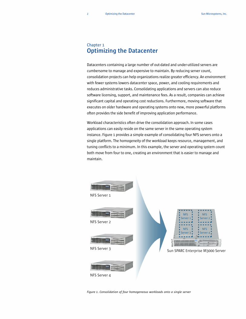
Workload characteristics often drive the consolidation approach. In some cases
applications can easily reside on the same server in the same operating system
instance. Figure 1 provides a simple example of consolidating four NFS servers onto a
single platform. The homogeneity of the workload keeps resource, management, and
tuning conflicts to a minimum. In this example, the server and operating system count
both move from four to one, creating an environment that is easier to manage and
maintain.
Figure 1. Consolidation of four homogeneous workloads onto a single server
NFS Server 1
Sun SPARC Enterprise M3000 Server
NFS Server 1
NFS Server 2
NFS Server 3
NFS Server 4
NFS Server 2
NFS Server 3
NFS Server 4
3 Optimizing the Datacenter Sun Microsystems, Inc.
In contrast to this first example, most consolidation projects are more complex and
involve the co-location of multiple types of workloads. Within many IT departments,
early attempts to host a mix of applications on a single server uncovered a number of
challenges. For instance, an ill-behaved application can starve the processing or I/O
resources from other co-located software. Maintenance and tuning requirements might
not always align easily. In addition, simply installing a number of applications on a
single server can fail to provide the strict boundaries required by applications that
process sensitive data. In the past, finding compatible workloads meant creating
detailed application profiles, including operating system tuning needs, software library
requirements, uptime mandates, and growth predictions. At the end of these efforts,
many organizations failed to identify more than a few application consolidation
opportunities. Many applications simply required the isolation previously only available
by executing them on a separate server.
Today, a number of approaches exist to help isolate software programs running within
a consolidated server. As described in the following sections, Sun SPARC Enterprise® M-Series servers support a range of technologies to accommodate various flexibility,
availability, and security requirements.
Server consolidationServer consolidation projects aim at reducing the total number of systems in the
datacenter. The security and workload characteristics of some applications can
complicate server consolidation efforts. However, hard partitioning technology can
simplify the process of reducing the total number of systems while still maintaining
complete application isolation. Hard partitioning technology divides the physical
resources of a system, providing individual workloads with exclusive access to specific
CPU, memory, and I/O components.
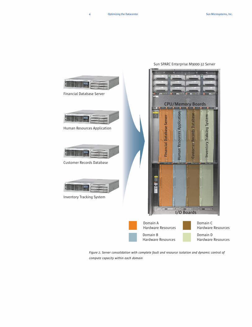
Sun SPARC Enterprise M-Series servers offer hard partitioning technology in the form of
Dynamic Domains. Instantiating a number of Dynamic Domains on a Sun SPARC
Enterprise M-Series server divides the system into multiple electrically isolated
partitions. Each Dynamic Domain executes a unique instance of the Solaris OS. Since
isolation is instantiated all the way to the hardware, configurations can be created in
which software changes, reboots, and potential faults in one domain do not impact
applications running in other domains. Figure 2 provides an example of consolidating a
number of resource intensive applications with various security and uptime
requirements onto a single platform.
4 Optimizing the Datacenter Sun Microsystems, Inc.
Figure 2. Server consolidation with complete fault and resource isolation and dynamic control of
compute capacity within each domain
Domain AHardware Resources
Domain B Hardware Resources
Domain CHardware Resources
Domain D Hardware Resources
Sun SPARC Enterprise M9000-32 Server
CPU/Memory Boards
I/O Boards
Financial Database Server
Human Resources Application
Customer Records Database
Inventory Tracking System
Hu
man
Res
ourc
es A
pplic
atio
n
Cust
omer
Rec
ords
Dat
abas
e
Fin
anci
al D
atab
ase
Serv
er
Inve
nto
ry T
rakc
ing
Syst
em
5 Optimizing the Datacenter Sun Microsystems, Inc.
A feature of Sun SPARC Enterprise M-Series servers known as Dynamic Reconfiguration
(DR) supports the movement of CPU, memory, and I/O resources from one Dynamic
Domain to another — without the need for downtime. As described in the following
examples, utilizing Dynamic Domains and DR can help organizations respond more
rapidly to changing business conditions and project requirements:
• Consolidation — One Sun SPARC Enterprise M-Series server can replace multiple
smaller servers. Consolidated servers are easier to administer, more robust, and offer
the flexibility to shift resources freely from one application to another. Increased
flexibility is especially important as applications grow, or when demand reaches peak
levels, requiring additional resources to be rapidly deployed.
• Development, production, and test environments — In production environments
many sites require separate development and test systems. Isolating these systems
with domains helps enable development work to continue without impacting
production runs. With the Sun SPARC Enterprise M-Series servers, development and
test functions can safely coexist on the same platform.
• Software migration — Dynamic Domains can be used to help migrate systems or
application software and associated users to updated versions. New, or perhaps
more experienced users can employ the latest versions in one isolated domain, while
others waiting to be trained can continue to use older versions in another domain.
This approach applies equally well to the Solaris OS, database applications, new
administrative environments, and other applications.
• Special I/O or network functions — A system domain can be established to deal with
specific I/O devices or functions isolated within its domain. For example, a high-end
tape device can be attached to a dedicated system domain, which can be added to
other system domains when there is a need to make use of the device.
• Departmental systems — Multiple projects or departments can share a single Sun
SPARC Enterprise M-Series server, increasing economies of scale and easing cost
justification and accounting requirements.
• Configuring for special resource requirements or limitations — Projects that have
resource requirements that might starve other applications can be isolated to their
own system domain. For applications that lack scalability, multiple instances of the
application can be run in separate system domains, or in containers within one
domain.
• Hardware repairs and rolling upgrades — Because each domain runs its own
instance of the Solaris OS and has its own peripherals and network connections,
domains can be reconfigured without interrupting the operation of other domains.
Domains can be used to remove and reinstall boards for repair or upgrade, to test
new applications, and to perform operating system updates.
6 Optimizing the Datacenter Sun Microsystems, Inc.
Taking advantage of Dynamic Domains can help organizations reduce the number of
datacenter platforms while dramatically increasing the flexibility of the capacity
planning and management process. More information on the hard partitioning
capabilities of Sun SPARC Enterprise M-Series servers is contained in “Improving
Datacenter Efficiency and Flexibility” on page 10.
Application consolidationMinimizing operating costs is a common goal of consolidation projects. For many
organizations, this aim requires application consolidation — reducing the number of
operating system instances and applications in addition to the number of platforms.
Ideally, application consolidation merges the functions of multiple software programs
into a single workload. At the least, application consolidation involves hosting more
than one software program per operating system instance.
Resource contention between applications and conflicting software settings can
become an obstacle to application consolidation. Operating system virtualization
technology can help create isolated environments, allowing multiple applications to
coexist without interference. Sun SPARC Enterprise M-Series servers support Solaris
Containers technology to facilitate provisioning the compute resources of a single
server and operating system instance into many private execution environments.
Within Solaris Containers, Zone s are the virtual operating system abstractions that
control namespace and software fault isolation. Each Zone maintains a unique identity
that is separate from the underlying hardware and behaves as if it is a single system.
Solaris Resource Manager software is an additional component of a Solaris Container
that further defines resource rights. Solaris Resource Manager software leverages
operating system controls to govern utilization of CPU, memory, and I/O. For example,
system administrators can set and enforce policies that guarantee a share of CPU cycles
and virtual memory space to individual Zones. Administrators can also set upper limits
on process count, number of logins, and connect time for each system user ID. To
increase flexibility, Solaris Resource Manager software supports dynamic allocation of
processors and individual processor cores to a Solaris Container.
Solaris Containers enable organizations to:
• Build customized, isolated environments — each with its own IP address, file system,
users, and assigned resources — to safely and easily consolidate systems
• Guarantee sufficient CPU and memory resource allocation to applications while
retaining the ability to use idle resources as needed
• Reserve and allocate a specific CPU or group of CPUs for the exclusive use of the
container
7 Optimizing the Datacenter Sun Microsystems, Inc.
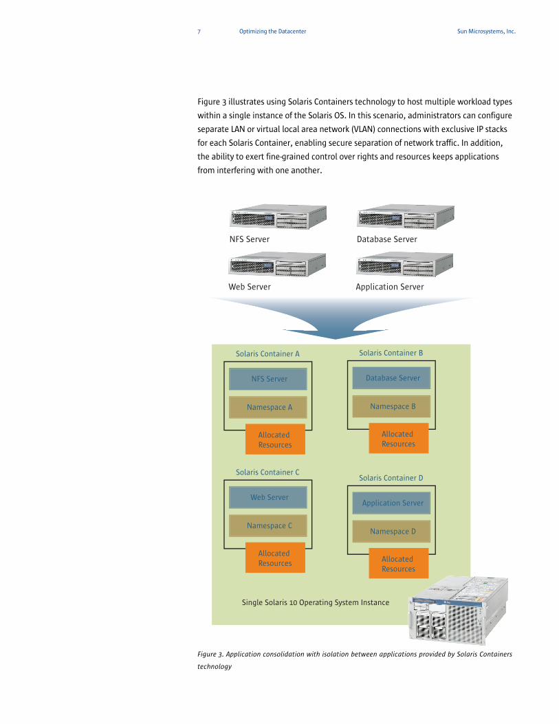
Figure 3 illustrates using Solaris Containers technology to host multiple workload types
within a single instance of the Solaris OS. In this scenario, administrators can configure
separate LAN or virtual local area network (VLAN) connections with exclusive IP stacks
for each Solaris Container, enabling secure separation of network traffic. In addition,
the ability to exert fine-grained control over rights and resources keeps applications
from interfering with one another.
Figure 3. Application consolidation with isolation between applications provided by Solaris Containers
technology
Single Solaris 10 Operating System Instance
Solaris Container A
NFS Server
Namespace A
Allocated Resources
Solaris Container B
Database Server
Namespace B
Allocated Resources
Solaris Container C
Web Server
Namespace C
Allocated Resources
Solaris Container D
Application Server
Namespace D
Allocated Resources
NFS Server Database Server
Web Server Application Server
8 Optimizing the Datacenter Sun Microsystems, Inc.
Utilizing Solaris Containers technology can help organizations create consolidated
environments that dramatically decrease the number of operating system instances to
manage. Additional information on utilizing Solaris Containers technology with Sun
SPARC Enterprise M-Series servers is contained in “Simplifying Application
Consolidation” on page 24.
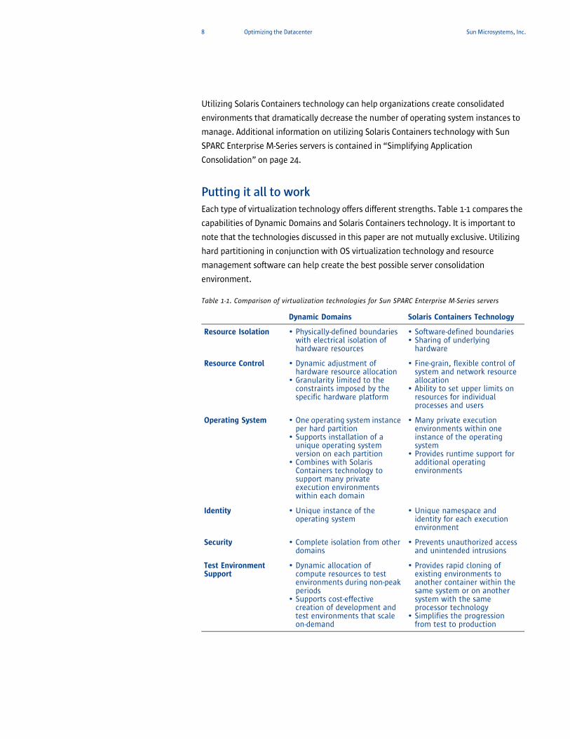
Putting it all to workEach type of virtualization technology offers different strengths. Table 1-1 compares the
capabilities of Dynamic Domains and Solaris Containers technology. It is important to
note that the technologies discussed in this paper are not mutually exclusive. Utilizing
hard partitioning in conjunction with OS virtualization technology and resource
management software can help create the best possible server consolidation
environment.
Table 1-1. Comparison of virtualization technologies for Sun SPARC Enterprise M-Series servers
Dynamic Domains Solaris Containers Technology
Resource Isolation • Physically-defined boundaries with electrical isolation of hardware resources
• Software-defined boundaries• Sharing of underlying
hardware
Resource Control • Dynamic adjustment of hardware resource allocation
• Granularity limited to the constraints imposed by the specific hardware platform
• Fine-grain, flexible control of system and network resource allocation
• Ability to set upper limits on resources for individual processes and users
Operating System • One operating system instance per hard partition
• Supports installation of a unique operating system version on each partition
• Combines with Solaris Containers technology to support many private execution environments within each domain
• Many private execution environments within one instance of the operating system
• Provides runtime support for additional operating environments
Identity • Unique instance of the operating system
• Unique namespace and identity for each execution environment
Security • Complete isolation from other domains
• Prevents unauthorized access and unintended intrusions
Test Environment Support
• Dynamic allocation of compute resources to test environments during non-peak periods
• Supports cost-effective creation of development and test environments that scale on-demand
• Provides rapid cloning of existing environments to another container within the same system or on another system with the same processor technology
• Simplifies the progression from test to production
9 Optimizing the Datacenter Sun Microsystems, Inc.
Sun SPARC Enterprise M-Series servers deliver the technology to help organizations
create an ideal consolidation environment. For example, multiple Solaris Zones that
implement Solaris Resource Manager software controls can be established within each
Dynamic Domain on a Sun SPARC Enterprise M-Series server to create the following
advantages:
• Applications that must remain physically isolated from one another or require
different versions of the operating system can be placed in separate domains.
• Compute resources can be added and removed from Dynamic Domains on-demand to
maximize system utilization.
• By utilizing Solaris Containers technology, multiple applications can reside within a
single domain, reducing the number of operating system instances to manage while
minimizing application conflicts.
• Solaris Resource Manager software can govern proper distribution of resources
within a given Solaris Container, helping avoid the potential for one application to
starve another software program of compute power.
10 Improving Datacenter Efficiency and Flexibility Sun Microsystems, Inc.
Chapter 2
Improving Datacenter Efficiency and Flexibility
Given the increasing need for non-stop availability of IT services, organizations often
demand Service Level Agreements (SLAs). These contracts define the services to be
provided along with metrics for determining if they have been adequately delivered.
Hosting each project or application with a dedicated system can help meet SLA
agreements. However, this approach often creates a proliferation of systems,
increasing administration tasks and costs and creating an inflexible, inefficient
environment. Consolidating workloads on to fewer, more powerful servers can foster
greater efficiency.
Sun SPARC Enterprise M-Series servers offer powerful features to partition the system’s
resources into isolated domains. The assignment of resources to individual domains
can be dynamically adjusted to meet changing demands. For example, a single Sun
SPARC Enterprise M-Series server, partitioned into domains, each running an instance
of the Solaris OS, can support many applications, including:
• File and print services for heterogeneous clients
• Messaging and mail services
• Web services
• Application services
• Mission-critical databases, data warehouses, and analytics
Dynamic DomainsTwo key technologies Sun SPARC Enterprise M-Series servers offer to enable
consolidation are Dynamic Domains and Dynamic Reconfiguration (DR). Through the
power of DR — an enabling technology behind Dynamic Domains — system resources
can be added and removed from individual domains without impacting operation. This
capability can lead to more flexible and cost-effective management of IT resources.
A domain is an independent system resource that runs its own copy of the Solaris OS.
Domains divide a system’s total resources into separate units that are not affected by
each other’s operations. Domains can be used for different types of processing — for
example, one domain can be used to test new applications, while another domain can
be used for production purposes.
Each domain uses a separate boot disk with its own instance of the Solaris OS, as well
as I/O interfaces to network and disk resources. CPU/memory boards and I/O boards
can be separately added and removed from running domains using DR, providing they
are not also assigned to other domains. Domains run applications in strict isolation
from applications running in other domains. Security between domains is maintained
through role-based access control, assigning unique privileges per domain and

11 Improving Datacenter Efficiency and Flexibility Sun Microsystems, Inc.
restricting the platform and root administrators from domain control and data access.
Domains, in conjunction with modular systems like the Sun SPARC Enterprise M-Series
servers, can help decrease costs and reduce overhead when employed to consolidate
applications. Data from one domain is isolated from other domains at the hardware
level. This separation is enforced by the system controller (SC) ASIC, ensuring one
domain can not access data packets from another domain.
How domains workSun SPARC Enterprise M-Series servers have a unique partitioning feature that can
divide one physical system board (PSB) into one logical board or four logical boards.
The number of physical system boards in the Sun SPARC Enterprise M-Series servers
vary from one to 16, depending on the model. The I/O varies with the server, and can
include PCI Express slots, PCI-X slots, and built-in I/O. Table 2-1 provides the
characteristics of each Sun SPARC Enterprise M-Series server.
Table 2-1. Sun SPARC Enterprise M-Series servers system characteristics
PSB — A physical system board
consisting of CPUs and memory.
Processors MemoryPhysical System Boards I/O Boards
Dynamic Domains
Sun SPARC Enterprise M3000 Server
• 1• SPARC64 VII
• Up to 32 GB • 1 • 4 Internal PCI Express slots
• One
Sun SPARC Enterprise M4000 Server
• Up to 4• SPARC64 VI or
SPARC64 VII
• Up to 128 GB • 1 • 1 I/O tray• 4 PCI Express and
1 PCI-X slot per I/O tray
• Up to two
Sun SPARC Enterprise M5000 Server
• Up to 8• SPARC64 VI or
SPARC64 VII
• Up to 256 GB • 2 • Up to 2 I/O trays• 4 PCI Express and
1 PCI-X slot per I/O tray
• Up to four
Sun SPARC Enterprise M8000 Server
• Up to 16• SPARC64 VI or
SPARC64 VII
• Up to 512 GB • Up to 4 • Up to 4 I/O units (IOUs)
• 8 PCI Express slots per IOU
• Up to 16
Sun SPARC Enterprise M9000-32 Server
• Up to 32• SPARC64 VI or
SPARC64 VII
• Up to 1 TB • Up to 8 • Up to 8 IOUs• 8 PCI Express slots
per IOU
• Up to 24
Sun SPARC Enterprise M9000-64 Server
• Up to 64• SPARC64 VI or
SPARC64 VII
• Up to 2 TB • Up to 16 • Up to 16 IOUs• 8 PCI Express slots
per IOU
• Up to 24
12 Improving Datacenter Efficiency and Flexibility Sun Microsystems, Inc.
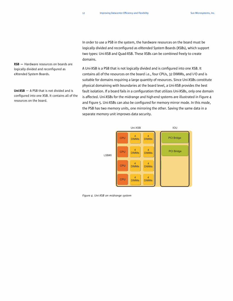
In order to use a PSB in the system, the hardware resources on the board must be
logically divided and reconfigured as eXtended System Boards (XSBs), which support
two types: Uni-XSB and Quad-XSB. These XSBs can be combined freely to create
domains.
A Uni-XSB is a PSB that is not logically divided and is configured into one XSB. It
contains all of the resources on the board i.e., four CPUs, 32 DIMMs, and I/O and is
suitable for domains requiring a large quantity of resources. Since Uni-XSBs constitute
physical domaining with boundaries at the board level, a Uni-XSB provides the best
fault isolation. If a board fails in a configuration that utilizes Uni-XSBs, only one domain
is affected. Uni-XSBs for the midrange and high-end systems are illustrated in Figure 4
and Figure 5. Uni-XSBs can also be configured for memory mirror mode. In this mode,
the PSB has two memory units, one mirroring the other. Saving the same data in a
separate memory unit improves data security.
Figure 4. Uni-XSB on midrange system
XSB — Hardware resources on boards are
logically divided and reconfigured as eXtended System Boards.
Uni-XSB — A PSB that is not divided and is
configured into one XSB. It contains all of the
resources on the board.
LSB#0
Uni-XSB IOU
CPU4
DIMMs PCI Bridge
PCI Bridge
4DIMMs
CPU
CPU
CPU
4DIMMs
4DIMMs
4DIMMs
4DIMMs
4DIMMs
4DIMMs
13 Improving Datacenter Efficiency and Flexibility Sun Microsystems, Inc.
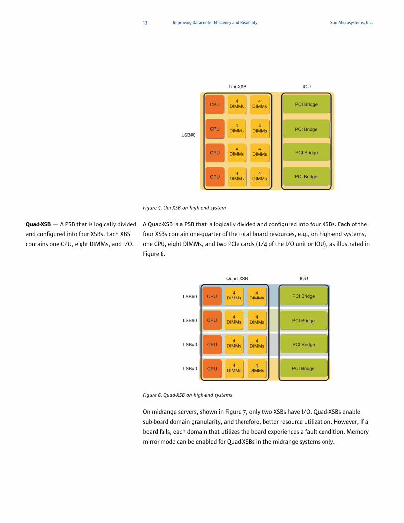
Figure 5. Uni-XSB on high-end system
A Quad-XSB is a PSB that is logically divided and configured into four XSBs. Each of the
four XSBs contain one-quarter of the total board resources, e.g., on high-end systems, one CPU, eight DIMMs, and two PCIe cards (1/4 of the I/O unit or IOU), as illustrated in
Figure 6.
Figure 6. Quad-XSB on high-end systems
On midrange servers, shown in Figure 7, only two XSBs have I/O. Quad-XSBs enable
sub-board domain granularity, and therefore, better resource utilization. However, if a
board fails, each domain that utilizes the board experiences a fault condition. Memory
mirror mode can be enabled for Quad-XSBs in the midrange systems only.
LSB#0
Uni-XSB IOU
CPU4
DIMMs PCI Bridge
PCI Bridge
4DIMMs
CPU
CPU
CPU
4DIMMs
4DIMMs
4DIMMs
4DIMMs
4DIMMs
4DIMMs PCI Bridge
PCI Bridge
Quad-XSB — A PSB that is logically divided
and configured into four XSBs. Each XBS
contains one CPU, eight DIMMs, and I/O.
LSB#0
Quad-XSB IOU
CPU4
DIMMs PCI Bridge
PCI Bridge
4DIMMs
CPU
CPU
CPU
4DIMMs
4DIMMs
4DIMMs
4DIMMs
4DIMMs
4DIMMs PCI Bridge
PCI Bridge
LSB#0
LSB#0
LSB#0

14 Improving Datacenter Efficiency and Flexibility Sun Microsystems, Inc.
Figure 7. Quad-XSB on midrange systems
A domain consists of one or more XSBs. Each domain runs its own copy of the Solaris OS
and must have a minimum of one CPU, eight DIMMs, and I/O. The number of domains
allowed depends on the server model. The default is one domain and the maximum
number of domains is 24. The maximum number of XSBs in a domain is 16. Domains
can be set up to include both Uni- and Quad-XSBs.
A domain component list (DCL) identifies the potential resources for a domain. A single
XSB can potentially belong to multiple domains. However, a single XSB can be assigned
to only one specific domain. The domain configuration software maps each XSB
number to a logical system board (LSB) number.
LSB#0
Quad-XSB IOU
CPU4
DIMMs PCI Bridge
PCI Bridge
4DIMMs
CPU
CPU
CPU
4DIMMs
4DIMMs
4DIMMs
4DIMMs
4DIMMs
4DIMMs
LSB#0
LSB#1
LSB#1
LSB — Logical system board mapping to
XSB number for domain configuration
purposes.
15 Improving Datacenter Efficiency and Flexibility Sun Microsystems, Inc.
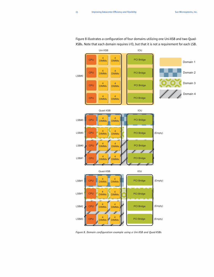
Figure 8 illustrates a configuration of four domains utilizing one Uni-XSB and two Quad-
XSBs. Note that each domain requires I/O, but that it is not a requirement for each LSB.
Figure 8. Domain configuration example using a Uni-XSB and Quad-XSBs
LSB#0
Quad-XSB IOU
CPU4
DIMMs PCI Bridge
PCI Bridge
4DIMMs
CPU
CPU
CPU
4DIMMs
4DIMMs
4DIMMs
4DIMMs
4DIMMs
4DIMMs PCI Bridge
PCI Bridge
LSB#0
LSB#0
LSB#1
LSB#0
Uni-XSB IOU
CPU4
DIMMs PCI Bridge
PCI Bridge
4DIMMs
CPU
CPU
CPU
4DIMMs
4DIMMs
4DIMMs
4DIMMs
4DIMMs
4DIMMs PCI Bridge
PCI Bridge
(Empty)
LSB#1
Quad-XSB IOU
CPU4
DIMMs PCI Bridge
PCI Bridge
4DIMMs
CPU
CPU
CPU
4DIMMs
4DIMMs
4DIMMs
4DIMMs
4DIMMs
4DIMMs PCI Bridge
PCI Bridge
LSB#1
LSB#2
LSB#3
(Empty)
(Empty)
(Empty)
Domain 1
Domain 2
Domain 3
Domain 4
16 Improving Datacenter Efficiency and Flexibility Sun Microsystems, Inc.
The Solaris OS is installed on a per-domain basis. The operating system image is
installed on internal disks. On midrange systems, the disks are available only for the
first (top) I/O device and the third (third from top) I/O device. The second and fourth I/O devices do not have the capability to support internal hard disks.
Fault isolation and error managementDomains are protected against software or hardware failures in other domains. Failures
in hardware shared between domains cause failures only in the domains that share the
hardware. When a domain encounters a fatal error, a domainstop operation occurs
that cleanly and quickly shuts down only the domain with the error. Domainstop
operates by shutting down the paths in and out of the system address controller and
the system data interface application-specific integrated circuits (ASICs). The shutdown
is intended to prevent further corruption of data, and to facilitate debugging by not
allowing the failure to be masked by continued operation.
When certain hardware errors occur in a Sun SPARC Enterprise M-Series server, the
system controller performs specific diagnosis and domain recovery steps. The following
automatic diagnosis engines identify and diagnose hardware errors that affect the
availability of the system and its domains:
• eXtended System Control Facility (XSCF) diagnosis engine — diagnoses hardware
errors associated with domain stops
• Solaris Operating System diagnosis engine — identifies non-fatal domain hardware
errors and reports them to the system controller
• POST diagnosis engine — identifies any hardware test failures that occur when the
power-on self-test is run
In most situations, hardware failures that cause a domain crash are detected and
eliminated from the domain configuration either by power-on self test (POST) or
OpenBoot PROM during the subsequent automatic recovery boot of the domain.
However, there can be situations where failures are intermittent or the boot-time tests
are inadequate to detect failures that cause repeated domain failures and reboots. In those situations, the XSCF uses configurations or configuration policies supplied by
the domain administrator to eliminate hardware from the domain configuration in an
attempt to get a stable domain environment running.
Dynamic ReconfigurationDynamic Reconfiguration (DR) and Automated Dynamic Reconfiguration (ADR) allow
resources to be dynamically reallocated, or balanced, between domains. Utilizing this
technology enables a physical or logical restructuring of the hardware components of
Sun SPARC Enterprise M-Series servers while the system is running and the applications
remain available. This high degree of resource flexibility allows the domain or platform
administrator to reconfigure the system easily in order to provision the resources to
17 Improving Datacenter Efficiency and Flexibility Sun Microsystems, Inc.
meet changing workload demands. Domain configurations can be optimized for
workloads that are either compute intensive, I/O intensive, or both. DR can also be
used to remove and replace failed or upgraded hardware components while the system
is online1.
DR functions of Sun SPARC Enterprise M-Series servers are performed on XSB units and
managed through the XSCF. The XSCF security management restricts DR operations to
administrators that have the proper access privileges. Three types of system board
components can be added or deleted by DR: CPU, memory, and I/O devices.
Dynamic Reconfiguration allows the domain or platform administrator to perform the
following functions:
• Display the DCL and domain status
• Display the status and state of system or I/O boards and some components to help
prepare for DR operations, including whether the board is Capacity-on-Demand (COD)
or not
• Test live boards
• Register system or I/O boards to the DCLs of domains
• Delete (electrically isolate) system or I/O boards from a domain in preparation for
moving to another domain or removal from the system while the domain remains
running
• Add system or I/O boards to a domain to add resources or replace a removed board,
while the domain remains running
• Configure or unconfigure CPU or memory modules on system boards to control
power and capacity of a domain or isolate faulty components
• Enable or disable peripheral component interconnect (PCI) cards or related
components and slots
• Reserve a system board to a domain
For example, on Sun SPARC Enterprise M8000 and M9000 servers the IT operator can
use DR to delete a faulty system board, then use the system’s hot-plug feature to
physically remove it. After plugging in the repaired board or a replacement, DR can be
used to add the board into the domain. System or I/O boards can also be associated
with multiple domains for load balancing or to provide extra capabilities for specific
tasks. However, resources can only be assigned to one domain at a time. In addition,
combining the capabilities of DR with network and storage multipathing solutions can
foster creation of redundant network or storage subsystems with automatic failover,
load balancing, and dynamic reconfiguring capabilities.
1.Sun SPARC Enterprise M4000, M5000, M8000, and M9000 servers can perform DR to logically move system resources between domains. In addition, Sun SPARC Enterprise M8000 and M9000 servers can perform hot-swap operations to physically add or remove boards from the chassis.
18 Improving Datacenter Efficiency and Flexibility Sun Microsystems, Inc.
Basic DR functionsAll system boards that are targets of DR operations must be registered in the target
domain’s DCL through XSCF. The basic functions of DR are: add, delete, move, and
replace.
• Add — DR can be used to add a system board to a domain without stopping the
Solaris OS provided that the board is installed in the system and not assigned to
another domain. A system board is added in three stages: assign, connect, and
configure. In the add operation, the selected system board is assigned to the target
domain so that it is connected to the domain. Then, the system board is configured
to the Solaris OS of the domain. At this point, the system board is added to the
domain, and its CPU and memory resources can be used by that domain.
• Delete — DR can be used to delete a system board from a domain without stopping
the Solaris OS running in that domain. A system board is deleted in three stages:
unconfigure, disconnect, and unassign. In the delete operation, the selected system
board is unconfigured from its domain by the Solaris OS. Then, the board is
disconnected to unassign it from the domain. At this point, the system board is
deleted from the domain.
• Move — DR can be used to reassign a system board from one domain to another
without stopping the Solaris OS running in either domain. The move function
changes the configurations of both domains without physically removing and
remounting the system board. The move operation for a system board is a serial
combination of the delete and add operations. In other words, the selected system
board is deleted from its domain and then added to the target domain.
• Replace —DR can be used to remove a system board from a domain and either add it
back later or replace it with another system board, without stopping the Solaris OS
running on that domain provided both boards satisfy DR requirements (such as not
making up an entire domain, no processes are running on the CPU, etc.). In the
replace operation, the selected system board is deleted from the OS of the domain.
Then, the system board is removed when it is ready to be released from its domain.
After field parts replacement or other such task, the system board is reinstalled and
added. DR cannot be used to replace a system board in a midrange system because
replacing a system board replaces a motherboard unit (MBU). To replace a system
board in a midrange system, turn off the power of all domains, and then perform
hardware replacement.
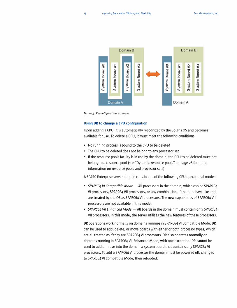
In the example shown in Figure 9, system board #2 is deleted from domain A and added
to domain B. In this way, the physical configuration of the hardware (mounting
locations) is not changed but the logical configuration is changed for management of
the system boards.
19 Improving Datacenter Efficiency and Flexibility Sun Microsystems, Inc.
Figure 9. Reconfiguration example
Using DR to change a CPU configuration
Upon adding a CPU, it is automatically recognized by the Solaris OS and becomes
available for use. To delete a CPU, it must meet the following conditions:
• No running process is bound to the CPU to be deleted
• The CPU to be deleted does not belong to any processor set
• If the resource pools facility is in use by the domain, the CPU to be deleted must not
belong to a resource pool (see “Dynamic resource pools” on page 28 for more
information on resource pools and processor sets)
A SPARC Enterprise server domain runs in one of the following CPU operational modes:
• SPARC64 VI Compatible Mode — All processors in the domain, which can be SPARC64
VI processors, SPARC64 VII processors, or any combination of them, behave like and
are treated by the OS as SPARC64 VI processors. The new capabilities of SPARC64 VII
processors are not available in this mode.
• SPARC64 VII Enhanced Mode — All boards in the domain must contain only SPARC64
VII processors. In this mode, the server utilizes the new features of these processors.
DR operations work normally on domains running in SPARC64 VI Compatible Mode. DR
can be used to add, delete, or move boards with either or both processor types, which
are all treated as if they are SPARC64 VI processors. DR also operates normally on
domains running in SPARC64 VII Enhanced Mode, with one exception: DR cannot be
used to add or move into the domain a system board that contains any SPARC64 VI
processors. To add a SPARC64 VI processor the domain must be powered off, changed
to SPARC64 VI Compatible Mode, then rebooted.
Syste
mB
oard
#0
Syste
mB
oard
#1
Syste
mB
oard
#2
Syste
mB
oard
#3
Syste
mB
oard
#0
Syste
mB
oard
#1
Syste
mB
oard
#2
Syste
mB
oard
#3
Domain A Domain A
Domain BDomain B
20 Improving Datacenter Efficiency and Flexibility Sun Microsystems, Inc.
Using DR to change memory configurations
The DR functions classify system boards by memory usage into two types: kernel
memory board and user memory board. A kernel memory board is a system board on
which kernel memory (i.e., memory internally used by the Solaris OS and containing an
OpenBoot PROM program) is loaded. Kernel memory is allocated in the memory on a
single system board as much as possible. If all memory on the system board is not
allocated to kernel memory and more kernel memory must be added, the memory on
another system board is also used.
DR operations can be performed on kernel memory boards. When a kernel memory
board is deleted, the system is suspended and kernel memory on the system board to
be deleted is copied into memory on another system board. The copy destination board
cannot have any kernel memory, must have the same or more memory, and must have
the same memory configuration as the system board to be deleted.
Kernel cage memory is a function used to minimize the number of system boards to
which kernel memory is allocated. Kernel cage memory is enabled by default in the
Solaris 10 OS. If the kernel cage is disabled, the system might run more efficiently, but
kernel memory is spread among all boards and DR operations do not work on memory
if the kernel cage is disabled.
A user memory board is a system board on which no kernel memory is loaded. Before
deleting user memory, the system attempts to swap out the physical pages to the swap
area of disks. Sufficient swap space must be available for this operation to succeed.
Some user pages are locked into memory and cannot be swapped out. These pages
receive special treatment by DR. Intimate Shared Memory (ISM) pages are special user
pages that are shared by all processes. ISM pages are permanently locked and cannot
be swapped out as memory pages. ISM is usually used by database software to achieve
better performance. Locked pages cannot be swapped out, but the system
automatically moves these pages to the memory on another system board. Deleting
user memory fails if there is not sufficient free memory size on the remaining system
boards to hold the relocated pages.
Using DR to change I/O configurations
In the domain where DR is performed, all device drivers must support the addition of
devices by DR. When DR adds an I/O device, it is reconfigured automatically. An I/O
device can be deleted when the device is not in use in the domain where the DR
operation is to be performed and the device drivers in the domain support DR. In addition, all PCI cards and I/O device interfaces on a system board must support DR.
If not, DR operations cannot be executed on that system board. In this case, the power
supply to the domain must be turned off before performing maintenance and
installation.
21 Improving Datacenter Efficiency and Flexibility Sun Microsystems, Inc.
In most cases, the device to be deleted is in use. For example, the root file system or
any other file systems required for operation cannot be unmounted. To solve this
problem, the system can be configured using redundant configuration software to
make the access path to each I/O device redundant. One way to accomplish this for
disk drives is to employ disk mirroring software.
PCI slots support hot-plug. Before a PCI card can be removed it must be unconfigured
and disconnected. XSCF controls DR events, but since hot-plug is controlled entirely
within the Solaris OS, XSCF is not aware of hot-plug events, including I/O Box hot-plug
events. The Solaris Service Manager includes a new daemon, oplhpd, that listens for
I/O DR events and sends messages to XSCF. XSCF uses this information to keep track of
faulty I/O cards and when they are replaced.
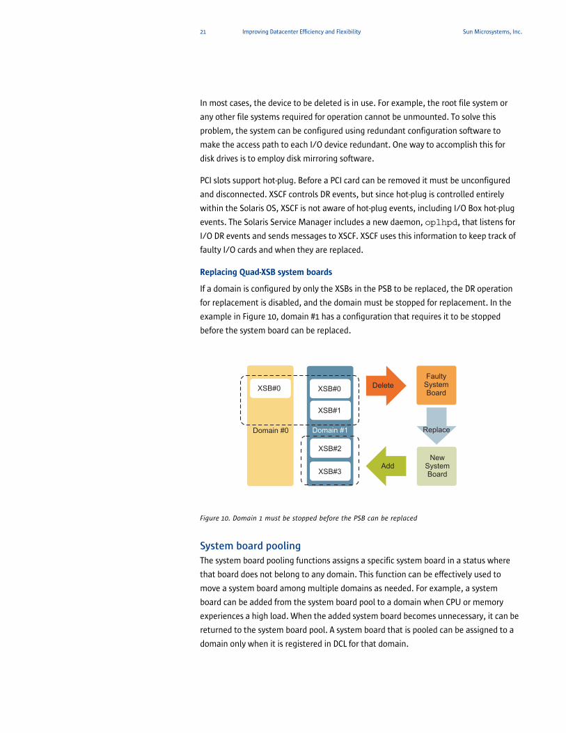
Replacing Quad-XSB system boards
If a domain is configured by only the XSBs in the PSB to be replaced, the DR operation
for replacement is disabled, and the domain must be stopped for replacement. In the
example in Figure 10, domain #1 has a configuration that requires it to be stopped
before the system board can be replaced.
Figure 10. Domain 1 must be stopped before the PSB can be replaced
System board poolingThe system board pooling functions assigns a specific system board in a status where
that board does not belong to any domain. This function can be effectively used to
move a system board among multiple domains as needed. For example, a system
board can be added from the system board pool to a domain when CPU or memory
experiences a high load. When the added system board becomes unnecessary, it can be
returned to the system board pool. A system board that is pooled can be assigned to a
domain only when it is registered in DCL for that domain.
FaultySystemBoard
Replace
Delete
AddNew
SystemBoard
Domain #1Domain #0
XSB#0 XSB#0
XSB#1
XSB#2
XSB#3
22 Improving Datacenter Efficiency and Flexibility Sun Microsystems, Inc.
Reserving domain configuration changesA domain configuration change is reserved when a system board cannot be added,
deleted, or moved immediately for operational reasons. The reserved add, delete, or
move of the system board is executed when the power of the target domain is on or off,
or the domain is rebooted. If a system board used as a floating board is pooled in the
system board pool, a domain configuration change can be reserved to assign the
system board to the intended domain in advance, preventing the system board from
being acquired by another domain.
Automatic Dynamic ReconfigurationAutomatic DR enables an application to execute DR operations without requiring user
interaction. This ability is provided by an enhanced DR framework that includes the
Reconfiguration Coordination Manager and the system event facility. The
Reconfiguration Coordination Manager executes preparatory tasks before a DR
operation, error recovery during a DR operation, and cleanup after a DR operation. The automatic DR framework enables applications to automatically give up resources
prior to unconfiguring them, and to capture new resources as they are configured into
the domain.
Global Automatic Dynamic ReconfigurationRemote DR and local automatic DR functions are building blocks for a feature called
global automatic DR. Global automatic DR introduces a framework that can be used to
automatically redistribute the system board resources on a Sun SPARC Enterprise M-
Series system. This redistribution can be based upon factors such as production
schedule, domain resource utilizations, domain functional priorities, and so on. Global
automatic DR accepts input describing resource utilization policies and then uses those
policies to automatically marshal the Sun SPARC Enterprise M-Series system resources
to produce the most effective utilization.
Capacity on DemandCapacity on Demand (COD) is an innovative procurement model enabled by Dynamic
Domains. With COD, fully-configured systems are shipped with only a portion of their
resources enabled — in accordance with current needs. Additional processors and
memory are installed but initially disabled with a licensing mechanism. Under certain
conditions, COD boards can be used before actually purchasing a license.
When a system encounters a resource constraint, additional capacity can be quickly
enabled by purchasing a right-to-use (RTU) license. Processors and memory can then be
added to existing or new domains on the system. This approach helps avoid the

23 Improving Datacenter Efficiency and Flexibility Sun Microsystems, Inc.
potentially costly possibility of overburdening critical systems when workload
increases, helps reduce system outages, and reduces upgrades that take valuable time
to execute.
24 Simplifying Application Consolidation Sun Microsystems, Inc.
Chapter 3
Simplifying Application Consolidation
Utilizing the power of Dynamic Domains, development, prototype, and production
environments can be combined on a single large server, rather than on three separate
servers. Still other consolidation projects combine multiple database instances and
application servers within a single system, sharing the same operating system instance
and providing cost savings in administrative tasks such as data management and
archive. While Dynamic Domains supports consolidation of several systems into one
Sun SPARC Enterprise M-Series server, Solaris Containers technology refines resource
control further to simplify the consolidation of several applications into one domain.
The Solaris Containers functionality in the Solaris 10 OS enables multiple, software-
isolated applications to run on a single server or domain. With this capability
organizations can easily deploy multiple applications on a single server while
maintaining software boundaries.
In some cases, operating system version incompatibilities between existing
applications and new hardware can stall the overall consolidation initiative. Solaris 8
Containers and Solaris 9 Containers software can help mitigate this issue. These tools
capture and transfer the configuration, data, and other operating system elements that
surround an existing application. Utilizing this technology, older applications can
deploy within a Solaris Container on the Solaris 10 OS — despite dependencies on the
Solaris 8 OS or Solaris 9 OS. By encapsulating the application within a Solaris Container,
the Solaris 8 or Solaris 9 runtime environment is made available to the application as
needed.
By taking advantage of Solaris 8 and Solaris 9 Containers software, a consolidation
project utilizing the Solaris 10 OS can efficiently address the needs of applications
which currently reside on the Solaris 8, Solaris 9, and Solaris 10 OS. Furthermore, these
older applications can now reap the benefits of the greater compute power, reduction
of space, and lower power and cooling requirements offered by Sun SPARC Enterprise
M-Series servers.
Solaris™ Containers technologyWith Solaris Containers technology, IT operators can gain tight control over allocation
of system and network resources. Configurations can even favor certain users in mixed
workload environments. For example, in large brokerage firms, traders intermittently
require fast access to execute a query or perform a calculation, while other system
users have more consistent workloads. Using Solaris Containers, traders can be granted
a proportionately larger number of shares of resources to give them the system
resources they require.
25 Simplifying Application Consolidation Sun Microsystems, Inc.
A Solaris Container is a complete runtime environment for applications. Solaris 10
Resource Manager software and Solaris Zones software partitioning technology are
both parts of the container. These components address different qualities the container
can deliver and work together to create a complete container. The zones portion of the
container provides a virtual mapping from the application to the platform resources.
Zones allow application components to be isolated from one another even though the
zones share a single instance of the Solaris OS. The Solaris Resource Manager software
provides the capability to allocate the quantity of resources that a workload in a zone
receives.
Containers establish boundaries for resources, such as CPUs, and can be expanded to
adapt to the changing processing requirements of the application or applications
running in the container. A container is a virtualized operating system environment
created within a single instance of the Solaris OS. Applications within containers are
isolated, preventing processes in one container from monitoring or affecting processes
running in another container. Even a superuser process from one container can not
view or affect activity in other containers. A container also provides an abstract layer
that separates applications from the physical attributes of the system on which they
are deployed. Examples of these attributes include physical device paths.
Containers enable more efficient utilization of the system. Dynamic resource
reallocation permits unused resources to be shifted to other containers as needed.
Fault and security isolation means that poorly behaved applications do not require a
dedicated and under-utilized system. With containers, these applications can be
consolidated with other applications. Containers also allow the IT operator to delegate
some administrative functions while maintaining overall system security.
Solaris Containers are designed to provide fine-grained control over the resources that
applications use, allowing multiple applications to operate on a single server while
maintaining specified Quality-of-Service (QoS) levels. Fixed resources such as processors
and memory can be partitioned into pools on multiprocessor systems, with different
pools shared by different projects (a specified collection of processes) and isolated
application environments. Dynamic resource sharing allows different projects to be
assigned different ratios of system resources.
When resources such as CPUs and memory are dynamically allocated, resource capping
controls can be used to set limits on the amount of resources used by a project. With all
of these resource management capabilities, organizations can consolidate many
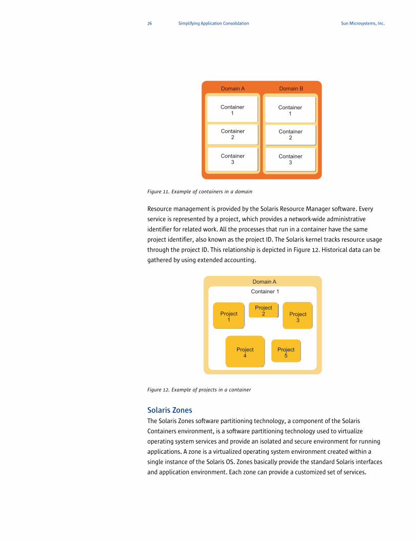
applications onto one server, as illustrated in Figure 11, helping to reduce operational
and administrative costs while increasing availability.
26 Simplifying Application Consolidation Sun Microsystems, Inc.
Figure 11. Example of containers in a domain
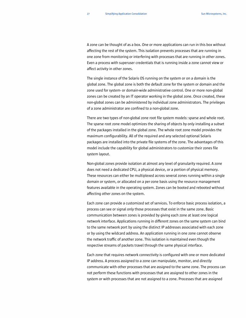
Resource management is provided by the Solaris Resource Manager software. Every
service is represented by a project, which provides a network-wide administrative
identifier for related work. All the processes that run in a container have the same
project identifier, also known as the project ID. The Solaris kernel tracks resource usage
through the project ID. This relationship is depicted in Figure 12. Historical data can be
gathered by using extended accounting.
Figure 12. Example of projects in a container
Solaris ZonesThe Solaris Zones software partitioning technology, a component of the Solaris
Containers environment, is a software partitioning technology used to virtualize
operating system services and provide an isolated and secure environment for running
applications. A zone is a virtualized operating system environment created within a
single instance of the Solaris OS. Zones basically provide the standard Solaris interfaces
and application environment. Each zone can provide a customized set of services.
Domain A
Container1
Container3
Container2
Container1
Container3
Container2
Domain B
Domain A
Container 1
Project1
Project5
Project3
Project4
Project2
27 Simplifying Application Consolidation Sun Microsystems, Inc.
A zone can be thought of as a box. One or more applications can run in this box without
affecting the rest of the system. This isolation prevents processes that are running in
one zone from monitoring or interfering with processes that are running in other zones.
Even a process with superuser credentials that is running inside a zone cannot view or
affect activity in other zones.
The single instance of the Solaris OS running on the system or on a domain is the
global zone. The global zone is both the default zone for the system or domain and the
zone used for system- or domain-wide administrative control. One or more non-global
zones can be created by an IT operator working in the global zone. Once created, these
non-global zones can be administered by individual zone administrators. The privileges
of a zone administrator are confined to a non-global zone.
There are two types of non-global zone root file system models: sparse and whole root.
The sparse root zone model optimizes the sharing of objects by only installing a subset
of the packages installed in the global zone. The whole root zone model provides the
maximum configurability. All of the required and any selected optional Solaris
packages are installed into the private file systems of the zone. The advantages of this
model include the capability for global administrators to customize their zones file
system layout.
Non-global zones provide isolation at almost any level of granularity required. A zone
does not need a dedicated CPU, a physical device, or a portion of physical memory.
These resources can either be multiplexed across several zones running within a single
domain or system, or allocated on a per-zone basis using the resource management
features available in the operating system. Zones can be booted and rebooted without
affecting other zones on the system.
Each zone can provide a customized set of services. To enforce basic process isolation, a
process can see or signal only those processes that exist in the same zone. Basic
communication between zones is provided by giving each zone at least one logical
network interface. Applications running in different zones on the same system can bind
to the same network port by using the distinct IP addresses associated with each zone
or by using the wildcard address. An application running in one zone cannot observe
the network traffic of another zone. This isolation is maintained even though the
respective streams of packets travel through the same physical interface.
Each zone that requires network connectivity is configured with one or more dedicated
IP address. A process assigned to a zone can manipulate, monitor, and directly
communicate with other processes that are assigned to the same zone. The process can
not perform these functions with processes that are assigned to other zones in the
system or with processes that are not assigned to a zone. Processes that are assigned
28 Simplifying Application Consolidation Sun Microsystems, Inc.
to different zones are only able to communicate through network APIs (application
programming interfaces). In addition, exclusive IP non-global zones can be configured.
These zones have their own IP-related state.
For more information on consolidating applications using Solaris Containers see: http:/www.sun.com/software/solaris/reference_resources.jsp.
Solaris Resource Manager softwareModern computing environments have to provide a flexible response to the varying
workloads that are generated by different, consolidated applications on a system. A workload is an aggregation of all processes of an application or group of applications.
The Solaris OS provides a facility called projects to name workloads once they are
identified. For example, one project for a sales database and another project for a
marketing database. If resource management features are not used, the Solaris OS
responds to workload demands by adapting to new application requests dynamically.
This default response generally means that all activity on the system is given equal
access to resources.
Solaris Resource Manager software enables systems to treat workloads individually by:
• Restricting access to a specific resource
• Offering resources to workloads on a preferential basis
• Isolating workloads from each another
• Denying resources or prefer one application over another for a larger set of
allocations than otherwise permitted
• Preventing an application from consuming resources indiscriminately
• Changing an application’s priority based on external events
• Balancing resource guarantees to a set of applications against the goal of
maximizing system utilization
These capabilities enable Solaris Containers to deliver predictable service levels.
Effective resource management is enabled in the Solaris OS by offering control,
notification, and monitoring mechanisms. Many of these capabilities are provided
through enhancements to existing mechanisms such as the proc(4) file system,
processor sets, scheduling classes, and new mechanisms such as dynamic resource
pools.
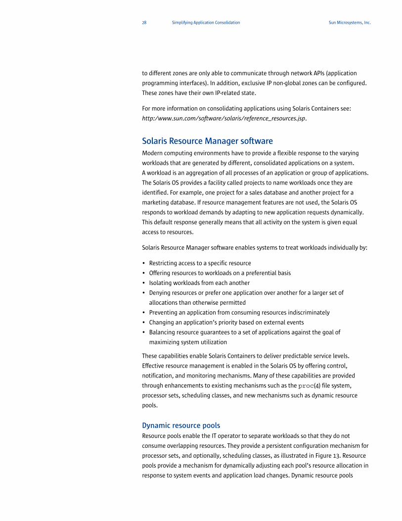
Dynamic resource poolsResource pools enable the IT operator to separate workloads so that they do not
consume overlapping resources. They provide a persistent configuration mechanism for
processor sets, and optionally, scheduling classes, as illustrated in Figure 13. Resource
pools provide a mechanism for dynamically adjusting each pool’s resource allocation in
response to system events and application load changes. Dynamic resource pools
29 Simplifying Application Consolidation Sun Microsystems, Inc.
simplify and reduce the number of decisions required from the IT operator. Pools are
automatically adjusted to preserve the system performance goals. The software
periodically examines the load on the system and determines whether intervention is
require to enable the system to maintain optimal performance.
Figure 13. Resource pools
On a system that has zones enabled, a non-global zone can be associated with one
resource pool, although the pool need not be exclusively assigned to a particular zone.
Moreover, individual processes in non-global zones cannot be bound to a different pool
by using the poolbind command from the global zone. If a scheduling class is set for
a pool and a non-global zone is associated with that pool, the zone uses that
scheduling class by default.
Resource management controlThe Solaris OS provides three types of control mechanisms to control resource usage:
• Constraint — a resource sharing mechanism that sets bounds on the amount of
specific resources a workload can consume. It can also be used to control ill-behaved
applications, such as applications with memory leaks, that can otherwise
compromise performance or availability through unregulated resource requests.
• Scheduling — a resource sharing mechanism that refers to making a sequence of
resource allocation decisions at specific intervals based on a predictable algorithm.
An application that does not need its current allocation leaves the resource available
for another application’s use. Scheduling-based resource management enables full
utilization of an under-committed configuration, while providing controlled
allocations in a critically committed or overcommitted scenario. The algorithm
determines the level of control. For example, it might guarantee that all applications
have some access to the resource. The fair share scheduler is an example of a
scheduling mechanism that manages application access to CPU resources in a
controlled manner.
• Partitioning — a more rigid mechanism used to bind a workload to a subset of the
system’s available resources. This binding guarantees that a known amount of
resources are always available to the workload. Resource pools are a partitioning
Scheduling Class(optional)
Processor Set
Resource Pool
30 Simplifying Application Consolidation Sun Microsystems, Inc.
mechanism that limit workloads to a specific subset of the resources of the system.
Partitioning can be used to avoid system-wide over commitment. However, in
avoiding this over commitment, the ability to achieve high utilizations can be
reduced because resources bound to one pool are not available for use by a workload
in another pool when the workload bound to them is idle, unless a policy for dynamic
resource pools is employed. A good candidate for this type of control mechanism
might be transaction processing systems that must be guaranteed a certain amount
of resources at all times.
Managing CPU resources with resource poolsThe ability to partition a server using processor sets has been available since version 2.6
of the Solaris OS. Every system contains at least one processor set — the system or
default processor set that consists of all of the processors in the system. Additional
processor sets can be dynamically created and removed on a running system, providing
that at least one CPU remains for the system processor set.
Resource pools enable IT operators to create a processor set by specifying the number
of processors required, rather than CPU physical IDs. The definition of a processor set is
therefore not tied to any particular type of hardware. It is also possible to specify a
minimum and maximum number of processors for a pool. Multiple configurations can
be defined to adapt to changing resource requirements, such as different daily, nightly,
or seasonal workloads. Resource pools can have different scheduling classes.
Scheduling classes work per resource pool. The two most common are the Fair Share
Scheduler and the Time Sharing Scheduler.
Fair share scheduler (FSS)The fair share scheduler allocates CPU resources using CPU shares. The FSS helps
ensure that CPU resources are distributed among active zones or projects based on the
number of shares each zone or project is allocated. Therefore, more important
workloads should be allocated more CPU shares. A CPU share defines the portion of the
CPU resources available to a project in a resource pool. It is important to note that CPU
shares are not the same as CPU percentages. Shares define the relative importance of
projects with respect to other projects. If the project A is twice as important as the
project B, then project A should be assigned twice as many shares as project B. The actual number of shares assigned is largely irrelevant — 2 shares for project A
versus 1 share for project B yields the same results as 18 shares for project A versus 9 shares for project B. Project A is entitled to twice the amount of CPU as project B in
both cases. The importance of project A relative to project B can be increased by
assigning more shares to project A while keeping the same number of shares for project B.
31 Simplifying Application Consolidation Sun Microsystems, Inc.
The fair share scheduler calculates the proportion of CPU allocated to a project by
dividing the shares for the project by the total number of active projects. An active
project is a project with at least one process using the CPU. Shares for idle projects, i.e.,
projects with no active processes, are not used in the calculations. An important thing
to note is that the fair share scheduler only limits CPU usage if there is competition for
the CPU. A project that is the only active project on the system can use 100 percent of
the CPU, regardless of the number of shares it holds. CPU cycles are never wasted — if a project does not use all of the CPU it is entitled to because it has no work to
perform, the remaining CPU resources are distributed between other active processes.
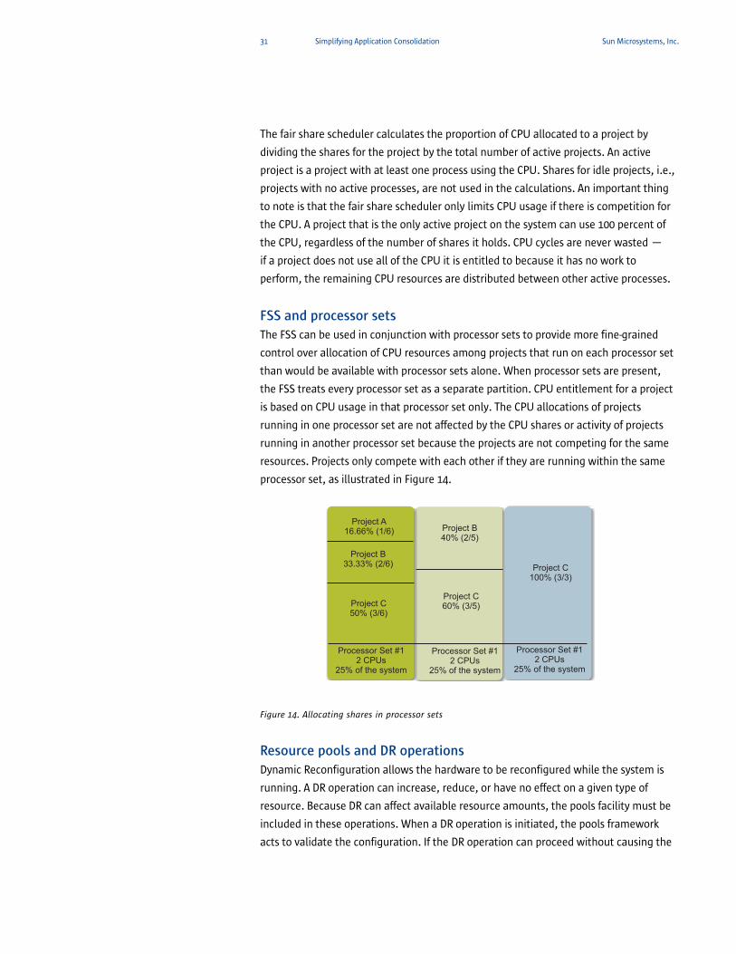
FSS and processor setsThe FSS can be used in conjunction with processor sets to provide more fine-grained
control over allocation of CPU resources among projects that run on each processor set
than would be available with processor sets alone. When processor sets are present,
the FSS treats every processor set as a separate partition. CPU entitlement for a project
is based on CPU usage in that processor set only. The CPU allocations of projects
running in one processor set are not affected by the CPU shares or activity of projects
running in another processor set because the projects are not competing for the same
resources. Projects only compete with each other if they are running within the same
processor set, as illustrated in Figure 14.
Figure 14. Allocating shares in processor sets
Resource pools and DR operationsDynamic Reconfiguration allows the hardware to be reconfigured while the system is
running. A DR operation can increase, reduce, or have no effect on a given type of
resource. Because DR can affect available resource amounts, the pools facility must be
included in these operations. When a DR operation is initiated, the pools framework
acts to validate the configuration. If the DR operation can proceed without causing the
Processor Set #12 CPUs
25% of the system
Processor Set #12 CPUs
25% of the system
Processor Set #12 CPUs
25% of the system
Project A16.66% (1/6)
Project B33.33% (2/6)
Project C50% (3/6)
Project B40% (2/5)
Project C60% (3/5)
Project C100% (3/3)
32 Simplifying Application Consolidation Sun Microsystems, Inc.
current pools configuration to become invalid, then the private configuration file is
updated. An invalid configuration is one that can not be supported by the available
resources.
If the DR operation causes the pools configuration to be invalid, then the operation fails
and the IT operator is notified by a message to the message log. The configuration can
be forced to complete using the DR force option. The pools configuration is then
modified to comply with the new resource configuration. For information on the DR
process and the force option, see the Dynamic Reconfiguration User Guide for the Sun
hardware on which the pools are running.
33 Managing the Virtualized Environment Sun Microsystems, Inc.
Chapter 4
Managing the Virtualized Environment
Even in a consolidated environment with a reduced number of platforms,
administrators need solutions that simplify management of IT infrastructure. Sun
SPARC Enterprise M-Series servers offer built-in management capabilities to ease
common administrative tasks. In addition, utilizing Sun™ Management Center software
adds key capabilities including advanced monitoring, system diagnostics, and specific
functions to address the needs of virtualized environments.
eXtended system controller facility (XSCF)Around the clock system operation, disaster recovery hot sites, and geographically
dispersed organizations lead to requirements for efficient, remote management of
systems. One of the many benefits of Sun SPARC Enterprise M-Series servers is the
support for system management capabilities through an on-board service processor.
XSCF firmware is pre-installed on the service processor boards and consists of system
management applications and two user interfaces: XSCF Web (a browser-based GUI)
and XSCF Shell (a terminal-based CLI). The XSCF Web uses the secure version of the
HyperText Transfer Protocol (https) and the Secure Sockets Layer/Transport Level
Security (SSL/TLS) protocols for connection to the server connected to a network and
for Web-based support of server status display, server operation control, and
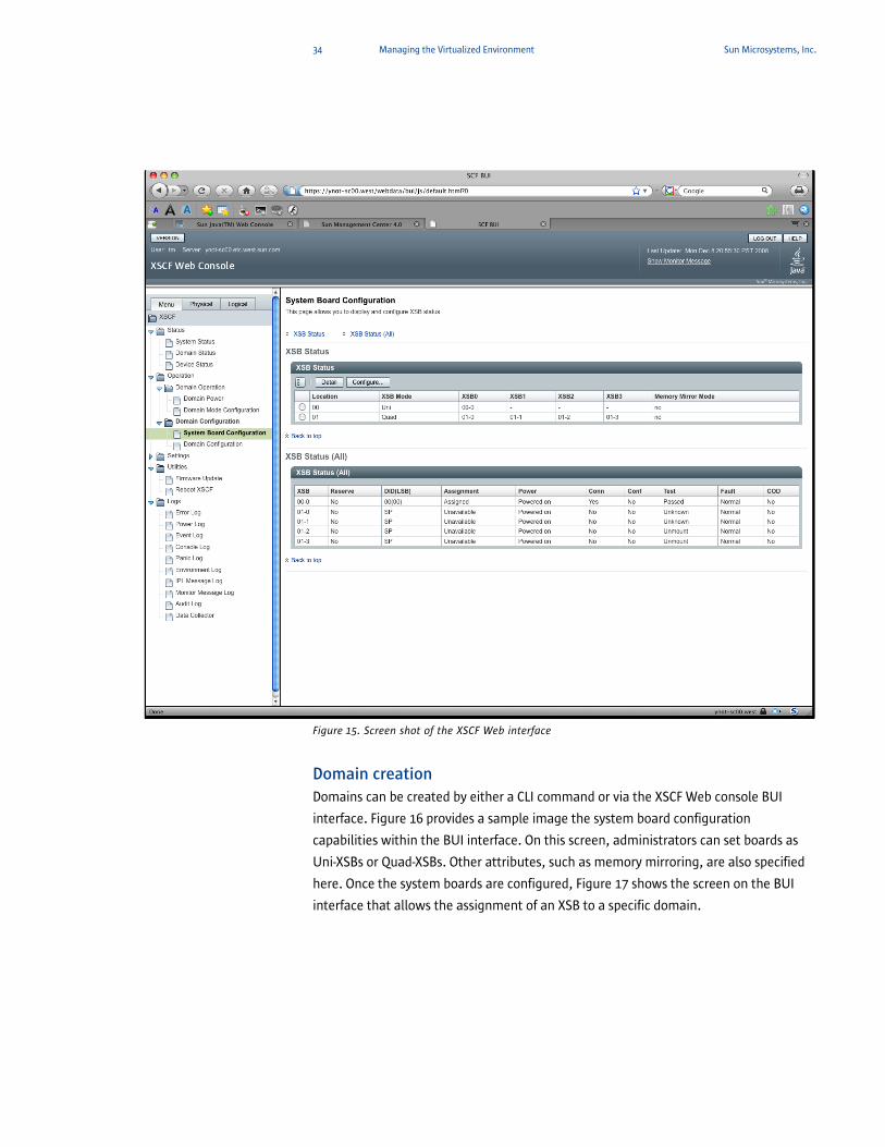
configuration information display. Figure 15 provides an example of the XSCF Web (BUI)
interface.
The XSCF firmware is a single centralized point for managing hardware configuration,
controlling the hardware monitor and cooling system (fan units), monitoring domain
status, powering on/off peripheral units, and monitoring errors. The XSCF centrally
controls and monitors the server. The XSCF includes a partitioning function to configure
and control domains. It has a function to monitor the server through an Ethernet
connection to enable remote control. It also reports failure information to the system
administrator.
To gain additional management capabilities, Sun SPARC Enterprise M-Series servers can
be managed by Sun Management Center software or third party management tools.
The XSCF supports communication with third party management tools using either
built-in Simple Network Management Protocol (SNMP) or Sun Management Center
software agents.
34 Managing the Virtualized Environment Sun Microsystems, Inc.
Figure 15. Screen shot of the XSCF Web interface
Domain creationDomains can be created by either a CLI command or via the XSCF Web console BUI
interface. Figure 16 provides a sample image the system board configuration
capabilities within the BUI interface. On this screen, administrators can set boards as
Uni-XSBs or Quad-XSBs. Other attributes, such as memory mirroring, are also specified
here. Once the system boards are configured, Figure 17 shows the screen on the BUI
interface that allows the assignment of an XSB to a specific domain.
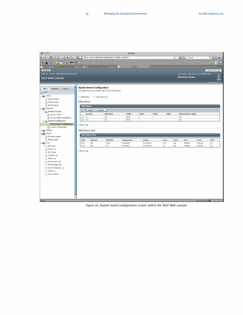
35 Managing the Virtualized Environment Sun Microsystems, Inc.
Figure 16. System board configuration screen within the XSCF Web console
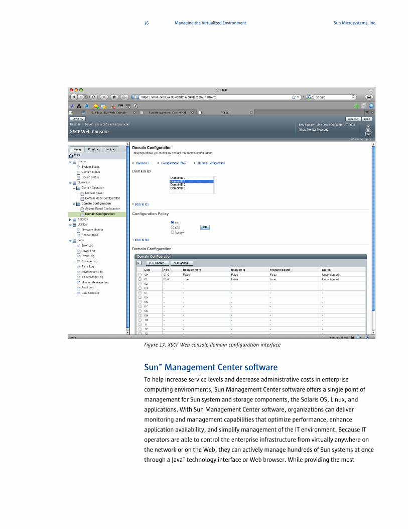
36 Managing the Virtualized Environment Sun Microsystems, Inc.
Figure 17. XSCF Web console domain configuration interface
Sun™ Management Center softwareTo help increase service levels and decrease administrative costs in enterprise
computing environments, Sun Management Center software offers a single point of
management for Sun system and storage components, the Solaris OS, Linux, and
applications. With Sun Management Center software, organizations can deliver
monitoring and management capabilities that optimize performance, enhance
application availability, and simplify management of the IT environment. Because IT
operators are able to control the enterprise infrastructure from virtually anywhere on
the network or on the Web, they can actively manage hundreds of Sun systems at once
through a Java™ technology interface or Web browser. While providing the most
37 Managing the Virtualized Environment Sun Microsystems, Inc.
comprehensive instrumentation and administrative knowledge for Sun environments,
open interfaces enable information to be shared with other management platforms,
thus lowering the total cost of system management.
Sun Management Center software supports full integration with Dynamic Domains,
Dynamic Reconfiguration, Reconfiguration Coordination Manager, Solaris Containers,
and IP Network Multipathing. Tight integration of Sun Management Center software
with major enterprise management frameworks such as CA Unicenter and IBM Tivoli,
help simplify management of heterogeneous IT environments.
Sun Management Center software for Sun SPARC Enterprise M-Series systems is an
extensible monitoring and management tool that integrates standard SNMP-based
management structures with intelligent and autonomous agent and management
technology. Sun Management Center software is used as the GUI and SNMP manager
and agent infrastructure for the Sun SPARC Enterprise M-Series system. The SNMP
agent is part of the XSCP software, and can be loaded into any domain. The agent
exports all information relevant for monitoring at the system, component, and domain
levels to Sun Management Center software.
Sun Management Center software is accessed through a Java technology-based GUI
that is intended to provide a common look and feel for all Sun Management Center
software applications, and offers the flexibility to monitor and manage the enterprise
from any platform supporting Java technology. It allows proactive and automated
management of complex and common administrative tasks, reducing the likelihood of
costly errors and promoting high availability. Another important feature is the ability to
perform predictive failure analysis, alerting operators to potential memory and disk
failures on a statistical basis, aiding decision making, and increasing availability.
Sun Management Center software includes the following features.
• System management — monitors and manages the system at the hardware and
operating system levels. Monitored hardware includes boards, tapes, power
supplies, and disks.
• Operating system management — monitors and manages operating system
parameters that include load, resource usage, disk space, and network statistics.
• Application and business system management — provides enabling technology to
monitor business applications such as trading systems, accounting systems,
inventory systems, and control systems.
• Scalability — provides an open, scalable, and flexible solution to configure and
manage multiple management administrative domains. These domains consist of
many systems and span across an enterprise. IT operators can configure the software
in a centralized or distributed fashion so that the product supports multiple users.
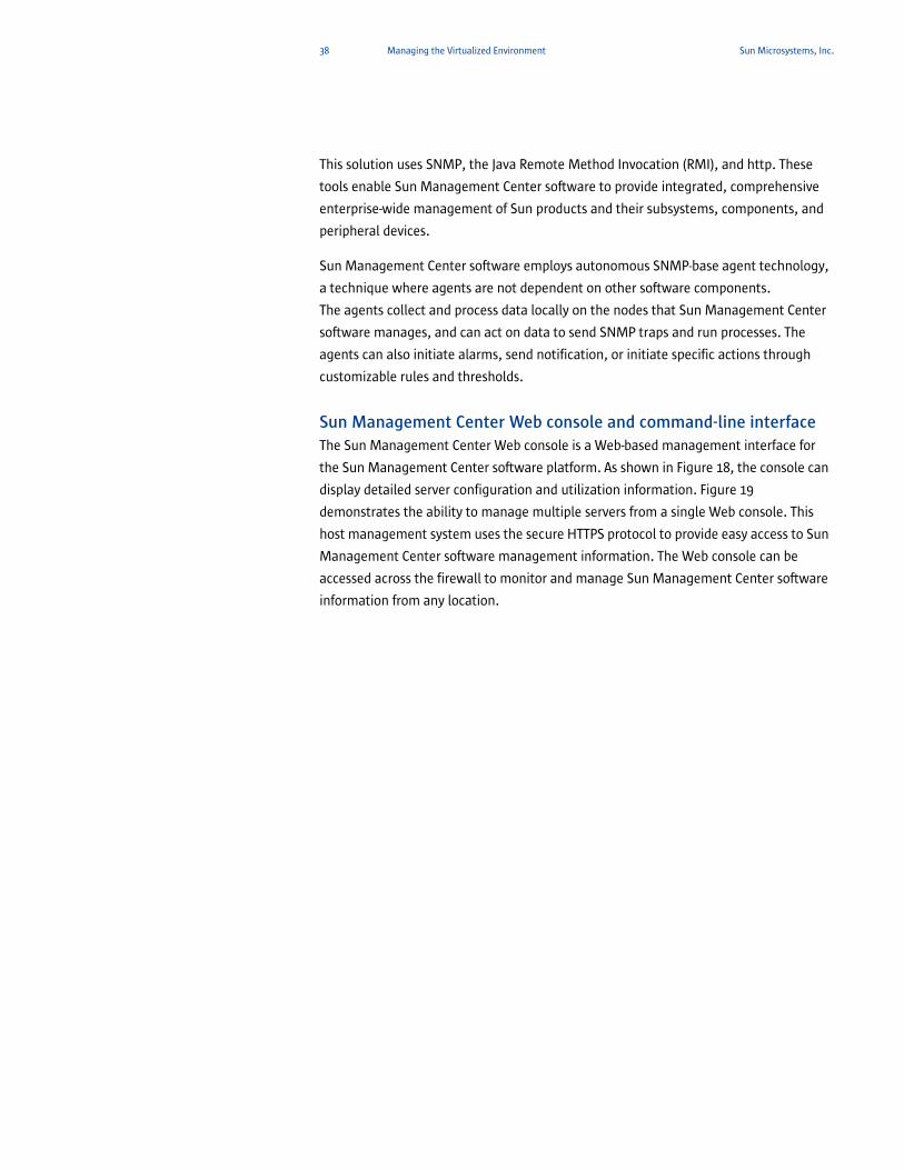
38 Managing the Virtualized Environment Sun Microsystems, Inc.
This solution uses SNMP, the Java Remote Method Invocation (RMI), and http. These
tools enable Sun Management Center software to provide integrated, comprehensive
enterprise-wide management of Sun products and their subsystems, components, and
peripheral devices.
Sun Management Center software employs autonomous SNMP-base agent technology,
a technique where agents are not dependent on other software components. The agents collect and process data locally on the nodes that Sun Management Center
software manages, and can act on data to send SNMP traps and run processes. The
agents can also initiate alarms, send notification, or initiate specific actions through
customizable rules and thresholds.
Sun Management Center Web console and command-line interfaceThe Sun Management Center Web console is a Web-based management interface for
the Sun Management Center software platform. As shown in Figure 18, the console can
display detailed server configuration and utilization information. Figure 19
demonstrates the ability to manage multiple servers from a single Web console. This
host management system uses the secure HTTPS protocol to provide easy access to Sun
Management Center software management information. The Web console can be
accessed across the firewall to monitor and manage Sun Management Center software
information from any location.
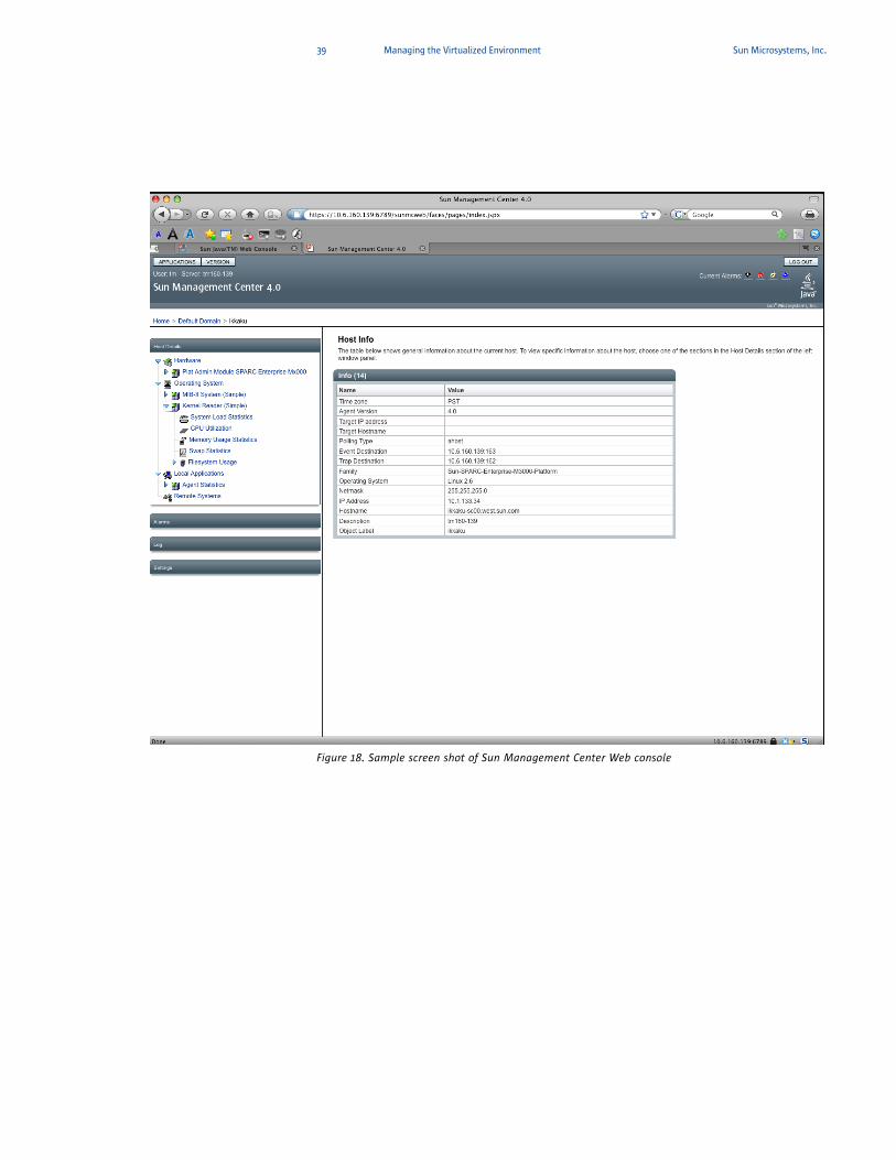
39 Managing the Virtualized Environment Sun Microsystems, Inc.
Figure 18. Sample screen shot of Sun Management Center Web console
40 Managing the Virtualized Environment Sun Microsystems, Inc.
Figure 19. Multiple servers can be managed from a single Sun Management Center Web console
The Web console is an optional Sun Management Center software component and
depends on the Sun Management Center server for retrieving and manipulating
managed objects. Many of the same host management functions offered by the Sun
Management Center Java Console are available within the Sun Management Center
Web console. The console supports widely available browsers, such as Mozilla 1.4 or
higher, Netscape Navigator™ 4.5.1 or higher, and Internet Explorer 5.0 or higher.
The Sun Management Center CLI is a character-driven console application for
monitoring and managing the system. The CLI offers low overhead for use on simple
data terminal equipment. Sun Management Center CLI provides a set of commands
that are a subset of the functionality provided by the GUI console.
41 Managing the Virtualized Environment Sun Microsystems, Inc.
Sun Management Center software offers additional valuable capabilities through the
following add-on components:
• Advanced System Monitoring — supports more complete system monitoring with
the following modules Directory Size Monitoring, Fault Manager, File Scanning,
Hardware Diagnostic Suite Health Monitor, Kernel Reader, Process Monitoring, and
Service Management Facility.
• System Reliability Manager — includes additional capabilities to help proactively
monitor and manage Sun servers and the Solaris OS, including patch monitoring, file
change monitoring, script repository and launch management, operating system
crash dump analyzer, and installed packages auditor.
• Performance Reporting Manager — utilizes the historical logging capability of Sun
Management center software to create reports detailing the status of systems. The
software includes 16 standard reports for which the report options are predefined.
Custom reports can be created by selecting options from the provided report
templates.
• Service Availability Manager — increases the availability of network services running
locally or remotely on Sun systems by continuously measuring and validating the
delivered quality of service.
• Solaris Container Manager — provides important features to help manage a
virtualized environment. Detailed information on Solaris Container Manager is
included in the following section.
Solaris Container ManagerSolaris Container Manager is an add-on component for Sun Management Center
software. This software helps consolidate servers to control the cost of large networks
of servers and software. The user interface for Sun Management Center software (4.0)
is integrated with Solaris Container Manager 4.0 through a common Sun Web console
user interface. As a result, the Solaris Container Manager user interface is not available
as a separate Web console. This functionality is available as the Manage Solaris
Containers tab in the Sun Management Center integrated Web application, promoting
smoother integration between the Solaris Container Manager and the Sun
Management Center software. An example of the Solaris Container Manager user
interface is shown in Figure 20.
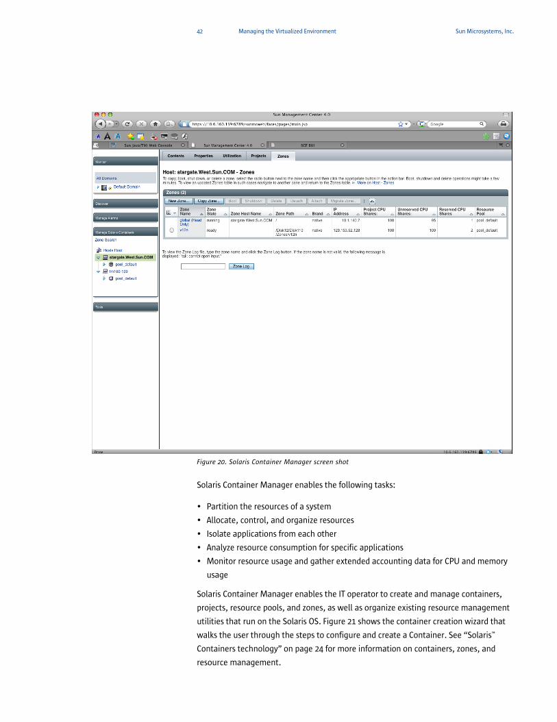
42 Managing the Virtualized Environment Sun Microsystems, Inc.
Figure 20. Solaris Container Manager screen shot
Solaris Container Manager enables the following tasks:
• Partition the resources of a system
• Allocate, control, and organize resources
• Isolate applications from each other
• Analyze resource consumption for specific applications
• Monitor resource usage and gather extended accounting data for CPU and memory
usage
Solaris Container Manager enables the IT operator to create and manage containers,
projects, resource pools, and zones, as well as organize existing resource management
utilities that run on the Solaris OS. Figure 21 shows the container creation wizard that
walks the user through the steps to configure and create a Container. See “Solaris™
Containers technology” on page 24 for more information on containers, zones, and
resource management.
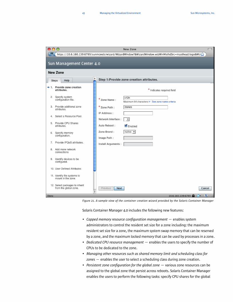
43 Managing the Virtualized Environment Sun Microsystems, Inc.
Figure 21. A sample view of the container creation wizard provided by the Solaris Container Manager
Solaris Container Manager 4.0 includes the following new features:
• Capped memory resource configuration management — enables system
administrators to control the resident set size for a zone including: the maximum
resident set size for a zone, the maximum system swap memory that can be reserved
by a zone, and the maximum locked memory that can be used by processes in a zone.
• Dedicated CPU resource management — enables the users to specify the number of
CPUs to be dedicated to the zone.
• Managing other resources such as shared memory limit and scheduling class for
zones — enables the user to select a scheduling class during zone creation.
• Persistent zone configuration for the global zone — various zone resources can be
assigned to the global zone that persist across reboots. Solaris Container Manager
enables the users to perform the following tasks: specify CPU shares for the global
44 Managing the Virtualized Environment Sun Microsystems, Inc.
zone, specify dedicated CPUs for the global zone, specify capped memory resource
configuration for the global zone, specify maximum shared memory, and change the
pool for the global zone.
If the Performance Reporting Manager add-on is installed with the Solaris Container
Manager, the IT operator can create reports that provide historical resource utilization
data per container, resource pool, zone, project, or system. CPU data, memory
utilization data, and CPU extended accounting data are stored in the database by the
Performance Reporting Manager data collection service. From the GUI, a graph report
detailing resource usage can be requested, or the data can be exported to a text file in
comma-separated value (CSV) format.
Solaris Management ConsoleSolaris Management Console makes it easy for IT operators to configure and manage
systems running the Solaris OS. Based on Java technology, the Solaris Management
Console is a container for GUI-based management tools that are stored in collections
called toolboxes. The console includes a default toolbox with tools to manage users,
projects, and jobs for managing file system mounts, disks, and serial ports. The console
helps enable IT operators to easily view activity on all managed servers and modify
applications and services running on them. The Solaris Management Console also
delivers powerful capabilities to make the process of adding users, hosts, or
applications as simple as pointing and clicking from any client on the network.
The Solaris Management Console enables users and IT operators to register other
Solaris Management Console servers and applications on the network. It dynamically
configures a hierarchical or flat tree view of registered hosts and services when the
console is accessed, making it easier to manage each server.
The Solaris Management Console helps improve productivity for IT departments and
systems and network administrators by providing several important capabilities:
• Support for all experience levels — inexperienced IT operators can complete tasks by
using the GUI, which includes dialog boxes, wizards, and context help. Experienced
IT operators find that the console provides a convenient, secure alternative to using
vi.
• Administration tools that can be integrated and run from one location.
• Centralized management — all servers on a network can be managed.
• Single login into applications launched by the Solaris Management Console.
• Instant access to existing administration tools.
• Secure communication via support for https and SSL.
45 Managing the Virtualized Environment Sun Microsystems, Inc.
The Solaris Management Console also includes a set of graphically-based wizards to
streamline and simplify these complex or frequently performed administration tasks:
• Monitor and manage system information such as date, time, and time zone
• Monitor and manage system processes
• Monitor system performance
• Manage users, rights, roles, groups, and mailing lists
• Create and manage projects
• Manage patches
• Create and manage scheduled cron jobs
• Mount and share file systems
• Create and manage disk partitions, volumes, hot spare pools, state database
replicas, and disk sets
• Set up terminals and modems
• Create and monitor computer and network information
• Shut down and boot the system
SNMP serviceA Simple Network Management Protocol (SNMP) agent can be configured and enabled
on the Service Processor, allowing the system to be monitored by third party tools. The
Service Processor SNMP agent monitors the state of the system hardware and
domains, and exports the following information to an SNMP manager:
• System information such as chassis ID, platform type, total number of CPUs, and
total memory
• Configuration of the hardware
• Dynamic Reconfiguration information, including which domain-configurable units
are assigned to which domains
• Domain status
• Power status
• Environmental status
The Service Processor SNMP agent can supply system information and fault event
information using public MIBs. SNMP managers, for example, a third-party manager
application, use any Service Processor network interface with the SNMP agent port to
communicate with the agent. The SNMP agent supports concurrent access from
multiple users through SNMP managers.
46 Managing the Virtualized Environment Sun Microsystems, Inc.
SNMP can be configured using v1, v2, or v3. The XSCF supports 2 MIBs for SNMP:
• SP-MIB (XSCF extension MIB) —This is used to attain information on the status and
configuration of the platform. If there is a fault, it sends a trap with the basic fault
information.
• FM-MIB (Fault Management MIB) — This is used only when there is a fault. It sends
the fault trap, but includes all of the same detailed information as the Fault
Management Architecture (FMA) MIB in a Solaris domain. The information has the
data needed by the service technician when placing a service call. It is also useful if
the domain crashed due to a part failure.
There are two methods of FMA reporting on the XSCF: through SNMP and through the
DSCP to the affected domain. To have the XSCF report all platform faults through SNMP
using FMA descriptors, enable SNMP on the XSCF.
47 Conclusion Sun Microsystems, Inc.
Chapter 5
Conclusion
In today’s exceedingly competitive environment, every IT department operates under
the mandate to reduce costs, increase return on investment, and provide a more
consistent environment to support compliance initiatives. In addition, IT solutions must
be able to quickly adapt to changes in demand and business processes.
The Sun SPARC Enterprise M-Series servers are the most powerful and innovative
enterprise-class systems available from Sun today. With the ability to partition the
system into sub-board level domains, isolate applications into containers, and manage
resources with fine-grained and dynamic control, the systems are ideally suited for
consolidating applications and optimally virtualizing and utilizing resources.
GUI-based tools are included with Sun SPARC Enterprise M-Series servers for
administering, monitoring, and managing the hardware, operating system, storage,
and applications. These tools streamline and automate many tasks, thus decreasing
complexity and IT operations costs, while providing a more consistent environment.
ReferencesSun Microsystems posts product information in the form of data sheets, specifications,
and white papers on its Web site page at: http://www.sun.com/.
And on http://docs.sun.com:
• Sun SPARC Enterprise M8000/M9000 Systems Overview, Part No. 819-4204
• Sun SPARC Enterprise M4000/M5000 Servers Overview, Part No. 819-2204
• Sun SPARC Enterprise M4000/M5000/M8000/M9000 Servers Dynamic
Reconfiguration User’s Guide, Part No. 819-5992
• System Administration Guide: Solaris Containers, Resource Management, and Solaris
Zones, Part No. 819-2450
• Sun Management Center Document Collection
• Installing and Administering Solaris Container Manager 3.6.1, Part No. 819-5420
Driving Datacenter Efficiency Through Server and Application Consolidation On the Web sun.com
Sun Microsystems, Inc. 4150 Network Circle, Santa Clara, CA 95054 USA Phone 1-650-960-1300 or 1-800-555-9SUN (9786) Web sun.com
© 2009 Sun Microsystems, Inc. All rights reserved. Sun Microsystems, Inc. Sun, Sun Microsystems, the Sun logo, Java, Solaris, and SPARC Enterprise are trademarks or registered trademarks of Sun Microsystems, Inc. or its subsidiaries in the U.S. and other countries. All SPARC trademarks are used under license and are trademarks or registered trademarks of SPARC International, Inc. in the U.S. and other countries. Products bear-ing SPARC trademarks are based upon architecture developed by Sun Microsystems, Inc. Information subject to change without notice. Printed in USA 01/09