Driver Amplifier BFQ790 for GSM900 Cellular Repeater ... - Компэ눦 · Key performance...
15
1 Revision 2.0, 2016-01-15 About this document Scope and purpose Application note describes a driver amplifier circuit that uses Infineon’s medium-power SiGe bipolar transistor BFQ790. This driver amplifier is designed for GSM900 (cellular repeaters) appplications. 1. This application note presents the measurement results of a driver amplifier design for 900 MHz application purposes. 2. BFQ790 is a single stage driver amplifier provides high linearity and high gain. 3. Key performance paramerters achieved (at 915 MHz) a. Gain = 20 dB b. Input return loss = 11 dB c. Output return loss =10 dB d. Output P1dB = 27 dBm e. Output IP3 = 38.7 dBm Driver Amplifier BFQ790 for GSM900 Cellular Repeater Applications Application Note: AN460
Transcript of Driver Amplifier BFQ790 for GSM900 Cellular Repeater ... - Компэ눦 · Key performance...
1 Revision 2.0, 2016-01-15
About this document
Scope and purpose
Application note describes a driver amplifier circuit that uses Infineon’s medium-power SiGe bipolar
transistor BFQ790. This driver amplifier is designed for GSM900 (cellular repeaters) appplications.
1. This application note presents the measurement results of a driver amplifier design for 900 MHz
application purposes.
2. BFQ790 is a single stage driver amplifier provides high linearity and high gain.
3. Key performance paramerters achieved (at 915 MHz)
a. Gain = 20 dB
b. Input return loss = 11 dB
c. Output return loss =10 dB
d. Output P1dB = 27 dBm
e. Output IP3 = 38.7 dBm
Driver Am pli f ier B FQ 790 for G S M9 00
Cel l ular R epea ter Ap pl i ca t i on s
A p p l i c a t i o n N o t e : A N 4 6 0

BFQ790 Driver Amplifier for GSM900 Application
Application Note AN460 2 Revision 2.0, 2016-01-15
Table of Contents
Table of Contents ........................................................................................................................ 2
List of Figures ............................................................................................................................. 3
1 Introduction ............................................................................................................... 4 1.1 BFQ790 as Driver Amplifier for GSM900 Cellular Repeaters .............................................................. 4
1.2 Infineon Driver Amplifier Family ......................................................................................................... 5
2 Driver Amplifier BFQ790 for GSM900 Cellular Repeater Applications ................................ 6 2.1 Performance Overview ........................................................................................................................ 6
3 Measurement Graphs .................................................................................................. 8
4 Evaluation Board and Layout Information ................................................................... 13
5 Authors .................................................................................................................... 14

BFQ790 Driver Amplifier for GSM900 Application
Application Note AN460 3 Revision 2.0, 2016-01-15
List of Figures
Figure 1 Schematic of the BFQ790 Application Circuit for GSM900................................................................. 7 Figure 2 Insertion Power Gain of the BFQ790 Driver Amplifier ........................................................................ 8 Figure 3 Input Matching of the BFQ790 Driver Amplifier ................................................................................. 8 Figure 4 Input Matching of the BFQ790 Driver Amplifier ................................................................................. 9
Figure 5 Output Matching of the BFQ790 Driver Amplifier............................................................................... 9 Figure 6 Output Matching of the BFQ790 Driver Amplifier............................................................................. 10 Figure 7 Reverse Isolation of the BFQ790 Driver Amplifier ............................................................................ 10
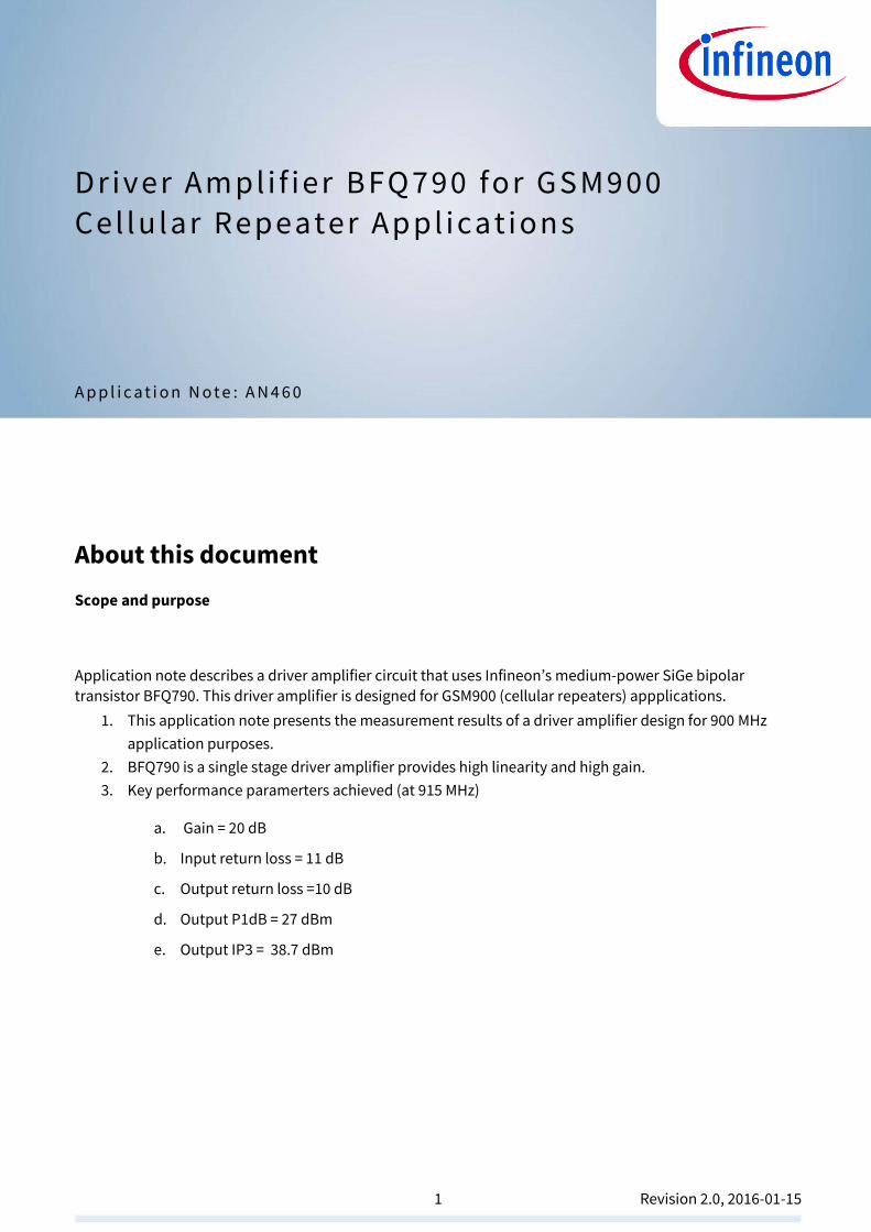
Figure 8 Output 1dB Compression Point ........................................................................................................ 11 Figure 9 Carrier to IM3 Ratio of the BFQ790 Driver Amplifier ......................................................................... 11
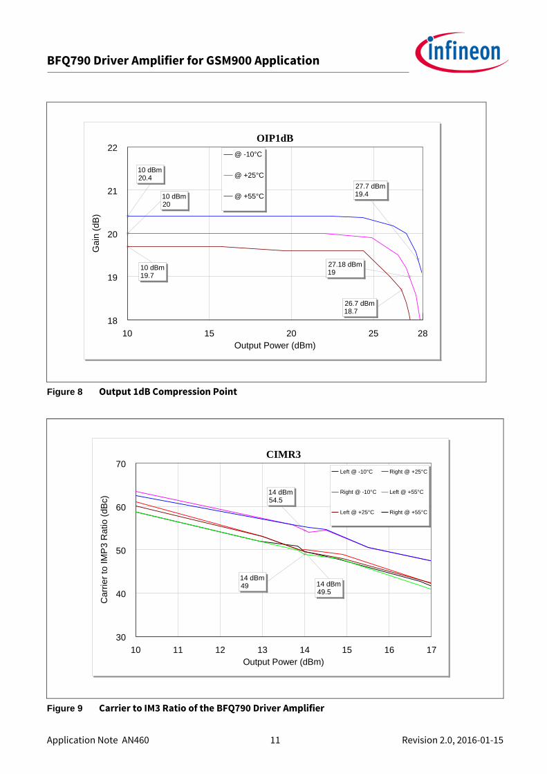
Figure 10 Stability Mu1, Mu2 - factors of the BFQ790 Driver Amplifier ............................................................ 12
Figure 11 Photo of Evaluation Board (overview).............................................................................................. 13 Figure 12 Photo of Evaluation Board (detailed view) ...................................................................................... 13
List of Tables
Table 1 Summary of Measurement Results ..................................................................................................... 6 Table 2 Bill-of-Materials ................................................................................................................................... 7
1) The graphs are generated with the simulation program AWR Microwave Office®.

BFQ790 Driver Amplifier for GSM900 Application
Application Note AN460 4 Revision 2.0, 2016-01-15
1 Introduction
1.1 BFQ790 as Driver Amplifier for GSM900 Cellular Repeaters
In the procedure normally used for effecting radio transmissions between base stations and cellpnes, when the strength of the signal from the base station falls below minimum levels (as the mobilephone moves from
one point to another), the mobilephone does not transfer the transmission in progress to another station without interruption. Now, thanks to the capability of transmitting data between bas station and mobile
phones, a transmission can be transferred without interruption from a base station to an adjacent fixed station which is closer to the mobile phone. Besides an insufficient number of cells, the following factors - Road, railway and subway tunnels - Buildings that are especially well-shielded - Radio-electric shadow areas (city centres) - Mountainous or hilly areas - Zones without cells, where the coverage is necessarily limited. The situation involving tunnels is the most
clear-cut case. The other cases can be resolved by increasing the density of the cells; however, this solution may not be advantageous because the radio-frequency signals may be reflected (especially in mountainous or shadow areas), which causes spurious handovers and probable losses of transmissions.
As was described above, the coverage limits of radio base stations can be extended by using cellular
repeaters that retransmit a band of carriers from the nearest radio base station into the area or environment
to be served. The simplest method for reaching this goal is to use a radio reception/transmission antenna pointed toward the nearest radio base station, a bi-directional amplifier and a radiating element (for example, an antenna) whose spatial transmission characteristics (range, angle of aperture and angle of
curvature) can be controlled sufficiently.
As can be seen in figure 1, an antenna-antenna type of cellular repeater system is made up of an RBS antenna, a radio-frequency amplifier and an RMA antenna.
The signal received by the RBS antenna (from the closest RBS, which is called the "donor RBS"), is amplified and sent to the RMA antenna, which is pointed toward the shadow area to be "illuminated". The signal from
the mobile station, which is received by the RMA antenna, is treated in the same way and sent to the donor
RBS.
RBS ANTENNA RMA ANTENNA
DUPLEXER DUPLEXER

BFQ790 Driver Amplifier for GSM900 Application
Application Note AN460 5 Revision 2.0, 2016-01-15
Figure 1 Bi-directional cellular repeater
1.2 Infineon Driver Amplifier Family
The driver amplifier, also known as a gain block, is an important functional block in RF transceiver systems requiring high output power. The Power Amplifier (PA), the final stage of a signal-amplifier chain, requires a certain input power level to operate in the linear mode, which usually cannot be delivered by the transceiver IC directly. In these cases, external one or two stage driver amplifiers are required. Driver amplifiers are
generally operated in linear Class-A mode to enable high linearity and high gain, thereby keeping spurious
signals generated by the PA low by reducing intermodulation products. Class-A amplifiers are also the right choice for broadband operation at low power levels.
BFQ790 and BFP780 are general-purpose medium-power transistors in Infineon’s Silicon Germanium (SiGe) product portfolio for wireless infrastructure applications. These applications include mobile basestation
transceivers, cellular repeaters, the industrial, scientic and medical (ISM) radio band amplifiers, and test equipment. Their operating frequency range can be as high as 3.6 GHz, and the application circuit can be
optimized for specific frequency bands with external matching components. The BFQ790 is a single-stage driver amplifier with very high linearity. Its output 1dB compression point is 27
dBm. The device is housed in the halogen-free industry-standard package SOT89. The high thermal conductivity of silicon substrate and the low thermal resistance of the package add up to a thermal
resistance of only 35 K/W, which leads to moderate junction temperatures even at high dissipated power values. The proper die attach with good thermal contact is 100% tested, so that there is minimum variation of thermal properties. The device is based on Infineon's reliable and cost-effective NPN SiGe technology
running in high volume. The collector design allows safe operation with 5 V supply voltage. The BFQ790 is
very rugged. A special collector design protects it from thermal runaway secondary breakdown, which makes it rugged when exposed to mismatch at the output. The special design of the emitter/base diode
makes it robust and allows for high maximum RF input power.
In this application note, the driver application cirucit of BFQ790 for ISM Band (890 - 960 MHz) and its
measurement results are presented. The BFQ790 driver provides 20 dB gain in the frequency range of 890 to 960 MHz. The output 1dB compression point (OP1dB) is 27 dBm measured at 915 MHz. Besides, in two-tone test with tone spacing of 1 MHz, the output third order intercept point (OIP3) reaches 38.75 dBm.

BFQ790 Driver Amplifier for GSM900 Application
Application Note AN460 6 Revision 2.0, 2016-01-15
2 Driver Amplifier BFQ790 for GSM900 Cellular Repeater
Applications
2.1 Performance Overview
Device: BFP740FESD
Application: Driver Amplifier BFQ790 for GSM900 Cellular Repeater Applications
PCB Marking: M15211
Table 1 Summary of Measurement Results
Parameter Symbol Value Unit Comments/Test Conditions
DC Voltage VCC 5 V
DC Current ICq 260 mA
Frequency Freq 890 - 960 MHz
Gain G 20 dB Vcc = 5 V, Icc = 260 mA, the PCB and
SMA losses (0.1 dB) are substracted.
Input Return Loss RLin 11.5 dB
Output Return Loss RLout 10 dB
Reverse Isolation IRev 30 dB
Output P1dB OP1dB 27 dBm Measured at 915 MHz
Output IP3 OIP3 38.7 dBm Power @ Input: 14 dBm
f1 = 915 MHz, f2 = 916 MHz
Stability µ1, µ2 > 1 -- Measured up to 10 GHz

BFQ790 Driver Amplifier for GSM900 Application
Application Note AN460 7 Revision 2.0, 2016-01-15
2.2 Schematic and Bill-of-Materials
Figure 1 Schematic of the BFQ790 Application Circuit for GSM900
Table 2 Bill-of-Materials
Symbol Value Unit Size Manufacturer Comment
Q1 BFQ790 SOT89 Infineon SiGe driver transistor
C1 8 pF 0402 Various Input matching & DC blocking
C2 5.6 pF 0402 Various Output matching & DC blocking
C3 47 nF 0402 Various RF bypass
C4 56 pF 0402 Various RF bypass
C5 10 nF 0402 Various RF bypass
L1 2 nH 0402 Murata LQG Input matching
L2 3 nH 0402 Murata LQG Input matching
L3 5.6 nH 0402 Murata LQG RF chock & Input matching
R1 100 Ω 0402 Various DC biasing
R2 400 Ω 0402 Various DC biasing

BFQ790 Driver Amplifier for GSM900 Application
Application Note AN460 8 Revision 2.0, 2016-01-15
3 Measurement Graphs
Figure 2 Insertion Power Gain of the BFQ790 Driver Amplifier
Figure 3 Input Matching of the BFQ790 Driver Amplifier
500 1000 1500 2000
Frequency (MHz)
Gain
-5
0
5
10
15
20
25
S2
1 (
dB
) 960 MHz19.29 dB
960 MHz19.7 dB
960 MHz20.11 dB
890 MHz19.38 dB
890 MHz19.82 dB
890 MHz20.24 dB
@ -10°C
@ +25°C
@ +55°C
500 1000 1500 2000
Frequency (MHz)
Input Return Loss
-25
-20
-15
-10
-5
0
5
10
S1
1 (
dB
)
960 MHz-11.45 dB
890 MHz-11.87 dB
960 MHz-11.57 dB
890 MHz-12.29 dB
960 MHz-11.73 dB
890 MHz-12.76 dB
@ -10°C
@ +25°C
@ +55°C

BFQ790 Driver Amplifier for GSM900 Application
Application Note AN460 9 Revision 2.0, 2016-01-15
Figure 4 Input Matching of the BFQ790 Driver Amplifier
Figure 5 Output Matching of the BFQ790 Driver Amplifier
0 1.0
1.0
-1.0
10.0
10.0
-10.0
5.0
5.0
-5.0
2.0
2.0
-2.0
3.0
3.0
-3.0
4.0
4.0
-4.0
0.2
0.2
-0.2
0.4
0.4
-0.4
0.6
0.6
-0.6
0.8
0.8
-0.8
Input MatchingSwp Max
1000MHz
Swp Min
800MHz
960 MHzr 0.642132x -0.230808
890 MHzr 0.920645x 0.442214
890 MHzr 0.919353x 0.46648
960 MHzr 0.642484x -0.244767
890 MHzr 0.915795x 0.489307
960 MHzr 0.644965x -0.259193
@ -10°C
@ +25°C
@ +55°C
500 1000 1500 2000
Frequency (MHz)
Output Return Loss
-20
-15
-10
-5
0
5
10
S2
2 (
dB
)
960 MHz-9.249 dB
890 MHz-14.4 dB
960 MHz-9.904 dB890 MHz
-14.6 dB
960 MHz-10.7 dB
890 MHz-14.85 dB
@ -10°C
@ +25°C
@ +55°C

BFQ790 Driver Amplifier for GSM900 Application
Application Note AN460 10 Revision 2.0, 2016-01-15
Figure 6 Output Matching of the BFQ790 Driver Amplifier
Figure 7 Reverse Isolation of the BFQ790 Driver Amplifier
0 1.0
1.0
-1.0
10.0
10.0
-10.0
5.0
5.0
-5.0
2.0
2.0
-2.0
3.0
3.0
-3.0
4.0
4.0
-4.0
0.2
0.2
-0.2
0.4
0.4
-0.4
0.6
0.6
-0.6
0.8
0.8
-0.8
Output MatchingSwp Max
1000MHz
Swp Min
800MHz
960 MHzr 0.67382x -0.363788
890 MHzr 1.33385x 0.227477
890 MHzr 1.37864x 0.18785
960 MHzr 0.633758x -0.375389
890 MHzr 1.41614x 0.139616
960 MHzr 0.5972x -0.380519
@ -10°C
@ +25°C
@ +55°C
0 2000 4000 6000 8000 10000
Frequency (MHz)
Reverse Isolation
-100
-80
-60
-40
-20
S1
2 (
dB
)
960 MHz-29.646 dB
890 MHz-30.321 dB
890 MHz-30.259 dB
960 MHz-29.637 dB
960 MHz-29.709 dB
890 MHz-30.293 dB
@ -10°C
@ +25°C
@ +55°C
BFQ790 Driver Amplifier for GSM900 Application
Application Note AN460 11 Revision 2.0, 2016-01-15
Figure 8 Output 1dB Compression Point
Figure 9 Carrier to IM3 Ratio of the BFQ790 Driver Amplifier
10 15 20 25 28
Output Power (dBm)
OIP1dB
18
19
20
21
22
Ga
in (
dB
)
26.7 dBm18.7
27.18 dBm19
27.7 dBm19.4
10 dBm19.7
10 dBm20
10 dBm20.4
@ -10°C
@ +25°C
@ +55°C
10 11 12 13 14 15 16 17
Output Power (dBm)
CIMR3
30
40
50
60
70
Carr
ier
to I
MP
3 R
atio
(dB
c) 14 dBm
54.5
14 dBm49.5
14 dBm49
Left @ -10°C
Right @ -10°C
Left @ +25°C
Right @ +25°C
Left @ +55°C
Right @ +55°C
BFQ790 Driver Amplifier for GSM900 Application
Application Note AN460 12 Revision 2.0, 2016-01-15
Figure 10 Stability Mu1, Mu2 - factors of the BFQ790 Driver Amplifier
100 2100 4100 6100 8100 10000
Frequency (MHz)
Stability
0
0.5
1
1.5
2
Mu
1, M
u2
Mu1 @ -10°C
Mu2 @ -10°C
Mu1 @ +25°C
Mu2 @ +25°C
Mu1 @ +55°C
Mu2 @ +55°C

BFQ790 Driver Amplifier for GSM900 Application
Application Note AN460 13 Revision 2.0, 2016-01-15
4 Evaluation Board and Layout Information In this application note, the following PCB is used:
PCB Marking: M15211
PCB material: FR4
r of PCB material: 4.6
Figure 11 Photo of Evaluation Board (overview)
Figure 12 Photo of Evaluation Board (detailed view)
Vias
Copper 35 µm,
FR4 Core, 510 µm
FR4 Preg, 360 µm

BFQ790 Driver Amplifier for GSM900 Application
Application Note AN460 14 Revision 2.0, 2016-01-15
5 Authors Dr. Olim Hidayov, RF Application Engineer of Business Unit “RF and Sensors”
Revision History
Major changes since the last revision
Page or Reference Description of change

Published by
Infineon Technologies AG
81726 Munich, Germany
© 2016 Infineon Technologies AG. All Rights Reserved.
Do you have a question about any
aspect of this document?
Email: [email protected]
Document reference
Legal Disclaimer THE INFORMATION GIVEN IN THIS APPLICATION NOTE (INCLUDING BUT NOT LIMITED TO CONTENTS OF REFERENCED WEBSITES) IS GIVEN AS A HINT FOR THE IMPLEMENTATION OF THE INFINEON TECHNOLOGIES COMPONENT ONLY AND SHALL NOT BE REGARDED AS ANY DESCRIPTION OR WARRANTY OF A CERTAIN FUNCTIONALITY, CONDITION OR QUALITY OF THE INFINEON TECHNOLOGIES COMPONENT. THE RECIPIENT OF THIS APPLICATION NOTE MUST VERIFY ANY FUNCTION DESCRIBED HEREIN IN THE REAL APPLICATION. INFINEON TECHNOLOGIES HEREBY DISCLAIMS ANY AND ALL WARRANTIES AND LIABILITIES OF ANY KIND (INCLUDING WITHOUT LIMITATION WARRANTIES OF NON-INFRINGEMENT OF INTELLECTUAL PROPERTY RIGHTS OF ANY THIRD PARTY) WITH RESPECT TO ANY AND ALL INFORMATION GIVEN IN THIS APPLICATION NOTE.
Information For further information on technology, delivery terms and conditions and prices, please contact the nearest Infineon Technologies Office (www.infineon.com).
Warnings Due to technical requirements, components may contain dangerous substances. For information on the types in question, please contact the nearest Infineon Technologies Office. Infineon Technologies components may be used in life-support devices or systems only with the express written approval of Infineon Technologies, if a failure of such components can reasonably be expected to cause the failure of that life-support device or system or to affect the safety or effectiveness of that device or system. Life support devices or systems are intended to be implanted in the human body or to support and/or maintain and sustain and/or protect human life. If they fail, it is reasonable to assume that the health of the user or other persons may be endangered.
www.infineon.com
Trademarks of Infineon Technologies AG AURIX™, C166™, CanPAK™, CIPOS™, CIPURSE™, CoolGaN™, CoolMOS™, CoolSET™, CoolSiC™, CORECONTROL™, CROSSAVE™, DAVE™, DI-POL™, DrBLADE™, EasyPIM™, EconoBRIDGE™, EconoDUAL™, EconoPACK™, EconoPIM™, EiceDRIVER™, eupec™, FCOS™, HITFET™, HybridPACK™, ISOFACE™, IsoPACK™, i-Wafer™, MIPAQ™, ModSTACK™, my-d™, NovalithIC™, OmniTune™, OPTIGA™, OptiMOS™, ORIGA™, POWERCODE™, PRIMARION™, PrimePACK™, PrimeSTACK™, PROFET™, PRO-SIL™, RASIC™, REAL3™, ReverSave™, SatRIC™, SIEGET™, SIPMOS™, SmartLEWIS™, SOLID FLASH™, SPOC™, TEMPFET™, thinQ!™, TRENCHSTOP™, TriCore™.
Other Trademarks Advance Design System™ (ADS) of Agilent Technologies, AMBA™, ARM™, MULTI-ICE™, KEIL™, PRIMECELL™, REALVIEW™, THUMB™, µVision™ of ARM Limited, UK. ANSI™ of American National Standards Institute. AUTOSAR™ of AUTOSAR development partnership. Bluetooth™ of Bluetooth SIG Inc. CAT-iq™ of DECT Forum. COLOSSUS™, FirstGPS™ of Trimble Navigation Ltd. EMV™ of EMVCo, LLC (Visa Holdings Inc.). EPCOS™ of Epcos AG. FLEXGO™ of Microsoft Corporation. HYPERTERMINAL™ of Hilgraeve Incorporated. MCS™ of Intel Corp. IEC™ of Commission Electrotechnique Internationale. IrDA™ of Infrared Data Association Corporation. ISO™ of INTERNATIONAL ORGANIZATION FOR STANDARDIZATION. MATLAB™ of MathWorks, Inc. MAXIM™ of Maxim Integrated Products, Inc. MICROTEC™, NUCLEUS™ of Mentor Graphics Corporation. MIPI™ of MIPI Alliance, Inc. MIPS™ of MIPS Technologies, Inc., USA. muRata™ of MURATA MANUFACTURING CO., MICROWAVE OFFICE™ (MWO) of Applied Wave Research Inc., OmniVision™ of OmniVision Technologies, Inc. Openwave™ of Openwave Systems Inc. RED HAT™ of Red Hat, Inc. RFMD™ of RF Micro Devices, Inc. SIRIUS™ of Sirius Satellite Radio Inc. SOLARIS™ of Sun Microsystems, Inc. SPANSION™ of Spansion LLC Ltd. Symbian™ of Symbian Software Limited. TAIYO YUDEN™ of Taiyo Yuden Co. TEAKLITE™ of CEVA, Inc. TEKTRONIX™ of Tektronix Inc. TOKO™ of TOKO KABUSHIKI KAISHA TA. UNIX™ of X/Open Company Limited. VERILOG™, PALLADIUM™ of Cadence Design Systems, Inc. VLYNQ™ of Texas Instruments Incorporated. VXWORKS™, WIND RIVER™ of WIND RIVER SYSTEMS, INC. ZETEX™ of Diodes Zetex Limited. Last Trademarks Update 2014-07-17
Edition 2016-01-15
AN_201601_PL32_001