Driveline Torque Estimations for a Ground Vehicle with ...acl.kaist.ac.kr/Thesis/2017TVT_KSY.pdf ·...
13
1 Abstract—This study proposes a novel method for estimating driveline torques for a vehicle with a dual-clutch transmission (DCT). Knowledge of the driveline torque states, such as the torque transmitted through a clutch, and transmission output torque, allows a significant improvement in powertrain control performance, especially during gear shifts and vehicle launch. Furthermore, vehicles with DCT or automatic transmission whose gear shift processes involve clutch-to-clutch shifts require information about the individual clutch torques for sophisticated torque transfer control. Thus, an adaptive torque observer, which is applicable to DCT drivelines, is developed to estimate the torque transmitted through each clutch and output shaft simultaneously. In order to overcome the lack of measurements in a production car, the proposed observer uses multiple adaptation laws in accordance with driving conditions so that it treats parameter uncertainties effectively, such as those of the clutch friction coefficient, nominal engine torque as well as vehicle load torque. Also, the observer is characterized by its simple and intuitive structure based on a reduced order driveline model. The estimation performance of the observer including its robustness to the parameter errors is evaluated not only by simulations but also by experiments under various driving scenarios. Index Terms—Dual clutch transmission, clutch torque estimation, output shaft torque estimation, engine torque correction, adaptive observer I. INTRODUCTION ual-clutch transmissions (DCTs) have received considerable attention in the global automotive industry, and have provided significant improvements in both the efficiency and ride quality of vehicles. DCTs are equipped with two sets of clutches and transfer shafts to transmit the engine torque to the axle, which can effectively eliminate the drawbacks of manual transmissions (MTs) and automated manual transmissions (AMTs) during gear shifts; that is, such configurations lead to a significant reduction in torque discontinuities and interruptions. DCTs also provide significantly higher efficiency than conventional planetary-type automatic transmissions (ATs) [1]. However, DCTs are more likely to produce awkward shift shocks during gear shifts because there is no smoothing effect from torque converters [2]. Recently, in recognition of its advantages, the S. Kim and S. B. Choi are with the Department of mechanical engineering, Korea Advanced Institute of Science and Technology, Daejeon 34141, South Korea (e-mail: [email protected]; [email protected]) J. J. Oh is with Eco-vehicle Control System Development Team, Hyundai Motor Company, 150 Hyundaeyeonguso-ro, Hwaseong-si, Gyeonggi-do 18280, South Korea (e-mail: [email protected]) application of DCTs has been extended to production hybrid electric vehicles [3, 4]. For stepped ratio transmissions including AT, AMT, and DCT, desired shift performance is achievable only through the sophisticated control of the clutch(es) and engine to ensure smooth and fast torque transfer through the vehicle drivelines [5]. A control strategy using torque feedback information can be the most effective approach to accurately control the torque delivery, because real-time monitoring of driveline torque states facilitates the direct control of shift quality, as well as powertrain oscillations. Although alternative torque controllers using information like the actuator position or clutch pressure can also be implemented, the effects of thermal expansion and clutch wear on clutch torque transmissibility degrades their control performance significantly [6, 7]. In fact, much of the literature on DCT shift control has adopted torque-based control strategies in order to achieve the pre-determined shift requirements [8-13]. However, torque sensors are not installed in production vehicle powertrains because of their high costs and spatial limitation. Many previous studies have attempted to resolve the need for torque sensors by proposing various torque estimation methods, especially for vehicles with AT or AMT. A reduced-order observer was proposed to estimate the output shaft torque of an AMT considering its nonlinear characteristics in [14], and another observer of the output shaft torque was designed for precise clutch engagement control by discriminating two phases of clutch: stick and slip in [15]. For AT equipped drivelines, various methods of estimating turbine torque have been investigated in [16-18], and in [19, 20], the authors introduced nonlinear sliding mode observers to estimate the output shaft torque. Ibamoto et al. compared two methods for estimating output shaft torque, based on the characteristics of the engine torque map and turbine torque map, respectively [21]. However, the aforementioned estimation methods are not suitable for DCTs, where the simultaneous operation of two clutches is involved in gear shifting, and no torque converter is installed. There have been a few studies reporting on torque estimation methods for DCTs. Some papers have proposed torque estimation methods for DCT drivelines [22-24] but the applicability of those approaches is limited to vehicle launch in which only one clutch was operated. More recently, a high-order sliding mode observer was developed to estimate the torque transmitted through each clutch during the launch, which involved the concurrent operations of two clutches [25]. Driveline Torque Estimations for a Ground Vehicle with Dual-clutch Transmission Sooyoung Kim, Jiwon J. Oh and Seibum B. Choi, Member, IEEE D
Transcript of Driveline Torque Estimations for a Ground Vehicle with ...acl.kaist.ac.kr/Thesis/2017TVT_KSY.pdf ·...
1
Abstract—This study proposes a novel method for estimating
driveline torques for a vehicle with a dual-clutch transmission (DCT). Knowledge of the driveline torque states, such as the torque transmitted through a clutch, and transmission output torque, allows a significant improvement in powertrain control performance, especially during gear shifts and vehicle launch. Furthermore, vehicles with DCT or automatic transmission whose gear shift processes involve clutch-to-clutch shifts require information about the individual clutch torques for sophisticated torque transfer control. Thus, an adaptive torque observer, which is applicable to DCT drivelines, is developed to estimate the torque transmitted through each clutch and output shaft simultaneously. In order to overcome the lack of measurements in a production car, the proposed observer uses multiple adaptation laws in accordance with driving conditions so that it treats parameter uncertainties effectively, such as those of the clutch friction coefficient, nominal engine torque as well as vehicle load torque. Also, the observer is characterized by its simple and intuitive structure based on a reduced order driveline model. The estimation performance of the observer including its robustness to the parameter errors is evaluated not only by simulations but also by experiments under various driving scenarios.
Index Terms—Dual clutch transmission, clutch torque
estimation, output shaft torque estimation, engine torque correction, adaptive observer
I. INTRODUCTION ual-clutch transmissions (DCTs) have received considerable attention in the global automotive industry, and have provided significant improvements in both the
efficiency and ride quality of vehicles. DCTs are equipped with two sets of clutches and transfer shafts to transmit the engine torque to the axle, which can effectively eliminate the drawbacks of manual transmissions (MTs) and automated manual transmissions (AMTs) during gear shifts; that is, such configurations lead to a significant reduction in torque discontinuities and interruptions. DCTs also provide significantly higher efficiency than conventional planetary-type automatic transmissions (ATs) [1]. However, DCTs are more likely to produce awkward shift shocks during gear shifts because there is no smoothing effect from torque converters [2]. Recently, in recognition of its advantages, the
S. Kim and S. B. Choi are with the Department of mechanical engineering, Korea Advanced Institute of Science and Technology, Daejeon 34141, South Korea (e-mail: [email protected]; [email protected])
J. J. Oh is with Eco-vehicle Control System Development Team, Hyundai Motor Company, 150 Hyundaeyeonguso-ro, Hwaseong-si, Gyeonggi-do 18280, South Korea (e-mail: [email protected])
application of DCTs has been extended to production hybrid electric vehicles [3, 4].
For stepped ratio transmissions including AT, AMT, and DCT, desired shift performance is achievable only through the sophisticated control of the clutch(es) and engine to ensure smooth and fast torque transfer through the vehicle drivelines [5]. A control strategy using torque feedback information can be the most effective approach to accurately control the torque delivery, because real-time monitoring of driveline torque states facilitates the direct control of shift quality, as well as powertrain oscillations. Although alternative torque controllers using information like the actuator position or clutch pressure can also be implemented, the effects of thermal expansion and clutch wear on clutch torque transmissibility degrades their control performance significantly [6, 7]. In fact, much of the literature on DCT shift control has adopted torque-based control strategies in order to achieve the pre-determined shift requirements [8-13]. However, torque sensors are not installed in production vehicle powertrains because of their high costs and spatial limitation.
Many previous studies have attempted to resolve the need for torque sensors by proposing various torque estimation methods, especially for vehicles with AT or AMT. A reduced-order observer was proposed to estimate the output shaft torque of an AMT considering its nonlinear characteristics in [14], and another observer of the output shaft torque was designed for precise clutch engagement control by discriminating two phases of clutch: stick and slip in [15]. For AT equipped drivelines, various methods of estimating turbine torque have been investigated in [16-18], and in [19, 20], the authors introduced nonlinear sliding mode observers to estimate the output shaft torque. Ibamoto et al. compared two methods for estimating output shaft torque, based on the characteristics of the engine torque map and turbine torque map, respectively [21]. However, the aforementioned estimation methods are not suitable for DCTs, where the simultaneous operation of two clutches is involved in gear shifting, and no torque converter is installed.
There have been a few studies reporting on torque estimation methods for DCTs. Some papers have proposed torque estimation methods for DCT drivelines [22-24] but the applicability of those approaches is limited to vehicle launch in which only one clutch was operated. More recently, a high-order sliding mode observer was developed to estimate the torque transmitted through each clutch during the launch, which involved the concurrent operations of two clutches [25].
Driveline Torque Estimations for a Ground Vehicle with Dual-clutch Transmission
Sooyoung Kim, Jiwon J. Oh and Seibum B. Choi, Member, IEEE
D

2
Estimation approaches for individual clutch torque were proposed using unscented Kalman filters in [26, 27], and a Takagi-Sugeno observer in [28].
A major shortcoming of the previously published works is that simultaneous estimation of each clutch torque and output shaft torque has rarely been studied. Knowledge of each clutch torque is necessary for robust actuation of the clutches in the presence of thermal expansion and clutch wear. Information on output shaft torque is also required for accurate powertrain controls, since it is directly related to the acceleration and jerk of the vehicle, affecting the ride quality. In [29, 30], novel estimators intended for all those torque states were established by combining multiple observers for each driveline component, but their structures are not simple enough to be used in practical applications. Hence, this paper develops a new torque observer for the simultaneous estimation of individual clutch torque and output shaft torque in DCT drivelines. The observer was implemented based on a reduced order model with practical concerns, using only the measurements already available in current production vehicles.
Another important problem arising in driveline torque estimations is the poor accuracy of nominal engine torque obtained from an engine control unit (ECU). It is generally known that nominal engine torque values are accurate in steady states, but its discrepancy from the actual engine torque particularly increases during severe transients, such as when the throttle position is significantly varied. Thus, the proposed observer also serves to correct the engine torque values using an adaptive algorithm for the shift phases, when the engine controller is activated. Accurate information about the net engine torque is also useful for air/fuel management control and for detecting engine misfires [31, 32].
The remainder of this paper is organized as follows. In Section II, a reduced order model of DCT drivelines is introduced. In Section III, the design procedure of the torque observer is presented, and its estimation strategy is also explained in detail. In Section IV, the feasibility and effectiveness of the proposed torque estimator are evaluated through various simulations using a high-fidelity SimDriveline model. In Section V, the estimating performance of the observer is experimentally verified using a real vehicle as well as a DCT test-bench equipped with torque sensors. A detailed discussion of the results is also presented. Finally, this study is concluded in Section VI.
II. MODEL DEVELOPMENT
A. Driveline model A driveline with DCT has a structure similar to those with an MT or an AMT, but it is equipped with one more set of input and transfer shafts. The driveline model consists of several angular speed dynamics developed by using the torque balance relationships for the lumped inertias of the individual components. The 6th order dynamics are presented in this section to demonstrate the structure of DCT driveline [29], as depicted in Fig.1. Here, the variables w , q , J , and T denote angular speed, rotation angle, inertia, and torque, respectively.
Fig. 1. DCT driveline model structure The subscripts e , d , 1c , 2c , 1t , 2t , o , w , and v stand for engine, damper, input shaft with clutch 1, input shaft with clutch 2, transfer shaft 1, transfer shaft 2, output shaft, wheel, and vehicle. Assuming the behavior of a dual-mass flywheel is represented as a torsional damper, the speed dynamics of the engine and the torsional damper are described in (1) and (2).
,e e e dJ T Tw = -& (1)
1 2 ,d d d c cJ T T Tw = - -& (2) The torque transmitted through the torsional damper is modelled as (3),
( ) ( ) ,d d e d d e dT k bq q w w= - + - (3) where dk and dc are the torsional stiffness and damping coefficient of the damper, respectively. Denoting the equivalent inertias seen by clutch 1 and clutch 2 for the components, including the input and transfer shafts, gears, and synchronizers as 1ctJ and 2ctJ , the dynamics of each transfer shaft are presented in (4) and (5), as follows:
11 1 1
1
,tct c c
t
TJ Ti
w = -& (4)
22 2 2
2
,tct c c
t
TJ Ti
w = -& (5)
where 1ti is the gear ratio of the input and transfer shaft 1, and
2ti is that of the input and transfer shaft 2. The transmitted torque through each clutch is described as (6) and (7), depending on the states of the clutches [33]:
( )1 1 1 1 1 1
1 2
0 if disengagedsgn if slipping
, if engagedc k n c d c
in d c d d
T F r N
T T T J
m w w
w
ìï
= -íï - -î &@
(6)
( )2 2 2 2 2 2
2 1
0 if disengagedsgn if slipping
, if engagedc k n c d c
in d c d d
T F r N
T T T J
m w w
w
ìï
= -íï - -î &@
(7)
where km , nF , cr and N are kinetic friction coefficient, actuator normal force, effective torque radius, and number of friction surfaces of each clutch, respectively. The dynamics of the output shaft and wheel are also described in (8) and (9) using the principle of torque balance.
1 1 2 2 ,o o f t f t oJ i T i T Tw = + -& (8) ,v w o vJ T Tw = -& (9)
where oT stands for the output shaft torque, and vT the vehicle load torque. The output shaft torque can be expressed as (10) using the torsional compliance model.

3
( ) ( ) ,o o o w o o wT k bq q w w= - + - (10) where ok and oc are the torsional stiffness and damping coefficient of the output shaft, respectively. The load torque influenced by road inclination, aerodynamic drag, and rolling resistance can be calculated by (11):
( ) 21sin .2v v air v D v rr wT M g A C V M gC rj ræ ö= + +ç ÷
è ø (11)
In (11), vM , j , airr , vA , DC , V , rrC and wr denote vehicle mass, angle of road inclination, air density, vehicle frontal area, drag coefficient, vehicle speed, rolling resistance coefficient, and wheel radius.
B. Reduced Order Model with Practical Concerns For practical control applications, it is necessary to further
simply the driveline model, since many of the variables in (1)-(11) are not measured in production vehicles. Thus, the reduced order model considering practicality is developed as follows:
( )
_ 1 2
1_ 1 1 1 1 2 2 2
_
2
2 21_ 1 1 1 2
1 1 1 1
where ,
1 .
e eq e e c c
ct eq c t f c t f c o
v w o v
e eq e d
t fct eq t f ct ct o
t f t f
J T T TJ i i T i i T TJ T T
J J J
i iJ i i J J J
i i i i
w
w
w
= - -
= + -
= -
= +
æ öç ÷= + +ç ÷è ø
&&
& (12)
In (12), the compliances of the torsional damper and the input/transfer shafts are ignored such that the order of the model is reduced significantly, leaving only measurable states.
1_ct eqJ is the equivalent inertia from the clutch 1 perspective, and contains the inertias of all the components rotating synchronously with input shaft 1. The equivalent inertia seen by clutch 2 can be alternatively used in the reduced order model, provided that 1cw is replaced by 2cw in (12). One strong feature of the reduced order model is that it works for all general driving conditions including gear shifts and vehicle launch without any structural change.
III. TORQUE ESTIMATION STRATEGY
A. Overview The main objective of this study is to develop a practical estimator for the torque transmitted through each clutch, as well as the output shaft torque in a dry DCT driveline. In this study, the driveline torque estimation will be conducted by focusing on the characteristics of the gear shift process, where both clutches operate concurrently. This further complicates the control and state estimation problems. Specifically, gear shifts in vehicles with DCT are performed through the handover of the engine torque from one clutch to the other clutch, i.e., a clutch-to-clutch shift. A major obstacle in the torque estimation is the lack of available torque sensors on a production vehicle. Even the nominal engine torque acquired from ECU is inaccurate during the transients like gear shifts. Since engine control is generally activated during gear shifts to compensate
Fig. 2. Reduced order model structure for torque fluctuations produced by the abrupt gear ratio change, and the inertia effect [34, 35], the nominal engine torque during the shifting transients is much less accurate than any other driving conditions. A gear shift process of DCT is divided into two phases: the torque phase, where the torque is transmitted from the off-going clutch to the on-coming clutch; and the inertia phase, where the on-coming clutch is synchronized with the engine. In the driveline torque estimation, it is important to take into account the characteristics of each shift phase. An estimation method that is robust to the parametric uncertainties of both clutches is highly required in the torque phase because both clutch torques have a significant influence on the whole driveline dynamics. In the inertia phase, one of the clutches is disengaged, so that the transmitted torque through it simply becomes zero, but the engine control is activated, which produces a large uncertainty in the nominal engine torque. In order to manage the parametric uncertainties effectively, after considering such physical properties, the proposed torque estimator takes the form of an adaptive observer that uses several adaptation laws depending on the driving conditions. Also, the torque observer is developed based on the simplified driveline model (12) with practical aspects, and its performance is independent of the dynamics of other types of clutch actuators. The detailed design procedure of the driveline torque estimator will be introduced in the following sub-sections.
B. Torque Observer Design 1) State observer for output shaft torque By adding a new state for output shaft torque to (12), the state observer is designed as (13):
( ) ( )
( ) ( )
( ) ( )
( ) ( )
1 2 1_
1 1 1 1 2 2 2 2 1 11_
3
_ 4 1 1 5
1 ˆ ˆ ˆˆ ˆ
1 ˆ ˆ ˆˆ ˆ
1 ˆ ˆˆ ˆ
ˆ ˆ ˆ ,
e e c c e ee eq
c t f c t f c o c cct eq
w o v w wv
o o m c c w w
T T T LJ
i i T i i T T LJ
T T LJ
T T L L
w w w
w w w
w w w
w w w w
= - - + -
= + - + -
= - + -
= - - + -
&
& &
&
& &
(13)
where 1L , 2L , 3L , 4L , and 5L are the observer gains to be designed. The torsional compliance model (14) is employed in the observer in order to improve its transient response.
1_ _
1 1
ˆ ˆ ,co m o eq w
t f
T ki iw w
æ ö-ç ÷ç ÷
è ø& @ (14)
where _o eqk is the equivalent stiffness of the output shaft in the reduced order model. Such a simple compliance model may be
4
vulnerable to the measurement error of speeds, but it has been validated that the shaft compliance information is useful for estimating the transient torque through the shaft [30]. It is worth noting that no derivative of the measured speed is used in (13) to avoid the adverse effects of measurement noise. 2) Adaptation law for individual clutch torque Although the clutch torque can be modelled by using (6)-(7), it is difficult to accurately identify the friction coefficient of the clutch, since it varies continuously with the temperature or slip speed of the clutch [6, 36, 37]. Another problem that arises when estimating the torque transmitted through a dry clutch is that the clutch normal force cannot be measured, so it needs to be calculated as a function of the corresponding actuator position. Hence, an adaptation algorithm to treat such parametric uncertainties is designed in this sub-section. First, the clutch torque equations during slipping are arranged to explicitly exhibit the positions of the clutch actuators, as follows:
1 1 1 1 1 1 1 1 1 1,c k n c k f m cT F r N k r Nm m q= = (15)
2 2 2 2 2 2 2 2 2 2 ,c k n c k f m cT F r N k r Nm m q= = (16) where 1mq , 2mq are the positions of the clutch actuators, and
1fk , 2fk the force transmissibility coefficients used to define
relationships between the actuator position and the normal force of each clutch. In general, the nominal values of
1fk , 2fk
at the corresponding actuator positions are obtained empirically from a powertrain test-bench, usually in the form of a force-position map. By defining the known nominal parts of the friction coefficient and force transmissibility coefficient as
,k nm and ,f nk , respectively, and the unknown parts as ˆkm and
ˆfk , (17) and (18) are derived.
( )( )( )1 1, 1 1, 1 1 1 1
1, 1, 1 1 1 1
1 1, 1 1 1, 1 1
ˆˆ
,
ˆ ˆˆ ˆwhere .
c k n k f n f m c
k n f n c m c
c k n f k f n k f
T k k r N
k r N
k k k
m m q
m t q
t m m m
= + +
= +
+ +@
(17)
( )( )( )2 2, 2 2, 2 2 2 2
2, 2, 2 2 2 2
2 2, 2 2 2, 2 2
ˆˆ
,
ˆ ˆˆ ˆwhere .
c k n k f n f m c
k n f n c m c
c k n f k f n k f
T k k r N
k r N
k k k
m m q
m t q
t m m m
= + +
= +
+ +@
(18)
Then, the adaptation laws for the unknown lumped parameters 1ct and 2ct are defined as (19) and (20):
( )1 1 41 1 1 1 1 1 1
_
ˆ ˆˆ 1 ,t fe ec c m c c c
e eq o
i i Lr N
J kw wt g q w w
æ öæ ö-- + + -ç ÷ç ÷ç ÷è øè ø
& @ (19)
( )2 2 2 2 42 2 2 2 2 1 1
_ 1 1
ˆ ˆˆ ,t f t fe ec c m c c c
e eq t f o
i i i i Lr N
J i i kw wt g q w w
æ öæ ö-- + + -ç ÷ç ÷ç ÷ç ÷è øè ø
& @
(20) where 1cg and 2cg refer to the adaptation gains that determine the adaptation rate. The adaptation laws update 1ct and 2ct in real time based on the current actuator positions and the estimation errors of the observer (13).
Note that the position information is only available if the transmission is fitted with dry type clutches. In the case of wet DCTs, the clutch pressure is often measured instead of the clutch position, and it can be used in the adaptation algorithm to correct the friction coefficient in the same manner as (19)-(20). 3) Adaptation law for engine torque Accurate knowledge of the engine torque is essential in any research related to powertrain management including driveline torque estimation. Since no sensor is available for engine torque in production vehicles, the nominal engine torque calculated from ECU is often used as the actual engine torque. However, the nominal engine torque is not accurate during the shift transient where the engine control is in effect. Thus, in this sub-section, another adaptation law is introduced to manage the inaccuracy of the nominal engine torque. The actual engine torque is represented as (21):
( ), 1 ,e e n eT T t= + (21) where ,e nT refers to the known nominal engine torque and et the unknown part. Then, an adaptation algorithm for et is designed as follows:
( ),_
1 ˆˆ .e e e n e ee eq
TJ
t g w w-& @ (22)
In (22), eg is the adaptation gain. The adaptation law updates
et based on the nominal engine torque and the engine speed error. 4) Adaptation law for vehicle load torque The vehicle load torque should also be known in real time for the driveline torque estimations. Since accurate measurement of the vehicle load torque is not possible, the vehicle load was roughly calculated using (11) under the assumption that
w wV r w» in many previous studies. However, the accuracy of (11) is highly vulnerable to its parameter uncertainties, so it cannot cover wide driving conditions. First, using (11), the nominal vehicle load is defined as follows:
2 2,
1 .2v n air v D w w v rr wT A C r M gC rr wæ ö= +ç ÷
è ø (23)
where V is approximated by w wr w , and the road inclination term is removed with 0f » . Assuming the vehicle load has a multiplicative uncertainty vt , the actual vehicle load can be represented as (24).
( ), 1 ,v v n vT T t= + (24) Then, the adaptation law for the load torque is designed as follows:
( ), ˆˆ 2 ,v v v n w wTt g w w- -& @ (25) where vg is the adaptation gain for (25). The adaptation law (25) updates the estimated load torque in real-time using the estimation error of the wheel speed.
C. Stability Analysis In order to prove the stability of the final adaptive torque observer, the following Lyapunov function candidate (positive definite and radially unbounded) is considered:

5
1_2 2 2 241 2 3 4
1 1 _ _
2 2 2 21 2
1 2
1 2 1 1 3
4 1 1 1 2 2 2
1 1 12 2 2
1 1 1 12 2 2 2
ˆ ˆ ˆwhere , , ,ˆ ˆ ˆ, , ,ˆ ˆ, .
ct eqv
t f o eq o eq
c c e vc c e v
e e c c w w
o o c c c c c c
e e e v v v
J LV Ji i k k
T T
e e e e
t t t tg g g ge w w e w w e w w
e t t t t t tt t t t t t
æ ö= + + + +ç ÷ç ÷
è ø
+ + + +
- - -
- - -
- -
% % % %
@ @ @
% %@ @ @% %@ @
(26)
The derivative of (26) with respect to time is presented as (27) assuming the torque parametric uncertainties are slowly varying, i.e., 1 2, , , 0c c e vt t t t »& & & & .
( )
41 1 1_ 2 2 3 3 4 4
1 1 _ _
1 1 2 21 2
1 , 1 1 1 1 2 2 2 2 1 1_
142
1 1 _
1 12
1 1 1 1ˆ ˆ ˆ ˆ
1
1
ct eq vt f o eq o eq
c c c c e e v vc c e v
e e n c c m c c me eq
t
t f o eq
LV J Ji i k k
T r N r N LJ
i iLi i k
e e e e e e e e
t t t t t t t tg g g g
e t t q t q e
e
æ ö= + + + +ç ÷ç ÷
è ø
- - - -
æ ö= - - -ç ÷ç ÷
è ø
æ ö+ +ç ÷ç ÷
è ø
& & & & &
& & & &% % % %
% % %
( )
( )
1 1 1 1 1 2 2 2 2 2 2 4
2 1_ 2
3 4 , 3 3
544 2 3
1 1 _ _
1 1 2 21 2
2
1 1
1 1 1 1ˆ ˆ ˆ ˆ
f c c m t f c c m
ct eq
v v n v
t f o eq o eq
c c c c e e v vc c e v
r N i i r N
L J
T L J
LLi i k k
t q t q e
e
e e t e
e e e
t t t t t t t tg g g g
æ ö+ -ç ÷ç ÷-è ø
+ - -
æ öæ ö æ ö+ + - +ç ÷ç ÷ ç ÷ç ÷ ç ÷ç ÷è ø è øè ø
- - - -
% %
%
& & & &% % % %
(27) If the observer and adaptation gains are chosen such that
1 2 3 4 1 2, , , , , , , 0,c c e vL L L L g g g g > and 5 _ ,o eqL k@ (27) becomes
(28) by substituting (19), (20), (22) and (25) into it.
2 2 241 1 2 1_ 2 3 3
1 1 _
1 2 0.ct eq vt f o eq
LV L L J L Ji i k
e e eæ ö
= - - + - £ç ÷ç ÷è ø
& (28)
The time derivative of V is negative semi-definite, which only guarantees the stability of the observer. In fact, it is not possible for the observer of the current form to always guarantee that all the estimated torque values are converged to the true values because the number of the estimated variables are larger than the number of available measurements. For example, since all the adaptation laws specified in (19), (20), and (22) use the estimation error of engine speed in common for parameter estimations, we cannot uniquely determine which parameter should be corrected to reduce the engine speed error. Thus, the following two assumptions are made to resolve the redundancy issue in the torque estimation: 1) The vehicle load remains unchanged during a gear shift. 2) The nominal engine torque is sufficiently reliable for the driveline torque estimation in normal driving conditions except for inertia phase of each gear shift. The first assumption indicates that the duration of a gear shift is quite short compared with the other driving conditions so that the load variation during the shift is negligible. Based on the assumption, the adaptation law for vehicle load (25) is intentionally set to be deactivated in every gear shift. Also, the
engine torque adaptation is set to be in effect only in inertia phases of gear shifts using the second assumption. The proposed torque estimation strategy is briefly explained in Table I, provided that driving conditions of a vehicle can be divided into five phases: idling, launch, acceleration/deceleration, torque phase and inertia phase.
TABLE I TORQUE ESTIMATION STRATEGY
(Clutch 1: off-going clutch, Clutch 2: on-coming clutch) Driving
conditions Number of clutch(es)
involved in torque transfer
Applicable
Assumptions
Estimation or
adaptation targets
Idling 0 1 2, , 0e c cT Tt =
,o vT T
Launch 1 2, 0e cTt = 1, ,c o vT T T
Acceleration/ Deceleration
1 2, 0e cTt = 1, ,c o vT T T
Gear shift
Torque phase
2 , 0e vTt =& 1 2, ,c c oT T T
Inertia phase
(mostly) 1 1, 0c vT T =& 2, ,e c oT T T
Note that in case of a down-shift, the order of torque and inertia phases may be differ from that of Table I, and the on-coming clutch torque is assumed to be zero in inertia phase, instead of the off-going one. However, regardless of the type of gear shift, the number of torque variables to be estimated is always the same as shown in the Table I. Next, in order to demonstrate the asymptotic stability of the torque observer, consider the following set:
{ }1 2 3 4 1 2 1 2 3, , , , , , , , , 0 ,c c e ve e e e t t t t e e eW = =% % % % (29) where 0V = . If the vehicle load variation is negligible, i.e. 0vt »% during gear shifts, and the nominal engine torque is sufficiently close to the actual engine torque, i.e. 0et »% in other than inertia phases, (whereas, in inertia phases, one of clutches is always disengaged if a separate shift controller works properly, i.e.,
1 2or 0c ct t »% % ), then the origin 1 2 3 4 1 2, , , , , , , 0c c e ve e e e t t t t =% % % % is the only invariant subset of (29). Thus, it is also guaranteed that the estimation errors of the torque observer are asymptotically converged to zero [38]. The aforementioned assumptions made for the stability proof may produce some estimation errors inevitably, but accurate estimation of the driveline torque states can be realized with the assumptions despite of the absence of available torque sensors. The driveline torque observer was designed to suit a clutch-to-clutch shift process, but it works for all general driving conditions including vehicle launch, normal driving without any clutch manipulation, up-shift, and down-shift. In addition, since the observer is based solely on the driveline dynamics, the torque estimation approach is suitable for general DCTs, irrespective of the clutch actuator type and dynamics. The final observer structure is schematically illustrated in Fig. 3.

6
Fig. 3. Torque observer structure
TABLE II SIMDRIVELINE MODEL PARAMETERS
Driveline parameters Vehicle parameters
1
2
1
1
2
0.20.0860.05770.0355
0.0421510154205315000
e
d
ct
ct
o
d
d
t
t
t
JJJJJkbkbk
=
=
=
=
=
=
=
=
=
=
2
1
2
1 2
1 2
1 2
1 2
1 2
5195205913.6882.580
4.119
0.1340.270.30
1.7747
t
o
o
t
t
f f
c c
k k
s s
w
bkbiii ir rN N
J
m mm m
=
=
=
=
=
= =
= =
= == =
= =
=
1600C 0.015C =0.4
31
0.3120
v
rr
D
v
air
w
M
A
rr
f
=
=
=
=
=
=
Units are SI derived.
(kg, N, m, rad, s)
D. Remarks on PE Condition One structural advantage of the proposed adaptive observer is that its estimation performance is independent of the persistence of excitation (PE) condition. The PE condition is a sufficient condition that the regressor (e.g., 1mq , 2mq in (19), (20) and ,e nT in (22)) should satisfy for the parameter convergence of an adaptive system (for details, see [38, 39]). However, the profile of a regressor in adaptive systems, where the control objective is to track desired signals, is generally determined by system control inputs and cannot be arbitrarily designed to meet the PE condition. Since the control inputs act on the system separately from the adaptation algorithm, the parameter convergence of the adaptive system is not always guaranteed. For this reason, the proposed torque observer was designed to have a novel structure, which achieves the asymptotic convergence of the parameters, regardless of the PE condition. The effectiveness of the torque observer was verified for various conditions through both simulations and experiments, as presented in the next sections.
(a)
(b)
Fig. 4. Simulation scenario: (a) clutch actuator position, (b) driveline speed.
IV. SIMULATIONS
A. Simulation Set-up In this section, several simulations were carried out to demonstrate the effectiveness of the proposed torque observer. The DCT powertrain model was developed using SimDriveline which is a high-fidelity commercial software for modeling and simulating vehicle powertrain systems. Essential vehicle components including engine and tires, as well as the basic mechanical parts, are also accurately modeled using SimDriveline. The parametric values used for the simulations are described in Table II.
B. Simulation Results The aim of the simulations was to verify the robustness of the proposed torque observer to various parametric uncertainties. Hence, the simulations were conducted for two cases of uncertainties, assigned to the unknown torque states, as shown in Table III. Because in real applications we only know the predetermined nominal values of those torque states, the task of the torque observer is to accurately estimate the difference between the nominal values and the actual ones, denoted as 1ct ,
2ct , et , and vt in real time. TABLE III
ASSIGNED UNCERTAINTIES FOR SIMULATIONS Simulated
case Parameter Nominal
value
Actual value
Assigned Uncertainty
1km 0.36 0.27 +33%
Case (1) 2km 0.18 0.27 -33%
et 0.25 0 +25%
1km 0.18 0.27 -33%
Case (2) 2km 0.36 0.27 +33%
et -0.25 0 -25%
angu
lar s
peed
(rad
/s)

7
It is worth noting again that the unknown clutch parameters 1ct and 2ct indicate the combined uncertainties of the friction coefficient and the force transmissibility of each clutch, and et ,
vt are the uncertainties of the nominal engine torque and the load torque. The driving conditions used for both simulation cases are shown in Fig. 4. Note that the driving conditions contain the modes of vehicle launch (1s~) and gear shift (1-2 upshift) (5.3s~). Fig. 5 compares the actual torque values and the ones predicted by the torque observer for case (1). To directly demonstrate the effectiveness of the adaptation algorithm, the torque values that were estimated solely using (6) and (7) with nominal parameter values (without adaptations) are also plotted in Fig. 5. Here, the nominal output torque was calculated using the values of both nominal clutch torques, gear ratios, the lumped inertia of the transmission part (Fig. 5(d)).
(a)
(b)
(c)
(d)
Fig. 5. Torque estimation in the simulated case (1): (a) engine torque, (b) clutch 1 torque, (c) clutch 2 torque, (d) output shaft torque. It can be noticed clearly in Fig. 5 that the torque observer estimates the true torque values accurately throughout all given driving conditions. At around 1s, the actuator position of clutch
1 started to increase for vehicle launch (Fig. 4(a)), and the torque transmitted through it also increased accordingly (Fig. 5(b)). During the slipping of the clutch, the inaccuracies of its kinetic friction coefficient and force transmissibility have direct adverse effects on the torque estimation. Thus, in Fig. 5(b), a large discrepancy was found between the nominal torque without adaptations and the actual one, whereas the estimated torque with adaptations was very close to the actual one. Even after the clutch was completely engaged (1.5s~), the predicted values provided by the torque observer still followed the actual values rapidly. After 5.3s, a cross-shift of the two clutches was performed for the 1-2 upshift, in which the (off-going) clutch 1 torque was decreased, and the (on-coming) clutch 2 torque was increased. The torque phase of the shift, where the torque handover actually occurs between the two clutches, exists in every gear shift through DCTs (or ATs) and its characteristic is the main obstacle to estimating the torque of the DCT drivelines accurately. However, both clutch torques and the output shaft torque were estimated simultaneously with high precision by the proposed observer. Once clutch 1 began to slip, the inertia phase started immediately (at around 5.45s). Because the inertia phase generally induces large uncertainties in the nominal engine torque, the adaptation algorithm for the engine torque was also activated in the inertia phase. In the results, it can also be observed in Fig. 5(a) that the engine torque, which varied significantly due to the action of the separate engine controller, was well estimated by the torque observer. In Fig. 5(d), the nominal output torque with no adaptation showed a significant error, mainly caused by the inaccuracy of the system nominal parameters. At the moment of clutch engagement (e.g. around 1.5s), in particular, it exhibited largely oscillatory responses, which is unrealistic. This demonstrates that the driveline torque states are highly coupled one another, so accurate knowledge of the variable parameters such as clutch friction coefficient is crucial for the torque estimation. In the transients of vehicle launch and shift, considerable torque fluctuations occurred along the driveline. In particular, a large overshoot and undershoot of the output torque was observed at the moment of clutch engagement (Fig. 5(d)). Accurate estimation of such torque fluctuations is very crucial, since it is directly related to vehicle jerk and can be used for various powertrain controls. It was clearly noticed in Fig. 5 that the transient variations of the driveline torque states were also accurately predicted by the torque observer. To further evaluate the observer performance, another simulation (case (2)) was conducted with parametric uncertainties, assigned in a completely opposite way to case 1. Fig. 6 presents the corresponding results of the torque estimation for case (2). Even though the assigned torque uncertainties were totally different from the former case, the observer still showed equally good estimation performance throughout the given driving conditions. Note that no structural change or gain tuning of the observer were made in either simulation, which demonstrates its strong practical aspects. Consequently, the parametric convergence of the adaptive observer was well verified through the simulations, which were in agreement with the stability analysis performed in Section III.C.
outp
ut s
haft
torq
ue (N
m)

8
(a)
(b)
(c)
(d)
Fig. 6. Torque estimation under simulation case (2): (a) engine torque, (b) clutch 1 torque, (c) clutch 2 torque, (d) output shaft torque.
V. EXPERIMENTS
Fig. 7. Test bench set-up
A. Overview Experiments were carried out under various driving scenarios in order to evaluate the torque estimation strategy more precisely. The torque observer was tested in two ways: on a DCT powertrain bench and on an actual vehicle with a dry DCT. Note that the proposed observer estimates both individual clutch torques and drive shaft torque, while it corrects the nominal engine torque and the vehicle load torque according to driving conditions. The vehicle test provides the most reliable environment for the observer validation, but it is difficult to install additional torque sensors for validation in a real vehicle due to lack of available space. Thus, to demonstrate that each individual estimation scheme works well, experiments were also performed on the test-bench where torque sensors are installed on each shaft.
B. Experiments on a DCT Test-bench Fig. 7 illustrates the DCT test bench used for the experiments, whose parametric values are presented in Table V. Its mechanical structure is identical to that of production DCTs, but the total length of the test bench was extended to directly mount additional sensors on shafts. Encoders were installed to measure the shaft speeds which are also available on production vehicles. In addition, torque transducers were attached directly to the shafts, for validation purpose only. MicroAutobox dSPACE 1401 was used to process the signals from the sensors and to run the torque observer algorithm. Total test time was about 60s, and the test scenario covered the vehicle launch mode and multiple gear shifts. The corresponding vehicle states are depicted in Fig. 8. In the test scenario, control of clutches and engine were performed by a separate controller in accordance with the shift schedule, so that the driving modes described in Table IV occurred sequentially. As for the clutch parameters, a force-position map, which had been experimentally obtained, was utilized for the nominal force transmissibility ( 1, 2,,f n f nk k ) of each clutch. Since the actual values of the clutch friction coefficients are not measurable, a nominal value of 0.3 was chosen, i.e.,
1, 2,, 0.3k n k nm m = . Also, 40% multiplicative uncertainties were intentionally assigned to the nominal engine torque during the inertia phase of each upshift. Fig. 9 exhibits the torque estimation results on the test-bench. The torque observer algorithm was run in real time as used in the simulations, without any change in its structure or parametric values. To assess the accuracy of the estimated load torque roughly, the load torque value calculated by using (30) is also represented in Fig. 9(e).
,v o v wT T J w= - & (30) where the measured values of output shaft torque and wheel speed are used. Even though the observer used the nominal parametric values with large uncertainties, all the estimated torque states converged rapidly close to the actual values.
outp
ut s
haft
torq
ue (N
m)
9
TABLE V PARAMETERS FOR THE TEST-BENCH
Test-bench parameters
1
2
1
1
2
0.7450.01650.10.1
0.0421510150005015000
e
d
ct
ct
o
d
d
t
t
t
JJJJJkbkbk
=
=
=
=
=
=
=
=
=
=
2
1
2
1
2
1 1 2 2
501000070032.46
4.8
0.095134.6
t
o
o
t
t
f
f
c c
v
bkbiiiir N r NJ
=
=
=
=
=
=
=
= =
=
Units are SI derived. (kg, N, m, rad, s)
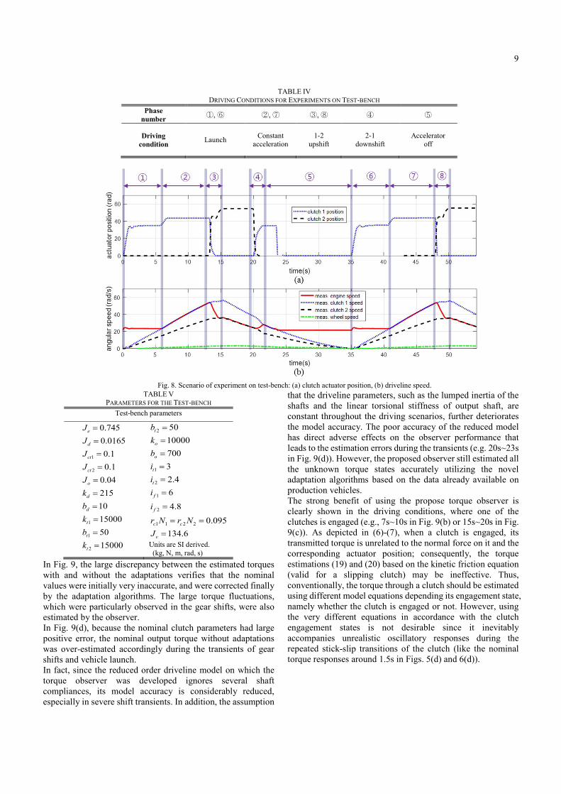
In Fig. 9, the large discrepancy between the estimated torques with and without the adaptations verifies that the nominal values were initially very inaccurate, and were corrected finally by the adaptation algorithms. The large torque fluctuations, which were particularly observed in the gear shifts, were also estimated by the observer. In Fig. 9(d), because the nominal clutch parameters had large positive error, the nominal output torque without adaptations was over-estimated accordingly during the transients of gear shifts and vehicle launch. In fact, since the reduced order driveline model on which the torque observer was developed ignores several shaft compliances, its model accuracy is considerably reduced, especially in severe shift transients. In addition, the assumption
that the driveline parameters, such as the lumped inertia of the shafts and the linear torsional stiffness of output shaft, are constant throughout the driving scenarios, further deteriorates the model accuracy. The poor accuracy of the reduced model has direct adverse effects on the observer performance that leads to the estimation errors during the transients (e.g. 20s~23s in Fig. 9(d)). However, the proposed observer still estimated all the unknown torque states accurately utilizing the novel adaptation algorithms based on the data already available on production vehicles. The strong benefit of using the propose torque observer is clearly shown in the driving conditions, where one of the clutches is engaged (e.g., 7s~10s in Fig. 9(b) or 15s~20s in Fig. 9(c)). As depicted in (6)-(7), when a clutch is engaged, its transmitted torque is unrelated to the normal force on it and the corresponding actuator position; consequently, the torque estimations (19) and (20) based on the kinetic friction equation (valid for a slipping clutch) may be ineffective. Thus, conventionally, the torque through a clutch should be estimated using different model equations depending its engagement state, namely whether the clutch is engaged or not. However, using the very different equations in accordance with the clutch engagement states is not desirable since it inevitably accompanies unrealistic oscillatory responses during the repeated stick-slip transitions of the clutch (like the nominal torque responses around 1.5s in Figs. 5(d) and 6(d)).
TABLE IV DRIVING CONDITIONS FOR EXPERIMENTS ON TEST-BENCH
Phase number ①, ⑥ ②, ⑦ ③, ⑧ ④ ⑤
Driving condition Launch Constant
acceleration 1-2
upshift 2-1
downshift Accelerator
off
Fig. 8. Scenario of experiment on test-bench: (a) clutch actuator position, (b) driveline speed.

10
On the other hand, the developed observer has the ability to self-adapt to continuously varying the parameters 1ct , 2ct to ensure accurate estimation of the torque, regardless of the clutch states. In fact, this feature of the observer is in line with its parameter convergence, irrelevant of the PE condition, described in Section III.D. In other words, although the adaptation law for each clutch torque is designed solely using the clutch friction model of slipping, it works for all the clutch states without its any structural change as a result of the novel structure of the torque observer.
C. Experiments on a Real Vehicle In the previous sub-sections, it was well observed from the results of the simulations and the experiment on the test-bench that each sub-estimator or adaptation law plays a crucial role in estimating the driveline torque states accurately. In order to further evaluate the application potential of the observer in production vehicles, experiments on a ground vehicle with the
dry-type DCT hardware were also conducted. Compared to the indoor test-bench, a vehicle is much more exposed to unexpected disturbances, and the vehicle load torque is varied unpredictably. Here, only one torque transducer was attached to the output shaft of the test vehicle, so the torque observer performance was quantitatively evaluated by comparing the measured output shaft torque with the estimated one. The vehicle test scenario that covers the launch phase and a clutch-to-clutch shift from 1st to 2nd gear is described in Fig. 10. Note that the position of the accelerator pedal actuated by the driver is also plotted in Fig. 10(a). In the test, the nominal engine torque from the ECU was directly used as the actual one. The corresponding test results are exhibited in Fig. 11. Note that the target clutch torque values based on the predefined maps with nominal parameters (denoted as “map-based”) were also presented in the results for comparison.
Fig. 9. Torque estimation by experiments on test-bench: (a) engine torque, (b) clutch 1 torque, (c) clutch 2 torque, (d) output shaft torque, (e) vehicle load torque

11
(a)
(b)
Fig. 10. Scenario of experiment on vehicle: (a) accelerator pedal/clutch actuator position, (b) driveline speed. The adaptation law for engine torque was activated right after the dis-engagement of the off-going clutch (clutch 1) during the shift (Fig. 11(a)), and the load torque adaptation was in effect throughout the test except for the gear shift (Fig. 11(e)). It is easily noticed from Fig. 11 that the individual adaptation laws corrected each torque variable, and the output shaft torque estimated by the final torque observer is very close to the measured one throughout the test (Fig. 11(d)). On the other hand, the output shaft torque estimated by the map-based clutch torques accompanied considerable errors. Consequently, the experimental results verified not only the effectiveness of the proposed torque observer, but also its application potential in production vehicles.
VI. CONCLUSION In this paper, a torque estimation method using an adaptive observer was proposed for a vehicle with DCT drivelines. The torque observer is able to estimate the transmitted torque of two clutches and the output shaft in the driveline, which is important for accurate powertrain controls. The advantages of the proposed torque estimation method are summarized as follows: (1) The observer has a function to correct the nominal engine torque from the ECU as well as the calculated vehicle load torque. (2) The observer only uses the driveline dynamics, so its performance is insensitive to the type and dynamics of clutch actuators. (3) The observer is based on a simplified driveline model, but it shows superior estimation performance with a few tuning parameters. (4) The observer works in all general driving conditions including gear shifts and vehicle launch without any change of its structure or parametric values. The estimation performance of the observer, including its robustness to parametric uncertainties, were well demonstrated through both simulations and experiments conducted under various driving scenarios.
(a)
(b)
(c)
(d)
(e)
Fig. 11. Torque estimation by experiment on vehicle: (a) engine torque, (b) clutch 1 torque, (c) clutch 2 torque, (d) output shaft torque, (e) vehicle load torque
ACKNOWLEDGMENT This work was supported in part by the Ministry of Science
and ICT (MSIT), Korea, under the Information Technology Research Center (ITRC) support program (grant IITP-2017-2012-0-00628) supervised by the Institute for Information & Communications Technology Promotion (IITP), the BK21 plus program, and the National Research Foundation of Korea (NRF) grant funded by the Korean government (MSIT) (grant 2017R1A2B4004116).
0 1 2 3 4 5 6 7 8time(s)
0
100
200
300
400
engi
ne to
rque
(Nm
)
nominal (from ECU)corrected w/ adaptation
clut
ch 1
torq
ue (N
m)
0 1 2 3 4 5 6 7 8
time(s)
0
200
400
600obtained by using (30)nominal (w/o adaptation)estimated w/ adaptation

12
REFERENCES [1] Y. Zhang, X. Chen, X. Zhang, W. Tobler, and H. Jiang, "Dynamic
modeling of a dual-clutch automated lay-shaft transmission," in ASME 2003 International Design Engineering Technical Conferences and Computers and Information in Engineering Conference, 2003, pp. 703-708.
[2] E. Galvagno, M. Velardocchia, and A. Vigliani, "Dynamic and kinematic model of a dual clutch transmission," Mechanism and Machine Theory, vol. 46, pp. 794-805, 2011.
[3] H. R. Lee, C. S. Kim, and T. C. Kim, "Double clutch transmission for a hybrid electric vehicle and method for operating the same," ed: US Patent Application, 2009.
[4] P. D. Walker and N. Zhang, "Active damping of transient vibration in dual clutch transmission equipped powertrains: A comparison of conventional and hybrid electric vehicles," Mechanism and Machine Theory, vol. 77, pp. 1-12, 2014.
[5] Z. Sun and K. Hebbale, "Challenges and opportunities in automotive transmission control," in American Control Conference, 2005. Proceedings of the 2005, 2005, pp. 3284-3289.
[6] M. Hoic, Z. Herold, N. Kranjcevic, J. Deur, and V. Ivanovic, "Experimental characterization and modeling of dry dual clutch thermal expansion effects," SAE International Journal of Passenger Cars-Mechanical Systems, vol. 6, pp. 775-785, 2013.
[7] A. Myklebust and L. Eriksson, "Modeling, observability, and estimation of thermal effects and aging on transmitted torque in a heavy duty truck with a dry clutch," IEEE/ASME transactions on mechatronics, vol. 20, pp. 61-72, 2015.
[8] M. Goetz, M. Levesley, and D. Crolla, "Dynamics and control of gearshifts on twin-clutch transmissions," Proceedings of the institution of mechanical engineers, Part D: Journal of Automobile Engineering, vol. 219, pp. 951-963, 2005.
[9] M. Kulkarni, T. Shim, and Y. Zhang, "Shift dynamics and control of dual-clutch transmissions," Mechanism and Machine Theory, vol. 42, pp. 168-182, 2007.
[10] P. D. Walker, N. Zhang, and R. Tamba, "Control of gear shifts in dual clutch transmission powertrains," Mechanical Systems and Signal Processing, vol. 25, pp. 1923-1936, 2011.
[11] K. van Berkel, T. Hofman, A. Serrarens, and M. Steinbuch, "Fast and smooth clutch engagement control for dual-clutch transmissions," Control Engineering Practice, vol. 22, pp. 57-68, 2014.
[12] Y. Liu, D. Qin, H. Jiang, and Y. Zhang, "Shift control strategy and experimental validation for dry dual clutch transmissions," Mechanism and Machine Theory, vol. 75, pp. 41-53, 2014.
[13] S. Kim, J. Oh, and S. Choi, "Gear shift control of a dual-clutch transmission using optimal control allocation," Mechanism and Machine Theory, vol. 113, pp. 109-125, 2017.
[14] B. Gao, H. Chen, Y. Ma, and K. Sanada, "Design of nonlinear shaft torque observer for trucks with Automated Manual Transmission," Mechatronics, vol. 21, pp. 1034-1042, 2011.
[15] J. Kim and S. B. Choi, "Control of dry clutch engagement for vehicle launches via a shaft torque observer," in American Control Conference (ACC), 2010, 2010, pp. 676-681.
[16] K.-s. Yi, B.-K. Shin, and K.-I. Lee, "Estimation of turbine torque of automatic transmissions using nonlinear observers," Journal of dynamic systems, measurement, and control, vol. 122, pp. 276-283, 2000.
[17] J.-O. Hahn and K.-I. Lee, "Nonlinear robust control of torque converter clutch slip system for passenger vehicles using advanced torque estimation algorithms," Vehicle System Dynamics, vol. 37, pp. 175-192, 2002.
[18] B. K. Shin, J. O. Hahn, and K. I. Lee, "Development of shift control algorithm using estimated turbine torque," SAE Technical Paper 0148-7191, 2000.
[19] R. A. Masmoudi and J. K. Hedrick, "Estimation of Vehicle Shaft Torque Using Nonlinear Observers," Journal of dynamic systems, measurement, and control, vol. 114, pp. 394-400, 1992.
[20] S. Watechagit and K. Srinivasan, "Modeling and simulation of a shift hydraulic system for a stepped automatic transmission," SAE Technical Paper 0148-7191, 2003.
[21] M. Ibamoto, H. Kuroiwa, T. Minowa, K. Sato, and T. Tsuchiya, "Development of smooth shift control system with output torque estimation," SAE Technical Paper 0148-7191, 1995.
[22] Z.-G. Zhao, J.-L. Jiang, Z.-P. Yu, and T. Zhang, "Starting sliding mode variable structure that coordinates the control and real-time optimization of dry dual clutch transmissions," International Journal of Automotive Technology, vol. 14, pp. 875-888, 2013.
[23] M. Wu, J. Zhang, T. Lu, and C. Ni, "Research on optimal control for dry dual-clutch engagement during launch," Proceedings of the Institution of Mechanical Engineers, Part D: Journal of Automobile Engineering, vol. 224, pp. 749-763, 2010.
[24] V. Tran, J. Lauber, and M. Dambrine, "Sliding mode control of a dual clutch during launch," in The second international conference on engineering mechanics and automation (ICEMA2), 2012, pp. 16-17.
[25] Z. Zhao, X. Li, L. He, C. Wu, and J. K. Hedrick, "Estimation of Torques Transmitted by Twin-clutch of Dry Dual Clutch Transmission during Vehicle’s Launching Process," IEEE Transactions on Vehicular Technology, 2016.
[26] Z. Zhao, L. He, Y. Yang, C. Wu, X. Li, and J. K. Hedrick, "Estimation of torque transmitted by clutch during shifting process for dry dual clutch transmission," Mechanical Systems and Signal Processing, vol. 75, pp. 413-433, 2016.
[27] H. Hao, T. Lu, and J. Zhang, "Estimation of transmitted torques in dual-clutch transmission systems," Insight-Non-Destructive Testing and Condition Monitoring, vol. 57, pp. 464-471, 2015.
[28] R. Losero, J. Lauber, T.-M. Guerra, and P. Maurel, "Dual clutch torque estimation Based on an angular discrete domain Takagi-Sugeno switched observer," in Fuzzy Systems (FUZZ-IEEE), 2016 IEEE International Conference on, 2016, pp. 2357-2363.
[29] J. J. Oh, S. B. Choi, and J. Kim, "Driveline modeling and estimation of individual clutch torque during gear shifts for dual clutch transmission," Mechatronics, vol. 24, pp. 449-463, 2014.
[30] J. J. Oh and S. B. Choi, "Real-time estimation of transmitted torque on each clutch for ground vehicles with dual clutch transmission," Mechatronics, IEEE/ASME Transactions on, vol. 20, pp. 24-36, 2015.
[31] P. Azzoni, D. Moro, F. Ponti, and G. Rizzoni, "Engine and load torque estimation with application to electronic throttle control," SAE technical paper 0148-7191, 1998.
[32] S. Kim, H. Jin, and S. B. Choi, "Exhaust Pressure Estimation for Diesel Engines Equipped With Dual-Loop EGR and VGT," IEEE Transactions on Control Systems Technology, DOI: 10.1109/TCST.2017.2665541, 2017.
[33] A. Crowther, N. Zhang, D. Liu, and J. Jeyakumaran, "Analysis and simulation of clutch engagement judder and stick-slip in automotive powertrain systems," Proceedings of the Institution of Mechanical Engineers, Part D: Journal of Automobile Engineering, vol. 218, pp. 1427-1446, 2004.
[34] M. Pettersson and L. Nielsen, "Gear shifting by engine control," IEEE Transactions on Control Systems Technology, vol. 8, pp. 495-507, 2000.
[35] D. Kim, H. Peng, S. Bai, and J. M. Maguire, "Control of integrated powertrain with electronic throttle and automatic transmission," IEEE Transactions on Control Systems Technology, vol. 15, pp. 474-482, 2007.
[36] F. Vasca, L. Iannelli, A. Senatore, and G. Reale, "Torque transmissibility assessment for automotive dry-clutch engagement," Mechatronics, IEEE/ASME Transactions on, vol. 16, pp. 564-573, 2011.
[37] S. Kim, S. B. Choi, and S. Kim, "Design of a highly efficient friction clutch apparatus for vehicle applications using a self-energizing mechanism," Proceedings of the Institution of Mechanical Engineers, Part D: Journal of Automobile Engineering, vol. 231, pp. 872-882, 2017.
[38] P. A. Ioannou and J. Sun, Robust adaptive control: Courier Corporation, 2012.
[39] G. Marafioti, R. R. Bitmead, and M. Hovd, "Persistently exciting model predictive control," International Journal of Adaptive Control and Signal Processing, vol. 28, pp. 536-552, 2014.
13
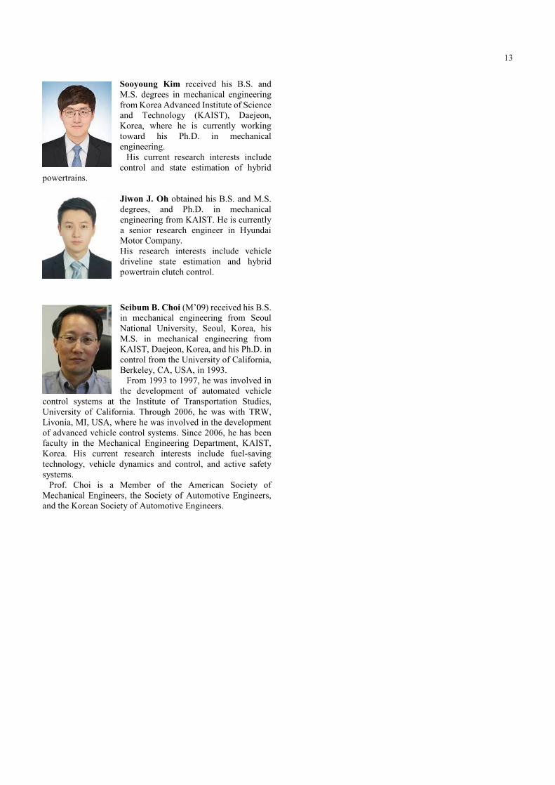
Sooyoung Kim received his B.S. and M.S. degrees in mechanical engineering from Korea Advanced Institute of Science and Technology (KAIST), Daejeon, Korea, where he is currently working toward his Ph.D. in mechanical engineering.
His current research interests include control and state estimation of hybrid
powertrains.
Jiwon J. Oh obtained his B.S. and M.S. degrees, and Ph.D. in mechanical engineering from KAIST. He is currently a senior research engineer in Hyundai Motor Company. His research interests include vehicle driveline state estimation and hybrid powertrain clutch control.
Seibum B. Choi (M’09) received his B.S. in mechanical engineering from Seoul National University, Seoul, Korea, his M.S. in mechanical engineering from KAIST, Daejeon, Korea, and his Ph.D. in control from the University of California, Berkeley, CA, USA, in 1993.
From 1993 to 1997, he was involved in the development of automated vehicle
control systems at the Institute of Transportation Studies, University of California. Through 2006, he was with TRW, Livonia, MI, USA, where he was involved in the development of advanced vehicle control systems. Since 2006, he has been faculty in the Mechanical Engineering Department, KAIST, Korea. His current research interests include fuel-saving technology, vehicle dynamics and control, and active safety systems.
Prof. Choi is a Member of the American Society of Mechanical Engineers, the Society of Automotive Engineers, and the Korean Society of Automotive Engineers.