Driveline and Wheel Components
9
After studying this chapter, you will be able to: � Identify types of drive axles and drive shafts. � Explain the design and construction of constant velocity flexible joints. � Explain the design and construction of cross-and-roller flexible joints. � Explain the purpose of antifriction bearings. � Identify types of wheel bearings. � Match axle types to bearing types. � Identify types of hubs and axle flanges. � Identify types of wheel rims. � Explain rim size specifications. � Identify tire designs. � Explain tire ratings. � Identify wheel fastener designs. 251 Chapter 12 Driveline and Wheel Components Ball bearings Straight roller bearings Tapered roller bearings Wheel hub Axle flange Wheel rims Radial tires Bias tires Tire ratings Section width Aspect ratio Load index Speed rating Uniform tire quality grading system Temperature resistance rating Traction rating Tread wear rating Wheel studs Lug nuts Tire pressure monitoring systems Independent drive axles CV axles Transfer shaft Drive shaft Yokes Slip yoke Constant velocity joints Universal joint Cross-and-roller joints Antifriction bearings Technical Terms This sample chapter is for review purposes only. Copyright © The Goodheart-Willcox Co., Inc. All rights reserved.
Transcript of Driveline and Wheel Components

After studying this chapter, you will be able to:� Identify types of drive axles and drive shafts.� Explain the design and construction of constant velocity flexible joints.� Explain the design and construction of cross-and-roller flexible joints.� Explain the purpose of antifriction bearings.� Identify types of wheel bearings.� Match axle types to bearing types.� Identify types of hubs and axle flanges.� Identify types of wheel rims.� Explain rim size specifications.� Identify tire designs.� Explain tire ratings.� Identify wheel fastener designs.
251
Chapter 12
Driveline andWheel
Components
Ball bearings
Straight roller bearings
Tapered roller bearings
Wheel hub
Axle flange
Wheel rims
Radial tires
Bias tires
Tire ratings
Section width
Aspect ratio
Load index
Speed rating
Uniform tire quality grading system
Temperature resistance rating
Traction rating
Tread wear rating
Wheel studs
Lug nuts
Tire pressure monitoring systems
Independent drive axles
CV axles
Transfer shaft
Drive shaft
Yokes
Slip yoke
Constant velocity joints
Universal joint
Cross-and-roller joints
Antifriction bearings
Technical Terms
This sample chapter is for review purposes only. Copyright © The Goodheart-Willcox Co., Inc. All rights reserved.

252 Auto Suspension and Steering
Introduction
This chapter covers the components related to vehicledrivelines and wheels. While some of these componentsare not directly related to the suspension and steering systems, they can cause vibration, noise, and other problems. These problems are often blamed on the suspension and steering components. Therefore, the sus-pension and steering technician must be familiar with thedesign and operation of drivelines and wheels so the realcause of problems can be determined.
Studying this chapter will illustrate how drivelines andwheel components fit into the overall vehicle design, andhow they can affect vehicle operation. This chapter will also discuss the design and materials used in the construction of these parts.
Driveline Components
Driveline components consist of the drive axles andshafts, flexible joints, and related parts. Drive axles can beroughly divided into solid and independent types. As ageneral rule, solid axles are used on rear-wheel drive vehicles and independent axles are used on front-wheeldrive vehicles. There are exceptions to this rule, especiallyon sport-utility vehicles and sports cars. The applicationand construction of both solid and independent drive axlesis discussed in the following section.
Several types of flexible joints are used on modernvehicles. The type of flexible joints used depends on thetype of axle. Design and use of flexible joints is also discussed below.
Independent Drive AxlesIndependent drive axles are usually called CV axles
because they use a type of flexible joint called a CV joint.All front-wheel drive vehicles, as well as a few rear-wheeldrive cars, use CV axles. CV axles are solid steel shafts thatconnect the transaxle output shafts to the wheels. A few CVaxles are constructed of hollow tubes to reduce weight androtating mass. There are always two CV axles on a front-wheel drive vehicle. Figure 12-1 shows a typical CV axleassembly. Note that there are four CV joints, two on eachaxle.
On a few vehicles, a transfer shaft, or intermediateshaft, is used between the transaxle and the CV shaft onone side of the vehicle, Figure 12-2. Use of a transfer shaftallows a support bearing to be placed midway between thetransaxle and the wheel. This reduces vibration and strainon the CV axle components. Transfer shafts are used onlarge cars and on cars with manual transaxles when thereis a large distance between the transaxle case and thewheels.
A few high-performance or sports cars use an independent rear axle, with exposed drive shafts containing CV joints. The construction of these shafts is thesame as those used on a front-wheel drive vehicle. Someolder independent rear axle shafts use U-joints instead ofCV joints.
Solid Drive AxlesOn most rear-wheel drive cars and trucks, the drive
axles are solid steel shafts. The shafts extend from the differential assembly gears to the wheel rims. Inside theaxle housing, external splines on the axle shafts mate withinternal splines on the differential gears. The shafts areenclosed in the rear axle housing and are supported bybearings.
Solid axle shafts are held in place by one of two methods. One design locks the shaft in place with an external retainer behind the brakes, while the other securesthe shaft with a C-lock located inside of the differentialassembly. Each design is shown in Figure 12-3.
Seals keep lubricant from leaking from the axle housing. Remember from Chapter 7 that the rear axle maybe called a Hotchkiss axle or a Salisbury axle, dependingon the type of rear springs used.
A few four-wheel drive vehicles have a solid front axlewith solid shafts. To allow the vehicle to turn, the ends ofthe shafts are attached to the wheel through flexible joints,Figure 12-4.
Drive plane
Cage
Inner race
Intermediateshaft
CV axle assembly
Support bearingCV
assembly
Figure 12-2. This front-wheel drive vehicle uses anintermediate shaft assembly. Study the layout.
Figure 12-1. Typical front-wheel drive axle assembly.
Chapter 12 Driveline and Wheel Components 253
Drive ShaftsAll rear-wheel drive vehicles use a drive shaft to
transfer engine power from the transmission to the rearaxle. Drive shafts are large hollow tubes that are carefullybalanced to reduce vibration. Flexible joints are installed ateach end through yokes, which are the mounting points forthe joints. Figure 12-5 is an illustration of a typical rear-wheel-drive drive shaft. Four-wheel drive vehicles have afront drive shaft that directs power from the four-wheeldrive transfer case to the front axle, Figure 12-6.
Bearingretainer
Bearingretainer nut
Bearing
Axleshaft
Rear axle housing
Brake backing plate
A
Seal
C-clip lock
Axleshaft
Sidegear
Ring gearB
Figure 12-3. A—A bearing retainer is used to hold this axle shaft in the axle housing. B—A C-clip lock placed in a grooved slot onthe end of this axle shaft holds the shaft in the housing. (General Motors & Dodge)
Steeringknuckle
Flexible joint
Tie rod
Tie rod jam nut
Connecting rodassembly
Steering stabilizer
Pitman arm
Figure 12-4. A four-wheel drive front axle assembly. (Chevrolet)
Some drive shafts are two-piece types, Figure 12-7.Two-piece drive shafts are usually used on large trucks,where a single drive shaft would be overstressed andbreak, and on some luxury cars, where any vibrationwould be objectionable. When a two-piece drive shaft isused, an extra flexible joint is necessary.
Slip YokeWhen the rear wheels move up and down, the
distance between the transmission and rear axle assembly
254 Auto Suspension and Steering
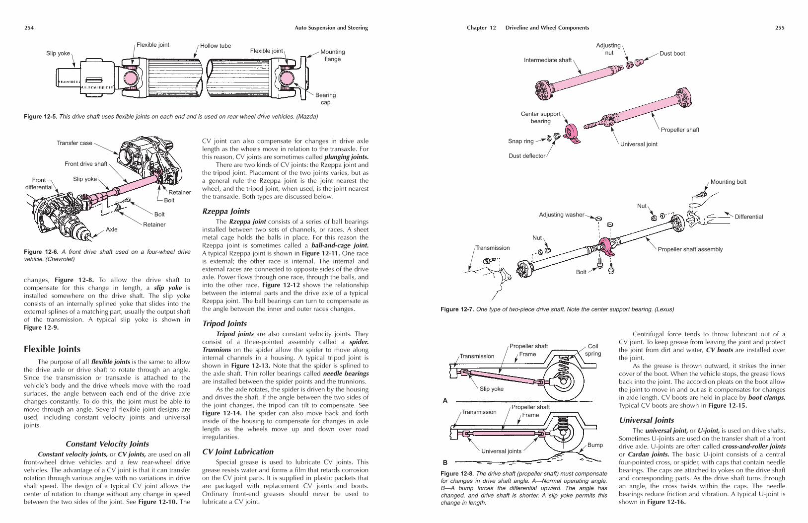
changes, Figure 12-8. To allow the drive shaft to compensate for this change in length, a slip yoke isinstalled somewhere on the drive shaft. The slip yoke consists of an internally splined yoke that slides into theexternal splines of a matching part, usually the output shaftof the transmission. A typical slip yoke is shown inFigure 12-9.
Flexible JointsThe purpose of all flexible joints is the same: to allow
the drive axle or drive shaft to rotate through an angle.Since the transmission or transaxle is attached to the vehicle’s body and the drive wheels move with the roadsurfaces, the angle between each end of the drive axlechanges constantly. To do this, the joint must be able tomove through an angle. Several flexible joint designs areused, including constant velocity joints and universaljoints.
Constant Velocity JointsConstant velocity joints, or CV joints, are used on all
front-wheel drive vehicles and a few rear-wheel drive vehicles. The advantage of a CV joint is that it can transferrotation through various angles with no variations in driveshaft speed. The design of a typical CV joint allows the center of rotation to change without any change in speedbetween the two sides of the joint. See Figure 12-10. The
CV joint can also compensate for changes in drive axlelength as the wheels move in relation to the transaxle. Forthis reason, CV joints are sometimes called plunging joints.
There are two kinds of CV joints: the Rzeppa joint andthe tripod joint. Placement of the two joints varies, but asa general rule the Rzeppa joint is the joint nearest thewheel, and the tripod joint, when used, is the joint nearestthe transaxle. Both types are discussed below.
Rzeppa JointsThe Rzeppa joint consists of a series of ball bearings
installed between two sets of channels, or races. A sheetmetal cage holds the balls in place. For this reason theRzeppa joint is sometimes called a ball-and-cage joint.A typical Rzeppa joint is shown in Figure 12-11. One raceis external; the other race is internal. The internal and external races are connected to opposite sides of the driveaxle. Power flows through one race, through the balls, andinto the other race. Figure 12-12 shows the relationshipbetween the internal parts and the drive axle of a typicalRzeppa joint. The ball bearings can turn to compensate asthe angle between the inner and outer races changes.
Tripod JointsTripod joints are also constant velocity joints. They
consist of a three-pointed assembly called a spider.Trunnions on the spider allow the spider to move alonginternal channels in a housing. A typical tripod joint isshown in Figure 12-13. Note that the spider is splined tothe axle shaft. Thin roller bearings called needle bearingsare installed between the spider points and the trunnions.
As the axle rotates, the spider is driven by the housingand drives the shaft. If the angle between the two sides ofthe joint changes, the tripod can tilt to compensate. SeeFigure 12-14. The spider can also move back and forthinside of the housing to compensate for changes in axlelength as the wheels move up and down over road irregularities.
CV Joint LubricationSpecial grease is used to lubricate CV joints. This
grease resists water and forms a film that retards corrosionon the CV joint parts. It is supplied in plastic packets thatare packaged with replacement CV joints and boots.Ordinary front-end greases should never be used to lubricate a CV joint.
Slip yokeFlexible joint Hollow tube
Flexible joint Mountingflange
Bearingcap
Figure 12-5. This drive shaft uses flexible joints on each end and is used on rear-wheel drive vehicles. (Mazda)
Frontdifferential
Slip yoke
Front drive shaft
Transfer case
RetainerBolt
Bolt
RetainerAxle
Figure 12-6. A front drive shaft used on a four-wheel drive vehicle. (Chevrolet)
Chapter 12 Driveline and Wheel Components 255
Centrifugal force tends to throw lubricant out of a CV joint. To keep grease from leaving the joint and protectthe joint from dirt and water, CV boots are installed overthe joint.
As the grease is thrown outward, it strikes the innercover of the boot. When the vehicle stops, the grease flowsback into the joint. The accordion pleats on the boot allowthe joint to move in and out as it compensates for changesin axle length. CV boots are held in place by boot clamps.Typical CV boots are shown in Figure 12-15.
Universal JointsThe universal joint, or U-joint, is used on drive shafts.
Sometimes U-joints are used on the transfer shaft of a frontdrive axle. U-joints are often called cross-and-roller jointsor Cardan joints. The basic U-joint consists of a centralfour-pointed cross, or spider, with caps that contain needlebearings. The caps are attached to yokes on the drive shaftand corresponding parts. As the drive shaft turns throughan angle, the cross twists within the caps. The needle bearings reduce friction and vibration. A typical U-joint isshown in Figure 12-16.
Intermediate shaftDust boot
Adjusting nut
Center supportbearing
Snap ring
Dust deflector
Universal joint
Propeller shaft
Transmission
Nut
Adjusting washer
Nut
Mounting bolt
Differential
Propeller shaft assembly
Bolt
Figure 12-7. One type of two-piece drive shaft. Note the center support bearing. (Lexus)
Transmission
Slip yoke
Propeller shaftFrame
Coilspring
Bump
Propeller shaftFrameTransmission
Universal joints
A
B
Figure 12-8. The drive shaft (propeller shaft) must compensatefor changes in drive shaft angle. A—Normal operating angle.B—A bump forces the differential upward. The angle haschanged, and drive shaft is shorter. A slip yoke permits thischange in length.

256 Auto Suspension and Steering
In operation, the cross of the U-joint transmits powerbetween the two yokes. Since the cross cannot move backand forth, the drive angle changes as the shaft rotatesthrough an angle. This causes the speed of the driven partof the drive shaft to vary. See Figure 12-17. The greater theangle, the more the vibration. For this reason, U-joints areused only where the angle between the yokes is relativelysmall.
Due to their design, cross-and-roller U-joints do notrequire a surrounding boot. Seals at the ends of the bearingcaps (where they enter the cross) keep lubricant in andwater and dirt out. Many U-joints are equipped with greasefittings. Conventional front suspension lubricant can beused to lubricate U-joints.
Wheel Components
The following sections cover the components relatedto a vehicle’s wheels. These components, which includethe wheel hubs, bearings, rims, tires, and fasteners, arefound on both driving and non-driving axles.
Propellershaft and
center bearing
Washer (2)
Bolt (2)68 N•m
(50 ft. lbs.)Clamp
Rear propellershaft
Slipyoke
Clamp
Boot
Propellershaft
Rear axle assembly
Screw andwasher assembly
Clamp
Propeller shaft
Slip yoke
Outputshaft
Transmission
Figure 12-9. A two-piece drive shaft showing the slip yoke. (Chrysler)
Wheel
Brake rotor
Hub
Ball bearing
Ball joint
Constant velocityjoint
Boot
Damper
Supportbearing
Differential
Intermediateshaft
Constant velocityjointStrut
Driveshaft
Figure 12-10. Cutaway of both inboard and outboard CV joints.(Honda)
Balls (6)
Inner race
Cage
Outer race
Elongatedopening
Figure 12-11. Exploded view of a Rzeppa (ball-type) constantvelocity joint. (AC Delco)
Chapter 12 Driveline and Wheel Components 257
Wheel BearingsThe wheel bearings form a low-friction connection
between the rotating wheels and the stationary vehicle. Allwheel bearings are antifriction bearings. Antifrictionbearings consist of three basic parts: the inner race, therolling element, and the outer race. See Figure 12-18. Therolling elements rotate between the two races, allowing theraces to move in relation to each other with a minimum offriction. The rolling action also draws lubricant betweenthe moving parts. The rolling elements and races are madeof heat-treated steel for maximum durability.
The clearances between the parts of an antifrictionbearing must be tight enough to prevent unwanted move-ment and vibration. However, the clearances must be looseenough to keep friction at a minimum, allow lubricant toenter between the moving parts, and compensate forexpansion as bearing temperature increases.
Other parts of antifriction bearings include the bearing cage, which keeps the individual rolling elementsseparated as they turn, and seals or shields, which keeplubricant in and dirt and water out.
Drive plane
Cage
Inner race
Drive Driven
Driven plane
Outer race
Bisecting plane
Figure 12-12. The balls in a Rzeppa joint operate in a bisectingplane between the angles of the axle shafts. As the jointrevolves, the position of the balls will change so they remain inthis bisecting plane. The position of the balls is controlled byelongated openings in the cage. (AC Delco)
Needle rollers
Trunnion
Housing
Shaft(axle)
C-clip
Spider
Balls
Grooves
Figure 12-13. Exploded view of a tripod constant velocity joint.(AC Delco)
Spider plane
Housing
DriveDriven
Spiderassembly
Figure 12-14. Tripod joint operation. The tripod joint uses threeballs on needle bearings to transmit torque between the spider(splined to the axle shaft) and the housing. As the joint revolves,the three balls will change their positions to stay in the sameplane as the spider. The balls can move in and out of the hous-ing to allow for length changes as the suspension travels up anddown. (AC Delco)
Bootclamp Boot Boot
Bootclamp
Boot clamp
Boot clamp
Drive shaft
Differential side Wheel side
Figure 12-15. A cutaway of a rear drive shaft showing the CV boots and clamps. (Lexus)
Needle bearing
Bearing cap
Seal
Cross
NeedlebearingSeal
Bearing cap
Retaining clip
Drive shaftyoke
Figure 12-16. A Cardan universal joint assembly. (Dodge)
258 Auto Suspension and Steering
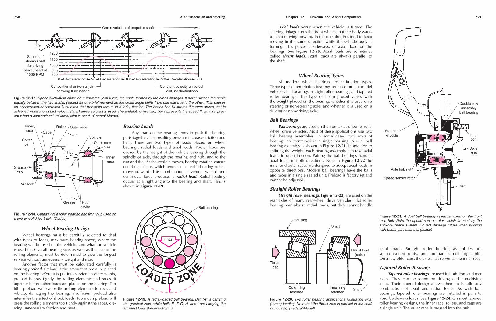
Wheel Bearing DesignWheel bearings must be carefully selected to deal
with types of loads, maximum bearing speed, where thebearing will be used on the vehicle, and what the vehicleis used for. Overall bearing size, as well as the size of therolling elements, must be determined to give the longestservice without unnecessary weight and size.
Another factor that must be calculated carefully isbearing preload. Preload is the amount of pressure placedon the bearing before it is put into service. In other words,preload is how tightly the rolling elements and races fittogether before other loads are placed on the bearing. Toolittle preload will cause the rolling elements to rock andvibrate, damaging the bearing. Insufficient preload alsointensifies the effect of shock loads. Too much preload willpress the rolling elements too tightly against the races, cre-ating unnecessary friction and heat.
Bearing LoadsAny load on the bearing tends to push the bearing
parts together. The resulting pressure increases friction andheat. There are two types of loads placed on wheel bearings: radial loads and axial loads. Radial loads arecaused by the weight of the vehicle passing through thespindle or axle, through the bearing and hub, and to therim and tire. As the vehicle moves, bearing rotation causescentrifugal force, which tends to make the bearing rollersmove outward. This combination of vehicle weight andcentrifugal force produces a radial load. Radial loadingoccurs at a right angle to the bearing and shaft. This isshown in Figure 12-19.
One revolution of propeller shaft
30°
1200
1100
1000
900800
0 90 180 270 360DecelerationDeceleration AccelerationAcceleration
Conventional universal jointshowing fluctuations
Constant velocity universaljoint, no fluctuations
Speeds ofdriven shaftfor driving
shaft speed of1000 RPM
Figure 12-17. Speed fluctuation chart. As a universal joint turns, the angle formed by the cross changes. It never divides the angleequally between the two shafts, (except for one brief moment as the cross angle shifts from one extreme to the other). This causesan acceleration-deceleration fluctuation that transmits torque in a jerky fashion. The dotted line illustrates the even speed that isachieved when a constant velocity (later) universal joint is used. The undulating (waving) line represents the speed fluctuation pres-ent when a conventional universal joint is used. (General Motors)
Roller
Cage
Innerrace
Greasecap
Nut lock
Grease Hubcavity
Innerrace
Seal
Spindle
Hub
Cotterpin
Outer race
Outer race
Figure 12-18. Cutaway of a roller bearing and front hub used ona two-wheel drive truck. (Dodge)
Ball bearing
AB
C
D
E
FG
H
I
J
K
L
LOAD
Figure 12-19. A radial-loaded ball bearing. Ball “A” is carryingthe greatest load, while balls E, F, G, H, and I are carrying thesmallest load. (Federal-Mogul)
Chapter 12 Driveline and Wheel Components 259
Axial loads occur when the vehicle is turned. Thesteering linkage turns the front wheels, but the body wantsto keep moving forward. In the rear, the tires tend to keepmoving in the same direction while the vehicle body isturning. This places a sideways, or axial, load on the bearings. See Figure 12-20. Axial loads are sometimescalled thrust loads. Axial loads are always parallel to the shaft.
axial loads. Straight roller bearing assemblies are self-contained units, and preload is not adjustable. On a few older cars, the axle shaft serves as the inner race.
Tapered Roller BearingsTapered roller bearings are used in both front and rear
axles. They can be found on driving and non-driving axles. Their tapered design allows them to handle any combination of axial and radial loads. As with ball bearings, tapered roller bearings are installed in pairs toabsorb sideways loads. See Figure 12-24. On most taperedroller bearing designs, the inner race, rollers, and cage area single unit. The outer race is pressed into the hub.
Wheel Bearing TypesAll modern wheel bearings are antifriction types.
Three types of antifriction bearings are used on late-modelvehicles: ball bearings, straight roller bearings, and taperedroller bearings. The type of bearing used varies with the weight placed on the bearing, whether it is used on asteering or non-steering axle, and whether it is used on adriving or non-driving axle.
Ball BearingsBall bearings are used on the front axles of some front-
wheel drive vehicles. Most of these applications use twoball bearing assemblies. In some cases, two rows of bearings are contained in a single housing. A dual ballbearing assembly is shown in Figure 12-21. In addition tosplitting the weight, each bearing assembly can take axialloads in one direction. Pairing the ball bearings handlesaxial loads in both directions. Note in Figure 12-22 theinner and outer races are designed to accept axial loads inopposite directions. Modern ball bearings have the ballsand races in a single sealed unit. Preload is factory set andcannot be adjusted.
Straight Roller BearingsStraight roller bearings, Figure 12-23, are used on the
rear axles of many rear-wheel drive vehicles. Flat rollerbearings can absorb radial loads, but they cannot handle
Thrustload
Housing
Shaft
Thrust load(axial)
Inner ringretained
Outer ringretained
Shaft
Figure 12-20. Two roller bearing applications illustrating axial(thrust) loading. Note that the thrust load is parallel to the shaftor housing. (Federal-Mogul)
Steeringknuckle
Axle hub nut
Speed sensor rotor
Axlehub
Lugbolt
Double-rowassembly
ball bearing
Disc
Figure 12-21. A dual ball bearing assembly used on the frontaxle hub. Note the speed sensor rotor, which is used by the anti-lock brake system. Do not damage rotors when workingwith bearings, hubs, etc. (Lexus)
262 Auto Suspension and Steering
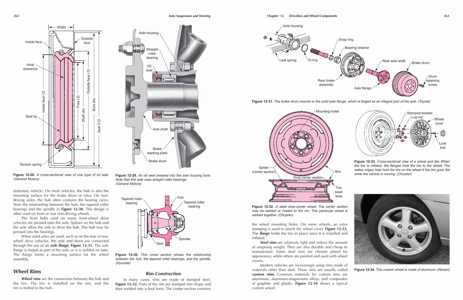
stationary vehicle. On most vehicles, the hub is also themounting surface for the brake drum or rotor. On non-driving axles, the hub often contains the bearing races.Note the relationship between the hub, the tapered rollerbearings and the spindle in Figure 12-30. This design isoften used on front or rear non-driving wheels.
The front hubs used on many front-wheel drive vehicles are pressed onto the axle. Splines on the hub andthe axle allow the axle to drive the hub. The hub may bepressed into the bearings.
When solid axles are used, such as on the rear of rear-wheel drive vehicles, the axle and drum are connectedthrough the use of an axle flange, Figure 12-31. The axleflange is forged as part of the axle, or it is welded on later.The flange forms a mounting surface for the wheel assembly.
Wheel RimsWheel rims are the connection between the hub and
the tire. The tire is installed on the rim, and the rim is bolted to the hub.
Rim ConstructionIn many cases, rims are made of stamped steel,
Figure 12-32. Parts of the rim are stamped into shape andthen welded into a final form. The center section contains
Free
I.D
.
Sha
ft di
a.
Out
side
face
I.D
.
Bor
e di
a.
Sea
l O.D
.
Insi
de fa
ce I.
D.
Width
OutsidefaceInside face
Tension spring
Seal lip
Axialclearance
Figure 12-28. A cross-sectional view of one type of oil seal.(General Motors)
Axle housing
Oilseal
Straightroller
bearing
Axle shaft
Brakebacking plate
Brake drum
Figure 12-29. An oil seal pressed into the axle housing bore.Note that this axle uses straight roller bearings.(General Motors)
HubTapered roller
bearing
SpindleSeal
Tapered rollerbearing
Figure 12-30. This cross section shows the relationshipbetween the hub, the tapered roller bearings, and the spindle.(Hyundai)
Chapter 12 Driveline and Wheel Components 263
the wheel mounting holes. On some wheels, an extrastamping is used to attach the wheel cover, Figure 12-33.The flange holds the tire in place once it is installed andinflated.
Steel rims are relatively light and reduce the amountof unsprung weight. They are also durable and cheap tomanufacture. Some steel rims are chrome plated forappearance, while others are painted and used with wheelcovers.
Modern vehicles are increasingly using rims made ofmaterials other than steel. These rims are usually calledcustom rims. Common materials for custom rims are aluminum, aluminum-magnesium alloys, and compositesof graphite and plastic. Figure 12-34 shows a typical custom wheel.
Axle housing
O-ring
Snap ring
Bearing retainer
Rear axle shaft Brake drum
Drumretaining
screwAxle flange
Rear brakeassembly
Leaf spring
Figure 12-31. The brake drum mounts to the solid axle flange, which is forged as an integral part of the axle. (Toyota)
Mounting holes
Rim
Drop center section
Tirebeadarea
Spider(center section)
Figure 12-32. A steel drop-center wheel. The center sectionmay be welded or riveted to the rim. This particular wheel iswelded together. (Chrysler)
Stamped bracketLug nut
Wheelcover
Lockbolt
Figure 12-33. Cross-sectional view of a wheel and tire. Whenthe tire is inflated, the flanges hold the tire to the wheel. Thesafety ridges help hold the tire on the wheel if the tire goes flatwhile the vehicle is moving. (Chrysler)
Figure 12-34. This custom wheel is made of aluminum. (Nissan)

264 Auto Suspension and Steering
The rim design used today is called the drop-centerwheel. The center section of the rim is lowered (ordropped), which allows the tire to be pulled to one side foreasier removal. Most rims have a small ridge behind thetire bead to hold the tire in place if a blowout occurs.These are called safety rims. See Figure 12-35.
Rim SizesThere are three measurements of rim sizes. The rim
diameter is most commonly used to describe rim size. Rimwidth is the size of the rim between the flanges. The flangeheight is how far the flange extends above the bead seat.Figure 12-36 illustrates the three measurements of a rim.These measurements apply to both steel and customwheels.
TiresTires perform two jobs: they cushion shocks and
provide traction. In their role as cushioning devices, theycan be considered part of the suspension system. As traction devices, they transmit engine power, as well asbraking and turning efforts, to the road.
Tire ConstructionThe external parts of the tire are the tread and the
sidewalls. Tread designs vary depending on the tire’s application. The sidewalls form the support for the treads.The tread and sidewalls are a blend of natural rubber anda synthetic rubber called neoprene.
The internal parts of the tires are composed of pliesand belts. The plies are layers of tire cord that form the general shape of the tire. Tire cords can be made of variousfabric materials, including nylon, rayon, polyester, aramid,Kevlar, or fiberglass. The belts are installed directly underthe tread and can be made of the same materials as theplies. Some belts are made of steel.
All modern tires are radial tires. In a radial tire, thecords in the plies cross the centerline of the tire at a rightangle to the tread. Older tires were called bias tires. In abias tire, the cords cross the centerline on a bias, or a slant.Almost all radial tires have one or two belts, which reducetread squirming, Figure 12-37.
Center section
Lug bolthole
Rim
Valve stem hole
Bolt circle
Flange height
Diameter
Rimwidth
Figure 12-36. The three most common rim measurements are diameter, rim width, and flange height. Another common measurement is wheel offset. Wheel offset is measured from the flange edge to the back of the center (spider) section. (Isuzu)
Flange
TireSafety ridges
Wheel
Drop center
Figure 12-35. A safety rim holds the tire in place in the event ofa blowout. (Chrysler)
Chapter 12 Driveline and Wheel Components 265
Tire RatingsModern tire ratings are designated by a system that
uses a series of numbers and letters. The ratings arestamped into or molded into the tire’s sidewall. An example of the rating that would be found on the sidewallof a typical tire is given in Figure 12-38.
The letter P designates the tire as a passenger car tire,Figure 12-39. Other letters used in this position are LT forlight truck, T for temporary (such as a space saver spare),and C for commercial (large trucks and construction vehi-cles). On tires that are suitable for both cars and trucks, thisletter is not used.
The number 205 is the section width, which is measured at the tire’s widest point. The section width is agood indication of tread width, and is generally consideredto be the tire size. The section width ranges from about 175on small tires to about 235 on large tires.
The number 70 is the aspect ratio, or the relationshipof the tire section width to its height, Figure 12-39. Lownumbers indicate a wide, low tire. The larger the number,the taller the tire.
The letter R indicates a radial tire. Other letters thatcould appear here are B and D for bias and belted tires.
The number 15 is the rim size in inches. The mostcommon rim sizes are 13, 14, and 15. A few vehicles have12-, 16-, or 17-inch rims, but these are uncommon.
The number 95 is the load index. The load index is anassigned number that corresponds to the amount of axleweight the tire can carry. In this case, a 95 load index indi-cates the tire can support 1521 lb. (690 kg). Load indexesusually range from 75–110.
The letter S is the speed rating. The speed rating indicates the maximum speed at which the tire should beoperated. Speed rating letters range from B, with a maxi-mum speed of 31 mph (50 km/h), to Z, with a maximumspeed of 149 mph (240 km/h). This number is also eliminated on some tires.
Tire Quality RatingsAs standardized by the United States Department of
Transportation (DOT), tires are graded according to theuniform tire quality grading system. The tire grades arestamped on the sidewall of the tire. This grading systemestablishes several quality grades, including the tempera-ture resistance rating, the traction rating, and the treadwear rating.
The temperature resistance rating rates the tire’sresistance to heat generation. Note that this grade is theresistance to generating heat, not its resistance to the heat
Stabilizerbelts
Radial cordbody plies
Figure 12-37. Typical construction of a radial tire. Sidewall pliesare parallel with each other and at right angles to tread center-line. Belts are under tread area. (Firestone)
Tiresidewall
Figure 12-38. Tire ratings are molded or stamped on the tire’ssidewall. All-season tires are generally marked with “M+S,”which means they are mud and snow rated. (Buick)
P 205 / 70 R 15 95S
Tire typeP–PassengerT–TemporaryLT–Light truck
Load index
Speed symbol
Sectionwidth
(millimeters)205215Etc.
Rimdiameter(inches)
141516
Aspectratio
(Section height)(Section width)
6070
Construction typeR–Radial
B–Bias–BeltedD–Diagonal (bias)
Section heightSectionwidth
Figure 12-39. Tire sidewall markings and their meanings.(Buick)
266 Auto Suspension and Steering
itself. The three grades are A, B, and C. A provides thegreatest resistance to heat; C provides the least.
The traction rating is also designated by the letters A,B, and C. A tire with an A rating has the best traction onwet surfaces, while a tire with a C rating has the least.
The tread wear rating is designated by a set of numbers. These numbers range from 100 to 500. A tirewith a rating of 200 should last about twice as long as a tirerated at 100.
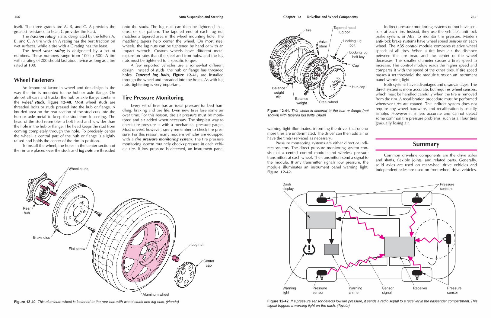
Wheel FastenersAn important factor in wheel and tire design is the
way the rim is mounted to the hub or axle flange. Onalmost all cars and trucks, the hub or axle flange containsthe wheel studs, Figure 12-40. Most wheel studs arethreaded bolts or studs pressed into the hub or flange. Aknurled area on the rear section of the stud cuts into thehub or axle metal to keep the stud from loosening. Thehead of the stud resembles a bolt head and is wider thanthe hole in the hub or flange. The head keeps the stud fromcoming completely through the hole. To precisely centerthe wheel, a central part of the hub or flange is slightlyraised and holds the center of the rim in position.
To install the wheel, the holes in the center section ofthe rim are placed over the studs and lug nuts are threaded
onto the studs. The lug nuts can then be tightened in across or star pattern. The tapered end of each lug nutmatches a tapered area in the wheel mounting hole. Thematching tapers help center the wheel. On most steelwheels, the lug nuts can be tightened by hand or with animpact wrench. Custom wheels have different metalexpansion rates than the steel and iron hubs, and the lugnuts must be tightened to a specific torque.
A few imported vehicles use a somewhat differentdesign. Instead of studs, the hub or flange has threadedholes. Tapered lug bolts, Figure 12-41, are installedthrough the wheel and threaded into the holes. As with lugnuts, tightening is very important.
Tire Pressure MonitoringEvery set of tires has an ideal pressure for best han-
dling, braking and tire life. Even new tires lose some airover time. For this reason, tire air pressure must be moni-tored and air added when necessary. The simplest way tocheck tire pressure is with a mechanical pressure gauge.Most drivers, however, rarely remember to check tire pres-sure. For this reason, many modern vehicles are equippedwith a tire pressure monitoring system. The tire pressuremonitoring system routinely checks pressure in each vehi-cle tire. If low pressure is detected, an instrument panel
Lug nut
Centercap
Aluminum wheel
Flat screw
Rearhub
Brake disc
Wheel studs
Figure 12-40. This aluminum wheel is fastened to the rear hub with wheel studs and lug nuts. (Honda)
Chapter 12 Driveline and Wheel Components 267
Indirect pressure monitoring systems do not have sen-sors at each tire. Instead, they use the vehicle’s anti-lockbrake system, or ABS, to monitor tire pressure. Modernanti-lock brake systems have wheel speed sensors on eachwheel. The ABS control module compares relative wheelspeeds of all tires. When a tire loses air, the distancebetween the tire tread and the center of the wheeldecreases. This smaller diameter causes a tire’s speed toincrease. The control module reads the higher speed andcompares it with the speed of the other tires. If tire speedpasses a set threshold, the module turns on an instrumentpanel warning light.
Both systems have advantages and disadvantages. Thedirect system is more accurate, but requires wheel sensors,which must be handled carefully when the tire is removedfrom the rim. A recalibration procedure must be performedwhenever tires are rotated. The indirect system does notrequire any wheel hardware, and recalibration is usuallysimpler. However it is less accurate and cannot detectsome common tire pressure problems, such as all four tiresgradually losing air.
Summary
Common driveline components are the drive axlesand shafts, flexible joints, and related parts. Generally,solid axles are used on rear-wheel drive vehicles and independent axles are used on front-wheel drive vehicles.
Tire
Valvestem
Tapered headlug bolt
Steel wheel
Locking lugbolt
Locking lugbolt key
Cap
Hub cap
Balanceweight
Balanceweight
clip
Figure 12-41. This wheel is secured to the hub or flange (notshown) with tapered lug bolts. (Audi)
warning light illuminates, informing the driver that one ormore tires are underinflated. The driver can then add air orhave the tire(s) serviced as necessary.
Pressure monitoring systems are either direct or indi-rect systems. The direct pressure monitoring system con-sists of a central control module and wireless pressuretransmitters at each wheel. The transmitters send a signal tothe module. If any transmitter signals low pressure, themodule illuminates an instrument panel warning light,Figure 12-42.
Figure 12-42. If a pressure sensor detects low tire pressure, it sends a radio signal to a receiver in the passenger compartment. Thissignal triggers a warning light on the dash. (Toyota)
Dashdisplay
Pressuresensors
Warninglight
Pressuresensor
Pressuresensor
Warningchime
Sensorsignal
Receiver

Chapter 12 Driveline and Wheel Components 269
13. All wheel bearings have a series of _____ elementsbetween inner and outer _____.
14. A tapered roller bearing always has a threaded nut,which is used to adjust _____.
15. What lubricates the wheel bearings on a solid rearaxle?
16. Tires perform two jobs. What are they?
17. Nylon, rayon, polyester, and fiberglass are used tomake tire _____.
18. The letters LT at the front of a tire rating indicate thatthe tire is intended for use on a(n) _____ _____.
19. The number 14 at the end of a tire rating indicatesthe _____ size.
20. Wheel studs are usually _____ into the hub or axleflange.
ASE-Type Questions—Chapter 12
1. Technician A says that front-wheel drive vehiclesalways have four CV joints on the front axles.Technician B says that front-wheel drive vehiclesalways have transfer shafts. Who is right?(A) A only.(B) B only.(C) Both A and B.(D) Neither A nor B.
2. Why are some CV joints called plunging joints?(A) They allow the axle shaft to move parallel to the
vehicles centerline.(B) They allow the axle shaft to change length.(C) They prevent grease loss.(D) There is no reason.
3. Technician A says that CV boots keep CV jointgrease from flying out of the joint as it turns.Technician B says that CV joints can be lubricatedwith any kind of quality EP grease. Who is right?(A) A only.(B) B only.(C) Both A and B.(D) Neither A nor B.
4. Which of the following flexible joints is the mostlikely to be equipped with grease fittings?(A) Tripod CV joint.(B) Rzeppa CV joint.(C) Plunging CV joint.(D) Cross-and-roller U-joint.
5. All of the following statements about bearing preloadare true except:(A) preload is how tightly the rolling elements and
races fit together after all vehicle weight is placedon the bearing.
(B) too little preload will damage the bearingbecause of vibration.
(C) too little preload intensifies the effect of shockloads.
(D) too much preload will create unnecessary fric-tion and heat.
6. EP lubricant is a type of _____.(A) hypoid oil(B) gear oil(C) lithium grease(D) long fiber grease
7. Technician A says that the purpose of the garterspring is to hold the lip of a seal to the shaft.Technician B says that the purpose of the garterspring is to create an oil film between the shaft andlip. Who is right?(A) A only.(B) B only.(C) Both A and B.(D) Neither A nor B.
8. All of the following statements about tire construc-tion are true except:(A) the cords in radial tire plies cross the centerline
of the tire at a right angle to the tread.(B) belts are installed directly under the tire tread.(C) tire cords are made of a combination of natural
rubber and neoprene.(D) some belts are made of steel.
9. Which of the following is NOT a common rim size?(A) 12 inches.(B) 13 Inches.(C) 14 inches.(D) 15 inches.
10. The tapered areas of the lug nut and wheel mountingholes help to _____ the wheel rim and tire.(A) balance(B) center(C) cool(D) seal
268 Auto Suspension and Steering
Independent drive axles are usually called CV axles. CV axles are solid steel shafts or hollow tubes that connectthe transaxle output shafts to the wheels. There are alwaystwo CV axles on a front-wheel drive vehicle. Some front-wheel drive vehicles have a transfer shaft on one side. Afew high-performance or sports cars use an independentrear axle with CV joints. Some older independent rearaxles have U-joints.
On most cars and trucks with rear-wheel drive, thedrive axles are solid steel shafts that extend from the differential assembly to the wheel hubs. Some four-wheeldrive vehicles have a solid front axle. All front-engine, rear-wheel drive vehicles use a drive shaft between the transmission and rear axle. Some drive shafts are two piecetypes. Four-wheel drive vehicles also have a front drive shaft.
Several types of flexible joints are used on modernvehicles. The type of flexible joint used depends on thetype of axle being used. CV joints are used on all front-wheel drive vehicles and a few rear-wheel drives.They are able to transmit power through an angle withoutcausing variations in shaft speed. There are two kinds of CV joints, the Rzeppa joint and the tripod joint.
The Rzeppa joint consists of a set of ball bearingsinside of two sets of races. The ball bearings can movebetween the channels to compensate for changes in angle.Tripod joints consist of a three point spider and trunnionsthat rotate on roller bearings. The spider and trunnions areplaced in a housing. As the axle rotates, the trunnions andspider are driven by the housing and tilt to compensate forangle changes. CV joint boots keep lubricant in and dirtand water out.
The U-joint, or Cardan joint, is used with drive shafts.U-joints consist of a four-point cross and caps that turn onneedle bearings. The cross can twist as it rotates to compensate for shaft angle changes. U-joints are usedwhen the angle change between rotating parts is not too great.
Wheel bearings form a low-friction connectionbetween the wheels and the vehicle. All wheel bearingsare antifriction bearings consisting of three basic parts: theinner race, the rolling element, and the outer race. Thereare two kinds of bearing loads. Radial loads are caused bythe weight of the vehicle and by centrifugal force. Axialloads are sideways loads that occur when the vehicle is turned.
The three types of antifriction wheel bearings are theball bearing, the flat roller bearing, and the tapered rollerbearing. Ball bearings are found on the front axles of manyfront-wheel drive vehicles. The balls and races are in a single sealed unit. Straight roller bearings are often used onthe rear axles of rear-wheel drive vehicles. Tapered rollerbearings are used in front and rear axles and are alwaysinstalled in pairs to absorb sideways loads. Tapered rollerbearing preload is adjustable.
Most tapered wheel bearings are packed with wheelbearing grease, which must be periodically renewed. Someball bearings and straight roller wheel bearings are greased
for life. Oil splash from the rotating gears is often used as alubrication method on solid rear axles.
The two main classes of wheel bearing lubricants arewheel bearing greases and gear oils. Most wheel bearingsare lubricated by grease. Some solid rear axle wheel bearings are lubricated with gear oil. The wheel bearingson most modern vehicles call for EP lithium grease. Wheelbearings used in solid rear axles are sometimes lubricatedwith the gear oil used to lubricate other rear axle parts.Bearing seals keep the oil or grease in, and water out.
The wheel hubs and axle flanges are the mountingsurface for the wheel rims and tires. The hub may containthe bearing races. Front hubs used on front-wheel drivevehicles are often pressed onto the axle.
Wheel rims are the connection between the hub andthe tire. The rim design used today is called the drop-center wheel. Rims are made of stamped steel or variousalloys. Rim size determines what type of tire will be used,and is composed of diameter, width and flange height.
Tires have the job of cushioning road shocks and pro-viding traction. External parts of the tire are the tread andthe sidewalls. Internal parts are the plies and belts. Moderntires are radial tires. Older tires were called bias tires. Tireratings and quality grades are stamped on or molded intothe side of the tire.
The wheel rim is mounted to the hub or axle flangethrough wheel studs and lug nuts. A few vehicles usetapered bolts instead of lug nuts and studs.
Review Questions—Chapter 12
1. Why are front-wheel drive independent axles calledCV axles?
2. While most CV axles are _____ steel shafts, a few are_____ to reduce weight.
3. A four-wheel drive vehicle has two _____.
4. What is the purpose of a drive shaft slip yoke?
MatchingMatch the drive axle with the type of flexible joint.
5. Independent front axle. a. CV joint.
6. Independent rear axle. b. U-joint.
7. Solid rear axle. c. No flexible joint.
8. Rear-wheel drive shaft.
9. Front-wheel drive shaft, four-wheel drive.
10. A Rzeppa joint uses _____ between the races toallow angle changes.
11. A tripod CV joint uses three _____, which are sepa-rated from the spider by needle bearings.
12. All wheel bearings are known as what kind of bearings?