Drive One Wireless Follow Focus Test report - … · institute of testing and certification (india)...
55
REMARKS: This report is governed by, and incorporates by reference, the Condition of testing as posted at its date of issuance and is intended for your exclusive use. Any copying or replication of this report to or for any other person or entity, or use of our name or trademark, is permitted only with our prior written permission. This report sets forth solely our findings with respect to the test samples identified herein. It includes all of the test requested by you and the results thereof based upon the information that you provided us with. You have 10 calendar days from the date of issuance of this report to notify us of any material error or omission; provided, however, that such notice shall be written and shall specifically address the issue you wish to raise. A failure to raise such issue within the prescribed time shall constitute your unqualified acceptance of the completeness of this report, the tests conducted and the correctness of the report contents. Tests are destructive and non reversible, the submitted samples will not return to their original conditions. The client acknowledges that any remaining part of the sample will be discarded if not retreived in a period of 30 calendar days from the date of issuance of this report. ELECTRICAL LABORATORY- TEST REPORT Information Technology Equipment – Safety – Part 1: General requirements Test Report N°……………………..……… ITC/TEST/NN/1609/08 Date of issue………………………….……. Sample date in…………………….……… 27-09-2016 Date of performance……………........... 27-09-2016 to Applicant…………………………………… Mr. Mrityunjay Kumar Sharma Customer…………………………....……… Active Photo Service Pvt. Ltd Plot No. - 103, Industrial Area, Phase-1 Chandigarh (INDIA) Sample description…………………….. Drive one wireless follow focus Sample Condition…………………...….. OK Customer reference………………..….. N/A Trade mark / Manufacturer……..… Model / Type / Reference………...… WF645 Ratings……………………………..…..……. 8-15VDC, 2W Test method(s)……………….…….…….. BS EN 60950-1:2006+A2: 2013 Overall verdict Pass Fail Page 1 of 55
Transcript of Drive One Wireless Follow Focus Test report - … · institute of testing and certification (india)...
REMARKS: This report is governed by, and incorporates by reference, the Condition of testing as posted at its date of issuance and is intended for your exclusive use. Any copying or replication of this report to or for any other person or entity, or use of our name or trademark, is permitted only with our prior written permission. This report sets forth solely our findings with respect to the test samples identified herein. It includes all of the test requested by you and the results thereof based upon the information that you provided us with. You have 10 calendar days from the date of issuance of this report to notify us of any material error or omission; provided, however, that such notice shall be written and shall specifically address the issue you wish to raise. A failure to raise such issue within the prescribed time shall constitute your unqualified acceptance of the completeness of this report, the tests conducted and the correctness of the report contents. Tests are destructive and non reversible, the submitted samples will not return to their original conditions. The client acknowledges that any remaining part of the sample will be discarded if not retreived in a period of 30 calendar days from the date of issuance of this report.
ELECTRICAL LABORATORY- TEST REPORT Information Technology Equipment – Safety –
Part 1: General requirements
Test Report N°……………………..……… ITC/TEST/NN/1609/08
Date of issue………………………….…….
Sample date in…………………….……… 27-09-2016
Date of performance……………........... 27-09-2016 to
Applicant…………………………………… Mr. Mrityunjay Kumar Sharma
Customer…………………………....……… Active Photo Service Pvt. Ltd
Plot No. - 103, Industrial Area, Phase-1
Chandigarh (INDIA)
Sample description…………………….. Drive one wireless follow focus
Sample Condition…………………...….. OK
Customer reference………………..….. N/A
Trade mark / Manufacturer……..…
Model / Type / Reference………...… WF645
Ratings……………………………..…..……. 8-15VDC, 2W
Test method(s)……………….…….…….. BS EN 60950-1:2006+A2: 2013
Overall verdict Pass
Fail Page 1 of 55
INSTITUTE OF TESTING AND CERTIFICATION (INDIA) PVT. LTD.
Possible test case verdicts:
Test case does not apply to the test object ................................................................. N/A Test object meets the requirement ................................................................................ P (Pass) Test object does not meet the requirement ............................................................... F (Fail)
General remarks:
“ See enclosure ## ” refers to additional information related to this report in the annexes section
“ See table ## ” refers to a table appended to this report in the annexes section “ See figure ## ” refers to an image, picture or drawing appended to this report in the annexes
section
General product information: Pictures of Specimen received:
Drive one wireless follow focus Model No.: WF645
Testing Engineer Gurwinder Singh
Technical Manager Naveen Chopra

INSTITUTE OF TESTING AND CERTIFICATION (INDIA) PVT. LTD.
TEST REPORT No: ITC/TEST/NN/1609/08 Page 3 of 55
COPY OF MARKING PLATE

INSTITUTE OF TESTING AND CERTIFICATION (INDIA) PVT. LTD.
BS EN 60950-1
Clause no. Requirement – Test Results – Remarks Verdict
TEST REPORT No: ITC/TEST/NN/1609/08 Page 4 of 55
1.5 Components
1.5.1 GENERAL
Where safety is involved, components shall comply with the requirement of this standard.
P
1.5.2 Evaluation and testing of components In compliance P
1.5.3 Thermal controls No thermal controls N/A
1.5.4 Transformers No such transformer N/A
1.5.5 Interconnecting cables In compliance P
1.5.6 Capacitors bridging insulation N/A
1.5.7 Resistors bridging insulation N/A
1.5.8 Components in equipment for IT power distribution systems
Class III equipment. N/A
1.5.9 Surge suppressors Class III equipment. N/A
1.5.9.1 General N/A
1.5.9.2 Protection of VDRs N/A
1.5.9.3 Bridging of functional insulation by a VDR N/A
1.5.9.4 Bridging of supplementary, double or reinforced insulation by a VDR
N/A
1.6 Power interface
1.6.1 AC power distribution systems In built DC power system works on primary cells only
N/A
1.6.2 Input current
The steady state input current of the equipment shall not exceed the RATED CURRENT by more than 10 % under NORMAL LOAD.
P
1.6.3 Voltage limit of hand-held equipment
The rated voltage of HAND-HELD equipment shall not exceed 250 V.
SELV circuit P
1.6.4 Neutral conductor N/A
1.7 Markings and instructions
1.7.1 Power rating and Identification markings
1.7.1.1 Power rating markings
The power rating marking shall include the following:
- Rated voltage(s) rated voltage range(s), in volts Provided P
- Symbol for nature of supply, for d.c only Not Provided

INSTITUTE OF TESTING AND CERTIFICATION (INDIA) PVT. LTD.
BS EN 60950-1
Clause no. Requirement – Test Results – Remarks Verdict
TEST REPORT No: ITC/TEST/NN/1609/08 Page 5 of 55
- Rated current, in milli amperes or amperes Not Provided
1.7.1.2 Identification markings
Equipment shall be provided by the following identification markings:
-manufacturer's name or trade-mark or identification mark;
Provided P
-manufacturer's model identification or type reference; Provided P
- Symbol, for the identification of CLASS II equipment only, except where this is forbidden by 2.6.2.
Class III equipment. N/A
1.7.1.3 Use of graphical symbols
Graphical symbols placed on the equipment, whether required by this standard or not, shall be in accordance with IEC 60417 or ISO 3864-2 or ISO 7000,
P
Symbols placed on the equipment shall be explained in the user manual.
P
1.7.2 Safety instructions and marking
1.7.2.1 General
1.7.2.2 Disconnect devices
Where the disconnect device is not incorporated in the equipment (see 3.4.3) or where the plug on the power supply cord is intended to serve as the disconnect device.
Class III equipment. -
- for permanently connected equipment, a readily accessible disconnect device shall be incorporated external to the equipment;
Equipment does not connect to mains supply.
N/A
- for pluggable equipment, the socket-outlet shall be installed near the equipment and shall be easily accessible.
Equipment does not connect to mains supply.
N/A
1.7.2.3 Over current protective devices
Pluggable equipment type B or permanently connected equipment, the installation instructions shall specify the maximum rating of an over current protective device to be provided external to the equipment
Equipment does not connect to mains supply.
N/A
1.7.2.4 IT power distribution systems
lf the equipment has been designed or, when required, modified for connection to an lT power distribution system, the equipment installation instructions shall so state.
Operated on DC supply
N/A

INSTITUTE OF TESTING AND CERTIFICATION (INDIA) PVT. LTD.
BS EN 60950-1
Clause no. Requirement – Test Results – Remarks Verdict
TEST REPORT No: ITC/TEST/NN/1609/08 Page 6 of 55
1.7.2.5 Operator access with a tool
lf a tool is necessary to gain access to an operator access area, either all other compartments within that area containing a hazard shall be inaccessible to the operator by the use of the same tool,
N/A
An acceptable marking for an electric shock hazard is
(lSO 3864, No. 5036) N/A
1.7.2.6 Ozone
For equipment that may produce ozone, the installation and operating instructions shall refer to the need to take precautions to ensure that the concentration of ozone is limited to a safe value.
N/A
1.7.3 Short duty cycles
Equipment not intended for continuous operation shall be marked with its rated operating time and rated resetting time unless the operating time is limited by the construction.
N/A
1.7.4 Supply voltage adjustment
Equipment intended for connection to multiple rated voltages or frequencies, the method of adjustment shall be fully described in the servicing or installation instructions.
N/A
1.7.5 Power outlets on the equipment
lf any standard power supply outlet in the equipment is accessible to the operator, a marking shall be placed in the vicinity of the outlet to show the maximum load that is permitted to be connected to it.
N/A
1.7.6 Fuse identification
Marking shall be located adjacent to each fuse or fuse holder, or on the fuse holder, or in another location provided that it
N/A
1.7.7 Wiring terminals
1.7.7.1 Protective earthing and bonding terminals
A wiring terminal intended for connection of a protective earthing conductor shall be indicated by the symbol , IEC 60417- 5019
The equipment is class III.
N/A
1.7.7.2 Terminals for a,c. mains supply conductors
Permanently connected and equipment with ordinary non- detachable power supply cords:
-
- terminals intended exclusively for connection of the a.c mains supply neutral conductor, if any, shall be indicated by the capital letter N;
N/A

INSTITUTE OF TESTING AND CERTIFICATION (INDIA) PVT. LTD.
BS EN 60950-1
Clause no. Requirement – Test Results – Remarks Verdict
TEST REPORT No: ITC/TEST/NN/1609/08 Page 7 of 55
-
on three-phase equipment, if incorrect phase rotation could cause overheating or other hazard, terminals intended for connection of the a.c mains supply line conductors shall be marked in such a way that, in conjunction with any installation instructions, the sequence of phase rotation is unambiguous.
N/A
1.7.7.3 Terminals for d.c, mains supply conductors
Permanently connected equipment and equipment with ordinary non- detachable power supply cords, terminals intended exclusively for connection of a d.c mains supply shall be marked to indicate polarity.
works on primary cells only
N/A
1.7.8 Controls and indicators
1.7.8.1 identification, location and marking -
Markings and indications for switches and other controls shall be located either:
-
- on or adjacent to the switch or control, or P
- elsewhere, provided that it is obvious to which switch or control the marking applies.
P
1.7.8.2 Colours
safety is involved, colours of controls and indicators shall comply with IEC 60073.Where colours are used for functional controls or indicators, any colour, including red, is permitted provided that it is clear that safety is not involved,
LED’s provided for functional control only
N/A
1.7.8.3 Symbols
symbols are used on or near controls (for example, switches and push buttons) to indicate "ON" and "OFF"
conditions, they shall be the line for "ON" and circle for “OFF” (lEC 60417-5007 (DB:2002-10)
P
Use the symbols and to indicate the "OFF" and “ON’’ positions of any primary or secondary power switches, including isolating switches.
P
A 'STAND-BY' condition shall be indicated by the
symbol (IEC 60417-5009 (DB:2002-10). N/A
1.7.8.4 Markings using figures
lf figures are used for indicating different positions of any control, the "OFF" position shall be indicated by the figure 0 (zero) and higher figures shall be used to indicate greater output, input, etc.
N/A

INSTITUTE OF TESTING AND CERTIFICATION (INDIA) PVT. LTD.
BS EN 60950-1
Clause no. Requirement – Test Results – Remarks Verdict
TEST REPORT No: ITC/TEST/NN/1609/08 Page 8 of 55
1.7.9 lsolation of multiple power sources N/A
1.7.10 Thermostats and other regulating devices
Thermostats and similar regulating devices intended to be adjusted during installation or in normal use shall be provided with an indication for the direction of adjustment to increase or decrease the value of the characteristic being adjusted. Indication by the symbols + and – is permitted.
N/A
1.7.11 Durability
Marking required by this standard shall be durable and legible.
P
1.7.12 Removable parts
Marking required by this standard shall not be placed on removable parts that can be replaced in such a way that the marking would become misleading.
P
1.7.13 Replaceable batteries
18650 Rechargeable
Li-Ion Battery cell &
9V dry cell battery is
used
P
1.7.14 Equipment for restricted access locations
Equipment intended only for installation in a restricted access location, the installation instructions shall contain a statement to this effect.
N/A
2 Protection from hazards
2.1 Protection from electric shock and energy hazards P
2.1.1 Protection in operator access areas See below. P
2.1.1.1 Access to energized parts Equipment is class III.
N/A
2.1.1.2 Battery compartments No TNV circuits in the equipment.
N/A
2.1.1.3 Access to ELV wiring N/A
2.1.1.4 Access to hazardous voltage circuit wiring
The insulation of internal wiring at hazardous voltage is accessible to an operator, or is not routed and fixed to prevent it from touching unearthed accessible conductive parts, it shall meet the requirements of 3.1.4 for double insulation or reinforced insulation.
No hazardous voltage present.
N/A

INSTITUTE OF TESTING AND CERTIFICATION (INDIA) PVT. LTD.
BS EN 60950-1
Clause no. Requirement – Test Results – Remarks Verdict
TEST REPORT No: ITC/TEST/NN/1609/08 Page 9 of 55
2.1.1.5 Energy hazards
There shall be no risk of injury due to an energy hazard in an operator access area.
No energy hazard in operator access area.
P
2.1.1.6 Manual controls
Conductive shafts of operating shall not be connected to parts knobs, handles, levers and the like in operator access areas at hazardous voltages, to ELV circuits or to TNV circuits.
N/A
2.1.1.7 Discharge of capacitors in equipment
Equipment shall be so designed that, at an operator -accessible external point of disconnection of a mains supply, the risk of electric shock from stored charge on capacitors connected in the equipment is reduced.
N/A
2.1.1.8 Energy hazards - d.c mains supplies
Equipment shall be so designed that at an operator-accessible external point of disconnection of a DC mains supply
N/A
-
there is no hazardous energy level (for example, due to stored charge on a capacitor or a battery in the equipment, or to a redundant d.c mains supply for backup)
N/A
- the hazardous energy level is removed within 2 s of the disconnection.
N/A
2.1.1.9 Audio amplifiers in information technology equipment
No audio amplifier N/A
2.1.2 Protection in service access areas
The requirements of 2.1.1.7 apply to all types of equipment and for permanently connected equipment, the time constant limit is 10 s. ln addition, the requirements of 2.1.1.8apply.
N/A
2.1.3 Protection in restricted access locations
Equipment to be installed in a restricted access locations, the requirements for operator access area apply.
N/A
2.2 SELV circuits
2.2.1 General requirements
SELV circuits shall exhibit voltages that are safe to touch both under normal operating conditions and after a single fault (see 1.4.14). lf no external load is applied to the SELV current (open circuit), the voltage limits of 2.2.2 and 2.2.3 shall not be exceeded.
P
INSTITUTE OF TESTING AND CERTIFICATION (INDIA) PVT. LTD.
BS EN 60950-1
Clause no. Requirement – Test Results – Remarks Verdict
TEST REPORT No: ITC/TEST/NN/1609/08 Page 10 of 55
2.2.2 Voltages under normal conditions
a single SELV circuits or in interconnected SELV circuits, the voltage between any two conductors of the SELV circuit or circuits, and between any one such conductor and earth (see 1.4.9), shall not exceed 42,4 V peak, or 60 V d.c., under normal operating conditions.
P
2.2.3 Voltages under fault conditions
the event of a single fault (see1.4.14), the voltages between any two conductors of the SELV circuit or circuits and between any one such conductor and earth (see 1.4.9) shall not exceed 42,4 V peak, or 60 V d.c.
P
2.2.4 Connection of SELV circuits to other circuits
An SELV circuits is permitted to be connected to other circuits provided that, when the SELV circuit is so connected, all of the following conditions are met:
-
- except as permitted by 1.5.7 and 2.4.3, the SELV circuit is separated by basic insulation from any primary circuit (including the neutral)within the equipment;
P
- the SELV circuit meets the limits of 2.2.2 under normal operating conditions;
P
- except as specified in 2.3.2.1 b), the SELV circuit meets the limits of 2.2.3 in the event of a single fault (see 1.4.14) in the SELV circuits or in the secondary circuits to which the SELV circuit is connected.
P
2.3 TNV circuits
2.3.1 Limits
In a single TNV circuit or interconnected TNV circuit, the voltage between any two conductors of the TNV circuit or circuit and between any one such conductor and earth (see 1.4.9) shall comply with the following.
No TNV circuit in the equipment.
-
a) TNV-l circuits N/A
b) TNV-2 circuits and TNV-3 circuits N/A
2.3.2 Separation of TNV circuits from other circuits and from accessible parts
N/A
2.3.2.1 General requirement N/A
2.3.2.2 Protection by basic insulation N/A
2.3.2.3 Protection by earthing N/A
2.3.2.4 Protection by other construction N/A
2.3.3 Separation from hazardous voltages
Except as permitted in 2-3.4, a TNV circuit shall be separated from circuits at hazardous voltage by one or more of the constructions specified in 2.9.4.
N/A

INSTITUTE OF TESTING AND CERTIFICATION (INDIA) PVT. LTD.
BS EN 60950-1
Clause no. Requirement – Test Results – Remarks Verdict
TEST REPORT No: ITC/TEST/NN/1609/08 Page 11 of 55
2.3.4 Connection of TNV circuits to other circuits
Except as permitted in 1.5.7, a TNV circuit is permitted to be connected to other circuits, provided that it is separated by basic insulation from any primary circuit (including the neutral) within the equipment.
N/A
2.3.5 Test for operating voltages generated externally N/A
2.4 Limited current circuits
2.4.1 General requirements
Limited current circuits shall be so designed that the limits specified in 2.4.2 are exceeded under normal operating conditions and in the event of a single failure within equipment (see 1.4.14 and 1.5.7).
N/A
2.4.2 Limit values
For frequencies not exceeding 1 kHz, the steady-state current drawn through a non-inductive resistor of 2 000 Ω ±10 % connected between any two parts of a limited current circuit.
N/A
2.4.3 Connection of limited current circuits to other circuits
Limited current circuits are permitted to be supplied from or connected to other circuits, provided that the following conditions are met:
-
- The Limited current circuit meets the limits of 2.4.2 under normal operating conditions;
N/A
-
The Limited current circuit continues to meet the Limits of 2.4.2 in the event of a single failure of any component or insulation in the Limited current circuit, or of any component or insulation in the other circuit to which it is connected.
N/A
2.5 Limited power sources
A limited power source shall comply with one of the following, a), b), c) or d):
P
a) the output is inherently limited in compliance with Table 2B;
N/A
b) a linear or non-linear impedance limits the output in compliance with Table 2B
N/A
c) a regulating network, or an integrated circuit (lC) current limiter, limits the output in compliance with Table 2B
P
d) an over current protective device is used and the output is limited in compliance with Table 2C
N/A

INSTITUTE OF TESTING AND CERTIFICATION (INDIA) PVT. LTD.
BS EN 60950-1
Clause no. Requirement – Test Results – Remarks Verdict
TEST REPORT No: ITC/TEST/NN/1609/08 Page 12 of 55
2.6 Provisions for earthing and bonding
2.6.1 Protective earthing Class III equipment. N/A
2.6.2 Functional earthing
If functional earthing of accessible conductive parts is necessary all of the following apply to the functional earthing circuit:
N/A
2.6.3 Protective earthing conductors and protective bonding conductors
2.6.3.1 General
Protective earthing conductors and Protective bonding conductors shall have sufficient current-carrying capacity.
N/A
2.6.3.2 Size of protective earthing conductors
Protective earthing conductors in power supply cords supplied with the equipment shall comply with the minimum conductor sizes in Table 3B (see 3.2.5).
N/A
2.6.3.3 Size of protective bonding conductors
Protective bonding conductors shall comply with one of the following:
-
- the minimum conductor sizes in Table 3B (see 3.2.5); N/A
- the requirements of 2.6.3.4 and also, if the Protective current ratting more than.16 A, with the minimum conductor sizes in Table 2D
N/A
- for components only, be not smaller than the conductors supplying component.
N/A
2.6.3.4 Resistance of earthing conductors and their terminations
Earthing conductors and their terminations shall not have excessive resistance
N/A
2.6.3.5 Colour of insulation
The insulation of the protective earthing conductor in a power supply cord supplied with the equipment shall be green-and-yellow.
N/A
2.6.4 Terminals
2.6.4.1 General
2.6.4.2 Protective earthing and bonding terminals
Equipment required to have protective earthing shall have a main protective earthing terminal.
N/A

INSTITUTE OF TESTING AND CERTIFICATION (INDIA) PVT. LTD.
BS EN 60950-1
Clause no. Requirement – Test Results – Remarks Verdict
TEST REPORT No: ITC/TEST/NN/1609/08 Page 13 of 55
2.6.4.3 Separation of the protective earthing conductor from protective bonding conductors
Separate wiring terminals, which may be on the same busbar, shall be provided, one for the protective earthing conductor
N/A
2.6.5 lntegrity of protective earthing
2.6.5.1 lnterconnection of equipment
A system of interconnected equipment, the protective earthing connection shall be ensured for all equipment requiring a protective earthing connection, regardless of the arrangement of equipment in the system.
N/A
2.6.5.2 Components in protective earthing conductors and protective bonding conductors
Protective earthing conductors and protective bonding conductors shall not contain switches or over current protective devices.
N/A
2.6.5.3 Disconnection of protective earth
Protective earthing connections shall be such that disconnection of a protective earth at one point in a unit or a system does not break the protective earthing connection to other parts or units in a system, unless the relevant hazard is removed at the same time.
.
N/A
2.6.5.4 Parts that can be removed by an operator
Protective earthing connections shall make earlier and break later than the supply connections in each of the following:
-
- the connector of a part that can be removed by an operator;
N/A
- a plug on a power supply cord: N/A
- an appliance coupler. N/A
2.6.5.5 Parts removed during servicing
Protective earthing connections shall be so designed that they do not have to be disconnected for servicing other than for the removal of the part that they protect unless the relevant hazard is removed at the same time.
N/A

INSTITUTE OF TESTING AND CERTIFICATION (INDIA) PVT. LTD.
BS EN 60950-1
Clause no. Requirement – Test Results – Remarks Verdict
TEST REPORT No: ITC/TEST/NN/1609/08 Page 14 of 55
2.6.5.6 Corrosion resistance
Conductive parts in contact at protective earthing and protective bonding terminals and connections shall not be subject to significant corrosion due to electrochemical action in any working, storage or transport environment conditions as specified in the instructions supplied with the equipment.
N/A
2.6.5.7 Screws for protective bonding
Self-tapping (thread-cutting and thread-forming) and spaced thread (sheet metal) screws are permitted to provide protective bonding but it shall not be necessary to disturb the connection during servicing.
N/A
2.6.5.8 Reliance on telecommunication network or cable distribution system
Protective earthing shall not rely on a telecommunication network or cable distribution system
N/A
2.7 Over current and earth fault protection in primary circuits
2.7.1 Basic requirements No primary circuits in the equipment.
Protection in primary circuits against over currents, short-circuits and earth faults shall be provided, either as an integral part of the equipment or as part of the building installation.
N/A
2.7.2 Faults not simulated in 5.3.7
Protection against faults not simulated in 5.3.7 (for example, short-circuits to protective earth from wiring in a primary circuit) need not be fitted as an integral part of the equipment
N/A
2.7.3 Short-circuit backup protection
short-circuit backup protection is provided, protective devices shall have adequate breaking (rupturing) capacity to interrupt the maximum fault current (including short circuit current) which can flow.
N/A
2.7.4 Number and location of protective devices
Protective systems or devices in primary circuits shall be in such a number and located so as to detect and to interrupt the over current flowing in any possible fault current path (for example, line-to-line, line-to-neutral, line to protective earth conductor or line to protective bonding conductor).
N/A
INSTITUTE OF TESTING AND CERTIFICATION (INDIA) PVT. LTD.
BS EN 60950-1
Clause no. Requirement – Test Results – Remarks Verdict
TEST REPORT No: ITC/TEST/NN/1609/08 Page 15 of 55
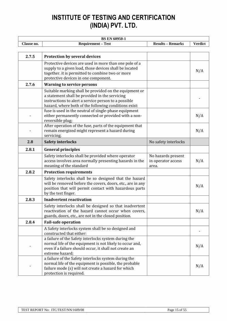
2.7.5 Protection by several devices
Protective devices are used in more than one pole of a supply to a given load, those devices shall be located together. it is permitted to combine two or more protective devices in one component.
N/A
2.7.6 Warning to service persons
Suitable marking shall be provided on the equipment or a statement shall be provided in the servicing instructions to alert a service person to a possible hazard, where both of the following conditions exist:
-
- fuse is used in the neutral of single-phase equipment either permanently connected or provided with a non-reversible plug;
N/A
- After operation of the fuse, parts of the equipment that remain energized might represent a hazard during servicing.
N/A
2.8 Safety interlocks No safety interlocks
2.8.1 General principles
Safety interlocks shall be provided where operator access involves area normally presenting hazards in the meaning of the standard
No hazards present in operator access area.
N/A
2.8.2 Protection requirements
Safety interlocks shall be so designed that the hazard will be removed before the covers, doors, etc., are in any position that will permit contact with hazardous parts by the test finger.
N/A
2.8.3 Inadvertent reactivation
Safety interlocks shall be designed so that inadvertent reactivation of the hazard cannot occur when covers, guards, doors, etc., are not in the closed position.
N/A
2.8.4 Fail-safe operation
A Safety interlocks system shall be so designed and constructed that either:
-
-
a failure of the Safety interlocks system during the normal life of the equipment is not likely to occur and, even if a failure should occur, it shall not create an extreme hazard;
N/A
-
a failure of the Safety interlocks system during the normal life of the equipment is possible, the probable failure mode (s) will not create a hazard for which protection is required.
N/A

INSTITUTE OF TESTING AND CERTIFICATION (INDIA) PVT. LTD.
BS EN 60950-1
Clause no. Requirement – Test Results – Remarks Verdict
TEST REPORT No: ITC/TEST/NN/1609/08 Page 16 of 55
2.8.5 Moving parts
Moving mechanical parts in mechanical and electromechanical Safety interlock systems shall have adequate endurance.
P
2.8.6 Overriding
It may be necessary for a service person to override a Safety interlock, the override system shall comply with all of the following:
-
- require an intentional effort to operate N/A
- reset automatically to normal operation when servicing is complete, or prevent normal operation unless the service person has reset the Safety interlock;
N/A
- require a tool for operation when in an operator access area and not be operable with the test finger, Figure 2A
N/A
-
not bypass a safety interlock for an extreme hazard unless another reliable means of safety protection becomes effective when the Safety interlock is thus bypassed.
N/A
2.8.7 Switches, relays and their related circuits
A switch in a Safety interlock system shall:
- conform to lEC 61058-1, with evaluation for 10000 operating cycles in accordance with 7.1.4.4 of IEC 61058-1;
N/A
- comply with 2.8.7.1 and pass the tests ol 2.8.7.3 and 2.9.7.4
N/A
- pass the tests of 2.8.7.2, 2.8.7.3 and 2.8.7.4. N/A
2.8.7.1 Separation distances for contact gaps and their related circuits
N/A
2.8.7.2 Overload test N/A
2.8.7.3 Endurance test N/A
2.8.7.4 Electric strength test N/A
2.8.8 Mechanical actuators
the actuating part in a mechanical Safety interlock system is relied upon for safety, precautions shall be taken to ensure that it is not overstressed
N/A
2.9 Electrical insulation
2.9.1 Properties of insulating materials
Natural rubber, asbestos or hygroscopic material are not used
P

INSTITUTE OF TESTING AND CERTIFICATION (INDIA) PVT. LTD.
BS EN 60950-1
Clause no. Requirement – Test Results – Remarks Verdict
TEST REPORT No: ITC/TEST/NN/1609/08 Page 17 of 55
2.9.2 Humidity conditioning P
Relative humidity (%), temperature (ºC)…….. Tested for 48hrs at 93% R.H, 25 ºC.
P
2.9.3 Grade of insulation
Insulation shall be considered to be functional insulation, basic insulation. Supplementary insulation, reinforced insulation or double insulation
-
2.9.4 Separation from hazardous voltages
Accessible conductive parts, including SELV Circuit, TNV Circuits and their related windings, are separated from parts at Hazardous voltage.
Only SELV DC supply is available
N/A
2.10 Clearances, creepage distances and distances through insulation
2.10.1 General P
2.10.1.1 Frequency DC operated equipment.
N/A
2.10.1 .2 Pollution degrees Pollution degrees 3 P
2.10.1.3 Reduced values for functional insulation N/A
2.10.1.4 intervening unconnected conductive parts
It is permitted for clearances and creepage distances to be divided by intervening, unconnected (floating) conductive parts, such as unused contacts of a connector.
N/A
2.10.1.5 lnsulation with varying dimensions
lf the insulation of a transformer has different working voltages along the length of the winding, it is permitted to vary clearances, creepage distances and distances through insulation accordingly.
N/A
2.10.1.6 Special separation requirements
The requirements of 2.10 and Annex G do not apply to separation provided to comply with 2.3.2 unless basic insulation is used, nor to separation provided to comply with 6.1.2 or 6.2.1.
N/A
2.10.1.7 lnsulation in circuits generating starting pulses
For a circuit generating starting pulses to ignite a discharge lamp, and if the circuit is a limited current circuit complying with 2.4, the requirements for functional insulation apply between the circuit and other conductive parts (see 5.3.4).
N/A

INSTITUTE OF TESTING AND CERTIFICATION (INDIA) PVT. LTD.
BS EN 60950-1
Clause no. Requirement – Test Results – Remarks Verdict
TEST REPORT No: ITC/TEST/NN/1609/08 Page 18 of 55
2.10.2 Determination of working voltage
2.10.2.1 General N/A
2.10.2.2 RMS working voltage N/A
2.10.2.3 Peak working voltage N/A
2.10.3 Clearances
2.10.3.1 General
CLEARANCES shall be so dimensioned that over voltages, including transients that may enter the equipment, and peak voltages that may be generated within the equipment, do not break down the clearance.
N/A
2.10.3.2 Mains transient voltages SELV DC supplied.
a) Ac mains supply N/A
b) Earthed Dc mains supply N/A
c) Unearthed Dc mains supply N/A
d) Battery operation N/A
2.10.3.3 Clearances in primary circuits N/A
2.10.3.4 Clearances in secondary circuits N/A
Minimum CLEARANCES in secondary circuits are determined from Table 2M.
N/A
2.10.3.5 Clearances in circuits having starting pulses
a circuit generating starting pulses to ignite a discharge lamp, and if the circuit is not a Limited current circuit complying with 2.4
N/A
2.10.3.6 Transients from an a.c. mains supply Not for connection to a.c. mains supply
N/A
2.10.3.7 Transients from a d.c. mains supply Not for connection to D.C. mains supply
N/A
2.10.3.8 Transients from telecommunication networks and cable distribution systems
lf the telecommunication network Transient voltage is known for the telecommunication network in question, it is permitted to use the known value in 2.10.3.4.
N/A

INSTITUTE OF TESTING AND CERTIFICATION (INDIA) PVT. LTD.
BS EN 60950-1
Clause no. Requirement – Test Results – Remarks Verdict
TEST REPORT No: ITC/TEST/NN/1609/08 Page 19 of 55
2.10.4 Creepage distances
2.10.4.1 General
Creepage distances shall be so dimensioned that, for a given RMS working voltage and pollution degree, no flashover or breakdown of insulation (for example, due to tracking) will occur.
N/A
2.10.4.2 Material group and comparative tracking index N/A
2.10.4.3 Minimum creepage distances
Creepage distances shall be not less than the appropriate minimum values specified in Table 2N.
N/A
2.10.5 Solid insulation
the requirements for Solid insulation (except those for thin sheet material) and for insulating compound also apply to gel materials
N/A
2.10.5.2 Distances through insulation
If a design is based on distances through insulation. these distances shall be dimensioned according to the application of the insulation (see 2.9) and as follows (see Figure F.14):
N/A
2.10.5.3 insulating compound as solid insulation
There is no minimum internal clearance or creeage distance if insulating compound completely fills the casing of a component or subassembly, provided that each distance through insulation in the component or subassembly meets the requirements of 2.10.5.2 and a single sample passes the tests of 2.10.10.
N/A
2.10.5.4 Semiconductor devices
There is no minimum distance through insulation for supplementary insulation or Reinforced insulation consisting of an insulating compound completely filling the casing of a semiconductor component
N/A
2.10.6 Construction of printed boards
2.10.6.1 Uncoated printed boards
The insulation between conductors on the outer surfaces of an uncoated printed board shall comply with the minimum CLEARANCE requirements of 2.10.3 (or Annex G) and the minimum creepage distance requirements of 2.10.4.
N/A
2.10.6.2 Coated printed boards
For printed boards whose outer surfaces are to be coated with a suitable coating material,
P

INSTITUTE OF TESTING AND CERTIFICATION (INDIA) PVT. LTD.
BS EN 60950-1
Clause no. Requirement – Test Results – Remarks Verdict
TEST REPORT No: ITC/TEST/NN/1609/08 Page 20 of 55
2.10.6.3 insulation between conductors on the same inner surface of a printed board
Inner surface of a multi-layer printed board (see Figure F.16), the path between any two conductors shall comply with the requirements for a cemented joint in 2.10.5.5
N/A
2.10.7 Component external terminations
It is permitted to use coatings over external terminations of components to increase effective clearances and creepage distances (see Figure F.10).
N/A
2.10.8 Tests on coated printed boards and coated components
2.10.8.1 Sample preparation and preliminary inspection
Three sample printed boards (or, for coated components in 2.10.7, two components and one board) identified as samples 1, 2 and 3 are required. lt is permitted to use either actual boards or specially produced samples with representative coating and minimum separations.
N/A
2.10.8.2 Thermal conditioning
Sample 2 is aged in a full draught oven at a temperature and for a time duration chosen from the graph of Figure 2J using the temperature index line that corresponds to the maximum operating temperature of the coated board
N/A
2.10.8.3 Electric strength test
Samples 1 and 2 (see 2.10.8.1) are then subjected to the humidity conditioning of 2.9.2 and shall withstand the relevant electric strength test of 5.2.2 between conductors.
N/A
2.10.8.4 Abrasion resistance test
Scratches are made across five pairs of conducting parts and the intervening separations at points where the separations will be subject to the maximum potential gradient during the tests.
N/A
2.10.9 Thermal cycling
The following thermal cycling sequence is used if required by 2.10.8.2, 2.10.10 or 2.10.11.
N/A

INSTITUTE OF TESTING AND CERTIFICATION (INDIA) PVT. LTD.
BS EN 60950-1
Clause no. Requirement – Test Results – Remarks Verdict
TEST REPORT No: ITC/TEST/NN/1609/08 Page 21 of 55
2.10.10 Test for Pollution Degree 1 environment and for insulating compound
N/A
2.10.11 Tests for semiconductor devices and for cemented joints
N/A
2.10.12 Enclosed and sealed parts N/A
3 Wiring, connections and supply
3.1 General
3.1.1 Current rating and over current protection
The cross-sectional area of internal wires and interconnected cables shall be adequate for the current they are intended to carry when the equipment is operating under normal load
P
3.1.2 Protection against mechanical damage
Wire ways shall be smooth and free from sharp edges. wires shall be protected so that they do not come into contact with burrs, cooling fins, moving parts, etc
Wire way is smooth and free from sharp edges.
P
3.1.3 Securing of internal wiring
internal wiring shall be routed, supported, clamped or secured in a manner that reduces the likelihood of:
-
- excessive strain on wire and on terminal connections; and
P
- loosening of terminal connections; and P
- damage of conductor insulation. P
3.1.4 lnsulation of conductors
Except as covered in 2.1.1.3 b), insulation of individual conductors of internal wiring shall fulfill the requirements of 2.10.5 and be capable of withstanding the applicable electric strength test specified in 5.2.2.
The insulation of individually conductors is suitable for the application
P
3.1.5 Beads and ceramic insulators
Beads and similar ceramic insulators on conductors shall:
No beads or similar ceramic insulators on conductors.
-
- be so fixed or supported that they cannot change their position in such a way that a hazard would be created
N/A
- not rest on sharp edges or sharp corners. N/A
3.1.6 Screws for electrical contact pressure
Electrical contact pressure is required, a screw shall engage at least two complete threads into a metal plate, a metal nut or a metal insert.
No screw for electrical contact pressure.
N/A

INSTITUTE OF TESTING AND CERTIFICATION (INDIA) PVT. LTD.
BS EN 60950-1
Clause no. Requirement – Test Results – Remarks Verdict
TEST REPORT No: ITC/TEST/NN/1609/08 Page 22 of 55
3.1.7 Insulating materials in electrical connections
Electrical connections, including those for protective earthing functions (see 2.6), shall be so designed that contact pressure is not transmitted through insulating material unless there is sufficient resilience in the metallic parts to compensate for any possible shrinkage or distortion of the insulating material.
No contact pressure through insulating material
N/A
3.1.8 Self-tapping and spaced thread screws
Spaced thread (sheet metal) screws shall not be used for the connection of current-carrying parts, unless they clamp these parts directly in contact with each other and are provided with a suitable means of locking.
N/A
3.1.9 Termination of conductors
It is permitted to use soldered, welded. crimped, screwless (push-In) and similar terminations for the connection of conductors. For soldered terminations, the conductor shall be positioned or fixed so that reliance is not placed upon the soldering alone to maintain The conductor in position.
All conductors are reliably secured
P
10 N pull test During this test no hazard occurred through conductors
P
3.1.10 Sleeving on wiring
Sleeving is used as supplementary insulation on internal wiring, it shall be retained in position by positive means.
P
3.2 Connection to a mains supply The equipment is not to be connected to mains supply.
3.2.1 Means of connection
3.2.1.1 Connection to an a.c. mains supply
For safe and reliable connection to an AC mains supply, equipment shall be provided with one of the following:
-
- terminals for permanent connection to the supply; N/A
- a non-detachable Power supply cord for permanent connection to the supply, or for connection to the supply by means of a plug;
N/A
- an appliance inlet for connection of a detachable power supply cord:
N/A
- a mains plug that is part of direct plug-in equipment. N/A

INSTITUTE OF TESTING AND CERTIFICATION (INDIA) PVT. LTD.
BS EN 60950-1
Clause no. Requirement – Test Results – Remarks Verdict
TEST REPORT No: ITC/TEST/NN/1609/08 Page 23 of 55
3.2.1.2 Connection to a d.c. mains supply
For safe and reliable connection to a d.c mains supply, equipment shall be provided with one of the following:
-
- terminals for permanent connection to the supply; N/A
- a non-detachable power supply cord for permanent connection to the Supply, or for connection to the supply by means of a plug;
N/A
- an appliance inlet for connection of a detachable power supply cord.
NA
3.2.2 Multiple supply connections
lf equipment is provided with more than one supply connection (for example, with different voltages or frequencies or as backup power), the design shall be such that all of the following conditions are met:
N/A
- separate means of connection are provided for different circuits; and
N/A
- supply plug connections, if any, are not interchangeable if a hazard could be created by incorrect plugging; and
N/A
- bare parts of an ELV circuit or parts at hazardous voltages, such as plug contacts, are not accessible to an operator when one or more connectors are disconnected.
N/A
3.2.3 Permanently connected equipment
Permanently connected equipment shall be provided with either:
-
- a set of terminals as specified in 3.3; or N/A
- a non-detachable power supply cord. N/A
3.2.4 Appliance inlets
Appliance inlets shall meet all of the following: -
-
be so located or enclosed that parts at hazardous voltage are not accessible insertion or removal of the connector (appliance inlets complying with IEC 60309 IEC 60320 are considered lo comply with this requirement); and
N/A
- be so located that the connector can be inserted without difficulty; and
N/A
- be so located that, after insertion of the connector, the equipment is not supported by the connector for any position of normal use on a flat surface.
N/A

INSTITUTE OF TESTING AND CERTIFICATION (INDIA) PVT. LTD.
BS EN 60950-1
Clause no. Requirement – Test Results – Remarks Verdict
TEST REPORT No: ITC/TEST/NN/1609/08 Page 24 of 55
3.2.5 Power supply cords
3.2.5.1 AC power supply cords
A mains supply cord shall be of the sheathed type and comply with the following as appropriate:
-
-
if rubber sheathed, be of synthetic rubber and not lighter than ordinary tough rubber-sheathed flexible cord according to IEC 60245-1 (designation 60245 IEC 53):
N/A
- if PVC sheathed: N/A
. for equipment provided with a non-detachable Power supply cord and having a mass not exceeding 3 kg, be not lighter than light pvc sheathed flexible cord according to IEC 60227-1:2007
N/A
. for equipment provided with a non-detachable Power supply cord and having a mass exceeding 3 kg, be not lighter than ordinary pvc sheathed flexible cord according to IEC 60227-1:2007
N/A
. for equipment provided with a detachable power supply cord, be not lighter than light pvc sheathed flexible cord according to IEC 60227 -1.2007
N/A
. for screened cords of moveable equipment, the flexing test of 3.1 of IEC 60227 -2:1997;
N/A
3.2.5.2 DC power supply cords
A power supply cord for connection to the d.c mains supply shall be suitable for the voltage, current and the physical abuses it is likely to encounter.
N/A
3.2.6 Cord anchorages and strain relief
For equipment with a non-detachable Power supply cord, a cord anchorage shall be supplied such that
-
- the connecting points of the cord conductors are relieved from strain, and
N/A
- the outer covering of the cord is protected from abrasion.
N/A
3.2.7 Protection against mechanical damage
Power supply cords shall not be exposed to sharp points or cutting edges within or on the surface of the equipment, or at the inlet opening or inlet bushing.
N/A
3.2.8 Cord guards
A cord guard shall be provided at the power supply cord inlet opening of equipment that has a non-detachable Power supply cord, and which is hand-held equipment or is intended to be moved while in operation.
N/A

INSTITUTE OF TESTING AND CERTIFICATION (INDIA) PVT. LTD.
BS EN 60950-1
Clause no. Requirement – Test Results – Remarks Verdict
TEST REPORT No: ITC/TEST/NN/1609/08 Page 25 of 55
3.2.9 Supply wiring space
The supply wiring space provided inside, or as part of, the equipment for permanent connection or for connection of an ordinary non-detachable power supply cord.
N/A
3.3 Wiring terminals for connection of external conductors
No external connection required
3.3.1 Wiring terminals
Permanently connected equipment and equipment with ordinary non-detachable power supply cords shall be provided with terminals in which connection is made by means of screws, nuts or equally effective devices (see also 2.6.4).
N/A
3.3.2 Connection of non-detachable power supply cords
For equipment with special non-detachable power supply cords, the connection of the individual conductors to the internal wiring of the equipment shall be accomplished by any means that will provide a reliable electrical and mechanical connection without exceeding the permitted temperature limits while the equipment is operated under normal load(see also 3.1.9).
N/A
3.3.3 Screw terminals
Screws and nuts that clamp external mains supply conductors shall have a thread conforming to ISO 261 or ISO 262.
N/A
3.3.4 Conductor sizes to be connected
Terminals shall allow the connection of conductors having nominal cross-sectional areas as shown in Table 3D.
N/A
3.3.5 Wiring terminal sizes
Pillar, stud or screw type terminals shall comply with the minimum sizes in Table 3E.
N/A
3.3.6 Wiring terminal design
Wiring terminals shall be so designed that they clamp the conductor between metal surfaces with sufficient contact pressure and without damage to the conductor.
N/A
3.3.7 Grouping of wiring terminals
For ordinary non-detachable power supply cords and for permanently connected equipment, all associated a.c mains supply terminals shall be located in proximity to each other and to the main protective earthing terminal.
N/A

INSTITUTE OF TESTING AND CERTIFICATION (INDIA) PVT. LTD.
BS EN 60950-1
Clause no. Requirement – Test Results – Remarks Verdict
TEST REPORT No: ITC/TEST/NN/1609/08 Page 26 of 55
3.3.8 Stranded wire
The end of a stranded conductor shall not be consolidated by soft soldering at places where the conductor is subject to contact pressure unless the method of clamping is designed so as to reduce the likelihood of a bad contact due to cold flow of the solder.
N/A
3.4 Disconnection from the mains supply No connection to mains required.
3.4.1 General requirement
A disconnect device or devices shall be provided to disconnect the equipment from the mains supply for servicing.
N/A
3.4.2 Disconnect devices
equipment intended to be powered from an a.c mains supply that is Overvoltage Category l, Overvoltage Category ll or Overvoltage Category lll, or from a d.c mains supply that is at a hazardous voltage, a disconnect device shall have a contact separation of at least 3 mm.
N/A
3.4.3 Permanently connected equipment
For Permanently connected equipment, the disconnect device shall be incorporated in the equipment, unless the equipment is accompanied by installation instructions in accordance with 1.7.2.1, stating that an appropriate disconnect device shall be provided external to the equipment.
N/A
3.4.4 Parts which remain energized
Parts on the supply side of a disconnect device in the equipment which remain energized when the disconnect device is switched off shall be guarded so as to reduce the likelihood of accidental contact by a service person.
N/A
3.4.5 Switches in flexible cords
Isolating switches shall not be fitted in flexible cords. N/A
3.4.6 Number of poles-single-phase and d.c, equipment
A disconnect device, if provided in or as part of the equipment, shall disconnect both poles simultaneously
N/A
3.4.7 Number of poles - three-phase equipment
For three-phase equipment, the disconnect device shall disconnect simultaneously all line conductors of the a.c mains supply
N/A
INSTITUTE OF TESTING AND CERTIFICATION (INDIA) PVT. LTD.
BS EN 60950-1
Clause no. Requirement – Test Results – Remarks Verdict
TEST REPORT No: ITC/TEST/NN/1609/08 Page 27 of 55
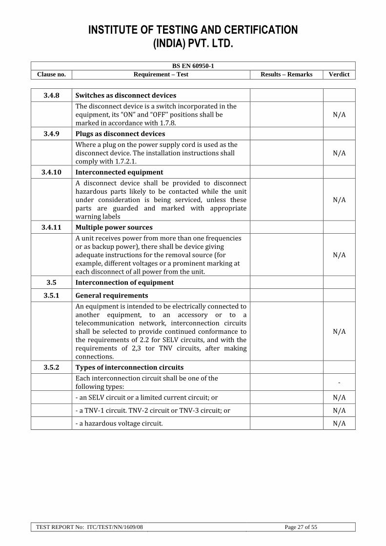
3.4.8 Switches as disconnect devices
The disconnect device is a switch incorporated in the equipment, its “ON” and “OFF’’ positions shall be marked in accordance with 1.7.8.
N/A
3.4.9 Plugs as disconnect devices
Where a plug on the power supply cord is used as the disconnect device. The installation instructions shall comply with 1.7.2.1.
N/A
3.4.10 Interconnected equipment
A disconnect device shall be provided to disconnect hazardous parts likely to be contacted while the unit under consideration is being serviced, unless these parts are guarded and marked with appropriate warning labels
N/A
3.4.11 Multiple power sources
A unit receives power from more than one frequencies or as backup power), there shall be device giving adequate instructions for the removal source (for example, different voltages or a prominent marking at each disconnect of all power from the unit.
N/A
3.5 Interconnection of equipment
3.5.1 General requirements
An equipment is intended to be electrically connected to another equipment, to an accessory or to a telecommunication network, interconnection circuits shall be selected to provide continued conformance to the requirements of 2.2 for SELV circuits, and with the requirements of 2,3 tor TNV circuits, after making connections.
N/A
3.5.2 Types of interconnection circuits
Each interconnection circuit shall be one of the following types:
-
- an SELV circuit or a limited current circuit; or N/A
- a TNV-1 circuit. TNV-2 circuit or TNV-3 circuit; or N/A
- a hazardous voltage circuit. N/A

INSTITUTE OF TESTING AND CERTIFICATION (INDIA) PVT. LTD.
BS EN 60950-1
Clause no. Requirement – Test Results – Remarks Verdict
TEST REPORT No: ITC/TEST/NN/1609/08 Page 28 of 55
3.5.3 ELV circuits as interconnection circuits
Additional equipment is specifically complementary to the host (first) equipment (for example, a collator for a copying machine) ELV circuits are permitted as interconnection circuits between the equipments, provided that the equipments continue to meet the requirements of this standard when connected together.
N/A
3.5.4 Data ports for additional equipment
Limit the risk of fire in an additional equipment or accessory (for example, a scanner, mouse, keyboard, DVD drive, CD ROM drive or joystick), SELV circuits of a data port for connection of such equipment shall be supplied by a limited power source that complies with 2.5. This requirement does not apply if it is known that the additional equipment complies with 4.7.
N/A
4 Physical requirements
4.1 Stability
Under conditions of normal use, units and equipment shall not become physically unstable to the degree that they could become a hazard to an operator or to a service person.
Mass < 7kg. N/A
4.2 Mechanical strength
4.2.1 General
Equipment shall have adequate mechanical strength and shall be so constructed that no hazard is created in the meaning of this standard when subjected to handling as may be expected.
P
4.2.2 Steady force test,10 N
Components and parts, other than parts serving as an enclosure (see 4.2.9 and 4.2.4), are subjected to a steady force of 10 N ±1 N.
P
4.2.3 Steady force test, 30 N
Parts of an enclosure located in an operator access area, which are protected by a cover or door meeting the requirements of 4.2.4, are subjected to a steady force of 30 N ±3 N for a period of 5 s, applied by means of a straight unjointed version of the test finger.
P

INSTITUTE OF TESTING AND CERTIFICATION (INDIA) PVT. LTD.
BS EN 60950-1
Clause no. Requirement – Test Results – Remarks Verdict
TEST REPORT No: ITC/TEST/NN/1609/08 Page 29 of 55
4.2.4 Steady force test, 250 N
External enclosures are subjected to a steady force of 250N±10N for a period of 5s, applied in turn to the top, bottom and sides of the enclosure fitted to the equipment, by means of a suitable test tool providing contact over a circular plane surface 30 mm in diameter. However, this test is not applied to the bottom of an enclosure of equipment having a mass of more than 18 kg.
P
4.2.5 lmpact test
Except for equipment identified in 4.2.6, external surfaces of enclosures, the failure of which would give access to hazardous parts,
P
4.2.6 Drop test
The following equipment is subjected to a drop test:
- Hand- held equipment; P
- Direct plug in equipment; N/A
- Transportable equipment ; N/A
- desktop equipment having a mass of 5 kg or less that is intended for use with any one of the following:
N/A
- a cord-connected telephone handset, or N/A
- another cord-connected hand-held accessory with an acoustic function, or
N/A
- a headset: N/A
- Movable equipment requiring lifting or handling by the user as part of its intended use.
N/A
4.2.7 Stress relief test
Enclosures of molded or formed thermoplastic materials shall be so constructed that any shrinkage or distortion of the material due to release of internal stresses caused by the molding or forming operation does not result in the exposure of hazardous parts or in the reduction of clearances or creepage distances below the values specified in 2.10
N/A
4.2.8 Cathode ray tubes
lf a cathode ray tube having a maximum face dimension exceeding 160 mm is included in the equipment, either the cathode ray tube or the enclosure with the cathode ray tube correctly installed shall comply with the requirements of clause 18 of IEC 60065 for mechanical strength of cathode ray tubes.
N/A

INSTITUTE OF TESTING AND CERTIFICATION (INDIA) PVT. LTD.
BS EN 60950-1
Clause no. Requirement – Test Results – Remarks Verdict
TEST REPORT No: ITC/TEST/NN/1609/08 Page 30 of 55
4.2.9 High pressure lamps
The mechanical enclosure of a high pressure lamp shall have adequate strength to contain an explosion of the lamp so as to reduce the likelihood of harm to an operator or person near the equipment during normal use or operator servicing.
N/A
4.2.10 Wall or ceiling mounted equipment
The mounting means of equipment intended for wall or ceiling mounting shall be adequate.
N/A
4.3 Design and construction
4.3.1 Edges and corners
Edges or corners could be hazardous to operators because of location or application in the equipment, they shall be rounded or smoothed.
No Sharp edges found
P
4.3.2 Handles and manual controls
Handles, knobs, grips, levers and the like shall be reliably fixed so that they will not work loose in normal use, if this might create a hazard. Sealing compounds and the like, other than self-hardening resins, shall not be used to prevent loosening.
P
4.3.3 Adjustable controls
Equipment shall be so constructed that manual adjustment of a control device, such as device for selection of different a.c mains supply voltages, requires the use of a tool incorrect setting or inadvertent adjustment might create a hazard.
N/A
4.3.4 Securing of parts
Screws, nuts, washers, springs or similar parts shall be secured so as to withstand mechanical stresses occurring in normal use if loosening would create a hazard, or if Clearances or creepage distances for supplementary insulation or reinforced insulation would be reduced below the values specified in 2.10
P
4.3.5 Connection by plugs and sockets
A manufacturer's unit or system, plugs and sockets likely to be used by the operator or by a service person shall not be employed in a manner likely to create a hazard due to misconnection
N/A

INSTITUTE OF TESTING AND CERTIFICATION (INDIA) PVT. LTD.
BS EN 60950-1
Clause no. Requirement – Test Results – Remarks Verdict
TEST REPORT No: ITC/TEST/NN/1609/08 Page 31 of 55
4.3.6 Direct plug-in equipment
Direct plug-in equipment shall not impose undue stress on the socket-outlet. The mains plug part shall comply with the standard for the relevant mains plug.
N/A
4.3.7 Heating elements in earthed equipment
The temperature sensing devices shall also disconnect the neutral conductor for each of the following cases:
-
a) in equipment supplied from an lT power distribution system;
N/A
b) in pluggable equipment supplied through a reversible appliance coupler or a reversible plug;
N/A
c) in equipment supplied from a socket- outlet with indeterminate polarity.
N/A
4.3.8 Batteries
Portable secondary sealed cells and batteries (other than button) containing alkaline or other non-acid electrolyte shall comply with IEC 62133.
- Rechargeable battery; 18650 Rechargeable battery 2400mAh 7.2V
P
- non-rechargeable batteries, 9V Dry Battery used P
- Reverse charging of a rechargeable battery N/A
4.3.9 Oil and grease
Internal wiring, windings, commutators, slip-rings and the like, and insulation in general, are exposed to oil, grease or similar substances, the insulation shall have adequate properties to resist deterioration under these conditions.
N/A
4.3.10 Dust, powders, liquids and gases
Equipment producing dust (for example, paper dust) or using powders, liquids or gases shall be so constructed that it is unlikely that either a dangerous concentration of these materials or a hazard in the meaning of this standard will be created by condensation, vaporization, leakage, spillage or corrosion during normal operation, storage, filling or emptying.
N/A
4.3.11 Containers for liquids or gases
Equipment that, in normal use, contains liquids or gases shall incorporate adequate safeguards against build-up of excessive pressure.
N/A

INSTITUTE OF TESTING AND CERTIFICATION (INDIA) PVT. LTD.
BS EN 60950-1
Clause no. Requirement – Test Results – Remarks Verdict
TEST REPORT No: ITC/TEST/NN/1609/08 Page 32 of 55
4.3.12 Flammable liquids
lf a flammable liquid is used in equipment, the liquid shall be kept in a closed reservoir, except for the amount needed for the functioning of the equipment. The maximum quantity of flammable liquid stored in an equipment shall in general be not more than 5 l.
N/A
4.3.13 Radiation
4.3.13.1 General
Equipment shall be so designed that the risk of harmful effects of radiation to persons, and damage to materials affecting safety, is reduced.
N/A
4.3.13.2 lonizing radiation
For equipment that generates ionizing radiation, compliance is checked by the test in Annex H.
N/A
4.3.13.3 Effect of ultraviolet(UV) radiation on materials
only to equipment containing lamps that produce significant UV radiation, that is, having emission predominantly in the spectrum 180 nm to 400 nm, as specified by the lamp manufacturer.
N/A
4.3.13.4 Human exposure to ultraviolet (UV) radiation
The following requirements apply only to equipment containing lamps that produce significant UV radiation,that is having emission predominantly in the spectrum 180 nm to 400 nm as specified by the lamp manufacturer.
N/A
4.3.13.5 Lasers (including laser diodes) and LEDs
4.3.13.5.1 Lasers (including laser diodes)
Except as permitted below, equipment shall be classified and labeled according to IEC 60825-1, IEC 60825-2 and IEC 60825-12, as applicable.
N/A
4.3.13.5.2 Light emitting diodes (LEDS)
Equipment containing LEDs that produce optical radiation in excess of the limits specified in IEC 62471 in the wavelength range 200 nm to 3 000 nm, as specified by the lamp manufacturer, shall be provided with means (such as an interlock. barriers, guards or the equivalent) to reduce the likelihood of optical radiation exceeding the limits specified in IEC 62471
LEDs in this equipment are used for indicating function with low optical power.
P

INSTITUTE OF TESTING AND CERTIFICATION (INDIA) PVT. LTD.
BS EN 60950-1
Clause no. Requirement – Test Results – Remarks Verdict
TEST REPORT No: ITC/TEST/NN/1609/08 Page 33 of 55
4.4 Protection against hazardous moving parts
4.4.1 General
Moving fan blades, hazardous moving parts moving parts of the equipment (which means moving parts that have the potential to cause injury) shall be so arranged, enclosed or guarded to reduce the risk of injury to persons. Moving fan blades are evaluated in as accordance with 4.4.5.
During operation no risk of personal injury possible.
P
4.4.2 Protection in operator access areas
Protection shall be provided by a suitable construction reducing the likelihood of access to hazardous moving parts, or by locating the moving parts in an enclosure provided with mechanical or electrical safety interlocks that remove the hazard when access is gained
P
4.4.3 Protection in restricted access locations
For equipment to be installed in a restricted access location, the requirements compliance criteria in 4.4.2 for operator access areas apply.
N/A
4.4.4 Protection in service access areas
A service access area, protection shall be provided such that unintentional contact with hazardous moving parts is unlikely during servicing operations involving other parts of the equipment.
P
4.4.5 Protection against moving fan blades No moving fan Blades
4.4.5.1 General
Equipment shall be so constructed that the likelihood of injury from moving fan blades has been minimized.
N/A
4.4.5.2 Protection for users
A moving fan blade classified as 4.4.5.1 a) may be located in an operator access area. Under a single fault condition, a moving fan blade classified as 4.4.5.1 a) may reach the limits permitted for a moving fan blade classified as 4.4.5.1 b).
N/A
4.4.5.3 Protection for service persons
No equipment protection from moving fan blades is required for the protection for service person.
N/A
4.5 Thermal requirements
4.5.1 General

INSTITUTE OF TESTING AND CERTIFICATION (INDIA) PVT. LTD.
BS EN 60950-1
Clause no. Requirement – Test Results – Remarks Verdict
TEST REPORT No: ITC/TEST/NN/1609/08 Page 34 of 55
4.5.2 Temperature tests
Materials used in components and in the construction of the equipment shall be selected so that under normal load, temperatures do not exceed safe values in the meaning of this standard.
P
4.5.3 Temperature limits for materials
The temperature of materials and components shall not exceed the values shown in Table 48
N/A
4.5.4 Touch temperature limits
The temperatures of accessible parts in operator access areas shall not exceed the values shown in Table 4C.
See Table 4 P
4.5.5 Resistance to abnormal heat
Thermoplastic parts on which parts at hazardous voltage are directly mounted shall be resistant to abnormal heat.
N/A
4.6 Openings in enclosures
4.6.1 Top and side openings
For equipment that is intended to be used in more than one orientation (see1.3.6), the requirements of 4.6.1 apply in each
P
4.6.2 Bottoms of fire enclosures
For equipment that is intended to be used in more than one orientation (see 1.3.6), the requirements of 4.6.2 apply in each appropriate orientation.
N/A
4.6.3 Doors or covers in fire enclosures
lf part of a FIRE enclosure consists of a door or cover leading to an operator access area, it shall comply with one of the following requirements:
-
- the door or cover shall be interlocked to comply with the requirements in 2.8;
N/A
- a door or cover, intended to be routinely opened by the operator, shall comply with both of the following conditions:
N/A
- it shall not be removable from other parts of the fire enclosure by the operator; and
N/A
- it shall be provided with a means to keep it closed during normal operation;
N/A
-
a door or cover intended only for occasional use by the operator, such as for the installation of accessories, is permitted to be removable provided that the operating instructions include directions for correct removal and reinstallation of the door or cover.
N/A

INSTITUTE OF TESTING AND CERTIFICATION (INDIA) PVT. LTD.
BS EN 60950-1
Clause no. Requirement – Test Results – Remarks Verdict
TEST REPORT No: ITC/TEST/NN/1609/08 Page 35 of 55
4.6.4 Openings in transportable equipment
The risk of ignition caused by small metallic objects, such as paper clips or staples, moving around inside transportable equipment during transportation shall be reduced by measures to minimize the likelihood of such objects entering the equipment and bridging bare, conductive parts that may result in a fire hazard. Except as required in 4.6.4.3, provision of such measures is not required for bare conductive parts between which the power is limited in accordance with 2.5.
No transportable equipment
N/A
4.6.4.1 Constructional design measures
Examples of acceptable constructional design measures are:
-
- providing openings that do not exceed 1 mm in width regardless of length; or
N/A
-
providing a screen having a mesh with openings not greater than 2 mm between centre lines and constructed with a thread or wire diameter of not less than 0,45 mm; or
N/A
- providing internal barriers; or N/A
- other equivalent constructional means. N/A
4.6.4.2 Evaluation measures for larger openings
Openings larger than specified in 4.6.4.1 are permitted (see also 2.1.1.1), provided that fault testing is conducted to simulate bridging along a direct straight path between bare conductive parts (for metallized parts, see 4.6.4.3) located less than 13 mm away from each other in all areas within the equipment that do not meet the criteria of 4.6.4..1.
N/A
4.6.4.3 Use of metallized parts
Where metallized parts of a plastic barrier or enclosure are within 13 mm of parts of circuits where the available power is greater than 15 VA, one of the following requirements a) or b) or c) applies
-
a) access by a foreign metallic object shall be limited in accordance with 4.6.4.1, whether or not the available power meets the limits of 2.5; or
N/A
b) there shall be a barrier between the bare conductive parts and the metallized barrier or enclosure ; or
N/A
c)
fault testing shall be conducted to simulate bridging along a direct path between a bare conductive part and the nearest metallized part of a barrier or enclosure that is within 13 mm of the bare conductive part.
N/A

INSTITUTE OF TESTING AND CERTIFICATION (INDIA) PVT. LTD.
BS EN 60950-1
Clause no. Requirement – Test Results – Remarks Verdict
TEST REPORT No: ITC/TEST/NN/1609/08 Page 36 of 55
4.6.5 Adhesives for constructional purposes
lf a barrier or screen provided to comply with 4.6.1, 4.6.2 or 4.6.4 is secured with adhesive to the inside of the enclosure or to other parts inside the enclosure , the adhesive shall have adequate bonding properties throughout the life of the equipment.
N/A
4.7 Resistance to fire
This subclause specifies requirements intended to reduce the risk of ignition and the spread of flame, both within the equipment and to the outside, by the appropriate use of materials and components and by suitable construction.
N/A
4.7.1 Reducing the risk of ignition and spread of flame
For equipment or a portion of equipment, there are two alternative methods of providing protection against ignition and spread of flame that could affect materials, wiring, wound components and electronic components such as integrated circuits, transistors, thyristors, diodes, resistors and capacitors
N/A
Method 1,- selection and application of components wiring and materials
N/A
Method 2,- Application of all of simulated fault condition tests
N/A
4.7.2 Conditions for a fire enclosure
A fire enclosure is required when temperatures of parts under fault conditions could be sufficient for ignition.
-
4.7.2.1 Parts requiring a fire enclosure N/A
4.7.2.2 Parts not requiring a fire enclosure N/A
4.7.3 Materials
4.7.3.1 General
Enclosures, components and other parts shall be so constructed, or shall make use of such materials, that the propagation of fire is limited.
P
4.7.3.2 Materials for fire enclosures N/A
4.7.3.3 Materials for components and other parts outside fire enclosures
N/A
INSTITUTE OF TESTING AND CERTIFICATION (INDIA) PVT. LTD.
BS EN 60950-1
Clause no. Requirement – Test Results – Remarks Verdict
TEST REPORT No: ITC/TEST/NN/1609/08 Page 37 of 55
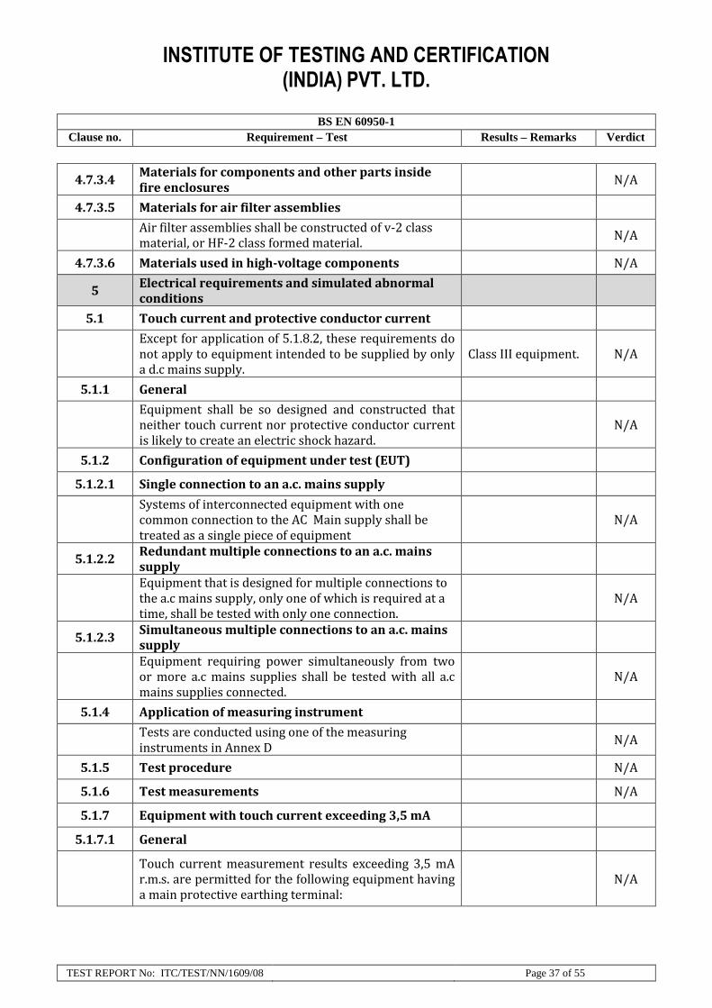
4.7.3.4 Materials for components and other parts inside fire enclosures
N/A
4.7.3.5 Materials for air filter assemblies
Air filter assemblies shall be constructed of v-2 class material, or HF-2 class formed material.
N/A
4.7.3.6 Materials used in high-voltage components N/A
5 Electrical requirements and simulated abnormal conditions
5.1 Touch current and protective conductor current
Except for application of 5.1.8.2, these requirements do not apply to equipment intended to be supplied by only a d.c mains supply.
Class III equipment. N/A
5.1.1 General
Equipment shall be so designed and constructed that neither touch current nor protective conductor current is likely to create an electric shock hazard.
N/A
5.1.2 Configuration of equipment under test (EUT)
5.1.2.1 Single connection to an a.c. mains supply
Systems of interconnected equipment with one common connection to the AC Main supply shall be treated as a single piece of equipment
N/A
5.1.2.2 Redundant multiple connections to an a.c. mains supply
Equipment that is designed for multiple connections to the a.c mains supply, only one of which is required at a time, shall be tested with only one connection.
N/A
5.1.2.3 Simultaneous multiple connections to an a.c. mains supply
Equipment requiring power simultaneously from two or more a.c mains supplies shall be tested with all a.c mains supplies connected.
N/A
5.1.4 Application of measuring instrument
Tests are conducted using one of the measuring instruments in Annex D
N/A
5.1.5 Test procedure N/A
5.1.6 Test measurements N/A
5.1.7 Equipment with touch current exceeding 3,5 mA
5.1.7.1 General
Touch current measurement results exceeding 3,5 mA r.m.s. are permitted for the following equipment having a main protective earthing terminal:
N/A

INSTITUTE OF TESTING AND CERTIFICATION (INDIA) PVT. LTD.
BS EN 60950-1
Clause no. Requirement – Test Results – Remarks Verdict
TEST REPORT No: ITC/TEST/NN/1609/08 Page 38 of 55
- stationary permanently connected equipment; N/A
- stationary pluggable equipment type B: N/A
- stationary pluggable equipment type A with a single connection to the a.c mains supply, and provided with a separate protective earthing terminal
N/A
- Movable of stationary pluggable equipment type A N/A
5.1.7.2 Simultaneous multiple connections to the supply N/A
5.1.8 Touch currents to telecommunication networks and cable distribution systems and from telecommunication networks
N/A
5.1.8.1 Limitation of the touch current to a telecommunication network or to a cable distribution system
The Touch current from equipment supplied from the a.c mains supply to a telecommunication network or to a cable distribution system shall be limited.
N/A
5.1.8.2 Summation of touch currents from telecommunication networks
EUT that provides telecommunication networks connection ports for connection of multiple items of other telecommunication equipment, shall not create a hazard for users and telecommunication network service persons due to Summation of touch current.
N/A
a) EUT with earthed telecommunication ports N/A
b) EUT whose telecommunication ports have no reference to protective earth
N/A
5.2 Electric strength
5.2.1 General Class III equipment.
The electric strength of the solid insulation used in the equipment shall be adequate.
N/A

INSTITUTE OF TESTING AND CERTIFICATION (INDIA) PVT. LTD.
BS EN 60950-1
Clause no. Requirement – Test Results – Remarks Verdict
TEST REPORT No: ITC/TEST/NN/1609/08 Page 39 of 55
5.2.2 Test procedure
The insulation is subjected either to a voltage of substantially sine-wave form having a frequency of 50 Hz or 60 Hz, or to a d.c. test voltage equal to the peak voltage of the prescribed a.c. test voltage.
N/A
5.3 Abnormal operating and fault conditions
5.3.1 Protection against overload and abnormal operation
Equipment shall be so designed that the risk of fire or electric shock due to mechanical or electrical overload or failure, or due to abnormal operation or careless use, is limited as far as practicable.
P
5.3.2 Motors
Under overload, Iocked rotor and other abnormal conditions, motors shall not create a hazard due to excessive temperatures.
In compliance P
5.3.3 Transformers
Transformers shall be protected against overload, for example, by
No Transformer N/A
- over current protection, N/A
- internal thermal cut-outs, or N/A
- use of current limiting transformers. N/A
5.3.4 Functional insulation
For Functional insulation, clearances and creepage distances shall satisfy one of the following requirements a) or b) or c).
-
a) They meet the clearances and creepage distances requirements for Functional insulation in 2.10 (or Annex G).
N/A
b) They withstand the electric strength tests for Functional insulation in 5.2.2.
N/A
c) They are short-circuited where a short-circuit could cause
N/A
5.3.5 Electromechanical components N/A
5.3.6 Audio amplifiers in information technology equipment
N/A
5.3.7 Simulation of faults P
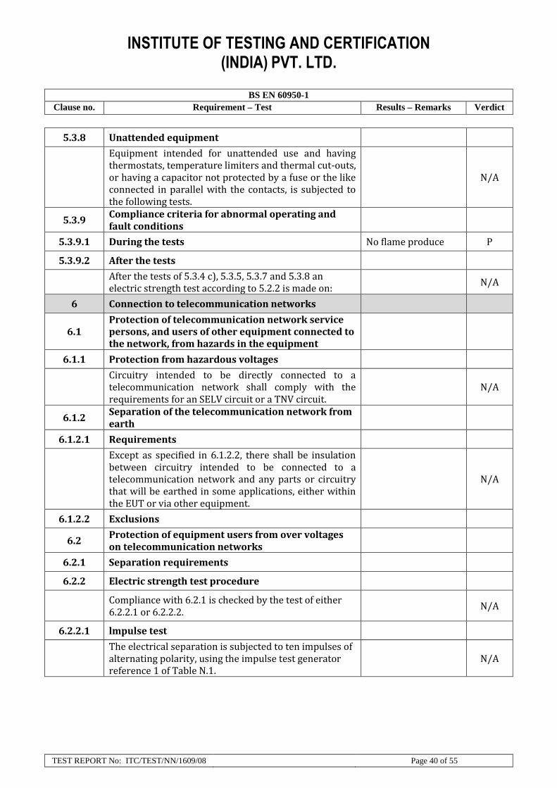
INSTITUTE OF TESTING AND CERTIFICATION (INDIA) PVT. LTD.
BS EN 60950-1
Clause no. Requirement – Test Results – Remarks Verdict
TEST REPORT No: ITC/TEST/NN/1609/08 Page 40 of 55
5.3.8 Unattended equipment
Equipment intended for unattended use and having thermostats, temperature limiters and thermal cut-outs, or having a capacitor not protected by a fuse or the like connected in parallel with the contacts, is subjected to the following tests.
N/A
5.3.9 Compliance criteria for abnormal operating and fault conditions
5.3.9.1 During the tests No flame produce P
5.3.9.2 After the tests
After the tests of 5.3.4 c), 5.3.5, 5.3.7 and 5.3.8 an electric strength test according to 5.2.2 is made on:
N/A
6 Connection to telecommunication networks
6.1 Protection of telecommunication network service persons, and users of other equipment connected to the network, from hazards in the equipment
6.1.1 Protection from hazardous voltages
Circuitry intended to be directly connected to a telecommunication network shall comply with the requirements for an SELV circuit or a TNV circuit.
N/A
6.1.2 Separation of the telecommunication network from earth
6.1.2.1 Requirements
Except as specified in 6.1.2.2, there shall be insulation between circuitry intended to be connected to a telecommunication network and any parts or circuitry that will be earthed in some applications, either within the EUT or via other equipment.
N/A
6.1.2.2 Exclusions
6.2 Protection of equipment users from over voltages on telecommunication networks
6.2.1 Separation requirements
6.2.2 Electric strength test procedure
Compliance with 6.2.1 is checked by the test of either 6.2.2.1 or 6.2.2.2.
N/A
6.2.2.1 lmpulse test
The electrical separation is subjected to ten impulses of alternating polarity, using the impulse test generator reference 1 of Table N.1.
N/A
INSTITUTE OF TESTING AND CERTIFICATION (INDIA) PVT. LTD.
BS EN 60950-1
Clause no. Requirement – Test Results – Remarks Verdict
TEST REPORT No: ITC/TEST/NN/1609/08 Page 41 of 55
6.2.2.2 Steady-state test
The electrical separation is subjected to an electric strength fest according to 5.2.2.
N/A
6.2.2.3 Compliance criteria
During the tests of 6.2.2.1 and 6.2.2.2, there shall be no breakdown of insulation.
N/A
6.3 Protection of the telecommunication wiring system from overheating
7 Connection to cable distribution systems
7.1 General
lf the equipment is to be connected to a cable distribution system, the requirements of Clause 7 apply in addition to the requirements of Clauses 1 to 5 of this standard.
N/A
7.2
Protection of cable distribution system service persons, and users of other equipment connected to the system, from hazardous voltages in the equipment
7.3 Protection of equipment users from over voltages on the cable distribution system
7.4 lnsulation between primary circuits and cable distribution systems
7.4.1 General
The insulation between the primary circuit and the terminal or lead provided for the connection of a cable distribution system pass either:
-
- the voltage surge test of 7.4.2 tot equipment intended to be connected to outdoor antennas; or
N/A
- the impulse test of 7.4.3 for equipment intended to be connected to other cable distribution systems.
N/A
7.4.2 Voltage surge test
The test is applied between the supply circuit terminals and the main protective earthing terminal.
N/A
7.4.3 lmpulse test
The test is applied between the supply circuit terminals and the main protective earthing terminal,
N/A
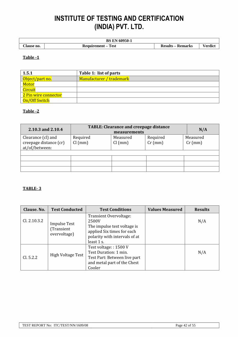
INSTITUTE OF TESTING AND CERTIFICATION (INDIA) PVT. LTD.
BS EN 60950-1
Clause no. Requirement – Test Results – Remarks Verdict
TEST REPORT No: ITC/TEST/NN/1609/08 Page 42 of 55
Table -1 1.5.1 Table 1: list of parts
Object/part no. Manufacturer / trademark Motor
Circuit 2 Pin wire connector On/Off Switch
Table -2
2.10.3 and 2.10.4 TABLE: Clearance and creepage distance
measurements N/A
Clearance (cl) and creepage distance (cr) at/of/between:
Required Cl (mm)
Measured Cl (mm)
Required Cr (mm)
Measured Cr (mm)
TABLE- 3
Clause. No. Test Conducted Test Conditions Values Measured Results
Cl. 2.10.3.2 Impulse Test (Transient overvoltage)
Transient Overvoltage: 2500V The impulse test voltage is applied Six times for each polarity with intervals of at least 1 s.
N/A
Cl. 5.2.2
High Voltage Test
Test voltage: : 1500 V Test Duration: 1 min. Test Part: Between live part and metal part of the Chest Cooler
N/A

INSTITUTE OF TESTING AND CERTIFICATION (INDIA) PVT. LTD.
BS EN 60950-1
Clause no. Requirement – Test Results – Remarks Verdict
TEST REPORT No: ITC/TEST/NN/1609/08 Page 43 of 55
TABLE- 4
4.5, 4.5.4 Thermal Requirement (Touch Temperature limit.) P
Measured temperature of parts Maximum allowed temperature (°C)
Measured temperature (°C)
External surface of metal part of controller
70°C 25.7
External surface of metal part of Motor
70°C 30.2
Handle, Knobs, Grips, etc. (Plastic, Rubber)
75°C 26.1
Note:- Ambient Tmax (°C)= 25.6
INSTITUTE OF TESTING AND CERTIFICATION (INDIA) PVT. LTD.
BS EN 60950-1
Clause no. Requirement – Test Results – Remarks Verdict
TEST REPORT No: ITC/TEST/NN/1609/08 Page 44 of 55
Schematics Circuit Diagram

INSTITUTE OF TESTING AND CERTIFICATION (INDIA) PVT. LTD.
BS EN 60950-1
Clause no. Requirement – Test Results – Remarks Verdict
TEST REPORT No: ITC/TEST/NN/1609/08 Page 45 of 55
USER Manual
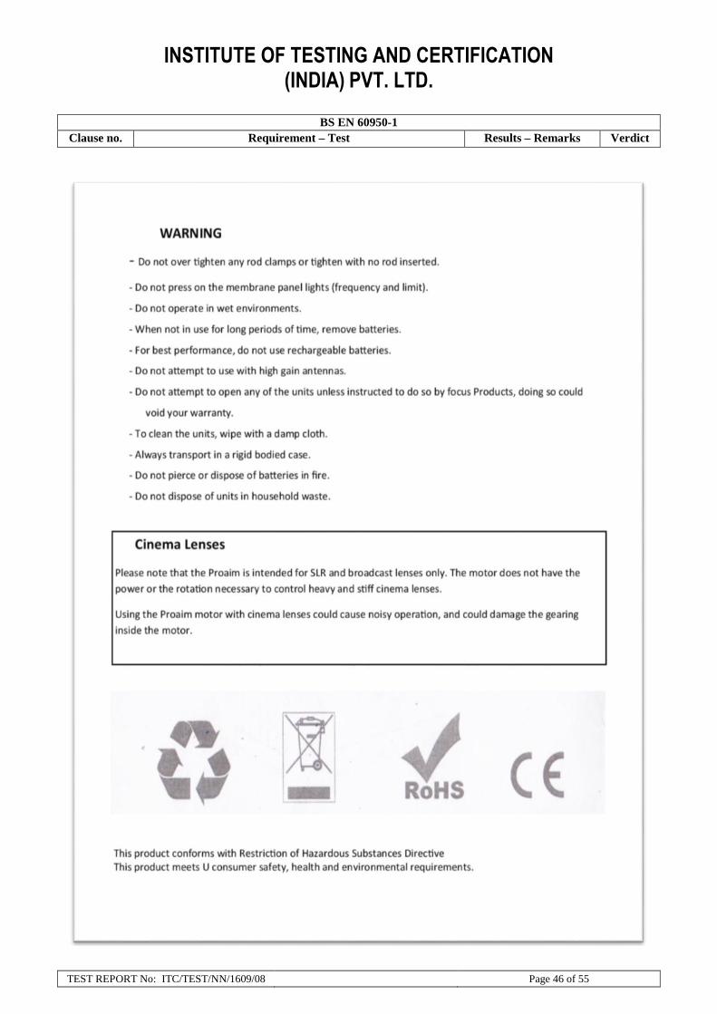
INSTITUTE OF TESTING AND CERTIFICATION (INDIA) PVT. LTD.
BS EN 60950-1
Clause no. Requirement – Test Results – Remarks Verdict
TEST REPORT No: ITC/TEST/NN/1609/08 Page 46 of 55

INSTITUTE OF TESTING AND CERTIFICATION (INDIA) PVT. LTD.
BS EN 60950-1
Clause no. Requirement – Test Results – Remarks Verdict
TEST REPORT No: ITC/TEST/NN/1609/08 Page 47 of 55

INSTITUTE OF TESTING AND CERTIFICATION (INDIA) PVT. LTD.
BS EN 60950-1
Clause no. Requirement – Test Results – Remarks Verdict
TEST REPORT No: ITC/TEST/NN/1609/08 Page 48 of 55

INSTITUTE OF TESTING AND CERTIFICATION (INDIA) PVT. LTD.
BS EN 60950-1
Clause no. Requirement – Test Results – Remarks Verdict
TEST REPORT No: ITC/TEST/NN/1609/08 Page 49 of 55

INSTITUTE OF TESTING AND CERTIFICATION (INDIA) PVT. LTD.
BS EN 60950-1
Clause no. Requirement – Test Results – Remarks Verdict
TEST REPORT No: ITC/TEST/NN/1609/08 Page 50 of 55

INSTITUTE OF TESTING AND CERTIFICATION (INDIA) PVT. LTD.
BS EN 60950-1
Clause no. Requirement – Test Results – Remarks Verdict
TEST REPORT No: ITC/TEST/NN/1609/08 Page 51 of 55

INSTITUTE OF TESTING AND CERTIFICATION (INDIA) PVT. LTD.
BS EN 60950-1
Clause no. Requirement – Test Results – Remarks Verdict
TEST REPORT No: ITC/TEST/NN/1609/08 Page 52 of 55

INSTITUTE OF TESTING AND CERTIFICATION (INDIA) PVT. LTD.
BS EN 60950-1
Clause no. Requirement – Test Results – Remarks Verdict
TEST REPORT No: ITC/TEST/NN/1609/08 Page 53 of 55

INSTITUTE OF TESTING AND CERTIFICATION (INDIA) PVT. LTD.
BS EN 60950-1
Clause no. Requirement – Test Results – Remarks Verdict
TEST REPORT No: ITC/TEST/NN/1609/08 Page 54 of 55

INSTITUTE OF TESTING AND CERTIFICATION (INDIA) PVT. LTD.
BS EN 60950-1
Clause no. Requirement – Test Results – Remarks Verdict
TEST REPORT No: ITC/TEST/NN/1609/08 Page 55 of 55