DRILLING COMMENCES AT THE SILICA HILL GOLD-SILVER ... · 12/5/2016 · Hole CMIPT011, drilled...
12
26 Richardson Street West Perth Western Australia 6005 Tel +61 (8) 6454 6666 Facsimile +61 (8) 6454 6667 Email [email protected] www.impactminerals.com.au ASX ANNOUNCEMENT Date: 5 December 2016 Number: 497/051216 DRILLING COMMENCES AT THE SILICA HILL GOLD-SILVER DISCOVERY NEAR ORANGE IN NSW Follow up drilling has now started at Impact Minerals Limited’s (ASX:IPT) high grade gold-silver discovery at the Silica Hill Prospect, part of the 100%-owned Commonwealth Project 100km north of Orange in New South Wales. The drill programme comprises up to 2,000 metres of reverse circulation and diamond drilling, of which about 500 metres is expected to be completed before Christmas. Significant gold and silver mineralisation has been intersected in four drill holes so far at Silica Hill over an area of 200 metres by 100 metres down to a depth of 100 metres below surface and with an average true thickness of about 50 metres (Figures 1, 2 and 4). The zone strikes north east and dips steeply to the south east. Importantly it appears that grade is increasing with depth (Figures 2 and 3). The mineralisation is open in all directions including up-dip and is terminated by a fault suggesting further mineralisation may have been offset. The drill programme is designed to test for extensions to this mineralisation as well as further depth extensions to the Commonwealth deposit centred about 200 metres south west of Silica Hill (Figure 1). Figure 1. Surface geology map showing significant drill intercepts at Silica Hill and Main Shaft. For personal use only
Transcript of DRILLING COMMENCES AT THE SILICA HILL GOLD-SILVER ... · 12/5/2016 · Hole CMIPT011, drilled...

26 Richardson Street West Perth Western Australia 6005 Tel +61 (8) 6454 6666 Facsimile +61 (8) 6454 6667 Email [email protected] www.impactminerals.com.au
ASX ANNOUNCEMENT Date: 5 December 2016
Number: 497/051216
DRILLING COMMENCES AT THE SILICA HILL GOLD-SILVER
DISCOVERY NEAR ORANGE IN NSW
Follow up drilling has now started at Impact Minerals Limited’s (ASX:IPT) high grade gold-silver
discovery at the Silica Hill Prospect, part of the 100%-owned Commonwealth Project 100km north of
Orange in New South Wales.
The drill programme comprises up to 2,000 metres of reverse circulation and diamond drilling, of which
about 500 metres is expected to be completed before Christmas.
Significant gold and silver mineralisation has been intersected in four drill holes so far at Silica Hill over an
area of 200 metres by 100 metres down to a depth of 100 metres below surface and with an average true
thickness of about 50 metres (Figures 1, 2 and 4). The zone strikes north east and dips steeply to the south
east. Importantly it appears that grade is increasing with depth (Figures 2 and 3).
The mineralisation is open in all directions including up-dip and is terminated by a fault suggesting further
mineralisation may have been offset.
The drill programme is designed to test for extensions to this mineralisation as well as further depth
extensions to the Commonwealth deposit centred about 200 metres south west of Silica Hill (Figure 1).
Figure 1. Surface geology map showing significant drill intercepts at Silica Hill and Main Shaft.
For
per
sona
l use
onl
y

About the Gold-Silver Mineralisation at Silica Hill
The mineralisation comprises disseminated sulphide, veins and semi-massive sulphide veins within the
Silica Hill rhyolite. The veins commonly contain high to very high grades of gold and in particular silver.
For example, Hole CMIPT046 returned 30 individual assays of varying widths of between 2 g/t and
24 g/t gold and 12 individual assays with more than 500 g/t silver (Figure 4) and Hole CMIPT011 returned
two veins with 3,146 g/t silver (0.9 metres thick) and 3,600 g/t silver (0.15 m thick).
The four drill holes that have returned significant intercepts on two sections are: CMIPT046 and
CMIPT026 (Figures 1, 2 and 3) and CMIPT043 and CMIPT011 (Figures 2 and 3).
Drill hole CMIPT046, drilled beneath Hole CMIPT026, returned high grade gold and very high grade
silver over a 41 metre thick intercept within a 74 metre thick zone of gold-silver mineralisation (Figure 4).
Key intercepts include:
74.5 metres at 1.2 g/t gold and 106 g/t silver (2.9 g/t gold equivalent) from 61 metres
including 41.3 metres at 2.0 g/t gold and 176 g/t silver (4.7 g/t gold equivalent) from 61 metres;
which includes 16.3 metres at 3.7 g/t gold and 246 g/t silver (7.6 g/t gold equivalent) from 86 metres.
Gold equivalency calculations are based on the following US dollar prices: Gold $1326/oz; silver and $18.82/oz.
Figure 2. East-West cross section showing results for Holes CMIPT026 and CMIPT046.
For
per
sona
l use
onl
y

Figure 3 shows that the intercept in CMIPT046 includes numerous high grade gold and silver intercepts
from individual veins and groups of veins (which have been sampled in detail) including:
1 metre at 12.2 g/t gold and 680 g/t silver
including 0.3 metres at 23 g/t gold and 1,110 g/t silver;
1 metre at 5.3 g/t gold and 924 g/t silver;
1.7 metres at 3.8 g/t gold and 1,176 g/t silver; and
0.7 metres at 1.5 g/t gold and 855 g/t silver.
Hole CMIPT026, drilled up dip from Hole CMIPT043,
returned 39 metres at 0.3 g/t gold and 16 g/t silver from
5 metres down hole with individual one metre assays up to
1 g/t gold and 32 g/t silver (Figure 2).
This part of the hole comprised RC chips and it is not known if
the significant grade variation between holes CMIPT026 and
CMIPT043 is a primary feature or secondary weathering
(leaching effect).
Figure 3. Detail of gold and silver assays for Hole
CMIPT046. Note that the gold grades have been cut off at
10 g/t, and silver grades are at log scale to allow proper
visualisation of the grades of up to 10 g/t gold and
1,490 g/t silver.
For
per
sona
l use
onl
y
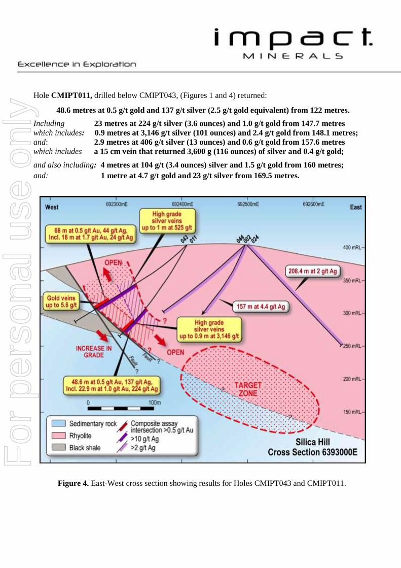
Hole CMIPT011, drilled below CMIPT043, (Figures 1 and 4) returned:
48.6 metres at 0.5 g/t gold and 137 g/t silver (2.5 g/t gold equivalent) from 122 metres.
Including 23 metres at 224 g/t silver (3.6 ounces) and 1.0 g/t gold from 147.7 metres
which includes: 0.9 metres at 3,146 g/t silver (101 ounces) and 2.4 g/t gold from 148.1 metres;
and: 2.9 metres at 406 g/t silver (13 ounces) and 0.6 g/t gold from 157.6 metres
which includes a 15 cm vein that returned 3,600 g (116 ounces) of silver and 0.4 g/t gold;
and also including: 4 metres at 104 g/t (3.4 ounces) silver and 1.5 g/t gold from 160 metres;
and: 1 metre at 4.7 g/t gold and 23 g/t silver from 169.5 metres.
Figure 4. East-West cross section showing results for Holes CMIPT043 and CMIPT011.
For
per
sona
l use
onl
y

Hole CMIPT043, drilled above Hole CMIPT011, (Figures 1 and 4) returned:
68 metres at 0.5 g/t gold and 43 g/t silver (1.3 g/t gold equivalent) from 99 metres;
including the upper silver-rich zone of 37 metres at 0.1 g/t gold and 71 g/t silver (2.3 ounces) and the
lower gold-rich zone of 18 m at 1.7 g/t gold and 24 g/t silver from 149 metres.
Individual results of note in this hole are:
High grade silver intercepts (with gold) in the upper part of the assayed zone:
1 m at 122 g/t (4 ounces) silver and 0.2 g/t gold from 108 metres;
1 m at 146 g/t silver (5 ounces) and 0.1 g/t gold from 118 metres;
2 m at 373 g/t (12 ounces) silver and 0.2 g/t gold from 123 metres including
1 m at 525 g/t (17 ounces) silver and 0.1 g/t gold from 124 metres; and
1 m at 337 g/t (11 ounces) silver and 0.1 g/t gold and from 134 metres.
Significant gold assays in the lower part of zone:
1 m at 2.3 g/t gold and 64 g/t (2 ounces) silver from 153 metres;
and 1 m at 6.4 g/t gold and 18 g/t silver (0.5 ounces) from 155 metres.
In addition it is evident that there is a large silver “halo” of up to 10 to 15 g/t silver in the Silica Hill rhyolite
which extends further outwards over many hundreds of square metres (Figures 1, 2 and 4). It is possible
that this may be a “leakage halo” from depth and accordingly the down-dip extension of the mineralisation
in Holes CMIPT011 and CMIPT046 are compelling drill targets.
Connection between mineralisation at Main Shaft and Silica Hill
The style and nature of mineralisation in Hole CMIPT043 is similar to that encountered in the rhyolite unit
within the Commonwealth deposit and further demonstrates that the mineralisation at the two prospects is
part of one larger system. It is possible that the mineralisation at Silica Hill and Main Shaft may be linked at
depth. Areas where the two styles of mineralisation may connect will be priority target areas.
A gold-silver-in-soil anomaly extends in a NE direction from Main Shaft to Silica Hill and widens in that
direction. This anomaly is open to the north and north-east. This is a further indication that the two areas
may be linked and further drilling at depth is required.
Very high grade silver values of almost 1 kg/tonne over 1 metre were returned in this drill programme from
Hole CMIPT031 at Main Shaft in a 7 metre thick zone of massive sulphide mineralisation that returned:
7 metres at 6.3 g/t gold, 496 g/t silver (15.9 ounces), 7.2% zinc, 2.9% lead and 0.2% copper
(17.7 g/t gold equivalent) from 91 metres
including 3 metres at 10.6 g/t gold, 571 g/t silver (18.4 ounces), 7.8% zinc, 2.1% lead and
0.2% copper (23.0 g/t gold equivalent) from 92 metres and
also including 1 metre at 2.5 g/t gold, 979 g/t silver (31.5 ounces), 8.3% zinc, 4.4% lead and
0.1% copper (21.4 g/t gold equivalent) from 95 metres
This intercept is open down dip, beneath the silver-rich intercepts at Silica Hill (Figure 1).
For
per
sona
l use
onl
y

Dr Michael G Jones
Managing Director
The review of exploration activities and results contained in this report is based on information compiled by Dr Mike Jones, a Member of
the Australian Institute of Geoscientists. He is a director of the company and works for Impact Minerals Limited. He has sufficient
experience which is relevant to the style of mineralisation and types of deposits under consideration and to the activity which he is
undertaking to qualify as a Competent Person as defined in the 2012 edition of the Australasian Code for Reporting of Exploration Results,
Mineral Resources and Ore Reserves (the JORC Code). Dr Jones has consented to the inclusion in the report of the matters based on his
information in the form and context in which it appears.
Impact Minerals confirms that it is not aware of any new information or data that materially affects the information included in the
previous market announcements referred to and in the case of mineral resource estimates, that all material assumptions and technical
parameters underpinning the estimates continue to apply and have not materially changed.
For
per
sona
l use
onl
y

APPENDIX 1 - SECTION 1 SAMPLING TECHNIQUES AND DATA
Criteria JORC Code explanation Commentary
Sampling techniques
Nature and quality of sampling (e.g. cut channels, random chips, or specific specialised industry standard measurement tools appropriate to the minerals under investigation, such as down hole gamma sondes, or handheld XRF instruments, etc). These examples should not be taken as limiting the broad meaning of sampling.
Rock chip samples Random grab samples were taken at surface which represented favourable geology and alteration to known mineralisation in the region. Samples are variably weathered. Soil Samples About 250g of soil was taken from 15-20cm below surface and sieved to - 2mm size. Samples put in plastic snap seal bags. Samples were subsequently sieved to -250 micron at SGS Laboratories for assay by aqua regia digest. RC Drilling Reverse Circulation (RC) percussion drilling was used to produce a 1m bulk sample (~25kg) which was collected in plastic bags and representative 1m split samples (12.5%, or nominally 3kg) were collected using a riffle splitter and placed in a calico bag. The cyclone was cleaned out with compressed air at the end of each hole and periodically during the drilling. Holes were drilled to optimally intercept interpreted mineralised zones. Diamond Drilling Diamond drilling was used to produce drill core either with a diameter of 63.5 mm (HQ) or 47.6 mm (NQ).
Include reference to measures taken to ensure sample representivity and the appropriate calibration of any measurement tools or systems used
Rock chip samples Representative samples at each sample site weigh between 0.8 and 1.2 kg. Sample sites were chosen due to historic rock and soil assay results and the geophysical surveys conducted on the Commonwealth Project. Historic rock sample methods are unknown but are considered immaterial. Soil Samples and Drill Samples Sample representivity was ensured by a combination of Company Procedures regarding quality control (QC) and quality assurance / testing (QA). Examples of QC include (but are not limited to), daily workplace and equipment inspections, as well as drilling and sampling procedures. Examples of QA include (but are not limited to) collection of “field duplicates”, the use of certified standards and blank samples approximately every 50 samples
For
per
sona
l use
onl
y

Criteria JORC Code explanation Commentary
Aspects of the determination of mineralisation that are Material to the Public Report. In cases where ‘industry standard’ work has been done this would be relatively simple (e.g. ‘reverse circulation drilling was used to obtain 1 m samples from which 3 kg was pulverised to produce a 30 g charge for fire assay’). In other cases more explanation may be required, such as where there is coarse gold that has inherent sampling problems. Unusual commodities or mineralisation types (e.g. submarine nodules) may warrant disclosure of detailed information
Rock chip samples Rock samples were sent to SGS Perth where they were crushed, dried and pulverised (total prep) to produce a 25-30 g sub-samples for analysis initially by Aqua Regia digest with ICP-MS finish for base metals then by four acid digest with an ICP/AES finish for ore grade base metal samples and lead collection fire assay with AAS finish for gold. Soil Samples Soil samples were sent to ACME Laboratories in Vancouver for analysis by aqua regia digest or to SGS Laboratories in Perth for analysis by the MMI digest. RC and diamond drill samples RC samples and cut samples of core were submitted to ALS in Orange, NSW. Laboratory sample preparation involved: sample crushed to 70% less than 2mm, riffle/rotary split off 1 kg, pulverise split to >85% passing 75 microns. RC samples analysed by MEICP41 or MEOG46 for ore grade samples, aqua region digest with ICP OES analysis and AA24 fire assay with AAS finish. Historical diamond and RC samples were sent to Fox Anamet, Brookvale NSW where gold was determined by fire assay, base metals by DCP and AAS methods. Weathered samples contained gossanous sulphide material and fresh samples containing visible pyrite, galena, sphalerite and chalcopyrite.
Drilling techniques Drill type (e.g. core, reverse circulation, open-hole hammer, rotary air blast, auger, Bangka, sonic, etc) and details (e.g. core diameter, triple or standard tube, depth of diamond tails, face-sampling bit or other type, whether core is oriented and if so, by what method, etc).
Diamond drilling accounts for about 50 % of the drilling and comprises NQ (47.6 mm diameter) and HQ (63.5 mm diameter) sized core. Impact diamond core is triple tube and is oriented. Historical diamond core was not oriented. RC drilling accounts for about 50% of the drilling and comprises 4 inch hammer.
Drill sample recovery Method of recording and assessing core and chip sample recoveries and results assessed
Diamond core recoveries for all holes are logged and recorded. Recoveries are estimated to be approximately >97% for the Commonwealth Project. No significant core loss or sample recovery problems are observed in the drill core or historic reports. RC samples were visually checked for recovery, moisture and contamination.
Measures taken to maximise sample recovery and ensure representative nature of the samples
Diamond core is reconstructed into continuous runs on an angle iron cradle for orientation marking. Depths are checked against the depth given on the core blocks and rod counts are routinely carried out by the driller. The RC samples are collected by plastic bag directly from the rig-mounted cyclone and laid directly on the ground in rows of 10. The drill cyclone and sample buckets are cleaned between rod-changes and after each hole to minimise down-hole and/or cross contamination.
Whether a relationship exists between sample recovery and grade and whether sample bias may have occurred due to preferential loss/gain of fine/coarse material.
No sample bias has been established.
Logging
Whether core and chip samples have been geologically and geotechnically logged to a level of detail to support appropriate Mineral Resource estimation, mining studies and metallurgical studies.
Geological logging of samples followed company and industry common practice. Qualitative logging of samples included (but not limited to); lithology, mineralogy, alteration, veining and weathering. Diamond core logging included additional fields such as structure and geotechnical parameters. Magnetic Susceptibility measurements were taken for each 1m RC sample and each 1m diamond core interval. For diamond core, information on structure type, dip, dip direction, texture, shape and fill material has been recorded in the logs. RQD data has been recorded on selected diamond holes. Handheld XRF analysis was completed at 50 cm and 1 m intervals on diamond core and for every metre for RC samples.
For
per
sona
l use
onl
y

Criteria JORC Code explanation Commentary
Whether logging is qualitative or quantitative in nature. Core (or costean, channel, etc) photography.
All logging is quantitative, based on visual field estimates. Systematic photography of the diamond core in the wet and dry form was completed. Chip trays with representative 1m RC samples were collected and photographed then stored for future reference.
The total length and percentage of the relevant intersections logged
All diamond drill holes were logged in full. All RC chips samples were geologically logged by Impact’s on-site geologist on a 1m basis, with digital capture in the field. Detailed diamond core logging, with digital capture was conducted for 100% of the core by Impact’s on-site geologist.
Sub-sampling techniques and sample preparation
If core, whether cut or sawn and whether quarter, half or all core taken.
All core samples were sampled by half core. Selected intervals of quarter core will be selected for check assays if required.
If non-core, whether riffled, tube sampled, rotary split, etc and whether sampled wet or dry.
RC samples were split using a riffle splitter.
For all sample types, the nature, quality and appropriateness of the sample preparation technique.
Company procedures were followed to ensure sub-sampling adequacy and consistency. These included (but were not limited to), daily work place inspections of sampling equipment and practices, as well as sub-sample duplicates (“field duplicates”).
Quality control procedures adopted for all sub-sampling stages to maximise representivity of samples.
Laboratory QC procedures for rock sample assays involve the use of internal certified reference material as assay standards, along with blanks, duplicates and replicates. The QC procedure for historical diamond and RC samples is unknown but considered immaterial.
Measures taken to ensure that the sampling is representative of the in situ material collected, including for instance results for field duplicate/second-half sampling.
Sample duplicates from the historical drilling were taken from selected intervals and compared to the original assay. Quarter core was taken for diamond samples and riffle resplits for RC samples.
Whether sample sizes are appropriate to the grain size of the material being sampled.
The samples sizes at Commonwealth are considered appropriate since gold has been identified as predominantly fine-grained by thin section analysis which would indicate the nugget effect is minimal.
Quality of assay data and laboratory tests
The nature, quality and appropriateness of the assaying and laboratory procedures used and whether the technique is considered partial or total.
An industry standard fire assay technique for samples using lead collection with an Atomic Absorption Spectrometry (AAS) finish was used for gold and aqua regia digest for base metals and silver. The quality of historical drill sample assays is unknown, however this is considered immaterial at this stage of exploration.
For geophysical tools, spectrometers, handheld XRF instruments, etc, the parameters used in determining the analysis including instrument make and model, reading times, calibrations factors applied and their derivation, etc.
No geophysical tools were used to determine material element concentrations. A handheld XRF was used for qualitative analysis only.
Nature of quality control procedures adopted (e.g. standards, blanks, duplicates, external laboratory checks) and whether acceptable levels of accuracy (i.e. lack of bias) and precision have been established.
For the rock chips, quality control procedures for assays were followed via internal laboratory protocols. Accuracy and precision are within acceptable limits. The quality control of historical drill sample assays is unknown, however this is considered immaterial at this stage of exploration.
Verification of sampling and assaying
The verification of significant intersections by either independent or alternative company personnel.
Significant intersections from drilling have not been verified by independent or alternative companies. This is not required at this stage of exploration.
For
per
sona
l use
onl
y
Criteria JORC Code explanation Commentary
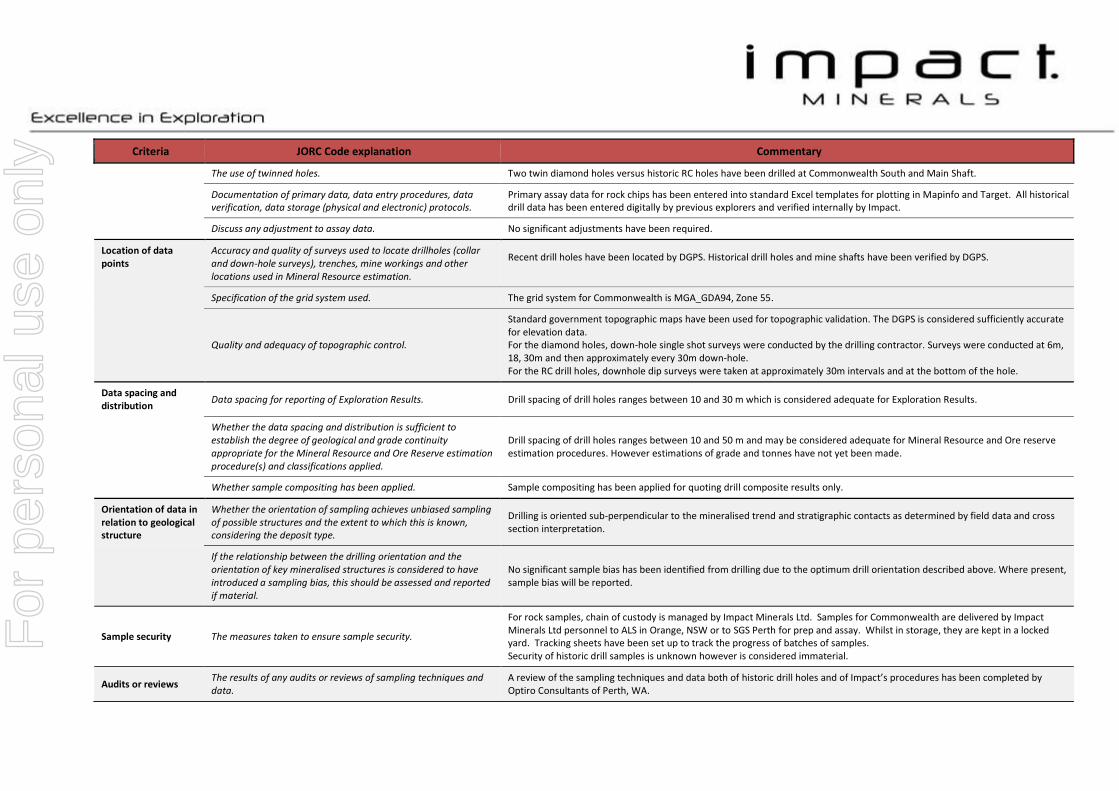
The use of twinned holes. Two twin diamond holes versus historic RC holes have been drilled at Commonwealth South and Main Shaft.
Documentation of primary data, data entry procedures, data verification, data storage (physical and electronic) protocols.
Primary assay data for rock chips has been entered into standard Excel templates for plotting in Mapinfo and Target. All historical drill data has been entered digitally by previous explorers and verified internally by Impact.
Discuss any adjustment to assay data. No significant adjustments have been required.
Location of data points
Accuracy and quality of surveys used to locate drillholes (collar and down-hole surveys), trenches, mine workings and other locations used in Mineral Resource estimation.
Recent drill holes have been located by DGPS. Historical drill holes and mine shafts have been verified by DGPS.
Specification of the grid system used. The grid system for Commonwealth is MGA_GDA94, Zone 55.
Quality and adequacy of topographic control.
Standard government topographic maps have been used for topographic validation. The DGPS is considered sufficiently accurate for elevation data. For the diamond holes, down-hole single shot surveys were conducted by the drilling contractor. Surveys were conducted at 6m, 18, 30m and then approximately every 30m down-hole. For the RC drill holes, downhole dip surveys were taken at approximately 30m intervals and at the bottom of the hole.
Data spacing and distribution
Data spacing for reporting of Exploration Results. Drill spacing of drill holes ranges between 10 and 30 m which is considered adequate for Exploration Results.
Whether the data spacing and distribution is sufficient to establish the degree of geological and grade continuity appropriate for the Mineral Resource and Ore Reserve estimation procedure(s) and classifications applied.
Drill spacing of drill holes ranges between 10 and 50 m and may be considered adequate for Mineral Resource and Ore reserve estimation procedures. However estimations of grade and tonnes have not yet been made.
Whether sample compositing has been applied. Sample compositing has been applied for quoting drill composite results only.
Orientation of data in relation to geological structure
Whether the orientation of sampling achieves unbiased sampling of possible structures and the extent to which this is known, considering the deposit type.
Drilling is oriented sub-perpendicular to the mineralised trend and stratigraphic contacts as determined by field data and cross section interpretation.
If the relationship between the drilling orientation and the orientation of key mineralised structures is considered to have introduced a sampling bias, this should be assessed and reported if material.
No significant sample bias has been identified from drilling due to the optimum drill orientation described above. Where present, sample bias will be reported.
Sample security The measures taken to ensure sample security.
For rock samples, chain of custody is managed by Impact Minerals Ltd. Samples for Commonwealth are delivered by Impact Minerals Ltd personnel to ALS in Orange, NSW or to SGS Perth for prep and assay. Whilst in storage, they are kept in a locked yard. Tracking sheets have been set up to track the progress of batches of samples. Security of historic drill samples is unknown however is considered immaterial.
Audits or reviews The results of any audits or reviews of sampling techniques and data.
A review of the sampling techniques and data both of historic drill holes and of Impact’s procedures has been completed by Optiro Consultants of Perth, WA.
For
per
sona
l use
onl
y

SECTION 2 REPORTING OF EXPLORATION RESULTS
Criteria JORC Code explanation Commentary
Mineral tenement and land tenure status
Type, reference name/number, location and ownership including agreements or material issues with third parties such as joint ventures, partnerships, overriding royalties, native title interests, historical sites, wilderness or national park and environmental settings.
The Commonwealth Project currently comprises 3 exploration licences covering 315 km2. The tenements are held 100% by Endeavour Minerals Pty Ltd, a subsidiary company of Impact Minerals Limited. No aboriginal sites or places have been declared or recorded in areas where Impact is currently exploring. There are no national parks over the license area.
The security of the tenure held at the time of reporting along with any known impediments to obtaining a licence to operate in the area.
The tenements are in good standing with no known impediments.
Exploration done by other parties
Acknowledgment and appraisal of exploration by other parties. A total of 66 drillholes have been completed over 300 m strike between the Commonwealth main shaft and Commonwealth South by previous explorers to an average depth of 53 m.
Geology Deposit type, geological setting and style of mineralisation.
The Commonwealth and Commonwealth South deposits are considered gold-rich volcanic hosted massive sulphide (VMS) deposits that occur at and below the contact with a porphyrictic rhyolite and overlying volcanic sedimentary rocks. The mineralisation may have been overprinted by epithermal mineralisation.
Drill hole Information A summary of all information material to the understanding of the exploration results including a tabulation of the following information for all Material drill holes:
easting and northing of the drill hole collar
elevation or RL (Reduced Level – elevation above sea level in metres) of the drill hole collar
dip and azimuth of the hole
down hole length and interception depth
hole length.
See Table in text.
Data aggregation methods In reporting Exploration Results, weighting averaging techniques, maximum and/or minimum grade truncations (e.g. cutting of high grades) and cut-off grades are usually Material and should be stated.
All reported assays have been length weighted. No top cuts have been applied. A nominal cut-off of approximately 0.5 g/t Au has been applied.
Where aggregate intercepts incorporate short lengths of high grade results and longer lengths of low grade results, the procedure used for such aggregation should be stated and some typical examples of such aggregations should be shown in detail.
High grade massive sulphide intervals internal to broader zones of disseminated sulphide mineralisation are reported as included intervals.
The assumptions used for any reporting of metal equivalent values should be clearly stated.
Gold equivalent values have been used in the long section. Metal prices used for the gold equivalent were $1,650 for gold and $30 for silver. Given the high grade results, it is assumed that very high recoveries will be achieved. However no metallurgical studies have been completed to verify this. Such studies will be done as and when appropriate.
For
per
sona
l use
onl
y

Criteria JORC Code explanation Commentary
Relationship between mineralisation widths and intercept lengths
These relationships are particularly important in the reporting of Exploration Results. If the geometry of the mineralisation with respect to the drill hole angle is known, its nature should be reported. If it is not known and only the down hole lengths are reported, there should be a clear statement to this effect (e.g. ‘down hole length, true width not known’).
Historical drill holes to date have been sub-perpendicular to the mineralised trend and stratigraphy so intervals are close to true width or otherwise stated.
Diagrams Appropriate maps and sections (with scales) and tabulations of intercepts should be included for any significant discovery being reported These should include, but not be limited to a plan view of drill hole collar locations and appropriate sectional views.
Refer to Figures in body of text.
Balanced reporting Where comprehensive reporting of all Exploration Results is not practicable, representative reporting of both low and high grades and/or widths should be practiced to avoid misleading reporting of Exploration Results.
All results reported are representative
Other substantive exploration data
Other exploration data, if meaningful and material, should be reported including (but not limited to): geological observations; geophysical survey results; geochemical survey results; bulk samples – size and method of treatment; metallurgical test results; bulk density, groundwater, geotechnical and rock characteristics; potential deleterious or contaminating substances.
Assessment of other substantive exploration data is not yet complete however considered immaterial at this stage.
Further work The nature and scale of planned further work (e.g. tests for lateral extensions or depth extensions or large-scale step-out drilling). Diagrams clearly highlighting the areas of possible extensions, including the main geological interpretations and future drilling areas, provided this information is not commercially sensitive
Follow up work programmes will be subject to interpretation of recent and historic results which is ongoing.
For
per
sona
l use
onl
y