Drift and Cost Comparison of Different Structural Systems ... · Pak. J. Engg. & Appl. Sci. Vol.12,...
12
Pak. J. Engg. & Appl. Sci. Vol. 12, Jan., 2013 (p. 27-38) 27 Drift and Cost Comparison of Different Structural Systems for Tall Buildings Asif Hameed , Imran Azeem, Asad-ullah Qazi, Burhan Sharif and Noor Muhammad Khan Civil Engineering Department, University of Engineering and Technology Lahore, Pakistan Corresponding Autor :[email protected] , Abstract The race towards new heights and architecture has not been without challenges. Tall structures have continued to climb higher and higher facing strange loading effects and very high loading values due to dominating lateral loads. The design criteria for tall buildings are strength, serviceability, stability and human comfort. But the factors govern the design of tall and slender buildings all the times are serviceability and human comfort against lateral loads. As a result, lateral stiffness is a major consideration in the design of tall buildings. The first parameter that is used to estimate the lateral stiffness of a tall building is drift index. Different lateral load resisting structural subsystems can be used to impart stiffness and reduce drift in the building. Lateral load resisting subsystems can take many forms depending upon the orientation, integration and addition of the various structural components. In this research, sixteen different lateral load resisting structural subsystems are used to design a tall building and finally the most economical structural system is selected amongst these. For this purpose a hundred and five storey square shaped prismatic steel building uniform through the height is selected, analyzed and designed for gravity and wind loads. Analysis and design of selected lateral load resisting structural subsystems reveals that, for the building configuration selected, the structural system containing composite super columns with portals subsystem is most efficient. Key Words: Tall Buildings, Lateral load resisting subsystems, Drift index, Cost effectiveness 1. Introduction Humans have always admired tall structures since ancient times for visibility, their individual social status, highest respect of their societies and subjects of legends. Now a days high cost of land in developed cities of the world, need to cluster population at or near commercial hubs and need to maintain agricultural production have forced the structures to expand in vertical direction. Moreover new achievements in material science, computer- aided design and construction technology have also attracted architects towards more sophisticated, elegant, state of the art non traditional architectural and structural systems for tall structures. Tallness is a relative term. A quantitative definition of tall buildings cannot be applied universally. From structural engineering viewpoint, a tall building may be defined as the one whose structural design is dominated by the lateral forces [1]. The race towards the new heights has not been without challenges. Usually increase in height is combined with unintended increase in flexibility. Possible lack of stiffness or damping adds vulnerability to the structures against lateral loads [2]. The design criteria for tall buildings are strength, serviceability, stability and human comfort. But the factors govern the design of tall and slender buildings all the times are the human comfort and maximum column free space. When a tall building is subjected to lateral loads, the resulting oscillatory movement induces a wide range of responses in the building and its occupants. As far as the ultimate limit state is concerned, lateral deflections must be limited to prevent second-order P-Δ effects due to gravity loading being of such a magnitude as to precipitate collapse. In terms of serviceability limit states, deflections must be maintained at a sufficient low level to allow proper functioning of nonstructural components and to avoid distress in the structure to prevent excessive cracking and consequent loss of stiffness and to avoid any redistribution of the loads to non structural components. Considering human comfort level, the structure must be sufficiently stiff to prevent dynamic motions becoming large enough to cause discomfort to occupants. As a result, lateral deflection and lateral stiffness are major considerations in the design of tall buildings. Design of structural systems for steel buildings is one of the most complex design problems in development of tall buildings [3].
Transcript of Drift and Cost Comparison of Different Structural Systems ... · Pak. J. Engg. & Appl. Sci. Vol.12,...
Pak. J. Engg. & Appl. Sci. Vol. 12, Jan., 2013 (p. 27-38)
27
Drift and Cost Comparison of Different Structural Systems for Tall
Buildings
Asif Hameed, Imran Azeem, Asad-ullah Qazi, Burhan Sharif and Noor Muhammad Khan
Civil Engineering Department, University of Engineering and Technology Lahore, Pakistan
Corresponding Autor :[email protected],
Abstract
The race towards new heights and architecture has not been without challenges. Tall structures have continued to climb higher and higher facing strange loading effects and very high loading values
due to dominating lateral loads. The design criteria for tall buildings are strength, serviceability, stability and human comfort. But the factors govern the design of tall and slender buildings all the times are serviceability and human comfort against lateral loads. As a result, lateral stiffness is a
major consideration in the design of tall buildings. The first parameter that is used to estimate the lateral stiffness of a tall building is drift index. Different lateral load resisting structural subsystems can be used to impart stiffness and reduce drift in the building. Lateral load resisting subsystems can
take many forms depending upon the orientation, integration and addition of the various structural
components. In this research, sixteen different lateral load resisting structural subsystems are used to design a tall building and finally the most economical structural system is selected amongst these. For this purpose a hundred and five storey square shaped prismatic steel building uniform through the
height is selected, analyzed and designed for gravity and wind loads. Analysis and design of selected lateral load resisting structural subsystems reveals that, for the building configuration selected, the structural system containing composite super columns with portals subsystem is most efficient.
Key Words: Tall Buildings, Lateral load resisting subsystems, Drift index, Cost effectiveness
1. Introduction Humans have always admired tall structures
since ancient times for visibility, their individual
social status, highest respect of their societies and
subjects of legends. Now a days high cost of land in
developed cities of the world, need to cluster
population at or near commercial hubs and need to
maintain agricultural production have forced the
structures to expand in vertical direction. Moreover
new achievements in material science, computer-
aided design and construction technology have also
attracted architects towards more sophisticated,
elegant, state of the art non traditional architectural
and structural systems for tall structures.
Tallness is a relative term. A quantitative
definition of tall buildings cannot be applied
universally. From structural engineering viewpoint, a
tall building may be defined as the one whose
structural design is dominated by the lateral forces
[1]. The race towards the new heights has not been
without challenges. Usually increase in height is
combined with unintended increase in flexibility.
Possible lack of stiffness or damping adds
vulnerability to the structures against lateral loads
[2].
The design criteria for tall buildings are strength,
serviceability, stability and human comfort. But the
factors govern the design of tall and slender buildings
all the times are the human comfort and maximum
column free space. When a tall building is subjected
to lateral loads, the resulting oscillatory movement
induces a wide range of responses in the building and
its occupants. As far as the ultimate limit state is
concerned, lateral deflections must be limited to
prevent second-order P-Δ effects due to gravity
loading being of such a magnitude as to precipitate
collapse. In terms of serviceability limit states,
deflections must be maintained at a sufficient low
level to allow proper functioning of nonstructural
components and to avoid distress in the structure to
prevent excessive cracking and consequent loss of
stiffness and to avoid any redistribution of the loads
to non structural components. Considering human
comfort level, the structure must be sufficiently stiff
to prevent dynamic motions becoming large enough
to cause discomfort to occupants. As a result, lateral
deflection and lateral stiffness are major
considerations in the design of tall buildings. Design
of structural systems for steel buildings is one of the
most complex design problems in development of tall
buildings [3].

Pak. J. Engg. & Appl. Sci. Vol.12, Jan., 2013
28
Selection of structural system for tall buildings
depends upon shape, horizontal and vertical aspect
ratios, nature and magnitude of lateral loads, internal
planning of the building, availability of material of
construction, facade treatment and location and
routing of the HVAC (heating, ventilation, and air
conditioning) system [1]. The selected structural
system should be strong enough to withstand
anticipated loads without failure, stiff enough to keep
lateral deflections and lateral load induced motions
within limits with minimum cost [4]. Every structural
system has a wide range of height applications
depending upon design concept and criteria. For each
set of design concept and criteria, there is always an
optimum structural system [5].
The first parameter that is used to estimate the
lateral stiffness of tall building is drift index. Drift
Index is the ratio of the maximum lateral deflections
at the top of the building to the total height of super
structure.
The efficiency of the structural system is roughly
compared in terms of cost of structural system per
unit area of the building. So major parameter of
interest in final selection of structural system is the
structural mass per unit area of building. An ideal
situation is the one when steel required to carry the
gravity loads alone could carry the lateral loads. But
in tall buildings it is not possible and compensation
for lateral loads is always required [6].
The objective of this research is to find out the
most efficient, economical and viable structural
scheme that satisfies design criteria and remain
integrated with the architectural design. In this
research, various structural systems for tall buildings
have been studied and analyzed. Topic of research is
broad and wide. Each structural system is a complete
subject in itself and normally in actual design; a
combination of different structural systems is adopted
for most economical and optimal solution.
Considering each system individually and then in
combination and for variety of heights is beyond
scope of this research. So work is limited to a cost
comparison (in terms of mass of steel) of individual
structural systems for a square shaped prismatic steel
building, uniform throughout the height and
subjected to gravity and wind loads only.
To compare different structural systems for drift,
a square shaped prismatic steel building uniform
throughout the height is selected. The building
adopted for the research has following configuration.
Length of building (L) =54.86 m (180 ft)
Width of building (B) =54.86 m (180 ft)
Roof level = 386 m (1266 ft)
Height of spire= Spire not considered
Total height of building (H) = 386 m (1266 ft)
Floor height = 3.65 m (12 ft) Typ.
No. of stories = 105
Horizontal aspect ratio (L/B) = 1
Vertical aspect ratio (H/L, H/B) = 7
Floor area (A) = 3010.7 m2 (32400 sqft
2)
Service core area (A’) = 655.8 m2 (7056 ft
2)
2. Structural System Configurations
A total of 16 structural systems are considered
for comparison purpose which have been developed
and employed with success all around the world [1].
They are described in Table 1.
Table 1: Structural Systems Configurations
2.1 Ordinary Moment Frame
This configuration consists of an
assembly of vertical columns and horizontal
beams distributed throughout the plan and
joined by moment connections. Panel
dimensions are 7.31m x 7.31m and 6.4m x
7.31m. Service core substructure consists of
a framed tube with column spacing of 3.2m.
Floor beams are rigidly connected with core
structural subsystem and contribute in
lateral load resistance. Depth of internal
beams is restricted up to 685mm for
clearance requirements.
Service Core
L0
Plan Elevation
Ordinary Moment Frame
[email protected]@6.40m [email protected] [email protected]@6.4m

Drift and Cost Comparison of Different Structural Systems for Tall Buildings
29
2.2 Braced Moment Frame Configuration
This configuration consists of an
assembly of vertical columns and horizontal
beams distributed throughout the plan and
joined by moment connections. Diagonal
bracing members affective only in tension
are provided in the exterior panels. Panel
dimensions are 7.31m x 7.31m and 6.4m x
7.31m. Service core substructure consists of
a framed tube with column spacing of 3.2m.
Floor beams are rigidly connected with core
structural subsystem and contribute in
lateral load resistance. Depth of internal
beams is restricted up to 685mm for
clearance requirements.
L0
[email protected]@6.4m [email protected] [email protected]@6.4m
Service Core
Plan Elevation
2.3 Framed Tube (Closely Spaced) Configuration
This configuration consists of an
assembly of closely spaced vertical columns
and deep spandrels joined by moment
connections. These columns and spandrels
are aligned at perimeter of the building.
Column spacing at perimeter is 3.66m from
first to fourth floor and 1.83m above.
Service core substructure consists of a
framed tube with column spacing of 3.66m.
L0
Plan at 18.3m
Framed Tube (closely spaced)
Service Core
Elevation
2.4 Framed Tube (Widely Spaced) Configuration
This configuration consists of an
assembly of vertical columns and deep
spandrels joined by moment connections.
These columns and spandrels are aligned at
perimeter of the building. Column spacing
at perimeter is 3.66 m and is uniform
through the height. Service core
substructure consists of a framed tube with
column spacing of 3.66 m.
L0
Service Core
Plan Elevation
Pak. J. Engg. & Appl. Sci. Vol.12, Jan., 2013
30
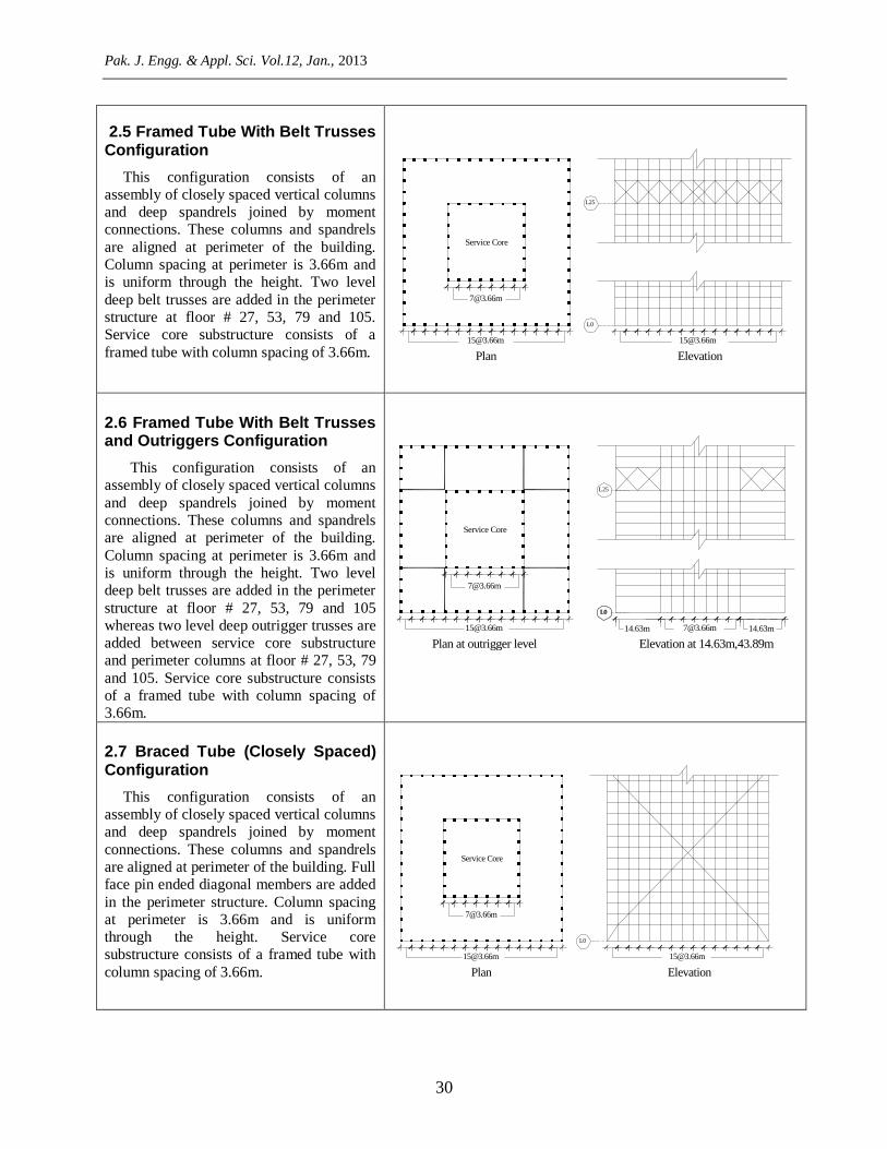
2.5 Framed Tube With Belt Trusses Configuration
This configuration consists of an
assembly of closely spaced vertical columns
and deep spandrels joined by moment
connections. These columns and spandrels
are aligned at perimeter of the building.
Column spacing at perimeter is 3.66m and
is uniform through the height. Two level
deep belt trusses are added in the perimeter
structure at floor # 27, 53, 79 and 105.
Service core substructure consists of a
framed tube with column spacing of 3.66m.
L25
L0
[email protected] [email protected]
Service Core
Plan Elevation
2.6 Framed Tube With Belt Trusses and Outriggers Configuration
This configuration consists of an
assembly of closely spaced vertical columns
and deep spandrels joined by moment
connections. These columns and spandrels
are aligned at perimeter of the building.
Column spacing at perimeter is 3.66m and
is uniform through the height. Two level
deep belt trusses are added in the perimeter
structure at floor # 27, 53, 79 and 105
whereas two level deep outrigger trusses are
added between service core substructure
and perimeter columns at floor # 27, 53, 79
and 105. Service core substructure consists
of a framed tube with column spacing of
3.66m.
L0
L25
L0
[email protected] 14.63m
Elevation at 14.63m,43.89m
Service Core
Plan at outrigger level
2.7 Braced Tube (Closely Spaced) Configuration
This configuration consists of an
assembly of closely spaced vertical columns
and deep spandrels joined by moment
connections. These columns and spandrels
are aligned at perimeter of the building. Full
face pin ended diagonal members are added
in the perimeter structure. Column spacing
at perimeter is 3.66m and is uniform
through the height. Service core
substructure consists of a framed tube with
column spacing of 3.66m.
L0
Service Core
Plan Elevation

Drift and Cost Comparison of Different Structural Systems for Tall Buildings
31
2.8 Braced Tube (Widely Spaced) Configuration
This configuration consists of an
assembly of vertical columns and deep
spandrels joined by moment connections.
These columns and spandrels are aligned at
perimeter of the building. Full face pin
ended diagonal members are added in the
perimeter structure. Column spacing at
perimeter is 3.66m and 7.32m. Service core
substructure consists of a framed tube with
column spacing of 3.66m.
L0
3.66m [email protected] 3.66m [email protected] 3.66m 3.66m [email protected] 3.66m [email protected] 3.66m
Service Core
Plan Elevation
2.9 Bundled Tube Configuration
It is a modified form of framed tube
subsystem in which additional lines of rigid
frames, similar in configuration with outer
tube, are introduced orthogonally inside the
tube. This addition results in formation of a
bundle of individual tubes connected and
acting together. It consists of an assembly
of multiple framed tubes joined together to
form a bundle. Column spacing of framed
tubes is 3.66m. Service core substructure is
formed by the sides of adjoining framed
tubes.
L0
Tube 2Tube 1 Tube 3
Tube 4 Tube 5
Tube 7Tube 6 Tube 8
Service Core
Plan Elevation
2.10 Exoskeleton Configuration
It consists of independent vertical load
resisting subsystems and lateral load
resisting subsystems. Lateral load resisting
subsystem is located out side the building
lines away from facade. Any basic form of
lateral load resisting subsystem can be
selected as exoskeleton This configuration
consists of independent vertical and lateral
load resisting subsystems. Lateral load
resisting subsystems is oriented outside the
perimeter of the building as a braced tube
with column spacing of 3.66m and 7.32m.
L0
3.66m [email protected] 3.66m [email protected] 3.66m3.66m [email protected] 3.66m [email protected] 3.66m
Service Core
Plan Elevation

Pak. J. Engg. & Appl. Sci. Vol.12, Jan., 2013
32
2.11 Lattice Tube Configuration
This configuration consists of an
assembly of vertical columns and pin ended
diagonal members aligned at perimeter of
the building. Spandrel beams are eliminated
from the perimeter structure. Column
spacing at perimeter is 3.66m and is
uniform through the height. For clearance
requirements, diagonal members are
eliminated from central seven bays of
ground floor. Service core substructure
consists of a framed tube with column
spacing of 3.66m.
L0
Service Core
Plan at 9.14m Elevation
2.12 Diagrid Configuration
It is another modified form of tube
subsystem concept. It consists of an
assembly of inclined/diagonal members and
horizontal spandrels without conventional
vertical columns. Inclined/diagonal
members are designed to carry all the loads.
In this research this system consists of an
assembly of inclined columns and spandrel
beams aligned at perimeter of the building.
Vertical columns other than corner columns
are eliminated from perimeter structure.
Column spacing at perimeter is 9.14m at an
inclination of 77o. Service core substructure
consists of a framed tube with column
spacing of 3.66m.
L0
4.57m
4.57m
Service Core
Plan at 20.12m Elevation
2.13 Mega Frame Configuration
It consists of stiff planer assemblies
concentrated near corners of the building
and connected through horizontal elements/
multistory trusses at intervals. These
interconnected assemblies take the form of a
portal frame. This portal frame resists
lateral loads as an exterior structure. Here
this configuration consists of an assembly
of groups of vertical columns, spandrel
beams and diagonal members aligned at
perimeter, near corners of the building.
These groups are joined together with three
level deep portals/belt trusses at every 15th
floor. Column spacing at perimeter is
3.66m. Service core substructure consists of
a framed tube with column spacing of
3.66m.
L15
L0
Service Core
Plan Elevation

Drift and Cost Comparison of Different Structural Systems for Tall Buildings
33
2.14 Steel Super Columns With Portals Configuration
Columns with portal configuration consist
of three or more massive columns located at appropriate locations and joined together
through portals or braces. Philosophy behind
locating super/mega columns at extremities is
concentration of resistance at maximum
available distance to get maximum resistive
couple and inertia with economy. Steel super
columns with portals configuration consists of
an assembly of four vertical steel super
columns located at corners of the building.
These columns are joined together with three
level deep trusses/portals at every 4th floor. Service core substructure consists of a framed
tube with column spacing of 3.66m.
L0
54.87m54.87m
Service Core
Plan Elevation
2.15 Composite Steel Super Columns With Bracing Configuration
Composite steel super columns with
bracing configuration consist of an
assembly of four vertical composite steel
filled super columns located at corners of
the building. These columns are joined
together with three level deep
trusses/portals at every 15th floor and
diagonal bracing members effective only in
tension. Hangers at a distance of 3.66m are
provided from trusses/portals to support
floor system. Service core substructure
consists of a framed tube with column
spacing of 3.66m.
L15
L0
54.87m54.87m
Service Core
Plan Elevation
2.16 Composite Steel Super Columns With Portals Configuration
Composite steel super columns with
portals configuration consists of an
assembly of four vertical composite steel
filled super columns located at corners of
the building. These columns are joined
together with three level deep
trusses/portals at every 4th floor. Service
core substructure consists of a framed tube
with column spacing of 3.66m.
L0
54.87m54.87m
Service Core
Plan Elevation
Pak. J. Engg. & Appl. Sci. Vol.12, Jan., 2013
34
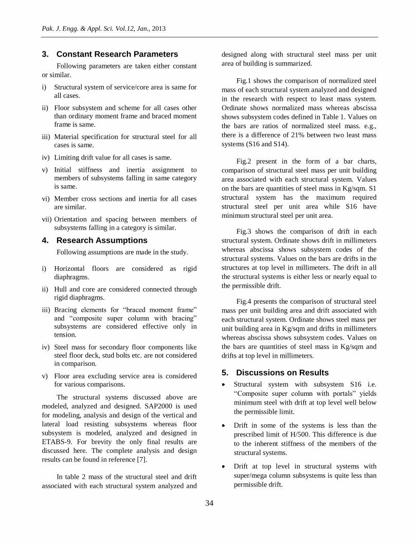
3. Constant Research Parameters
Following parameters are taken either constant
or similar.
i) Structural system of service/core area is same for
all cases.
ii) Floor subsystem and scheme for all cases other
than ordinary moment frame and braced moment
frame is same.
iii) Material specification for structural steel for all
cases is same.
iv) Limiting drift value for all cases is same.
v) Initial stiffness and inertia assignment to
members of subsystems falling in same category
is same.
vi) Member cross sections and inertia for all cases
are similar.
vii) Orientation and spacing between members of
subsystems falling in a category is similar.
4. Research Assumptions
Following assumptions are made in the study.
i) Horizontal floors are considered as rigid
diaphragms.
ii) Hull and core are considered connected through
rigid diaphragms.
iii) Bracing elements for “braced moment frame”
and “composite super column with bracing”
subsystems are considered effective only in
tension.
iv) Steel mass for secondary floor components like
steel floor deck, stud bolts etc. are not considered
in comparison.
v) Floor area excluding service area is considered
for various comparisons.
The structural systems discussed above are
modeled, analyzed and designed. SAP2000 is used
for modeling, analysis and design of the vertical and
lateral load resisting subsystems whereas floor
subsystem is modeled, analyzed and designed in
ETABS-9. For brevity the only final results are
discussed here. The complete analysis and design
results can be found in reference [7].
In table 2 mass of the structural steel and drift
associated with each structural system analyzed and
designed along with structural steel mass per unit
area of building is summarized.
Fig.1 shows the comparison of normalized steel
mass of each structural system analyzed and designed
in the research with respect to least mass system.
Ordinate shows normalized mass whereas abscissa
shows subsystem codes defined in Table 1. Values on
the bars are ratios of normalized steel mass. e.g.,
there is a difference of 21% between two least mass
systems (S16 and S14).
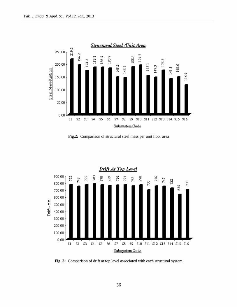
Fig.2 present in the form of a bar charts,
comparison of structural steel mass per unit building
area associated with each structural system. Values
on the bars are quantities of steel mass in Kg/sqm. S1
structural system has the maximum required
structural steel per unit area while S16 have
minimum structural steel per unit area.
Fig.3 shows the comparison of drift in each
structural system. Ordinate shows drift in millimeters
whereas abscissa shows subsystem codes of the
structural systems. Values on the bars are drifts in the
structures at top level in millimeters. The drift in all
the structural systems is either less or nearly equal to
the permissible drift.
Fig.4 presents the comparison of structural steel
mass per unit building area and drift associated with
each structural system. Ordinate shows steel mass per
unit building area in Kg/sqm and drifts in millimeters
whereas abscissa shows subsystem codes. Values on
the bars are quantities of steel mass in Kg/sqm and
drifts at top level in millimeters.
5. Discussions on Results
Structural system with subsystem S16 i.e.
“Composite super column with portals” yields
minimum steel with drift at top level well below
the permissible limit.
Drift in some of the systems is less than the
prescribed limit of H/500. This difference is due
to the inherent stiffness of the members of the
structural systems.
Drift at top level in structural systems with
super/mega column subsystems is quite less than
permissible drift.

Drift and Cost Comparison of Different Structural Systems for Tall Buildings
35
Table 2 Subsystems, total structural steel mass in each system, structural steel mass per unit area of building and
corresponding drift.
Subsystem
Code Subsystem
Total
Structural
Steel
Structural Steel
per Unit Area Drift
x103 Kg (Kg/sqm) (mm)
S1 Ordinary moment frame 54,208 219.15 772
S2 Braced moment frame 48,537 196.23 748
S3 Framed tube (Closely spaced) 43,079 174.16 772
S4 Framed tube (Widely spaced) 46,211 186.82 783
S5 Framed tube (Widely spaced) with
belt trusses 46128 186.49 770
S6 Framed tube (Widely spaced) with
outriggers and belt trusses 45429 183.66 759
S7 Braced tube (Closely spaced) 36681 148.30 766
S8 Braced tube (Widely spaced) 36037 145.69 771
S9 Bundled tube 46598 188.39 753
S10 Exoskeleton 48148 194.65 770
S11 Lattice tube 37873 153.12 700
S12 Diagrid 36442 147.33 756
S13 Mega frame 43348 175.25 747
S14 Steel super column with portals 34897 141.08 722
S15 Composite super column with
bracing 36758 148.61 635
S16 Composite super column with portals 28926 116.94 703
Fig.1: Normalized mass w.r.t least mass structure
Pak. J. Engg. & Appl. Sci. Vol.12, Jan., 2013
36
Fig.2: Comparison of structural steel mass per unit floor area
Fig. 3: Comparison of drift at top level associated with each structural system

Drift and Cost Comparison of Different Structural Systems for Tall Buildings
37
Fig. 4: Structural steel mass per unit area in ascending order and corresponding drift at top level
Both least mass structural systems (S16 and S14)
are quite efficient in terms of drift. Least mass
structural system is also efficient than the second
least mass system, in terms of drift.
There is a difference of 21% between steel
masses of first and second least mass systems
(S16 and S14). On the other hand difference in
maximum drift of both the systems is 2.7% in
same sense which if equalized will result in an
increase in difference of steel masses.
There is a difference of 3.2% between steel
masses of second and third least mass systems.
On the other hand difference in maximum drift of
both the systems is 6.8% in same sense which if
equalized will result in an increase in difference
of steel masses.
There is a difference of 27% between steel
masses of structural systems with subsystem S15
and S16. On the other hand difference in
maximum drift of both the systems is 10.6% in
opposite sense which if equalized will result in
reduction in difference of steel masses.
The drift in all the structural systems is either
less or nearly equal to the permissible drift.
6. Conclusions
On the basis of results of the analysis and design
the following conclusions are drawn:
1. For the building configuration selected, structural
system “Composite Super Columns with Portals”
subsystem is most efficient.
2. Structural system with “Ordinary Moment
Frame” is least economical in terms of structural
steel mass.
3. Structural system with subsystem “ Closely
Spaced Frame Tube” is more economical than
“Widely Spaced Framed Tube”
4. Structural systems containing super columns at
appropriate locations are most economical and
efficient for extremely tall and slender buildings.
5. Composite super columns with portals, super
columns with portals and braced tube widely
spaced are recommended as they can result in
most efficient and economical structures.
Pak. J. Engg. & Appl. Sci. Vol.12, Jan., 2013
38
6 References
[1] Smith, B.S. and Coull, A. (1991). Tall Building
Structures: Analysis and Design. John Wiley
and Sons, Inc., New York.
[2] Gerasimidis, S. Efthymiou, E. & Baniotopoulos,
C. C. (2009). “Optimum Outrigger Locations of
High-rise Steel Buildings for Wind Loading.”
EACWE 5 Florence, Italy.
[3] Kicinger, R. (2006). “Evolutionary
Developmental System for Structural Design.”
Developmental Systems Papers from the AAAI
Fall Symposium. Technical Report FS-06-03,
The American Association for Artificial
Intelligence, Menlo Park, CA, 1-8
[4] Kareem, A. Kijewski, T. Tamura, Y. (1999).
Mitigation of Motions of Tall Buildings with
Specific Example of Recent Applications. Wind
and Structures, Vol. 2, No. 3 pp 201-251
[5] Mir, M.A. and Moon. K.S. (2007). Structural
Development in Tall Buildings: Current Trends
and Future Prospects. Architectural Science
Review Vol. 50.3, pp 205-223
[6] Jayachandran, P. (2009). “Design of Tall
Buildings. Preliminary Design and
Optimization.” Proceedings, National
Workshop on High-rise and Tall Buildings,
University of Hyderabad. Hyderabad, India.
[7] Azeem, I. (2011) Drift Comparison of Different
Structural Systems for Tall Buildings. M.Sc.
thesis Department of Civil Engineering, UET,
Lahore.
[8] ASCE 7-05 (2006). “Minimum Design Loads
for Buildings and Other Structures.” American
Society of Civil Engineers, Virginia 20191.
[9] Choi, H.S. (2009). “Super Tall Building
Design Approach.” Proceedings of The
American Institute of Architects Continuing
Education Systems Program.
[10] Kowalczyk, R.M. Sinn, R. Kilmister, M.B.
(1995). Structural Systems for Tall Buildings.
McGraw-Hill, Inc., New York.