Dresser Intervention Technologies for Energy Pipeline … fittings are welded in accordance with...
20
GE Oil & Gas Dresser * Intervention Technologies for Energy Pipeline Systems
Transcript of Dresser Intervention Technologies for Energy Pipeline … fittings are welded in accordance with...

GE Oil & Gas
Dresser* Intervention Technologies for Energy Pipeline Systems

2
Content
Distribution ProductsLS-2 Fittings Class 150 - Max. 285 psi @ 100°FWeld Fittings ......................................... Page 4
Reduced Branch Weld Fittings .......... Page 5
Spherical Fittings ................................ Page 5
Reduced Branch Spherical Fittings .. Page 5
Class 300 - Max. 740 psi @ 100°FSplit Sleeve Fittings ............................. Page 6
Split Sleeve Fittings w/Side Outlet ........................................ Page 6
Spherical Fittings ................................. Page 6
LS-2 Completion Plugs and Spare O-Rings ............................... Page 7
Style 50 Mechanical Split Sleeves with LS-2 Branch Options .................. Page 7
Transmission Products Line Stop Fittings Class 150 - Max. 285 psi @ 100°F Class 300 - Max. 740 psi @ 100°F Class 600 - Max. 1480 psi @ 100°FSplit Sleeve Line Stop Fittings ............ Page 8
Line Stop Fittings w/Side Outlets ...... Page 9
Line Stop Reducing Branch Fittings . Page 9
Line Stop Spherical Fittings ............. Page 10
Line Stop Flanges ............................... Page 10
Line Stop Completion Plugs ............. Page 11
Purge & Equalization Fittings ......... Page 11
Accessories
PIG Signals .......................................... Page 11
Shell Cutters & Pilot Drills .......... Page 12-13
Sealing Cups ....................................... Page 14
Hot Tapping Machines ...................... Page 15
Line Stop Plugging Equipment ............ 16-17
3
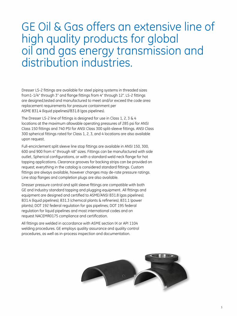
Dresser LS-2 fittings are available for steel piping systems in threaded sizes from1-1/4” through 3” and flange fittings from 4” through 12”. LS-2 fittings are designed,tested and manufactured to meet and/or exceed the code area replacement requirements for pressure containment per ASME B31.4 (liquid pipelines)/B31.8 (gas pipelines).
The Dresser LS-2 line of fittings is designed for use in Class 1, 2, 3 & 4 locations at the maximum allowable operating pressures of 285 psi for ANSI Class 150 fittings and 740 PSI for ANSI Class 300 split-sleeve fittings. ANSI Class 300 spherical fittings rated for Class 1, 2, 3, and 4 locations are also available upon request.
Full-encirclement split sleeve line stop fittings are available in ANSI 150, 300, 600 and 900 from 4” through 48” sizes. Fittings can be manufactured with side outlet, Spherical configurations, or with a standard weld neck flange for hot tapping applications. Clearance grooves for backing strips can be provided on request; everything in the catalog is considered standard fittings. Custom fittings are always available, however changes may de-rate pressure ratings. Line stop flanges and completion plugs are also available.
Dresser pressure control and split sleeve fittings are compatible with both GE and Industry standard tapping and plugging equipment. All fittings and equipment are designed and certified to ASME/ANSI B31.8 (gas pipelines); B31.4 (liquid pipelines); B31.3 (chemical plants & refineries); B31.1 (power plants); DOT 192 federal regulation for gas pipelines; DOT 195 federal regulation for liquid pipelines and most international codes and on request NACEMR0175 compliance and certification.
All fittings are welded in accordance with ASME section IX or API 1104 welding procedures. GE employs quality assurance and quality control procedures, as well as in-process inspection and documentation.
GE Oil & Gas offers an extensive line of high quality products for global oil and gas energy transmission and distribution industries.
4
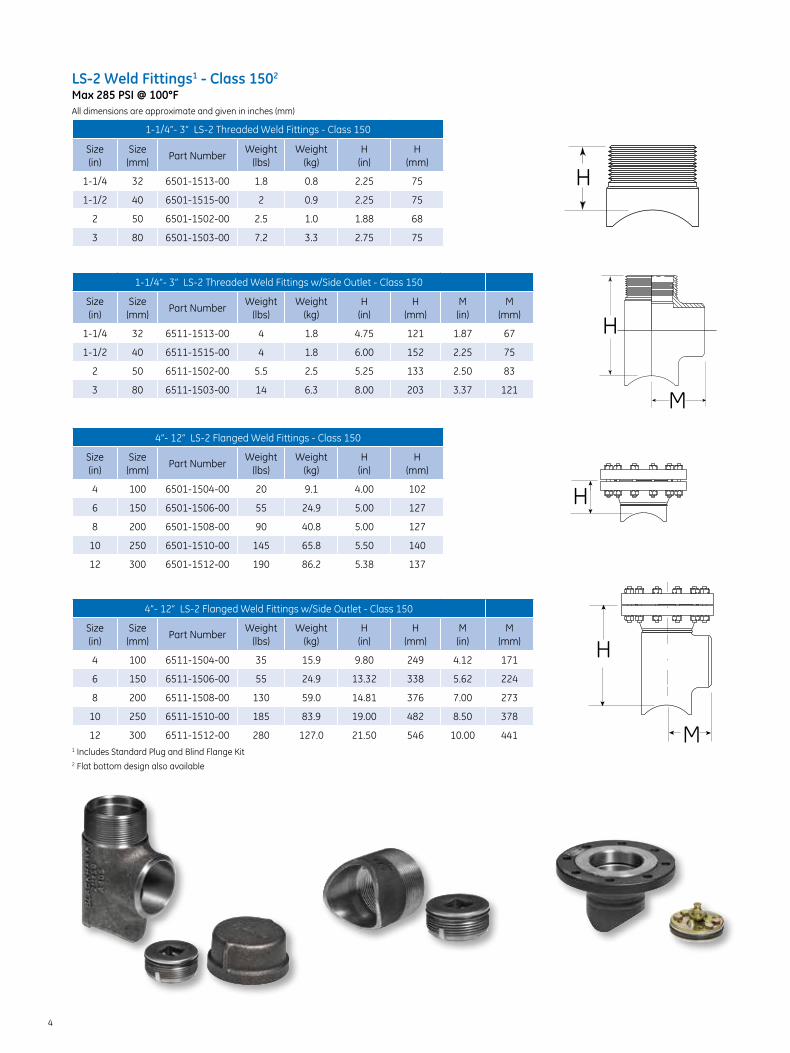
LS-2 Weld Fittings1 - Class 1502 Max 285 PSI @ 100°F All dimensions are approximate and given in inches (mm)
1-1/4”- 3” LS-2 Threaded Weld Fittings - Class 150
Size (in)
Size (mm)
Part NumberWeight
(lbs)Weight
(kg)H
(in)H
(mm)
1-1/4 32 6501-1513-00 1.8 0.8 2.25 75
1-1/2 40 6501-1515-00 2 0.9 2.25 75
2 50 6501-1502-00 2.5 1.0 1.88 68
3 80 6501-1503-00 7.2 3.3 2.75 75
1-1/4”- 3” LS-2 Threaded Weld Fittings w/Side Outlet - Class 150
Size (in)
Size (mm)
Part NumberWeight
(lbs)Weight
(kg)H
(in)H
(mm)M (in)
M (mm)
1-1/4 32 6511-1513-00 4 1.8 4.75 121 1.87 67
1-1/2 40 6511-1515-00 4 1.8 6.00 152 2.25 75
2 50 6511-1502-00 5.5 2.5 5.25 133 2.50 83
3 80 6511-1503-00 14 6.3 8.00 203 3.37 121
4”- 12” LS-2 Flanged Weld Fittings - Class 150
Size (in)
Size (mm)
Part NumberWeight
(lbs)Weight
(kg)H
(in)H
(mm)
4 100 6501-1504-00 20 9.1 4.00 102
6 150 6501-1506-00 55 24.9 5.00 127
8 200 6501-1508-00 90 40.8 5.00 127
10 250 6501-1510-00 145 65.8 5.50 140
12 300 6501-1512-00 190 86.2 5.38 137
4”- 12” LS-2 Flanged Weld Fittings w/Side Outlet - Class 150
Size (in)
Size (mm)
Part NumberWeight
(lbs)Weight
(kg)H
(in)H
(mm)M (in)
M (mm)
4 100 6511-1504-00 35 15.9 9.80 249 4.12 171
6 150 6511-1506-00 55 24.9 13.32 338 5.62 224
8 200 6511-1508-00 130 59.0 14.81 376 7.00 273
10 250 6511-1510-00 185 83.9 19.00 482 8.50 378
12 300 6511-1512-00 280 127.0 21.50 546 10.00 4411 Includes Standard Plug and Blind Flange Kit2 Flat bottom design also available
H
H
H
M
H
M

5
LS-2 Reduced Branch Weld Fittings1 - Class 1502 Max 285 psi @ 100°F
LS-2 Reduced Branch Weld Fittings Class 150
Size (in)
Size (mm)
Part Number ConfigurationWeight
(lbs)Weight
(kg)
2 x 4 50 x 100 6501-0204-00 Threaded 2.5 1.0
3 x 4 80 x 100 6501-0304-00 Threaded 7.2 3.3
4 x 6 100 x 150 6501-0406-00 Flanged 20 9.0
6 x 8 150 x 200 6501-0608-00 Flanged 55 25
8 x 10 200 x 250 6501-0810-00 Flanged 90 41
8 x 12 200 x 300 6501-0812-00 Flanged 90 41
LS-2 Spherical Weld Fittings1 - Class 150 Max 285 psi @ 100°F All dimensions are approximate and given in inches (mm)
2” - 12” LS-2 Spherical Fittings - Class 150
Size (in)
Size (mm)
Part NumberWeight
(lbs)Weight
(kg)A
(in)A
(mm)B
(in)B
(mm)C
(in)C
(mm)D
(in)D
(mm)E
(in)E
s(mm)
2 50 6523-1502-00 7 3.18 6.85 174 5.10 130 4.65 118 9.70 246 3.65 95
3 80 6523-1503-00 19 8.62 10.20 259 7.50 190 6.90 175 14.40 366 5.75 146
4 100 6523-1504-00 60 27.2 11.20 285 9.37 237 6.90 175 16.19 411 7.25 184
6 150 6523-1506-00 115 52.2 15.75 400 11.25 290 9.25 238 20.00 525 10.62 271
8 200 6523-1508-00 198 89.8 19.00 485 12.50 320 11.00 280 23.50 600 13.25 340
10 250 6523-1510-00 272 123.3 22.63 575 14.12 360 12.63 325 26.75 680 16.50 425
12 300 6523-1512-00 444 201.3 27.25 690 16.25 410 15.15 385 31.25 795 20.00 510
285 psi pressure rating: Maximum allowable operating pressure at 100°F with completion plug and cap or blind flange installed in Class 1, 2, 3 & 4 locations.
LS-2 Reduced Branch Spherical Fittings1 - Class 150 Max 285 psi @ 100°F
LS-2 Reduced Branch Weld Fittings - Class 150
Size (in)
Size (mm)
Part Number ConfigurationWeight
(lbs)Weight
(kg)
2 x 4 50 x 100 6523-0204-00 Threaded 24 11
3 x 4 80 x 100 6523-0304-00 Threaded 35 16
4 x 6 100 x 150 6523-0406-00 Flanged 71 32
6 x 8 150 x 200 6523-0608-00 Flanged 105 48
8 x 10 200 x 250 6523-0810-00 Flanged 177 80
8 x 12 200 x 300 6523-0812-00 Flanged 259 117
Threaded fitting design for 2”and 3” pipe sizes
Flanged design 4” - 12” w/side outlet
Bottom outlet design 90° view
1 Includes Standard Plug and Blind Flange Kit2 Flat bottom design also available
1 Includes Plug and Blind Flange Kit
1 Includes Standard Plug and Blind Flange Kit
NOTE: Top half of spherical fitting shown.B
C
B
A CA
E
D

6
LS-2 Split Sleeve Fittings - Class 3001 Max 740 psi2 @ 100°F .72 DF
2” - 12” LS-2 Split Sleeve Fittings - Class 300
Size (in)
Size (mm)
Part NumberWeight
(lbs)Weight
(kg)H
(in)H
(mm)L
(in)L
(mm)
2 50 6503-3002-00 9 4 5.56 141 5.75 146
3 80 6503-3003-00 16 7 8.00 203 7.50 190
4 100 6503-3004-00 77 35 6.25 159 10.75 273
6 150 6503-3006-00 146 66 7.87 200 14.00 356
8 200 6503-3008-00 233 106 9.50 241 16.50 419
10 250 6503-3010-00 347 170 11.00 279 20.00 508
12 300 6503-3012-00 557 253 12.75 324 22.00 559
2” - 12” LS-2 Split Sleeve Fittings w/Side Outlet - Class 300
Size (in)
Size (mm)
Part NumberWeight
(lbs)Weight
(kg)C
(in)C
(mm)H
(in)H
(mm)L
(in)L
(mm)
2 50 6513-3002-00 10 4.5 4.75 121 8.00 203 5.75 146
3 80 6513-3003-00 20 7.25 7.25 183 11.00 279 7.50 190
4 100 6513-3004-00 92 41.5 7.25 183 13.50 343 10.75 273
6 150 6513-3006-00 182 82.5 9.87 251 19.20 488 14.00 356
8 200 6513-3008-00 296 134 12.37 314 23.50 600 16.50 419
10 250 6513-3010-00 475 215 15.25 387 28.00 711 20.00 508
12 300 6513-3012-00 699 317 17.87 454 32.70 830 22.00 559
LS-2 Spherical Weld Fittings - Class 3001 Max 740 psi @ 100°F All dimensions are approximate and given in inches (mm)
2” - 12” LS-2 Spherical Sleeve Fittings - Class 300
Size (in)
Size (mm)
Part NumberWeight
(lbs)Weight
(kg)A
(in)A
(mm)B
(in)B
(mm)C
(in)C
(mm)D
(in)D
(mm)E
(in)E
(mm)
2 50 6523-3002-00 7.35 3.4 6.87 175 5.06 129 4.65 118 9.68 246 2.87 72.9
3 80 6523-3003-00 23.5 10.5 10.19 259 7.50 190 6.88 174 14.38 365 5.75 146
4 100 6523-3004-00 76 34.5 11.56 294 9.32 237 7.25 184 16.56 420 7.25 184
6 150 6523-3006-00 162 73.4 15.75 400 7.63 194 9.38 238 17.00 432 10.13 257
8 200 6523-3008-00 273 123.8 16.50 419 8.25 210 9.50 241 17.75 451 10.25 260
10 250 6523-3010-00 451 204.5 20.63 524 10.38 264 11.63 295 22.00 559 13.50 343
12 300 6523-3012-00 603 273.5 22.25 565 11.25 286 12.25 311 23.50 597 14.50 368
Side outlet design - linear view Bottom outlet design - 90° view
1 Includes standard plug and blind flange kit
H
L
C
H
L
AC
B
D
E
7
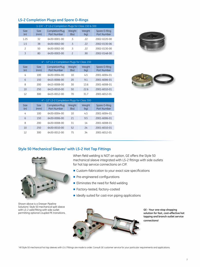
LS-2 Completion Plugs and Spare O-Rings1-1/4” - 3” LS-2 Completion Plugs for Class 150 & 300
Size (in)
Size (mm)
Completion Plug Part Number
Weight (lbs)
Weight (kg)
Spare O-Ring Part Number
1.25 32 6430-0001-00 .5 .22 2002-0220-00
1.5 38 6430-0002-00 .5 .22 2002-0130-06
2 50 6430-0002-00 .5 .22 2002-0130-00
3 80 6430-0003-00 2 .90 2002-0148-00
4” - 12” LS-2 Completion Plugs for Class 150
Size (in)
Size (mm)
Completion Plug Part Number
Weight (lbs)
Weight (kg)
Spare O-Ring Part Number
4 100 6430-0004-00 10 4.5 2001-6004-01
6 150 6415-0006-00 20 9.1 2001-6006-01
8 200 6415-0008-00 30 13.6 2001-6008-01
10 250 6415-0010-00 50 22.6 2001-6010-01
12 300 6415-0012-00 70 31.7 2001-6012-01
4” - 12” LS-2 Completion Plugs for Class 300
Size (in)
Size (mm)
Completion Plug Part Number
Weight (lbs)
Weight (kg)
Spare O-Ring Part Number
4 100 6430-0004-00 10 4.5 2001-6004-01
6 150 6430-0006-00 21 9.5 2001-6006-01
8 200 6430-0008-00 31 14 2001-6008-01
10 250 6430-0010-00 52 24 2001-6010-01
12 300 6430-0012-00 75 34 2001-6012-01
Style 50 Mechanical Sleeves1 with LS-2 Hot Tap Fittings
When field welding is NOT an option, GE offers the Style 50 mechanical sleeve integrated with LS-2 fittings with side outlets for hot tap service connections on CIP.
■■ Custom-fabrication to your exact size specifications
■■ Pre-engineered configurations
■■ Eliminates the need for field welding
■■ Factory-tested, factory-coated
■■ Ideally suited for cast-iron piping applications
Shown above is a Dresser Pipeline Solutions’ Style 50 mechanical split sleeve with LS-2 weld fitting with side outlet permitting optional coupled PE transitions.
GE - Your one-stop shopping solution for fast, cost-effective hot tapping and branch outlet service connections!
1 All Style 50 mechanical hot tap sleeves with LS-2 fittings are made to order. Consult GE customer service for your particular requirements and applications.
8
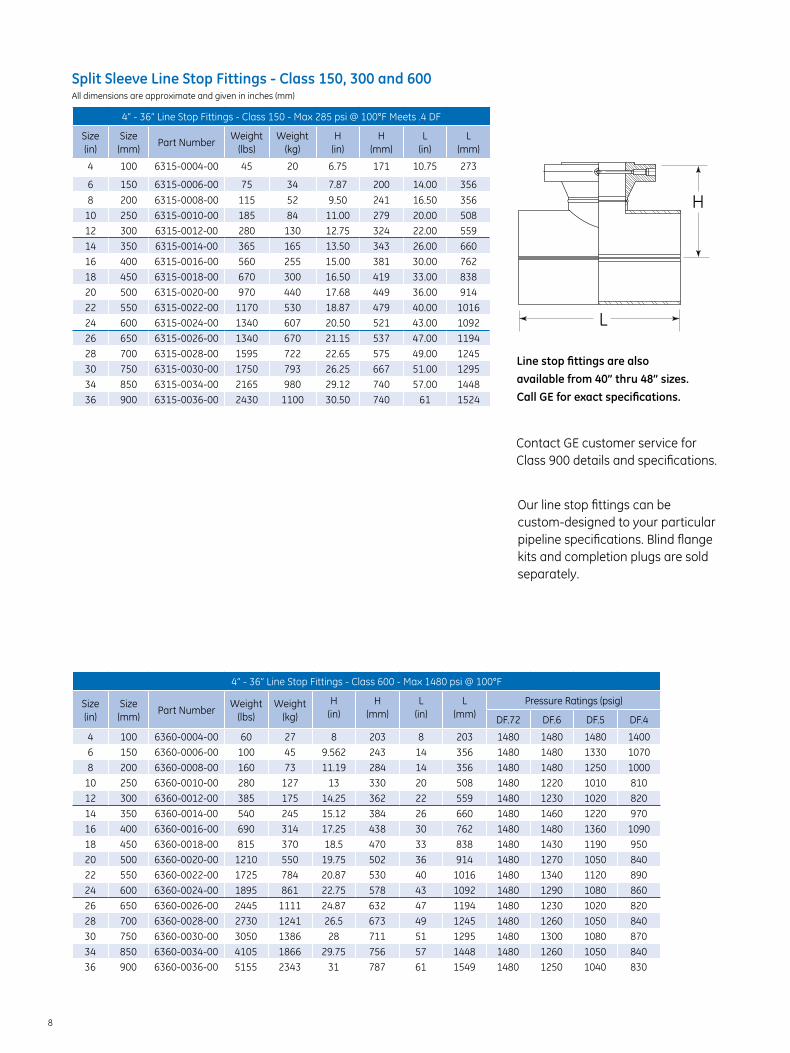
Split Sleeve Line Stop Fittings - Class 150, 300 and 600 All dimensions are approximate and given in inches (mm)
4” - 36” Line Stop Fittings - Class 150 - Max 285 psi @ 100°F Meets .4 DF
Size (in)
Size (mm)
Part NumberWeight
(lbs)Weight
(kg)H
(in)H
(mm)L
(in)L
(mm)
4 100 6315-0004-00 45 20 6.75 171 10.75 273
6 150 6315-0006-00 75 34 7.87 200 14.00 356
8 200 6315-0008-00 115 52 9.50 241 16.50 356
10 250 6315-0010-00 185 84 11.00 279 20.00 508
12 300 6315-0012-00 280 130 12.75 324 22.00 559
14 350 6315-0014-00 365 165 13.50 343 26.00 660
16 400 6315-0016-00 560 255 15.00 381 30.00 762
18 450 6315-0018-00 670 300 16.50 419 33.00 838
20 500 6315-0020-00 970 440 17.68 449 36.00 914
22 550 6315-0022-00 1170 530 18.87 479 40.00 1016
24 600 6315-0024-00 1340 607 20.50 521 43.00 1092
26 650 6315-0026-00 1340 670 21.15 537 47.00 1194
28 700 6315-0028-00 1595 722 22.65 575 49.00 1245
30 750 6315-0030-00 1750 793 26.25 667 51.00 1295
34 850 6315-0034-00 2165 980 29.12 740 57.00 1448
36 900 6315-0036-00 2430 1100 30.50 740 61 1524
Line stop fittings are also available from 40” thru 48” sizes. Call GE for exact specifications.
Our line stop fittings can be custom-designed to your particular pipeline specifications. Blind flange kits and completion plugs are sold separately.
Contact GE customer service for Class 900 details and specifications.
4” - 36” Line Stop Fittings - Class 600 - Max 1480 psi @ 100°F
Size (in)
Size (mm)
Part NumberWeight
(lbs)Weight
(kg)
H (in)
H (mm)
L (in)
L (mm)
Pressure Ratings (psig)
DF.72 DF.6 DF.5 DF.4
4 100 6360-0004-00 60 27 8 203 8 203 1480 1480 1480 1400
6 150 6360-0006-00 100 45 9.562 243 14 356 1480 1480 1330 1070
8 200 6360-0008-00 160 73 11.19 284 14 356 1480 1480 1250 1000
10 250 6360-0010-00 280 127 13 330 20 508 1480 1220 1010 810
12 300 6360-0012-00 385 175 14.25 362 22 559 1480 1230 1020 820
14 350 6360-0014-00 540 245 15.12 384 26 660 1480 1460 1220 970
16 400 6360-0016-00 690 314 17.25 438 30 762 1480 1480 1360 1090
18 450 6360-0018-00 815 370 18.5 470 33 838 1480 1430 1190 950
20 500 6360-0020-00 1210 550 19.75 502 36 914 1480 1270 1050 840
22 550 6360-0022-00 1725 784 20.87 530 40 1016 1480 1340 1120 890
24 600 6360-0024-00 1895 861 22.75 578 43 1092 1480 1290 1080 860
26 650 6360-0026-00 2445 1111 24.87 632 47 1194 1480 1230 1020 820
28 700 6360-0028-00 2730 1241 26.5 673 49 1245 1480 1260 1050 840
30 750 6360-0030-00 3050 1386 28 711 51 1295 1480 1300 1080 870
34 850 6360-0034-00 4105 1866 29.75 756 57 1448 1480 1260 1050 840
36 900 6360-0036-00 5155 2343 31 787 61 1549 1480 1250 1040 830
H
L

9
Split Sleeve Line Stop Fittings w/Side Outlet - Class 150, 300 and 600
4” - 30” Split Sleeve Line Stop Fittings w/Side Outlet @ 100° F
Size (in)
Size (mm)
Class 150 Max 285 psi
@ 100°F Meets .4 DF
Part Number
Weight (lbs)
Weight (kg)
Class 300 Max 740 psi
@ 100°F Meets .4 DF
Part Number
Weight (lbs)
Weight (kg)
Class 600 Max 1480 psi
@ 100°F Meets .72 DF Part Number
Weight (lbs)
Weight (kg)
4 100 6313-1504-00 60 26 6313-3004-00 70 32 6313-6004-00 73 33
6 150 6313-1506-00 105 48 6313-3006-00 123 56 6313-6006-00 130 60
8 200 6313-1508-00 175 80 6313-3008-00 186 84 6313-6008-00 220 100
10 250 6313-1510-00 290 132 6313-3010-00 286 130 6313-6010-00 385 175
12 300 6313-1512-00 420 190 6313-3012-00 447 203 6313-6012-00 528 240
14 350 6313-1514-00 570 258 6313-3014-00 636 288 6313-6014-00 746 338
16 400 6313-1516-00 830 377 6313-3016-00 802 363 6313-6016-00 955 433
18 450 6313-1518-00 990 450 6313-3018-00 1018 462 6313-6018-00 1133 514
20 500 6313-1520-00 1340 608 6313-3020-00 1489 675 6313-6020-00 1579 716
22 550 6313-1522-00 1630 740 6313-3022-00 1630 740 6313-6022-00 2189 1000
24 600 6313-1524-00 1840 835 6313-3024-00 2355 1068 6313-6024-00 3110 1410
30 750 6313-1530-00 2670 1210 6313-3030-00 3385 1535 6313-6030-00 3976 1803
NOTE: Consult GE for custom fitting sizes and specifications to meet your particular requirements.
Split Sleeve Line Stop Fittings w/Reducing Branch - Class 150, 300 and 600 All dimensions are approximate and given in inches
NOTE: Line stop reducing Branch Fittings are also available in other sizes. Consult GE Customer Service for your particular requirements.
Blind flange kits (sold separately): 4” thru 12” nominal sizes includes blind flange, studs, nuts and non-asbestos ring gasket.
Line Stop w/Reducing Branch @ 100° F Meets .4 DF
Class 150 - Max 285 psi @ 100°F Class 300 - Max 740 psi @ 100°F
Size (in)
Weight (lbs)
Class 150 Part Number
Dim L. (in)
Dim H (in)
Class 300 Part Number
Dim L. (in)
Dim H (in)
6 x 4 60 5115-0604-00 10.75 8.50 5130-0604-00 10.75 9.00
8 x 4 70 5115-0804-00 10.75 9.50 5130-0804-00 10.75 10.00
10 x 6 130 5115-1006-00 14.00 11.25 5130-1006-00 14.00 11.25
12 x 6 175 5115-1206-00 14.00 12.25 5130-1206-00 14.00 12.75
14 x 8 220 5115-1408-00 16.50 13.50 5130-1408-00 16.50 13.75
16 x 12 320 5115-1612-00 22.00 15.00 5130-1612-00 22.00 15.50
20 x 12 530 5115-2012-00 22.00 17.00 5130-2012-00 22.00 17.50
Line Stop w/Reducing Branch - Class 600 - Max 1480 psi @ 100°F Meets .72 DF
Size (in)
Weight (lbs)
Class 600 Part Number
Dim L. (in)
Dim H (in)
6 x 4 80 5160-0604-00 10.75 9.50
8 x 4 90 5160-0804-00 10.75 10.50
10 x 6 175 5160-1006-00 14.00 12.25
12 x 6 200 5160-1206-00 14.00 13.50
14 x 8 295 5160-1408-00 16.50 14.75
16 x 12 495 5160-1612-00 22.00 16.75
20 x 12 680 5160-2012-00 22.00 19.00
H
L
10
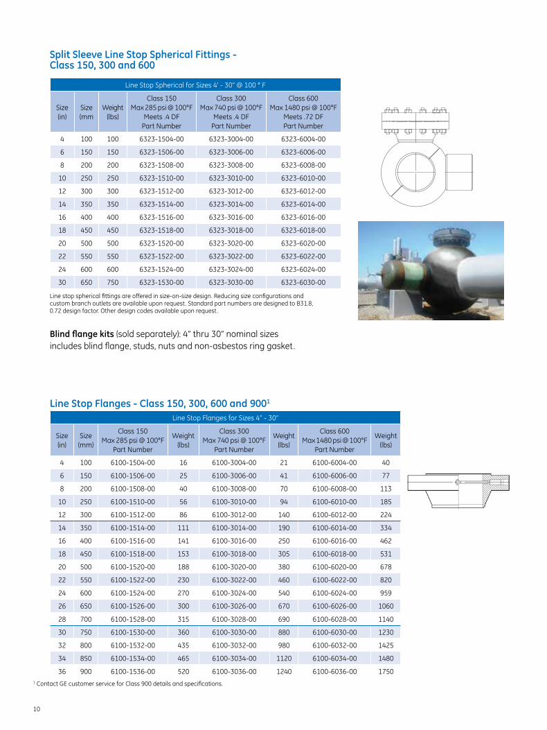
Split Sleeve Line Stop Spherical Fittings - Class 150, 300 and 600
Line Stop Spherical for Sizes 4’ - 30” @ 100 ° F
Size (in)
Size (mm
Weight (lbs)
Class 150 Max 285 psi @ 100°F
Meets .4 DF Part Number
Class 300 Max 740 psi @ 100°F
Meets .4 DF Part Number
Class 600 Max 1480 psi @ 100°F
Meets .72 DF Part Number
4 100 100 6323-1504-00 6323-3004-00 6323-6004-00
6 150 150 6323-1506-00 6323-3006-00 6323-6006-00
8 200 200 6323-1508-00 6323-3008-00 6323-6008-00
10 250 250 6323-1510-00 6323-3010-00 6323-6010-00
12 300 300 6323-1512-00 6323-3012-00 6323-6012-00
14 350 350 6323-1514-00 6323-3014-00 6323-6014-00
16 400 400 6323-1516-00 6323-3016-00 6323-6016-00
18 450 450 6323-1518-00 6323-3018-00 6323-6018-00
20 500 500 6323-1520-00 6323-3020-00 6323-6020-00
22 550 550 6323-1522-00 6323-3022-00 6323-6022-00
24 600 600 6323-1524-00 6323-3024-00 6323-6024-00
30 650 750 6323-1530-00 6323-3030-00 6323-6030-00
Line stop spherical fittings are offered in size-on-size design. Reducing size configurations and custom branch outlets are available upon request. Standard part numbers are designed to B31.8, 0.72 design factor. Other design codes available upon request.
Blind flange kits (sold separately): 4” thru 30” nominal sizes includes blind flange, studs, nuts and non-asbestos ring gasket.
Line Stop Flanges - Class 150, 300, 600 and 9001
Line Stop Flanges for Sizes 4” - 30”
Size (in)
Size (mm)
Class 150 Max 285 psi @ 100°F
Part Number
Weight (lbs)
Class 300 Max 740 psi @ 100°F
Part Number
Weight (lbs)
Class 600 Max 1480 psi @ 100°F
Part Number
Weight (lbs)
4 100 6100-1504-00 16 6100-3004-00 21 6100-6004-00 40
6 150 6100-1506-00 25 6100-3006-00 41 6100-6006-00 77
8 200 6100-1508-00 40 6100-3008-00 70 6100-6008-00 113
10 250 6100-1510-00 56 6100-3010-00 94 6100-6010-00 185
12 300 6100-1512-00 86 6100-3012-00 140 6100-6012-00 224
14 350 6100-1514-00 111 6100-3014-00 190 6100-6014-00 334
16 400 6100-1516-00 141 6100-3016-00 250 6100-6016-00 462
18 450 6100-1518-00 153 6100-3018-00 305 6100-6018-00 531
20 500 6100-1520-00 188 6100-3020-00 380 6100-6020-00 678
22 550 6100-1522-00 230 6100-3022-00 460 6100-6022-00 820
24 600 6100-1524-00 270 6100-3024-00 540 6100-6024-00 959
26 650 6100-1526-00 300 6100-3026-00 670 6100-6026-00 1060
28 700 6100-1528-00 315 6100-3028-00 690 6100-6028-00 1140
30 750 6100-1530-00 360 6100-3030-00 880 6100-6030-00 1230
32 800 6100-1532-00 435 6100-3032-00 980 6100-6032-00 1425
34 850 6100-1534-00 465 6100-3034-00 1120 6100-6034-00 1480
36 900 6100-1536-00 520 6100-3036-00 1240 6100-6036-00 17501 Contact GE customer service for Class 900 details and specifications.
11
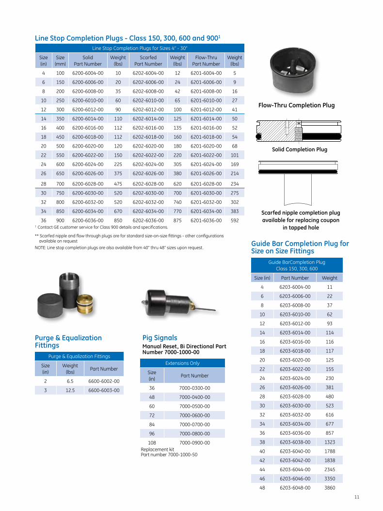
Line Stop Completion Plugs - Class 150, 300, 600 and 9001
Line Stop Completion Plugs for Sizes 4” - 30”
Size (in)
Size (mm)
Solid Part Number
Weight (lbs)
Scarfed Part Number
Weight (lbs)
Flow-Thru Part Number
Weight (lbs)
4 100 6200-6004-00 10 6202-6004-00 12 6201-6004-00 5
6 150 6200-6006-00 20 6202-6006-00 24 6201-6006-00 9
8 200 6200-6008-00 35 6202-6008-00 42 6201-6008-00 16
10 250 6200-6010-00 60 6202-6010-00 65 6201-6010-00 27
12 300 6200-6012-00 90 6202-6012-00 100 6201-6012-00 41
14 350 6200-6014-00 110 6202-6014-00 125 6201-6014-00 50
16 400 6200-6016-00 112 6202-6016-00 135 6201-6016-00 52
18 450 6200-6018-00 112 6202-6018-00 160 6201-6018-00 54
20 500 6200-6020-00 120 6202-6020-00 180 6201-6020-00 68
22 550 6200-6022-00 150 6202-6022-00 220 6201-6022-00 101
24 600 6200-6024-00 225 6202-6024-00 305 6201-6024-00 169
26 650 6200-6026-00 375 6202-6026-00 380 6201-6026-00 214
28 700 6200-6028-00 475 6202-6028-00 620 6201-6028-00 234
30 750 6200-6030-00 520 6202-6030-00 700 6201-6030-00 275
32 800 6200-6032-00 520 6202-6032-00 740 6201-6032-00 302
34 850 6200-6034-00 670 6202-6034-00 770 6201-6034-00 383
36 900 6200-6036-00 850 6202-6036-00 875 6201-6036-00 5921 Contact GE customer service for Class 900 details and specifications.
** Scarfed nipple and flow through plugs are for standard size-on-size fittings - other configurations available on request
NOTE: Line stop completion plugs are also available from 40” thru 48” sizes upon request.
Purge & Equalization Fittings
Purge & Equalization Fittings
Size (in)
Weight (lbs)
Part Number
2 6.5 6600-6002-00
3 12.5 6600-6003-00
Pig Signals Manual Reset, Bi Directional Part Number 7000-1000-00
Extensions Only
Size (in)
Part Number
36 7000-0300-00
48 7000-0400-00
60 7000-0500-00
72 7000-0600-00
84 7000-0700-00
96 7000-0800-00
108 7000-0900-00Replacement kit Part number 7000-1000-50
Flow-Thru Completion Plug
Solid Completion Plug
Scarfed nipple completion plug available for replacing coupon
in tapped hole
Guide BarCompletion Plug Class 150, 300, 600
Size (in) Part Number Weight
4 6203-6004-00 11
6 6203-6006-00 22
8 6203-6008-00 37
10 6203-6010-00 62
12 6203-6012-00 93
14 6203-6014-00 114
16 6203-6016-00 116
18 6203-6018-00 117
20 6203-6020-00 125
22 6203-6022-00 155
24 6203-6024-00 230
26 6203-6026-00 381
28 6203-6028-00 480
30 6203-6030-00 523
32 6203-6032-00 616
34 6203-6034-00 677
36 6203-6036-00 857
38 6203-6038-00 1323
40 6203-6040-00 1788
42 6203-6042-00 1838
44 6203-6044-00 2345
46 6203-6046-00 3350
48 6203-6048-00 3860
Guide Bar Completion Plug for Size on Size Fittings
12
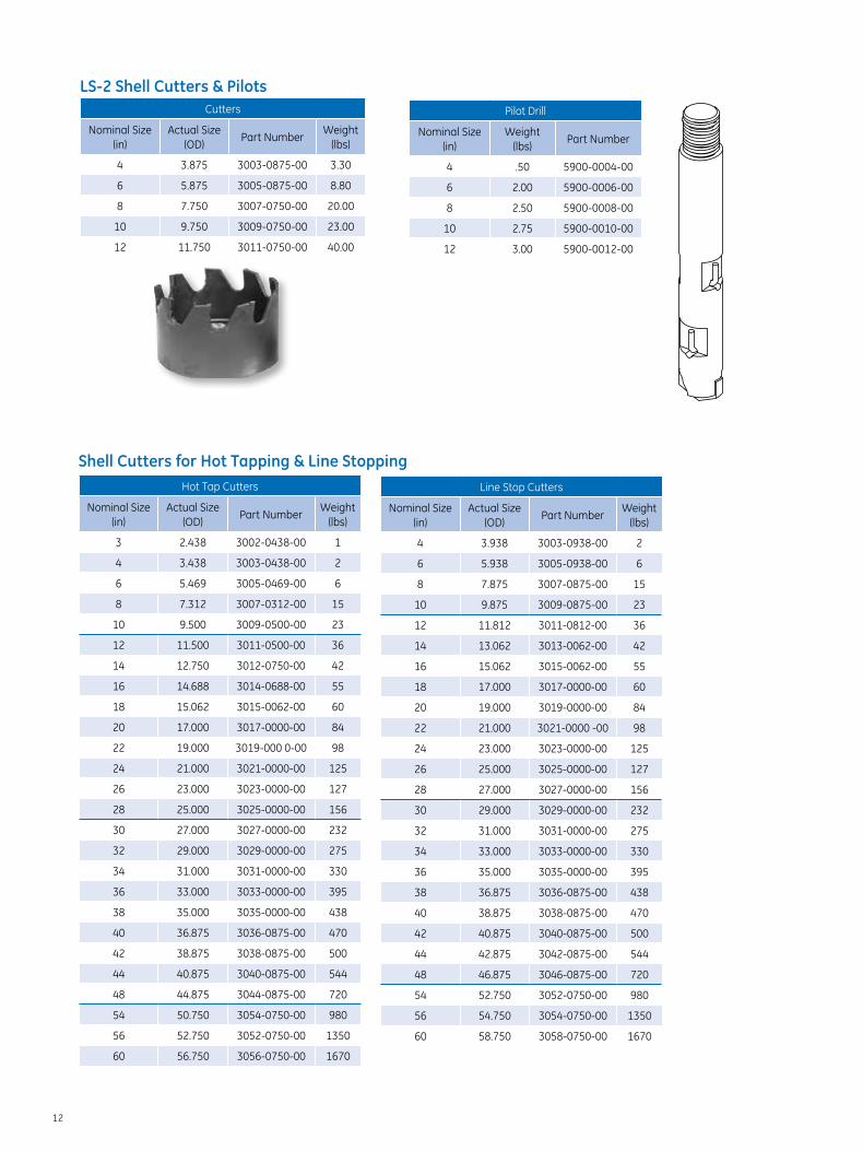
LS-2 Shell Cutters & PilotsCutters
Nominal Size (in)
Actual Size (OD)
Part NumberWeight
(lbs)
4 3.875 3003-0875-00 3.30
6 5.875 3005-0875-00 8.80
8 7.750 3007-0750-00 20.00
10 9.750 3009-0750-00 23.00
12 11.750 3011-0750-00 40.00
Hot Tap Cutters
Nominal Size (in)
Actual Size (OD)
Part NumberWeight
(lbs)
3 2.438 3002-0438-00 1
4 3.438 3003-0438-00 2
6 5.469 3005-0469-00 6
8 7.312 3007-0312-00 15
10 9.500 3009-0500-00 23
12 11.500 3011-0500-00 36
14 12.750 3012-0750-00 42
16 14.688 3014-0688-00 55
18 15.062 3015-0062-00 60
20 17.000 3017-0000-00 84
22 19.000 3019-000 0-00 98
24 21.000 3021-0000-00 125
26 23.000 3023-0000-00 127
28 25.000 3025-0000-00 156
30 27.000 3027-0000-00 232
32 29.000 3029-0000-00 275
34 31.000 3031-0000-00 330
36 33.000 3033-0000-00 395
38 35.000 3035-0000-00 438
40 36.875 3036-0875-00 470
42 38.875 3038-0875-00 500
44 40.875 3040-0875-00 544
48 44.875 3044-0875-00 720
54 50.750 3054-0750-00 980
56 52.750 3052-0750-00 1350
60 56.750 3056-0750-00 1670
Shell Cutters for Hot Tapping & Line StoppingLine Stop Cutters
Nominal Size (in)
Actual Size (OD)
Part NumberWeight
(lbs)
4 3.938 3003-0938-00 2
6 5.938 3005-0938-00 6
8 7.875 3007-0875-00 15
10 9.875 3009-0875-00 23
12 11.812 3011-0812-00 36
14 13.062 3013-0062-00 42
16 15.062 3015-0062-00 55
18 17.000 3017-0000-00 60
20 19.000 3019-0000-00 84
22 21.000 3021-0000 -00 98
24 23.000 3023-0000-00 125
26 25.000 3025-0000-00 127
28 27.000 3027-0000-00 156
30 29.000 3029-0000-00 232
32 31.000 3031-0000-00 275
34 33.000 3033-0000-00 330
36 35.000 3035-0000-00 395
38 36.875 3036-0875-00 438
40 38.875 3038-0875-00 470
42 40.875 3040-0875-00 500
44 42.875 3042-0875-00 544
48 46.875 3046-0875-00 720
54 52.750 3052-0750-00 980
56 54.750 3054-0750-00 1350
60 58.750 3058-0750-00 1670
Pilot Drill
Nominal Size (in)
Weight (lbs)
Part Number
4 .50 5900-0004-00
6 2.00 5900-0006-00
8 2.50 5900-0008-00
10 2.75 5900-0010-00
12 3.00 5900-0012-00

13
Pilot Drills for Hot Tapping and Line StoppingPilots
Size (in)
Weight (lbs)
Part Number
3 .50 5900-0003-00
4 .50 5900-0004-00
6 2.00 5900-0006-00
8 2.50 5900-0008-00
10 2.75 5900-0010-00
12 3.00 5900-0012-00
14 5.50 5900-0014-00
16 6.00 5900-0016-00
Pilots
Size (in)
Weight (lbs)
Part Number
12 6.00 8300-0012-00
14 6.50 8300-0014-00
16 7.00 8300-0016-00
18 7.00 8300-0018-00
20 7.50 8300-0020-00
22 8.50 8300-0022-00
24 9.00 8300-0024-00
26 10,50 8300-0026-00
28 11.00 8300-0028-00
30 12.00 8300-0030-00
32 15.00 8300-0032-00
34 15.00 8300-0034-00
36 18.00 8300-0036-00
38 20.00 8300-0038-00
40 22.00 8300-0040-00
42 24.00 8300-0042-00
44 28.00 8300-0044-00
48 34.00 8300-0048-00
Spare U-Rods for All Pilots
Pilot Size Range (in)
U-Rod Part Number
3-4 UR-00-1
6-12 UR-00-2
14-42 UR-00-3
44-48 UR-00-4
GE provides complete cutter and pilot repair and sharpening service. Cutters and pilots for special applications are available upon request.
Accessories for M4 Tapping Machines
Twist Drill for M4 Tapping Machines
Size (in)
Description Part Number
1/2 Standard Length Twist Drill 7600-0008-00
1/2 Extended Length Twist Drill 7601-0008-00
3/4 Standard Length Twist Drill 7600-0012-00
3/4 Extended Length Twist Drill 7601-0012-00
1 Standard Length Twist Drill 7600-0016-00
1 Extended Length Twist Drill 7601-0016-00
1-1/4 Standard Length Twist Drill 7600-0020-00
1-7/16 Standard Twist Drill 7600-0023-00
Nominal Hole Saw for M4 Tapping Machines
Size (in)
Description Part Number
1-1/4 Nominal Hole Saw 3101-0312-00
1-1/2 Nominal Hole Saw 3101-0562-00
2 Nominal Hole Saw 3101-0875-00
3 Nominal Hole Saw 3102-0875-00
4 Nominal Hole Saw 3103-0875-00
6 Nominal Hole Saw* 3105-0875-00
Holder PilotsSize-on-Size Holder for Hot Taps
Size (in)
Description Part Number
1-1/4 Size-on-Size Holder 7500-0101-10
1-1/2 Size-on-Size Holder 7500-0102-10
2- 3 Size-on-Size Holder 7500-0103-10
4 Size-on-Size Holder 7500-0104-10
6 Size-on-Size Holder 7500-0106-10
Other Holders
Size (in)
Description Part Number
1-1/4-1-1/2 Holder 7500-0202-10
2-3 Holder 7500-0203-10
4 Holder 7500-0204-10
6 Holder 7500-0206-10
Other Than Size-on-Size Hot Taps
Twist Drills
14
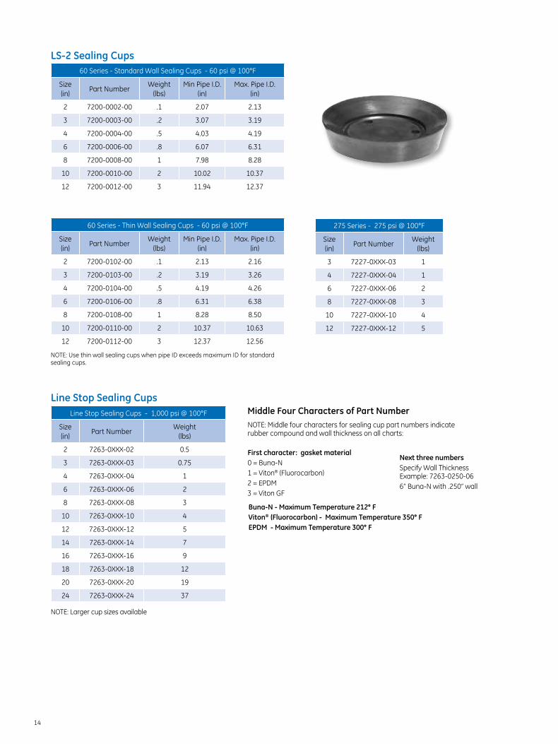
60 Series - Standard Wall Sealing Cups - 60 psi @ 100°F
Size (in)
Part NumberWeight
(lbs)Min Pipe I.D.
(in)Max. Pipe I.D.
(in)
2 7200-0002-00 .1 2.07 2.13
3 7200-0003-00 .2 3.07 3.19
4 7200-0004-00 .5 4.03 4.19
6 7200-0006-00 .8 6.07 6.31
8 7200-0008-00 1 7.98 8.28
10 7200-0010-00 2 10.02 10.37
12 7200-0012-00 3 11.94 12.37
LS-2 Sealing Cups
60 Series - Thin Wall Sealing Cups - 60 psi @ 100°F
Size (in)
Part NumberWeight
(lbs)Min Pipe I.D.
(in)Max. Pipe I.D.
(in)
2 7200-0102-00 .1 2.13 2.16
3 7200-0103-00 .2 3.19 3.26
4 7200-0104-00 .5 4.19 4.26
6 7200-0106-00 .8 6.31 6.38
8 7200-0108-00 1 8.28 8.50
10 7200-0110-00 2 10.37 10.63
12 7200-0112-00 3 12.37 12.56
275 Series - 275 psi @ 100°F
Size (in)
Part NumberWeight
(lbs)
3 7227-0XXX-03 1
4 7227-0XXX-04 1
6 7227-0XXX-06 2
8 7227-0XXX-08 3
10 7227-0XXX-10 4
12 7227-0XXX-12 5
NOTE: Use thin wall sealing cups when pipe ID exceeds maximum ID for standard sealing cups.
Line Stop Sealing Cups - 1,000 psi @ 100°F
Size (in)
Part NumberWeight
(lbs)
2 7263-0XXX-02 0.5
3 7263-0XXX-03 0.75
4 7263-0XXX-04 1
6 7263-0XXX-06 2
8 7263-0XXX-08 3
10 7263-0XXX-10 4
12 7263-0XXX-12 5
14 7263-0XXX-14 7
16 7263-0XXX-16 9
18 7263-0XXX-18 12
20 7263-0XXX-20 19
24 7263-0XXX-24 37
NOTE: Middle four characters for sealing cup part numbers indicate rubber compound and wall thickness on all charts:
First character: gasket material0 = Buna-N1 = Viton® (Fluorocarbon)2 = EPDM3 = Viton GF
Middle Four Characters of Part Number
Next three numbersSpecify Wall Thickness Example: 7263-0250-066” Buna-N with .250” wall
Buna-N - Maximum Temperature 212° FViton® (Fluorocarbon) - Maximum Temperature 350° FEPDM - Maximum Temperature 300° F
Line Stop Sealing Cups
NOTE: Larger cup sizes available
15
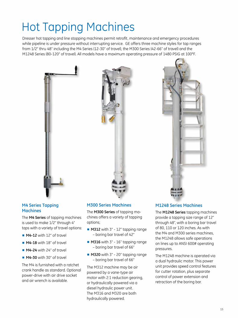
Hot Tapping MachinesDresser hot tapping and line stopping machines permit retrofit, maintenance and emergency procedures while pipeline is under pressure without interrupting service. GE offers three machine styles for tap ranges from 1/2” thru 48” including the M4 Series (12-30” of travel), the M300 Series (42-66” of travel) and the M1248 Series (80-120” of travel). All models have a maximum operating pressure of 1480 PSIG at 100°F.
M4 Series Tapping MachinesThe M4 Series of tapping machines is used to make 1/2” through 4” taps with a variety of travel options:
■■ M4-12 with 12” of travel
■■ M4-18 with 18” of travel
■■ M4-24 with 24” of travel
■■ M4-30 with 30” of travel
The M4 is furnished with a ratchet crank handle as standard. Optional power-drive with air drive socket and air wrench is available.
M300 Series MachinesThe M300 Series of tapping ma-chines offers a variety of tapping options;
■■ M312 with 3” - 12” tapping range – boring bar travel of 42”
■■ M316 with 3” - 16” tapping range – boring bar travel of 66”
■■ M320 with 3” - 20” tapping range – boring bar travel of 66”
The M312 machine may be air powered by a vane-type air motor with 2:1 reduction gearing, or hydraulically powered via a diesel hydraulic power unit. The M316 and M320 are both hydraulically powered.
M1248 Series MachinesThe M1248 Series tapping machines provide a tapping size range of 12” through 48”, with a boring bar travel of 80, 110 or 120 inches. As with the M4 and M300 series machines, the M1248 allows safe operations on lines up to ANSI 600# operating pressures.
The M1248 machine is operated via a dual hydraulic motor. This power unit provides speed control features for cutter rotation, plus separate control of power extension and retraction of the boring bar.
16
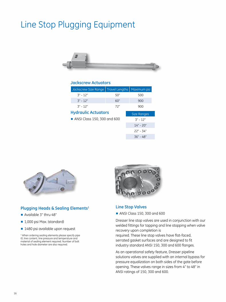
Plugging Heads & Sealing Elements1
■■ Available 3” thru 48”
■■ 1,000 psi Max. (standard)
■■ 1480 psi available upon request
Line Stop Plugging Equipment
Hydraulic Actuators■■ ANSI Class 150, 300 and 600
Size Ranges
3” - 12”
14” - 20”
22” - 34”
36” - 48”
Jackscrew ActuatorsJackscrew Size Range Travel Lengths Maximum psi
3” - 12” 50” 500
3” - 12” 60” 900
3” - 12” 72” 900
Line Stop Valves■■ ANSI Class 150, 300 and 600
Dresser line stop valves are used in conjunction with our welded fittings for tapping and line stopping when valve recovery upon completion is required. These line stop valves have flat-faced, serrated gasket surfaces and are designed to fit industry standard ANSI 150, 300 and 600 flanges.
As an operational safety feature, Dresser pipeline solutions valves are supplied with an internal bypass for pressure equalization on both sides of the gate before opening. These valves range in sizes from 4” to 48” in ANSI ratings of 150, 300 and 600.
1 When ordering sealing elements please specify pipe ID, line content, line pressure and temperature and material of sealing element required. Number of bolt holes and hole diameter are also required.

17
Line Stop Housing & Tapping Adapters■■ ANSI Class 150, 300 and 600
■■ Available 3” thru 48”
■■ Raised face or RTJ
Hydraulic Power UnitsDresser hydraulic power units are skid-mounted with a diesel engine and supplied with a set of 50-foot hoses.
Equipment Repair ServicesService engineers understand the importance of maintaining operating efficiency and having dependable equipment readily available. Our skilled repair technicians are professionally trained to service your tapping equipment and guarantee it’s returned in proper working condition.
18
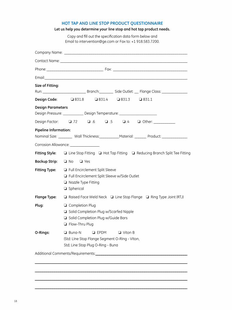
HOT TAP AND LINE STOP PRODUCT QUESTIONNAIRELet us help you determine your line stop and hot tap product needs.
Copy and fill out the specification data form below and Email to [email protected] or Fax to: +1 918.583.7200.
Company Name: _______________________________________________________________
Contact Name: _________________________________________________________________
Phone: _____________________________ Fax: ______________________________________
Email:_________________________________________________________________________
Size of Fitting: Run: ______________________ Branch:_______ Side Outlet: __ Flange Class: _____________
Design Code: o B31.8 o B31.4 o B31.3 o■B31.1
Design Parameters
Design Pressure: _____________ Design Temperature: ________________________
Design Factor: o .72 o .6 o .5 o .4 o■■Other: ___________
Pipeline Information:
Nominal Size: _______ Wall Thickness:__________Material: ______ Product: _____________
Corrosion Allowance: _______________
Fitting Style: o Line Stop Fitting o Hot Tap Fitting o Reducing Branch Split Tee Fitting
Backup Strip: o No o Yes
Fitting Type: o Full Encirclement Split Sleeve
o Full Encirclement Split Sleeve w/Side Outlet
o Nozzle Type Fitting
o Spherical
Flange Type: o Raised Face Weld Neck o Line Stop Flange o Ring Type Joint (RTJ)
Plug: o■ Completion Plug
o■ Solid Completion Plug w/Scarfed Nipple
o■ Solid Completion Plug w/Guide Bars
o■ Flow-Thru Plug
O-Rings: o Buna-N o EPDM o Viton B
(Std: LIne Stop Flange Segment O-RIng - VIton,
Std; Line Stop Plug O-Ring - Buna
Additional Comments/Requirements: _______________________________________________
______________________________________________________________________________
______________________________________________________________________________
______________________________________________________________________________
______________________________________________________________________________

GE Oil & Gas
Houston, TX 16240 Port Northwest Drive, Suite 100 Houston Texas 77041-2645, U.S.A. +1 832.590.2303
Bradford, PA 41 Fisher Avenue, Bradford, PA 16701, U.S.A. T: +1 814.362.9200 F: +1 814.362.9344
Tulsa, OK 4235 South 68th East Avenue, Tulsa, OK 74145-4617, U.S.A. T: +1 918.583.3000 F: +1 918.583.7200
Email: [email protected]
Visit us online at: www.ge-energy.com
©2014 General Electric Company All Rights Reserved
*Denotes trademark of General Electric Company
UAE Office 2306, JAFZA Views 19 Jebel Ali Free Zone, Dubai United Arab Emirates
Turkey Maslak Mah. Bilim Sok. 5, Sun Plaza, Kat 5 34398, Sisli, Istanbul, Turkey
United Kingdom Dresser House, Gillibrands Rd, Skelmersdale, Lancashire, WN8 9TU, United Kingdom
Malaysia Suite 18-1, Wisma UOA II 21, Jalan Pinang, 50450 Kuala Lumpur Malaysia
Mexico Dresser de Mexico S.A. de C.V. Emiliano Zapata No. 53 Col San Jose Buenavista Cuatitlan Izcalli, Estado de México 54710 Mexico
GEA19168A 11/2014


![Free Dresser[1]](https://static.fdocuments.us/doc/165x107/577d35a91a28ab3a6b910d4e/free-dresser1.jpg)