DRDB: BAAQMD ST34 - BULK AND MARINE LOADING … · BULK AND MARINE LOADING TERMINALS VAPOR RECOVERY...
29
Bay Area Air Quality Management District Amended 12/21/94 ST-34-1 Source Test Procedure ST-34 BULK AND MARINE LOADING TERMINALS VAPOR RECOVERY UNITS (Adopted October 7, 1987) REF: Regulations 8-33-301, 308, 309, 8-6-302.1 and 8-44-301 1. APPLICABILITY 1.1 This procedure is applicable for quantifying the non-methan e organic carbon (NMOC) emissions from organic compound bulk distribution and marine loading terminals that utilize refrigeration, carbon adsorption, or incineration vapor recovery systems (VRS). It is applicable for the determination of compliance with Regulation 8-33-301, 308, and 309 and Regulation 8-6- 302.1, and 8-44-301. 2. PRINCIPLE 2.1 For refrigeration or carbon adsorption units, the exhaust gas volume and NMOC outlet concentrations are continuously monitored at the VRS outlets. From these parameters, and the total volume of organic liquid loaded, the emission factor of the VRS is determined. In some instances, the exhaust gas volume cannot be accurately measured. Using carbon vessel volume, purge and back flow volume, carbon density, loading information, and inlet and outlet NMOC concentrations, the outlet volumes can be calculated. 2.2.1 A Flame Ionization Detector (FID) may be used for the measurement of Total Organic Carbon (TOC) provided that the product of the percentages of CO 2 and H 2 O vapor in the gas stream do not exceed 100. In this event, the applicable EPA Reference Method shall be used. 2.2 For incineration units, the TOC concentration and inlet volume to the incinerator are monitored. The TOC, carbon dioxide, and carbon monoxide concentrations in the exhaust gas are also continuously measured and recorded. From these parameters, and the total volume of organic liquid loaded, the emission factor of the VRS is determined. 2.3 The methane content of the sample shall be determined by either (a) integrated sampling and GC/FID analysis using EPA Method 18 or BAAQMD Laboratory Method 17 or (b) directing a potion of the conditioned sample through a bed of activated carbon, for NMOC adsorption, prior to the hydrocarbon analyzer. 2.4 The NMOC concentration and exhaust volume from the vapor storage tank (VST) are continuously monitored and recorded during the test. From these parameters, the average NMOC concentration and mass emission rate are determined.
-
Upload
hoangkhanh -
Category
Documents
-
view
230 -
download
4
Transcript of DRDB: BAAQMD ST34 - BULK AND MARINE LOADING … · BULK AND MARINE LOADING TERMINALS VAPOR RECOVERY...
Bay Area Air Quality Management District Amended 12/21/94
ST-34-1
Source Test Procedure ST-34
BULK AND MARINE LOADING TERMINALSVAPOR RECOVERY UNITS
(Adopted October 7, 1987)
REF: Regulations 8-33-301, 308, 309, 8-6-302.1 and 8-44-301
1. APPLICABILITY
1.1 This procedure is applicable for quantifying the non-methan e organic carbon(NMOC) emissions from organic compound bulk distribution and marineloading terminals that utilize refrigeration, carbon adsorption, or incinerationvapor recovery systems (VRS). It is applicable for the determination ofcompliance with Regulation 8-33-301, 308, and 309 and Regulation 8-6-302.1, and 8-44-301.
2. PRINCIPLE
2.1 For refrigeration or carbon adsorption units, the exhaust gas volume andNMOC outlet concentrations are continuously monitored at the VRS outlets.From these parameters, and the total volume of organic liquid loaded, theemission factor of the VRS is determined. In some instances, the exhaust gasvolume cannot be accurately measured. Using carbon vessel volume, purgeand back flow volume, carbon density, loading information, and inlet andoutlet NMOC concentrations, the outlet volumes can be calculated.
2.2.1 A Flame Ionization Detector (FID) may be used for the measurementof Total Organic Carbon (TOC) provided that the product of thepercentages of CO2 and H2O vapor in the gas stream do not exceed100. In this event, the applicable EPA Reference Method shall beused.
2.2 For incineration units, the TOC concentration and inlet volume to theincinerator are monitored. The TOC, carbon dioxide, and carbon monoxideconcentrations in the exhaust gas are also continuously measured andrecorded. From these parameters, and the total volume of organic liquidloaded, the emission factor of the VRS is determined.
2.3 The methane content of the sample shall be determined by either (a)integrated sampling and GC/FID analysis using EPA Method 18 or BAAQMDLaboratory Method 17 or (b) directing a potion of the conditioned samplethrough a bed of activated carbon, for NMOC adsorption, prior to thehydrocarbon analyzer.
2.4 The NMOC concentration and exhaust volume from the vapor storage tank(VST) are continuously monitored and recorded during the test. From theseparameters, the average NMOC concentration and mass emission rate aredetermined.

MOP Volume IV, ST-34 Bulk And Marine Loading Terminals, Vapor Recovery Units
Bay Area Air Quality Management District Amended 12/21/94
ST-34-2
3. RANGE AND SENSITIVITY
3.1 The minimum and maximum measurable concentrations, as C 4, with the Non-Dispersive Infrared analyzers (NDIR) are 5 ppm and 100 percent,respectively.
3.2 The sensitivity of the NDIR analyzers shall not exceed one percent of fullscale. The zero drift and calibration drift shall not exceed two percent of thespan value. The calibration error shall not exceed three percent of thecalibration gas value.
3.3 The minimum and maximum measurable concentrations, as C 1, withthe Flame Ionization Detection hydrocarbon analyzer (FID) are 5 ppmand 100,000 ppm, respectively.
3.4 The sensitivity of the FID hydrocarbon analyzer shall not exceed onepercent of full scale. The zero drift and calibration drift shall notexceed two percent of the span value. The calibration error shall notexceed three percent of the calibration gas value.
4. INTERFERENCES
4.1 The presence of vapor or liquid leaks in the collection, or vapor processing,system may preclude the use of this method. These leaks shall be repairedprior to start of the test.
5. APPARATUS - CARBON ADSORPTION AND REFRIGERATION UNITS
5.1 Non-Dispersive Infrared Hydrocarbon Analyzers. Use two Summit AnalyzersInc, model 703, or equivalent, to continuously monitor the outletconcentrations at the carbon adsorption or refrigeration units. A third NDIRanalyzer shall be used to continuously monitor the NMOC concentration at theinlet to the units.
5.2 Turbine Meters. Use two appropriately sized Rockwell Turbine Meters, modelMark II Turbo-Meter, or equivalent, to measure the exhaust volumes from theoutlet of the carbon beds or refrigeration units. The meters shall be equippedwith temperature sensors and pressure gauges on the inlet side and a sampleport on the outlet side. Each meter shall also be equipped with a pulsegenerator, or equivalent, for remote flow monitoring. The pressure dropacross the meter shall not exceed two inches of water column (inches H 2O) ata flowrate of 1,000 cubic feet per minute.
5.2.1 Pitot Tube and Pressure Transduc er. Some installations preclude theuse of turbine meters. In this case, use an appropriately sized pitottube in conjunction with a pressure transducer, Viatran CorporationModel 219, or equivalent, to determine the velocity heads at thecenterline of the outlet duct during the test using BAAQMD SourceTest Methods 17 and 18. The output of the transducer shall becontinuously recorded on the strip chart recorder. In addition, the

MOP Volume IV, ST-34 Bulk And Marine Loading Terminals, Vapor Recovery Units
Bay Area Air Quality Management District Amended 12/21/94
ST-34-3
transducer/strip chart recorder shall differentiate and record thedirection of flow.
5.3 Rotary Gas Meter. Use a Roots Meter model 3M125, or equivalent, tomeasure the volume of purge air introduced into each carbon bed during theregeneration cycles.
5.4 Strip Chart Recorder. Use a six channel strip chart recorder, or equivalent, tocontinuously record the inlet and outlet NMOC concentrations, outlettemperatures, and flowrates from the turbine meters or pitot tube/transducerset-up.
5.5 Sample Pumps. Use leak-free Teflon lined, or equivalent, diaphragm pumpscapable of maintaining a 14.3 liter per minute (0.5 CFM) flowrate at 380millimeters of mercury (15 inches of mercury).
Figure 34-1
Zero Air Systems
5.6 Zero-Air System. This system provides nitrogen for zeroing the NDIRanalyzers and is assembled as shown in Figure 34-1.
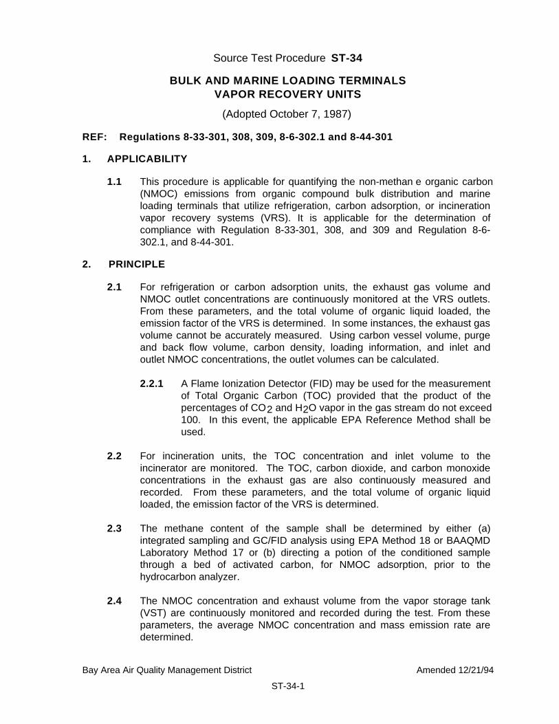
5.7 Span Gas System. This system delivers appropriate mixtures of span gas, innitrogen, for the purpose of calibrating the NDIR analyzers during the test. Thespan gas system is assembled as shown in Figure 34-2.
MOP Volume IV, ST-34 Bulk And Marine Loading Terminals, Vapor Recovery Units
Bay Area Air Quality Management District Amended 12/21/94
ST-34-4
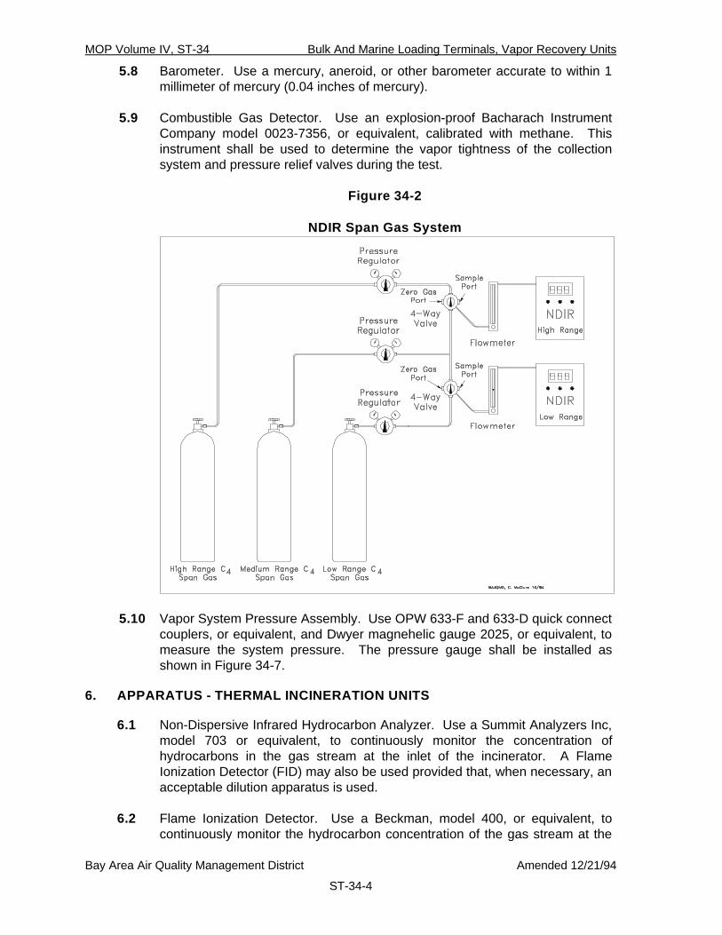
5.8 Barometer. Use a mercury, aneroid, or other barometer accurate to within 1millimeter of mercury (0.04 inches of mercury).
5.9 Combustible Gas Detector. Use an explosion-proof Bacharach InstrumentCompany model 0023-7356, or equivalent, calibrated with methane. Thisinstrument shall be used to determine the vapor tightness of the collectionsystem and pressure relief valves during the test.
Figure 34-2
NDIR Span Gas System
5.10 Vapor System Pressure Assembly. Use OPW 633-F and 633-D quick connectcouplers, or equivalent, and Dwyer magnehelic gauge 2025, or equivalent, tomeasure the system pressure. The pressure gauge shall be installed asshown in Figure 34-7.
6. APPARATUS - THERMAL INCINERATION UNITS
6.1 Non-Dispersive Infrared Hydrocarbon Analyzer. Use a Summit Analyzers Inc,model 703 or equivalent, to continuously monitor the concentration ofhydrocarbons in the gas stream at the inlet of the incinerator. A FlameIonization Detector (FID) may also be used provided that, when necessary, anacceptable dilution apparatus is used.
6.2 Flame Ionization Detector. Use a Beckman, model 400, or equivalent, tocontinuously monitor the hydrocarbon concentration of the gas stream at the

MOP Volume IV, ST-34 Bulk And Marine Loading Terminals, Vapor Recovery Units
Bay Area Air Quality Management District Amended 12/21/94
ST-34-5
exhaust of the incinerator. The FID shall be calibrated using propane.Appropriate methodology shall be employed to allow the determination of bothmethane and NMOC concentrations.
6.3 Carbon Dioxide Analyzer. Use a Summit Analyzers Inc, model 702D orequivalent, to continuously monitor the carbon dioxide concentration of thegas stream at the exhaust of the incinerator.
6.4 Carbon Monoxide Analyzer. Use a Summit Analyzers Inc, model 702D orequivalent, to continuously monitor the carbon monoxide concentration of thegas stream at the exhaust of the incinerator.
6.5 Oxygen Analyzer. Use a Summit Analyzers Inc, model 2200 or equivalent, tocontinuously monitor the oxygen concentration of the gas stream at theexhaust of the incinerator.
Figure 34-3
Sample Gas Conditioning System
6.6 Turbine Meter. Use an appropriately sized Rockwell Turbine Meter, modelMark II Turbo-Meter or equivalent, to measure the inlet volume to theincinerator. The turbine meter shall be equipped with a temperature sensorand pressure gauge on the inlet side and a sample port on the outlet side.The meter shall also be equipped with a pulse generator, or equivalent, forremote flowrate monitoring. The pressure drop across the meter shall notexceed two inches H2O at a flowrate of 1,000 cubic feet per minute.

MOP Volume IV, ST-34 Bulk And Marine Loading Terminals, Vapor Recovery Units
Bay Area Air Quality Management District Amended 12/21/94
ST-34-6
6.6.1 Pitot Tube and Pressure Transducer. Some installations preclude theuse of turbine meters. In this case, use an appropriately sized pitottube in conjunction with a pressure transducer, Viatran CorporationModel 219, or equivalent, to determine the velocity heads at thecenterline of the duct during the test using BAAQMD Source TestMethods 17 and 18. The output of the transducer shall becontinuously recorded on the strip chart recorder.
6.7 Strip Chart Recorder. Use a six channel strip chart recorder, or equivalent, tocontinuously record the hydrocarbon concentration and flowrate at theincinerator inlet, and the hydrocarbon, carbon dioxide, carbon monoxide, andoxygen concentrations at the outlet of the incinerator.
6.8 Incinerator Sample Probe Assembly. Use a sample probe assembly asshown in Figure 34-6. The sample ports in the probe assembly shall bepositioned according to the requirements set forth in Source Test ProcedureST-18, Stack Traverse Point Determination.
Figure 34-4
FID Span Gas System
6.9 Sample Gas Conditioning System. This system removes entrained waterfrom the sample stream. The sample gas conditioning system is assembledas shown in Figure 34-3.

MOP Volume IV, ST-34 Bulk And Marine Loading Terminals, Vapor Recovery Units
Bay Area Air Quality Management District Amended 12/21/94
ST-34-7
6.10 Sample Pumps. Use two leak-free Teflon lined, or equivalent, diaphragmpumps capable of maintaining a 14.3 liter per minute (0.5 CFM) flowrate at380 millimeters of mercury (15 inches of mercury).
6.11 Zero-Air System. This system provides air or nitrogen for zeroing the FID andNDIR analyzers, respectively, and is assembled as shown in Figure 34-1.
6.12 FID Span Gas System. This system delivers an appropriate mixture ofgaseous propane, in air, for the purpose of calibrating the FID analyzersduring the test. The span gas system is assembled as shown in Figure 34-4.
6.13 NDIR Span Gas System. This system delivers an appropriate mixture ofgaseous butane or propane, in nitrogen, for the purpose of calibrating theNDIR analyzers during the test. The span gas system is assembled as shownin Figure 34-2.
6.14 Dry Gas Meter. Use a Rockwell gas meter, model 415 or equivalent, tomeasure the auxiliary gas introduced into the incinerator.
6.15 Barometer. Use a mercury, aneroid, or other barometer accurate to within 5millimeters of mercury (0.2 inches of mercury).
6.16 Combustible Gas Detector. Use an explosion-proof Bacharach InstrumentCompany model 0023-7356, or equivalent, calibrated with methane. Thisinstrument shall be used to determine the vapor tightness of the collectionsystem, pressure relief valves, hatches, gauging ports, and miscellaneousvents, during the test.
6.17 Vapor System Pressure Assembly. Use OPW 633-F and 633-D quick connectcouplers, or equivalent, and Dwyer magnehelic gauge 2025, or equivalent, tomeasure the system pressure. The pressure gauge shall be installed asshown in Figure 34-7.
7. APPARATUS - VAPOR STORAGE TANK (VST)
7.1 Non-Dispersive Infrared Hydrocarbon Analyzers. Use a Summit AnalyzersInc, model 703, or equivalent, to continuously monitor the outletconcentrations at the main VST vent or manway.
7.2 Turbine Meter/Check Valve Assembly. Use an appropriately sized RockwellTurbine Meter, model Mark II Turbo-Meter, or equivalent, to measure theexhaust volume from the main outlet vent or manway of the VST. The metershall be equipped with a temperature sensor and pressure gauge on the inletside and a sample port on the outlet side. Each meter shall also be equippedwith a pulse generator, or equivalent, for remote flow monitoring. The metershall be connected to a check valve assembly as shown in Figure 34-5, whichallows only the exhaust flow from the VST to be measured by the meter. Themaximum pressure drop through the meter/check valve assembly to theatmosphere shall not exceed the cracking pressure setting of the pressure

MOP Volume IV, ST-34 Bulk And Marine Loading Terminals, Vapor Recovery Units
Bay Area Air Quality Management District Amended 12/21/94
ST-34-8
side of the pressure/vacuum valve connected to the head space below theVST bladder. The pressure drop through the check valve to the VST shall notexceed the cracking vacuum setting of the pressure/vacuum valve on thehead space above the bladder.
7.3 Strip Chart Recorder. Use a six channel strip chart recorder, or equivalent, tocontinuously record the outlet NMOC concentration, outlet temperature, andflowrate from the turbine meters.
7.4 Sample Pumps. Use a leak-free Teflon lined, or equivalent, diaphragm pumpcapable of maintaining a 14.3 liter per minute (0.5 CFM) flowrate at 380millimeters of mercury (15 inches of mercury).
Figure 34-5
VST Check Valve Assembly
7.5 Zero-Air System. This system provides nitrogen for zeroing the NDIRanalyzer and is assembled as shown in Figure 34-1.
7.6 Span Gas System. This system delivers appropriate mixtures of span gas, innitrogen, for the purpose of calibrating the NDIR analyzer during the test. Thespan gas system is assembled as shown in Figure 34-2.
7.7 Barometer. Use a mercury, aneroid, or other barometer accurate to within 1millimeter of mercury (0.04 inches of mercury).

MOP Volume IV, ST-34 Bulk And Marine Loading Terminals, Vapor Recovery Units
Bay Area Air Quality Management District Amended 12/21/94
ST-34-9
7.8 Combustible Gas Detector. Use an explosion-proof Bacharach InstrumentCompany model 0023-7356, or equivalent, calibrated with methane. Thisinstrument shall be used to determine the vapor tightness of the collectionsystem and pressure relief valves during the test.
8. PRE-TEST PROCEDURES
8.1 For carbon adsorption and refrigeration units the test equipment shall be setup as recommended by the manufacturer.
8.2 For thermal incineration units the test equipment shall be set up asrecommended by the manufacturer.
8.3 For the Vapor Storage Tank, if equipped, the test equipment shall be set upon the main vent or manway. All other vents shall be temporarily sealed forthe duration of the test. If the equipment cannot maintain a pressure dropacross the meter/check valve assembly as described in Section 7.2, or if theVST head space is not equipped with a pressure vacuum valve, theAlternative VST Method outlined in Section 11.4 shall be used to determineexhaust flowrates from the VST.
8.4 Zero and span each gas analyzer according to the current instructionsprovided by the manufacturer.
8.5 If applicable, zero and span each pressure transducer according to the mostcurrent instructions provided by the manufacturer.
9. SAMPLING - CARBON ADSORPTION AND REFRIGERATION UNITS
9.1 Conduct the test for a minimum of 4 hours or 100,000 gallons throughput,whichever is greater. Insure that testing interval includes peak loading hours.
9.2 The following data shall be recorded prior to commencement of loadingoperations:
9.2.1 The initial readings from the index on each turbine meter.
9.2.2 The initial readings from the product delivery system.
9.2.3 Record the height of the Vapor Storage Tank (VST) if so equipped.The test shall begin and end at the same VST height.
9.3 During the entire duration of the test the following data acquisition proceduresshall be followed:
9.3.1 Continuously record, on the strip chart recorder, the NMOCconcentrations from the NDIR analyzers connected to the turbinemeters on the carbon or refrigeration unit outlets.
MOP Volume IV, ST-34 Bulk And Marine Loading Terminals, Vapor Recovery Units
Bay Area Air Quality Management District Amended 12/21/94
ST-34-10
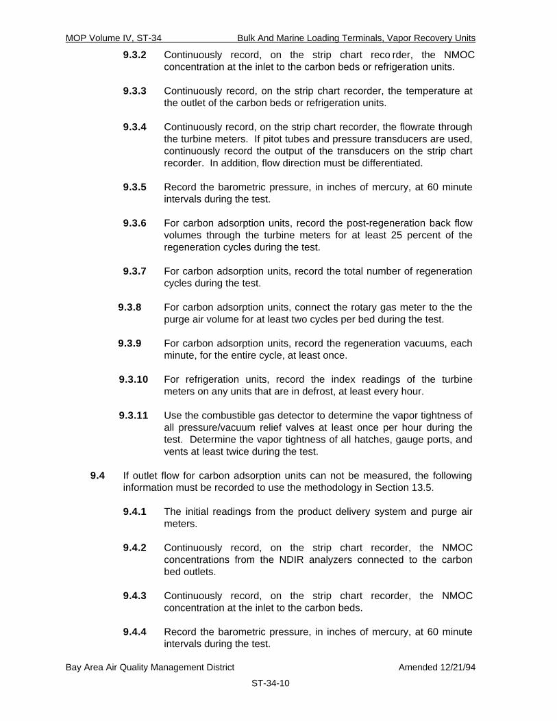
9.3.2 Continuously record, on the strip chart reco rder, the NMOCconcentration at the inlet to the carbon beds or refrigeration units.
9.3.3 Continuously record, on the strip chart recorder, the temperature atthe outlet of the carbon beds or refrigeration units.
9.3.4 Continuously record, on the strip chart recorder, the flowrate throughthe turbine meters. If pitot tubes and pressure transducers are used,continuously record the output of the transducers on the strip chartrecorder. In addition, flow direction must be differentiated.
9.3.5 Record the barometric pressure, in inches of mercury, at 60 minuteintervals during the test.
9.3.6 For carbon adsorption units, record the post-regeneration back flowvolumes through the turbine meters for at least 25 percent of theregeneration cycles during the test.
9.3.7 For carbon adsorption units, record the total number of regenerationcycles during the test.
9.3.8 For carbon adsorption units, connect the rotary gas meter to the thepurge air volume for at least two cycles per bed during the test.
9.3.9 For carbon adsorption units, record the regeneration vacuums, eachminute, for the entire cycle, at least once.
9.3.10 For refrigeration units, record the index readings of the turbinemeters on any units that are in defrost, at least every hour.
9.3.11 Use the combustible gas detector to determine the vapor tightness ofall pressure/vacuum relief valves at least once per hour during thetest. Determine the vapor tightness of all hatches, gauge ports, andvents at least twice during the test.
9.4 If outlet flow for carbon adsorption units can not be measured, the followinginformation must be recorded to use the methodology in Section 13.5.
9.4.1 The initial readings from the product delivery system and purge airmeters.
9.4.2 Continuously record, on the strip chart recorder, the NMOCconcentrations from the NDIR analyzers connected to the carbonbed outlets.
9.4.3 Continuously record, on the strip chart recorder, the NMOCconcentration at the inlet to the carbon beds.
9.4.4 Record the barometric pressure, in inches of mercury, at 60 minuteintervals during the test.

MOP Volume IV, ST-34 Bulk And Marine Loading Terminals, Vapor Recovery Units
Bay Area Air Quality Management District Amended 12/21/94
ST-34-11
9.4.5 Record the total number of regeneration cycles during the test.
9.4.6 Connect the rotary gas meter to the purge air inlet using 2.5 inch IDflexible tubing. Record the purge air volume for at least two cyclesper bed during the test. In addition, record total purge air for eachbed for the entire duration of the test.
9.4.7 For at least two regeneration cycles per carbon bed, record theregeneration vacuums each minute.
9.4.8 Record the carbon vessel volume and carbon density.
9.4.9 Use the combustible gas detector to determine the vapor tightness ofall pressure/vacuum relief valves at least once per hour during thetest. Determine the vapor tightness of all hatches, gauge ports, andvents at least twice during the test.
9.5 Use the vapor system pressure assembly to determine the system pressure ateach vapor return arm as follows:
9.5.1 Connect the assembly to vapor coupler of the delivery vehicle.
9.5.2 Zero the pressure gauge according to manufacturer'srecommendations.
9.5.3 Connect the vapor return arm to the assembly.
9.5.4 During product loading, record the maximum pressure from the gauge.
10. SAMPLING - THERMAL INCINERATION UNITS
10.1 Conduct the test for a minimum of 4 hours or 100,000 gallons throughput,whichever is greater. Insure that testing interval includes peak loading hours.
10.2 The following data shall be recorded prior to commencement of loadingoperations:
10.2.1 The initial reading from the turbine meter index from the turbinemeter mounted on the incinerator inlet line, if applicable.
10.2.2 The initial readings from the product delivery system.
10.2.3 Record the height of the Vapor Storage Tank (VST) if so equipped.The test shall begin and end at the same VST height.
10.3 During the entire duration of the test the following data acquisition proceduresshall be followed:

MOP Volume IV, ST-34 Bulk And Marine Loading Terminals, Vapor Recovery Units
Bay Area Air Quality Management District Amended 12/21/94
ST-34-12
10.3.1 Continuously record, on the strip ch art recorder, the inlethydrocarbon concentration at the inlet to the incinerator.
10.3.2 Continuously record, on the strip chart recorder, the hydrocarbon,carbon dioxide, carbon monoxide, and oxygen concentrations at theoutlet of the incinerator.
10.3.3 Continuously record, on the strip chart recorder, the temperature atthe inlet of the turbine meter.
10.3.4 Continuously record, on the strip chart recorder, the flowrate throughthe turbine meter. If pitot tubes and pressure transducers are used,continuously record the output of the transducers on the strip chartrecorder.
Figure 34-6
Incinerator Sample Probe Assembly
10.3.5 Record the barometric pressure, in inches of mercury, at 60 minuteintervals during the test.
10.3.6 Determine the methane concentration by either (a) collectingintegrated samples for laboratory analysis or (b) passing a portion ofthe sample stream through the activated carbon scrubber to adsorbNMOC prior to the analyzer.

MOP Volume IV, ST-34 Bulk And Marine Loading Terminals, Vapor Recovery Units
Bay Area Air Quality Management District Amended 12/21/94
ST-34-13
10.3.7 Record the auxiliary fuel usage, from the dry gas meter, at 60 minuteintervals during the test.
10.3.8 Use the combustible gas detector to determine the vapor tightness ofall pressure/vacuum relief valves at least once per hour during thetest. Determine the vapor tightness of all hatches, gauge ports, andvents at least twice during the test.
10.4 Use the vapor system pressure assembly to determine the system pressure ateach vapor return arm as follows:
10.4.1 Connect the assembly to vapor coupler of the delivery vehicle.
10.4.2 Zero the pressure gauge according to manufacturer'srecommendations.
10.4.3 Connect the vapor return arm to the assembly.
10.4.4 During product loading, record the maximum pressure from thegauge.
11. SAMPLING - VAPOR STORAGE TANK
11.1 Conduct the test for a minimum of 4 hours or 100,000 gallons throughput,whichever is greater. Insure that testing interval includes peak loading hours.
11.2 The following data shall be recorded prior to commencement of loadingoperations:
11.2.1 The initial readings from the index on the turbine meter.
11.2.2 The initial readings from the product delivery system.
11.2.3 The height of the VST.
11.3 During the entire duration of the test the following data acquisition proceduresshall be followed:
11.3.1 Continuously record, on the strip chart recorder, the NMOCconcentrations from the NDIR analyzer connected to the turbinemeter on the main outlet or manway of the VST.
11.3.2 Continuously record, on the strip chart recorder, the temperature atthe outlet of the main vent or manway of the VST.
11.3.3 Continuously record on the strip chart recorder the flowrate throughthe turbine meter.
11.3.4 Record the barometric pressure, in inches of mercury, at 60 minuteintervals during the test.

MOP Volume IV, ST-34 Bulk And Marine Loading Terminals, Vapor Recovery Units
Bay Area Air Quality Management District Amended 12/21/94
ST-34-14
11.3.5 Record the pressure reading at the meter during out breathing atleast 5 times during the test. If the reading exceeds the minimumpressure setting of the pressure/vacuum valve on the head space ofthe VST, immediately disconnect the meter and reopen any othervents sealed for the test and use the Alternative VST Method todetermine the emission rate from the VST.
11.3.6 Record the pressure reading at the check valve during in breathing atleast 5 times during the test. If the reading exceeds the minimumvacuum setting of the pressure/vacuum valve on the head space ofthe VST, immediately disconnect the meter and reopen any othervents sealed for the test and use the Alternative VST Method todetermine the emission rate from the VST.
Figure 34-7
Vapor System Pressure Assembly
11.3.7 Use the combustible gas detector to determine the vapor tightness ofall pressure/vacuum relief valves at least once per hour during thetest. Determine the vapor tightness of all hatches, gauge ports,vents, and temporarily sealed vents at least twice during the test.
11.4 If the VST is not equipped with a pressure/vacuum valve on the head spaceabove the bladder or if the pressures at the check valve/meter assembly

MOP Volume IV, ST-34 Bulk And Marine Loading Terminals, Vapor Recovery Units
Bay Area Air Quality Management District Amended 12/21/94
ST-34-15
exceed the pressure/vacuum valve minimum settings the following AlternativeVST Method shall be used:
11.4.1 The VST test shall begin when the bladder reaches its lowestpossible point.
11.4.2 The VST shall be isolated from the VRU so that all vapors go directlyfrom the loading rack to the VST.
11.4.3 All valving leading from the VST shall be closed so that all vaporsfrom the rack remain in the VST.
11.4.4 After each truck finishes loading, the height of the VST shall berecorded along with the total amount of product loaded.
11.4.5 After the VST has reached 50% of its capacity the valving to the VRUmay be opened and the VST may be returned into normal operation.
11.4.6 A VST height versus product loaded curve shall be generated.
11.4.7 After the VRU/VST equipment is in normal operating mode, theheights of the VST shall be collected as follows:
11.4.7.1 Each time the bladder begins to raise the height shall berecorded.
11.4.7.2 Each time the bladder begins to drop the height shall berecorded.
12. POST-TEST PROCEDURES
12.1 At the conclusion of the test the following shall be recorded:
12.1.1 The final turbine meter index reading(s).
12.1.2 The final product meter readings.
12.1.3 The height of the VST, if so equipped. This height shall be the sameas it was at the beginning of the test.
12.2 Record the final dry test meter readings on the auxiliary fuel line forIncineration Units.
13. CALCULATIONS - CARBON ADSORPTION AND REFRIGERATION UNITS
13.1 The outlet volume from each carbon bed shall be calculated as follows:
( ) ( )
VVT
V NT
Pes
m
m
b
a
b=
+
53029 92.
[Equation 13-1]

MOP Volume IV, ST-34 Bulk And Marine Loading Terminals, Vapor Recovery Units
Bay Area Air Quality Management District Amended 12/21/94
ST-34-16
where:
Ves = Outlet gas volume from the VRU, standard cubic feetVm = The uncorrected volume from the turbine meter, actual cubic feetTm = Average temperature through the turbine meter, oRVb = The average post regeneration back flow through the turbine meter,
actual cubic feetN = The number of post regeneration back flows during the testTa = Average ambient temperature during post-re generation back flows,
oRPb = The average barometric pressure during the test, inches of mercury530 = Standard temperature, oR29.92 = Standard barometric pressure, inches of mercury
13.1.2 For those tests where a pitot tube and pressure transducer are usedthe Carbon Adsorption VRU outlet volume shall be calculated asfollows:
( )( )( ) ( )( )( )( )( ) ( )
( )( )V t C A pP
T MWep t p AVGs
s
=
. .
.81 60 85 49
53029 92
12
12
∆ [Equation 13-2]
where:
Vep = Outlet gas volume from the VRU, standard cubic feettt = The total test time, minutesA = The outlet duct cross-sectional area, square feetCp = The pitot tube coefficient, dimensionless∆p = The velocity head, inches of waterTs = The average temperature of the outlet gas stream, oRPs = The absolute stack gas pressure, inches of mercuryMW = Average molecular weight of the outlet gas, pound per pound-mole0.81 = Correction factor for pitot tube at duct centerline, dimensionless60 = Conversion from seconds to minutes, seconds per minute85.49 = Conversion Factor derived from Bernoulli 's Equation and standard
conditions530 = Standard temperature, oR29.92 = Standard barometric pressure, inches of mercury
NOTE: ∆p AVG
12 requires the arithmetic average of the square roots of the
velocity heads. Only outflow shall be used in this calculation.
13.1.3 The outlet volume for refrigeration units shall be calculated as follows:
[ ][ ][ ][ ][ ]V
V V PTrs
m c b
m
=+ 530
29 92.[Equation 13-3]
where:

MOP Volume IV, ST-34 Bulk And Marine Loading Terminals, Vapor Recovery Units
Bay Area Air Quality Management District Amended 12/21/94
ST-34-17
Vrs = Outlet gas volume from the VRU, standard cubic feetVm = The uncorrected volume from the turbine meter, actual cubic feetVc = The uncorrected back flow volume measured during unit defrost,
actual cubic feetPb = The average barometric pressure during the test, inches of mercuryTm = Average temperature through the turbine meter, oR530 = Standard temperature, oR29.92 = Standard barometric pressure, inches of mercury
13.2 The weight of non-methane organic carbon (NMOC) emitted during the testshall be calculated as follows:
[ ][ ][ ][ ][ ]
WV HC MW
ss es=386 9 100.
[Equation 13-4]
where:
Ws = The weight of NMOC emitted from each carbon bed during the test,pounds
Vs = Outlet gas volume from each carbon bed, using Equation 13-1, 13-2or 13-3, standard cubic feet
HCes = The average outlet concentration from each carbon bed orrefrigeration unit, % NMOC
MW = The molecular weight of the span gas used, pounds per pound-mole386.9 = The molar volume, cubic feet per pound-mole100 = The conversion factor from decimal fraction to percent
13.3 For those tests where a turbine meter is used at the inlet to the carbon orrefrigeration unit, the inlet volume shall be calculated as follows:
[ ][ ][ ][ ][ ]V
VT P Pis
m
m b s
=+
530 29 92.[Equation 13-5]
where:
Vis = Inlet gas volume to the VRU, standard cubic feetVm = The uncorrected volume from the turbine meter, actual cubic feetTm = Average temperature through the turbine meter, oRPb = The average barometric pressure during the test, inches of mercuryPs = The average static pressure at the turbine meter, inches of mercury530 = Standard temperature, oR29.92 = Standard barometric pressure, inches of mercury
13.3.1 For those tests where a pitot tube and pressure transducer are used atthe inlet to the carbon or refrigeration unit, the inlet volume shall becalculated as follows:

MOP Volume IV, ST-34 Bulk And Marine Loading Terminals, Vapor Recovery Units
Bay Area Air Quality Management District Amended 12/21/94
ST-34-18
( )( )( ) ( )( )( )( )( ) ( )
( )( )V t C A pP
T MWip t p AVGs
s
=
. .
.81 60 85 49
53029 92
12
12
∆ [Equation 13-6]
where:
Vip = Inlet gas volume from the VRU, standard cubic feettt = The total test time, minutesA = The inlet duct cross-sectional area, square feetCp = The pitot tube coefficient, dimensionless∆p = The velocity head, inches of waterTs = The average temperature of the inlet gas stream, oRPs = The absolute stack gas pressure, inches of mercuryMW = Average molecular weight of the inlet gas, pound per pound-mole0.81 = Correction factor for pitot tube at duct centerline, dimensionless60 = Conversion from seconds to minutes, seconds per minute85.49 = Conversion Factor derived from Bernoulli's Equation and standard
conditions530 = Standard temperature, oR29.92 = Standard barometric pressure, inches of mer cury
NOTE: ∆p AVG
12 requires the arithmetic average of the square roots of the
velocity heads.
13.3.2 When the inlet volume can not be measured using a turbine meter orpitot tube, the inlet volume of NMOC entering the carbon adsorption orrefrigeration unit during the test shall be calculated as follows:
[ ][ ][ ][ ][ ][ ]VG P PTis
b m
is
=+530
7 481 29 92. .[Equation 13-7]
where:
Vis = The volume entering the carbon adsorption unit, poundsG = The number of gallons of product loaded, gallonsPb = The barometric pressure, inches of mercuryPm = The static inlet line pressure, inches of mercuryTis = The average inlet temperature, oR530 = Standard temperature, oR7.481 = The conversion factor from gallons to cubic feet, gallons per cubic
foot
13.4 The weight of non-methane organic carbon (NMOC) entering the carbonadsorption or refrigeration unit during the test shall be calculated as follows:
[ ][ ][ ][ ][ ]WV HC MW
ii i=386 9 100.
[Equation 13-8]

MOP Volume IV, ST-34 Bulk And Marine Loading Terminals, Vapor Recovery Units
Bay Area Air Quality Management District Amended 12/21/94
ST-34-19
where:
Wi = The weight of NMOC entering each carbon or refrigeration unit,pounds
Vi = Inlet gas volume to each carbon bed or refrigeration unit, usingEquation 13-5, 13-6 or 13-7, standard cubic feet
HCi = The average inlet concentration from the carbon adsorption orrefrigeration system, % NMOC
MW = The molecular weight of the span gas used, pounds per pound-mole
386.9 = The molar volume, cubic feet per pound-mole100 = The conversion factor from decimal fraction to percent
13.5 In the event that the outlet flow can not be measured, the following methodmust be utilized. The outlet volume from the carbon beds shall be calculatedas follows:
V Vregen bedcarbon
carbon
= −
#ρ
[Equation 13-9]
where:
Vregen = The regeneration volume of the carbon bed, cubic feetVbed = The volume of the carbon vessel, cubic feet#carbon = The total amount of carbon in the vessel, poundsρcarbon = The density of carbon used, pound per cubic foot
( )( ) ( )( )( )( )( )V
V P
PV
N PT
Vasregen regen
bpurge
Opposite
b
ai1
53029 92
= +
×
+
. [Equation 13-10]
where:
Vas1= The outlet volume from Bed 1, cubic feet
Pregen = The maximum vacuum reached during regeneration of theopposite Bed, inches of mercury
Vpurge = The average purge air volume, cubic feetPb = The average barometric pressure, inches of mercuryTa = The average ambient temperature, oRVi = The total inlet volume, using Equation 13-7, standard cubic feetN = The total number of cycles530 = Standard temperature, oR
13.5.1 The outlet weight of NMOC for each carbon bed shall be calculatedusing Equation 13-4.
13.6 The emission factor for carbon adsorption and re frigeration units shall becalculated as follows:

MOP Volume IV, ST-34 Bulk And Marine Loading Terminals, Vapor Recovery Units
Bay Area Air Quality Management District Amended 12/21/94
ST-34-20
[ ][ ] [ ]E
W W
Geses es=
+×1 2 1000 [Equation 13-11]
where:
Ees = The total emission factor, pounds per 1,000 gallon loaded
Wes1= The total outlet weight from unit 1 using Equation 13-4, pounds
Wes2= The total outlet weight from unit 2 using Equation 13-4, pounds
G = The total number of gallons of product loaded, gallons
13.6.1 The efficiency of the carbon adsorption or refrigeration units shall becalculated as follows:
[ ][ ] [ ]H
W W W
Wi es es
i
=− +
×1 2 100 [Equation 13-12]
where:
H = The efficiency, by weight, of the carbon adsorption unit, percent
Wi = The total inlet weight of NMOC using Equations 13-8, pounds
Wes1= The total outlet weight from unit 1, using Equation 13-4, pounds
Wes2= The total outlet weight from unit 2, using Equation 13-4, pounds
100 = The conversion factor from decimal fraction to percent
14. Calculations-Thermal Incineration
14.1 The incinerator inlet volume shall be calcu lated as follows :
14.1.1 For those tests where a turbine meter is be used the incinerator inletvolume shall be calculated as follows :
[ ][ ][ ][ ][ ]V
VT P Pis
m
m b s
=+
530 29 92.[Equation 14-1]
where:
Vis = Inlet gas volume to the VRU, standard cubic feetVm = The uncorrected volume from the turbine meter, actual cubic feetTm = Average temperature through the turbine meter, oRPb = The average barometric pressure during the test, inches of mercuryPs = The average static pressure at the turbine meter, inches of m ercury530 = Standard temperature, oR29.92 = Standard barometric pressure, inches of mercury
14.1.2 For those tests where a pitot tube and pressure transducer are usedthe incinerator inlet volume shall be calculated as follows:

MOP Volume IV, ST-34 Bulk And Marine Loading Terminals, Vapor Recovery Units
Bay Area Air Quality Management District Amended 12/21/94
ST-34-21
( )( )( ) ( )( )( )( )( ) ( )
( )( )V t C A pP
T MWip t p AVGs
s
=
. ..
81 60 85 49530
29 92
12
12
∆ [Equation 14-2]
where:
Vip = Inlet gas volume from the VRU, standard cubic feettt = The total test time, minutesA = The inlet duct cross-sectional area, square feetCp = The pitot tube coefficient, dimensionless∆p = The velocity head, inches of waterTs = The average temperature of the inlet gas stream, oRPs = The absolute stack gas pressure, inches of mercuryMW = Average molecular weight of the inlet gas, pound per pound-mole0.81 = Correction factor for pitot tube at duct centerline, dimensionless60 = Conversion from seconds to minutes, seconds per minute85.49 = Conversion Factor derived from Bernoulli's Equation and standard
conditions530 = Standard temperature, oR29.92 = Standard barometric pressure , inches of mercury
NOTE: ∆p AVG
12 requires the arithmetic average of the square roots of the
velocity heads.
14.2 The outlet volume from the thermal incinerator shall be calculated as follows:
( )( )[ ]( )( ) ( ) ( )[ ]V
V k HC
k HC CO COesis i
e e e
=+ + −2 300
[Equation 14-3]
where:
Ves = The exhaust gas volume, standard cubic feetVis = The inlet gas volume to the incinerator, using Equations 14-1 or 14-
2, standard cubic feetk = The calibration gas factor, 3 = Propane, 4 = ButaneHCi = The average inlet hydrocarbon concent ration, ppmvHCe = The average outlet hydrocarbon concentration, ppmvCO2e = The average outlet carbon dioxide concentration, ppmvCOe = The average outlet carbon monoxide concentration, ppmv300 = The ambient carbon dioxide concentration, ppmv
Note: If a more accurate ambient concentration can be measured, it may besubstituted for the 300 ppmv used in the above equation.
14.3 The weight of non-methane organic carbon (NMOC) emitted during the testshall be calculated as follows:

MOP Volume IV, ST-34 Bulk And Marine Loading Terminals, Vapor Recovery Units
Bay Area Air Quality Management District Amended 12/21/94
ST-34-22
[ ][ ][ ][ ][ ]WV HC MW
eses es=
×386 9 1 106.[Equation 14-4]
where:
Wes = The weight of NMOC emitted from the incinerator during the test,pounds
Ves = The exhaust gas volume to the incinerator, using Equation 14-3,standard cubic feet
HCes = The average outlet concentration from the incinerator, NMOC,ppmv
MW = The molecular weight of the span gas used, pounds per pound-mole
386.9 = The molar volume, cubic feet per pound-mole106 = The conversion factor from decimal fraction to percent
14.4 The inlet weight of NMOC entering the inciner ator during the test shall becalculated using Equations 14-5 or 14-6.
14.4.1 If actual inlet flow measurements cannot be obtained, the inlet weightshall be calculated as follows:
[ ][ ][ ][ ][ ][ ][ ][ ]
[ ][ ][ ][ ][ ][ ][ ]W
G HC MWT
V HC MWTis
is
is
aux ai
ai
= +530
7 481 386 9 100530
386 9 100. . .[Equation 14-5]
where:
Wis = The weight of NMOC entering the carbon adsorption unit, poundsG = The number of gallons of product loaded, gallonsHCis = The average inlet concentration, % NMOCTis = The average inlet gas stream temperature, oRVaux = The volume of auxiliary gas introduced before the incinerator, cubic
feetHCai = The average auxiliary gas concentration, %Tai = The average auxiliary gas temperature, oRMW = The molecular weight of the span gas used, pounds per pound-
mole530 = Standard temperature, oR7.481 = The conversion factor from gallons to cubic feet, gallons per cubic
foot386.9 = The molar volume, cubic feet per pound-mole100 = The conversion factor from decimal fraction to percent
14.4.2 If a pitot tube and pressure transducer or a turbine meter was used,the inlet weight shall be calculated as follows:

MOP Volume IV, ST-34 Bulk And Marine Loading Terminals, Vapor Recovery Units
Bay Area Air Quality Management District Amended 12/21/94
ST-34-23
[ ][ ][ ][ ][ ]W
V HC MWip
ip is=386 9 100.
[Equation 14-6]
where:
Wip = The weight of NMOC entering the VRU, poundsVip = Inlet gas volume calculated using Equations 14-1 or 14-2, standard
cubic feetHCis = The average inlet concentration, % NMOCMW = The molecular weight of the span gas used, pounds per pound-
mole386.9 = The molar volume, cubic feet per pound-mole100 = The conversion factor from decimal fraction to percent
14.5 The emission factor for the incinerator shall be calculated as follows:
[ ][ ] [ ]EWGes
es= × 1000 [Equation 14-7]
where:
Ees = The total emission factor, pounds per 1,000 gallons loadedWes = The total outlet weight during the test, using Equation 14-4, poundsG = The total number of barrels of product loaded, gallons
14.6 The efficiency of the incinerator shall be calculated as follows:
[ ] [ ][ ] [ ]H
W WW
i es
i
=−
× 100 [Equation 14-8]
where:
H = The efficiency, by weight, of the incinerator, percentWi = The total inlet weight using Equations 14-5 or 14-6, pounds
Wes = The total outlet weight using Equation 14-4, pounds100 = The conversion factor from decimal fraction to percent
15. Calculations - Vapor Storage Tank
15.1 The outlet volume from the VST shall be calculated as follows :
[ ][ ][ ][ ][ ]V
VT P Pot
m
m b s
=+
530 29 92.[Equation 15-1]
where:
MOP Volume IV, ST-34 Bulk And Marine Loading Terminals, Vapor Recovery Units
Bay Area Air Quality Management District Amended 12/21/94
ST-34-24
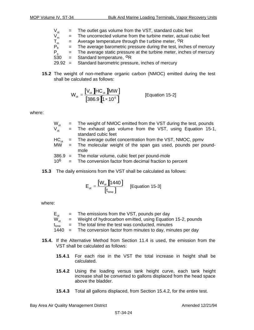
Vot = The outlet gas volume from the VST, standard cubic feetVm = The uncorrected volume from the turbine meter, actual cubic feetTm = Average temperature through the t urbine meter, oRPb = The average barometric pressure during the test, inches of mercuryPs = The average static pressure at the turbine meter, inches of mercury530 = Standard temperature, oR29.92 = Standard barometric pressure, inches of mercury
15.2 The weight of non-methane organic carbon (NMOC) emitted during the testshall be calculated as follows:
[ ][ ][ ][ ][ ]WV HC MW
otot ot=
×386 9 1 106.[Equation 15-2]
where:
Wot = The weight of NMOC emitted from the VST during the test, poundsVot = The exhaust gas volume from the VST, using Equation 15-1,
standard cubic feetHCot = The average outlet concentration from the VST, NMOC, ppmvMW = The molecular weight of the span gas used, pounds per pound-
mole386.9 = The molar volume, cubic feet per pound-mole106 = The conversion factor from decimal fraction to percent
15.3 The daily emissions from the VST shall be calculated as follows:
[ ][ ][ ]E
Wtot
ot
time
=1440
[Equation 15-3]
where:
Eot = The emissions from the VST, pounds per dayWot = Weight of hydrocarbon emitted, using Equation 15-2, poundsttime = The total time the test was conducted, minutes1440 = The conversion factor from minutes to day, minutes per day
15.4. If the Alternative Method from Section 11.4 is used, the emission from theVST shall be calculated as follows:
15.4.1 For each rise in the VST the total increase in height shall becalculated.
15.4.2 Using the loading versus tank height curve, each tank heightincrease shall be converted to gallons displaced from the head spaceabove the bladder.
15.4.3 Total all gallons displaced, from Section 15.4.2, for the entire test.

MOP Volume IV, ST-34 Bulk And Marine Loading Terminals, Vapor Recovery Units
Bay Area Air Quality Management District Amended 12/21/94
ST-34-25
15.4.4 The total weight of NMOC emitted from the VST shall be calculatedas follows:
[ ][ ][ ][ ][ ][ ][ ][ ][ ][ ]
WG HC MW P
Totdis ot b
a
=×
530
7 481 386 9 1 10 29 926. . .[Equation 15-4]
where:
Wot = The weight of NMOC emitted from the VST during the test, poundsGdis = The total gallons displaced by the bladder from Section 15.4.3,
gallonsHCot = The average outlet concentration from the VST, NMOC, ppmvMW = The molecular weight of the span gas used, pounds per pou nd-
molePb = The average barometric pressure during the test, inches of mercuryTa = The average ambient temperature during the test, oR7.481 = The conversion from gallons to cubic feet, gallons per cubic foot386.9 = The molar constant, cubic feet per pound-mole106 = The conversion factor from decimal fraction29.92 = Standard barometric pressure, inches of mercury
16. Reporting
16.1 The results of a test on a carbon adsorption unit shall be reported as shown inForm 34-1. The results of a test on a refrigeration unit shall be reported asshown in Form 34-2. The results of a test on a thermal incineration unit shallbe reported as shown in Form 34-3. The results of a test on a vapor storagetank shall be reported as shown in Form 34-4.

Form 34-1
ST-34-26
Distribution:FirmPermit ServicesEnforcement ServicesTechnical ServicesPlanningRequesterDAPCO
BAY AREAAIR QUALITY MANAGEMENT DISTRICT
939 Ellis StreetSan Francisco, California 94109
(415) 771-6000
Summary ofSource Test Results
Report No.:
Test Date:
Test Times:
Run A:
Run B:
Run C:
Source Information BAAQMD RepresentativesFirm Name and Address Firm Representative and Title
Phone No. ( )
Source Test Engineers
Permit Conditions: Source: Permit Services Division/EnforcementDivision
Plant No. Permit No. Test Requested By:Operates Hr/Day & Day/Yr
Operating Parameters: Organic Liquid Loaded During Test, Gallons: Gasoline: Diesel: AV Gas: Jet A: Other: Total:Applicable Regulations: VN Recommended:
Sources Test Results and Comments:PARAMETER RESULTS
LIMITSBed #1 Bed #2 System
Inlet Volume, SCFPurge Air, avg per cycle, SCFBackflow, avg per cycle, SCFNumber of Cycles, totalInlet NMOC Concentration, %, avg. as C4Inlet NMOC Weight, pounds
Outlet Volume, SCFOutlet NMOC Concentration, ppmv , avg. as C4Outlet Weight, poundsEmission Factor, pounds per 1,000 gallonsEfficiency, weight percentMaximum System Pressure, Inches H2OIF THE METHODOLOGY IN SECTION 13.5 IS USED THE FOLLOWING INFORMATION SHALL ALSO BE INCLUDED:Cabon Bed Vessel Volume, cubic feetCarbon Density, lbs per cubic foot
Air Quality Engineer II Date Supervising Air Quality Engineer Date Approved by Air Quality EngineeringManager
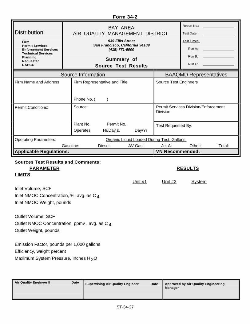
Form 34-2
ST-34-27
Distribution:FirmPermit ServicesEnforcement ServicesTechnical ServicesPlanningRequesterDAPCO
BAY AREAAIR QUALITY MANAGEMENT DISTRICT
939 Ellis StreetSan Francisco, California 94109
(415) 771-6000
Summary ofSource Test Results
Report No.:
Test Date:
Test Times:
Run A:
Run B:
Run C:
Source Information BAAQMD RepresentativesFirm Name and Address Firm Representative and Title
Phone No. ( )
Source Test Engineers
Permit Conditions: Source: Permit Services Division/EnforcementDivision
Plant No. Permit No. Test Requested By:Operates Hr/Day & Day/Yr
Operating Parameters: Organic Liquid Loaded During Test, Gallons: Gasoline: Diesel: AV Gas: Jet A: Other: Total:Applicable Regulations: VN Recommended:
Sources Test Results and Comments:PARAMETER RESULTS
LIMITSUnit #1 Unit #2 System
Inlet Volume, SCFInlet NMOC Concentration, %, avg. as C 4Inlet NMOC Weight, pounds
Outlet Volume, SCFOutlet NMOC Concentration, ppmv , avg. as C 4Outlet Weight, pounds
Emission Factor, pounds per 1,000 gallonsEfficiency, weight percentMaximum System Pressure, Inches H 2O
Air Quality Engineer II Date Supervising Air Quality Engineer Date Approved by Air Quality EngineeringManager

Form 34-3
ST-34-28
Distribution:FirmPermit ServicesEnforcement ServicesTechnical ServicesPlanningRequesterDAPCO
BAY AREAAIR QUALITY MANAGEMENT DISTRICT
939 Ellis StreetSan Francisco, California 94109
(415) 771-6000
Summary ofSource Test Results
Report No.:
Test Date:
Test Times:
Run A:
Run B:
Run C:
Source Information BAAQMD RepresentativesFirm Name and Address Firm Representative and Title
Phone No. ( )
Source Test Engineers
Permit Conditions: Source: Permit Services Division/EnforcementDivision
Plant No. Permit No. Test Requested By:Operates Hr/Day & Day/Yr
Operating Parameters: Organic Liquid Loaded During Test, Gallons: Gasoline: Diesel: AV Gas: Jet A: Other: Total:Applicable Regulations: VN Recommended:
Sources Test Results and Comments:PARAMETER RESULTS
LIMITSInlet Volume to Incinerator, SCFInlet Volume, Auxillary Fuel, SCFInlet NMOC Concentration, %, avg. as C 4Inlet NMOC Weight, pounds
Outlet Hydrocarbon Concentration, ppmv , avg. as C 3Outlet Methane Concentration, ppmv, avg. as C 1Outlet CO Concentration, ppmv, avg.Outlet CO2 Concentration, %, avg.Outlet Volume, SCF
NMOC as C3 CO CO2Outlet Weight, poundsEmission Factor, pounds per 1,000 gallonsEfficiency, weight percentMaximum System Pressure, Inches H 2O
Air Quality Engineer II Date Supervising Air Quality Engineer Date Approved by Air Quality EngineeringManager

Form 34-4
ST-34-29
Distribution:FirmPermit ServicesEnforcement ServicesTechnical ServicesPlanningRequesterDAPCO
BAY AREAAIR QUALITY MANAGEMENT DISTRICT
939 Ellis StreetSan Francisco, California 94109
(415) 771-6000
Summary ofSource Test Results
Report No.:
Test Date:
Test Times:
Run A:
Run B:
Run C:
Source Information BAAQMD RepresentativesFirm Name and Address Firm Representative and Title
Phone No. ( )
Source Test Engineers
Permit Conditions: Source: Permit Services Division/EnforcementDivision
Plant No. Permit No. Test Requested By:Operates Hr/Day & Day/Yr
Operating Parameters: Organic Liquid Loaded During Test, Gallons: Gasoline: Diesel: AV Gas: Jet A: Other: Total:Applicable Regulations: VN Recommended:
Sources Test Results and Comments:PARAMETER RESULTS
LIMITS
VST Outlet Volume, SCFVST Outlet NMOC Concentration, ppmv, avg. as C 1
VST Test Time, total minutesVST Outlet NMOC Weight, poundsVST Emission Factor, pounds per day
Air Quality Engineer II Date Supervising Air Quality Engineer Date Approved by Air Quality EngineeringManager