DRB-25 Digital Repeater and Base Stationwestelwireless.com/downloads/WWSMA00400_100.pdfWESTEL...
144
WESTEL WIRELESS SYSTEMS WWS–MA–00400 Issue 1.00 (USA) i DRB-25 Digital Repeater and Base Station Installation and Operator Handbook Document No.: WWS-MA-00400 Current Issue: 1.00 (USA) Date: 31 Aug 2011 Website: www.westelwireless.com Contact: [email protected]
Transcript of DRB-25 Digital Repeater and Base Stationwestelwireless.com/downloads/WWSMA00400_100.pdfWESTEL...
WESTEL WIRELESS SYSTEMS
WWS–MA–00400 Issue 1.00 (USA) i
DRB-25
Digital Repeater and Base Station
Installation and
Operator Handbook
Document No.: WWS-MA-00400
Current Issue: 1.00 (USA)
Date: 31 Aug 2011 Website: www.westelwireless.com Contact: [email protected]

WESTEL WIRELESS SYSTEMS
WWS–MA–00400 Issue 1.00 (USA) ii
As part of its ongoing commitment to product improvement, Westel Wireless Systems reserves the right to alter at any time the equipment and specifications described in this publication. All performance figures quoted are typical and are subject to normal manufacturing and service tolerances. The purchaser is warned that the statements made in this publication may be inaccurate due to typographical or other errors or subsequent modification of the products described herein. Whilst every care has been taken in the preparation of this publication, no warranty of accuracy or reliability is given in relation to any advice or information contained in this publication and no responsibility for any loss or damage whatsoever arising in any way for any representation, act or omission whether express or implied (including responsibility to any person by reasons of negligence) is accepted by Westel Wireless Systems or any officer, agent, or employee of it.
© Westel Wireless Systems, 2000 - 2011. This work is copyright. Other than as permitted by law, no part of it may be reproduced, stored in a retrieval system or transmitted in any form or by any process without prior written permission. This device made under license under one or more of the following US patents: 5,164,986; 5,146,497; 5,185,795, 4,636,791; 4,590,473; 5,185,796; 5,148,482; 5,271,017; 5,377,229; 4,833,701; 4,972,460; 5,651,030. Other worldwide patents pending. The IMBETM voice coding technology embodied in this product is protected by intellectual property rights including patent rights, copyrights and trade secrets of Digital Voice Systems, Inc. The voice coding technology can be used only as part of the North American land mobile communications system for APCO Project 25. The user of this technology is explicitly prohibited from attempting to decompile, reverse engineer, or disassemble the Object Code, or in any other way convert the Object Code into a human readable form.

WESTEL WIRELESS SYSTEMS
WWS–MA–00400 Issue 1.00 (USA) iii
PREFACE This manual provides the information personnel will need to install and operate the DRB-25 Dual Channel Radio Base Station.
The manual consists of nine documents, as described below:
Title Document Ref Issue Date
Preliminary Pages WWS-MA-00400 1.00 31 Aug 2011
1 Introduction WWS-MA-00651 0.07 31 Aug 2011
2 Equipment Description WWS-MA-00652 0.06 31 Aug 2011
3 Installation Instructions WWS-MA-00653 0.09 31 Aug 2011
4 Operating Instructions WWS-MA-00654 0.05 31 Aug 2011
5 Programming and Configuration WWS-MA-00657 1.06 31 Aug 2011
6 PC Console WWS-MA-00655 1.01 31 Aug 2011
7 Diagnostics Monitor WWS-MA-00656 0.04 31 Aug 2011
Appendix A Box ID and Transceiver Default Channel Settings WWS-MA-00658 0.04 31 Aug 2011
Appendix B Module Error Codes and Recommended Actions WWS-MA-00659 0.04 31 Aug 2011
Appendix C Additional User Information WWS-MA-00670 0.01 31 Aug 2011
Definitions of warnings, cautions and notes are shown on the next page. Safety of personnel and equipment depends upon adherence to these precautions.
FCC Interference Warning This device complies with Part 15 of the FCC rules. Operation is subject to the condition that this device does not cause harmful interference.
For specific instructions regarding antenna safety and safe operating distances see Chapter 3.

WESTEL WIRELESS SYSTEMS
WWS–MA–00400 Issue 1.00 (USA) iv
PRECAUTIONARY NOTATIONS Where it is necessary to highlight a potentially hazardous situation, a critical procedure or requirement, or an important fact, the appropriate precautionary notation is used:
WARNING
A WARNING PRECEDES A PRACTICE OR PROCEDURE WHICH, IF NOT CORRECTLY FOLLOWED, COULD RESULT IN PERSONAL INJURY OR LOSS OF LIFE.
A caution precedes a practice or procedure which, if not strictly observed, could result in damage to or destruction of the equipment, or corruption of data.
ATTE NTIONOBSERVE
PRECAUTIONSF OR HANDLINGELECTROSTATIC
SENSITIVEDEVICES
A caution for static devices precedes a practice or procedure which, if not strictly observed, could result in damage to or destruction of the equipment, or corruption of data.
NOTE
A note either precedes or follows a practice, procedure or condition which requires highlighting.

WESTEL WIRELESS SYSTEMS
WWS–MA–00400 Issue 1.00 (USA) v
LIST OF ABBREVIATIONS AC Alternating Current APCO Association of Public-Safety Communications Officials - International, Inc. BER Bit Error Rate CAI Common Air Interface CM Controller Module CDCSS Continuous Digital Carrier Squelch System Comms Communications CTCSS Continuous Tone Carrier Squelch System DC Direct Current DMR Digital Mobile Radio DTMF Dual Tone Multiple Frequency EMC Electromagnetic Compatibility EMI Electromagnetic Interference IAC Interface Adapter Card IM Interface Module kHz Kilohertz LCD Liquid Crystal Display LED Light Emitting Diode MHz Megahertz PAM Power Amplifier Module PA PSM Power Amplifier Power Supply Module PABX Private Automatic Branch Exchange PBX Private Branch Exchange PC Personal Computer PCA Printed Circuit Assembly PSTN Public Switched Telephone Network PTT Press-to-talk RF Radio Frequency RU Rack Unit Rx Receive TM Transceiver Module TMP Transceiver Module Programmer Tx Transmit UHF Ultra High Frequency V Volt VHF Very High Frequency W Watt

WESTEL WIRELESS SYSTEMS
WWS–MA–00400 Issue 1.00 (USA) vi
This page left blank intentionally.

Installation and Operator Handbook Introduction
WWS–MA–00651 Issue 0.07 (USA) 1
TABLE OF CONTENTS
Page
1 INTRODUCTION
1.1 OVERVIEW............................................................................................................................................. 3 1.2 PHYSICAL ARRANGEMENT...................................................................................................................... 5
1.2.1 General ........................................................................................................................................ 5 1.2.2 Configuration Options .................................................................................................................. 6
1.3 SPECIFICATIONS.................................................................................................................................... 8 1.3.1 General Specifications ................................................................................................................. 8 1.3.2 Power Consumption..................................................................................................................... 8 1.3.3 Environmental Specifications....................................................................................................... 8 1.3.4 Applicable Standards ................................................................................................................... 9
LIST OF FIGURES FIGURE 1-1 FRONT VIEW - DRB-25........................................................................................................... 3 FIGURE 1-2 REAR VIEW - DRB-25............................................................................................................. 4 FIGURE 1-3 BLOCK DIAGRAM - DRB-25..................................................................................................... 5
LIST OF TABLES
TABLE 1-1 DRB-25 OPERATIONAL CONFIGURATIONS..................................................................................7 TABLE 1-1A DRB-25 CONTROLLER MODULE AND REPEATER MODULE FUNCTIONALITY ..................................7 TABLE 1-2 DRB-25 VOICE INTERCONNECT CONFIGURATION OPTIONS .........................................................7 TABLE 1-3 DRB-25 PROGRAMMING AND DIAGNOSTIC CONFIGURATION OPTIONS .........................................7 TABLE 1-4 GENERAL SPECIFICATIONS.........................................................................................................8 TABLE 1-5 DC POWER CONSUMPTION @ 13.8V.........................................................................................9 TABLE 1-6 ENVIRONMENTAL SPECIFICATIONS............................................................................................10 TABLE 1-7 APPLICABLE STANDARDS ...........................................................................................................9

Installation and Operator Handbook Introduction
WWS–MA–00651 Issue 0.07 (USA) 2
This page left blank intentionally.

Installation and Operator Handbook Introduction
WWS–MA–00651 Issue 0.07 (USA) 3
1 INTRODUCTION
1.1 OVERVIEW
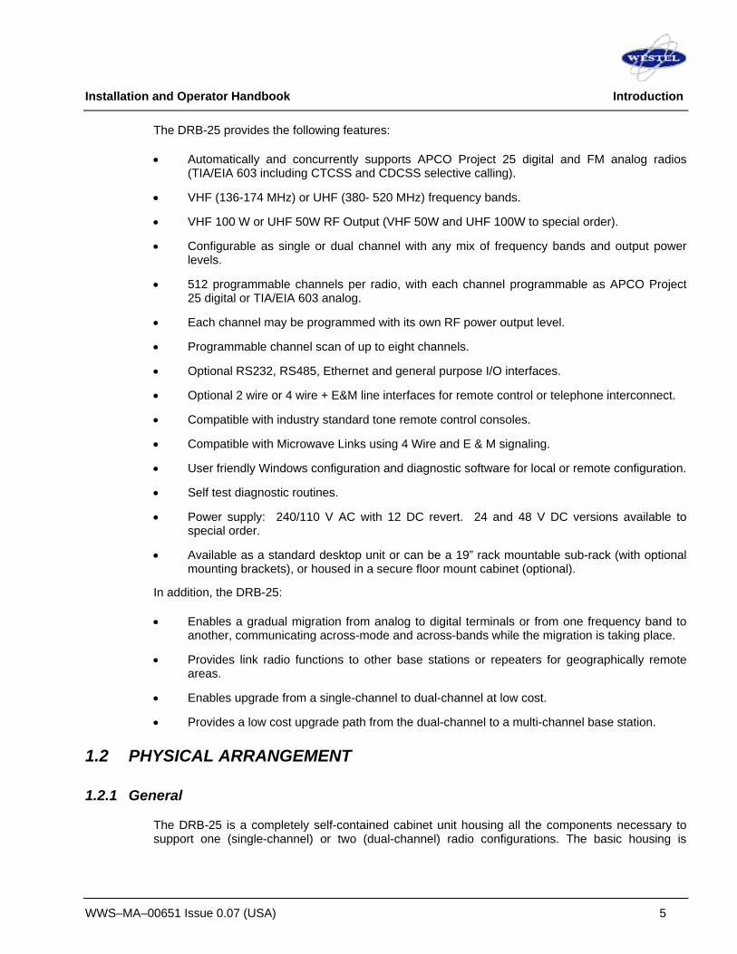
This document describes the DRB-25 Dual Radio Base Station system installation procedures, configuration and operational details.
The DRB-25, shown in Figure 1-1 and Figure 1-2, is a compact, multi-mode transceiver package that provides users with one or two analog or APCO Project 25 digital radio channels. The small size and high level of flexibility of the DRB-25 make it an ideal solution for any organization starting out on the digital migration path.
Figure 1-1 Front View - DRB-25

Installation and Operator Handbook Introduction
WWS–MA–00651 Issue 0.07 (USA) 4
Figure 1-2 Rear View - DRB-25
The DRB-25 provides one or two independent radios in a single package. Each radio may be VHF or UHF, can be used as a base station or a repeater, and may be configured to support both APCO Project 25 compliant digital subscribers as well as providing backwards compatibility to analog users. This means that existing mobile radio equipment need not be immediately retired.
Each radio may be configured to provide an analog interface (2 wire with loop or ground start or 4 wire with E & M signaling) to the public switched telephone network (PSTN), to a private branch exchange (PBX), or to existing tone based remote control units.
The DRB-25 provides the key elements of an APCO Project 25 RF Sub-system including the air interface (Um), interfaces for telephone and PBX interconnect (Et),host data systems (Ed) and Ethernet based VOIP and network management. Digital consoles and the APCO Project 25 fixed station interface (Ef) will be available as future software upgrades.
Installation and Operator Handbook Introduction
WWS–MA–00651 Issue 0.07 (USA) 5
The DRB-25 provides the following features:
• Automatically and concurrently supports APCO Project 25 digital and FM analog radios (TIA/EIA 603 including CTCSS and CDCSS selective calling).
• VHF (136-174 MHz) or UHF (380- 520 MHz) frequency bands.
• VHF 100 W or UHF 50W RF Output (VHF 50W and UHF 100W to special order).
• Configurable as single or dual channel with any mix of frequency bands and output power levels.
• 512 programmable channels per radio, with each channel programmable as APCO Project 25 digital or TIA/EIA 603 analog.
• Each channel may be programmed with its own RF power output level.
• Programmable channel scan of up to eight channels.
• Optional RS232, RS485, Ethernet and general purpose I/O interfaces.
• Optional 2 wire or 4 wire + E&M line interfaces for remote control or telephone interconnect.
• Compatible with industry standard tone remote control consoles.
• Compatible with Microwave Links using 4 Wire and E & M signaling.
• User friendly Windows configuration and diagnostic software for local or remote configuration.
• Self test diagnostic routines.
• Power supply: 240/110 V AC with 12 DC revert. 24 and 48 V DC versions available to special order.
• Available as a standard desktop unit or can be a 19” rack mountable sub-rack (with optional mounting brackets), or housed in a secure floor mount cabinet (optional).
In addition, the DRB-25:
• Enables a gradual migration from analog to digital terminals or from one frequency band to another, communicating across-mode and across-bands while the migration is taking place.
• Provides link radio functions to other base stations or repeaters for geographically remote areas.
• Enables upgrade from a single-channel to dual-channel at low cost.
• Provides a low cost upgrade path from the dual-channel to a multi-channel base station.
1.2 PHYSICAL ARRANGEMENT
1.2.1 General
The DRB-25 is a completely self-contained cabinet unit housing all the components necessary to support one (single-channel) or two (dual-channel) radio configurations. The basic housing is

Installation and Operator Handbook Introduction
WWS–MA–00651 Issue 0.07 (USA) 6
provided with feet for desktop use and may optionally be supplied with mounting brackets for rack mounting. Alternatively the entire unit may be installed in a secure cabinet.
Integral to the housing are the system power supplies, fans and airflow control for cooling of modules and a common backplane into which the Transceiver, Controller (or Repeater) and Interface Modules are plugged. A single-channel DRB-25 requires one Controller (or Repeater) Module and the following plug-in modules: • One Transceiver Module. • One Power Amplifier Module. • One Power Supply Module. • One Interface Module (Optional – depending on external interfaces). A dual-channel DRB-25 requires one Controller (or Repeater) Module and the following plug-in modules: • Two Transceiver Modules. • Two Power Amplifier Modules. • Two Power Supply Modules. • One Interface Module (Optional – depending on external interfaces). A single-channel DRB-25 can be easily and inexpensively converted to a dual-channel DRB-25 by the installation of the additional modules. The DRB-25 may be configured for AC or DC power, or as AC power with DC revert in the case of AC power failure.
A block diagram of a DRB-25 is shown in Figure 1-3.
System Power Supply
Backplane
Transceiver
Module
Transceiver Module
Controlleror
Repeater Module
Power Supply Module
Power Amplifier Module
Power Supply Module
Power Amplifier Module
Interface Module
(external interfaces)
FanModule
Radio 1Antenna Connections
Radio 2 Antenna Connections
AC/DC Power
Figure 1-3 Block Diagram – DRB-25
A description of the equipment is given in Chapter 2.
1.2.2 Configuration Options
The DRB-25 may be configured as a Conventional (i.e. non-trunked) single or dual-channel radio base station. The configuration options are summarized in Tables 1-1 to 1-3.The configurations of

Installation and Operator Handbook Introduction
WWS–MA–00651 Issue 0.07 (USA) 7
table 1-1 below can be achieved with the use of a Controller Module or Repeater Module. An Interface Module is not required for this functionality.
Table 1-1 DRB-25 Operational Configurations
Mode Of Use Description Single-channel Repeater
The DRB-25 is configured with a single Transceiver, PA and Power Supply. If a mobile radio makes a call on the Transceiver’s assigned frequency, the signal is repeated using the same format (analog or digital) used by the portable or mobile radio.
Dual-channel Repeater
The DRB-25 is configured with two Transceivers, Pas and Power Supply Modules. If a signal is received on the assigned frequencies of either of the Transceivers the signal is repeated in the same format in which it was received. Both Transceivers operate independently and two signals may be repeated simultaneously although not on the same frequency.
Scanning Repeater The DRB-25 is configured as either a single or dual channel unit. Each transceiver is programmed with up to 8 channels which can be any mix of frequency and operating mode (analog/digital). The transceiver scans through the list of programmed channels until a valid signal is detected from a mobile when the signal is repeated using the same format (analog or digital) used by the mobile.
Crossbanding Repeater
The DRB-25 is configured with two Transceivers and PA Modules which have operating frequencies in different bands. When a Transceiver receives a mobile call on its assigned frequency it repeats it using the same format, and passes the audio to the other Transceiver. The second Transceiver transmits the call on its assigned frequency in the user-programmed mode (analog FM or APCO Project 25).
Crossmoding Repeater
The DRB-25 is configured with two Transceiver Modules which have operating frequencies in the same band. When a Transceiver receives a mobile call on its frequency it repeats it using the same format, and passes the audio to the other Transceiver. The second Transceiver transmits the call on its frequency in the user-programmed mode (analog FM or APCO Project 25).
Crossbanding and Crossmoding Repeater
The DRB-25 is configured with two Transceiver Modules which have operating frequencies in different bands. When a Transceiver receives a signal on its assigned frequency it repeats it using the same format, and passes the audio to the other Transceiver. The second Transceiver operating in a different band to the first transmits the call on its assigned frequency in the user-programmed mode (analog FM or APCO Project 25).
Table 1-1A DRB-25 Controller Module and Repeater Module Functionality
Interface Module required
Module Type
PSTN or
Tone Remote
Other external
interfaces
Other General Purpose I/O lines
General Purpose I/O for
Antenna relay
Cross mode
Cross Band Encryption
Repeat over
the air Controller X X X X X X X X Repeater X X X X
Installation and Operator Handbook Introduction
WWS–MA–00651 Issue 0.07 (USA) 8
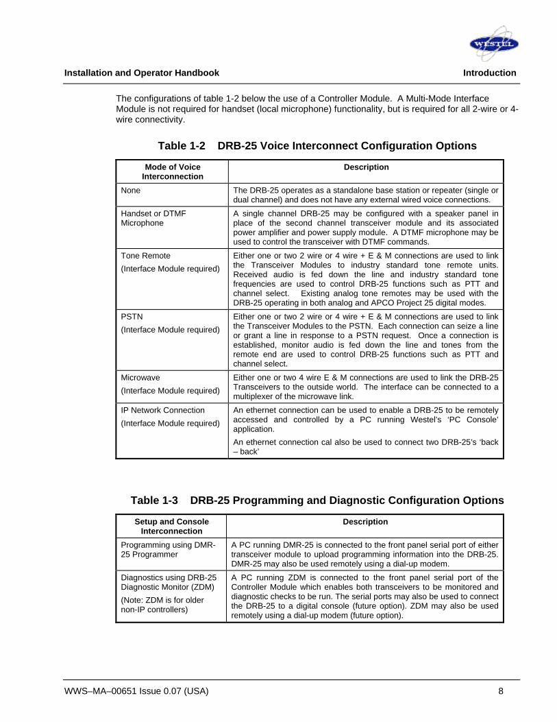
The configurations of table 1-2 below the use of a Controller Module. A Multi-Mode Interface Module is not required for handset (local microphone) functionality, but is required for all 2-wire or 4-wire connectivity.
Table 1-2 DRB-25 Voice Interconnect Configuration Options
Mode of Voice Interconnection
Description
None The DRB-25 operates as a standalone base station or repeater (single or dual channel) and does not have any external wired voice connections.
Handset or DTMF Microphone
A single channel DRB-25 may be configured with a speaker panel in place of the second channel transceiver module and its associated power amplifier and power supply module. A DTMF microphone may be used to control the transceiver with DTMF commands.
Tone Remote (Interface Module required)
Either one or two 2 wire or 4 wire + E & M connections are used to link the Transceiver Modules to industry standard tone remote units. Received audio is fed down the line and industry standard tone frequencies are used to control DRB-25 functions such as PTT and channel select. Existing analog tone remotes may be used with the DRB-25 operating in both analog and APCO Project 25 digital modes.
PSTN (Interface Module required)
Either one or two 2 wire or 4 wire + E & M connections are used to link the Transceiver Modules to the PSTN. Each connection can seize a line or grant a line in response to a PSTN request. Once a connection is established, monitor audio is fed down the line and tones from the remote end are used to control DRB-25 functions such as PTT and channel select.
Microwave (Interface Module required)
Either one or two 4 wire E & M connections are used to link the DRB-25 Transceivers to the outside world. The interface can be connected to a multiplexer of the microwave link.
IP Network Connection (Interface Module required)
An ethernet connection can be used to enable a DRB-25 to be remotely accessed and controlled by a PC running Westel’s ‘PC Console’ application. An ethernet connection cal also be used to connect two DRB-25’s ‘back – back’
Table 1-3 DRB-25 Programming and Diagnostic Configuration Options
Setup and Console Interconnection
Description
Programming using DMR-25 Programmer
A PC running DMR-25 is connected to the front panel serial port of either transceiver module to upload programming information into the DRB-25. DMR-25 may also be used remotely using a dial-up modem.
Diagnostics using DRB-25 Diagnostic Monitor (ZDM) (Note: ZDM is for older non-IP controllers)
A PC running ZDM is connected to the front panel serial port of the Controller Module which enables both transceivers to be monitored and diagnostic checks to be run. The serial ports may also be used to connect the DRB-25 to a digital console (future option). ZDM may also be used remotely using a dial-up modem (future option).

Installation and Operator Handbook Introduction
WWS–MA–00651 Issue 0.07 (USA) 9
Setup and Console Interconnection
Description
Diagnostics using DRB-25 IP Diagnostic Monitor
A PC is connected to an IP enabled Controller Module – this allows both transceivers to be monitored and diagnostic checks to be run. The Ethernet connection can be used to connect the DRB-25 to a digital console (or PC Console). Using a PC Web Browser, the DRB-25 can be controlled or monitored remotely. PC Console offers many features: Critical user info can be viewed, analyze system activity, transmit, receive, and perform remote diagnostics, monitor NAC/TGID activity, change channels, view signal levels, and more.
1.3 SPECIFICATIONS
1.3.1 General Specifications
General Specifications for the DRB-25 are listed in Table 1-4.
Table 1-4 General Specifications Specification Value
Power supply 110 / 240 V AC, 12 V DC
Analog performance ANSI/TIA/EIA603
Digital performance ANSI/TIA102.CAAB
Frequency bands: VHF: 136 to 174 MHz
UHF: 380 to 520 MHz
Operating frequencies Selectable across full band
Dimensions: Width: 19 inches (483 mm)
Height: 14 inches (355 mm or 8 Rack Units)
Depth: 17.5 inches (445 mm)
Weight: Single radio: 26kg (58 lb) Dual radio: 37kg (81 lb)
1.3.2 Power Consumption
Power Consumption for the configurations of the DRB-25 are listed in Table 1-5.
Table 1-5 DC Power Consumption @ 13.8V Configuration First Channel Second Channel
Receive 2.9 A 5.4 A
Transmit 50W 13.2 A 31.8 A
Transmit 100 W 20.4 A 40.4 A

Installation and Operator Handbook Introduction
WWS–MA–00651 Issue 0.07 (USA) 10
1.3.3 Environmental Specifications
The DRB-25 equipment is intended to be located in an indoor environment and meets the environmental specifications detailed in Table 1-6.
Table 1-6 Environmental Specifications Specification Value
Operating Temperature -30°C to +60°C
Storage Temperature -40ºC to +60ºC
Operating Altitude 0 to 5,000 m
Relative humidity (non-condensing)
5% to 95% RH, non-condensing as defined in MIL-STD-810E Method 507.3 (humidity)
EMI/EMC Equivalent to FCC part 15, subpart A, C, and J
1.3.4 Applicable Standards
The DRB-25 is designed to meet the applicable requirements of recommendations and standards detailed in Table 1-7.
Table 1-7 Applicable Standards
Function Standard Digital mode performance ANSI/TIA/EIA 102.CAAB
Analog mode performance TIA/EIA 603
RF Performance NTIA Manual Chapter 5 , FCC - CFR47 part 90, AS4295
PSTN line isolation TS001 (Australia), AS3260 (Australia), FCC part 68 (USA)

Installation and Operator Handbook Equipment Description
WWS–MA–00652 Issue 0.06 (USA) 1
TABLE OF CONTENTS
2 EQUIPMENT DESCRIPTION.............................................................................................................................3
2.1 INTRODUCTION .............................................................................................................................................3 2.2 POWER SOURCE OPTIONS............................................................................................................................3
2.2.1 AC Power Supply................................................................................................................................3 2.2.2 AC Powered with DC Revert ..............................................................................................................3 2.2.3 DC Power Supply................................................................................................................................4 2.2.4 Reference Oscillator Backup Power ...................................................................................................4
2.3 PLUG-IN MODULES.......................................................................................................................................5 2.3.1 Transceiver Module ............................................................................................................................5 2.3.2 Controller Module................................................................................................................................7 2.3.3 Repeater Module ................................................................................................................................9 2.3.4 Power Amplifier Module....................................................................................................................10 2.3.5 Power Supply Module .......................................................................................................................11 2.3.6 4W Interface Module (Discontinued) ................................................................................................13 2.3.7 2-4W Interface Module......................................................................................................................14
LIST OF FIGURES FIGURE 2-1 POWER DISTRIBUTION OF AN AC POWERED DRB-25 ..................................................................................... 3 FIGURE 2-2 POWER DISTRIBUTION OF A DC POWERED DRB-25....................................................................................... 4 FIGURE 2-3 TRANSCEIVER MODULE FRONT PANEL............................................................................................................. 6 FIGURE 2-4 CONTROLLER MODULE FRONT PANEL ............................................................................................................. 8 FIGURE 2-5 POWER AMPLIFIER MODULE FRONT PANEL ................................................................................................... 11 FIGURE 2-6 POWER SUPPLY MODULE FRONT PANEL ...................................................................................................... 12 FIGURE 2-7 4W INTERFACE MODULE FRONT PANEL ........................................................................................................ 13 FIGURE 2-8 2-4W INTERFACE MODULE FRONT PANEL ..................................................................................................... 15
LIST OF TABLES TABLE 2-1 TRANSCEIVER MODULE CONTROLS AND INDICATORS ....................................................................................... 7 TABLE 2-2 CONTROLLER MODULE CONTROLS AND INDICATORS ........................................................................................ 9 TABLE 2-3 POWER SUPPLY MODULE CONTROLS AND INDICATORS .................................................................................. 13 TABLE 2-4 4W INTERFACE MODULE EXTERNAL INTERFACES ........................................................................................... 14

Installation and Operator Handbook Equipment Description
WWS–MA–00652 Issue 0.06 (USA) 2
This page left blank intentionally.

Installation and Operator Handbook Equipment Description
WWS–MA–00652 Issue 0.06 (USA) 3
2 EQUIPMENT DESCRIPTION
2.1 INTRODUCTION
DRB-25 equipment consists of modular hardware, which is easily installed as a desktop cabinet, floor-mount cabinet or into standard 19-inch racks.
The DRB-25 chassis and its component modules are described in the following paragraphs.
2.2 POWER SOURCE OPTIONS
2.2.1 AC Power Supply
The DRB-25 may be powered from the 240 or 110 V AC power supply via one or two Power Supply Modules. Figure 2-1 shows the power distribution of an AC powered DRB-25.
7 V
12 V
Option for Second Channel
12V DC Standby Power
110/240 V AC Supply
Switch
Power Supply Module 1
System PSU
Fans
Power SupplyModule 2
Power Amplifier 2
Power Amplifier 1
Transceiver Module 1
Transceiver Module 2
Controller/Repeater & Interface Modules
Figure 2-1 Power Distribution of an AC powered DRB-25
2.2.2 AC Powered with DC Revert
The DRB-25 may be powered from the 240 or 110 V AC power supply via one or two Power Supply Modules with provision for 12V DC Revert (13.8V DC nominal +/- 20%) in the event that the AC power fails.
When using DC Revert the RF output power of the DRB-25 is derated by up to 3dB if the DC voltage is at the low end of the specified range. Operation below 11V DC is not recommended. When operating from a direct DC power source the Power Supply Modules are replaced with blank panels.

Installation and Operator Handbook Equipment Description
WWS–MA–00652 Issue 0.06 (USA) 4
AC powered with 24 and 48 V DC revert is also available using external power supplies, however, where a 48 V DC battery backed supply of sufficient capacity is available it is generally preferable to use this as the main power source for the DRB-25.
2.2.3 DC Power Supply
The DRB-25 may be powered directly from a 12 V DC (13.8V DC nominal +/- 20%) power source using the AC/DC Revert option. In scenarios where the DC supply is likely to drop below 11V DC it is recommended that a DC-DC supply is used.
Figure 2-2 shows the power distribution of a DC powered DRB-25.
7 V
12 V
Option for Second Channel
12V DC Standby Power
12 V DC Supply Switch
Optional DC/DCConverter
System PSU
Fans
Optional DC/DCConverter
Power Amplifier 2
Power Amplifier 1
Transceiver Module 1
Transceiver Module 2
Controller/Repeater & Interface Modules
Figure 2-2 Power Distribution of a DC Powered DRB-25
2.2.4 Reference Oscillator Backup Power
For Controller / Repeater modules fitted with a 0.1ppm OCXO the DRB-25 has provision for a user to connect a 12V DC backup supply to keep the system reference oscillator oven at its operating temperature in the event of a brief primary power failure. An interface module connector acts as the connection point for the keep-alive power.
If the backup supply is not used, any interruption to the primary supply will cause the reference oscillator to lose stability, and a warm-up time of up to ten minutes may be required after power is restored to the DRB-25.

Installation and Operator Handbook Equipment Description
WWS–MA–00652 Issue 0.06 (USA) 5
2.3 PLUG-IN MODULES
The DRB-25 has the following types of plug-in Modules:
• Transceiver Module.
• Controller Module
• Repeater Module
• Power Amplifier Module.
• Interface Module.
• Power Supply Module.
2.3.1 Transceiver Module
The Transceiver Module (TM) provides full duplex radio operation for analog and digital modulation schemes. Each module consists of an RF card for receive and transmit and a daughter board for digital signal processing. Modules are standard half-Eurocard layout measuring 10.5 inches (6 Rack Units) high by 10 inches (250 mm) deep. The Transceiver Modules plug into a common backplane with the Controller Module, providing seamless transfer and switching of traffic and control data.
Transceiver Modules are specific to frequency bands and are available for frequency bands; VHF (136 to 174 MHz), and UHF (380 to 520 MHz). Each Transceiver module may be programmed with up to 512 channels.
Transceiver Modules of different bands are interchangeable provided the associated Power Amplifier is also changed. The Transceiver Module is powered by 12 V and 7 V supplies from the System Power Supply within the case of the DRB-25.
Two RJ style connectors are provided on the module front panel. The upper connector (RJ11) provides a standard RS-232 serial interface that allows maintenance staff to program and configure the module using the Transceiver Module Programmer application software from an external PC. The lower (RJ45) connector provides an audio interface for the connection of a speaker, microphone or handset.
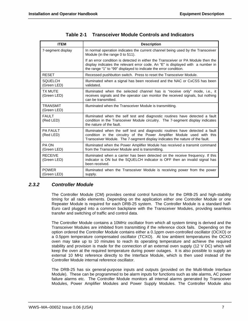
Internally to the DRB-25 the Transceiver Module provides two connections to its associated power amplifier; an RF output and a serial data link for control and communication between the two modules. Figure 2-3 shows the front panel controls, indicators and connectors and Table 2-1 lists the control and indicator functions.

Installation and Operator Handbook Equipment Description
WWS–MA–00652 Issue 0.06 (USA) 6
Figure 2-3 Transceiver Module Front Panel
The Transceiver Module provides internal interfaces for audio, data and control. The Transceiver Module also provides an audio output interface for connection to a front panel speaker when configured as a single channel system with optional front panel speaker module.
Installation and Operator Handbook Equipment Description
WWS–MA–00652 Issue 0.06 (USA) 7
Table 2-1 Transceiver Module Controls and Indicators
ITEM Description 7-segment display In normal operation indicates the current channel being used by the Transceiver
Module (in the range 0 to 511). If an error condition is detected in either the Transceiver or PA Module then the display indicates the relevant error code. An “E” is displayed with a number in the range “1” to “99” displayed to indicate the error condition.
RESET Recessed pushbutton switch. Press to reset the Transceiver Module.
SQUELCH (Green LED)
Illuminated when a signal has been received and the NAC or CxCSS has been validated.
TX MUTE (Green LED)
Illuminated when the selected channel has is “receive only” mode, i.e., it receives signals and the operator can monitor the received signals, but nothing can be transmitted.
TRANSMIT (Green LED)
Illuminated when the Transceiver Module is transmitting.
FAULT (Red LED)
Illuminated when the self test and diagnostic routines have detected a fault condition in the Transceiver Module circuitry. The 7-segment display indicates the nature of the fault.
PA FAULT (Red LED)
Illuminated when the self test and diagnostic routines have detected a fault condition in the circuitry of the Power Amplifier Module used with this Transceiver Module. The 7-segment display indicates the nature of the fault.
PA ON (Green LED)
Illuminated when the Power Amplifier Module has received a transmit command from the Transceiver Module and is transmitting.
RECEIVE (Green LED)
Illuminated when a carrier has been detected on the receive frequency. If this indicator is ON but the SQUELCH indicator is OFF then an invalid signal has been received.
POWER (Green LED)
Illuminated when the Transceiver Module is receiving power from the power supply.
2.3.2 Controller Module
The Controller Module (CM) provides central control functions for the DRB-25 and high-stability timing for all radio elements. Depending on the application either one Controller Module or one Repeater Module is required for each DRB-25 system. The Controller Module is a standard half-Euro card plugged into a common backplane with the Transceiver Modules, providing seamless transfer and switching of traffic and control data.
The Controller Module contains a 10MHz oscillator from which all system timing is derived and the Transceiver Modules are inhibited from transmitting if the reference clock fails. Depending on the option ordered the Controller Module contains either a 0.1ppm oven-controlled oscillator (OCXO) or a 0.5ppm temperature compensated oscillator (TCXO). At low ambient temperatures the OCXO oven may take up to 10 minutes to reach its operating temperature and achieve the required stability and provision is made for the connection of an external oven supply (12 V DC) which will keep the oven at the required temperature during power outages. It is also possible to supply an external 10 MHz reference directly to the Interface Module, which is then used instead of the Controller Module internal reference oscillator.
The DRB-25 has six general-purpose inputs and outputs (provided on the Multi-Mode Interface Module). These can be programmed to be alarm inputs for functions such as site alarms, AC power failure alarms etc. The Controller Module monitors all internal alarms generated by Transceiver Modules, Power Amplifier Modules and Power Supply Modules. The Controller Module also
Installation and Operator Handbook Equipment Description
WWS–MA–00652 Issue 0.06 (USA) 8
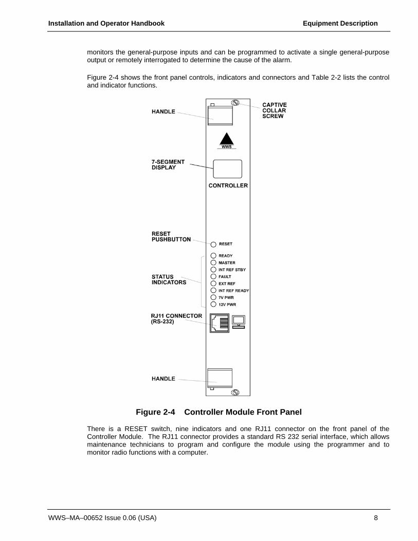
monitors the general-purpose inputs and can be programmed to activate a single general-purpose output or remotely interrogated to determine the cause of the alarm.
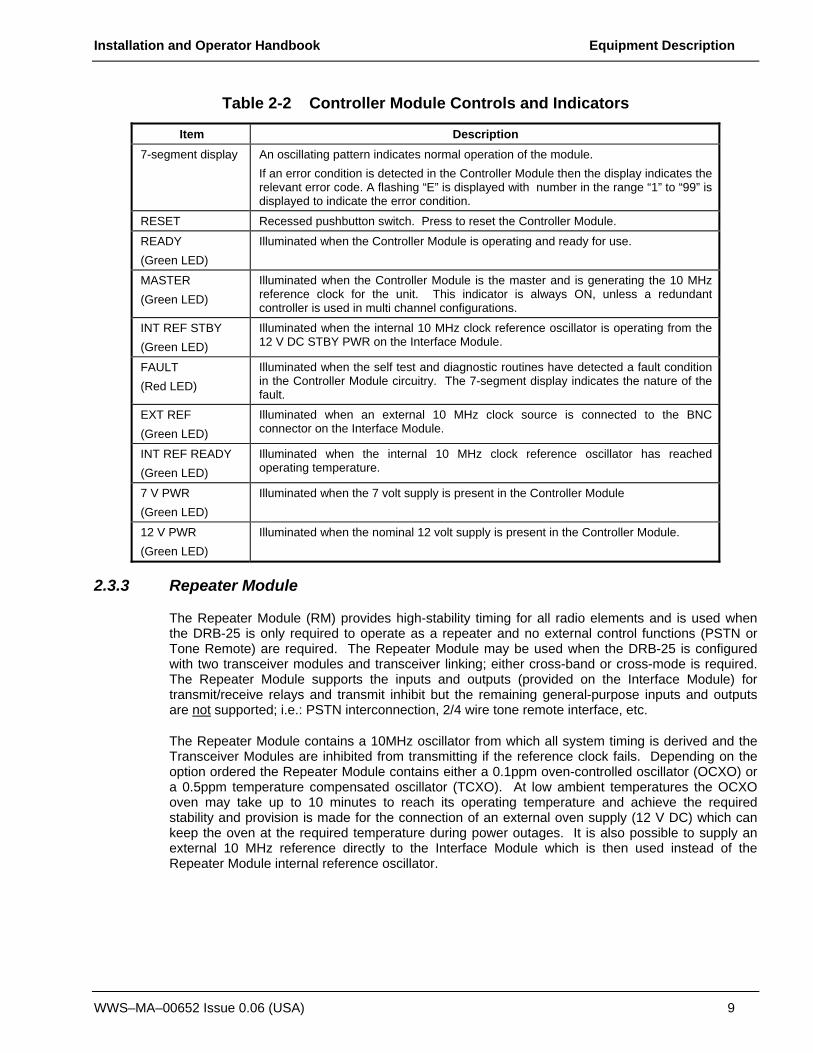
Figure 2-4 shows the front panel controls, indicators and connectors and Table 2-2 lists the control and indicator functions.
Figure 2-4 Controller Module Front Panel
There is a RESET switch, nine indicators and one RJ11 connector on the front panel of the Controller Module. The RJ11 connector provides a standard RS 232 serial interface, which allows maintenance technicians to program and configure the module using the programmer and to monitor radio functions with a computer.
Installation and Operator Handbook Equipment Description
WWS–MA–00652 Issue 0.06 (USA) 9
Table 2-2 Controller Module Controls and Indicators
Item Description 7-segment display An oscillating pattern indicates normal operation of the module.
If an error condition is detected in the Controller Module then the display indicates the relevant error code. A flashing “E” is displayed with number in the range “1” to “99” is displayed to indicate the error condition.
RESET Recessed pushbutton switch. Press to reset the Controller Module.
READY (Green LED)
Illuminated when the Controller Module is operating and ready for use.
MASTER (Green LED)
Illuminated when the Controller Module is the master and is generating the 10 MHz reference clock for the unit. This indicator is always ON, unless a redundant controller is used in multi channel configurations.
INT REF STBY (Green LED)
Illuminated when the internal 10 MHz clock reference oscillator is operating from the 12 V DC STBY PWR on the Interface Module.
FAULT (Red LED)
Illuminated when the self test and diagnostic routines have detected a fault condition in the Controller Module circuitry. The 7-segment display indicates the nature of the fault.
EXT REF (Green LED)
Illuminated when an external 10 MHz clock source is connected to the BNC connector on the Interface Module.
INT REF READY (Green LED)
Illuminated when the internal 10 MHz clock reference oscillator has reached operating temperature.
7 V PWR (Green LED)
Illuminated when the 7 volt supply is present in the Controller Module
12 V PWR (Green LED)
Illuminated when the nominal 12 volt supply is present in the Controller Module.
2.3.3 Repeater Module
The Repeater Module (RM) provides high-stability timing for all radio elements and is used when the DRB-25 is only required to operate as a repeater and no external control functions (PSTN or Tone Remote) are required. The Repeater Module may be used when the DRB-25 is configured with two transceiver modules and transceiver linking; either cross-band or cross-mode is required. The Repeater Module supports the inputs and outputs (provided on the Interface Module) for transmit/receive relays and transmit inhibit but the remaining general-purpose inputs and outputs are not supported; i.e.: PSTN interconnection, 2/4 wire tone remote interface, etc.
The Repeater Module contains a 10MHz oscillator from which all system timing is derived and the Transceiver Modules are inhibited from transmitting if the reference clock fails. Depending on the option ordered the Repeater Module contains either a 0.1ppm oven-controlled oscillator (OCXO) or a 0.5ppm temperature compensated oscillator (TCXO). At low ambient temperatures the OCXO oven may take up to 10 minutes to reach its operating temperature and achieve the required stability and provision is made for the connection of an external oven supply (12 V DC) which can keep the oven at the required temperature during power outages. It is also possible to supply an external 10 MHz reference directly to the Interface Module which is then used instead of the Repeater Module internal reference oscillator.
Installation and Operator Handbook Equipment Description
WWS–MA–00652 Issue 0.06 (USA) 10
2.3.4 Power Amplifier Module
The Power Amplifier Module (PAM) is a 6RU high plug-in module. One Power Amplifier Module is required for each Transceiver Module. Power Amplifier Modules are specific to frequency bands:
50W VHF: 136 – 165 MHz and 145 – 174 MHz (special order)
100W VHF: 136 – 165 MHz and 145 – 174 MHz
50W UHF: 380 – 420 MHz, 400 – 470 MHz, and 450 – 520 MHz
100W UHF: 380 – 420 MHz, 400 – 470 MHz, and 450 – 520 MHz (special order)
Each Power Amplifier Module has an on-board microcontroller, which supervises its operation and reports alarms via a control link to the associated radios. Power output is adjustable over a 10 dB range in increments of less than 1 dB.
Each Power Amplifier Module is powered by its associated Power Supply Module.
Figure 2-5 shows the front panel layout. he Power Amplifier Module has two connectors. The N-type connector is the Power Amplifier output connector, and the D connector contains RF input, DC power, and serial communications lines.

Installation and Operator Handbook Equipment Description
WWS–MA–00652 Issue 0.06 (USA) 11
Figure 2-5 Power Amplifier Module Front Panel
2.3.5 Power Supply Module
The Power Supply Module provides the system power supply and one Power Amplifier Module with DC power derived from the 240 or 110 V AC power. Different versions are available depending on the Power Amplifier Module being used:
• 240/110 V AC to 12 V DC for 50 W Power Amplifier Modules.
• 110 V AC to 12 V DC for VHF 100W and UHF 50 W Power Amplifier Modules.
• 240 V AC to 12 V DC for VHF 100W and UHF 50 W Power Amplifier Modules.
The inputs of all power supplies are fuse-protected and the outputs are over-current protected. They have dry contact (relay contacts) alarm outputs that close when the unit is operating correctly and

Installation and Operator Handbook Equipment Description
WWS–MA–00652 Issue 0.06 (USA) 12
open in the event of a malfunction. Figure 2-6 shows the Power Supply Module front panel indicators and Table 2-3 lists the indicator functions.
Figure 2-6 Power Supply Module Front Panel

Installation and Operator Handbook Equipment Description
WWS–MA–00652 Issue 0.06 (USA) 13
Table 2-3 Power Supply Module Controls and Indicators
Item Description ON/OFF Switch Controls application of AC supply to the Power Supply Module.
Red neon indicator (part of switch)
Illuminated when supply is present.
12 V (Green LED)
Illuminated when the DC supply is present.
FAULT (Red LED) Illuminated when there is a fault within the Power Supply Module
2.3.6 4W Interface Module (Discontinued)
The 4W Interface Module (IM) has been replaced by the 2-4W Interface Module. The following is provided for existing 4W Interface Module users.
The 4W Interface Module provides connections for the DRB-25 external interfaces. The Front Panel of the Interface Module is shown in Figure 2-7 and the connector functions listed in Table 2-4. Connector pin-outs are listed in section 3.6.5.
Figure 2-7 4W Interface Module Front Panel
The 4-wire configuration of the Line 1 and Line 2 interfaces for telephone/microwave/tone remote control connection is provided by a line interface daughterboard on the Interface Module.

Installation and Operator Handbook Equipment Description
WWS–MA–00652 Issue 0.06 (USA) 14
Table 2-4 4W Interface Module External Interfaces
Designation Connector Function LINE 1 RJ45 Radio 1 connections for:
4 wire + E & M microwave interconnect 4 wire tone remote unit
LINE 2 RJ45 Radio 2 connections for: 4 wire + E & M microwave interconnect 4 wire tone remote unit
SERIAL 1 DB9 Socket Radio 1 diagnostic data connection (RS-232)
SERIAL 2 DB9 Socket Radio 2 diagnostic data connection (RS-232)
LINK DB9 Plug RS485 serial data connection for APCO Project 25 Fixed Station Interface (Ef) , digital console interface or multi-site voting (future options)
NET RJ45 Ethernet connection for VOIP and network management interface (future option)
I/O DB25 Socket General purpose input and output lines (6 inputs and 6 outputs), including dedicated outputs for antenna relay control and dedicated inputs for transmit disable
REF IN BNC External 10 MHz reference oscillator input
STBY PWR 2-pin plug Standby power for reference oscillator oven.
-48 V IN 2-pin plug DC input for E & M signaling
The general-purpose digital I/O provides six configurable inputs and outputs. Two of the output lines may be configured by jumper selection in the Interface Card to provide to drive 12 volt antenna relays for each of the transceivers. All other outputs, and these two when not configured as antenna drivers, provide optically-isolated contact closures which can be used to control other equipment.
The six inputs are also optically isolated. With an input of 5v to 10v they are sensed as active (on), when open circuited, they are sensed as inactive (off). The first two inputs are used to disable the transmitter during test.
The general purpose input and output lines, apart from the antenna relay outputs and transmit disable inputs, are unused in the present software release. In future releases user-configurability will be available.
2.3.7 2-4W Interface Module
The 2-4W Interface Module (IM) provides connections for the DRB-25 external interfaces. The Front Panel of the Interface Module is shown in Figure 2-7 and the connector functions listed in Table 2-4. Connector pin-outs are listed in section 3.6.5

Installation and Operator Handbook Equipment Description
WWS–MA–00652 Issue 0.06 (USA) 15
Figure 2-8 2-4W Interface Module Front Panel
The 2-4-wire configuration of the Line 1 and Line 2 interfaces for telephone/microwave/tone remote control connection are provided by a daughterboard on the Interface Module.
Designation Connector Function LINE 1 RJ45 Radio 1 connections for:
2 or 4 wire PSTN or PABX 2 or 4 wire + E & M microwave interconnect 2 or 4 wire tone remote unit
LINE 2 RJ45 Radio 2 connections for: 2 or 4 wire PSTN or PABX 2 or 4 wire + E & M microwave interconnect 2 or 4 wire tone remote unit
LINK DB9 Plug RS485 serial data connection for APCO Project 25 Fixed Station Interface (Ef) , digital console interface or multi-site voting (future options)
NET RJ45 Ethernet connection for VOIP and network management interface (future option)
I/O DB25 Socket Radio 1 and 2 diagnostic data Standby power for reference oscillator oven. General purpose input and output lines (6 inputs and 6 outputs), including dedicated outputs for antenna relay control and dedicated inputs for transmit disable
STBY PWR 2-pin plug Standby power for reference oscillator oven.
-48 V IN 2-pin plug DC input for E & M signaling

Installation and Operator Handbook Equipment Description
WWS–MA–00652 Issue 0.06 (USA) 16
This page left blank intentionally.

Installation and Operator Handbook Installation Instructions
WWS–MA–00653 Issue 0.09 (USA) 1
TABLE OF CONTENTS
3 INSTALLATION INSTRUCTIONS ..........................................................................................................3
3.1 General............................................................................................................................................................ 3
3.2 Safety Precautions ....................................................................................................................................... 3
3.3 Site Requirements........................................................................................................................................ 4 3.3.1 Antenna Installation and Safe Operating Distances.......................................................................... 4 3.3.2 Desk/Floor Space or Rack Mounting Considerations ....................................................................... 4 3.3.3 Lightning Protection................................................................................................................................ 5
3.4 Delivery and Unpacking.............................................................................................................................. 5
3.5 Installation...................................................................................................................................................... 6 3.5.1 Tools Required........................................................................................................................................ 6 3.5.2 Installing the DRB-25 Cabinet .............................................................................................................. 7 3.5.3 Configuring DRB-25 Identity (Box ID).................................................................................................. 7 3.5.4 Installing the Modules ............................................................................................................................ 9
3.5.4.1 Power Supply Module ...................................................................................................................... 11 3.4.4.2 Power Amplifier Module................................................................................................................... 11 3.5.4.3 Transceiver Module.......................................................................................................................... 12 3.5.4.4 Controller Module (and Repeater Module) ................................................................................... 12 3.5.4.5 Interface Module ............................................................................................................................... 12 3.5.4.6 Speaker Panel and Microphone ..................................................................................................... 12
3.5.5 Configuring the IP-Enabled Controller............................................................................................... 13 3.5.5.1 Network Parameters......................................................................................................................... 13
3.5.5.1.1 IP Address Configuration via DHCP...................................................................................... 13 3.5.5.1.2 IP Address Configuration via Serial Port .............................................................................. 14
3.5.6 Other Configuration Settings............................................................................................................... 15 3.5.6.1 DNS Servers...................................................................................................................................... 17 3.5.6.2 NTP Server ........................................................................................................................................ 17 3.5.6.3 Timezone ........................................................................................................................................... 17 3.5.6.4 Input/Output Daemon....................................................................................................................... 17 3.5.6.5 Telnet Daemon.................................................................................................................................. 18 3.5.6.6 Web Login.......................................................................................................................................... 18 3.5.6.7 IP Console Login .............................................................................................................................. 18
3.5.7 Web Interface ........................................................................................................................................ 18 3.5.7.1 Home page ........................................................................................................................................ 18 3.5.7.2 Transceiver Status Page ................................................................................................................. 20 3.5.7.3 Test Signal Generation Page.......................................................................................................... 21 3.5.7.4 Feature Licensing Page................................................................................................................... 22 3.5.7.5 Login Page......................................................................................................................................... 22
3.5.8 Configuring Users and Passwords on the Controller ...................................................................... 23
3.6 Connections................................................................................................................................................. 23 3.6.1 Grounding Strap.................................................................................................................................... 23 3.6.2 AC Power............................................................................................................................................... 23 3.6.3 DC Power............................................................................................................................................... 23 3.6.4 Antenna Cabling ................................................................................................................................... 24 3.6.5 External Interfaces................................................................................................................................ 24

Installation and Operator Handbook Installation Instructions
WWS–MA–00653 Issue 0.09 (USA) 2
3.6.5.1 Transceiver Module.......................................................................................................................... 24 3.6.5.1.1 Transceiver Module Audio Connector ................................................................................... 24 3.6.5.1.2 Transceiver Module Programming Connector ..................................................................... 25
3.6.5.3 Controller Module ............................................................................................................................. 25 3.6.5.3.1 Controller Module Serial Data Connector ............................................................................. 25
3.6.5.4 2/4W Interface Module..................................................................................................................... 26 3.6.5.4.1 Radio Serial Data ..................................................................................................................... 26 3.6.5.4.2 Analog Line Connection .......................................................................................................... 26 3.6.5.4.3 Analog Line Jumper Settings.................................................................................................. 27 3.6.5.4.4 RS-485 serial data.................................................................................................................... 29 3.6.5.4.5 Ethernet ..................................................................................................................................... 29 3.6.5.4.6 General Purpose Input/Output Lines ..................................................................................... 29 3.6.5.4.7 External 10 MHz reference source ........................................................................................ 30 3.6.5.4.8 Standby power .......................................................................................................................... 31 3.6.5.4.9 -48 V DC input .......................................................................................................................... 31
3.6.5.5 4W Interface Module........................................................................................................................... 31
LIST OF FIGURES Figure 3-1 DRB-25 Rack Mounting Arrangement (Optional) ................................................................ 7 Figure 3-2 DRB-25 Front Module Positions ............................................................................................. 9 Figure 3-3 DRB-25 with Speaker Panel and Microphone fitted .......................................................... 10 Figure 3-4 DRB-25 Rear Module Positions (4W Interface Module) ................................................... 11

Installation and Operator Handbook Installation Instructions
WWS–MA–00653 Issue 0.09 (USA) 3
3 INSTALLATION INSTRUCTIONS
3.1 GENERAL
This chapter provides a detailed description of the installation procedure for the DRB-25 Dual Channel Radio System and should be read before starting the installation. Use the Installation Instructions in conjunction with the configuration checklist for the specific system being installed.
3.2 SAFETY PRECAUTIONS
Observe standard safety procedures for the handling of electronic equipment:
WARNING
FOLLOW CORRECT LIFTING PROCEDURES FOR HEAVY ELECTRONIC EQUIPMENT.
ATTE NTIONOBSERVE
PRECAUTIONSF OR HANDLINGELECTROSTATIC
SENSITIVEDEVICES
When removing or handling cards, use an anti-static wrist strap connected to ground and always place the card on an anti-static mat
Handle modules by their edges and do not touch components or connectors.
Avoid placing the DRB-25 near any source of excessive heat
Avoid placing the DRB-25 near a naked flame
Avoid placing the DRB-25 in a wet or damp location
Do not subject the DRB-25 to severe mechanical shock

Installation and Operator Handbook Installation Instructions
WWS–MA–00653 Issue 0.09 (USA) 4
3.3 SITE REQUIREMENTS
3.3.1 Antenna Installation and Safe Operating Distances
Before installing the DRB-25 at the operating site, the following details regarding desk or floor space, rack clearance and lightning protection should be considered.
Use only manufacturer or dealer supplied antenna.
Antenna Minimum Safe Distance: 70 cm, 50% Duty Cycle.
Antenna Gain: zero dBd referenced to a dipole.
The Federal Communications Commission has adopted a safety standard for human exposure to RF (Radio Frequency) energy which is below the OSHA Occupational Safety and Health Act) limits.
Antenna Mounting: The antenna supplied by the manufacturer or radio dealer must not be mounted at a location such that during radio transmission, any person or persons can come closer than the above indicated minimum safe distance to the antenna i.e. 70 cm.
To comply with current FCC RF Exposure limits, the antenna must be installed at or exceeding the minimum safe distance shown above, and in accordance with the requirements of the antenna manufacturer or supplier.
Base Station Installation: The antenna should be fixed-mounted on an outdoor permanent structure. RF Exposure compliance must be addressed at the time of installation.
Antenna Substitution: Do not substitute any antenna for the one supplied or recommended by the manufacturer or radio dealer. You may be exposing person or persons to excess radio frequency radiation. You may contact your radio dealer or the manufacturer for further instructions.
Warning: Maintain a separation distance from the antenna to a person(s) of at least 70 cm. You, as the qualified end-user of this radio device must control the exposure conditions of bystanders to ensure the minimum separation distance (above) is maintained between the antenna and nearby persons for satisfying RF Exposure compliance. The operation of this transmitter must satisfy the requirements of 0ccupational /Controlled Exposure Environment, for work-related use. Transmit only when person(s) are at least the minimum distance from the properly installed, externally mounted antenna.
3.3.2 Desk/Floor Space or Rack Mounting Considerations
The DRB-25 is 19 inches (483 mm) wide (standard 19 inch rack mountable), 14 inches (355 mm) high, 17.4 inches (440 mm) deep, and weighs 61 lb (28 kg) for a single radio configuration, or 85 lb (39 kg) for a dual radio configuration.
When mounting the DRB-25 Cabinet:
• Ensure that the DRB-25 is securely mounted.
• Ensure that the DRB-25 air vents are clear of obstructions.

Installation and Operator Handbook Installation Instructions
WWS–MA–00653 Issue 0.09 (USA) 5
• Provide sufficient space on all sides to of the DRB-25 to allow adequate access to the equipment and cables.
• Ensure that there is adequate space for entry of external cables (antenna and AC power cables) at the rear of the unit without the need for small radius bends.
3.3.3 Lightning Protection
To minimize damage to equipment, or injury to maintainers, a complete system of lightning protection and grounding connections should be installed. The following points should be considered:
• All down conductors, bonding interconnections, ground rings and radial tapes should be un-insulated solid copper tape at least 25 x 3 mm in cross section. All connection clamps and supports should be protected by non-reactive paste or tape.
• The use of gas lightning arresters or metal oxide varistors is recommended on line interfaces, including antenna cables.
• Protected test points should be included where appropriate and sacrificial grounding lugs should be clearly marked and accessible for periodic inspection and replacement if necessary.
• Use a large copper strap to take outer cable casings to a central ground bonding point.
• Antenna support structures, whether on the ground or on a building, should be connected to an o ring arrangement (or equivalent) via sacrificial ground lugs.
• A ground ring consists of copper tape with driver ground electrodes or radial tapes around the base of the structure (as close to it as possible), buried approximately 24 inches (0.6 m), where soil conditions allow.
• The main building and any other metalwork structures within 3m should be connected to a ground ring.
3.4 DELIVERY AND UNPACKING
The DRB-25 cabinet and supporting modules are packed and transported in customized packages that conform to best commercial practices for transportation and protection of electronic assemblies.
The DRB-25 cabinet is delivered complete, requiring only the fitting of the plug in modules.
In addition to the DRB-25 cabinet, the following Modules will be supplied in separate packages. The type and number of modules will depend on the configuration of the DRB-25
• One or two Power Supply Modules.
• One or two Power Amplifier Modules.
• One or two Transceiver Modules.
• Controller or Repeater Module.
• Interface Module.

Installation and Operator Handbook Installation Instructions
WWS–MA–00653 Issue 0.09 (USA) 6
If ordered, a programming kit will be provided, including a programming disk and interface cable.
Before unpacking, examine the packages for evidence of external damage, water ingress or vermin activity, which may have occurred during transportation.
Examine the delivery docket or shipping check list to confirm that the correct items for the intended DRB-25 configuration has been delivered.
Notify the supplier or its agent immediately if any discrepancy is noted.
Unpack the DRB-25 as follows:
• Carefully remove the DRB-25 cabinet from its packaging and relocate to a convenient level work surface.
• Remove all protective wrapping and inspect the cabinet for signs of damage or loose parts. Notify the supplier or its agent immediately if any is noted.
• Remove each of the modules in turn from their packages, unwrap and inspect as for the cabinet. Notify the supplier or its agent immediately if any damage or loose parts are noted.
3.5 INSTALLATION
Take care to align each module correctly into its guide rails. Ensure that the module is correctly mated into the backplane of the DRB-25 and the connectors are firmly seated. Failure to do so may result in damage to the module or DRB-25 system.
3.5.1 Tools Required
The following tools should be on hand during installation:
• Flat-bladed screwdrivers (small, medium and large).
• Cross-recessed (Phillips) screwdriver (large and medium).
• Cable ties and cutters.
• 9/32 inch (7 mm) hexagonal nut driver.
• Multimeter with pointed probes for continuity and DC voltage measurements.

Installation and Operator Handbook Installation Instructions
WWS–MA–00653 Issue 0.09 (USA) 7
3.5.2 Installing the DRB-25 Cabinet
If the DRB-25 is to be desk mounted then screw the supplied feet to the four threaded inserts on the underside of the case and position the case as required.
If the cabinet is to be rack mounted using 19” rack mount brackets (an optional accessory), then assemble the rack mounting brackets and case as shown in Figure 3-1: DRB-25 Rack Mounting Arrangement:
1. Fit the brackets to the rack using the caged nuts and bolt supplied.
2. Slide the DRB-25 case into the brackets.
3. Fix the DRB-25 in place by locating the two studs at the rear of the case through the hole in each bracket, and secure using the nuts supplied.
4. Set the DRB-25’s Identity (Box ID) and fit the modules as described in the following sections.
Figure 3-1 DRB-25 Rack Mounting Arrangement (Optional)
3.5.3 Configuring DRB-25 Identity (Box ID)
An 8-way DIP switch on the backplane adjacent to the right transceiver connections enables a Box ID to be set for each DRB-25. The switch is accessed from the front of the unit with the modules removed. A total of 256 identities are available.
The Box ID is used by each Transceiver to determine its default settings on power-up. Transceiver modules can be programmed with up to 512 operating channels, and the default

Installation and Operator Handbook Installation Instructions
WWS–MA–00653 Issue 0.09 (USA) 8
operating channel for each Transceiver is determined by the DRB-25 Box ID as detailed in Appendix A Table A-1.
DRB-25 Box ID settings may be defined in a plan that covers all DRB-25 units in the network. The Box ID is also used by the Controller Module for network management purposes to enable it to identify itself within a network.
The default factory setting is a box identity of zero.
To set the DIP switches:
1. Locate the DIP switch on the upper right of the backplane, through the front of the DRB-25 case (without the plug in modules installed).
2. Using a small flat-bladed screwdriver or pen, set the eight sections of the DIP switch to the desired Box ID, according to and the intended DRB-25 Box numbering plan.
The Switch 1 (LSB) is the top switch; Switch 8 (MSB) is the lower switch. OFF is to the left, ON is to the right.

Installation and Operator Handbook Installation Instructions
WWS–MA–00653 Issue 0.09 (USA) 9
3.5.4 Installing the Modules
Refer to the following figures (Figure 3-2, Figure 3-3 and Figure 3-4) to identify the correct position for each module within the DRB-25 cabinet. Install the supplied modules as detailed in the following paragraphs.
Figure 3-2 DRB-25 Front Module Positions

Installation and Operator Handbook Installation Instructions
WWS–MA–00653 Issue 0.09 (USA) 10
Figure 3-3 DRB-25 with Speaker Panel and Microphone fitted

Installation and Operator Handbook Installation Instructions
WWS–MA–00653 Issue 0.09 (USA) 11
Figure 3-4 DRB-25 Rear Module Positions (4W Interface Module)
3.5.4.1 Power Supply Module
To install the Power Supply Module:
1. Carefully insert the Power Supply Module into its position from the front of the cabinet by aligning the guide rails and pushing home until the backplane connector is correctly mated and the panel is flush with the adjacent panels.
2. Using a medium sized flat-bladed screwdriver, secure the Module with the four captive collar screws. Do not over-tighten.
3. If two Power Supply Modules are supplied, repeat for the other module.
3.4.4.2 Power Amplifier Module
To install the Power Amplifier Module:
1. Locate the coax lead with a right-angled N-type connector. Stretch the lead out of the box and partially insert the Power Amplifier into its card slot. Attach the N-type connector to the mating connector on the Power Amplifier, then carefully insert the Power Amplifier Module fully into position from the front of the cabinet. Push the module home so that the backplane connector is correctly mated and the panel is flush with the adjacent panels.
Installation and Operator Handbook Installation Instructions
WWS–MA–00653 Issue 0.09 (USA) 12
2. Using a medium sized flat-bladed screwdriver, secure the Module using the four captive collar screws. Do not over-tighten.
3. If two Power Amplifier Modules are supplied, repeat for the other module.
3.5.4.3 Transceiver Module
To install the Transceiver Module:
1. Carefully insert the Transceiver Module into its position from the front of the cabinet by aligning the guide rails and pushing home until the backplane connector is correctly mated and the panel is flush with the adjacent panels.
2. Using a medium sized flat-bladed screwdriver, secure the Module using the two captive collar screws. Do not over-tighten.
3. If two Transceiver Modules are supplied repeat for the other module.
3.5.4.4 Controller Module (and Repeater Module)
To install the Controller / Repeater Module:
1. Carefully insert the Controller Module into its position from the front of the cabinet by aligning the guide rails and pushing home until the backplane connector is correctly mated and the panel is flush with the adjacent panels.
2. Using a medium sized flat-bladed screwdriver, secure the Module using the two captive collar screws. Do not over-tighten.
3.5.4.5 Interface Module
To install the Interface Module:
1. Carefully insert the Interface Module into its position from the rear of the cabinet by aligning the guide rails and pushing home until the backplane connector is correctly mated and the panel is flush with the adjacent panels.
2. Using a medium sized Phillips screwdriver, secure the Module using the two captive screws. Do not over-tighten.
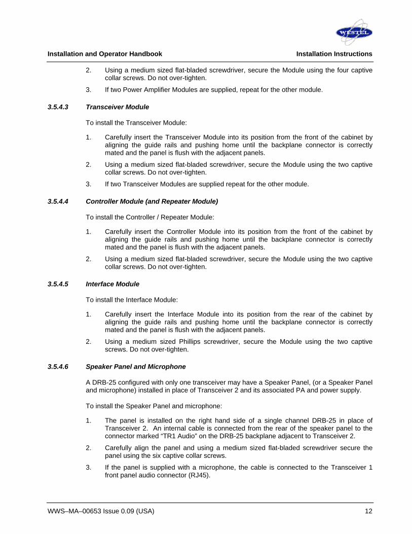
3.5.4.6 Speaker Panel and Microphone
A DRB-25 configured with only one transceiver may have a Speaker Panel, (or a Speaker Panel and microphone) installed in place of Transceiver 2 and its associated PA and power supply.
To install the Speaker Panel and microphone:
1. The panel is installed on the right hand side of a single channel DRB-25 in place of Transceiver 2. An internal cable is connected from the rear of the speaker panel to the connector marked “TR1 Audio” on the DRB-25 backplane adjacent to Transceiver 2.
2. Carefully align the panel and using a medium sized flat-bladed screwdriver secure the panel using the six captive collar screws.
3. If the panel is supplied with a microphone, the cable is connected to the Transceiver 1 front panel audio connector (RJ45).
Installation and Operator Handbook Installation Instructions
WWS–MA–00653 Issue 0.09 (USA) 13
3.5.5 Configuring the IP-Enabled Controller This section is only applicable to IP-Enabled (Ethernet) Controller Modules.
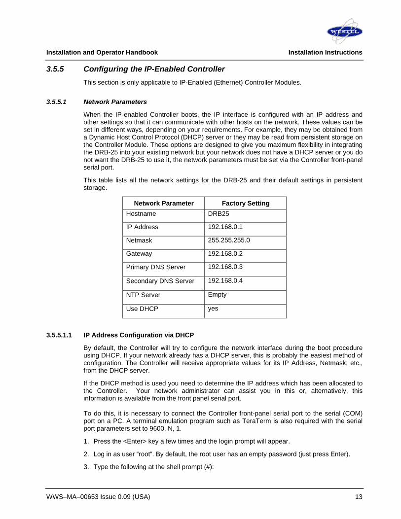
3.5.5.1 Network Parameters
When the IP-enabled Controller boots, the IP interface is configured with an IP address and other settings so that it can communicate with other hosts on the network. These values can be set in different ways, depending on your requirements. For example, they may be obtained from a Dynamic Host Control Protocol (DHCP) server or they may be read from persistent storage on the Controller Module. These options are designed to give you maximum flexibility in integrating the DRB-25 into your existing network but your network does not have a DHCP server or you do not want the DRB-25 to use it, the network parameters must be set via the Controller front-panel serial port.
This table lists all the network settings for the DRB-25 and their default settings in persistent storage.
Network Parameter Factory Setting Hostname DRB25
IP Address 192.168.0.1
Netmask 255.255.255.0
Gateway 192.168.0.2
Primary DNS Server 192.168.0.3
Secondary DNS Server 192.168.0.4
NTP Server Empty
Use DHCP yes
3.5.5.1.1 IP Address Configuration via DHCP
By default, the Controller will try to configure the network interface during the boot procedure using DHCP. If your network already has a DHCP server, this is probably the easiest method of configuration. The Controller will receive appropriate values for its IP Address, Netmask, etc., from the DHCP server.
If the DHCP method is used you need to determine the IP address which has been allocated to the Controller. Your network administrator can assist you in this or, alternatively, this information is available from the front panel serial port. To do this, it is necessary to connect the Controller front-panel serial port to the serial (COM) port on a PC. A terminal emulation program such as TeraTerm is also required with the serial port parameters set to 9600, N, 1.
1. Press the <Enter> key a few times and the login prompt will appear.
2. Log in as user “root”. By default, the root user has an empty password (just press Enter).
3. Type the following at the shell prompt (#):
Installation and Operator Handbook Installation Instructions
WWS–MA–00653 Issue 0.09 (USA) 14
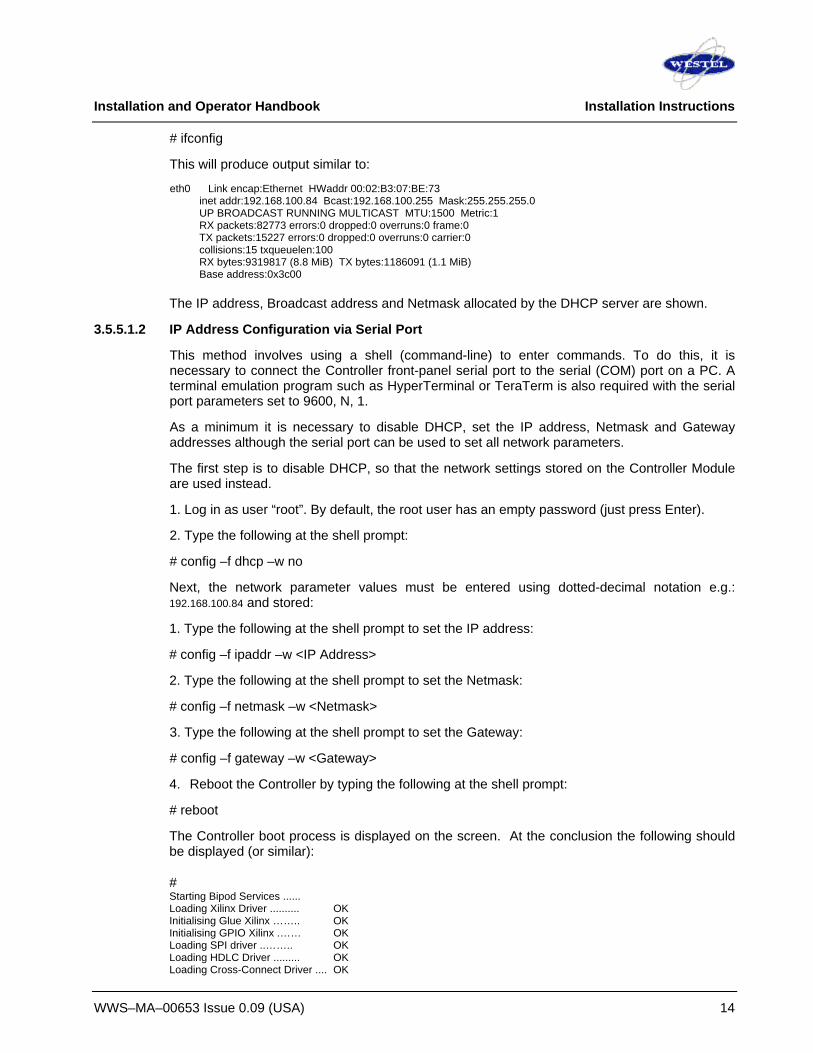
# ifconfig
This will produce output similar to:
eth0 Link encap:Ethernet HWaddr 00:02:B3:07:BE:73 inet addr:192.168.100.84 Bcast:192.168.100.255 Mask:255.255.255.0 UP BROADCAST RUNNING MULTICAST MTU:1500 Metric:1 RX packets:82773 errors:0 dropped:0 overruns:0 frame:0 TX packets:15227 errors:0 dropped:0 overruns:0 carrier:0 collisions:15 txqueuelen:100 RX bytes:9319817 (8.8 MiB) TX bytes:1186091 (1.1 MiB) Base address:0x3c00
The IP address, Broadcast address and Netmask allocated by the DHCP server are shown.
3.5.5.1.2 IP Address Configuration via Serial Port
This method involves using a shell (command-line) to enter commands. To do this, it is necessary to connect the Controller front-panel serial port to the serial (COM) port on a PC. A terminal emulation program such as HyperTerminal or TeraTerm is also required with the serial port parameters set to 9600, N, 1.
As a minimum it is necessary to disable DHCP, set the IP address, Netmask and Gateway addresses although the serial port can be used to set all network parameters.
The first step is to disable DHCP, so that the network settings stored on the Controller Module are used instead.
1. Log in as user “root”. By default, the root user has an empty password (just press Enter).
2. Type the following at the shell prompt:
# config –f dhcp –w no
Next, the network parameter values must be entered using dotted-decimal notation e.g.: 192.168.100.84 and stored:
1. Type the following at the shell prompt to set the IP address:
# config –f ipaddr –w <IP Address>
2. Type the following at the shell prompt to set the Netmask:
# config –f netmask –w <Netmask>
3. Type the following at the shell prompt to set the Gateway:
# config –f gateway –w <Gateway>
4. Reboot the Controller by typing the following at the shell prompt:
# reboot
The Controller boot process is displayed on the screen. At the conclusion the following should be displayed (or similar):
# Starting Bipod Services ...... Loading Xilinx Driver .......... OK Initialising Glue Xilinx …….. OK Initialising GPIO Xilinx .…… OK Loading SPI driver ..…….. OK Loading HDLC Driver ......... OK Loading Cross-Connect Driver .... OK

Installation and Operator Handbook Installation Instructions
WWS–MA–00653 Issue 0.09 (USA) 15
Loading STBUS Driver .......…. OK Activating Cross-Connect .......… OK Loading Codec Driver .....…… OK Loading DSP driver .....…….. OK Loading DSP program code .… OK Starting DSP .………………. OK Starting HDLC daemon ......... OK Initialising Transceivers ....… OK Configuring network ...……. OK Starting boa webserver ..... OK Starting PC Console daemon .... OK Started Bipod Services: Done. login: Once the Controller has rebooted, you can check that the new network parameters have been applied correctly by using the command:
# ifconfig
This will produce output similar to:
eth0 Link encap:Ethernet HWaddr 00:02:B3:07:BE:73 inet addr:192.168.100.84 Bcast:192.168.100.255 Mask:255.255.255.0 UP BROADCAST RUNNING MULTICAST MTU:1500 Metric:1 RX packets:82773 errors:0 dropped:0 overruns:0 frame:0 TX packets:15227 errors:0 dropped:0 overruns:0 carrier:0 collisions:15 txqueuelen:100 RX bytes:9319817 (8.8 MiB) TX bytes:1186091 (1.1 MiB) Base address:0x3c00
3.5.6 Other Configuration Settings Once the DRB-25 can be accessed via the network, the other configuration settings can be set either via the web page or via the serial port. This page shows the settings in persistent storage on the Controller. Note that these may be different to the actual network settings if DHCP is being used.

Installation and Operator Handbook Installation Instructions
WWS–MA–00653 Issue 0.09 (USA) 16
The “Store New Configuration” button writes the displayed values to persistent storage on the Controller card.
The “Apply New Configuration” button changes the Controller’s configuration to reflect those stored in persistent storage. This requires restarting the web server and other processes, and can take up to 10 seconds.
The “Reboot” button reboots the Controller (and both Transceivers, if present). The boot process takes around thirty seconds.
Installation and Operator Handbook Installation Instructions
WWS–MA–00653 Issue 0.09 (USA) 17
3.5.6.1 DNS Servers
Provision to nominate DNS servers is made although these are not required for normal IP Controller operation. If DNS servers are used it is recommended that entries are made for both Primary DNS (DNS1) and Secondary DNS (DNS2).
The DNS servers may also be entered using the front panel serial port. The command to do this is:
# config –f DNS1 –w <IP address> or
# config –f DNS2 –w <IP address>
3.5.6.2 NTP Server
NTP is the Network Time Protocol, a technique for synchronizing the time between two hosts on a network. This option can be set to the IP address or host name of a computer running an NTP server. When the option is set, the Controller will attempt to set the system time from the NTP server when the Controller boots or when the “Apply New Configuration” button is pressed.
Note that there is no real time clock on the Controller, therefore unless the system time is set when booting using this method, the system time will always be incorrect.
The NTP server may also be entered using the front panel serial port. The command to do this is:
# config –f ntp –w <IP address>
3.5.6.3 Timezone
The system time, when set using NTP, will be set in Coordinated Universal Time (UTC). To have the time displayed correctly in other time zones, this option must be set. There are two ways to do this:
• If the required time zone is within the United States, select the time zone from the drop-down list.
• Otherwise, select the entry “Custom Timezone” from the drop down box and enter a string representing the time zone. This string must be in the format specified by The Open Group Base Specifications Issue 6, IEEE Std 1003.1, 2004 Edition.
In its simplest form this format consists of a three-letter descriptive code followed by a numeric offset from UTC. For example, the time zone for Sydney, Australia, which is 10 hours ahead of UTC is utc-10. In general, the letter code is arbitrary and the time zone is completely specified by the numeric offset.
The Timezone may also be entered using the front panel serial port. The command to do this is:
# config –f timezone –w <utc+10>
3.5.6.4 Input/Output Daemon
This field can be set to “PC Console Daemon” or “Tone Remote/PSTN daemon”. The “PC Console Daemon” allows the PC Console application to connect to the DRB-25 and stream audio data between the DRB-25 and a Windows PC. The “Tone Remote/PSTN daemon” must be run when controlling a Transceiver with a tone remote unit or connecting it to the PSTN.

Installation and Operator Handbook Installation Instructions
WWS–MA–00653 Issue 0.09 (USA) 18
The Input/Output Daemon may also be set via the front panel serial port. The command options to do this are:
PC Console : # config –f iod –w <bsa>
Tone Remote/PSTN: # config –f iod –w <iac>
None : # config –f iod –w <no>
3.5.6.5 Telnet Daemon
A Telnet daemon can be run giving shell access to the Controller card. Setting this option to “Yes” will start the daemon when the Controller boots or when the “Apply New Configuration” button is pressed.
The Telnet Daemon may also be activated via the front panel serial port. The command to do this is:
# config –f telnetd –w <yes> or # config –f telnetd –w <no>
3.5.6.6 Web Login
This option determines whether a valid username and password are required to use the web interface. If set to yes, all the web pages will redirect to a login page until a valid user/password combination has been entered. The default setting is no. See Section 3.5.8 for information on creating users and setting passwords.
The Web Login may also be activated via the front panel serial port. The command to do this is:
# config –f web-login –w <yes> or # config –f web-login –w <no>
3.5.6.7 IP Console Login
This option determines whether a valid username and password are required to use the IP interface provided by the PC Console Daemon (See 3.5.6.1). If set to yes, client applications such as Westel’s PC Console will have to send a username and password when connecting to the DRB-25. The default setting is no.
The PC Console Login may also be activated via the front panel serial port. The command to do this is:
# config –f pcc-login –w <yes> or # config –f pcc-login –w <no>
3.5.7 Web Interface
3.5.7.1 Home page
The DRB-25 home page gives an overview of the Transceivers currently in the unit. If a Transceiver is present, the current channel name, current channel number, current Radio Mode and software versions are displayed.
The version number of the Controller Module software is also shown.

Installation and Operator Handbook Installation Instructions
WWS–MA–00653 Issue 0.09 (USA) 19
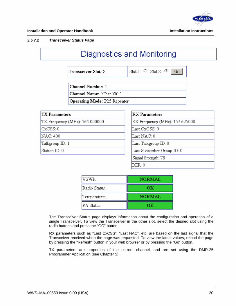
Installation and Operator Handbook Installation Instructions
WWS–MA–00653 Issue 0.09 (USA) 20
3.5.7.2 Transceiver Status Page
The Transceiver Status page displays information about the configuration and operation of a single Transceiver. To view the Transceiver in the other slot, select the desired slot using the radio buttons and press the “GO” button.
RX parameters such as “Last CxCSS”, “Last NAC”, etc. are based on the last signal that the Transceiver received when the page was requested. To view the latest values, reload the page by pressing the “Refresh” button in your web browser or by pressing the “Go” button.
TX parameters are properties of the current channel, and are set using the DMR-25 Programmer Application (see Chapter 5).

Installation and Operator Handbook Installation Instructions
WWS–MA–00653 Issue 0.09 (USA) 21
3.5.7.3 Test Signal Generation Page
The Test Signal Generation page allows the Transceiver channel to be changed and for test signals to be transmitted. The page controls one Transceiver at a time, as indicated by the radio buttons. The current channel number and channel name are shown for that Transceiver.
To change the radio channel, enter the new channel number in the input field and press the “Change Channel” button.
To transmit a test signal, select a signal from the drop-down menu, then press the “TX On ” button. The Transceiver will transmit the selected signal until the “TX Off” button is pressed. The four possible test signals are:
Standard 1101 Hz Test Tone
Hi Deviation Pattern
Low Deviation Pattern
PRBS Sequence

Installation and Operator Handbook Installation Instructions
WWS–MA–00653 Issue 0.09 (USA) 22
3.5.7.4 Feature Licensing Page
Some features on the Controller Module require a license to operate. The feature licensing page allows license strings to be added, viewed and removed.
All installed licenses are displayed. The license string, the license duration, and the specific features enabled by a license are all shown.
To add a license, copy and paste the string into the “Add license” text box and press the “Add License” button. The license information should be displayed immediately.
To remove a license, check the “Remove” checkbox corresponding to that license, then press the “Remove Licenses” button.
The Controller Module serial number is also shown, as this will be required if you wish to purchase more licenses from Westel.
3.5.7.5 Login Page
If the “Require Web Login” configuration option is set to yes, users must log in before they can use the web interface. Navigating to any page while not logged in will redirect to the login page, when a valid username and password must be entered. Once logged in, the user’s web browser will be automatically redirected to the DRB-25 home page.

Installation and Operator Handbook Installation Instructions
WWS–MA–00653 Issue 0.09 (USA) 23
3.5.8 Configuring Users and Passwords on the Controller Users and passwords must be configured at the shell (command-line) at the front-panel serial port on the Controller Module. Note that to add users, you must be logged in as the user “root”. This is the only user initially present. The root user’s password is initially empty (Enter), but should be changed to a secure password during installation.
Users can be added with the adduser command. To add a user with username “fred”:
# adduser fred
And removed with the deluser command. To delete user “fred”:
# deluser fred
Passwords can be changed with the passwd command:
# passwd fred
3.6 CONNECTIONS
3.6.1 Grounding Strap
Before connecting the DRB-25, it is recommended that a secure ground strap be connected from the grounding stud at the rear left hand side of the DRB-25 case to a substantial ground system:
1. Locate the primary grounding stud at the rear of the chassis on the lower left hand side.
2. Connect a grounding strap from an external grounding point or ground ring to the chassis primary grounding stud.
3. Ensure good electrical contact and security of all connections.
3.6.2 AC Power
An IEC standard AC power cable is provided with the AC and DC revert configurations. Connect the AC power cable as follows:
1. Set the power switch on the rear of the DRB-25 to OFF.
2. Plug-in the IEC connector of the cable to the recessed IEC plug on the rear of the DRB-25.
3. Connect the other end of the AC power cable to a properly protected and grounded AC power outlet.
3.6.3 DC Power
External DC power connection for DC and DC revert configurations is via a 2-way terminal block mounted on the rear of the DRB-25 above the mains input receptacle. Connect DC power cable as follows:
1. Ensure that DC power is not applied to the cables being connected to the DRB-25.
2. Strip back 3/8” of cable insulation on both positive and negative cables.
Installation and Operator Handbook Installation Instructions
WWS–MA–00653 Issue 0.09 (USA) 24
3. Insert positive supply into the topmost terminal (Red) and negative supply into the lower terminal (Black).
4. Secure both terminal screws and apply DC power to cable.
DC configurations include an internal fuse within the DRB-25, however to allow isolation of the unit it is recommended that a circuit breaker or DC switch is placed in the DC circuit to the DRB-25.
3.6.4 Antenna Cabling
The length and type of antenna cabling required depends on the system configuration and will be supplied separately. Connect the Transmit (N-type) and Receive (BNC type) cables to the Transmit and Receive connectors on the rear of the cabinet to the Antenna system.
3.6.5 External Interfaces
The DRB-25 supports the following external interfaces:
Transceiver Module:
• Transceiver Module audio connector
• Transceiver Module programming connector.
Controller Module
• Controller Module serial data connector
Interface Module
• Radio serial and diagnostic data for Radio 1 and Radio 2.
• Analog line connections for PSTN, PBX, Microwave or tone remote control unit.
• Ethernet connection for use as a VOIP and network management interface.
• General purpose input/output lines.
• External 10 MHz reference source input.
• Standby power to maintain temperature of reference oscillator oven during power outages.
• -48 V DC input for operation of E & M signaling interface.
3.6.5.1 Transceiver Module
3.6.5.1.1 Transceiver Module Audio Connector
Function: Connects external microphone or speaker or both to Transceiver Module Located: Transceiver Module front panel (lower connector) Connector: RJ45 Pin allocation: (Pin 1 is the top pin looking from the front of the module)
Pin Function
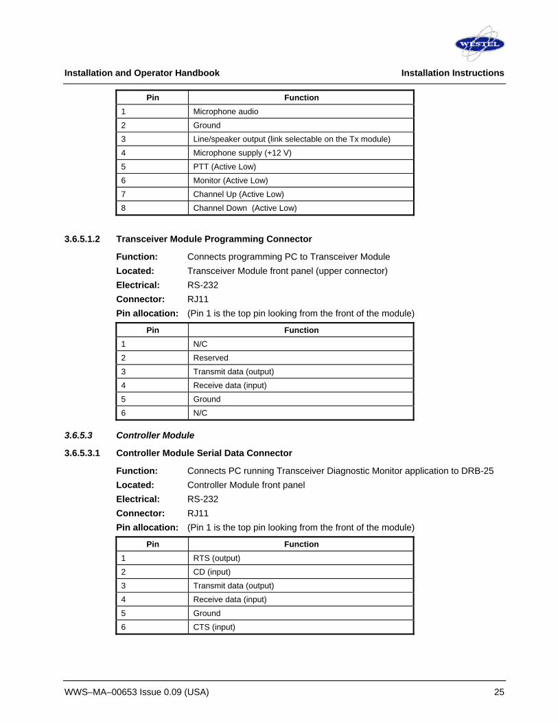
Installation and Operator Handbook Installation Instructions
WWS–MA–00653 Issue 0.09 (USA) 25
Pin Function 1 Microphone audio
2 Ground
3 Line/speaker output (link selectable on the Tx module)
4 Microphone supply (+12 V)
5 PTT (Active Low)
6 Monitor (Active Low)
7 Channel Up (Active Low)
8 Channel Down (Active Low)
3.6.5.1.2 Transceiver Module Programming Connector
Function: Connects programming PC to Transceiver Module Located: Transceiver Module front panel (upper connector) Electrical: RS-232 Connector: RJ11 Pin allocation: (Pin 1 is the top pin looking from the front of the module)
Pin Function 1 N/C
2 Reserved
3 Transmit data (output)
4 Receive data (input)
5 Ground
6 N/C
3.6.5.3 Controller Module
3.6.5.3.1 Controller Module Serial Data Connector
Function: Connects PC running Transceiver Diagnostic Monitor application to DRB-25 Located: Controller Module front panel Electrical: RS-232 Connector: RJ11 Pin allocation: (Pin 1 is the top pin looking from the front of the module)
Pin Function 1 RTS (output)
2 CD (input)
3 Transmit data (output)
4 Receive data (input)
5 Ground
6 CTS (input)

Installation and Operator Handbook Installation Instructions
WWS–MA–00653 Issue 0.09 (USA) 26
3.6.5.4 2/4W Interface Module
This section provides the interface descriptions for the 2/4W Interface Module. Interface descriptions for the 4W Interface Module are provided in section 3.6.5.5. NOTE: The 4W Interface Module has been superseded by the 2/4W version,
3.6.5.4.1 Radio Serial Data
Function: Radio Serial Diagnostic Data Located: Interface Module Label: I/O Electrical: RS-232 (one per transceiver module) Connector: DB25 (female) Pin Allocation: See 3.6.5.4.6
3.6.5.4.2 Analog Line Connection
Function: Provides line connections for PSTN, PBX, Microwave or tone remote control unit.
Located: Interface Module Label: Line One and Line Two (one per transceiver module) Electrical: See table below Connector: RJ45 Pin allocation: (Pin 1 is the lower pin on the connector)
Pin 2 wire 1 SB Lead (used only when configured)
2 M lead (used only when configured)
3 Reserved
4 Ring: DRB-25 Transmit/Receive Audio (+), balanced signal, 600R, Transmit 0 dBm (nominal), Receive -10 dBm (nominal)
5 Tip: DRB-25 Transmit/Receive Audio (+), balanced signal, 600R, Transmit 0 dBm (nominal), Receive -10 dBm (nominal)
6 Reserved
7 SG Lead (Gnd for external E/M supply)
8 E Lead (used only when configured)
Pin 4 wire 1 SB Lead
2 M lead
3 DRB-25 Receive Audio (+), balanced signal, 600R, -10 dBm (nominal)
4 DRB-25 Transmit Audio (+), balanced signal, 600R, 0 dBm (nominal)
5 DRB-25 Transmit Audio (-), balanced signal, 600R, 0 dBm (nominal)
6 DRB-25 Receive Audio (-), balanced signal, 600R, -10 dBm (nominal)

Installation and Operator Handbook Installation Instructions
WWS–MA–00653 Issue 0.09 (USA) 27
Pin 4 wire 7 SG Lead (Gnd for external E/M supply)
8 E Lead
The level of signals sent to line and received from line is adjustable using the 4 DIP switches on the Telecom Board. The following fixed steps are available: +4 dB, +8dB, +12dB and +16 dB.
3.6.5.4.3 Analog Line Jumper Settings
To select the mode of the analog line interfaces set jumpers XMA and XMB as follows:
Line 1 Line 2 2W PSTN XMA1 and XMA2-9 set to ‘PSTN’ XMB1 and XMB2-9 set to ‘PSTN’
2W leased line or 2W+E/M XMA1 and XMA2-9 set to ‘2W’ XMB1 and XMB2-9 set to ‘2W’
4W leased line or 4W+E/M XMA1 and XMA2-9 set to ‘4W’ XMB1 and XMB2-9 set to ‘4W’
The mode of operation of the E/M signaling is that when the radio squelch opens the M signaling line is connected to –48V DC active and when the E signaling line is asserted (by connection to Gnd by an external equipment) the radio PTT function is asserted.
The Interface Module can support both Type I and Type II E/M signaling. Type I signaling uses an earth return, Type II signaling uses the SB line as the return for the M signaling line and the SG line as the return for the E signaling line.
By default the module is shipped configured for Type 1 signalling.
DIP Switches

Installation and Operator Handbook Installation Instructions
WWS–MA–00653 Issue 0.09 (USA) 28
E/M Signaling – Type I Configuration
E/M Signaling – Type II Configuration
The configuration of the E/M signaling interface to Type I or Type II is set using the solder links XLA and XLB as follows:
Line 1 Line 2 Type I XLA1 : no links fitted
XLA2 : pin 1- pin 2 XLB1 : no links fitted XLB2 : pin 1- pin 2
Type II XLA1 : pin 2 – pin 3 XLA2 : no links fitted
XLB1 : pin 2 – pin 3 XLB2 : no links fitted
SG Lead
DRB-25
PTT Assert
Opto Isolated CurrentDetector
E Lead
- 48V DC
Gnd
Opto Coupler
Current Detector M Lead
- 48V DC Squelch Open
SB Lead
Gnd
DRB-25
Current Detector M Lead
Opto Coupler
Gnd
Squelch Open - 48V DC
Gnd
- 48V DC
Gnd
Opto Isolated Current Detector
E Lead
PTT Assert
Gnd

Installation and Operator Handbook Installation Instructions
WWS–MA–00653 Issue 0.09 (USA) 29
3.6.5.4.4 RS-485 serial data
Currently not implemented.
3.6.5.4.5 Ethernet
Function: Provides Ethernet connection for VOIP, Network management interface and APCO Project 25 Data Host Interface (Ed) for packet data.
Status: Available Located: Interface Module Label: NET Electrical: 10Base-T Connector: RJ45 Pin allocation: (Pin 1 is the lower pin of the connector)
Pin Function 1 Transmit data + (out of IAC)
2 Transmit data - (out of IAC)
3 Receive data + (into IAC)
4 - 5 Reserved
6 Receive data - (into IAC)
7 - 8 Reserved
3.6.5.4.6 General Purpose Input/Output Lines
Function: See descriptions below. Located: Interface Module Label: I/O Connector: DB25 (female) Function: Provides outputs for control of transmit/receive antenna change-over relays,
transmit disable inputs, Radio audio outputs, external DRB-25 reset input, Reference Backup supply input, Radio Serial Data,
Pin allocation:
Pin Function 1 Radio 1 Serial Data output
14 Radio 2 Serial Data output
2 Radio 1 Serial Data input
15 Radio 2 Serial Data input
3 Gnd
16 Gnd
4 Transmit disable input radio 1: - (active low)
17 Transmit disable input radio 2: - (active low)
5 General purpose input 3: - (active low)
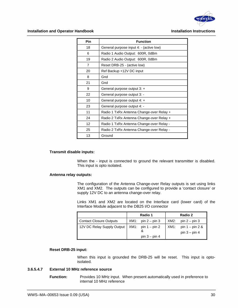
Installation and Operator Handbook Installation Instructions
WWS–MA–00653 Issue 0.09 (USA) 30
Pin Function 18 General purpose input 4: - (active low)
6 Radio 1 Audio Output: 600R, 0dBm
19 Radio 2 Audio Output: 600R, 0dBm
7 Reset DRB-25 - (active low)
20 Ref Backup +12V DC input
8 Gnd
21 Gnd
9 General purpose output 3: +
22 General purpose output 3: -
10 General purpose output 4: +
23 General purpose output 4: -
11 Radio 1 TxRx Antenna Change-over Relay +
24 Radio 2 TxRx Antenna Change-over Relay +
12 Radio 1 TxRx Antenna Change-over Relay -
25 Radio 2 TxRx Antenna Change-over Relay -
13 Ground
Transmit disable inputs:
When the - input is connected to ground the relevant transmitter is disabled. This input is opto isolated.
Antenna relay outputs:
The configuration of the Antenna Change-over Relay outputs is set using links XM1 and XM2. The outputs can be configured to provide a ‘contact closure’ or supply 12V DC to an antenna change-over relay.
Links XM1 and XM2 are located on the Interface card (lower card) of the Interface Module adjacent to the DB25 I/O connector
Radio 1 Radio 2 Contact Closure Outputs XM1: pin 2 – pin 3 XM2: pin 2 – pin 3
12V DC Relay Supply Output XM1: pin 1 – pin 2 &
pin 3 – pin 4
XM1: pin 1 – pin 2 & pin 3 – pin 4
Reset DRB-25 input:
When this input is grounded the DRB-25 will be reset. This input is opto-isolated.
3.6.5.4.7 External 10 MHz reference source
Function: Provides 10 MHz input. When present automatically used in preference to internal 10 MHz reference

Installation and Operator Handbook Installation Instructions
WWS–MA–00653 Issue 0.09 (USA) 31
Located: Interface Module (2-4W and 4W versions) Label: REF IN Electrical: Level between 450 mV peak-peak and 4v peak-peak, impedance 50 Ohm Connector: BNC Pin allocation:
Pin Function Inner External reference input
Outer Ground 3.6.5.4.8 Standby power
Function: Maintain internal reference oscillator during power outages. Located: Interface Module Label: I/O Electrical: 12 V DC (+/- 5%) input, max. current 1A Connector: See details in 3.6.5.4.6
3.6.5.4.9 -48 V DC input
Function: Provides –48 V DC input for E/M signaling Located: Interface Module Label: -48 V DC Connector: 2 pin (male) Mating plug: Phoenix Contact MSTB 1,5/2-ST-3,81 Pin allocation:
Pin Function Upper -48 V DC ground (0 V)
Lower -48 V DC input
3.6.5.5 4W Interface Module
The 4W Interface Module is discontinued. For information on this item please contact Westel.

Installation and Operator Handbook Installation Instructions
WWS–MA–00653 Issue 0.09 (USA) 32
This page left blank intentionally.

Installation and Operator Handbook Operating Instructions
WWS-MA-00654 Issue 0.05 (USA) 1
TABLE OF CONTENTS
4 OPERATING INSTRUCTIONS ................................................................................................................. 3 4.1 INTRODUCTION .................................................................................................................................... 3 4.2 SWITCHES........................................................................................................................................... 3 4.3 APPLYING POWER ............................................................................................................................... 4
4.3.1 Initial Power-On Checklist.......................................................................................................... 4 4.3.2 Power-On Faultfinding ............................................................................................................... 5 4.3.3 Fuse Replacement..................................................................................................................... 5 4.3.4 Checking System Power Supply Outputs .................................................................................. 6 4.3.5 Replacing System Power Supply............................................................................................... 6
4.4 OPERATIONAL FAULTFINDING............................................................................................................... 7 4.5 CONFIGURATION.................................................................................................................................. 7
4.5.1 Fixed Channel Operation........................................................................................................... 8 4.5.2 Scan Channel Operation............................................................................................................ 8
4.6 LOCAL OPERATION .............................................................................................................................. 8 4.6.1 Monitoring Audio ........................................................................................................................ 8 4.6.2 Making Calls .............................................................................................................................. 8 4.6.3 Changing Audio Volume ............................................................................................................ 9 4.6.4 Changing Selected Channel: ..................................................................................................... 9 4.6.5 Squelch Adjustment ................................................................................................................... 9
4.7 REMOTE OPERATION ........................................................................................................................... 9 4.8 PSTN OPERATION .............................................................................................................................. 9
4.8.1 Analog Operation ..................................................................................................................... 10 4.8.2 Project 25 Digital Operation..................................................................................................... 10 4.8.3 PSTN Timeout ......................................................................................................................... 10
LIST OF TABLES 4-1 RESET SWITCHES ...................................................................................................................….3 4-2 POWER-ON INDICATORS............................................................................................................ 4 4-3 FAULTFINDING CHART FOR POWER ON PROBLEMS............................................................. 4 4-4 FAULTFINDING CHART FOR OPERATIONAL PROBLEMS ....................................................... 6

Installation and Operator Handbook Operating Instructions
WWS-MA-00654 Issue 0.05 (USA) 2
This page left blank intentionally.

Installation and Operator Handbook Operating Instructions
WWS-MA-00654 Issue 0.05 (USA) 3
4 OPERATING INSTRUCTIONS
4.1 INTRODUCTION
After installation (as described in Chapter 3), normal operation of the DRB-25 is achieved by applying power to the DRB-25 and switching on the rear panel power switch and the Power Supply Modules.
The DRB-25 Modules will perform self-test diagnostics after power is applied. Visual indicators on the module front panels will convey the status of the DRB-25 to the Operator. If any of these visual indicators show an error or fault code, simple faultfinding procedures may identify the problem and suggest an immediate solution.
If operational checks reveal a fault in DRB-25 equipment, it may be necessary to replace it. Removal of equipment is the reverse of the installation procedure described in Chapter 3. Any faulty items should be carefully packaged and sent to an authorized repair center.
If faults are not corrected by substituting equipment at an operational level, contact the supplier or its representative.
Additional connectors on the front and back panels of selected equipment allow maintenance personnel to access functions for system configuration, operational statistics and faultfinding.
4.2 SWITCHES
There are two types of switches on the front panels of the DRB-25: power and reset switches.
If an AC supply is used with the DRB-25, there is a master power supply switch on the rear of the unit which should be turned on first. The power switches on the front panel of the Power Supply Modules are switched on next.
Recessed reset switches on the Transceiver, Controller and Interface Modules (optional) allow the equipment to be reset. Additionally the DRB-25 may be reset using an external reset line available on the 2-4W Interface Module. Table 4-1 describes each reset switch and its function.
Table 4-1 Reset Switches
Equipment Reset function Interface Module Resets all modules (accessed from rear )
Interface Module External Reset on 2-4W Interface Module Resets all modules
Controller Module Resets all modules (accessed from front)
Transceiver Module Resets the Transceiver Module (accessed from front)

Installation and Operator Handbook Operating Instructions
WWS-MA-00654 Issue 0.05 (USA) 4
4.3 APPLYING POWER
Perform the following final checks before applying power:
1. Check that the ground wires are connected to the DRB-25 primary ground from an external ground point.
2. Check that all equipment and connections are secure.
3. Ensure the power cable to the DRB-25 is plugged in securely and switch power on.
4. Switch on each Power Supply Module
Note that DC direct configurations have no power supplies or switches.
4.3.1 Initial Power-On Checklist
Refer to Table 4-2 to verify that power indications are correct. Should displays or indicators suggest a fault condition, refer to 4.3.2 before proceeding.
The DRB-25 performs a self test and warm-up routine at power-on. During this, the Controller display flashes while the Transceiver display remains blank. When the warm-up is complete, the Controller READY indicator illuminates and the display changes to an oscillating pattern. The Transceiver then tunes to its default channel and displays the channel number, and the unit is ready to operate.
At normal temperatures the Controller takes approximately one minute to warm up, however at -30°C warm-up will take up to 10 minutes.
Table 4-2 Power-on Indicators
Equipment Indicator Normal Power On Indication Power Supply Module ON Red lamp (in switch) lit
Controller Module 12 V PWR Green LED lit
Controller Module 7 V PWR Green LED lit
Transceiver Module PWR Green LED lit

Installation and Operator Handbook Operating Instructions
WWS-MA-00654 Issue 0.05 (USA) 5
4.3.2 Power-On Faultfinding
If the power-on indicators do not display normally, refer to Table 4-3 for simple faultfinding procedures. Check each indication in sequence, proceeding to the next fault only when the previous one has been eliminated.
Table 4-3 Faultfinding Chart for Power on Problems
Fault Probable Cause Recommended Action Red Lamp in Power switch of Power Supply Module not lit
Poor supply connection Check all connections to the relevant equipment.
Supply faulty Check supply for correct output of 115 V, 240 VAC or 12 / 24 VDC as appropriate.
Power fuse blown Replace fuse as detailed below.
OUTPUT lamp on Power Supply Module not lit
Power Supply Module failure
Substitute known good Power Supply Module and re-test.
7 V PWR and/or 12 V PWR lamps on Controller or Transceiver Module fail to light
System Power Supply Failure
Check outputs of System Power Supply on Backplane as detailed below. If either voltage is absent, replace System Power Supply as detailed below.
Controller Module Failure If Voltages are present, switch power off, substitute known good Controller Module and re-test.
Transceiver Module Failure
If Voltages are present, switch power off, substitute known good Transceiver Module and re-test.
Controller or Transceiver module display error code in the range E01 to E99
User serviceable failure or module failure.
See table B-1in Appendix B for likely cause and recommended action
4.3.3 Fuse Replacement
AC DRB-25 units are protected by a single fuse located on the IEC connector/switch module. To check and if required, replace the DRB-25 AC power fuse, proceed as follows:
1. Switch off all power to the DRB-25 and disconnect the Mains lead.
2. Unclip and withdraw the fuse slide immediately below the AC power connector on the IEC connector/switch module on the rear of the cabinet.
3. Remove the fuse from the slide and check the continuity using a multimeter. If the fuse is ruptured, replace with a new 205 size (20 x 5) 10 Amp cartridge fuse.
4. Fit the fuse to the slide and push the fuse slide firmly home.
DRB-25 units fitted with DC input are protected by fuses located adjacent to the DC power input connector. Each Power Amplifier Module is protected by a separate fuse.To check and, if required, replace the DRB-25 DC power fuse, proceed as follows:
1. Switch off DC power to the DRB-25.

Installation and Operator Handbook Operating Instructions
WWS-MA-00654 Issue 0.05 (USA) 6
2. Unclip and withdraw the relevant fuse slide immediately below the DC power input connector on the rear of the cabinet.
3. Remove the fuse from the slide and check the continuity using a multimeter. If the fuse is ruptured, replace with a new ¼” x 1 ¼” 20 Amp cartridge fuse.
4. Fit the fuse to the slide and push the fuse slide firmly home.
4.3.4 Checking System Power Supply Outputs
To check the presence of 7 V and 12 VDC outputs from the System Power Supply, proceed as follows:
1. Disconnect and remove the Controller and Transceiver Modules from the front of the DRB-25 cabinet.
2. Observe the position of the backplane and identify the 12 VDC and 7 VDC test points between the connectors for Transceiver 1 and the Controller
3. Connect the negative probe of a Multimeter to the 0 V test point or the DRB-25 system cabinet grounding stud.
4. Using the positive lead, probe the +12 V and +7 V test points on the backplane card for the presence of the indicated voltages ± 5%.
4.3.5 Replacing System Power Supply
If the above test indicates the lack of one or both voltage rails, replace the System Power Supply as follows:
WARNING
ENSURE ALL POWER IS SWITCHED OFF BEFORE ATTEMPTING TO WORK ON THE DRB-25..
1. Switch off all power to the DRB-25 and disconnect the Mains lead.
2. Disconnect and remove the Interface Module from the rear of the DRB-25 cabinet.
3. Disconnect and remove the antenna system RF cables from the rear of the DRB-25.
4. Remove the four Philips head screws securing the left-hand rear panel of the DRB-25.
5. Ease the panel out from the Cabinet, disconnect the two RF cables from the inside of the bulkhead connectors on the panel, and carefully lay the panel aside.
6. Remove the four Philips head screws from the right-hand rear panel of the DRB-25.
7. Ease the panel out from the DRB-25 Cabinet, disconnect the two RF cables from the inside of the bulkhead connectors on the panel, and carefully lay the panel aside.
8. Locate the 4-pin DC power connector on the backplane and disconnect.

Installation and Operator Handbook Operating Instructions
WWS-MA-00654 Issue 0.05 (USA) 7
9. Locate System Power Supply DC input power leads, trace these leads to the DC power distribution terminal block located in the area behind the right hand rear panel of the cabinet and disconnect. Note the connection points for reference during refitting.
10. Using a 9/32 inch (7 mm) hexagonal nut driver, remove the four Nyloc nuts securing the Power Supply Module to the studs on the rear of the left-hand panel and remove the Power Supply Module.
11. Refitting is a reversal of the removal procedure.
4.4 OPERATIONAL FAULTFINDING
If, during operation, the DRB-25 should fail to operate as expected, observe the status indicators and displays of the modules as described in Chapter 2. Press the RESET button of the Controller Module and the Transceiver Module and re-evaluate the condition. If this fails to clear the problem, proceed with the faultfinding detailed in Table 4-4.
Table 4-4 Faultfinding Chart for Operational Problems
Indication Probable Cause Recommended Action FAULT lamp on Controller Module lit and error code displayed
Controller Module failure
Note displayed error code on Controller Module: see Appendix B for recommended action.
FAULT lamp on Transceiver Module lit and error code displayed
Transceiver Module failure
Note displayed error code on Transceiver Module: see Appendix B for recommended action.
PA FAULT lamp on Transceiver Module lit and error code displayed
PA Module failure Note displayed error code on Transceiver Module: see Appendix B for recommended action.
DRB-25 fails to transmit SWR Error E08
Antenna System failure Check antenna system for damage and ensure correct connections.
Power Amplifier Module failure
Switch power off, substitute known good Power Amplifier Module and re-test.
DRB-25 fails to receive Antenna system failure Check antenna system for damage and ensure correct connections.
Transceiver Module failure
Switch power off, substitute known good Transceiver Module and re-test.
Failure of external interfaces
Interface Module failure Switch power off, substitute known good Interface Module and re-test.
4.5 CONFIGURATION
If all the external indications are that the DRB-25 is operational, proceed with the configuration process using the Transceiver Module Programmer application as described in Chapter 5. Once configuration has been completed, the DRB-25 can be tested in its intended system environment.
Channels may be configured as fixed channels or scan channels as described in Chapter 5.

Installation and Operator Handbook Operating Instructions
WWS-MA-00654 Issue 0.05 (USA) 8
4.5.1 Fixed Channel Operation
Fixed channels will operate according to all the parameters entered in the channel settings dialog box (see Chapter 5).
4.5.2 Scan Channel Operation
Scan channels may be set up to scan between up to eight channels. The first channel selected in the scan sequence will define the operating mode (local or remote basestation or repeater), station ID, timers, encryption, power output and source priority during all scanning. The DRB-25 will scan between the channel mode, spacing, talk group ID, receive configuration and transmit configuration of each selected channel.
The DRB-25 will scan sequentially through the selected channels, with a maximum scan rate of 2 channels per second (500ms on each channel), unless a valid signal is detected on a channel. If a valid signal is detected then the DRB-25 will remain on that channel until the call is completed, then continue scanning. The scan channel can also be programmed with additional dwell times, such that the DRB-25 will remain on the channel for the specified dwell time after the completion of a call, to allow for a return call.
4.6 LOCAL OPERATION
The DRB-25 may be operated locally by using a DTMF microphone and speaker connected to the front panel handset socket of the transceiver module. Each transceiver must have a separate speaker and microphone.
4.6.1 Monitoring Audio
In single channel configurations a loudspeaker panel may be fitted to the unit to provide a speaker and volume control (refer to 3.5.4.6). Audio may be also monitored from the Transceiver Module via an external speaker connected to the front panel RJ45 audio connector.
The speaker will monitor audio on the selected channel of the transceiver, with receive parameters as defined by the channel table entry in the Transceiver Module Programmer. In normal operation all traffic with a valid NAC (digital mode) or CTCSS/CDCSS (analog mode) will be routed to the speaker. When operating as a basestation the unit may be put into ‘monitor’ mode by keying the sequence *5* on a DTMF microphone connected to the transceiver module audio connector. In monitor mode all traffic on the receive frequency will be routed to the speaker irrespective of NAC or CTCSS/CDCSS. The DTMF key sequence *5* will revert the basestation to normal squelch mode.
Note : the DTMF key # will erase any preceding (incomplete) DTMF key sequence.
4.6.2 Making Calls
Calls may be sent from the DRB-25 using a microphone connected to the transceiver module front panel RJ45 audio connector. Calls will be broadcast with the transmit NAC and Talkgroup ID (digital mode) or transmit CTCSS/CDCSS (analog mode) of the transceiver’s current channel, as defined by the channel table entry in the Transceiver Module Programmer.

Installation and Operator Handbook Operating Instructions
WWS-MA-00654 Issue 0.05 (USA) 9
4.6.3 Changing Audio Volume
If a loudspeaker panel is fitted, audio volume is controlled by the volume knob on the panel. If an external speaker is connected, audio volume may be controlled using a DTMF microphone connected to the transceiver module front panel RJ45 audio connector. The DTMF key sequence *2*nn* will set audio volume to level ‘n’ between 00 (off) and 09 (full volume).
Note : the DTMF key # will erase any preceding (incomplete) DTMF key sequence.
4.6.4 Changing Selected Channel:
The transceiver’s current channel may be changed using a DTMF microphone connected to the transceiver module front panel RJ45 audio connector. The DTMF key sequence *1*nnn* will change the transceiver to channel ‘nnn’. The selected channel will be displayed on the front panel of the transceiver module.
Note : the DTMF key # will erase any preceding (incomplete) DTMF key sequence.
4.6.5 Squelch Adjustment
The receiver squelch level may be set in analog mode using a DTMF microphone connected to the transceiver module front panel RJ45 audio connector. The DTMF key sequence *3*nn* will change the squelch level as follows:
• *3*00* sets carrier squelch.
• *3*nn* sets squelch level to ‘nn’ dB SINAD where ‘nn’ is between 06 and 20.
• Squelch hysteresis is 2dB.
4.7 REMOTE OPERATION
The DRB-25 may be controlled remotely using any industry standard tone remote control console over two or four wire telephone lines using leased lines or dial up, provided the DRB-25 is fitted with the corresponding two or four wire line interface option. One line is used for each transceiver. To configure the DRB-25 for remote operation:
1. Connect the two or four wire line(s) to the RJ45 line socket on the interface module at the rear of the DRB-25.
2. Configure the allocation of function tones (F1 up to F12) if required (this functionality is part of the Transceiver Module Programmer software described in chapter 5).
Connect the tone remote console to the line and operate according to the console manufacturer’s instructions.
4.8 PSTN OPERATION
Remote users may use the DRB-25 to make PSTN calls from a compatible handset. The DRB-25 PSTN capability can be accessed using one of the following radios:

Installation and Operator Handbook Operating Instructions
WWS-MA-00654 Issue 0.05 (USA) 10
1. A wideband or narrow band analog radio with DTMF signaling
2. A Project 25 compatible radio supportng Project 25 PSTN Explicit Dialing messaging as described in the P25 Specification “Link Control Formats for Conventional Operation”
The DRB-25 must have a Controller Module and an Interface Module with 2/4-wire support installed to enable PSTN operation. The DRB-25 operates in full-duplex mode; subscriber units operate in half-duplex mode.
4.8.1 Analog Operation
To make a PSTN call from an analog radio, a user will follow the following procedure:
1. When on channel, a user can take the PSTN line “off hook” by keying PTT and dialing the sequence *13* into the handset.
2. Once the user releases PTT a dial tone should be heard back from the DRB-25.
3. The user can then dial the desired number and conduct a conversation.
4. At the end of the call the user will place the PSTN line “on hook” by keying PTT and dialing the sequence *14* into the handset.
4.8.2 Project 25 Digital Operation
To make a PSTN call from a P25 compatible digital radio, a user will follow the following procedure:
1. The P25 radio is programmed with a PSTN access (off-hook) code of *13*, a PSTN de-access code of *14* and the phone number (or numbers) that are required to be called. The method of doing this varies by manufacturer and the appropriate programming manual should be consulted.
2. When on channel, a user can take the PSTN line “off hook” by pressing the key programmed with the PSTN access code on the P25 radio. A dial tone should be heard back from the P25 handset.
3. Select from the programmed list the PSTN number to be dialed. Call progress tones from the PSTN should be audible in the P25 radio.
4. When the called party answers the conversation can be conducted.
5. At the end of the call the user will place the PSTN line “on hook” by pressing the appropriate de-access (on-hook) key.
4.8.3 PSTN Timeout
The DRB-25 is fitted with a PSTN timeout of 30s so that if the user loses access to the channel the DRB-25 will time out and place the PSTN line on hook.

Installation and Operator Handbook Programming and Configuration
WWS-MA-00657 Issue: 1.06 (USA) 1
TABLE OF CONTENTS
5 PROGRAMMING & CONFIGURATION .......................................................................................................3
5.1 Overview...................................................................................................................................................3
5.2 Getting Started.........................................................................................................................................3 5.2.1 System Requirements ........................................................................................................................3 5.2.2 Obtaining the DRB-25 Programmer Software....................................................................................3 5.2.3 Installing the DRB-25 Programmer Software .....................................................................................3 5.2.4 Starting DRB-25 for the First Time .....................................................................................................4 5.2.5 Connecting the Programmer to the Transceiver Module ...................................................................4 5.2.6 Getting Help........................................................................................................................................4 5.2.7 Running the DRB-25 Software ...........................................................................................................5 5.2.8 Upgrading From TMP software to DRB-25 programming software ...................................................5
5.3 Configuring Communications ................................................................................................................6 5.3.1 Serial Communications.......................................................................................................................6 5.3.2 Modem Communications....................................................................................................................7 5.3.3 Exit Binary Mode ................................................................................................................................7
5.4 Programming The Radio.........................................................................................................................7 5.4.1 Radio Wide Settings ...........................................................................................................................7 5.4.2 Channel Table ....................................................................................................................................9
5.4.2.1 Channel Selection .................................................................................................................... 10 5.4.2.2 Channel Type ........................................................................................................................... 11
5.4.2.2.1 Fixed Channel ...................................................................................................................... 11 5.4.2.2.2 Scan Channels ..................................................................................................................... 15 5.4.2.2.3 Channel Settings Dialog Box Controls ................................................................................. 15
5.4.3 Tone Remote Settings..................................................................................................................... 17 5.4.4 Encryption Settings.......................................................................................................................... 18 5.4.5 Squelch Groups............................................................................................................................... 20 5.4.6 License Features ............................................................................................................................. 21 5.4.7 Change Password ........................................................................................................................... 22
5.5 Programming Examples....................................................................................................................... 24
Installation and Operator Handbook Programming and Configuration
WWS-MA-00657 Issue: 1.06 (USA) 2
LIST OF FIGURES Figure 5-1 DRB-25 Software Main Window .........................................................................................................4 Figure 5-2 Serial Comms Dialog Box ...................................................................................................................6 Figure 5-3 Modem Commands Dialog Box ..........................................................................................................7 Figure 5-4 Radio Wide Settings Dialog Box .........................................................................................................8 Figure 5-5 Channel Table Dialog Box ..................................................................................................................9 Figure 5-6 Channel Settings Dialog Box ........................................................................................................... 10 Figure 5-7 Configure Scan Channel Reference Dialog Box.............................................................................. 15 Figure 5-8 Tone Remote Dialog Box................................................................................................................. 17 Figure 5-9 Tone Remote Properties .................................................................................................................. 18 Figure 5-10 Encryption Settings Dialog Box...................................................................................................... 19 Figure 5-11 Add Key Dialog Box ....................................................................................................................... 19 Figure 5-12 Active Squelch Groups Dialog Box ................................................................................................ 20 Figure 5-13 Squelch Groups Dialog Box........................................................................................................... 21 Figure 5-14 License Features Dialog Box ......................................................................................................... 22 Figure 5-15 Add License Dialog Box................................................................................................................. 22 Figure 5-16 Change Password Dialog Box ....................................................................................................... 22
LIST OF TABLES Table 5-1 System Requirements ..........................................................................................................................3 Table 5-2 VHF Receive/Transmit Spacing ........................................................................................................ 12 Table 5-3 UHF Receive/Transmit Spacing........................................................................................................ 12 Table 5-4 Channel Parameters and Limits........................................................................................................ 16 Table 5-5 Function Tone Frequencies............................................................................................................... 18

Installation and Operator Handbook Programming and Configuration
WWS-MA-00657 Issue: 1.06 (USA) 3
5 PROGRAMMING & CONFIGURATION
5.1 Overview
Configuration of the DRB-25 product is performed using the Windows™-based DRB-25 Programmer software application running on an IBM™ compatible PC connected via an RS-232 port (RJ-11) to the DRB-25. This manual documents the procedures for installing the DRB-25 software and its operation.
As additional features are added to the DRB-25 upgrades to the DRB-25 Programmer are released. These instructions incorporate all changes up to V2.7.
5.2 Getting Started
5.2.1 System Requirements
Table 5-1 below gives the minimum system requirements for operation of the DRB-25 programmer software application.
Table 5-1 System Requirements
Component Minimum Recommended Computer 80486 Intel Pentium at 100 MHz
Operating system Windows 95 Windows 95/98/NT/2000/XP
RAM 8 Mb 16 Mb
Hard disk free space 1.5 Mb 10 Mb
Display type VGA Super VGA
Display resolution 640 x 480 pixels 1024 x 768 pixels
5.2.2 Obtaining the DRB-25 Programmer Software
The DRB-25 software may be supplied on CD ROM or downloaded from the Westel website.
5.2.3 Installing the DRB-25 Programmer Software
The following steps assume that the DRB-25 software is being installed from a CD ROM or a diskette drive A:\ on to a hard drive.
To install the DRB-25 software application:
1. Double-click on the file “setup.exe” to commence the installation.
2. Follow the instructions given by the Setup dialog boxes.
If installation problems occur, contact Westel.

Installation and Operator Handbook Programming and Configuration
WWS-MA-00657 Issue: 1.06 (USA) 4
5.2.4 Starting DRB-25 for the First Time
To start the DRB-25 software application, select the DRB-25 icon from the Start | Programs menu.
The DRB-25 main window will appear as shown in Figure 5-1.
Figure 5-1 DRB-25 Software Main Window
5.2.5 Connecting the Programmer to the Transceiver Module
To connect to a DRB-25 Transceiver module:
1. A programming cable (Westel Part number CB-02272) is required. Connect the PC communications port to be used to the required DRB-25 Transceiver Module RJ-11 serial port connector using the programming cable.
2. Using the procedure given in Section 3.1, Serial Communications, set the PC communications port used to connect to the DRB-25 .
The DRB-25 software is now ready to read or write data to or from the DRB-25 transceiver module.
5.2.6 Getting Help
The information contained in this manual is available as on-line help as part of the DRB-25 software. To get help on the DRB-25 software, from the main menu click on the Help pull-down menu and select Contents, Search or Index as required.

Installation and Operator Handbook Programming and Configuration
WWS-MA-00657 Issue: 1.06 (USA) 5
5.2.7 Running the DRB-25 Software
There are many configuration options available to the user, some of which depend on the hardware options installed. Other parameters are operational such as the desired receive and transmit operating frequency and channel number.
Once the DRB-25 software is installed, the Main Screen provides access to the following dialog boxes:
• File: Generate a New file, Open an existing file, Save, and Save As. Other options allow the user to Print the channel table, and to Import and Export data.
• Configure: Serial Comms for selection of Serial Port, Modem Commands and Exit Binary Mode. See Section 3, Configuring Communications.
• Program: Allows user to Get and Send programming data from and to the DRB-25 transceiver and to edit DRB-25 transceiver data using Radio Wide Settings, Channel Table, Tone Remote Settings, Encryption Settings, Squelch Groups, License Features and Change Password.
• Phone: Gives the user the ability to dial up over a modem to connect to the Transceiver, and also hang up when the programming is complete.
• Help: Supplies user with on-line help documentation through Contents, Search, Using Help and About DRB-25 Programmer.
Initial or existing configuration data can be obtained in the following ways:
• File | Open: Opens a previously saved file (Will prompt user to save before overwriting currently opened file).
• File | New: Creates a new file via user input dialog boxes.
• Program | Get: Gets the current file from a Transceiver Module (Will prompt user to save before overwriting open file).
It is possible to send data to the transceiver module by using the Program | Send option. Note that the DRB-25 software will reboot the transceiver module after sending the programming information in order to invoke the new configuration.
5.2.8 Upgrading From TMP software to DRB-25 programming software The DRB-25 Radio Programmer has new features not available in the TMP programmer. If DRB-25 Radio Programmer is used to upload channel table data that was programmed into a transceiver with TMP, the data elements describing the new features will be uninitialised, and may need manual editing afterward. By following the procedure below you can avoid the need for manual editing when upgrading to the DRB-25 Radio Programmer.
DRB-25 Radio Programmer Upgrade procedure:
Step 1 - Transceivers with channel tables that were programmed with TMP should be read back with TMP and the BCF file saved to disk. You can skip this step if you already have a saved BCF file.

Installation and Operator Handbook Programming and Configuration
WWS-MA-00657 Issue: 1.06 (USA) 6
Step 2 - Load the BCF file into DRB-25 software using the File->Open menu items. When loading the file, the DRB-25 will set the new features to the default (disabled) state. The new features, in the Channel Settings dialog are: Channel Name, Squelch System, Squelch Group, CDCSS Invert, Autosense TX, Courtesy Tone Tail. See section 5.4.1.
Step 3 - If you wish to use any of the new features, update their settings in the Channel Settings dialog . Particularly check the PTT Delay setting if you enable it, because the format has changed.
Step 4 - The BCF file is now ready to be written back to the Transceiver, or saved to disk.
5.3 Configuring Communications
The Configure pull-down menu allows the DRB-25 programmer to control the PC's serial port and interface to a modem if desired.
5.3.1 Serial Communications
To set or select the communications port, from the main menu activate the Configure pull-down menu and select Serial Comms. The Serial Comms dialog box will appear as shown in Figure 5-2.
Select desired port and click OK.
There may be an instance where the serial port is required by another PC application. If so, click RELEASE so that the other application may use the serial port, without needing to quit the DRB-25 Programmer.
NOTE
Some functions within the DRB-25 Programmer will not work correctly without serial communications to the transceiver. If in doubt, leave the serial communication port connected to the DRB-25 Programmer.
Figure 5-2 Serial Comms Dialog Box

Installation and Operator Handbook Programming and Configuration
WWS-MA-00657 Issue: 1.06 (USA) 7
5.3.2 Modem Communications
Consult your modem manual to determine what it requires for initialisation string, dial string, and hangup string. To set the modem commands used by the DRB-25 Programmer, select the Configure pull-down menu and select Modem Commands. The Modem Commands dialog box will appear as shown in Figure 5-3.
Init: The modem initialization string stores parameters to configure the modem after power up.
Dial: The modem command required before dialing a number.
Hangup: The command required to hang up the modem.
Figure 5-3 Modem Commands Dialog Box
5.3.3 Exit Binary Mode
Configure/Exit Binary Mode: When issuing a File/Send or File/Get command, the PC to DRB-25 communication mechanism on the DRB-25 uses a binary mode. On a failed File/Send or File/Get order, the DRB-25 may be left in binary mode. The Configure/Exit Binary Mode menu item will, when selected, will force the DRB-25 back into normal operating mode.
5.4 Programming The Radio
5.4.1 Radio Wide Settings
The Radio Wide Settings dialog box is accessed via Program | Radio Wide Settings. This dialog box contains general DRB-25 Transceiver parameters as shown in Figure 5-4.
• Front panel audio enable and volume adjustment.
Note: This parameter adjusts the audio levels sent to the transceiver front panel RJ45 connector. Settings made here will have no effect on audio sent to any front panel speaker connected internally to the DRB-25
• Select the default power-up channel either from the BOX_ID setting (see Appendix A) or a predetermined channel number.

Installation and Operator Handbook Programming and Configuration
WWS-MA-00657 Issue: 1.06 (USA) 8
Figure 5-4 Radio Wide Settings Dialog Box
The radio wide settings of the currently open file will be displayed.
To enter Front Panel Audio parameters:
1. Audio On or Off. Point and click as required to enable or disable audio output to the DRB-25 front panel audio connector.
2. Audio Level. Click the up or down buttons to select an audio volume level from 0 to 10.(maximum)
To enter the Back Panel Output parameters:
Diagnostic Data. Point and click as required to enable or disable diagnostic data output to the DRB-25 back panel (Interface Module).
P25 GPS Data. Point and click as required to enable or disable P25 GPS data output to the DRB-25 back panel (Interface Module).
If the settings are acceptable, click OK, otherwise click Cancel to close the Radio Wide Settings dialog box and the current configuration will not be changed.
Help: Provides access to On-line help for the General Settings dialog box.
To enter the default power-up channel:
1. Click the up or down buttons to select a default power up channel either derived from the BOX_ID setting (see Appendix A) or another channel.

Installation and Operator Handbook Programming and Configuration
WWS-MA-00657 Issue: 1.06 (USA) 9
If the settings are acceptable, click OK, otherwise click Cancel to close the Radio Wide Settings dialog box and the current configuration will not be changed.
5.4.2 Channel Table
To enter the Channel Table, from the main menu activate the Program pull-down menu and select Channel Table. The Channel Table dialog box will appear as shown in Figure 5-5.
The table window lists the currently configured channels for the DRB-25 Transceiver. These channels are sorted in ascending order of the channel number. Listed functions are:
Add: To add a new channel configuration, click ADD and the Channel Settings Dialog Box appears.
Delete: To delete a currently configured channel, highlight the desired channel (left mouse button click on the channel name) and click DELETE. Several channels may be deleted in one operation, if required.
Copy: To copy a configured channel, highlight the desired channel (left mouse button click on the channel name) and click COPY. The Copy Channel Dialog Box appears. Enter the new desired channel number and click OK. If the desired channel number already exists, a new Copy Channel Dialog Box appears asking if you want to replace the existing configured channel. Click YES to do so. At any stage click CANCEL to exit the Copy Channel function and return to the Channel Table Dialog Box. The new channel appears in the Channel Table Dialog Box.
Edit: To edit an existing channel, highlight the required channel (left mouse button click on the channel name) and click EDIT or double click the left mouse button. The Channel Settings Dialog Box appears and the channel parameters may be changed.
Close: This closes the Channel Table and returns to the Main Entry Screen of the DRB-25 Programmer.
Figure 5-5 Channel Table Dialog Box
To enter the Channel Settings, either Edit an existing channel or Add a channel from the Channel Table Window. The Channel Settings dialog box will appear as shown in Figure 5-6.

Installation and Operator Handbook Programming and Configuration
WWS-MA-00657 Issue: 1.06 (USA) 10
The channel settings for the selected channel will be displayed in this dialog box.
Figure 5-6 Channel Settings Dialog Box
5.4.2.1 Channel Selection
Channel Name: The name of the selected channel is shown in the Channel Name window. The channel name can be changed by overwriting the existing name in the window. The name is limited to 8 characters in length.
Channel Number: The channel number is displayed in the Channel Number window. When a channel is created with the Add command, a sequential default channel number appears here and may be edited. The channel number of established channels may not be edited.

Installation and Operator Handbook Programming and Configuration
WWS-MA-00657 Issue: 1.06 (USA) 11
5.4.2.2 Channel Type
A channel can function as either a Fixed Channel or a Scan Channel. A Fixed Channel is a “real” channel used to transmit and receive voice messages. A Scan Channel holds a list of Fixed Channels through which the radio will scan in receive mode. The channel type is selected by clicking the “Fixed” or “Scan” radio button in the “Channel Type” box.
5.4.2.2.1 Fixed Channel
Mode: Click as required to select the operating mode for the channel between basestation and repeater. In repeater mode, all valid inbound signals are repeated on the outbound channel. In base-station mode, valid inbound signals are not repeated.
Control: There are four functions/options that may be selected: Local control, Tone control, Line control and None.
Local control: Is via a DTMF microphone connected to the DRB-25 Transceiver Module audio connector (elsewhere, this is described as the front panel connector). DTMF tones can be used to configure/control the radio.
Tone control: Is via an industry standard tone remote control unit connected to the DRB-25 Interface Module line connector. Tone remote tones are used to control the radio.
Line control: Uses the rear panel audio port for control but disables tone remote signalling. When a 4-wire interface is used, control is achieved by E+M signalling. When a 2-wire interface is used, the radio is capable of making and receiving PSTN calls. In this mode call setup, dialing and cancellation is controlled by the subscriber radio using DTMF or Project 25 signaling.
None: No control option is active.
NOTE
Control options are only available on DRB-25 units fitted with a Controller Module. Control options will be ignored by DRB-25 units which have a Repeater Module installed.
Signal Type: Select the channel mode from the list of Analog, Project 25 and Autosense modes.
Bandwidth: This setting determines the peak deviation of the transmitted signal, and the channel bandwidth used in the receiver. Select the required channel bandwidth from the list, to set wideband or narrowband analog or autosense operation. Wideband operation should be selected for use with analog systems employing 25 kHz or 30 kHz channel spacing. Narrowband operation should be selected for use with analog systems employing 12.5 kHz or 15 kHz channel spacing.
Squelch System: Select the type of analog squelch required between CTCSS and CDCSS.
Group Enable: When selected, the squelch system selection is disabled and a Squelch Group is required.

Installation and Operator Handbook Programming and Configuration
WWS-MA-00657 Issue: 1.06 (USA) 12
Squelch Group: Select from a list of Squelch Groups, which are defined in Program/Squelch Groups see section 4.5 Squelch Groups. The Squelch System will determine which analog squelch is used in a squelch Group.
Link Radio: Select to enable the Transceiver Module for cross-band and cross-mode operation. This selection will be disregarded by the transceiver if it is not licensed to support Link Radio. See Section 4.6 License Features.
Enable Front Panel PTT: Select to permit transmissions to be made from the microphone connected to the DRB-25 Transceiver Module Front Panel audio connector.
NOTE
Link Radio cannot be selected when Enable Front Panel PTT is enabled and vice-versa.
Half Duplex: When half-duplex mode is selected, the receiver is disabled when transmitting and vice-versa. Half-duplex operation is only available in base-station mode.
Receive/Transmit Configuration
Freq (MHz): Enter the receive and transmit frequency for the selected channel. Note that the VHF radio frequencies can be set to 1Hz precision. However for the UHF radio, entered frequencies are internally rounded to a multiple of 5.0 kHz or 6.25 kHz (whichever is nearer) regardless of what is displayed or entered in the frequency dialog.
When the DRB-25 is operated in full duplex (simultaneous reception and transmission) isolation is required between the receive and transmit signals to ensure that the receiver is not de-sensed by the transmitter. The isolation is generally provided by a separate antenna or external RF combining network. Table 5-2 and Table 5-3 show the minimum and recommended isolation levels for VHF and UHF-Lo respectively.
Table 5-2 VHF Receive/Transmit Spacing
Receive/Transmit Spacing Minimum Isolation
Recommended Isolation
<600 kHz - Not recommended
600 kHz to 1 MHz 85 dB >100 dB
1 MHz to 2.5 MHz 70 dB >80 dB
>2.5 MHz 60 dB 80 dB
Table 5-3 UHF Receive/Transmit Spacing
Receive/Transmit Spacing Minimum Isolation
Recommended Isolation
<1 MHz - Not recommended
1 MHz to 2.5 MHz TBA TBA
>2.5 MHz TBA TBA

Installation and Operator Handbook Programming and Configuration
WWS-MA-00657 Issue: 1.06 (USA) 13
Due to harmonics of internal clocks and oscillators degradation of receiver sensitivity may be experienced on the following specific frequencies, and these frequencies should therefore be avoided:
140.000000 MHz, 150.000000 MHz, 157.287500 MHz, 160.000000 MHz and 170.000000 MHz.
NAC (Network Access Code). For Project 25 / Autosense operation select the NAC as required, using hexadecimal (Hex) notation. Receive and transmit NAC may be set independently, or the transmit NAC may be set to be the same as the received NAC (‘Same as Rx’). If analog channel mode is selected then these boxes will be disabled. Click on the Up/Down Arrows to increase/decrease the current NAC value.
The DRB-25 radio can be programmed to un-mute on any NAC by using the ‘ANY’ value or by entering the NAC values 0xF7E and 0xF7F as defined in the Project 25 suite of standards.
CxCSS: Receive and transmit CxCSS may be set independently or the transmit CxCSS may be set to be the same as the received CxCSS (‘Same as Rx’). If APCO 25 channel mode is selected then this box will be disabled. Click on the Up/Down Arrows to increase/decrease the current CxCSS value.
CDCSS Invert: Select to invert the CDCSS encoding string pattern for both receive and transmit.
Force Autosense TX: Selects the Transmit type (Analog or Digital) when a PTT from the front panel microphone or rear panel 4w/2w interface has been asserted on a channel whose signal type has been programmed as "Autosense".
Note that Force Autosense TX does not operate in Link Radio mode where a second transceiver is transmitting as a result of the squelch opening on the first. In this scenario the transmit mode of the second transceiver is determined by the transmit values entered for the NAC and/or CxCSS.
Link Radio “Tx AS Rx”: when two repeaters are linked in Link Radio mode, the linked transmitter will use the same CTCSS/CDCSS/NAC parameters as are received by the receiver.
Encryption: The DRB-25 will repeat P25 transmissions using the DES-OFB and AES algorithms.
Algorithm ID: The DRB-25 Programmer currently supports encryption and decryption of transmissions using the DES-OFB algorithm, however, restrictions relating to the export of cryptographic devices and technology may mean that the DRB-25 may not be fitted with encryption capability. Check with Westel for more detail relating to encryption services in the DRB-25.
Key ID: The Key ID may be a number between 0x0000 and 0xffff.
See Section 5.4.4 Encryption Settings for details.

Installation and Operator Handbook Programming and Configuration
WWS-MA-00657 Issue: 1.06 (USA) 14
Timers
PTT Tail (sec): Enter the amount of time the DRB-25 continues to transmit a carrier signal after the Press To Talk is released, or click on the up/down arrows to raise or lower the Tail time in 0.1 second increments to a maximum of 9.9 seconds.
PTT Delay (msec): (Applicable to Base-station Mode only) Enter the amount of time the Tx/Rx changeover relay is allowed to stabilize before RF power is applied, or click on the up/down arrows to raise or lower the Delay time in 1 millisecond increments to a maximum of 99ms. Set to zero if no changeover relay is used.
PTT Timeout (sec): Enter the maximum duration of continuous transmission in seconds, or click on the up/down arrows to raise or lower the Timeout in 1 second increments to a maximum of 255 seconds. If no transmission length timer is required, set to zero.
Courtesy Tone
Courtesy tone is only applicable in repeater mode. In analog mode a choice of tone frequency is available and in digital mode a 1kHz (nominal) tone is available. In autosense modes only an analog tone is available.
Tail (sec): Enter the desired duration of the courtesy tone to follow analog voice transmissions initiated from the front panel microphone or rear panel 2w/4w interface, or click on the up/down arrows to raise or lower the Tail time in 10 millisecond increments to a maximum of 9.99s.
For digital P25 mode a minimum tail of 180ms is transmitted regardless of the duration entered.
Tone (Hz): For analog modes there are four options available, None, 400Hz, 1000Hz and 2500Hz.
Reverse Burst: Reverse Burst is a feature designed to minimize the squelch crash at the end on an analog transmission. If the reverse burst check box is selected in an analog transmit mode then at the end of a transmission the CTCSS tone phase will be inverted for CTCSS channels or the CDCSS "turn-off" signal will be transmitted for CDCSS channels as described in TIA/EIA 603. When this box is selected, the Courtesy Tone tail setting determines the burst length, and Tone setting is ignored. The tail time should be selected to optimize the performance of the particular analog mobile used in a system.
General
Talk Group ID: Select or enter the Talk Group ID for Project 25 transmissions from the DRB-25 in basestation mode.
Unit ID: Select Unit ID for the Base-station Unit.
Power (Watts): Enter the transmit output power for the channel or click on the up/down arrows to raise or lower the output power. Increments of 1W are available and the actual resolution is in approximately 1dB increments.
NOTE: The Power level data is stored and managed in the PA module As such, up to 30 seconds may elapse after configuration changes or radio startup before this setting

Installation and Operator Handbook Programming and Configuration
WWS-MA-00657 Issue: 1.06 (USA) 15
becomes active. During this time, the transmitter, if keyed, will transmit at full power for up to a few seconds while the PA is characterized at the frequency and power level selected.
Squelch levels: The squelch maybe programmed with a value of 0- 15. A setting of 0 corresponds to an open squelch condition.
A setting of 4 corresponds to an approximate SINAD of 9dB and a setting of 7 corresponds to an approximate SINAD of 12dB.
When programmed as a scan channel the squelch setting is taken from the value in the first channel in the scan list.
5.4.2.2.2 Scan Channels
A scan channel consists of two or more fixed channels. The DRB-25 will step through the list of fixed channels until it finds one with a valid receive signal. The Channel Settings Dialog Box displays a list of fixed channels with their dwell times. Use the Add, Edit and Delete buttons to manage this list.
Add: Adds a reference channel to the selected scan channel list using the Configure Scan Channel Reference Dialog Box shown in Figure 5-7. Select a fixed channel in the Reference Channel field and nominate a Dwell Time. Dwell Time is the period, in seconds, for which the DRB-25 will monitor a particular reference channel given ceased activity on that channel. The selected reference channel is then added to the scan channel when the OK button is clicked or discarded if the Cancel button is clicked.
Edit: Changes the parameters of a pre-configured fixed channel.
Delete: Deletes the highlighted reference channel from the Scan Channel list.
Note that due to the structure of the data format digital channels will require a longer dwell time than analog channels.
Figure 5-7 Configure Scan Channel Reference Dialog Box
5.4.2.2.3 Channel Settings Dialog Box Controls
OK: Returns to the Channel Table Dialog Box, updating the parameters of the selected channel.
Cancel: Returns to the Channel Table Dialog Box, without changing the parameters of the selected channel.

Installation and Operator Handbook Programming and Configuration
WWS-MA-00657 Issue: 1.06 (USA) 16
Table 5-4 Channel Parameters and Limits
Parameter Range Channel Selection Channel 0 to Channel 511 as defined in Program/Channel Table
Channel Type Fixed or scan
Signal Type Project 25, Analog FM (CTCSS or CDCSS), Autosense (Project 25 and Analog)
Channel Mode Basestation or Repeater.
Spacing Wide or Narrow band
Frequency in MHz VHF 136-174 MHz or UHF 380-520 MHz.
Network access code (NAC)
Receive :3 digit hexadecimal or ‘ANY’ per TIA102.BAAC Transmit : 3 digit hexadecimal, or ‘same as receive’ per TIA102.BAAC
CxCSS Receive : Tones and codes according to TIA 603, or ‘any’ Transmit : Tones and codes according to TIA 603, ‘none’ or ‘same as receive’
Talk group ID 4 digit hexadecimal 0x0001 to 0xFFFF (All Talk-groups)
Encryption algorithm DES–OFB or None
Encryption key ID Up to 16 key IDs (labeled 0x0000 to 0xFFFF) as defined in Program/Encryption Settings
Control mode Repeater or Basestation [Basestation local control, Basestation tone control, Line control, None (no control), Network and FSIAP]
Disable front panel PTT Enabled/Disabled
Link radio Enabled/Disabled
Unit ID 0 through to 0xFFFFFF
PTT Timeout 0 to 255 seconds
PTT Tail 0.0 to 9.9 seconds
PTT Delay 0.0 to 0.099 seconds
Courtesy Tail 0.00 to 9.99 seconds
Courtesy Tone None/400Hz/1000Hz/2500Hz
Power 50 Watt Power Amplifers : 5 to 50 W 100 Watt Power Amplifiers : 10 to 100 W
Number of Referenced Channels within a Scan Channel
1 to 8 fixed channels
Dwell time 0.0 to 9.9 seconds

Installation and Operator Handbook Programming and Configuration
WWS-MA-00657 Issue: 1.06 (USA) 17
5.4.3 Tone Remote Settings
Using the Tone Remote Properties the following functions may be allocated to tones used by industry standard tone remote units:
• Increase audio level
• Decrease audio level
• Change to Tone Remote controlled channel
Selecting Program/Tone Remote Settings, the Tone Remote Settings Dialog Box will appear as shown in Figure 5-8. This box lists the currently configured tone signals with their appropriate function.
Figure 5-8 Tone Remote Dialog Box
Add: When selected, the Tone Remote Properties appears as shown in Figure 5-9. Select a function tone (F1 – F12). When assigning a function, the pull-down window lists the appropriate channels, (eg. Fixed channels with Tone control are assigned as tone remote channels) and increase/decrease audio level functions. Choose a function and click OK. The new function will now be displayed in the Tone Remote Settings Dialog Box. Otherwise click CANCEL and the Tone Remote Settings will remain unchanged.
Edit: To edit a particular Tone Remote function from the Tone Remote Settings Dialog Box, either highlight the appropriate function and click EDIT or simply double click the function. This will display the Tone Remote Properties Dialog Box containing the functions current properties.
Delete: To delete a particular tone remote function, highlight the required function and click DELETE.
When satisfied with the tone remote function settings, click OK. Otherwise, click CANCEL to ignore changes.
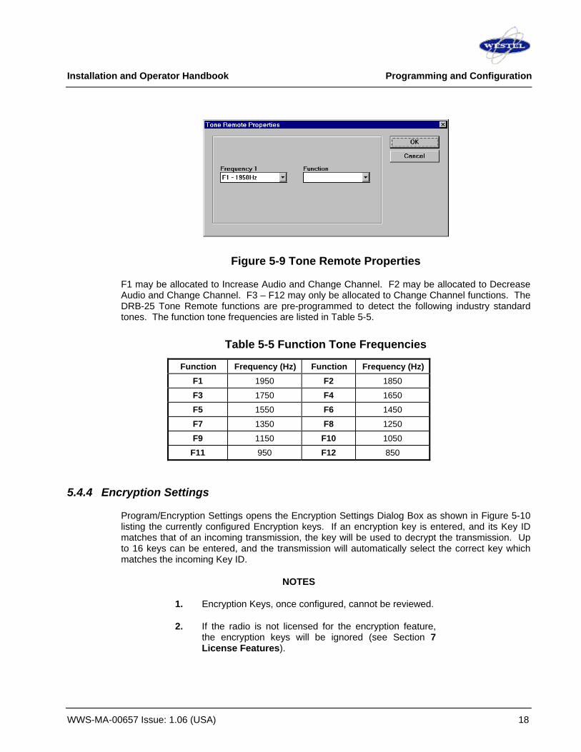
Installation and Operator Handbook Programming and Configuration
WWS-MA-00657 Issue: 1.06 (USA) 18
Figure 5-9 Tone Remote Properties
F1 may be allocated to Increase Audio and Change Channel. F2 may be allocated to Decrease Audio and Change Channel. F3 – F12 may only be allocated to Change Channel functions. The DRB-25 Tone Remote functions are pre-programmed to detect the following industry standard tones. The function tone frequencies are listed in Table 5-5.
Table 5-5 Function Tone Frequencies
Function Frequency (Hz) Function Frequency (Hz) F1 1950 F2 1850
F3 1750 F4 1650
F5 1550 F6 1450
F7 1350 F8 1250
F9 1150 F10 1050
F11 950 F12 850
5.4.4 Encryption Settings
Program/Encryption Settings opens the Encryption Settings Dialog Box as shown in Figure 5-10 listing the currently configured Encryption keys. If an encryption key is entered, and its Key ID matches that of an incoming transmission, the key will be used to decrypt the transmission. Up to 16 keys can be entered, and the transmission will automatically select the correct key which matches the incoming Key ID.
NOTES
1. Encryption Keys, once configured, cannot be reviewed.
2. If the radio is not licensed for the encryption feature, the encryption keys will be ignored (see Section 7 License Features).

Installation and Operator Handbook Programming and Configuration
WWS-MA-00657 Issue: 1.06 (USA) 19
Figure 5-10 Encryption Settings Dialog Box
To Add an Encryption Key click ADD and the Add Key Dialog Box appears as shown in Figure 5-11. The required key is entered into the eight 2-hex-digit boxes using the Tab key to move between boxes. Note that each 2-hex-digit code must have odd parity. The DRB-25 programmer will check and report any errors of the entered encryption key. Next, enter a Key ID between 0x0000 and 0xFFFF. When the desired Encryption Key and Key ID are entered, click OK and the new key will be listed in the Encryption Settings Dialog Box.
For testing purposes a key of (Hex) 70 70 70 70 70 70 70 70 is often used.
Clear Key: In the Add Key Dialog Box, an entered key can be cleared by clicking the Clear Key button.
Generate Random Key: To add a random key, click Generate Random Key button and assign a Key ID.
At any stage, the CANCEL button can be clicked and the key will not be added to the list.
Delete: To delete an existing Encryption Key, highlight the desired key and click DELETE.
Close: When satisfied with the list of Encryption Keys, click CLOSE in the Encryption Settings Dialog Box.
Figure 5-11 Add Key Dialog Box

Installation and Operator Handbook Programming and Configuration
WWS-MA-00657 Issue: 1.06 (USA) 20
5.4.5 Squelch Groups
Program/Squelch Groups will display the Active Squelch Groups Dialog Box as shown in Figure 5-12. This lists the currently configured Squelch Groups. Groups of squelch tones are used to allow a repeater to retransmit a signal containing any one of a number of different squelch tones or codes.
Figure 5-12 Active Squelch Groups Dialog Box
Add: To add a squelch group, click ADD and the Squelch Group Properties Dialog Box appears as shown in Figure 5-13. Enter a name for the new squelch group in the Squelch Group Name Field. Then, by clicking the up/down arrows, select the desired squelch value for the squelch system and click the appropriate Left Arrow to add the selection to the list.
NOTE
Multiple values for the same squelch system, and multiple squelch systems, with the exception of the CDCSS and CTCSS case, can co-exist in the same squelch group. The DRB-25 radio will use the appropriate values in the group for the selected channel.
Items within the list can be deleted by highlighting the desired item and clicking DELETE. When satisfied with the list click OK and the new list is entered as a new squelch group and displayed in the Active Squelch Groups Dialog Box. Alternatively, click CANCEL and all additions and/or changes are ignored.
Edit: Squelch groups can be edited by either double clicking on the appropriate group or by highlighting the group and clicking EDIT. The Squelch Group Properties Dialog Box displays the configuration of the selected group where items can be added, altered or deleted as required.
Delete: Existing squelch groups can be deleted by highlighting the required group and clicking DELETE.
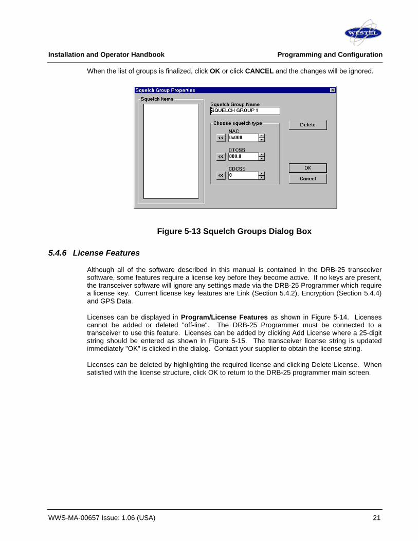
Installation and Operator Handbook Programming and Configuration
WWS-MA-00657 Issue: 1.06 (USA) 21
When the list of groups is finalized, click OK or click CANCEL and the changes will be ignored.
Figure 5-13 Squelch Groups Dialog Box
5.4.6 License Features
Although all of the software described in this manual is contained in the DRB-25 transceiver software, some features require a license key before they become active. If no keys are present, the transceiver software will ignore any settings made via the DRB-25 Programmer which require a license key. Current license key features are Link (Section 5.4.2), Encryption (Section 5.4.4) and GPS Data.
Licenses can be displayed in Program/License Features as shown in Figure 5-14. Licenses cannot be added or deleted "off-line". The DRB-25 Programmer must be connected to a transceiver to use this feature. Licenses can be added by clicking Add License where a 25-digit string should be entered as shown in Figure 5-15. The transceiver license string is updated immediately "OK" is clicked in the dialog. Contact your supplier to obtain the license string.
Licenses can be deleted by highlighting the required license and clicking Delete License. When satisfied with the license structure, click OK to return to the DRB-25 programmer main screen.
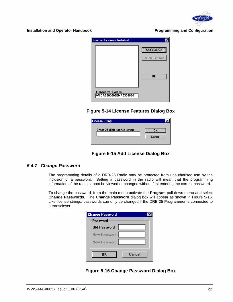
Installation and Operator Handbook Programming and Configuration
WWS-MA-00657 Issue: 1.06 (USA) 22
Figure 5-14 License Features Dialog Box
Figure 5-15 Add License Dialog Box
5.4.7 Change Password
The programming details of a DRB-25 Radio may be protected from unauthorised use by the inclusion of a password. Setting a password in the radio will mean that the programming information of the radio cannot be viewed or changed without first entering the correct password.
To change the password, from the main menu activate the Program pull-down menu and select Change Passwords. The Change Password dialog box will appear as shown in Figure 5-16. Like license strings, passwords can only be changed if the DRB-25 Programmer is connected to a transciever.
Figure 5-16 Change Password Dialog Box

Installation and Operator Handbook Programming and Configuration
WWS-MA-00657 Issue: 1.06 (USA) 23
Enter the old password, followed by the desired new one. If no password is currently set, leave the “Old Password” field empty. Enter the new password again in the bottom field for verification and click OK. The Tab key may be used to move between the text boxes. To remove the password from the radio, enter the old password in the “Old Password” field and leave the “New Password” fields empty.
Transceivers are shipped with the default password “1234”. If the DRB-25 Programmer prompts for a password unexpectedly, try “1234”. If you forget the password for a radio, contact Westel.

Installation and Operator Handbook Programming and Configuration
WWS-MA-00657 Issue: 1.06 (USA) 24
5.5 Programming Examples The following table shows example programming for commonly used channel types:
Channel Number 0 1 2 3 4 5
Channel Name U_link_N V_link_N U_link_W V_link_W U_link_P V_link_P
Mode Narrowband FM Narrowband FM Wideband FM Wideband FM APCO 25 APCO 25
TX Frequency 462.250 162.275 462.250 162.275 462.250 162.275
RX Frequency 452.750 157.625 452.750 157.625 452.750 157.625
Squelch System CTCSS CTCSS CTCSS CTCSS CTCSS CTCSS
TX NAC 0x293 0x293 0x293 0x293 0x293 0x293
RX NAC 0x293 0x293 0x293 0x293 0x293 0x293
TX CxCSS 131.8 131.8 131.8 131.8 131.8 131.8
RX CxCSS 131.8 131.8 131.8 131.8 131.8 131.8
CDCSS Invert No No No No No No
Operational Mode Basestation Basestation Basestation Basestation Basestation Basestation
Control Local Local Local Local Local Local
Front Panel PTT Off Off Off Off Off Off
Link Radio On On On On On On
TX Key ID 0x0000 0x0000 0x0000 0x0000 0x0000 0x0000
TX Algorithm ID No Encryption No Encryption No Encryption No Encryption No Encryption No Encryption
Talkgroup ID 0x0001 0x0001 0x0001 0x0001 0x0001 0x0001
Power (Watts) 50 100 50 100 50 100
PTT Delay (s) 0.000 0.000 0.000 0.000 0.000 0.000
PTT Tail (s) 0.0 0.0 0.0 0.0 0.0 0.0
PTT Timeout (s) 0 0 0 0 0 0
Courtesy Timer (s) 0.00 0.00 0.00 0.00 0.00 0.00
Courtesy Tone None None None None None None
Half Duplex On On On On On On
Unit ID 0x000000 0x000000 0x000000 0x000000 0x000000 0x000000
Reverse Burst Off Off Off Off Off Off
Autosense TX Analog Analog Analog Analog Analog Analog

Installation and Operator Handbook Programming and Configuration
WWS-MA-00657 Issue: 1.06 (USA) 25
Channel Number 6 7 8 9 10 11
Channel Name VHF Tone UHF Tone VHF_WB UHF_WB VHF_P25 UHF_P25
Mode Wideband FM Wideband FM Wideband FM Wideband FM APCO 25 APCO 25
TX Frequency 162.225 462.250 164.875 462.250 164.875 462.250
RX Frequency 157.625 452.750 155.125 452.750 155.125 452.750
Squelch System CTCSS CTCSS CTCSS CTCSS CTCSS CTCSS
TX NAC 0x000 0x000 0x000 0x000 0x293 0x293
RX NAC 0x001 0x001 0x001 0x001 0x293 0x293
TX CxCSS 000.0 000.0 000.0 000.0 000.0 000.0
RX CxCSS Any Any Any Any 000.0 000.0
CDCSS Invert No No No No No No
Operational Mode Basestation Basestation Repeater Repeater Repeater Repeater
Control Tone Rmt Tone Rmt Local Local Local Local
Front Panel PTT On On On On On On
Link Radio Off Off Off Off Off Off
TX Key ID 0x0000 0x0000 0x0000 0x0000 0x0000 0x0000
TX Algorithm ID No Encryption No Encryption No Encryption No Encryption No Encryption No Encryption
Talkgroup ID 0x0001 0x0001 0x0001 0x0001 0x0001 0x0001
Power (Watts) 100 50 100 50 100 50
PTT Delay (s) 0.000 0.000 0.000 0.000 0.000 0.000
PTT Tail (s) 0.0 0.0 0.0 0.0 0.0 0.0
PTT Timeout (s) 0 0 0 0 0 0
Courtesy Timer (s) 0.00 0.00 0.00 0.00 0.00 0.00
Courtesy Tone None None None None None None
Half Duplex Off Off Off Off Off Off
Unit ID 0x000000 0x000000 0x000000 0x000000 0x000000 0x000000
Reverse Burst Off Off Off Off Off Off
Autosense TX Analog Analog Analog Analog Analog Analog

Installation and Operator Handbook Programming and Configuration
WWS-MA-00657 Issue: 1.06 (USA) 26
This page left blank intentionally.

Installation and Operator Handbook PC Console
WWS-MA-00655 Issue 1.01 (USA) 1
TABLE OF CONTENTS
6 PC CONSOLE.................................................................................................................................................................. 3 6.1 OVERVIEW ................................................................................................................................................................. 3 6.2 GETTING STARTED.................................................................................................................................................... 3
6.2.1 System requirements ..................................................................................................................................... 3 6.2.2 Network Requirements .................................................................................................................................. 4 6.2.3 Installing the PC Console Software ............................................................................................................. 4
6.3 CONFIGURATION ....................................................................................................................................................... 4 6.3.1 Network Configuration ................................................................................................................................... 4 6.3.2 PC Console configuration.............................................................................................................................. 4
6.3.2.1 [transceiver] definitions .......................................................................................................................... 4 6.3.2.2 Selecting Audio Data ports.................................................................................................................... 5 6.3.2.3 [channel_button] definitions .................................................................................................................. 5 6.3.2.4 [user] definitions ...................................................................................................................................... 6 6.3.2.5 Sample Configuration File ..................................................................................................................... 6
6.3.3 Log File location.............................................................................................................................................. 8 6.3.4 Configuring the DRB-25 to work with PC Console .................................................................................... 8
6.3.4.1 Channel Settings..................................................................................................................................... 8 6.3.4.2 PC Console Daemon ............................................................................................................................. 8 6.3.4.3 Adding Usernames and Passwords..................................................................................................... 8
6.4 CONNECTING TO THE DRB-25 ................................................................................................................................. 9 6.4.1 Connecting to a single Transceiver.............................................................................................................. 9
6.4.1.1 Logging In .............................................................................................................................................. 10 6.4.1.2 Connecting to Multiple Transceivers.................................................................................................. 10
6.4.2 Selecting Transceivers................................................................................................................................. 10 6.4.2.1 Selecting a Transceiver ....................................................................................................................... 10 6.4.2.2 Selecting Multiple Transceivers .......................................................................................................... 11
6.4.3 Disconnecting from a Transceiver.............................................................................................................. 11 6.5 THE TRANSCEIVER CONTROL WINDOW ................................................................................................................. 12
6.5.1 Main display fields ........................................................................................................................................ 12 6.5.2 Viewing extended data................................................................................................................................. 13
6.6 CONTROLLING THE TRANSCEIVER .......................................................................................................................... 13 6.6.1 Changing the channel .................................................................................................................................. 13
6.6.1.1 Channel buttons .................................................................................................................................... 13 6.6.1.2 Change Channel Dialog Box............................................................................................................... 13
6.6.2 Receiving Audio ............................................................................................................................................ 14 6.6.3 Transmitting Audio........................................................................................................................................ 14
6.7 TROUBLESHOOTING ................................................................................................................................................ 15 6.6.1 Network connectivity .................................................................................................................................... 15 6.6.2 Firewalls ......................................................................................................................................................... 15 6.6.3 DRB-25 configuration................................................................................................................................... 15 6.6.4 Audio I/O ........................................................................................................................................................ 15
6.8 LICENSES ................................................................................................................................................................ 15

Installation and Operator Handbook PC Console
WWS-MA-00655 Issue 1.01 (USA) 2
LIST OF FIGURES Figure 1 Channel buttons in the user interface ..........................................................................6 Figure 2 Correct settings in the DRB-25 Programmer Channel Settings ...............................8 Figure 3 Select Radio > Connect to connect to a transceiver ..................................................9 Figure 4 Select Transceiver dialog box .......................................................................................9 Figure 5 Transceiver Control Window .......................................................................................10 Figure 6 User and Password dialog ...........................................................................................10 Figure 7 Selecting Transceivers .................................................................................................11 Figure 8 Select Radio->Disconnect to disconnect from a Transceiver .................................11 Figure 9 Transceiver Control Window fields .............................................................................12 Figure 10 Extended fields of the Transceiver Control Window ..............................................13 Figure 11 Change Channel menu item......................................................................................14 Figure 12 Change Channel dialog box ......................................................................................14 Figure 13 The Transmit Bar ........................................................................................................14
LIST OF TABLES Table 6-1 System Requirements...............................................................................................3

Installation and Operator Handbook PC Console
WWS-MA-00655 Issue 1.01 (USA) 3
6 PC CONSOLE
6.1 OVERVIEW
PC Console is a Windows™ based software application running on an IBM™ compatible PC connected to an IP network. PC Console enables an operator to control a DRB-25 configured with an IP Controller and to stream received and transmitted signals over the IP network using Voice Over IP (VOIP).
Together with a DRB-25 unit equipped with an IP-enabled controller card, the PC Console provides the following features:
• Transmit and receive audio data between a Windows PC and the DRB-25 Digital Basestation over an IP network using Voice Over IP (VOIP).
• Transmit and receive to/from multiple DRB-25 units simultaneously
• Select radio channel
• Monitor radio operation including:
o current channel number and name
o current operation mode (FM or Project25)
o last received CxCSS, NAC and Talk Group ID
o current TX Talk Group ID
PC Console is a licensed feature and requires that the appropriate license is installed on the IP Controller.
6.2 GETTING STARTED
6.2.1 System requirements
The recommended system requirements for operation of the PC Console application are given in Table 6-1.
Table 6-1 System Requirements
Component Recommended Computer Intel Pentium at 500 MHz
Operating system Windows 2000 or XP
RAM 128 Mb
Hard disc free space 10 Mb
Ethernet Interface 10Mbit/s or better
Audio Interface With audio inputs and outputs
Display type Super VGA
Display resolution 1024 x 768 pixels

Installation and Operator Handbook PC Console
WWS-MA-00655 Issue 1.01 (USA) 4
6.2.2 Network Requirements
It is recommended that the DRB-25 and the PC with PC Console application are connected by an Ethernet LAN of at least 10 Mbit capacity.
6.2.3 Installing the PC Console Software Run the PCC_Setup.exe installer program. You will be prompted for several questions, but the default settings should be adequate in most cases. The questions are:
Select Installation Directory: The default is Program Files\Westel Wireless\PC Console. By default, PC Console writes its log file to this directory, so that the installation folder should be writable by normal users. However, the log file location can be changed by setting the value of the PCC_LOG environment variable.
Select Start Menu Folder: Select where to place the program shortcuts in the Start Menu.
6.3 CONFIGURATION
6.3.1 Network Configuration Before using the PC Console, the network settings on both the Windows PC and on the DRB-25 must be set correctly. For configuring the DRB-25 network parameters, see the DRB-25 user manual. For configuring Windows network settings, see the Windows documentation.
6.3.2 PC Console configuration Before using the PC Console, a simple text configuration file must be edited. The location of configuration file is given by the PCC_CONF environment variable. This is set when PC Console is installed. By default, the configuration file is called pcc.conf and is located in the directory in which the application was installed.
6.3.2.1 [transceiver] definitions
Each separate transceiver that you wish to connect to must have a corresponding [transceiver] entry in the configuration file. These look something like this:
transceiver] name = dewey1 comment = Hill 18, slot 1 address = dewey.agency.gov:4999 slot = 1 user = fred
The fields have the following meanings:
name: An arbitrary string identifying this transceiver. Choose something informative.
comment: An arbitrary comment. This is optional.

Installation and Operator Handbook PC Console
WWS-MA-00655 Issue 1.01 (USA) 5
address: This is the address of the DRB-25 unit which holds the transceiver. This can be in form of a hostname, as above, or as a dotted-decimal IP address, e.g. 192.168.0.1:4999. The “4999” is the port number and must be present, whatever the address is.
slot: Which slot the transceiver occupies, this can be 1 or 2. Slot 1 is on the left hand side of the DRB-25, slot 2 on the right.
user: the name of the [user] entry to be used with this [transceiver] entry. See Section 0. This field is optional.
6.3.2.2 Selecting Audio Data ports
Two optional fields can be used in the [transceiver] sections to set the UDP ports used to transfer audio data between the PC and the DRB-25. In most cases the default settings will be adequate, but these options provide flexibility in network configuration. The configuration file entries should look like:
tx_port = 8000
rx_port = 8002
The fields have the following meanings:
tx_port: The port that the DRB-25 will receive data on from the PC Console. This audio data is to be transmitted over the air by the DRB-25.
rx_port: The port that PC Console will receive data on. This audio data has been received by the DRB-25.
Default settings for these fields are used if omitted from the [transceiver] section: These start at 8000 for the first connection, incrementing by two for each subsequent connection.
6.3.2.3 [channel_button] definitions
Channel buttons are a user interface feature that allow changing the channel of the radio easily. Put a [channel_button] definition in the configuration file for each of the channels that will be frequently used. The definitions look like:
[channel_button]
label = Channel 0
channel = 0
The fields are:
label: A text string that will appear on the button in the PC Console user interface
channel: The radio channel to change to when the button is pressed.

Installation and Operator Handbook PC Console
WWS-MA-00655 Issue 1.01 (USA) 6
Figure 1 Channel buttons in the user interface
6.3.2.4 [user] definitions
User sections allow usernames and passwords to be stored in the configuration file and associated with particular transceivers. This avoids having to type a username and password every time a user connects to a transceiver. A [user] definition looks like:
user] username = fred password = monkey66
Note that storing a password in a file is much less secure than committing it to memory. The password field can be omitted from the [user] section for this reason. The [user] section can then be used to associate a username with a transceiver. The password will still have to be entered every time a user connects to a transceiver.
Also note that it is not necessary to use a username and password to connect to the DRB-25 as authentication is a configuration option. Configuring authentication and the requirement for a login password is explained in Chapter 3, Section 3.5.6.
6.3.2.5 Sample Configuration File
The following is an example of a configuration file:

Installation and Operator Handbook PC Console
WWS-MA-00655 Issue 1.01 (USA) 7
# example configuration file for PC Console. # [transceiver] # name = black hill # comment = black hill radio, slot 1 # address = 218.214.194.6:4999 # slot = 1 # tx_port = 8000 # rx_port = 8002 # [transceiver] # name = red hill # comment = red hill radio, slot 2 # address = 218.214.194.6:4999 # slot = 1 # tx_port = 8004 # rx_port = 8006 [transceiver] name = VHF Demo comment = Online Demo Unit, slot 1 address = 218.214.194.6:4999 slot = 1 tx_port = 8008 rx_port = 8012 [channel_button] label = Channel 0 channel = 0 [channel_button] label = Channel 1 channel = 1 [channel_button] label = Channel 2 channel = 2
[transceiver] name = UHF Demo comment = Online Demo Unit, slot 2 address = 218.214.194.6:4999 slot = 2 tx_port = 8000 rx_port = 8002 [channel_button] label = N Syd channel = 6 [channel_button] label = Chatswood channel = 7 [channel_button] label = N Syd channel = 8 [channel_button] label = N Syd channel = 10 [global] backend=C:\Program Files\Westel Wireless\PC Console\PCC_Backend.exe install=C:\Program Files\Westel Wireless\PC Console
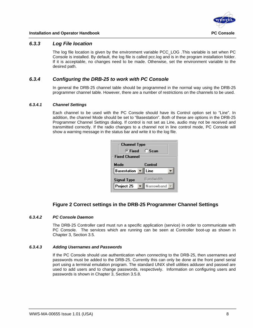
Installation and Operator Handbook PC Console
WWS-MA-00655 Issue 1.01 (USA) 8
6.3.3 Log File location The log file location is given by the environment variable PCC_LOG .This variable is set when PC Console is installed. By default, the log file is called pcc.log and is in the program installation folder. If it is acceptable, no changes need to be made. Otherwise, set the environment variable to the desired path.
6.3.4 Configuring the DRB-25 to work with PC Console In general the DRB-25 channel table should be programmed in the normal way using the DRB-25 programmer channel table. However, there are a number of restrictions on the channels to be used.
6.3.4.1 Channel Settings
Each channel to be used with the PC Console should have its Control option set to “Line”. In addition, the channel Mode should be set to “Basestation”. Both of these are options in the DRB-25 Programmer Channel Settings dialog. If control is not set as Line, audio may not be received and transmitted correctly. If the radio changes to a channel not in line control mode, PC Console will show a warning message in the status bar and write it to the log file.
Figure 2 Correct settings in the DRB-25 Programmer Channel Settings
6.3.4.2 PC Console Daemon
The DRB-25 Controller card must run a specific application (service) in order to communicate with PC Console. The services which are running can be seen at Controller boot-up as shown in Chapter 3, Section 3.5.
6.3.4.3 Adding Usernames and Passwords
If the PC Console should use authentication when connecting to the DRB-25, then usernames and passwords must be added to the DRB-25. Currently this can only be done at the front panel serial port using a terminal emulation program. The standard UNIX shell utilities adduser and passwd are used to add users and to change passwords, respectively. Information on configuring users and passwords is shown in Chapter 3, Section 3.5.8.
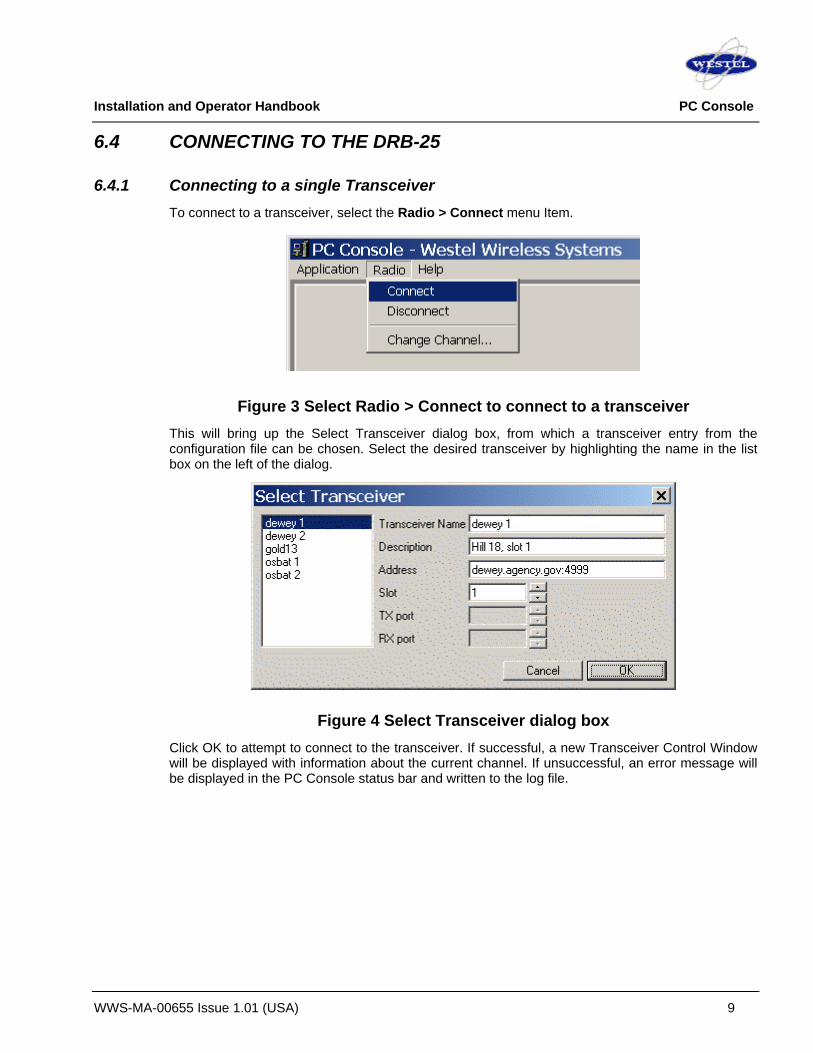
Installation and Operator Handbook PC Console
WWS-MA-00655 Issue 1.01 (USA) 9
6.4 CONNECTING TO THE DRB-25
6.4.1 Connecting to a single Transceiver To connect to a transceiver, select the Radio > Connect menu Item.
Figure 3 Select Radio > Connect to connect to a transceiver This will bring up the Select Transceiver dialog box, from which a transceiver entry from the configuration file can be chosen. Select the desired transceiver by highlighting the name in the list box on the left of the dialog.
Figure 4 Select Transceiver dialog box Click OK to attempt to connect to the transceiver. If successful, a new Transceiver Control Window will be displayed with information about the current channel. If unsuccessful, an error message will be displayed in the PC Console status bar and written to the log file.

Installation and Operator Handbook PC Console
WWS-MA-00655 Issue 1.01 (USA) 10
Figure 5 Transceiver Control Window
6.4.1.1 Logging In
If the DRB-25 is configured to require authentication, a username and password must be sent when connecting. This can be done in three ways:
1. Store the username and password in the configuration file;
2. Store the username only in the configuration file and enter the password when connecting;
3. Enter the username and password when connecting.
Use of the configuration file is discussed in Section 0. If the username and/or password must be entered when connecting, a dialog is shown:
Figure 6 User and Password dialog
6.4.1.2 Connecting to Multiple Transceivers
The procedure described above can be repeated to connect to multiple transceivers simultaneously.
6.4.2 Selecting Transceivers
6.4.2.1 Selecting a Transceiver
A transceiver is selected when the transceiver name field is blue with white text, and unselected when gray with black text. To select a transceiver, left-click on the transceiver name field. Any other transceivers will be deselected.

Installation and Operator Handbook PC Console
WWS-MA-00655 Issue 1.01 (USA) 11
Figure 7 Selecting Transceivers
Note that the lower Transceiver Control Window is selected, the upper one is not
6.4.2.2 Selecting Multiple Transceivers
More than one Transceiver can be selected simultaneously. This feature is used when transmitting with more than one Transceiver at once, for example. To select multiple transceivers, select the first with the left mouse button, then select the second in then same way while holding the SHIFT key. The Transceiver name field of both should then be highlighted (white text on blue background).
6.4.3 Disconnecting from a Transceiver 1. Select it by clicking in the Transceiver name field
2. Select the Disconnect menu item from the Radio Menu
Figure 8 Select Radio->Disconnect to disconnect from a Transceiver

Installation and Operator Handbook PC Console
WWS-MA-00655 Issue 1.01 (USA) 12
6.5 THE TRANSCEIVER CONTROL WINDOW
6.5.1 Main display fields This section describes the main fields in the Transceiver Control Window.
Figure 9 Transceiver Control Window fields Transceiver Name: The name assigned to the Transceiver in the PC Console configuration file. See Section 0.
Channel No.: The number of the current channel in the Transceiver’s channel table.
Channel Name: The name of the current channel in the Transceiver’s channel table, set using the DRB-25 Programmer application.
Radio Mode: The current operating mode of the Transceiver. This indicates both Analog/Project25/Autosense and Basestation/Repeater. Settings. For Analog modes, it also indicates the squelch type.
Mute Button: This is a toggle-style button. When in the “pressed” position, audio received from this Transceiver is not send to the soundcard. The audio level is still monitored on the RX audio level control.
Mute Indicator: This is read when RX audio is muted.
Connection Status: This displays the status of the TCP connection between the PC Console application and the DRB-25, based on heartbeat messages sent by the DRB-25. Normally it is green, but if the heartbeats do not arrive regularly it will change from green to orange and then to red.
TX audio level: The amplitude of audio being transmitted by the Transceiver.
RX audio level: The amplitude of audio being received by the Transceiver.
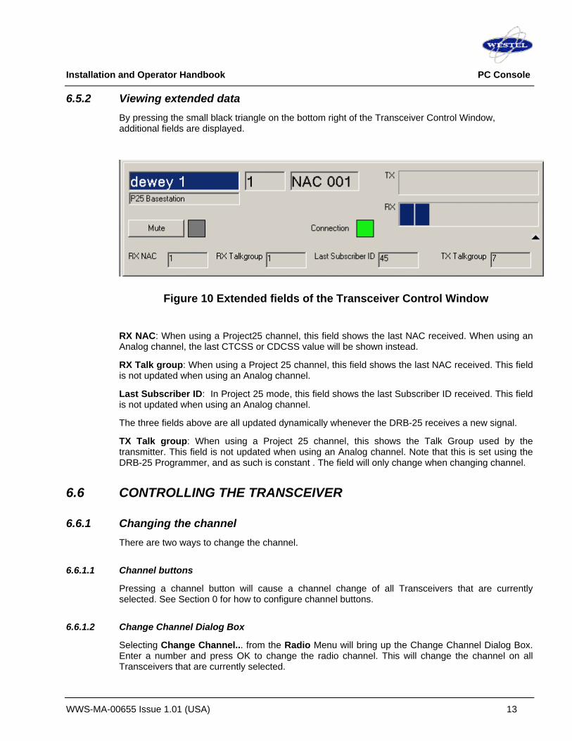
Installation and Operator Handbook PC Console
WWS-MA-00655 Issue 1.01 (USA) 13
6.5.2 Viewing extended data By pressing the small black triangle on the bottom right of the Transceiver Control Window, additional fields are displayed.
Figure 10 Extended fields of the Transceiver Control Window
RX NAC: When using a Project25 channel, this field shows the last NAC received. When using an Analog channel, the last CTCSS or CDCSS value will be shown instead.
RX Talk group: When using a Project 25 channel, this field shows the last NAC received. This field is not updated when using an Analog channel.
Last Subscriber ID: In Project 25 mode, this field shows the last Subscriber ID received. This field is not updated when using an Analog channel.
The three fields above are all updated dynamically whenever the DRB-25 receives a new signal.
TX Talk group: When using a Project 25 channel, this shows the Talk Group used by the transmitter. This field is not updated when using an Analog channel. Note that this is set using the DRB-25 Programmer, and as such is constant . The field will only change when changing channel.
6.6 CONTROLLING THE TRANSCEIVER
6.6.1 Changing the channel There are two ways to change the channel.
6.6.1.1 Channel buttons
Pressing a channel button will cause a channel change of all Transceivers that are currently selected. See Section 0 for how to configure channel buttons.
6.6.1.2 Change Channel Dialog Box
Selecting Change Channel... from the Radio Menu will bring up the Change Channel Dialog Box. Enter a number and press OK to change the radio channel. This will change the channel on all Transceivers that are currently selected.

Installation and Operator Handbook PC Console
WWS-MA-00655 Issue 1.01 (USA) 14
Figure 11 Change Channel menu item
Figure 12 Change Channel dialog box
Note that in both cases, the channel change will only succeed if the channel has been previously programmed using the DRB-25 Programmer application.
6.6.2 Receiving Audio Whenever squelch opens on the Transceiver, audio will be streamed across the IP network to the connected PC Console application. The received audio level will be indicated on the RX Audio Level indicator. The received audio will be automatically sent to the sound card for playback through speakers or headphones. The Mute button on each Transceiver Control Window can be used to listen to any combination of connected transceivers.
6.6.3 Transmitting Audio When the Transmit Button is activated, audio will be streamed across the IP network to the DRB-25 and transmitted over the air. The Transmit Button can be activated by pressing and holding with the mouse, or by clicking on the Transmit Bar and pressing the space key. Audio will be streamed to all transceivers that are currently selected.
Figure 13 The Transmit Bar

Installation and Operator Handbook PC Console
WWS-MA-00655 Issue 1.01 (USA) 15
The audio level meter on the Transmit Bar shows the audio level of the input to the PC Console application. When transmitting, the TX audio meter on selected Transceiver Control Windows will show the same level to indicate transmission.
6.7 TROUBLESHOOTING The most helpful tool when troubleshooting PC Console is the log file which by default is written to the installation directory. PC Console logs all its actions to this file, as well as warnings and errors.
Things that can go wrong:
6.6.1 Network connectivity Make sure there is basic IP network connectivity between the PC and the DRB-25. This can be done using the ping program.
6.6.2 Firewalls If there is a firewall between the PC and the DRB-25, this may prevent connecting to the DRB-25 or sending/communicating audio data. Check with your system administrator and ensure that port 4999 is open to enable the transfer of control information and the audio ports chosen (8000 – 8xxx) to enable the transfer of audio.
6.6.3 DRB-25 configuration Ensure that the channel table is set up correctly as described in Section 5.
6.6.4 Audio I/O Ensure that the audio settings are correct on the PC. The output should not be muted, and the input should be set to “Microphone”, not “Line” if using a headset microphone.
6.8 LICENSES PC Console is copyright 2003, 2004 Westel Wireless Systems, All Rights Reserved.
PC Console includes third party software components that are not copyrighted by Westel Wireless Systems. License terms and copyrights for these components can be found in the licenses directory in the program installation folder.

Installation and Operator Handbook PC Console
WWS-MA-00655 Issue 1.01 (USA) 16
This page left blank intentionally.

Installation and Operator Handbook Diagnostics Monitor
WWS-MA-00656 Issue 0.04 (USA) 1
TABLE OF CONTENTS
7 DIAGNOSTICS MONITOR ............................................................................................................................................ 3 7.1 OVERVIEW ................................................................................................................................................................. 3 7.2 GETTING STARTED.................................................................................................................................................... 3
7.2.1 System requirements ..................................................................................................................................... 3 7.2.2 Obtaining a Copy of the DRB-25 Diagnostic Monitor................................................................................ 3 7.2.3 Installing the DRB-25 Diagnostic Monitor Software .................................................................................. 3 7.2.4 Starting DRB-25 Diagnostic Monitor for the First Time............................................................................. 3 7.2.5 Connecting the DRB-25 Diagnostic Monitor to the Controller Module ................................................... 4 7.2.6 Getting Help..................................................................................................................................................... 4
7.3 RUNNING THE DRB-25 DIAGNOSTIC MONITOR ....................................................................................................... 5 7.3.1 Configuration ................................................................................................................................................... 5 7.3.2 Configure Communications ........................................................................................................................... 5 7.3.3 Configure Polling Interval .............................................................................................................................. 7 7.3.4 Status/Test....................................................................................................................................................... 8 7.3.5 Alarms .............................................................................................................................................................. 9 7.3.6 Test ................................................................................................................................................................. 10 7.3.7 Changing the Password............................................................................................................................... 13
LIST OF FIGURES Figure 7-1 DRB-25 Diagnostic Monitor Main Window ...........................................................4 Figure 7-2 Configure Comms Dialog Box ................................................................................6 Figure 7-3 Polling Interval Dialog Box ......................................................................................7 Figure 7-4 Radio 1 and Radio 2 Status Dialog Box................................................................9 Figure 7-5 Alarms Dialog Box ..................................................................................................10 Figure 7-6 Password Dialog Box.............................................................................................11 Figure 7-7 Test Radio Dialog Box ...........................................................................................12 Figure 7-8 Change Password Dialog Box..............................................................................13
LIST OF TABLES Table 7-1 System Requirements...............................................................................................3 Table 7-2 Communications Parameters...................................................................................7

Installation and Operator Handbook Diagnostics Monitor
WWS-MA-00656 Issue 0.04 (USA) 2
This page left blank intentionally.

Installation and Operator Handbook Diagnostics Monitor
WWS-MA-00656 Issue 0.04 (USA) 3
7 DIAGNOSTICS MONITOR
7.1 OVERVIEW
DRB-25 Diagnostics Monitor is a Windows™ based software application running on an IBM™ compatible PC connected to the front panel RS-232 port (RJ-11) on the Controller Module of the DRB-25. ZDM allows an operator to monitor the activity and status of both transceiver modules together with the alarm status of all DRB-25 modules.
DRB-25 Diagnostics Monitor operates only with non-IP Controller modules.
7.2 GETTING STARTED
7.2.1 System requirements
The minimum system requirements for operation of the DRB-25 Diagnostics Monitor software application are given in Table 7-1.
Table 7-1 System Requirements
Component Minimum Recommended Computer 80386 Intel Pentium at 100 MHz
Operating system Windows 3.1 Windows 95 or Windows NT
RAM 4 Mb 16 Mb
Hard disc free space 1.5 Mb 10 Mb
Display type Super VGA Super VGA
Display resolution 640 x 480 pixels 1024 x 768 pixels
7.2.2 Obtaining a Copy of the DRB-25 Diagnostic Monitor
The DRB-25 Diagnostic Monitor is is available as a download from the Westel website.
7.2.3 Installing the DRB-25 Diagnostic Monitor Software
To install the DRB-25 Diagnostic Monitor software application:
1. Double-click on the file “setup.exe”. For floppy disk distributions this will be a top-level file, for CDROMS it may be located in a subdirectory named “disk1”.
2. Follow the instructions given by the Setup dialog boxes.
If installation problems occur contact Westel.
7.2.4 Starting DRB-25 Diagnostic Monitor for the First Time
To start the DRB-25 Diagnostic Monitor, select the ZDM icon from the Start | Programs menu.

Installation and Operator Handbook Diagnostics Monitor
WWS-MA-00656 Issue 0.04 (USA) 4
The DRB-25 Diagnostic Monitor main window will appear as shown in Figure 7.1.
Figure 7-1 DRB-25 Diagnostic Monitor Main Window
7.2.5 Connecting the DRB-25 Diagnostic Monitor to the Controller Module
To connect to a Controller Module:
1. A DRB-25 Programming Cable (Westel Part number AMX-CB-02272) is required. Connect the PC communications port to be used to the DRB-25 Controller Module RJ-11 serial port connector using the cable.
2. The DRB-25 Diagnostic Monitor will attempt to automatically establish communications with the Controller Module. If this is successful the status dialog boxes will open automatically. If not the Configure Comms dialog box will be opened.
3. Using the procedure given in Section “Configuring Communications”, set the PC communications port used to connect to the DRB-25, and the PC communication parameters required for the Controller Module. The Controller Module default communications settings are 9600 baud, 8 data bits, 1 stop bit and no parity (8N1).
7.2.6 Getting Help
To get help on the Transceiver Module programmer, from the main menu activate the Help pull-down menu and select Contents, Search or Index as required.
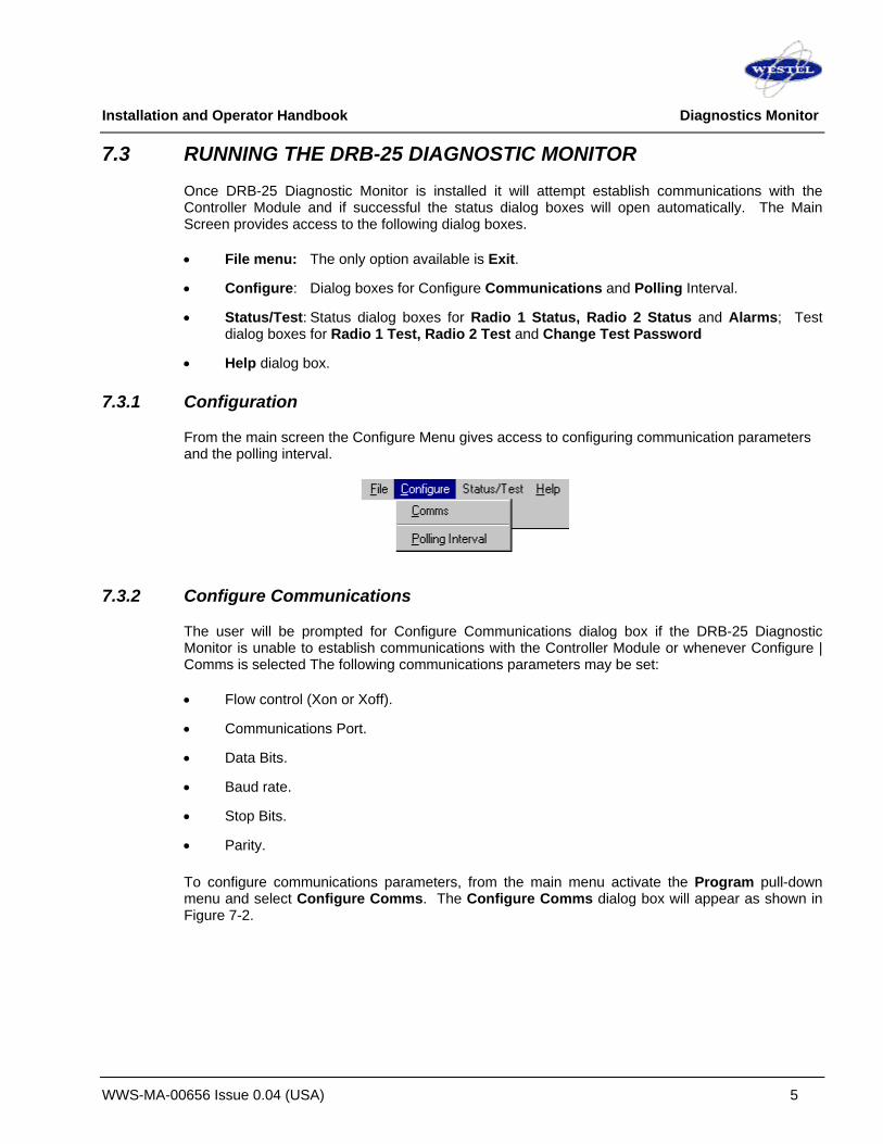
Installation and Operator Handbook Diagnostics Monitor
WWS-MA-00656 Issue 0.04 (USA) 5
7.3 RUNNING THE DRB-25 DIAGNOSTIC MONITOR
Once DRB-25 Diagnostic Monitor is installed it will attempt establish communications with the Controller Module and if successful the status dialog boxes will open automatically. The Main Screen provides access to the following dialog boxes.
• File menu: The only option available is Exit.
• Configure: Dialog boxes for Configure Communications and Polling Interval.
• Status/Test: Status dialog boxes for Radio 1 Status, Radio 2 Status and Alarms; Test dialog boxes for Radio 1 Test, Radio 2 Test and Change Test Password
• Help dialog box.
7.3.1 Configuration
From the main screen the Configure Menu gives access to configuring communication parameters and the polling interval.
7.3.2 Configure Communications
The user will be prompted for Configure Communications dialog box if the DRB-25 Diagnostic Monitor is unable to establish communications with the Controller Module or whenever Configure | Comms is selected The following communications parameters may be set:
• Flow control (Xon or Xoff).
• Communications Port.
• Data Bits.
• Baud rate.
• Stop Bits.
• Parity.
To configure communications parameters, from the main menu activate the Program pull-down menu and select Configure Comms. The Configure Comms dialog box will appear as shown in Figure 7-2.

Installation and Operator Handbook Diagnostics Monitor
WWS-MA-00656 Issue 0.04 (USA) 6
Figure 7-2 Configure Comms Dialog Box
The communications settings of the currently open file will be displayed. Where there is no file open, the default settings will be displayed. Table 7-2 lists the default communications settings.
To enter parameters:
1. Place the cursor on a cell where a change is required. The cursor will flash in the cell if placed there by use of the mouse. The cell will be highlighted if the Tab key is used.
2. Delete the existing value in the cell and enter the new parameter.
3. Click OK to update the current configuration.
OK
Closes the Configure Comms dialog box and writes any newly-entered communications data to the BP application’s .INI file.
Cancel
Closes the Configure Comms dialog box without writing data to the .INI file..
Help
Provides access to on-line help on the Configure Comms dialog box.
Table 7-2 lists the applicable ranges and defaults for the communications parameters.

Installation and Operator Handbook Diagnostics Monitor
WWS-MA-00656 Issue 0.04 (USA) 7
Table 7-2 Communications Parameters
Parameter Range/Description Default Flow Control Xon or Xoff X off
Baud Rate 1200, 2400, 4800, 9600, 14400, 19200 and 28800 9600
Com Port 1,2,3 etc. 1
Data Bits 7 to 10 8
Parity Odd, Even, None. O
Stop bits 1, 1.5, 2 1
7.3.3 Configure Polling Interval
The Configure | Polling Interval dialog box enables the user to set the interval at which the DRB-25 Diagnostic Monitor polls the Controller card for status information. The default polling interval is 1000ms. The Polling Interval Dialog box will appear as shown in Figure 7-3.
Figure 7-3 Polling Interval Dialog Box
To enter/change parameters:
1. Place the cursor in the cell
2. Delete the existing value in the cell and enter the new parameter.
3. Click OK to update the current configuration.
OK
Closes the Polling Interval dialog box and writes any newly-entered communications data to the ZDM application’s .INI file.
Cancel
Closes the Polling Interval dialog box without writing data to the .INI file..
Help
Provides access to on-line help on the Polling Interval dialog box.
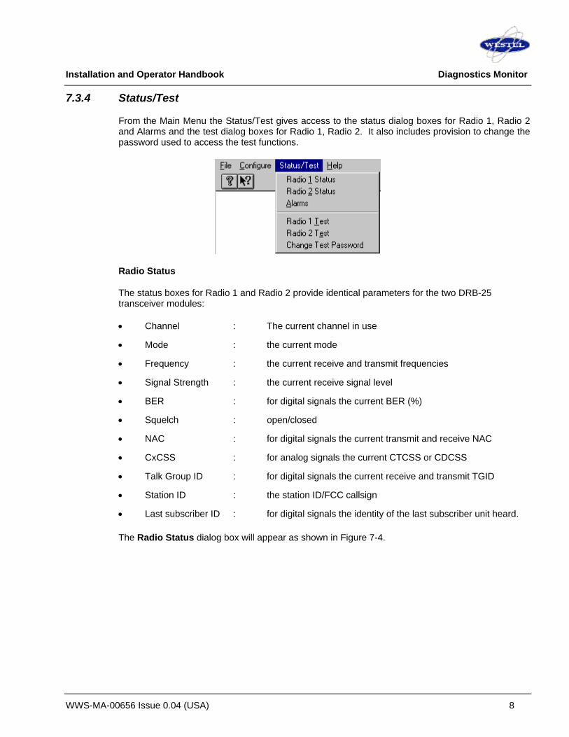
Installation and Operator Handbook Diagnostics Monitor
WWS-MA-00656 Issue 0.04 (USA) 8
7.3.4 Status/Test
From the Main Menu the Status/Test gives access to the status dialog boxes for Radio 1, Radio 2 and Alarms and the test dialog boxes for Radio 1, Radio 2. It also includes provision to change the password used to access the test functions.
Radio Status
The status boxes for Radio 1 and Radio 2 provide identical parameters for the two DRB-25 transceiver modules:
• Channel : The current channel in use
• Mode : the current mode
• Frequency : the current receive and transmit frequencies
• Signal Strength : the current receive signal level
• BER : for digital signals the current BER (%)
• Squelch : open/closed
• NAC : for digital signals the current transmit and receive NAC
• CxCSS : for analog signals the current CTCSS or CDCSS
• Talk Group ID : for digital signals the current receive and transmit TGID
• Station ID : the station ID/FCC callsign
• Last subscriber ID : for digital signals the identity of the last subscriber unit heard.
The Radio Status dialog box will appear as shown in Figure 7-4.

Installation and Operator Handbook Diagnostics Monitor
WWS-MA-00656 Issue 0.04 (USA) 9
Figure 7-4 Radio 1 and Radio 2 Status Dialog Box
The status parameters are updated at the rate specified in the Configure | Polling Interval dialog box.
Close
Closes the Radio Status dialog box.
Help
Provides access to On-line help for the Radio Status dialog box.
7.3.5 Alarms
The Alarms dialog box shows the status of the following DRB-25 parameters and alarms:
• VSWR hi/lo/normal
• Temperature critical/abnormal/normal
• Radio Fault Status on/off
• PA Fault on/off
• Controller Fault set/clear
• DC Standby on/off

Installation and Operator Handbook Diagnostics Monitor
WWS-MA-00656 Issue 0.04 (USA) 10
The Alarms dialog box will appear as shown in Figure 7-5.
Figure 7-5 Alarms Dialog Box
Close
Closes the Alarms dialog box.
Help
Provides access to on-line help on the Alarms dialog box.
7.3.6 Test
The Test dialog boxes (Test Radio 1 and Test Radio 2) enable the operator to select various APCO Project 25 digital and Analog FM test signals and conduct limited testing of the transmitter to verify the performance.
On entering the test dialog boxes the user will be prompted for a password. The Password dialog box will appear as shown in Figure 7-7.

Installation and Operator Handbook Diagnostics Monitor
WWS-MA-00656 Issue 0.04 (USA) 11
Figure 7-6 Password Dialog Box
Enter the Password corresponding to the Login for the module and click OK. Password entry is case-sensitive. Passwords are from 1 to 8 characters. The initial password is “ZDM”. For security, the password should be changed as soon as practical to a secret password known only to the user. Procedures for password change are in Section, 5.2.6 “Changing the Password”.
When the password has been successfully entered, the Transceiver Module programmer is now ready to read or write data to or from the DRB-25 module.
The following APCO Project 25 digital test signals are available:
• Standard 1011 Hz Test Tone;
• Standard Silence Test Pattern;
• Hi Deviation Pattern;
• Lo Deviation Pattern, and
• PRBS sequence.
The following Analog modulation test signals are available:
• 1000 Hz test tone, deviation = 1.5 kHz (25 kHz wideband FM)
• 1000 Hz test tone, deviation = 3.0 kHz (12.5 kHz narrowband FM)
The Test Dialog boxes allows the following radio controls to be exercised:
• Enable Local PTT (on/off) check box allows the user to transmit from a front panel microphone while the TDM is connected even if the channel in use has front panel PTT turned off.
• Enable Intercom check box shall allow the user to use a front panel microphone or handset to talk to a tone remote or console operator via 4 W/2 W interface while the TDM is connected.
• Select Channel.
The Test Radio dialog box will appear as shown in Figure 7-7.

Installation and Operator Handbook Diagnostics Monitor
WWS-MA-00656 Issue 0.04 (USA) 12
Figure 7-7 Test Radio Dialog Box
Apply
The Apply button sets the Enable Local PTT, Enable Intercom and Channel. This is, however, not stored on the Transceiver Module.
Tx On
The TDM Test dialog box Tx On button selection causes the TDM to write the factory test parameter to the selected Transceiver Module. The transmitter is turned on using the selected test tone as the modulation source. Note that if TDM is closed with TX On still selected then TDM will turn the transmitter off before closing and the transceiver will revert to its normal operating mode for its current channel.
Tx Off
Turns the transmitter off.
OK
Closes the Test dialog box returns the user to the Main dialog box. The transmitter is returned to the off state and the Enable Local PTT and Enable Intercom revert to their previous settings.
If a channel has been changed during a test session then a box will appear after the user closes the test dialog box : ‘The current channel of Radio x has been changed during this session. Do you wish to change the radio back to its original channel?’ Yes/No. If yes is clicked, then the channel will be changed back to the channel in use when the TDM session was started.
Cancel
Closes the Test dialog box without writing data to the .INI file..

Installation and Operator Handbook Diagnostics Monitor
WWS-MA-00656 Issue 0.04 (USA) 13
Help
Provides access to on-line help on the Polling Interval dialog box.
7.3.7 Changing the Password
To change the password, from the main menu activate the Status/Test pull-down menu and select Change Passwords. The Change Password dialog box will appear as shown in figure 7-8.
Figure 7-8 Change Password Dialog Box Enter the old password, followed by the desired new one. Enter the new password again in the bottom field for verification and click OK. The Tab key may be used to move between the text boxes.

Installation and Operator Handbook Diagnostics Monitor
WWS-MA-00656 Issue 0.04 (USA) 14
This page left blank intentionally.

Installation and Operators Handbook Appendix B
WWS–MA–00659 Issue 0.03 (USA) B-1
APPENDIX B MODULE ERROR CODES AND RECOMMENDED ACTIONS
1. VHF and UHF Transceiver
Error Description Recommended Action E01 – E04 Reserved E05 Channel Programming Error or
Empty Channel Table Check channel programming
E06 PA Comms Failure Check PA inserted correctly. If PSU fault light is on, or PSU power light is off, then replace PSU. Otherwise replace PA.
E07 PA Over Temperature Alarm Check fan operation E08 PA High VSWR Alarm Check antenna connections. E09 Remote Diagnostics Active An advisory, not an error. E10 PA Critical VSWR Alarm Check fan operation, requires reboot E11 PA Critical Temperature Alarm Check antenna connections, requires reboot E12 – E23 Reserved E24 DSP boot failure Replace Module
2. Non-IP Controller Error Description Recommended Action E01 – E22 Reserved E23 GPIO Xilinx boot failure Replace Controller Module E24 DSP boot failure Replace Module
3. IP Controller
The following error notifications may be displayed during boot-up of the IP Controller.
Error Description Error Description E01 Cannot read password or group file E13 Failed to load dsp driver E02 Reserved E14 Failed to start HDLC daemon E03 Failed to load xilinx driver E15 Failed to configure network interface E04 Failed to initialise glue xilinx E16 Failed to configure network routes E05 Failed to initialise GPIO xilinx E17 Failed to get network settings via DHCP E06 Failed to load SPI driver E18 Failed to start PC Console daemon E07 Failed to start webserver E19 Failed to start Interface Card daemon E08 Failed to load HDLC driver E20 Failed to start telnet daemon E09 Failed to load xc driver E21 Failed to load dsp program E10 Failed to load stbus driver E22 Failed to start DSP E11 Failed to activate xc E23 Failed to read configuration file E12 Failed to load Codec driver E24 Failed to set time via NTP
For further assistance in diagnosing errors contact Westel.

Installation and Operators Handbook Appendix B
WWS–MA–00659 Issue 0.03 (USA) B-2
This page left blank intentionally.

Installation and Operators Handbook Appendix C
WWS–MA–00670 Issue 0.01 (USA) C-1
APPENDIX C Additional Information This Appendix C provides additional information that may prove useful to users of the DRB-25. APPENDIX C Additional Information................................................................................................................................ 1 1. 4W INTERFACE MODULE (DISCONTINUED)........................................................................................................... 3
1.1 General Description................................................................................................................................................... 3 1.2 External Interfaces..................................................................................................................................................... 3
1.2.1 Radio Serial Data .............................................................................................................................................. 4 1.2.2 Analog Line Connection ................................................................................................................................... 5 1.2.3 Analog Line Jumper Settings ............................................................................................................................ 5 1.2.4 RS-485 serial data ............................................................................................................................................. 6 1.2.5 General Purpose Input/Output Lines ................................................................................................................. 6 1.2.6 External 10 MHz reference source .................................................................................................................... 7 1.2.7 Standby power................................................................................................................................................... 8 1.2.8 -48 V DC input.................................................................................................................................................. 8
2. MICROPHONE WIRING DIAGRAMS .......................................................................................................................... 9 2.1 CES Microphone Type 805....................................................................................................................................... 9 2.2 IDA Microphone Type V2000 ................................................................................................................................ 10
3. CABLE WIRING AND DIAGNOSTIC DATA............................................................................................................. 11 3.1 DC Revert Input Cable (WWS-CB-03002)............................................................................................................. 11 3.2 Programming Cable (WWS-CB-02272) ................................................................................................................. 11 3.3 GPS Data/Diagnostic Data Cable............................................................................................................................ 11 3.4. Diagnostic Data Output ........................................................................................................................................... 11

Installation and Operators Handbook Appendix C
WWS–MA–00670 Issue 0.01 (USA) C-2
This page left blank intentionally.
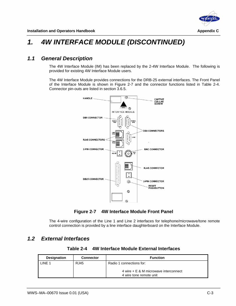
Installation and Operators Handbook Appendix C
WWS–MA–00670 Issue 0.01 (USA) C-3
1. 4W INTERFACE MODULE (DISCONTINUED)
1.1 General Description The 4W Interface Module (IM) has been replaced by the 2-4W Interface Module. The following is provided for existing 4W Interface Module users.
The 4W Interface Module provides connections for the DRB-25 external interfaces. The Front Panel of the Interface Module is shown in Figure 2-7 and the connector functions listed in Table 2-4. Connector pin-outs are listed in section 3.6.5.
Figure 2-7 4W Interface Module Front Panel
The 4-wire configuration of the Line 1 and Line 2 interfaces for telephone/microwave/tone remote control connection is provided by a line interface daughterboard on the Interface Module.
1.2 External Interfaces
Table 2-4 4W Interface Module External Interfaces
Designation Connector Function LINE 1 RJ45 Radio 1 connections for:
4 wire + E & M microwave interconnect 4 wire tone remote unit

Installation and Operators Handbook Appendix C
WWS–MA–00670 Issue 0.01 (USA) C-4
Designation Connector Function LINE 2 RJ45 Radio 2 connections for:
4 wire + E & M microwave interconnect 4 wire tone remote unit
SERIAL 1 DB9 Socket Radio 1 diagnostic data connection (RS-232) SERIAL 2 DB9 Socket Radio 2 diagnostic data connection (RS-232) LINK DB9 Plug RS485 serial data connection for APCO Project 25 Fixed
Station Interface (Ef) , digital console interface or multi-site voting (future options)
NET RJ45 Ethernet connection for VOIP and network management interface (future option)
I/O DB25 Socket General purpose input and output lines (6 inputs and 6 outputs), including dedicated outputs for antenna relay control and dedicated inputs for transmit disable
REF IN BNC External 10 MHz reference oscillator input STBY PWR 2-pin plug Standby power for reference oscillator oven. -48 V IN 2-pin plug DC input for E & M signaling
The general-purpose digital I/O provides six configurable inputs and outputs. Two of the output lines may be configured by jumper selection in the Interface Card to provide to drive 12 volt antenna relays for each of the transceivers. All other outputs, and these two when not configured as antenna drivers, provide optically-isolated contact closures which can be used to control other equipment.
The six inputs are also optically isolated. With an input of 5v to 10v they are sensed as active (on), when open circuited, they are sensed as inactive (off). The first two inputs are used to disable the transmitter during test.
The general purpose input and output lines, apart from the antenna relay outputs and transmit disable inputs, are unused in the present software release. In future releases user-configurability will be available.
1.2.1 Radio Serial Data Function: Radio Serial Diagnostic Data Located: Interface Module Label: Serial One, Serial Two (one per transceiver module) Electrical: RS-232 Connector: DB9 (female) Pin allocation:
Pin Function 1 Reserved 2 Receive data (input) 3 Transmit data (output) 4 Reserved 5 Ground 6 Reserved 7 Reserved

Installation and Operators Handbook Appendix C
WWS–MA–00670 Issue 0.01 (USA) C-5
Pin Function 8 Reserved 9 Reserved
1.2.2 Analog Line Connection Function: Provides line connections for PSTN, PBX, Microwave or tone remote control unit. Located: Interface Module Label: Line One and Line Two (one per transceiver module) Electrical: See table below Connector: RJ45 Pin allocation: (Pin 1 is the lower pin on the connector)
Pin Function (4 wire) 1 SB Lead 2 M lead 3 DRB-25 Receive Audio (+) - balanced signal, 600R,
0 dBm (nominal) 4 DRB-25 Transmit Audio (+) - balanced signal, 600R,
0 dBm (nominal) 5 DRB-25 Transmit Audio (-) - balanced signal, 600R,
0 dBm (nominal) 6 DRB-25 Receive Audio (-) - balanced signal, 600R,
0 dBm (nominal) 7 SG Lead (Gnd for external E/M supply) 8 E Lead
1.2.3 Analog Line Jumper Settings
The mode of operation of the E/M signaling is that when the radio squelch opens the M signaling line is connected to –48V DC active and when the E signaling line is asserted (by connection to –48V by an external equipment) the radio PTT function is asserted.
The Interface Module can support both Type I and Type II E/M signaling. Type I signaling uses an earth return, Type II signaling uses the SB line as the return for the M signaling line and the SG line as the return for the E signaling line.
The configuration of the E/M signaling interface to Type I or Type II is set using the links XL1 and XL2 as follows:
Line 1 Line 2 Type I (earth return)
XL1 : pin 2 - pin 3 XL2 : pin 2 - pin 3
Type II (SB and SG return)
XL1 : pin 1 – pin 2
XL2 : pin 1 – pin 2
4W phantom circuits are also supported by inserting solder links XLA1/2 and XLB1/2.

Installation and Operators Handbook Appendix C
WWS–MA–00670 Issue 0.01 (USA) C-6
Line 1 Line 2 E Line Signaling
Insert XLA1 Insert XLB1
M Line Signaling Insert XLA2
Insert XLB2
The default configuration of the 4 wire interface is as a console interface with pin allocation as shown in 3.6.5.5.2 above, suitable for connection to a tone remote console.
The interface may be reconfigured by jumper placement to an exchange interface suitable for connection to a PSTN or PABX network. The exchange configuration has pin 3 connected to DRB-25 Transmit Audio (-), pin 4 connected to DRB-25 Receive Audio (+), and is otherwise the same as the console configuration pin allocation.
To configure the pin allocation as either a console or exchange interface place the jumpers on connectors XL5, XL6 (line 1) and XL3, XL4 (line 2) as follows:
Line 1 Line 2 Connectors XL5 & XL6 XL3 & XL4 Console configuration jumper position (default) pin 1- pin 2 pin 1- pin 2 Exchange configuration jumper position pin 2- pin 3 pin 2- pin 3
1.2.4 RS-485 serial data Function: Currently unused. Located: Interface Module front panel Label: LINK Electrical: RS-485 Connector: DB9 (male) Pin allocation:
Pin Function 1 Reserved 2 Transmit data + (out of IAC) 3 Transmit data - (out of IAC) 4 Reserved 5 Ground 6 Reserved 7 Receive data + (into IAC) 8 Receive data - (into IAC) 9 Reserved
1.2.5 General Purpose Input/Output Lines Function: See descriptions below. Located: Interface Module Label: I/O Connector: DB25 (female)

Installation and Operators Handbook Appendix C
WWS–MA–00670 Issue 0.01 (USA) C-7
Function: Provides 6 general purpose inputs and outputs for control of transmit/receive antenna change-over relays, external site alarms and functions.
Pin allocation:
Pin Function 1 Antenna relay output radio 1: + 14 Antenna relay output radio 1: - 2 Antenna relay output radio 2: + 15 Antenna relay output radio 2: - 3 General purpose output 3: + 16 General purpose output 3: - 4 General purpose output 4: + 17 General purpose output 4: - 5 General purpose output 5: + 18 General purpose output 5: - 6 General purpose output 6: + 19 General purpose output 6: - 7 Transmit disable input radio 1: + 20 Transmit disable input radio 1: - 8 Transmit disable input radio 2: + 21 Transmit disable input radio 2: - 9 General purpose input 3: + 22 General purpose input 3: - 10 General purpose input 4: + 23 General purpose input 4: - 11 General purpose input 5: + 24 General purpose input 5: - 12 General purpose input 6: + 25 General purpose input 6: - 13 Ground
Transmit disable inputs:
When the + input is connected to +12 V and the - input to ground the relevant transmitter is disabled.
Antenna relay outputs:
Ensure that 4 links are present on Interface Module XM3. When the radio PTT is active, the + output is connected to +12V, the - output is connected to ground
1.2.6 External 10 MHz reference source Function: Provides 10 MHz input. When present automatically used in preference to
internal 10 MHz reference Located: Interface Module Label: REF IN

Installation and Operators Handbook Appendix C
WWS–MA–00670 Issue 0.01 (USA) C-8
Electrical: Level between 450 mV peak-peak and 4v peak-peak, impedance 50 Ohm Connector: BNC Pin allocation:
Pin Function Inner External reference input Outer Ground
1.2.7 Standby power Function: Maintain internal reference oscillator during power outages. Located: Interface Module Label: STDBY IN Electrical: 12 V DC (+/- 5%) input, max. current 1A Connector: 2 pin (male). Mating plug: Phoenix Contact MSTB 2.5/2-ST-5.08 Pin allocation:
Pin Function Upper +12 V DC ground (0 V) Lower +12 V DC input
1.2.8 -48 V DC input Function: Provides –48 V DC input for E/M signaling Located: Interface Module Label: -48 V DC Connector: 2 pin (male) Mating plug: Phoenix Contact MSTB 2.5/2-ST-5.08 Pin allocation:
Pin Function Upper -48 V DC ground (0 V) Lower -48 V DC input

Installation and Operators Handbook Appendix C
WWS–MA–00670 Issue 0.01 (USA) C-9
2. MICROPHONE WIRING DIAGRAMS
2.1 CES Microphone Type 805

Installation and Operators Handbook Appendix C
WWS–MA–00670 Issue 0.01 (USA) C-10
2.2 IDA Microphone Type V2000

Installation and Operators Handbook Appendix C
WWS–MA–00670 Issue 0.01 (USA) C-11
3. CABLE WIRING AND DIAGNOSTIC DATA
3.1 DC Revert Input Cable (WWS-CB-03002) The DC Revert Input Cable is terminated in a 4-pole Anderson Powerpole connector and provides separate DC feeds to Radio 1 and Radio 2. A cable assembly comprising a connector and 2 lengths of 65/0.3mm (4.6mm2) cable (approximately 1.5m long) is available by ordering Part Number WWS-CB-03002. Users wishing to make their own cable can obtain a copy of the cable assembly drawing from the ‘downloads’ area of the Westel Wireless web site www.westelwireless.com but are advised that fitting the Powerpole connector to the cable requires the use of a special crimping tool.
3.2 Programming Cable (WWS-CB-02272) The DRB-25 Programming cable is terminated at one end in an RJ11 plug and the other end in a DB9 (female). The cable (approximately 1.5m long) is available by ordering Part Number WWS-CB-02272.
3.3 GPS Data/Diagnostic Data Cable GPS and Diagnostic Data is available from the serial ports on the Interface Module. On the 2-4 Wire Interface Module these ports are provided on the DB25 (female) connector and a cable to connect the DB-25 to the serial ports on a PC or other equipment is available by ordering Part Number WWS-CB-02273. On the 4 Wire Interface Module (superseded) these ports are provided on individual DB9 (male) connectors labelled “Serial 1” and “Serial 2”. A cable to connect the DB-25 to the serial ports on a PC or other equipment and is available by ordering Part Number WWS-CB-02274.
3.4. Diagnostic Data Output To aid in troubleshooting DRB-25 operation both in analog and P25 digital modes, real-time diagnostic data from each transceiver is available from the Interface Module. To access the data connect a PC running a terminal emulator such as TeraTerm or Hyper-terminal to the DRB-25 using one of the cables described in section 3.3 above. The PC communications parameters for the serial interface should be set to 9600,8,N. The diagnostic data output is enabled in the Radio Wide settings of the DRB-25 programmer.

Installation and Operators Handbook Appendix C
WWS–MA–00670 Issue 0.01 (USA) C-12
The following is an example of diagnostic data output from DRB-25 operating in P25 digital repeater mode and using portables programmed with TGID = 1 and SUID = 2 and SUID = 3
Diagnostic Data Output Description Transceiver Version: 4.11 Event Log activated, with severity threshold -> Notice Using software flow control (XON/XOFF) SWInit: Digital Xilinx is OK. SWInit: Digital Xilinx (ID 0x10). SWInit: RF Xilinx OK (ID 0x02). SWInit: Box ID is 000. SWInit: Slot ID is 01. SWInit: Channel is ........ 000 SWInit: Receive ........... 157.625000 MHz SWInit: Transmit .......... 162.225000 MHz SWInit: Mode .............. Repeater SWInit: Signal type ....... Project25 C4FM SWInit: Rx NAC 0x293, Tx NAC 0x293 SWInit: Control ........... Tone-remote console SWInit: DSP downloaded OK. Used strict checking. SWInit: Tone Remote F1 .... Set channel to 0 SWInit: Tone Remote F2 .... Set channel to 1 SWInit: Tone Remote F4 .... Set channel to 4 SWInit: Tone Remote F5 .... Set channel to 5 SWInit: GX gain block set to 0 for codec channels 1 & 2. SWInit: Front Panel Vol ...100% SWInit: No changes on VSWR limits. State: Changing radio from OFFLINE (ch 0) to SIMPLE REPEATER (ch 0). Mode: Digital RPT Tne-Rme Biassing Exciter Stage... Exciter biassed OK State: Change done. DSPA stopped DSPB stopped DSPA restarted, Code version: 02.08 DSPB restarted
In this section the transceiver is booting up and its software version is shown. Various hardware items are initialized and firmware versions are shown. The Box ID is read The transceiver is in slot 1 The power up channel is 000 The characteristics of the channel are read from the channel table Control is set to Tone Control The Tone Remote characteristics are read from the channel table When everything is read the radio goes from its offline mode to its selected mode The Exciter stage is biased for the power output set in the channel table
[1] NAC 0x0293 DUID 0x0 RPT PTT: 80800000 [2] NAC 0x0293 DUID 0x5 RPT LC: LCO=0, P=0, SF=0, MFID=0, SID=2, TGID=1, SERVOPT=0 [3] NAC 0x0293 DUID 0xa RPT [4] NAC 0x0293 DUID 0x5 RPT LC: LCO=0, P=0, SF=0, MFID=0, SID=2, TGID=1, SERVOPT=0 [5] NAC 0x0293 DUID 0x3 RPT PTT: 00000000 [6] NAC 0x0293 DUID 0x0 RPT PTT: 80800000 [7] NAC 0x0293 DUID 0x5 RPT LC: LCO=0, P=0, SF=0, MFID=0, SID=3, TGID=1, SERVOPT=0 [8] NAC 0x0293 DUID 0xa RPT [9] NAC 0x0293 DUID 0x5 RPT LC: LCO=0, P=0, SF=0, MFID=0, SID=3, TGID=1, SERVOPT=0 [10] NAC 0x0293 DUID 0xa RPT [11] NAC 0x0293 DUID 0x3 RPT PTT: 00000000
This section shows a typical P25 repeated transmission NAC 293 is detected and PTT is set The received signal is from a subscriber unit with an SID of 2 and a Talk Group ID of 1 The received signal is lost & PTT is reset A NAC of 293 is detected and PTT is set The received signal is from a subscriber unit with an SID of 3 and a Talk Group ID of 1 The received signal disappears and the PTT is reset