DrawPlus 6.0 Companion
207
DrawPlus 6.0 Companion For Windows
Transcript of DrawPlus 6.0 Companion

DrawPlus 6.0 Companion For Windows

© 2001 Serif, Inc. All rights reserved.
The content of this publication is subject to change without notice and doesnot represent a commitment on the part of Serif, Inc. No part of thispublication may be reproduced in any form without the express writtenpermission of Serif, Inc.
All Serif product names are trademarks of Serif, Inc. Microsoft, Windows,and the Windows logo are registered trademarks of Microsoft Corporation.All other trademarks acknowledged.
Serif DrawPlus 6.0 © 2001 Serif, Inc.
Companies and names used in samples are fictitious.
Portions clipart and graphic content © 2000 Nova Development Corporationand its licensors. All rights reserved.
TrueType font samples from Serif FontPacks © Serif, Inc.
Portions graphics import/export technology © LEAD Technologies, Inc. &Eastman Kodak Company & INSO Corporation.
ImageStream® Graphics and Presentation Filters, Copyright © 1991-2000INSO Corporation. All Rights Reserved.

Software License AgreementThis Software License Agreement (“License Agreement”) is a legal agreement between you (either an individual or a single entity) and Serif,Inc. (“Serif”) for the accompanying software product, which includes computer software and may include associated media, printed materials,and “online” or electronic documentation (the “Software Product”). By installing, copying, or otherwise using the Software Product, you agreeto be bound by the terms of this License Agreement. If you do not agree to the terms and conditions of this License Agreement, do not install oruse the Software Product; you may, however, return it to your place of purchase for a full refund.
THANK YOU FOR LICENSING THE USE OF THE SOFTWARE PRODUCT. IT IS IMPORTANT THAT YOU (THE “LICENSEE”) READTHIS NOTICE CAREFULLY. THESE ARE THE ONLY TERMS AND CONDITIONS APPLICABLE TO YOUR RIGHTS WITH RESPECTTO THE SOFTWARE PRODUCT. THE SOFTWARE PRODUCT IS PROTECTED BY COPYRIGHT LAWS AND INTERNATIONALCOPYRIGHT TREATIES, AS WELL AS OTHER INTELLECTUAL PROPERTY LAWS AND TREATIES. THE SOFTWARE PRODUCTIS LICENSED, NOT SOLD.
1. GRANT OF LICENSESerif hereby grants to Licensee a personal, non-exclusive, non-transferable license (a “License”) to use one (1) copy of the SoftwareProduct, including any updates thereto, and accompanyingdocumentation, if any, provided by Serif, according to the terms setforth below. If the Software Product is being provided to Licensee asan update or upgrade to software which Licensee has previouslylicensed (such software referred to as the “Prior Software”), thenLicensee agrees to destroy all copies of the Prior Software withinthirty (30) days after opening this package except for one backupcopy of the Prior Software.
2. SCOPE OF USEYou may install and use one copy of the Software Product, on asingle computer. The primary user of the computer on which theSoftware Product is installed may make a second copy for his or herexclusive use on a portable computer. Licensee may also store orinstall a copy of the Software Product on a storage device, such as anetwork server, used only to install or run the Software Product onother computers over an internal network; however, you mustacquire and dedicate a license for each separate computer on whichthe Software Product is installed or run from the storage device. Alicense for the Software Product may not be shared or usedconcurrently on different computers.
3. LICENSE PAKIf you have acquired this LICENSE AGREEMENT in a SerifLicense Pak, you may make the number of additional copies of thecomputer software portion of the Software Product as authorized inthe Serif License Pak, and you may use each copy in the mannerspecified above. You are also entitled to make a correspondingnumber of secondary copies for portable computer use as specifiedabove.
4. PROHIBITIONSYou may not: modify, prepare derivative works from, translate,reverse engineer, decompile, disassemble or otherwise derive sourcecode from the Software Product (except to the extent that such actsare expressly permitted by applicable law notwithstanding thislimitation); copy the Software Product (except as provided above) orthe accompanying documentation; rent, transfer, disclose, makeavailable or grant any rights in the Software Product (including anyaccompanying documentation) in any form to any person without theprior written consent of Serif; remove any proprietary notices, labels,or marks on the Software Product (including any accompanyingdocumentation); use the Software Product in any manner thatinfringes the intellectual property or other rights of another party; oruse the Software Product to provide on-line or other databaseservices to any other person.
5. RETENTION OF RIGHTS; TERMINATIONThis License Agreement does not constitute a sale. All title, tradesecrets, copyrights, patents and other intellectual rights to theSoftware Product, its accompanying documentation and any copymade by Licensee remain with Serif, and Licensee hereby agrees topreserve and acknowledges the foregoing. Licensee further agrees
and acknowledges that the Software Product and all copies thereofare Serif’s exclusive property and constitute a valuable trade secretof Serif. Licensee further agrees and acknowledges that unauthorizedcopying of the Software Product or the accompanyingdocumentation, or failure to comply with any of the provisionshereof (each, a “Terminable Event”), will result in automatictermination of this License. In the event of a violation of this Licenseby Licensee, Serif reserves and shall have available all legalremedies.
6. TERM OF LICENSE FOR TRIAL VERSION SOFTWAREThe License pertaining to a trial version of the Software Product (a“Trial Version”) shall expire in accordance with the terms as setforth in the installation process for the Trial Version along with thedesignated trial period as set forth in the trial program.
7. LIMITED WARRANTY AND DISCLAIMERSerif warrants that, for a period of ninety (90) days after delivery, thediskettes or CD-ROMs on which the software included in theSoftware Product is furnished will, under normal use, be free fromdefects that prevent Licensee from loading the Software Product on acomputer. Serif’s entire liability and Licensee’s exclusive remedyunder this warranty will be, at Serif’s option, to (a) use reasonablecommercial efforts to attempt to correct or work around errors, or (b)to replace the Software Product with functionally equivalentSoftware Product, on diskettes or CD-ROM, as applicable or (c)return the price paid for the Software Product, in each case uponreturn of the Software Product to Serif together with a copy of yourreceipt for the purchase thereof. This Limited Warranty is void iffailure of the Software Product or hardware has resulted fromaccident, abuse, or misapplication. Any replacement SoftwareProduct will be warranted for the remainder of the original warrantyperiod or thirty (30) days, whichever is longer. Outside the UnitedStates, neither these remedies nor any product support servicesoffered by Serif are available without proof of purchase from anauthorized non-U.S. source. The Software Product is licensed to youon an “as is” basis without any warranty of any nature.
8. NO OTHER WARRANTIESExcept for the above express limited warranties, Serif and itssuppliers make and licensee receives no warranties or conditions, orterms, express, implied, statutory, or in any communication withlicensee. To the maximum extent permitted by applicable law, Serifand its suppliers disclaim all other warranties and conditions, eitherexpress or implied, including, but not limited to, implied warrantiesof merchantability, fitness for a particular purpose, title and non-infringement, with regard to the software product and the provisionof or failure to provide support services. Licensee shall be solelyresponsible for the selection, use, efficiency and suitability of thesoftware product and serif shall have no liability therefor. Serif shallhave no liability for, nor obligation to indemnify licensee regardingactions alleging the infringement of proprietary rights by thesoftware product. Serif does not warrant that the operation of thesoftware product will be uninterrupted or error free or that thesoftware product will meet licensee’s specific requirements. TheLimited Warranty gives you specific legal rights. You may haveothers, which vary from state/jurisdiction to state/jurisdiction.

9. LIMITATION OF LIABILITYIn no event will Serif or its suppliers be liable for loss of data,corruption, lost profits, cost of cover, or other special, incidental,punitive, consequential, or indirect damages arising from the use ofthe software product (including any accompanying documentation),however caused and on any theory of liability. This limitation willapply even if Serif or an authorized distributor has been advised ofthe possibility of such damage. In no event will Serif’s liabilityexceed the amount paid for the software product. Licenseeacknowledges that the amounts paid by licensee for the softwareproduct reflect this allocation of risk. Some states or otherjurisdictions do not allow the exclusion or limitation of liability forincidental or consequential damages, so the above limitations andexclusions may not be applicable in certain instances. None of theabove affects the statutory rights of licensees residing in the UnitedKingdom.
10. NOT FOR RESALE SOFTWAREIf the Software Product is labeled “Not for Resale” or “NFR,” then,notwithstanding section 1 of this License, your use of the SoftwareProduct is limited to use for demonstration, test, or evaluationpurposes.
11. NO RENTAL; OTHER TRANSFERSYou may transfer this License to another computer or workstationonly on a permanent basis (that is, with no intent to transfer again)provided the computer, workstation, or other digital electronicdevice from which you have transferred this License no longeraccesses or otherwise utilizes the Software Product, and the SoftwareProduct is used in accordance with the terms of this LicenseAgreement.
12. TERMINATIONYou may terminate this License Agreement at any time. Serif mayterminate this License Agreement if you fail to comply with theterms and conditions of this License Agreement. In either event, youmust destroy all copies of the Software Product.
13. UPGRADEIf this License is an “Upgrade,” you must have a valid license for thePrior Software for this License Agreement to be valid, and thisLicense Agreement must be used to replace such license for the PriorSoftware. The total number of license “Upgrades” you may acquiremay not exceed the total number of computers, workstations, orother digital electronic devices that were licensed to access orotherwise utilize the Software Product at the time you upgraded theSoftware Product.
14. GUIDELINES FOR THE USE OF DIGITAL CONTENTIMAGESThis product contains numerous clipart and photo images(collectively referred to as the “Images”) which are either owned bySERIF or licensed from a third party. As a user of this product youare free to use, modify, and publish the Images as you wish subjectto the restrictions set out below. If you are uncertain as to whetheryour intended use complies with the guidelines set out below, werecommend that you seek the advice of your own attorney or legalcounsel.
A. YOU MAY, subject to any restrictions set out below:
1. Incorporate any Image(s) into your own original work andpublish, display, and distribute your work in any media. You may
not, however, resell, sublicense, or otherwise make available theImage(s) for use or distribution separately or detached from aproduct or Web page. For example, the Image(s) may be used as partof a Web page design, but may not be made available fordownloading separately or in a format designed or intended forpermanent storage or reuse by others. Similarly, clients may beprovided with copies of the Image(s) (including digital files) as anintegral part of a work product, but may not be provided with theImage(s) or permitted to use the Image(s) separately or as part of anyother product;
2. Make one (1) copy of the Image(s) for backup or archivalpurposes.
B. YOU MAY NOT:
1. Create scandalous, obscene, defamatory, or immoral works usingthe Image(s) nor use the Image(s) for any other purpose prohibitedby law;
2. Use or permit the use of the Image(s) or any part thereof as atrademark or service mark, or claim any proprietary rights of anysort in the Image(s) or any part thereof;
3. Use the Image(s) in electronic format, on-line, or in multimediaapplications unless (a) the Image(s) are incorporated for viewingpurposes only and (b) no permission is given to download and/orsave the Image(s) for any reason;
4. Rent, lease, sublicense, or lend the Image(s), or a copy thereof, toanother person or legal entity. You may, however, transfer all yourlicense to use the Image(s) to another person or legal entity, providedthat (a) you transfer the Image(s) and this License, including allcopies (except copies incorporated into your work product aspermitted under this License), to such person or entity, (b) that youretain no copies, including copies stored on a computer or otherstorage device, and (c) the receiving party agrees to be bound by theterms and conditions of this License;
5. Use any Image(s) except as expressly permitted by this License.
15. MISCELLANEOUSa. This Agreement shall not be governed by the 1980 U. N.Convention on Contracts for the International Sale of Goods; rather,this Agreement shall be governed by the laws of the State of NewJersey, of the United States of America, including the UniformCommercial Code of the State of New Jersey, without reference toconflicts of law principles. This Agreement is the entire Agreementbetween Serif and Licensee and supersedes any othercommunications or advertising with respect to the Software Product.If any provision of this Agreement is held invalid or unenforceable,such provision shall be revised to the extent necessary to cure theinvalidity or non-enforceability, and the remainder of thisAgreement shall continue in full force and effect. If the SoftwareProduct is acquired by the United States Government or on itsbehalf, the Software is furnished with restricted rights. The use,duplication, or disclosure by the United States Government andparties acting on its behalf is governed by, and subject to restrictionsas set forth in subdivision (c) (1) (ii) of the Rights in Technical Dataand Computer Software clause at DFARS 252.227-7013, thesubparagraphs (c)(1) and (2) of the Commercial Computer Software- Restricted Rights at 48 CFR 52.227-19, or other comparableregulations of other government agencies, as applicable. Licenseeagrees not to allow the Software Product to be sent to or used in anyother country except in compliance with applicable United Stateslaws and regulations. This Agreement shall constitute the entireagreement between Serif and Licensee and supersedes all prioragreements, understandings, communications, proposals orrepresentations, oral or written, by either party. This Agreement shallbe amended only by an executed writing by authorizedrepresentatives of both parties.

How to contact us
Our main office (USA, Canada):The Software CenterPO Box 803, Nashua NH 03061 USA
Main (603) 889-8650Registration (800) 794-6876Sales (800) 55-SERIF or 557-3743Technical Support (603) 886-6642Customer Service (800) 489-6720General Fax (603) 889-1127
Technical Support E-mail [email protected]
European office (UK, Europe):The Software CentrePO Box 2000, Nottingham, NG11 7GW, UK
Main (0115) 914 2000Registration (0500) 454 645Sales (0800) 376 4848Technical Support (0115) 914 9090Customer Service (0115) 914 9090General Fax (0115) 914 2020
Technical Support E-mail [email protected]
OnlineVisit us on the Web at http://www.serif.com
InternationalPlease contact your local distributor/dealer. For further details please contactus at one of our phone numbers above.
Comments or other feedbackWe want to hear from you! E-Mail [email protected] with your ideas andcomments!

Contents
1 ♦♦♦♦ Welcome
Introduction...............................................................................................3About this book.........................................................................................3About DrawPlus 6.0 ..................................................................................4
What’s new in DrawPlus 6.0 .............................................................4Plus these established features... .....................................................6
Registration, Upgrades, and Support .......................................................9Installation ................................................................................................9
What you need to run DrawPlus .......................................................9What you need to know ..................................................................10First-time install...............................................................................10DrawPlus 6.0 Design CD-ROM.......................................................10Manual install/re-install ...................................................................10
2 ♦♦♦♦ Getting Started
Getting Started........................................................................................13DrawPlus Startup Wizard........................................................................13PROJECT: Birthday Card .......................................................................14Let’s Experiment .....................................................................................16Finish Up….............................................................................................18
Save your card................................................................................18Print your card.................................................................................18
Saving vs. Exporting ...............................................................................19Getting Help............................................................................................19
3 ♦♦♦♦ Wizards at Work
Introduction.............................................................................................23PROJECT: Creating a Bookplate ...........................................................23
Creating the document....................................................................23Setting guides .................................................................................24Using the Backdrop Wizard ............................................................25Resizing and repositioning..............................................................26Using Fill and Transparency ...........................................................28Using the Text Art Wizard ...............................................................29

Using the Border Wizard.................................................................30Using the Replicate Wizard.............................................................30Saving and printing .........................................................................31
4 ♦♦♦♦ Working with Objects
Introduction.............................................................................................35Types of Objects.....................................................................................35
Drawing basic lines and shapes .....................................................36Making a QuickShape.....................................................................38Typing text ......................................................................................39
Manipulating objects ...............................................................................40The selection tools ..........................................................................40Moving objects ................................................................................40Resizing objects..............................................................................41Rotating objects ..............................................................................42Shearing objects .............................................................................43Constraining a change ....................................................................43Deleting objects ..............................................................................44Changing your mind........................................................................44Cut, Copy and Paste.......................................................................44Quick copying .................................................................................45Right-click menus............................................................................45Adding more objects .......................................................................46Selecting overlapping objects .........................................................48Rearranging objects........................................................................48Selecting multiple objects ...............................................................49
Using the Portfolio ..................................................................................50What’s Next? ..........................................................................................51
5 ♦♦♦♦ Lines, Curves, and Shapes
Introduction.............................................................................................55Properties of lines and shapes........................................................55
Extending and Redrawing Lines .............................................................56Extending a line ..............................................................................56Redrawing a line .............................................................................57
Editing Curves ........................................................................................58Reshaping a curve ..........................................................................58Fine-tuning a curve .........................................................................61Adding and removing nodes ...........................................................63Closing, opening, and joining curves ..............................................63Cleaning curves ..............................................................................64
Converting to Curves ..............................................................................65

PROJECT: A Simple Map.......................................................................65Roughing it......................................................................................66Roads under construction ...............................................................66Road improvements........................................................................67House building ................................................................................68Tearing the roof off..........................................................................69
6 ♦♦♦♦ QuickShapes, Connectors, Text, and Pictures
Introduction.............................................................................................73QuickShapes ..........................................................................................73
Editing QuickShapes.......................................................................74Connectors .............................................................................................75Text.........................................................................................................80
Text properties ................................................................................80Editing text ......................................................................................82Special text effects..........................................................................83
Pictures...................................................................................................84Importing pictures ...........................................................................84
Photo Wizard ..........................................................................................85OLE Objects ...........................................................................................87
DrawPlus drawings as OLE objects ................................................88Exporting Drawings as Pictures..............................................................89PROJECT: Building a Business Card.....................................................89
Working to size ...............................................................................90A suitable background ....................................................................90Putting QuickShapes to work..........................................................91Adding text ......................................................................................92Using the design elsewhere............................................................93
7 ♦♦♦♦ Fill, Line, and Transparency Effects
Introduction.............................................................................................97Fill Settings .............................................................................................97
The Fill tab ......................................................................................97Types of fills ....................................................................................98Applying a fill...................................................................................99Adjusting an object’s fill tint...........................................................100Adjusting an object’s fill path.........................................................100Adjusting an object’s fill colors ......................................................102Working with Mesh fills .................................................................106Adding fills to a gallery ..................................................................107Setting the default fill.....................................................................108Changing gallery colors and fills ...................................................109

Using the Bitmap fill gallery...........................................................110Adding new solid colors ................................................................111All about color schemes................................................................111
Line Settings.........................................................................................114The Line tab and line properties ...................................................114Applying line properties.................................................................115Adjusting an object’s line tint and color .........................................116Setting the default line ..................................................................117Using Format Painter ....................................................................117
Transparency Effects............................................................................118Transparency: The “vanishing” fill .................................................118The Transparency tab...................................................................119Applying a transparency effect......................................................120Adjusting an object’s transparency ...............................................120Plasma and Bitmap transparencies ..............................................121Changing gallery transparencies...................................................122
Creative Tips.........................................................................................122Transparency effects ....................................................................124
8 ♦♦♦♦ Using Layout Tools
Introduction...........................................................................................127Toolbars and Tabs................................................................................127Positioning Aids ....................................................................................128
Rulers............................................................................................128Guide lines ....................................................................................130The snapping grid .........................................................................130Snapping.......................................................................................131
Measurement Units and Scale..............................................................132Dimension Lines ...................................................................................133
Adjusting dimension lines .............................................................135The Status Tab .....................................................................................135Aligning Objects....................................................................................136Grouping Objects..................................................................................137A Balloon Example ...............................................................................137Locking an Object’s Position.................................................................139Object Defaults .....................................................................................139Layers...................................................................................................140PROJECT: The Map Revisited .............................................................142
Adding a church ............................................................................142Layers for different purposes ........................................................143A compass point ...........................................................................144

9 ♦♦♦♦ Special Effects
Introduction...........................................................................................149Text Effects...........................................................................................149
Font choices..................................................................................149Arranging letters............................................................................150Text on a curve .............................................................................151
Shadows...............................................................................................153Filter Effects..........................................................................................154Envelopes.............................................................................................1553D Perspective .....................................................................................157Roughening ..........................................................................................157Blends...................................................................................................158Chain Lines...........................................................................................159Multiple Copies .....................................................................................161
The Transform Wizard ..................................................................161The Replicate Wizard....................................................................162Contouring ....................................................................................163
Combining Objects ...............................................................................164Studio Library Elements........................................................................167
10 ♦♦♦♦ Web Graphics
Introduction...........................................................................................171Animation Basics ..................................................................................171
PROJECT: Spinning a spiral.........................................................172Previewing the animation..............................................................174Saving the DrawPlus file ...............................................................174Exporting animations ....................................................................174More on Animation mode..............................................................175
QuickShape Animation .........................................................................176Fooling the Eye: Animation Techniques ...............................................177
Follow the bouncing ball ...............................................................178Timing is everything ......................................................................179Using the Frame Manager ............................................................180A better bounce.............................................................................182
Other Animation Techniques ................................................................183Text animation ..............................................................................183Background frames.......................................................................183Overlay frames..............................................................................184Using frame edges........................................................................185
Imagine... ..............................................................................................186DrawPlus Samples........................................................................186Perception effects .........................................................................187

Character animation......................................................................187Simulations ...................................................................................188Web resources..............................................................................189
Image Slicing ........................................................................................189PROJECT: Slicing a navbar..........................................................189Previewing and exporting image slices .........................................192
Image Maps..........................................................................................192JavaScript Rollovers .............................................................................194
PROJECT: Adding rollovers .........................................................194Optimizing Graphics .............................................................................197
Bitmaps.........................................................................................198Web file formats ............................................................................199Using the Export Optimizer ...........................................................200

Welcome

Welcome 3
IntroductionWelcome to DrawPlus 6.0 and the remarkable power of vector graphics—thecomplete drawing, graphics and illustration solution for your home, school,church, or growing business. DrawPlus 6.0 can “do it all” for you, withautomated Wizards—or let you do it all yourself, with total control over itsversatile drawing features.
Whether you’re meeting DrawPlus for the first time or have been with itthrough many versions, you’re sure to appreciate 6.0’s combination of highperformance, fair price, and ease of use. In fact, it makes so many things soeasy to do, you might just think about retiring that paint program you’ve beenusing!
About this bookRead this book to learn how to install, start and use DrawPlus 6.0, from thebasics to tips and tricks for advanced users. Here’s a brief chapter summary:
1 Welcome. How to install and start DrawPlus and an overview of keyfeatures.
2 Getting Started. A quick look around the DrawPlus workspace and anintroduction to using Design Wizards.
3 Wizards at Work. How to create a masterpiece using some of the built-in Wizards.
4 Working with Objects. A solid, hands-on overview to help you become“object-oriented.”
5 Lines, Curves and Shapes. An in-depth look at creating and editingfigures built up from line objects.
6 QuickShapes, Text, Connectors, and Pictures. How to create and editthese other essential DrawPlus objects.
7 Line, Fill, and Transparency Effects. Introduces the concepts and toolsyou’ll need to create spectacular results.
8 Using Layout Tools. A tour of basic and advanced control features thatcan help you work accurately and efficiently.
9 Special Effects. A survey of additional tools and Wizards to enhanceyour creativity, with plenty of design examples.

Welcome 4
10 Web Graphics. How to produce animations and hot JavaScripted slices,hotspots, and buttons for the World Wide Web.
NOTE: The Companion takes a hands-on approach—encouraging you tokeep DrawPlus open as you read and to experiment with tools and techniquesas you proceed. Whenever you see this “hand” symbol adjacent to aparagraph, it means an opportunity to try your hand at mastering anotherDrawPlus feature.
About DrawPlus 6.0From decorative page elements and logos to full-page illustrations, scaledrawings, and animated Web graphics—DrawPlus 6.0 does it all. With thepower of scalable vector graphics at your command, you’ll see the creativepossibilities open up right before your eyes! Whether you’re a beginner or anexpert, you'll find Wizards and tools you can use right away. With version6.0, DrawPlus has broken the price-performance barrier once again!
What’s new in DrawPlus 6.0
♦ Color SchemesWhether you’re starting with a Design Wizard or creating new designsfrom scratch, interchangeable color schemes let you recolor everythingin a flash! Simply tag objects with numbers... colors update instantlywhen the scheme changes.
♦ Perspective EffectsGet a new slant on things... With a flyout full of presets plus a built-intool for freeform adjustments, the 3D Perspective option lets you tilt andskew text (or any other object) for truly “spatial” results!
♦ Filter EffectsDrop shadows starting to wear a bit thin? Now you can enliven your textwith fully adjustable Inner Shadow, Glow, Bevel, and Emboss filters...easy to apply and sure to impress.
♦ CroppingNow any object can serve as a “cookie cutter” for trimming one or moreother objects into a single shape... and the effect is reversible so youwon’t lose your originals. Great for creating “reflections” of complexscenes!
�

Welcome 5
♦ Roughen ToolFor jagged, jaunty edges on text, lines, or QuickShapes, just drag the toolup or down for subtle or bold results.
♦ Shadow ToolBy popular demand, we’ve added an easy-access toolbar button that letsyou customize drop shadows... and (oh yes) beefed up the underlyingcode for faster, better shadow results.
♦ PortfolioLong a popular feature of Serif PagePlus, this addition to the DrawPlusStudio is sure to change the way you work. It’s a global repository forthe designs you use most often... just drag and drop to store an object,then reuse it in any DrawPlus document.
♦ Improved Line ControlNew Line tab properties provide an extra measure of flexibility forprecise results when resizing. Want to apply a gradient fill to a line? Noproblem—simply detach the line itself as a brand new object!
♦ Improved Fill ControlSkillfully applied, gradient fills can be the key to a fine illustration... andnow your skills can push new limits. With the nonlinear color contouradjustment, fine-tune how colors spread within the fill, for precise andperfect results.
♦ Autotrace Bitmaps to VectorEver wished you could work with paint-type art as points, lines, and fills(instead of pixels)? With our Autotrace converter, you can preview andadjust quality before import, then bring the item into DrawPlus in fullyeditable vector format.
♦ Download Time EstimatorPut away your calculator! For exporting Web graphics, where file sizeequals time (which equals money), we’ve included a handy drop-downthat instantly shows how much each of those graphics will cost you.
♦ And MoreHold the applause... Especially for returning users, it’s often these “littlethings” that make the difference. The multi-document interface lets youdrag and drop between DrawPlus windows. QuickShapes now havesettable line and fill defaults. The Layer Manager floats. Micro Nudgelets you adjust in teeny increments. The Pick Up Color button lets youchoose any color you can see on your screen. The Undo History listmakes backtracking easier. So let’s get on with it!

Welcome 6
Plus these established features...
♦ Great Display, Performance, and OutputWith anti-aliased screen display and smooth color blending, jaggies andbanding are a thing of the past. You’ll get superior printed results, withsmooth color blending. And DrawPlus supports Transparent GIF,Animated GIF, and PNG for forward-looking Web page design.
♦ Total Ease-of-UseDrawPlus makes powerful features available to anyone with a host ofease-of-use features designed to zap that learning curve. You’ll findaccelerated learning tools like ToolTips, context-sensitive Hints & Tipsand colorful QuickTours. The tabbed Studio—storing hundreds of presetlines, fills, transparencies, fonts, and design elements—is alwaysconvenient and ready to use. Especially for working at high zoom levels,the Navigator tab affords a thumbnail of your entire drawing with thevisible area shown as a draggable view box. And the Library tab addsscores of pre-built elements so you can take advantage of new tools andfeatures.
♦ QuickShapesCan’t draw? Won’t draw? QuickShapes are the answer! They work likeintelligent clipart… or the most powerful set of drawing tools you’veever envisaged. Even extremely complex shapes like spirals, petals, andwebs are simple to draw and customize using QuickShapes.
♦ Professional-Standard Drawing FeaturesFeatures like converting text to curves, defining custom envelopes, fullycustomizable drop shadows, layers, and scalable vector graphics givecomplete creative power. Plus special commands like Contour foroutlining and edge effects... Add to composite two shapes into one...Subtract for cropping and masking... Intersect to carve out unique shapesand regions.
♦ Advanced Fill SupportApply high-end conical, ellipse, 3-Color, 4-Color, Square, and Plasmafills to any text or shape for exciting, professional results. Simply dragsolid colors from the Studio’s Color tab onto a fill path to add or replacecolors for more subtle gradients. Use Bitmap fills—with over 200supplied bitmap images in a range of categories for textures andbackgrounds. Even import your own bitmaps and use them as fills onDrawPlus objects! Plus Mesh Fills for impressively varied gradientsusing a path-node network—easy to customize with the special toolbar.

Welcome 7
♦ Transparency EffectsTransparency can make the difference between flat, ordinary visuals andsparkling realism! And DrawPlus provides it all—a full range oftransparencies for shading, shadows, reflections, depth effects, and more.Achieve multi-level transparency effects just by dragging grayscaletones to set levels.
♦ Chain LinesHere’s the ultimate in decorative line effects: easy to apply from thescores of pre-supplied choices, just as easy to edit or create from scratch!Chains take drawn objects and link them in sequence along a designatedline, for marching footprints, themed borders—uniquely patterned,endlessly variable effects anywhere you want to apply them.
♦ Dimension Lines and Scale SettingClick a couple of times to take linear or angular measurements of anyobject on the page—DrawPlus displays the dimension using your choiceof ruler units, at your specified scale (say, one inch to two feet).Dimensions update when objects are moved or resized! Design roomlayouts, make maps, draw scale models... the choice is yours.
♦ ConnectorsFor drawing dynamic flow diagrams, schematics, family trees, and orgcharts, connector objects let you link your boxes and symbols and thenrearrange at will. Connection points stay put on each object... keepingconnections intact. Auto Connectors intelligently display bridges at linecrossings, and even route themselves around obstructive objects.
♦ Natural Curve EditingNo need to fumble with Bezier nodes... Simply click and drag to breakand redraw a curve at any point. Apply smoothing selectively tofreeform curves to eliminate that “shaky hand” appearance. Who saysyou can’t draw like a pro?
♦ Animation ModeTap the power of QuickShapes and Wizards to turn out Web animationsin no time—using advanced features like onion skinning, backgrounds,overlays, and frame management. Use the time you save to make moremovies!

Welcome 8
♦ Web Image Slices and Image MapsBeat the pros at their own game by using these techniques to add links toyour Web graphics! With a few clicks, divide images into segments —each with its own hyperlink and popup text—or add hotspots to specificregions. Of course, DrawPlus outputs all the necessary HTML code towrap the segments together.
♦ Rollover States for Web ButtonsTake image slicing even further—let DrawPlus create interactive Webgraphics that highlight or change state when users mouse over or click!Just create your variant graphics on the special layers, then export asusual.
♦ Web Browser PreviewOne click lets you see how your graphics will display in a Web browser,so you can quickly check quality, transparency, hyperlinks, and rolloverbehavior prior to final export.
♦ Backdrop and Watermark ElementsAdding abstract or themed backgrounds, for dazzling presentations orspace-styled scenes, is easy with Backdrop elements. And Watermarkelements make a notoriously difficult effect a snap to create with a widerange of customizable watermark designs on hand. Access both Wizardsvia the Studio’s Library tab.
♦ Border WizardVastly flexible Border Wizard instantly adds borders to the page or toindividual objects. Choose a border from the extensive library, or becreative and let Border Wizard guide you through building a uniquedesign.
♦ Image Export OptimizerThe Export Optimizer lets you see how your image will look (and howmuch space it will take up) before you save it! Its multi-window displayprovides side-by-side WYSIWYG previews of image quality at variousoutput settings, so you can make the best choice every time.
♦ Professional Print OutputNow your artwork can be prepared for professional printing straightfrom DrawPlus. Whether you’re creating color-separated PostScript®output or printing from your desktop, process color (CMYK) separationsfor full color printing will save money and time, every time.

Welcome 9
Registration, Upgrades, and SupportIf you see the Registration Wizard when you launch DrawPlus, please take amoment to complete the registration process. Just call Serif toll-free andprovide the installation number and code shown. We’ll give you apersonalized registration number in return. Remember, if you need technicalsupport please contact us. We aim to provide fast, friendly service andknowledgeable help.
Installation
What you need to run DrawPlusSerif DrawPlus 6.0 runs with Windows 95 or later, so you’ll need a PC setupthat runs Windows adequately. If you need help installing Windows orsetting up your printer, refer to Windows documentation and help.
♦ IBM compatible Pentium PC with CD-ROM drive and mouse (or otherMicrosoft compatible pointing device)
♦ Microsoft Windows® 95, 98, 98 SE, 2000, or Window NT®4.0 or lateroperating system
♦ 16MB (Windows 95/98), 24MB (Windows 98 SE), or 32MB (WindowsNT), or 64MB (Windows 2000) RAM
♦ 70MB (recommended install) free hard disk space
♦ VGA (256-color display) monitor or higher. For optimum display qualityand performance we strongly recommend that a “Hi-color” (16-bit) or“True color” (24/32-bit) display setting be used.
Additional disk resources and memory are required when editing large orcomplex documents.
Optional components include:
♦ Windows-compatible printer
♦ TWAIN-compatible scanner and/or digital camera
♦ Stylus or other input device
♦ Internet account and connection required for accessing online resources
Welcome 10
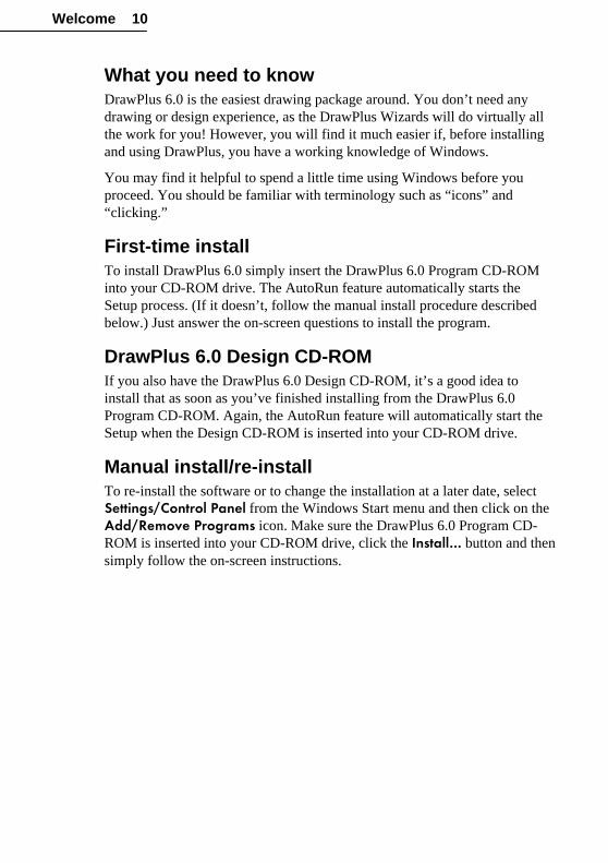
What you need to knowDrawPlus 6.0 is the easiest drawing package around. You don’t need anydrawing or design experience, as the DrawPlus Wizards will do virtually allthe work for you! However, you will find it much easier if, before installingand using DrawPlus, you have a working knowledge of Windows.
You may find it helpful to spend a little time using Windows before youproceed. You should be familiar with terminology such as “icons” and“clicking.”
First-time installTo install DrawPlus 6.0 simply insert the DrawPlus 6.0 Program CD-ROMinto your CD-ROM drive. The AutoRun feature automatically starts theSetup process. (If it doesn’t, follow the manual install procedure describedbelow.) Just answer the on-screen questions to install the program.
DrawPlus 6.0 Design CD-ROMIf you also have the DrawPlus 6.0 Design CD-ROM, it’s a good idea toinstall that as soon as you’ve finished installing from the DrawPlus 6.0Program CD-ROM. Again, the AutoRun feature will automatically start theSetup when the Design CD-ROM is inserted into your CD-ROM drive.
Manual install/re-installTo re-install the software or to change the installation at a later date, selectSettings/Control Panel from the Windows Start menu and then click on theAdd/Remove Programs icon. Make sure the DrawPlus 6.0 Program CD-ROM is inserted into your CD-ROM drive, click the Install… button and thensimply follow the on-screen instructions.

Getting Started

Getting Started 13
Getting StartedOnce DrawPlus has been installed you’re all ready to go! Setup adds aDrawPlus 6.0 icon to the Programs group of the Windows Start menu.
Click the Windows Start button to launch DrawPlus 6.0. If DrawPlus isalready running, choose New from the File menu.
DrawPlus Startup WizardThe Startup Wizard appears whenever you start DrawPlus and presents youwith seven choices.
The best way to get started learning about DrawPlus is to view the firstQuickTour, Introducing DrawPlus 6.0.
Click the fifth Startup Wizard choice, View a QuickTour.
�

Getting Started 14
When the QuickTour menu screen appears, click the Introducing DrawPlus 6.0 button. Once in the QuickTour, click the Next button to step forward, oruse the other control buttons to step back, redisplay the first screen, or returnto the menu.
To display the QuickTour menu later on, return via the Startup Wizard(choose File/New), or choose View a QuickTour from the Help menu.
Once you’ve viewed the introductory QuickTour, you’re ready for some realhands-on exploration! If you’re new to drawing software or want to makesure that you are getting the job done in the fastest and most economical way,then follow along in this Companion. You’ll find it’s an enjoyable journey,including tutorials, through the ideas that make DrawPlus easy and fun! Ifyou’ve used drawing software before, you may wish to skip ahead to sectionsof particular interest.
PROJECT: Birthday CardDrawPlus 6.0 has all the tools you need to draw anything from scratch, but italso offers plenty of instant ways to create drawings automatically. To seehow quick and easy it can be, let’s start by creating a personalized birthdaycard in just a few minutes.
Choose File/New to display the Startup Wizard again.
1 From the Startup Wizard’s menu screen, choose the first item, Use a
Design Wizard.
�

Getting Started 15
2 Click to expand the Greeting Cards category, then click the Birthday
subcategory. A list of thumbnail previews appears at the right.
3 Scroll down in the list and select “Cousin 01,” then click Next.
Now let’s use the Wizard to personalize the card.
4 Add the recipient’s name, your name, and the designer’s name (that’syou, too!) to the card by typing them in the boxes provided.
5 Click Finish to instruct the Wizard to create your greeting card.
If you change your mind, you can move back through the Wizard steps toreview any selection you’ve made, simply by clicking the Back button.
The Wizard takes just a few moments to do its work—and then you’ll seeyour drawing appear on the DrawPlus page!
Page Area
Pasteboard Area
HintLine
Studio

Getting Started 16
Take a moment now to review the key parts of the DrawPlus interface:
♦ The active area of the DrawPlus display is made up of two areas, thepage and the surrounding pasteboard area. You can draw onto eitherarea but it is the page area that will be printed. You can use thepasteboard to store items that you might want to use in a design or toexperiment with them. (The red lines through the middle are guidelinesplaced by the artist to aid in positioning.)
♦ DrawPlus tools are arranged in menus, toolbars, and the tabs containedin the Studio area on the right side of the screen.
♦ At the lower right you’ll see the HintLine readout. As you move themouse pointer over menu items, toolbar buttons, and tab controls, you’llsee popup ToolTips and capsule descriptions of each feature will appearin the HintLine.
Let’s ExperimentBefore printing the birthday card, we’ll use a few of the DrawPlus tools tomake some modifications to the drawing the Wizard produced.
First, we’ll introduce the Studio’s Scheme tab,which lets you experiment with different sets ofcomplementary colors. Click the Scheme tabnow—you’ll find it along with the other Studio tabson the right side—and a varied gallery of samplesappears. One of them is already selected: this is theone selected by the Wizard designer. Now it’s yourturn!
Click any of the other scheme samples and you’llsee the colors in the document change before youreyes. What’s the secret? Chapter 7 delves into theintricacies of color schemes, but they basicallywork like painting-by-numbers. Various objects in the Wizard documenthave been marked with numbers rather than with specific colors. Each timeyou select a new named scheme from the Studio gallery, the colors in thenew scheme map to their corresponding numbers. If you look closely, you’llsee that basic text in the document (for example, the cousin’s name) alwaystakes Scheme Color 1, the one shown in the first cell of each scheme sample.This happens to be black in the “Abacus” scheme, dark brown in “Apple,”and so on.
�

Getting Started 17
Moving right along, there’s a personalized graphic in the upper rightquadrant (the back of the card) that includes the designer’s name (yours, mostlikely) and we are going to reduce it slightly and reposition it. But first, let’srotate the whole assemblage so we can work right side up.
The entire drawing is a collection of objects. To select all the objects forrotation, choose Select All from the Edit menu. Then, click the Rotate 90ºbutton on the top toolbar. Click it again, and all the objects will have rotated180º, so the section we’ll be working on is now in the lower left.
Before you can make any changes to a single object, you have to select itindividually—for this, the Pointer tool was invented.
Click the Pointer tool button on the left toolbar (ifthe button is down, it’s already selected) and thensingle-click on the graphic of the person. You will seeeight square dots appear around it. These are theobject’s handles.
Now click the text just below the graphic. You’ll seehandles appear around the two lines of text as the selection switches; bothlines are part of the same text object.
To select both the text object and the graphic, holddown the Shift key and click the graphic again.Now the selection expands to include both objects.
Let’s take a closer look by zooming in on theselection. Click the Actual Size button on thebottom toolbar.
TIP: If you’re having trouble finding the ActualSize button on the toolbar, remember ToolTips.Move your mouse cursor over the buttons until youfind the one you want.
To resize, first position the cursor over one of the selection’s corner handles.The cursor changes and displays the size cursor. Click the handle and dragslightly in toward the center of the selection to reduce it. (If you accidentallydeselect one or both objects, just repeat the Shift-click procedure.)
Let’s reposition the selected objects a bit. Click in the middle of the selection(not on a handle), and drag it to the lower right corner of its quadrant.

Getting Started 18
Now for one more change. Click on the two-line text object to select it, andmake sure the graphic is deselected. Then, in the Studio on the right side ofthe screen, click the tab labeled Text, which will pop to the front revealingcontrols for setting font, style, and other text attributes.
Click the Italic button and you’ll see the object’s text respond bychanging style.
As you may have noticed (if you’re new to draw programs), everything inDrawPlus is an object that you can independently select and then vary. Bygrouping objects together you can create one object out of many, withincredible ease of manipulation each step of the way. It’s this infinitevariability that makes DrawPlus so powerful—you can try out as manydifferent local effects as you wish. You can always retrace your steps andyou don’t have to worry about damaging the graphic as a whole. And that’sonly the beginning!
Finish Up…Well, let’s call a halt to this mini-project and view the results!
Save your cardUse File/Save to save a copy of your edited card design. DrawPlus saves andopens files just like all your Windows applications.
Print your card1 Select File/Print….
2 Click the OK button.
If your card does not print properly, check your Windows documentation tomake sure that your printer is installed correctly.
When the page comes out of the printer, fold the card in half top to bottomand in half again left to right. (To go all the way, sign it and pop it in anenvelope!)

Getting Started 19
Saving vs. ExportingWhen you save a drawing, DrawPlus uses its own proprietary formats (.DPPfor drawings and .DPA for animations) to store the information. To be able toread the drawing into another application it has to be saved in one of themany standard formats. You can do this using the File/Export... command.For details on exporting, see online help (search on “exporting” in the Index)and also Chapter 10’s sections on “Exporting animations” and “OptimizingGraphics.”
Getting HelpAll the tools we have just used are explained more fully later in this book. Ifyou ever need help then it is always available: just choose Help Contentsfrom the Help menu or press F1.
Also, keep an eye out for the helpful hints that pop up automatically the firsttime you try certain operations. These contain useful information for any newuser.

Wizards at Work

Wizards at Work 23
IntroductionDesign Wizards are only one of several species of Wizard you’ll encounter inDrawPlus. There are tool Wizards that help automate processes likereplicating, transforming, and creating borders. In addition, the Studio’sLibrary tab is a veritable gold mine of elements you can use like “spareparts” to assemble a drawing. There’s still plenty of room for your owncreativity—in fact, by using Wizards you’ll save time on the repetitive tasks,leaving more time for the fun stuff!
PROJECT: Creating a BookplateThat’s right: an old-fashioned, high-tech bookplate, in this case oneespecially designed for kids. You can flip ahead through the chapter to seehow it’s going to turn out. We’ll actually produce a sheet of four bookplatesthat you can print, cut apart, and give to a youngster or perhaps use yourself.(You’ll have to supply your own glue!)
This mini-project will give you a chance to see several Wizards in action, andto build some confidence working with draw objects. If you’re new to theconcept of a draw program, you’ll find it’s a refreshing departure from labor-intensive paint programs. Here’s a brief tour guide to the steps we’ll follow:
♦ Creating a new document from scratch and placing guide lines
♦ Using a Wizard to create a backdrop for the bookplate design
♦ Selecting, resizing, and repositioning objects to improve the design
♦ Creating some simple shapes and applying fill and transparency
♦ Using a Wizard to introduce some text
♦ Using a Wizard to create a colorful border
Creating the documentWe’ll want to begin with a blank slate, so...
1 Start DrawPlus (or choose File/New if it’s already running).
2 Select Create a Drawing from the Startup Wizard.
�

Wizards at Work 24
3 Select a standard paper size such as Letter or A4. Check thatOrientation is set to Tall, then click Finish.
Setting guidesSince we’re going to produce four bookplates on one sheet of paper, we’llbegin by dividing the page area into four quadrants. We’ll create thebookplate design in one quadrant, and replicate the completed design to theempty quadrants.
The page margins are indicated by the magenta rectangle around your pagearea. We need to locate the halfway point along each margin.
1 Click the button where the two rulers intersect (at the upper left of theworkspace), and drag until it touches the upper left page margin corner,as in the illustration below. With the zero point now at the margincorner, you can quickly figure the midpoint along each side.

Wizards at Work 25
2 At the halfway point along the top margin (you don’t have to beabsolutely precise), click once on the ruler. The illustration shows whatthe cursor will look like. A vertical red guide line will appear. Also clickfor a guide line at the midpoint of the left edge. If necessary, you candrag the guide lines around after you’ve created them, or delete extraones by dragging and dropping them outside the workspace.
3 Double-click the ruler intersection and therulers will return to their original position.
Now you should have two “crosshairs” thatmeet in the middle of your page, nicelydividing it into quadrants. Don’t worry, theguide lines won’t show up when you outputyour drawing—their only function is to helpyou position elements.
Using the Backdrop WizardNext we’ll use the Library tab to assemble a backdrop for the bookplatedesign.
1 In the Studio area to the right of the workspace, click the Library tab tobring it to the front. Click the drop-down list and select the Backdrops
category, revealing a gallery of thumbnails from which to choose.
2 Drag the “Dinosaur 01” thumbnail onto your page.
3 The Wizard materializes to present you with some design choices. Pickthe same ones we did, clicking Next aftereach selection: Blueish sky (at the lowerleft); a Pterodactyl (at the upper right) to goin the sky; and a Mammoth (lower left, withtusks) for the foreground. On the last screen,click Finish.
In a moment, the backdrop appears, filling mostof the page area.

Wizards at Work 26
If you look closely to the lower left of the workspace, you’ll notice that anew tab labeled “Paper” has appeared alongside the tab labeled “Layer 1,”which was there before (take our word for it).
That’s because the Wizard has placed the backdrop on a separate documentlayer that sits behind the rest of the document. It’s called “Paper” because it’stheoretically where a piece of paper would be. Layers keep clusters of objectsseparate. The assumption is that once you’ve got a backdrop, you don’t wantit to get tangled up with other objects you create.
Resizing and repositioningAs created, the backdrop is far too big: we want it to occupy one quadrant,not the entire page. And we can improve its composition, for bookplatepurposes. No problem!
1 Click the Paper tab so you can work directly on the backdrop layer.
2 Using the Pointer tool (all our manipulations will be done with thistool), click once on the backdrop itself.
You’ll see the object’s eight handles appear—notice that it’s all one object atthis point—but also notice the special cursor icon that signifies the backdropis “locked” and cannot be moved. Locking the object is a safety measure thedesigner applied to prevent accidental changes. To move or resize it, we’llhave to unlock it first.
3 Choose Unlock Position from the Arrange menu. Now you’ll see anormal cursor and black handles.
4 Click in the middle of the object and drag it so its upper left corner fitsinto the upper left corner of the page area.
5 Drag the middle-bottom and middle-righthandles to resize the image a bit, so italmost reaches the guide lines marking theedges of the quadrant. Leave about aquarter of an inch white space on theseedges; we don’t want the object to be toobig.

Wizards at Work 27
6 Let’s zoom in on the object, now that it’s smaller. Click the Zoom
In button on the bottom toolbar once. Notice that the zoom percentage isshown. You can adjust your view by using the scrollbars at the right andbottom of the workspace.
Now for an Important Lesson about draw objects.
7 Right-click on the backdrop object and notice that the item “Ungroup” isenabled. This tells you that the object you’ve selected is a group—andthat you can ungroup it into its component parts. So go ahead and chooseUngroup.
While the selection appears not to have changed, it’s in fact no longer agroup, but now a multiple selection that includes all the components of thegroup—as one more click will show. The next series of actions willinterchange the positions and sizes of the two animals on the ground.
8 Click on the Mammoth and you’ll see it’s selected. Now click theFlip Horizontal button on the upper toolbar so the Mammoth faces tothe right. Click any of its corner handles and drag inwards to scale itdown until it’s slightly smaller than the blue fellow in the distance.Finally, drag the Mammoth off the backdrop and place it temporarily toone side.
9 Now it’s the blue Dinosaur’s turn. Click it and again choose FlipHorizontal. This time, drag outwards to scale it larger, and reposition itin the lower right corner.
10 Drag the Mammoth over to wheredinosaur used to be and adjust thesize and position of both objects tomatch the illustration.
The whole idea has been to open upsome space at the lower left—and thedinosaur’s gesture works better in theforeground anyway.

Wizards at Work 28
Using Fill and TransparencyWe’re done with the backdrop layer now, and ready to add a few simpleobjects to complete the bookplate.
1 Click the Layer 1 tab so you’re working on the layer above thebackdrop.
First we’ll use the QuickShape tool to draw a black rectangle as show in theillustration below (left).
2 Click the QuickShape button on the left toolbar and select theQuickBox button (at the upper left, the default shape) from the flyout.Click where you want one corner of the box to go, and drag to theopposite corner. When you release the mouse button, the box fills withthe default fill, almost certainly black at this point. Then you can clickthe box handles to resize or move it as needed. No doubt about it,QuickShapes are cool!
The next step is to set a different fill and apply a transparency effect to thepanel you’ve just drawn. Make sure the box is selected.
3 In the Studio, click the Color tab to bring it to the front. We want tochange the object’s solid fill to a lighter color, so find a light-coloredthumbnail further down in the gallery and click it to apply a different fill.We chose a pale purple shade (RGB 255, 218, 255 to be precise), butany fairly light tone will do.

Wizards at Work 29
4 Now click the Studio’s Transparency tab. You’ll see that thetransparency type is “None,” meaning it’s opaque at present. Click Solid
instead in the drop-down list, and drag the Level slider (just below thelist) to the right until it’s set at around 40%. As you drag, you’ll see thebackdrop beginning to emerge through the now-transparent panel.
Using the Text Art WizardOur backdrop came from the Library tab, you’ll recall, and we’ll return therefor another component.
1 Click the Library tab, then select the category Text Art. Select thesubcategory Effects and drag the “Effects 08” the thumbnail on to thebottom of the page.
2 In the Wizard, enter this text: “This book belongs to:”. Be sure to includethe final colon! Click Next, then Finish.
3 You’ll see the effect appear on the page where you dragged. Resize andposition the text effect to look like the example below by using thepointer tool.
Before drawing a white box under the text, recall that the default fill is stillblack. But we want a white box! The solution is to set the default fill to whitebefore drawing the box. Here’s how...
4 Deselect all the objects in the drawing by clicking somewhere wherethere are no objects—a blank region of the page. Then select the Colortab and click the plain white thumbnail at the top of the gallery. You’vejust reset the default fill.
5 Double-click the QuickShape button to choose the QuickBox tool again,and drag out a white box shape just below the text.

Wizards at Work 30
Using the Border WizardFor a finishing touch, we’ll use yet another Wizard to apply a colorful borderaround the name panel.
1 Click the transparent box behind the text to select it.
2 Click the Border Wizard
button on the left toolbar. Again,step through the Wizard screensmaking your choices. Choose aborder “from library” (clickNext) and “around currentselection” (click Next again). Inthe list of border styles, choosethe one named “Danger!” andspecify “0.10in” as the width.Click Finish.
...and the bookplate design is complete!
Using the Replicate WizardAll that’s left to do is take our one design, which (with some forethought) wefit into one quarter of the page, and duplicate it to the other three quadrants.The Replicate Wizard handles this nicely (and it’s great for label sheets, aswell).
In order to replicate the design, we need to be able to select all its elements.This is simply a matter of changing one setting.
1 Right-click either layer tab and check the item Edit All Layers. Now,instead of working with the layers one at a time, we can select anyobject—or all of them.
2 Choose Select All from the Edit menu. Now we have a multipleselection consisting of all the objects on the page. (If by chance youcreated any extra objects on the side, hold down the Shift key and clickeach one in turn to remove it from the selection. Only our bookplatedesign should be selected.)
3 Choose Replicate Wizard from the Tools menu. On the first screen,select “Position the objects for me”; on the second, choose 3 copies;click Next and then Finish.

Wizards at Work 31
The Wizard ponders for awhile and then distributes the three new copies soas to complete a 2 x 2 grid:
Saving and printingWith the Wizards’ help, you’ve completed the project! The bookplate sheet isready to go.
1 Click the Save button on the top toolbar and save your drawing.
2 To print, click the Print button (also on the top toolbar).

Working with Objects

Working with Objects 35
IntroductionA DrawPlus 6.0 drawing is made up of objects that can be picked up, movedand changed in many ways. If you were working with pencil and paper youwould have to erase and redraw a shape to move it a little to the right. UsingDrawPlus you can do the same job more directly and with far less work bypicking the shape up and moving it to where you want it to be! If you want tothink of a DrawPlus drawing in real-world terms, think of cut-out papershapes with low-tack adhesive; not pencil and paper.
The Design Wizards and Studio Wizards that we’ve explored so far can bethought of as “object factories.” They let you pick a design and leave youwith one or more new objects on the page. If the design is exactly what youwant then all that is left is for you to print it or export it. If you want topersonalize the design or add to it then you need to know how to work withobjects! Ready to go?
Types of ObjectsDrawPlus can create three basic types of objects:
♦ Basic lines and shapes are created with the three tools on the Drawingtoolbar’s Line Tool flyout. They all consist of one or more linesegments drawn between junction points called nodes. A straight lineand a curve are basically lines with different kinds of nodes at each end.A shape is a line whose ends have been connected to form an enclosedregion. We’ll cover the fine points in Chapter 5, “Lines, Curves, andShapes.”
♦ QuickShapes are pre-designed objects that you can instantly add to yourpage, then adjust and vary using control handles. To create aQuickShape, you choose one from the QuickShape flyout on theDrawing toolbar, which contains a wide variety of commonly usedshapes, including boxes, ovals, arrows, polygons and stars.
♦ Text objects are created by typing on the page after you’ve chosen theText tool on the Drawing toolbar. You can choose any font or size, andapply standard text formatting. There’s also a special dialog for editingtext on the page. Chapter 6, “QuickShapes, Connectors, Text, andPictures,” covers these in detail.

Working with Objects 36
To get our feet wet, let’s try creating using each of the creation tools toproduce some sample objects.
Drawing basic lines and shapesDrawPlus offers a choice of three line tools on its Line Tools flyout. None is“superior” to the others—each has its role to play. We’ll try them all, startingwith the simplest.
Locate the Line Tools flyout—it’s the fourth button down on the Drawingtoolbar at the left of the screen. It will be showing one of the three iconsbelow (the icon will change each time you choose a different line tool, toshow the last one you selected.)
Click the button and the flyout appears, with an icon foreach of the three tools.
Click the Straight Line Tool button in the middle. To draw a line,simply click with the left mouse button somewhere on the page and drag toanother point while holding down the mouse button, then release the mousebutton. Notice that the first click “anchors” one end of the line, and then youcan take your time moving the cursor around until the line is exactly whereyou want it. (But don’t worry if it turns out wrong—with DrawPlus you canalways go back and change it later!) Also notice the line’s two nodes, one ateach end.
Now return to the Line Tools button (which is now displaying theStraight Line tool’s icon), click it, and this time choose the left icon from theflyout, for the Freehand tool. Immediately, you’ll notice the Curve toolbarpop up. (This is used for editing drawn curves, and we’ll deal with itextensively in the next chapter.) Now pretend you’re a 4-year-old and justscribble a bit on the page by clicking once, then dragging randomly. Whenyou release the mouse button, your scribble turns into a complex curve,complete with square dots indicating its nodes—at the two ends, and at eachpoint where two line segments come together.
�
Working with Objects 37
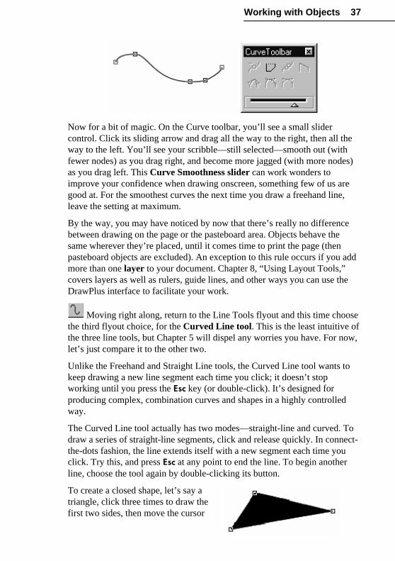
Now for a bit of magic. On the Curve toolbar, you’ll see a small slidercontrol. Click its sliding arrow and drag all the way to the right, then all theway to the left. You’ll see your scribble—still selected—smooth out (withfewer nodes) as you drag right, and become more jagged (with more nodes)as you drag left. This Curve Smoothness slider can work wonders toimprove your confidence when drawing onscreen, something few of us aregood at. For the smoothest curves the next time you draw a freehand line,leave the setting at maximum.
By the way, you may have noticed by now that there’s really no differencebetween drawing on the page or the pasteboard area. Objects behave thesame wherever they’re placed, until it comes time to print the page (thenpasteboard objects are excluded). An exception to this rule occurs if you addmore than one layer to your document. Chapter 8, “Using Layout Tools,”covers layers as well as rulers, guide lines, and other ways you can use theDrawPlus interface to facilitate your work.
Moving right along, return to the Line Tools flyout and this time choosethe third flyout choice, for the Curved Line tool. This is the least intuitive ofthe three line tools, but Chapter 5 will dispel any worries you have. For now,let’s just compare it to the other two.
Unlike the Freehand and Straight Line tools, the Curved Line tool wants tokeep drawing a new line segment each time you click; it doesn’t stopworking until you press the Esc key (or double-click). It’s designed forproducing complex, combination curves and shapes in a highly controlledway.
The Curved Line tool actually has two modes—straight-line and curved. Todraw a series of straight-line segments, click and release quickly. In connect-the-dots fashion, the line extends itself with a new segment each time youclick. Try this, and press Esc at any point to end the line. To begin anotherline, choose the tool again by double-clicking its button.
To create a closed shape, let’s say atriangle, click three times to draw thefirst two sides, then move the cursor

Working with Objects 38
over the line’s starting node. When you see the cursor change to include asmall box, click again. Instantly a shape object appears, filled with a defaultsolid black color. Remember, shapes are just lines that are closed uponthemselves.
To draw a complex curve, click and hold down the mouse button instead ofreleasing quickly. An additional pair of handles appear, defining a pair of redattractor nodes that orbit the original click point as you continue to drag themouse. What these nodes do is define the curvature of the line segmentyou’re about to draw—even though you haven’t drawn it yet!
Release the mouse button with the attractor nodes about a half-inch from thestarting node. Now click and hold again, a couple of inches away. The line’sfirst segment appears, and its curvature will respond as you drag out the newpair of nodes orbiting the second click point. Actually the node you’redragging feels like it’s “repelling,” since the segment curves away from it,while the opposite node does the actual “attracting.”
In Chapter 5, we’ll explore how to edit all these lines with the Node tool.Feel free to keep experimenting with the Curved Line tool at this point—andpick up the tour when you’re ready.
Making a QuickShapeWe’ll begin by using the QuickShape tool to draw a rectangle, otherwiseknown as a “QuickBox.”

Working with Objects 39
Locate the QuickShape button—the fifth one down on the Drawingtoolbar. Chances are it’s displaying the QuickBox icon shown here, but notethat the icon will change each time you choose a new QuickShape. Click thebutton and the QuickShape flyout flies out, with the QuickBox shape at thetop left corner.
Click the QuickBox icon in the flyout. When you have selected theQuickBox, or any QuickShape tool, the cursor changes to an outline arrowwith a light bulb below it.
Now to draw your box, click and drag out aregion on the page. When you release themouse button you’ll see that the box appearssurrounded by eight black markers calledhandles that indicate that the box is currentlyselected.
If you look at the Drawing toolbar, you will notice that the Pointer toolhas been automatically activated and that the cursor is now an arrow. If youwant to de-select the object, click using the Pointer tool anywhere outside itsoutline. Now click anywhere within its outline to select it again. (Just apreview of what’s in store later in this chapter. Chapter 6 will return toQuickShapes in more detail.)
Typing text
To enter text on the page, first select the Text tool by clicking its buttonon the Drawing toolbar (this one always shows a letter “A” icon). Click onthe page and drag down to specify the size you want the text to be initially.(Of course, you can adjust it later.) You’ll get a blinking cursor using thepointsize you specified.
Now type some text—just a few letters will do. That’s all there is to it! Aslong as the cursor is blinking, you can keep typing text or backspace to deleteprevious text. You can also use the Studio’s Text tab to apply basicformatting.
The default font is Arial, but that’s easy to change. Click the Text tab in theStudio, and you’ll see a listing of available fonts. What’s more, you can seewhat the fonts look like! To change the font, simply click a different fontname in the Text tab’s listing.
�
�

Working with Objects 40
To enter another block of text, click the Text Tool button again and clickelsewhere on the page. Chapter 6 will carry on with a discussion of text-editing options.
Manipulating objectsIf you’ve been following along with the examples in the preceding section,by now you have a rather well-decorated page with a random assortment oflines, shapes, QuickShapes, and text objects. Congratulations! That gives yousomething to work with as we go on to review the various standard ways tomanipulate objects in DrawPlus. In fact, it might be a good idea to chooseFile/Save at this point (name the document something like “TEST.DPP”). Ifyou take a break, you can reopen the file (using Open Saved Work fromthe Startup Wizard) and pick up where you left off.
The selection toolsAt the top of the Drawing toolbar, above the creation tools, you’llfind a group of three tools collectively known as the selection tools.When you draw an object it is initially selected for you so that youcan modify it. For example, you’ll see a line’s nodes, or aQuickShape’s handles. To select another object, just choose aselection tool, then click the object.
� The first selection tool is the Pointer tool and, as you would guess, itis mainly used for selecting which object or objects you are going tobe working with.
� The second tool is the Rotate tool which, besides letting you selectobjects, allows you to rotate objects to any angle or distort them byshearing.
� The third tool is the Node tool. It’s used to alter the shape of objects invery precise ways. We’ll deal with this in detail in Chapter 5.
Moving objects
You can move any selected object usingthe Pointer tool. As we’ve seen, once youhave drawn a QuickBox the current toolautomatically changes to the Pointer tool sothat you can position it. If you move thecursor over the object and hold down themouse button you will see the cursor change

Working with Objects 41
to a four-pointed arrow and the Move cursor appears.
You can now move the object anywhere you want and drop it back onto thepage or pasteboard by releasing the mouse button.
Try this, and the other techniques we’ll be covering, with several differentobjects, using the assortment on your test page. (Or choose File/New anddraw some new objects, as described above.)
Another way of moving a selected object is to press the keyboard arrow keys.The object moves one step in the direction of each keypress. If you holddown the Ctrl key at the same time, the object moves in 1/10 increments.There are other techniques for positioning an object with great precision thatare described in more detail in Chapter 8, “Using Layout Tools.”
TIP: If you pause for a moment before you move the object you will see theobject as you have drawn it throughout the move. If you move off as soon asyou press the left mouse button down you will only see an outline of theobject.
Resizing objectsAs well as moving a selected object you canalso alter its size. If you position the Pointertool over one of the object’s handles you willnotice that the cursor changes to a double-headed Size cursor.
If you now drag the handle, the object willgrow or shrink accordingly. Clicking anddragging the corner handle produces an equal change in both the horizontaland vertical size of the object—it keeps the aspect ratio. If you click and dragone of the handles on the sides of the object you can change its sizehorizontally or vertically, stretching or squashing the object in that direction.For example, to turn a square into a long, thin rectangle, just drag on one ofthe handles on a vertical side.
�

Working with Objects 42
Another method of resizing is to use the keyboard arrows while pressing theShift key. The object’s upper left corner remains fixed, while its right andbottom edges move according to the arrow key pressed. For extra-fine sizeadjustments, press both the Shift and Ctrl keys at the same time.
Rotating objects
To rotate a selected object you use the Rotate tool. For convenience, youcan also select objects using the Rotate tool just as in the case of the Pointertool. The difference is that the selected objects are displayed with a differentset of handles appropriate for the tool.
The curved handles at each corner of the object are used to rotate it about thecenter of rotation—the circle with a cross. If you click and drag any of thecurved handles the object pivots around this center marker. When you releasethe mouse button the object is redrawn at its new angle.
You can drag the center of rotation to any position on the page and when youdrag on the curved arrows the object will rotate about the new pivot.
Although the Rotate tool is primarily designed to allow you to rotate objects,you can also use it to move objects by clicking on the object (not on ahandle) and then dragging to the new location.

Working with Objects 43
Shearing objectsBesides being able to rotate an object, theRotate tool allows you to skew or “shear”it. If you drag one of the straight double-headed arrows in the middle of each side,then the shape is distorted.
The effect of a shear distortion is veryeasy to see in a very simple shape such as a square. To understand how itaffects other more complicated shapes, just imagine that the shape is drawnon a small sheet of material that is being distorted in the same way as thesquare.
For more sophisticated dimensional skew effects, try applying one of thecustomizable presets on the Perspective flyout. For details, see Chapter 9.
Constraining a changeOne of the advantages of being able to change objects so easily is that it issimple to rearrange things. Sometimes this very freedom to make changes isa problem and you want to be able to control the changes more precisely. Ifyou hold down the Shift key while dragging an object then the change will berestricted to a smaller range of possibilities. For example, moving an objectwith the Shift key down restricts movement to the horizontal and verticaldirections only. If you hold down the Shift key while rotating then the anglewill change in 15-degree steps.
If you hold down the Shift key whiledragging a corner handle you canmove it freely to produce an unequalscaling in the horizontal and verticaldirections.
When you are drawing a new QuickShape object you can also constrain thehorizontal and vertical dimensions to be the same by holding down the Ctrlkey while dragging. For example, if you want to draw an exact square orperfect circle press and hold the Ctrl key before you release the mousebutton.
Having seen how much can be achieved simply using the pointers it’s time tomove on to other operations that you can perform on selected objects. Theseinvolve menu commands and tools from the Standard toolbar.

Working with Objects 44
Deleting objectsIf your test page is getting too cluttered, you may wish to remove some of theextra objects. In fact, you may already have discovered that to delete anobject from the page simply select it with the Pointer tool and press theDelete key. (You can also choose Clear from the Edit menu.)
Changing your mind
After mentioning deletion, it’s worth introducing a quick and easyway of undoing your mistakes! If you want to reverse any operation on adrawing you can undo it by clicking the Undo button on the Standardtoolbar. You can also press Ctrl+Z or choose the Edit/Undo menu command.The command as shown in the menu will actually name the action that it willundo. For example, if you have just deleted an object using the Edit/Clearcommand the Undo menu item will become Undo Clear. In this way you canalways be sure what you are “undoing”!
Having changed your mind you might regret it and want to restore theprevious state of affairs. This can be done by clicking on the Redo button,the equivalent of Edit/Redo.
To undo or redo multiple changes with a single action, click the down arrowof the appropriate button and select from the list of recent changes. DrawPluskeeps track of a certain number of operations by default. You can change thisdefault using the General tab of the Tools/Options… dialog (double-clickthe Undo button to get there quickly).
Cut, Copy and PasteAs well as deleting a selected object, you can also remove it to the WindowsClipboard using the Edit/Cut menu command. Once on the Clipboard youcan paste the object back onto the page using the Edit/Paste menu command.If you don’t want to remove the object from the page you can use theEdit/Copy command to make a copy on the Clipboard. These commands areuseful when you want to transfer an object between drawings or betweendifferent Windows applications.
The standard Windows keyboard shortcuts for these operations are worthremembering, along with their conventional icons on the Standard toolbar.
Ctrl+X = Edit/Cut
Ctrl+C = Edit/Copy
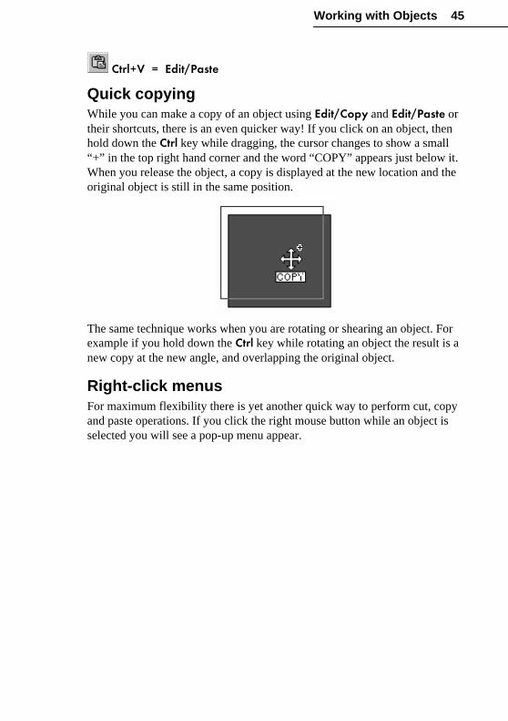
Working with Objects 45
Ctrl+V = Edit/Paste
Quick copyingWhile you can make a copy of an object using Edit/Copy and Edit/Paste ortheir shortcuts, there is an even quicker way! If you click on an object, thenhold down the Ctrl key while dragging, the cursor changes to show a small“+” in the top right hand corner and the word “COPY” appears just below it.When you release the object, a copy is displayed at the new location and theoriginal object is still in the same position.
The same technique works when you are rotating or shearing an object. Forexample if you hold down the Ctrl key while rotating an object the result is anew copy at the new angle, and overlapping the original object.
Right-click menusFor maximum flexibility there is yet another quick way to perform cut, copyand paste operations. If you click the right mouse button while an object isselected you will see a pop-up menu appear.

Working with Objects 46
DrawPlus uses right-click menus extensively, so the actual commands thatyou see listed depend on the type of the object or the area of the screen onwhich you right-clicked. You’ll find a complete listing of right-click menuoptions in online help (search “right-click menus” in the index).
Adding more objectsSo far all our examples have been concerned with selecting and manipulatinga single object. In a real drawing there are likely to be lots of objects.DrawPlus draws objects on the page in the order in which you created them.It’s easier to see this in practice than to read about it so it’s worth followingthrough this explanation.
1 Click twice on the QuickBox tool to access the QuickShapes flyoutand keep the QuickBox tool selected.
2 Click (don’t drag) near the center of the page.
Clicking without dragging produces a small defaultsquare colored with the default fill. Notice that thesquare is surrounded by eight handles, indicating thatthe Pointer tool is active and that this object isselected.
3 Select the QuickBox tool again. This time clickand drag a long, thin box that overlaps half of the
�

Working with Objects 47
original box, and extends below it as shown below.
4 The new rectangle is the same color as the square so let’s make it lookdifferent. Click to display the Color tab and click a different color in thesolid color gallery.
5 Now click the QuickBox tool once to open the QuickShapes flyout.
6 Select the second tool in the top row, the QuickEllipse.
7 The QuickEllipse draws ellipses and todraw a regular circle with it you simply holddown the Ctrl key while you click and dragacross the page. Select green from the Filltoolbar to change the appearance of thecircle.
8 Now select the QuickSplats tool from the QuickShape flyout, clickwith the mouse cursor positioned inside the circle and set its fill toanother color by selecting a different solid color from the Fill tab.
Notice that after you draw a QuickSplat, the Node tool, not the Pointer tool,is activated. We’ll cover that later but for now…
9 Select the Pointer tool and click on the“splat” to select it. Click on the splat againand hold the mouse button down so that theMove cursor appears. Move the splat sothat all four objects overlap as shown.

Working with Objects 48
Selecting overlapping objectsOnce you have a set of overlapping objects the job of selecting a specific onebecomes a little more complex. How do you select an object that is “behind”other objects? If the object you want to select isn’t completely hidden, thenyou could click on a portion of it where it is visible. Alternatively, repeatedlyclick with the mouse over the objects. Each time you click at the samelocation, a different object in the stack is selected, allowing you to select anyof the overlapping objects.
Let’s see this in action. First, click with the cursor somewhere in a blankregion so that none of the objects are selected. Now place your cursor at apoint where all the objects overlap. Click once and the object “on top” (thesplat in this case) will be selected. A second click at the same point willselect the next object, the circle in this case. A third click selects therectangle, the fourth the square and a fifth click takes us back to the firstobject, the splat.
Rearranging objectsAs we have seen, DrawPlus places objects on the page in the order you drawthem. It also lets you change this order using Arrange/Order Objects.

Working with Objects 49
There are four possibilities in this menu but not all of them are alwaysavailable. If you have selected an object that is on top of all others you willhave the options Send to Back and Back One - you can’t bring it forwardbecause it’s on the top level of the stack. If you have selected the object thatis at the bottom of a heap you will have the options Bring to Front orForward One. All the options are available for objects that are neither at thetop or bottom.
There are buttons for the ordering operations in the Standard toolbar.
Click on for Forward One and on for Back One. If you double-click on these buttons they do a Bring to Front or a Send to Backrespectively.
Selecting multiple objectsAs well as selecting a single object you can select more than one object atone time. A set of objects selected in this way forms a multiple selection thatyou can manipulate as if it were one object, or turn into a group object, as wewill discuss in Chapter 8, “Using Layout Tools.” For now, the question ishow to select more than one object at a time?
There are two ways. The first is to use the Pointer tool to draw a marqueebox around the objects you want to select. Drawing a marquee box is muchlike drawing a QuickShape rectangle. First select the Pointer tool, then clickand drag a box that surrounds all the objects you want to select. An outlineappears as you drag.
When you release the mouse button, all of the objects within the marqueebox are selected and one selection box, complete with handles, appearsaround the cluster of objects.

Working with Objects 50
The multiple selection can be sized, rotated, skewed, copied, deleted, and soon, in one operation as if it were a single object.
Another method of creating a multiple selection is to use the Shift key tomodify an existing selection. If you click on an object while holding downthe Shift key it will be added to the current selection. If the object is alreadypart of a group selection then it will be deselected. Using the Shift key youcan add objects to or take objects away from the current selection.
The Shift key also works if you use the marquee method of selecting multipleobjects. In other words, you can add or remove more than one object at atime from the current selection by dragging a marquee box around the objectswhile holding down the Shift key.
Using the PortfolioBy now, your workspace is probably cluttered with experimental objects ofall shapes, sizes, and types. Perhaps there’s even a grand design emergingfrom the chaos! But suppose you particularly like one or two of the objectsyou’ve created, and might like to use them again in a more (ahem)professional layout. Of course, you could reopen the saved file and retrieveobjects individually via copy/paste—but why work so hard when you can putthe DrawPlus Portfolio to work for you?

Working with Objects 51
The Studio’s Portfolio tab serves as a container for storing design objectsand elements you’d like to reuse in different documents. Once you’ve copieda design to your Portfolio, the design is available in any DrawPlus document.Simply display the Portfolio tab, and there it is!
Let’s try it. Click the Studio’s Portfolio tab. You’ll see it has an upperCategories group and a lower Designs gallery, each initially with a singlesample entry. Drag any one of the objects on your page and drop it into thelower gallery. A dialog pops up prompting you to supply a name for thedesign. Type something, click OK, and a thumbnail version of the objectappears in the gallery.
To use an object from the Portfolio, simply click its thumbnail and drag outonto the page. Try this now with the design you’ve just stored.
Right-clicking on the Portfolio gives you the option of renaming or deletingdesigns, as well as adding, deleting, or renaming categories. For more detailsand tips, search “Portfolio” in the online help index.
What’s Next?We’ve explored how objects can be created and manipulated. You can usethe techniques in this chapter to work with just about any object in DrawPlus.
The next two chapters will focus on specific objects, with more tips oncreating them as well as details on editing them. You’ve got all the basicinformation you need to begin exploring the creative possibilities ofDrawPlus.
�

Lines, Curves, andShapes

Lines, Curves, and Shapes 55
IntroductionIn Chapter 4 we introduced lines, curves, and shapes as variations of onebasic object: the line. They all consist of one or more line segments drawnbetween junction points called nodes. In general, if we use the word “line” itcan mean either a straight line or a curve—both are lines but with differentkinds of nodes at each end. A shape is a line whose ends have beenconnected to form an enclosed region.
You’ve also had a chance to use the three line tools...
Freehand
Straight Line
Curved Line
...to create simple lines and shapes. See the previous chapter if you need toreview the steps. Now, we’ll go on to explore how to modify lines and shapesthat you’ve drawn, and achieve precise control over the results.
The principles of editing plain lines, as described in this chapter, will serveyou well in our later discussions of special DrawPlus line types likeconnectors (Chapter 6), dimension lines (Chapter 8), and chain lines(Chapter 9).
Properties of lines and shapesLines can be either straight or curved. They have line properties like colorand weight (thickness). When you draw a new line, it takes on the currentdefault line properties; initially the default settings are for a solid black linewith a weight of 1.0 pixel.
Because shapes have an interior region that can be filled (for example, with asolid color or a bitmap), they have fill properties as well as line properties.The interior region takes on the default fill as soon as a line is closed tobecome a shape; initially the default setting is for a solid black fill.
For more on changing the line and fill defaults, and applying line/fill effects,see Chapter 7, “Line, Fill, and Transparency Effects.”

Lines, Curves, and Shapes 56
Extending and Redrawing LinesIf you haven’t already done so, now’s the time to reopen your testdocument—the one with an assortment of lines, curves, and shapes youcreated in Chapter 4. Or, you can start with a clean slate by opening a newDrawPlus document. Either way, we’ll assume you already know how todraw the basic lines and that you’re trying the examples in your owndocument as we forge ahead.
Extending a lineAny kind of open line (that is, one that hasn’t been closed to create a shape)can be extended, and you can use any of the three line tools to do so.
For example, suppose you’ve drawn a freeform line with the Freehand tool.When you release the mouse button the curve you’ve drawn is displayed withtwo red nodes at each end.
Now if you move the Freehand tool cursor over either of the nodes, a small +sign will appear. Click at that location, and the next line that you drag outwill be a continuation of the existing line.
Remember, you can use this technique with any kind of line and with any ofthe line tools to build up a long line. And by drawing a line between one endnode and the other, you can close the curve, creating a new shape!

Lines, Curves, and Shapes 57
Redrawing a lineThe Freehand and Straight Line tools let you redraw any section of a line.Try the following steps on any of the lines you’ve already drawn.
First you need to select the line you want to modify. Since the line tools can’tselect objects, you’ll need to either click the line with one of the threeselection tools (Pointer, Rotate, or Node), or press the Tab key repeatedly tocycle through the objects on your page, until the one you want is selectedwith handles.
Now choose the Freehand tool from the flyout. The line is still selected, butnow you can see its nodes. Move its cursor slowly in the vicinity of theselected line, and you’ll see the cursor change to include a curve shape toindicate where you can click to begin redrawing.
Pick a starting point somewhere along the line, then click and a new nodeappears immediately.
Keep the mouse button down and drag to draw a new line section, connectingit back to another point on the original line. Again, the cursor changes toinclude a curve when you’re close enough to the line to make a connection.When you release the mouse button, another new node appears at the releasepoint. The line you’ve just drawn replaces the portion of the original linebetween the two new nodes!
�

Lines, Curves, and Shapes 58
You can try the same thing on your own, using the Straight Line tool.
Editing CurvesSo far, we’ve covered the most direct ways of drawing, extending, andredrawing lines, using just the line tools. For even finer control, you can usethe Node tool and the Curve toolbar to edit curves (that is our catch-all termfor both simple and complex lines). The techniques involved are a bit morecomplex, but not really more difficult. In fact, the outcome depends less onyour eye-hand coordination and more on your having a clear idea of whateffect you want. With these two tools, you can get just about any effect youdesire!
You’ve no doubt noticed the Curve toolbar, which pops up automaticallyeach time you choose the Freehand tool. In Chapter 4, you learned how tosmooth a curve using the Curve Smoothness slider that’s part of the Curvetoolbar. Very shortly, we’ll discuss what all those little buttons do.
Reshaping a curve
First, let’s introduce the Node tool. Clickits button on the Standard toolbar, then click onany curved line on your page. (Make sure it’s acurved line, not a straight line.) As you mightexpect, the line’s nodes appear, and the Curvetoolbar also pops up.
To see what you’re doing in the next few steps, it will help to bezoomed in fairly close to the line, so click the Zoom In button if necessary.
Move the cursor over the line. You’ll see that when you’re over curvedsegments of the line, it says “SEGMENT.” Over a node, the cursor changesto include the word “NODE.” Over straight-line segments, it’s blank.

Lines, Curves, and Shapes 59
As with the other helpful cursors we’ve encountered, the extra informationconveys what you may expect to happen if you click at a particular point. Tryclicking and dragging one of the line’s curved segments. The effect is similarto redrawing with the Freehand tool, except that no new nodes are added—and as long as you hold down the mouse button, you can keep adjusting theshape of the segment until you’ve got it right. (And if by chance you don’tget it quite right, you can undo a change simply by pressing Ctrl+Z orclicking the Undo button.)
Now try clicking and dragging a node. By moving a node, you can repositionthe curved segments on both sides of the node.
If you simply click and release on a curved segment or a node, you select it—or more precisely, you select the adjacent nodes, leaving their controlhandles visible. Each line segment has two control handles, one on eitherside, that determine the path of the line segment between them. In the case ofa very simple curve with only one segment, here are the two handles:
Corner nodes join two segments, and so when you select a corner node yousee two handles sticking out from it. Each one helps to control the segment inthe direction it’s pointing. Here’s a slightly more complex curve with acorner node selected. You can see that there are two pairs of control handlesvisible, one for each of the segments joined at the selected node:

Lines, Curves, and Shapes 60
Once you realize that control handles work in pairs like this, it becomes easyto understand how to edit a curve. You can drag a node’s control handlesindependently to produce very precise changes in the curvature of the line oneither side. Try it yourself—our static illustrations can’t quite convey howthe lines behave. You can shorten or lengthen the handles, which changes thedepth of the curve (that is, how far out the curve extends), or alter the handleangle, which changes the curve’s slope.
If you look at any particular control node, you see its handles determine howthe curve will pass through it. If the two handles are in very differentdirections then the curve will slope (change direction) sharply as it passesthrough the control node.
Sometimes this is the behavior you want, but if you want a smoother curvethen you need to adjust the handles on either side of the node so that thecurve leaves the node at the same angle by which it entered. In other words,for a smoother curve the handles have to form a straighter line.
To keep the curvature the same on both sides of the control node, the handlesalso need to be kept at the same length as well as in the same direction.

Lines, Curves, and Shapes 61
Fine-tuning a curveReady for one more key bit of information about nodes? As we’ve just seen,when you select a corner node it displays one handle for each of the two linesegments joined there. When you adjust one of these handles, how the otherresponds depends on the node’s type. And there are in fact three types ofnodes. The difference between them is rather subtle, but worth understandingif you need to achieve maximum control over a line’s shape.
These are the three types of “corner” you can create: sharp, smooth, andsymmetric. You can tell at a glance which type of node is selected byinspecting the Curve toolbar to see which of the three buttons is down.Rather than having to minutely adjust handles individually to producesmooth and symmetric corners, DrawPlus will do the job for you. Simplyselect a node and click one of the three corner buttons on the Curve toolbar.
A Sharp corner means that the lines to either side of the node arecompletely independent so that the corner can be quite pointed. For example,here’s a curve (dashed line) with a sharp node in the middle. Dragging theleft segment has no effect on the right segment.

Lines, Curves, and Shapes 62
A Smooth corner means that the slope of the line is the same on bothsides of the node, but the depth of the two joined segments can be different.If (below) we change the middle node to a smooth node, dragging the leftsegment alters the slope but not the depth of the right segment. The handlesat a smooth corner rotate together, but you can drag one to be longer than theother.
Symmetric corner nodes join line segments with the same slope anddepth on both sides of the corner node. Below, with a symmetric node joiningthe segments, adjusting one segment affects both the slope and depth of theother. At a symmetric node the handles not only rotate as one, they changelength together.
To turn a curved line segment into a straight line segment, select thesegment and click the Straighten Line button. The selected segmentimmediately jumps to a straight line. To go the opposite way, click a straightline segment and then click one of the three corner node buttons. Then youcan adjust the curvature of the newly curved segment.

Lines, Curves, and Shapes 63
Adding and removing nodesYou already know that extending a line by drawing with any of the line toolsadds one or more new segments and nodes off the end of the line. You canuse the Node tool to add or subtract nodes in the middle of a line, as well.
To add a new corner node, simply double-click the point on the line whereyou want the node to appear. Adding a node can be useful if the curve onlyneeds a slight change, because it provides an additional pair of controlhandles to adjust.
Sometimes it’s a good idea to remove control nodes that aren’t reallynecessary to form the shape of a curve. After you’ve drawn a freeform linewith the Freehand tool, as long as the line is selected, you can use the CurveSmoothness slider (as described in Chapter 4). Or you can chooseTools/Clean Curves to have DrawPlus strip away extra nodes (see below).After that, you can continue the process by hand if necessary, selectingindividual nodes and then using the Curve toolbar’s Delete Node button.When a node is removed, the curve is drawn between the remaining nodeswithout making any changes to their handles.
Closing, opening, and joining curves
Sometimes you’ll want to turn an open curve into a closed curve (ashape, in other words), or you may accidentally mis-draw a shape, leaving anopen curve. The solution in both cases is to use the Close Curve button fromthe Curve toolbar. This draws a straight line between the first and last controlnodes. If you don’t want the curve closed by a straight line, then you can usethe Curve toolbar afterwards to convert the segment’s control nodes to asmooth or symmetrical corner.

Lines, Curves, and Shapes 64
You can’t use the Close Curve button to join nodes in two different curves.Instead you need to select the two curves you want to join, then use theTools/Join Curves menu command, which will add a straight line betweenthe last and first points of the two curves. To close the resulting curve orchange it in any way, use the Curve toolbar.
Finally, if you want to open a curve or break a curve into pieces youselect the node where you want to create the break and click on the Break Curve button. You can use this as many times as you want to convert aconnected curve into separate segments. Notice that when you first break acurve the two control nodes are in exactly the same location and so the curvemay still look as if it is connected. If you drag one of the control nodes awayyou will quickly see that it isn’t.
Cleaning curvesVector clipart is made up of curves that you can edit using the Node tool.This is the best way of customizing it to fit with your drawing. The problemis that often when you ungroup a clipart drawing and try to edit the curvesthat make it up, you discover that there are far too many nodes on even asimple curve.
This overabundance of nodes only matters if you want to edit the curves. Youcould use the Node tool to delete unnecessary nodes but it makes more senseto select the curve and use the Tools/Clean Curves command. This scansalong the curve and removes any node that isn’t really needed to determinethe shape of the curve. Afterwards, the result should be a curve with asmaller number of nodes and one that is much easier to work with.

Lines, Curves, and Shapes 65
Converting to Curves
Now that you know how to edit a curve, you may wonder how you cando the same things to a QuickShape, or to text for that matter. The problem isthat the Node tool affects a QuickShape objectand a text object quite differently from the wayit edits curves. Most of the time this is exactlywhat you want, but occasionally it would benice to edit an outline as if it were a simplecurve. The solution is the Tools/Convert to Curves menu command or the Convert to Curves button on the Standard toolbar.
Once a QuickShape or a text object has been converted to curves, you canedit its outline using the Node tool—but it loses all of its special properties.Converting text to curves is one way of incorporating letter shapes intodesigns, and converting QuickShapes provides you with a starting point foryour own shapes.
When you convert an object to curves the outline is automatically subjectedto a Clean Curves operation to reduce the number of nodes and make it easierto edit. If you like, you can turn off this feature on theTools/Options.../General tab.
PROJECT: A Simple MapHaving worked through a lot of very small examples, it’s time to put varioustechniques together and actually create a whole drawing. So save your testwork and choose File/New to open a blank document.
One of the best things about using DrawPlus is that even if you can’t drawwith pencil and paper, you will be able to create drawings that look just theway you imagine them. The most important thing to realize is that you don’twork in the same way as a traditional artist would create the same drawing.
This may sound obvious because you are working with a computer, but atfirst it is difficult not to think in terms of drawing and rubbing out yourmistakes—don’t! Using DrawPlus, you assemble a drawing from smallobjects that you edit to make them just right. So stop worrying about how todraw like an artist and discover how to draw with DrawPlus!
�

Lines, Curves, and Shapes 66
Roughing itDrawing a map of where you live or work is something most of us have to dofrom time to time—usually in a hurry! If the idea of drawing a map soundslike hard work with lots of lines to put in the right place, then don’t worrybecause DrawPlus makes it easy.
The first part of our map is a rough sketch of the roads, and for this we willneed to use the Freehand tool, the one that looks like a pencil (you mayremember it from earlier in the chapter). It not only looks like a pencil, itworks like one too. To draw a line, you simply move the mouse whileholding down the mouse button. Try it out again with a few freehandscribbles.
Scribbling is fun and easy but you also need to be able to keep it undercontrol. Practice drawing some curves and alter the speed with which youmove the mouse. The slower you draw, the more detailed the line becomes.Faster, larger movements produce smoother curves. Don’t worry aboutdrawing accurate curves, though, because it is very easy to edit what youhave done.
When you have finished experimenting you will want to clear the page. Todo this select all of your lines, press Ctrl+A (or choose Edit/Select All andpress the Delete key.
Roads under constructionNow use the line tools to sketch some lines that represent the roads closest toyour house or office. You don’t have to copy our illustrations—in fact, youcan try to improve on them!
Use the Freehand tool when the roads are irregular
and the Straight Line tool for any roads that are regular.
� Holding down the Shift key constrains straight lines to angles of 15degrees.
Draw each road as a separate line. The result will probably not be exactlywhat you hoped for, but don’t be panicked into erasing the sketch—unlike ascribble on paper it can be edited to look good!

Lines, Curves, and Shapes 67
Road improvementsEven if you are using different colors for types of road, it is helpful to useline weight (thickness) to distinguish the major roads from the minor ones.This is easily done by selecting each of the lines representing major roadsand choosing a suitable weight, such as 5pt, from the Line Weight box on theStudio’s Line tab. Repeat for the lines representing the minor roads, but usinga thickness of 2.5pts.

Lines, Curves, and Shapes 68
Use the Freehand or Straight Line tools as discussed earlier in the chapter toredraw any sections of road that didn’t turn out quite right. Select the linefirst with a selection tool, then click anywhere with the line tool to “cut” theline at that point and insert a new section.
You can also use the Node tool to edit the lines to give them the correctcurves and make them join at the right places.
For example, delete surplus nodes to clean up lines that have accidentalbends. Select each of these nodes in turn and choose the Delete Node buttonfrom the Curve toolbar.
Using the Node tool you can manually select any of the nodes or segmentsand move them to change the shape of the line. So if the line doesn’t stopquite where it should, just pick up the end node and drag it where you wantthe line to finish.
House buildingTo show the exact location of your house or office, we need a symbol for thebuilding. You could look for one, or put one together, from QuickShapes buthere we will use the Straight Line tool to review how to construct a shapefrom line segments.
� Make the snapping grid visible with View/Layout Tools/Snapping Grid before embarking on drawing a house. You can either keepsnapping on, or turn it off, using the Snapping button on the Hintlinetoolbar. Either way, the dots will serve as a guide.
Choose the Straight Line tool from the flyout, then click and hold down themouse button at the starting point of the line and drag to its finishing point.The nodes at either end of the line appear when you release the mouse button.It is important when you are creating a closed shape from a line that the lineends meet! Watch the cursor. The small “+” sign indicates that clicking anddragging will extend the line, and the small box tells you that clicking in thatspot will complete the closed shape.
Draw five straight line segments, connecting them to extend the line as yougo, to make a house shape. Finish the last line (closing the shape) at the samenode that begins the first line.

Lines, Curves, and Shapes 69
You’ll know you’ve successfully closed the line and created a shape if it fillsright away with the default fill.
The house can be drawn anywhere on the page or pasteboard because it’seasy to move it to its final position. You can also change work at any zoomlevel that makes it easy to draw because the figure can be scaled to any finalsize. Just select it with the Pointer tool and drag from a corner handle.Objects are often easier to draw large and in this case you can use the dots ofthe snapping grid to align the points of the house shape.
Tearing the roof offLet’s try filling the roof with a different color to distinguish it from the rest ofthe house. To do this we need to make two objects from the one we havenow. We’ll break off the roof and house from each other, then close each ofthe separate shapes. First, select one of the nodes that join the roof to thehouse and click the Break Curve button on the Curve toolbar. At this point,although it may still look as if only one node exists, you will see the houselose its fill since only closed shapes can be filled. We now have a line with itsstart and end nodes at exactly the same point.
Repeat this on the other connecting node so that the roof is completelyseparate. At this point you could move it away from the house shape if youwanted to. Instead, close the roof as a separate object by selecting either of itstwo segments with the Node tool and clicking the Close Curve button. Theroof will fill as a separate object. Do the same to the base of the house.

Lines, Curves, and Shapes 70
Repeat the closing procedure for the house shape. Now you have two closedshapes with the same fill. Select either one and apply a new fill color usingthe Fill tab.
Save your work—we’ll return to the map mini-project in Chapter 8. Rightnow, it’s time to move along and consider other kinds of objects.

QuickShapes,Connectors, Text,and Pictures

QuickShapes, Connectors, Text, and Pictures 73
IntroductionYou’ve already seen how a DrawPlus drawing is made up of several differentkinds of objects. In Chapter 4, “Working with Objects,” we introduced thethree basic object types and saw how to change the way they look byresizing, positioning, and rotating. Chapter 5 dealt extensively with the firsttype of object (lines). This chapter will focus on the three others—QuickShapes, onnectors and text objects—and explore a variety of ways tocustomize them. In addition, we’ll take a quick look at OLE objects thatallow DrawPlus to be linked to other Windows applications.
QuickShapesQuickShapes are pre-designed objectsthat you can instantly add to your page,then adjust and vary using controlhandles. The QuickShape flyout containsa wide variety of commonly used shapes,including boxes, ovals, arrows, polygonsand stars.
Each QuickShape in the flyout has its own built-in, “intelligent” properties.In some cases, varying the QuickShape produces related shapes, such asforms of transport or zodiac signs. In others, you can drag to customize abasic shape like a polygon or star.
When you select most QuickShapes, rather than being surrounded by aselection box and handles, they display one or more sliding handles, whichare used to control aspects of the shape. Some QuickShapes have morehandles than others. For example, a QuickPolygon has two:

QuickShapes, Connectors, Text, and Pictures 74
Editing QuickShapes
The previous chapter introduced the Node tool and explained how itworks with lines, curves, and shapes made from lines. The Node tool isselected automatically after you finish drawing most QuickShapes, but itworks somewhat differently here. To vary a QuickShape, you simply dragone of its handles with the Node tool.
For example, try creating a QuickBox and dragging its handle. You’lldiscover that it produces round corners—either inward- or outward-pointing.If you drag on the first of the QuickEllipse handles you will find that it opensup a segment; the second handle rotates the position of the “opening.”
Some QuickShapes have more than two handles. For example, theQuickStar has four, which allow you to create everything from a traditionalfive-pointed star to an incredible crystal snowflake!

QuickShapes, Connectors, Text, and Pictures 75
The best way to find out about the amazing range of QuickShapes that’savailable is to experiment with each of them. Check the HintLine for a briefdescription of what each handle does. Try them out and make sure you seethe effect of changing each of the sliding handles.
Clever though the QuickShapes are, it is worth remembering that they alsobehave like standard objects. You can still use the selection tools to move,rotate, scale, and change their fill and line properties (see the next chapter).Even after rotation and shearing, the sliding handles can still be used tomodify the shape.
QuickShapes are one of the basic building blocks of DrawPlus designs. Theylend themselves to a wide variety of special effects, as described in Chapter9. And for some exciting ways to use QuickShapes for creating animatedWeb graphics, see Chapter 10.
ConnectorsConnectors are special lines that you can anchor to objects, where theyremain attached even if one or both objects are moved or resized. Usingconnectors, you can easily create dynamic diagrams and charts that showrelationships, such as family trees, organization charts, and flow charts. Ifyou need to rearrange the elements, the connections are preserved. Let’s takewhat you’ve just learned about QuickShapes and see how easy it is to applyconnectors.
If you’ve been experimenting with QuickShapes, you can use any two thatare already on your page. Otherwise, draw two separate QuickShapes now.For illustration purposes, we’ll assume you have two QuickBoxes side byside as shown below, and refer to them as the “left” and “right” shape.

QuickShapes, Connectors, Text, and Pictures 76
Click the Connection Tool flyout button on the Drawingtoolbar and select the first button for the Direct Connector tool.Immediately, default connection points become visible on all page objects.In a moment, we’ll see how to add new connection points... but let’s moveright along and connect the dots.
Using the Direct Connector tool, click the connection point on the right edgeof the left shape. Drag to the right and release the mouse button when thepointer is over the connection point on the left edge of the right shape.(You’ll see a box appear around the point when a connection is imminent.) Adirect connector appears between the two connection points.
Now choose the Pointer tool; the connection points vanish, but the connectorremains. Click the right shape to select it, then drag the shape to a newposition. The connector follows!
We could have attached either end of the connector to any of the visibleconnection points, or even kept it free-floating (in which case it would beanchored to a point on the page). To re-anchor, simply select the connectorwith the Node tool and then drag one of the end nodes over a connectionpoint of the object.
With one shape slightly above the other, choose the Node tool and select theconnector; the connection points become visible again. Click the connector’sleft end node and drag to the connection point on the left shape’s top edge.Release when the small box appears, and the connector re-anchors.

QuickShapes, Connectors, Text, and Pictures 77
By the way, the central connection point is special. It’s called the AutoSelect connection point because a connector which was anchored there willalways draw using the connection point that results in the shortestconnector—in other words, the one nearest to the other object. Try using theNode tool to re-anchor your connector to the Auto Select point on bothshapes (notice how the object highlights when the node is over the Autoselect point). Now move each object around freely and you’ll see how theauto select behavior works.
What if you want to anchor a connector to a specific point on an object, butit’s not one of the default connection points? That’s where the ConnectionPoint tool comes in handy.
Click the Connection Tool flyout again and this time select the fourthbutton. This time, the default connection points only appear on any selectedobject(s), so you may or may not see any. So click one of your shapes toselect it and display its connection points - an “X” cursor is shown when themouse is over the object. Then click somewhere in the interior of the shapeand a small symbol appears denoting a new, custom connection point. Youcan add custom connection points anywhere but typically you will want thempositioned around the perimeter of an object.
You can select and move custom connection points with the ConnectionPoint tool. To delete one, simply select it and press Delete. Otherwise, theyfunction basically like default connection points.
The Right Angle Connector tool creates connectors that use onevertical and one horizontal segments so the connector shape is a right angle.Delete your existing connector and use the right angle connector tool tocreate a new connector.
�

QuickShapes, Connectors, Text, and Pictures 78
When creating a right angle connector, the first segment of the line is alwaysvertical and the second segment is always horizontal. So, if the connector youcreated has the segments the wrong way round, delete it and try again, thistime reversing which connection points are used for the start and end point ofthe connector.
Suppose you decide you should have drawn your right angle connector usinga direct path. Rather than redraw, you can convert. Select the connector andthen right-click it. Choose Connectors from the context menu and selectDirect Connector from the submenu and the connector redraws using its newshape. Now right-click the connector and change it back to a right angleconnector.
When creating connectors, you can specify either Direct or Right Angle—oryou can utilize the most powerful of all, the Auto connector. Autoconnectors will automatically assume a shape of the best fit for a particularpath, given the objects’ placement and the connection points you’ve chosen.They only use horizontal and vertical line segments and can even routethemselves around objects that are in the way. Let’s try another experiment.
Draw another small QuickBox where the current connector makes its right-angle bend. Because the connector is still of the standard Right Anglevariety, its path doesn’t change.
Now change the connector to an Auto Connector: right-click it, chooseConnectors, then Auto Connector. Immediately the line finds a way toavoid the obstructive box! The auto-connector will redraw to a new shapewhen ever any objects are moved or resized and the shape it assumes will useas many line segments as necessary to find a path between the two objects.
�

QuickShapes, Connectors, Text, and Pictures 79
Auto connectors are intelligent in another way: they know when they’vecrossed one another, and form “bridges” as needed to keep the connectorlines separate, as shown here:
The Layout tab of the Tools/Options... dialog includes settings that let youadjust the allowed separation between Auto connectors and page objects, aswell as the size and spacing of bridges. (Search “connectors” in the onlinehelp Index.)
For a final demonstration of how versatile connectors can be, right-click thesmall box that was getting in the way. Choose Connectors, and then uncheckObstructive Object. Now the Auto connector ignores the box and resumesits earlier, simpler shape. New DrawPlus objects are always obstructive bydefault—but you may wish to turn the property off in individual instances.
You can edit connector properties like thickness, color, and line ending justlike those of standard lines, as covered in the next chapter. And you can editthe shape of connectors using the Node tool (again just like regular lines, ascovered in the previous chapter) if a different shaped path is desirable.Reshaped connectors become “Custom Connectors,” losing their Autoproperties so you may need to adjust the route to avoid other objects. On astylistic note, a given diagram or chart will look better if you can find onesuitable connector style and use it consistently, rather than trying to exploitall the options in one document.
Take a look at the Library tab’s “Connecting Symbols” category for an arrayof basic shapes and chart symbols that you can use as starting points.
�

QuickShapes, Connectors, Text, and Pictures 80
Text
Although text objects might seem different from other objects, in manyways they work in a similar manner. You can place text anywhere on thepage by selecting the Text tool and clicking at the desired location. Ablinking text cursor appears and you can type directly on the page.
If you simply click on the page with the Text tool, thecursor will be at the default size, but if you click anddrag you can size the text cursor before you type.
If you press the Enter key while typing, you can typemultiple lines of text as a single object.
Once you have finished entering text you can select it using either the Pointertool or the Rotate tool and modify it just like any other graphics object. Youcan scale, rotate, skew, move, and copy it, and apply fills, line styles, andtransparency (see the next chapter).
Text propertiesText objects in DrawPlus have the same text attributes you would expect tofind in any text application—including font, pointsize, style, line color, fillcolor, line weight, letterspacing, line spacing (leading), and alignment. Newtext automatically takes on the default settings for text, which are separatefrom those for lines and QuickShapes. You can define some of theseproperties using the Text tab, others by using the built-in Edit Text window.
Click the Text tab to show the available controls. In Chapter 4, we triedcreating some text and you saw that the font list lets you preview fontappearance as well as apply a font to selected text. The pointsize drop-downlist shows the vertical size of the selected text in points. (The point is atraditional measure of the size of text; there are 72 points to the inch.) Ifyou’ve changed the size of text by dragging its handles, you may end up withdistorted text that doesn’t correspond exactly to the font you have chosen atany pointsize.
�

QuickShapes, Connectors, Text, and Pictures 81
You can use the drop-down list to select a specific size.
If you click on the font style buttons then the currently selectedtext will be displayed with the selected effect.
The four alignment buttons let you align text objectswith multiple lines. If you click on the first button the text is left aligned, thesecond centers each line, the third right aligns the text, and the final buttonjustifies the text.
Selecting a text object with the Node tool displays right- and down-arrow control handles. To set tracking (space between characters), drag theright arrow.
To adjust leading (space between lines), drag the down arrow. To controlcharacter positioning precisely you can drag the small square handles at thebottom left of a character. To move a single character around, drag the handlejust to its left. To rotate a single character, click its handle and drag the uppernode (blue dot) to either side. This is great for creating special effect andlogos and the text can still be edited with the Edit Text dialog box (seebelow).

QuickShapes, Connectors, Text, and Pictures 82
Right-clicking on selected text and choosing Spacing... brings up a dialogthat lets you set text alignment and fine-tune leading and tracking. You canset the width of each character as a percentage of its standard width or inabsolute units.
Editing textIf you want to edit the actual text of a text object then you can either double-click on it with the Pointer tool or click on it using the Text tool. The EditText window opens and you can enter new text or change the existing text.

QuickShapes, Connectors, Text, and Pictures 83
The Edit Text window also lets you apply different effects: fonts, pointsize,bold, and italics. Select the letters or words you want to change with thecursor, just like you would in a word processor, and then use the buttons onthe toolbar to apply properties to it.
The Draft button is used to switch between draft view, useful forviewing a lot of text at once, and formatted view, which shows how the textobject will look on the drawing.
When formatted view has been selected, the Zoom box allows you to view itat a number of zoom levels.
To return to DrawPlus, click:
the Accept button to update, or
the Cancel button to abandon changes.
Special text effectsDrawPlus includes a bevy of features that you can use to create incredibletext effects:
♦ Fill and transparency. Explore the wide range of possibilities availablein the Studio.
♦ Shadows. Using the Shadow flyout on the Standard toolbar, it’s easy toadd a drop shadow to a text object, then use the Shadow tool and dialogto customize it.
♦ Combination effects. Use Combine, Crop, or Join to create “mask” or“stencil” effects and new hybrid shapes incorporating text and/or otherobjects.
♦ Text on a curve. Use the Curve Text Wizard or the Curve Text flyoutbutton to make text conform to a curved baseline.
♦ Enveloped text. Use the Envelope Wizard or the Envelope flyout buttonto flow text into any outline shape.
♦ Perspective. Choose a preset from the Perspective flyout, then dragfreely to customize the “3D-like” deformation.
♦ Text art. Explore the customizable designs available on the Studio’sLibrary tab.

QuickShapes, Connectors, Text, and Pictures 84
We’ll be looking at fill and transparency in Chapter 7, and the other specialeffects in Chapter 9.
Pictures
There are two basic types of pictures that you can place into DrawPlus.Bitmap pictures (including .BMPs, .GIFs, and .JPGs), also known as paintor raster images, are built from a matrix of dots (“pixels”), rather like thesquares on a sheet of graph paper. They are typically created either by using apaint type program such as Microsoft Paint, or by using an image scanner toconvert photographs. If you can see a square in a bitmap picture it is acolored area in the shape of a square. You can’t select it and change it. Muchof the work of creating or editing a bitmap is typically done in a separateprogram called a paint editor.
The next chapter, “Line, Fill, and Transparency,” includes more informationabout manipulating bitmap-filled objects in DrawPlus, and online help has allthe technical information you’ll need on exporting to different formats. Formore information on specific bitmap formats, see Chapter 10.
Vector graphics, also known as draw graphics, are resolution-independentand contain drawing commands such as “draw a line from A to B.” These arelike DrawPlus drawings, made of many individual objects grouped together,and you can edit them in the same sort of way.
Importing picturesDrawPlus lets you import any industry-standard bitmap file and a wide
variety of vector files. Click the Import Picture button on the Drawingtoolbar. Use the file selection dialog to browse files and select the file toimport, then click OK. The dialog disappears and the mouse pointer changesto the Picture Size cursor. What you do next determines the initial size,placement, and aspect ratio (proportions) of the image.
♦ If you want to insert the picture at a default size, simply click the mouse.
♦ If you prefer to set the size of the inserted picture, drag out a region andrelease the mouse button. (Normally, the picture’s aspect ratio ispreserved. To allow free dragging to any aspect ratio, hold down theShift key. To constrain the aspect ratio to a square, hold down the Ctrlkey.) You can always resize a picture as required, after it’s been placed,by dragging its handles.
�

QuickShapes, Connectors, Text, and Pictures 85
If your scanner or digital camera provides TWAIN support, you can scanpictures directly into DrawPlus. To set up your TWAIN device for importing,see the documentation supplied with the device for operating instructions. Toimport an image, choose TWAIN from the Insert menu, then Acquire fromthe submenu to open a file selection dialog.
When you import a bitmap picture into DrawPlus, it becomes the Bitmap fillAs with other object fills, you can add these bitmaps to the Bitmap fill galleryto be used as fills for other objects (see Chapter 7). For fun special effects, tryusing Photo Wizard, the built-in DrawPlus photo editor, to adjust an object’sbitmap fill (see the next section).
When importing a vector graphic, DrawPlus converts it into individualline/shape objects, and you have the choice of ungrouping the objects inorder to edit them further, or leaving them as a group.
You can also use “autotracing” to import a bitmap as a vector graphic.Choose Bitmap as Vector... from the Insert menu and select the file toimport. You can adjust smoothness and tolerance settings while previewingthe resultant image in the dialog prior to importing.
In any case, the imported picture ends up as an object you can select, move,scale, shear, rotate—and even crop using the Envelope flyout on theStandard toolbar.
Photo WizardIf you’ve imported a photographic image, or you’re looking for a way toenhance Bitmap fills, you will appreciate the extra power of Photo Wizard,the built-in special effects editor for bitmaps. Photo Wizard lets you alter thepicture’s appearance in a variety of unusual ways. To run Photo Wizard, allyou have to do is to double-click on the bitmap-filled object, or access it fromTools/Photo Wizard.

QuickShapes, Connectors, Text, and Pictures 86
All of the tools work in the same way as DrawPlus and you can see theirtooltip descriptions by moving the cursor over them.
Click the Help button for self-contained online help on Photo Wizard.
You apply a tool by clicking itsbutton and you can setprecisely how it works bydouble-clicking it.
The top panel of tools are concerned with special effects and improving thelook of an image. For example, the Mosaic filter will break the picture upinto small squares and make it look like a tiled mosaic.

QuickShapes, Connectors, Text, and Pictures 87
If you are trying to improve the look of a scanned photograph, try theSharpen filter and the Remove Noise filter. There are other filters forimproving the look of photos in the second panel.
These filters control the more technical details of a photo. For example,and increase the brightness and contrast of the photo much as thebrightness and contrast controls on your TV affect its picture. You can alterthe color balance and even convert a color picture into black and white.
The third panel of buttons flip, rotate, resize, and crop the photo.
The next panel includes the familiar Cut, Copy, Paste, and Undo tools.
The final panel controls the zoom. One of these buttons is selected accordingto the current zoom factor.
The tool at the far right will draw a graph of the colors in the photo. This canbe a useful guide to how to adjust the color balance and contrast.
To return to DrawPlus, click:
the Accept button to update, or
the Cancel button to abandon changes.
OLE ObjectsAs well as pictures, you can insert a very wide range of object types into yourDrawPlus page. Most Windows applications support a standard calledOLE—Object Linking and Embedding—which allows objects created by oneapplication to be inserted into another.
The command Insert/Object produces a dialog box which lists all of theOLE supporting applications installed on your machine.

QuickShapes, Connectors, Text, and Pictures 88
You can edit an OLE object by double-clicking on it. Alternatively you canuse the Edit/Object command, which will contain a new item correspondingto the name object you have inserted.
Editing an OLE object is something that is delegated to the application thatcreated the object. So, if you insert an Excel spreadsheet object into a pageand then double-click on it, Excel is started and you will see Excel’s menuand commands.
DrawPlus drawings as OLE objectsAs well as being able to insert OLE objects into a DrawPlus drawing, youcan also insert a DrawPlus drawing into another application that supportsOLE. For example, if you are preparing a document with a desktop publisherlike Serif’s PagePlus you can insert a drawing from DrawPlus into the layoutto illustrate it. To do this, click the Insert DrawPlus Object button on thePagePlus Tools toolbar. Then click again on your PagePlus page, or drag outto indicate the desired size of the DrawPlus object.
Alternatively, you can select the object (or all objects using Edit/Select All)and then copy to the Clipboard using Edit/Copy. In the other application thedrawing can then be inserted using Edit/Paste or Edit/Paste Special.
Or you can use the other application’s Insert/Object command to insert anew DrawPlus object or a drawing already saved in a file.
It doesn’t matter how the DrawPlus object gets into the document; double-clicking on it will start DrawPlus and allow you to edit it.

QuickShapes, Connectors, Text, and Pictures 89
Exporting Drawings as PicturesExporting a drawing as a picture is one way of working with applications thatdon’t support OLE. When you save a drawing DrawPlus uses its own formats(.DPP for drawings and .DPA for animations) to store the information. To beable to read the drawing into another application it has to be saved in one ofthe many standard formats. You can do this using the File/Export... command.
There are lots of formats to choose from, but notice that in general you willnot be able to read the exported file back into DrawPlus and edit as easily asthe original. If you export the drawing to a bitmap picture any details of theobjects it contained are lost forever. So if you want to work with yourDrawPlus drawing again make sure you save it in DrawPlus format as well asexporting it in a format that the other application can use.
For more information on exporting, see Chapter 10’s section on “OptimizingGraphics.”
PROJECT: Building a Business CardNow that we know more about QuickShapes, text, and importing pictures, wecan get down to serious work and design a business card. It’s likely that youwill want to work on one of your own rather than reproduce the samplewe’ve produced. So, rather than take you through it step-by-step this time,we’ll start with a finished drawing and then look in detail at how it wasproduced.

QuickShapes, Connectors, Text, and Pictures 90
Working to sizeA typical business card is creditcard-sized. Working on your normalpaper size, the first thing to do is touse the QuickShape tool to draw arectangle to the size required. Thenopen the Status tab, either byclicking on the Status tab button onthe HintLine toolbar or right-clicking on any toolbar or Studio tablabel and checking Status tab on themenu.
Fill in the values you require for width and height in the edit boxes ofthe Status tab. Close the Status tab using the Windows close box in the topright.
You need to be able to see your business card close up as you work on it.There are a number of zoom options on the HintLine toolbar. Clicking theActual Size button is one solution. The other is to click on the Zoom tooland use it draw a box around the area that you want to fill the entire screen.This makes your view rather larger than life-size, which makes it easy to dealwith fine positioning.
A suitable backgroundNext consider the color of the card that you are going to use when you finallyprint your business card. Although this background will not itself be printed,it’s important that you adopt a similar shade while working on the design inorder to choose the correct colors and shades for other elements. Here wefilled our QuickBox with a cream color by clicking a thumbnail in the StudioColor tab’s solid color gallery.
Make sure to have the object selected before you apply changes from theStudio galleries. If no object is selected, your Studio choices only change thedefault settings for the next new object you create.
�

QuickShapes, Connectors, Text, and Pictures 91
Initially, new QuickShapes are created with a default line of “None.” In thiscase, it will be helpful to see where the edge of the card is. To do this, selectthe Studio’s Line tab and choose “1.0” (instead of “None”) in the LineWeight box. Assuming black is currently the default line color, that’s all youneed to do. To change the line color, select the Studio’s color tab, right-clickon the desired color and select Set Line Color.
Putting QuickShapes to workAs you can see, there’s a lot more to QuickShapes than drawing simpleboxes. A box can be instantly changed. To achieve rounded corners on thebusiness card, simply select the box with the Node tool and drag the slidinghandle (which appears on a line to the left of the box) upwards. If you look atthe HintLine while moving the node handle it tells you the changing radius ofthe corner. We used a value of about .3 inches.
Given the fictitious company name “Arrow Air,” an arrow is an obviousshape to incorporate in the design. There are various QuickShapes for arrows.
This one is based on the QuickArrows shape, and the Node tool wasused to select one of the variations supplied. We drew the shape on thepasteboard and it appeared with the current default fill color, black. (Yourdefaults may differ.) Then we moved and resized the QuickShape into a moreor less final position.
TIP: Use the Snapping button on the HintLine toolbar to turn snapping off togive more flexibility in positioning objects in this small working area. Howto control the snapping grid will be discussed in Chapter 8.
The airplane in this design is also from the QuickShape palette. Select theQuickTransport button and click on the page. Itstarts off as a helicopter but if you then drag thesliding handle to the left you’ll obtain this airplane.Give it a solid black fill and this time lighten it bydragging the Tint slider up to about 50%. (You canalso type exact values next to the slider, then pressEnter to update the object.)
Clipart is a good source of graphics for a design like this one. We draggedand dropped in a clipart globe, then sized and positioned it in DrawPlus.

QuickShapes, Connectors, Text, and Pictures 92
Adding text
Text is obviously a very important element in a business card design. It needsto convey information clearly, but can have decorative value itself. We addedtext with the Text tool, Text tab, and Edit Text window as described earlier inthis chapter.
First, we entered the company name, which was left at the default of 24-pointArial. Next, we entered the personal details as a four-line text object usingtwo different fonts (Arial for the name and e-mail address and Times NewRoman for the phone and fax numbers) and different pointsizes (11pt forname and address, 9pt for phone and fax numbers, and 10.5pt for the e-mailaddress). Bold and italics were used throughout. Arial and Times NewRoman are standard Windows fonts. You can choose from any availablefonts on your own system.
Initially, we typed text onto the page. Then the Edit Text window was used toalter the entries slightly, and to type the message, which was set to 14ptBalloonist SF.
Then we used the Curve Text tool (see Chapter 9)to give the text a semi-circular shape. It was thenmoved and sized into position on the drawing.

QuickShapes, Connectors, Text, and Pictures 93
This completed the design and the business card drawing was saved to disk.
Using the design elsewhereIt is a simple matter to use the drawing as an OLE object in otherapplications, simply by copying it to the clipboard and then pasting it into anopen document in the other application.
Although we started with the idea of creating just a business card, the designhas potential for use in other documents such as letterheads, faxes, andmemos etc.

Fill, Line, andTransparency Effects

Fill, Line, and Transparency Effects 97
IntroductionWe’ve seen how to create and manipulate all the basic types of objects—lines, shapes, QuickShapes, and text. Along the way, we’ve had occasion touse the Studio’s Color tab to apply different solid color fills. But there’smuch, much more in store in the Studio. It’s time now to examine how youcan use the Fill, Color, Line, and Transparency tabs to apply a remarkablevariety of effects to all kinds of objects.
Colors, of course, are fundamental to fill and line effects, so we’ll alsoprovide details on how to manipulate colors in DrawPlus—whether usedindividually or as part of color schemes. So follow along and work throughthe examples, and you’ll emerge with a new awareness of the creativepossibilities.
Fill Settings
The Fill tabClick the Studio’s Fill tab and let’s look at its elements. Here’s what the tablooks like if you drag it (by its “Fill” label) to detach it from the Studio as afloating window:
�

Fill, Line, and Transparency Effects 98
The most conspicuous feature is the gallery, a scrolling array of differentfills. Just below the label, there’s the Fill Type drop-down list, which lets youselect a particular category of fill (we’ll cover those categories in a moment).Above, you can see that the Linear category is currently selected. Next to thelist is the Add Fill button, which lets you add fills to the gallery, and justabove the gallery are the Tint slider and Value box, which together let youvary the shading of a fill on a particular object.
Types of fillsAny closed shape, such as a closed curve or QuickShape, and any text objecthave an interior region that can be filled. In Chapter 3, we briefly looked atsolid fills, those that use a single color (set by usingthe Color tab), and we’ve mentioned that the defaultfill is solid black. Later in this chapter we’ll discusshow to add your own custom colors, or change thosealready in the Color tab’s gallery.
All the other fill types are located on the Fill tab. If you click the Fill Typelist, you’ll see them listed at a glance. Let’s take a moment to run throughthem.
There are eight fill types collectively known as gradient fills, because theyprovide a gradation or spectrum of colors between two or more “key” colors.The fills, shown above, are named (top row) Linear, Radial, Ellipse, andConical; (bottom row) Square, Three-Color, Four-Color, and Mesh. As agroup, gradient fills all behave in basically the same way. However, meshfills are especially complex and will get a separate section in this chapter.

Fill, Line, and Transparency Effects 99
Bitmap and Plasma fills (above) apply bitmapped images or patterns to theobject. You’ll recall from the previous chapter that bitmap pictures youimport into DrawPlus become the Bitmap fill for a new box shape. So it mayhelp to think of Bitmap fills as named “pictures” that fill shapes. Plasma (or“fractal”) fills use randomized patterns, useful for simulating cloud orshadow effects. As we’ll see, Bitmap and Plasma fills have some uniqueproperties.
Applying a fillApplying a fill is easy, whether you’re using the solid colors from the Colortab or the more complex fills from the Fill tab. Let’s try it. Click theQuickShape tool and select a QuickBox shape, then drag out a box on yourpage. Notice that it immediately fills with the default fill (we’ll assume it’sstill solid black). Holding the Ctrl key down, click and drag on the box tocreate a copy. Shift-click both boxes and Ctrl-drag the multiple selection togive you four boxes. Repeat this cloning a couple of times until you have atleast eleven identical boxes.
...Select the first shape, then display the Color tab. Click any light-colored fillthumbnail and immediately the selected object takes on the new fill.
Now select the second shape. This time, display the Fill tab and choose“Linear” in the Fill Type list to display the Linear fill gallery, which includesa wide variety of preset fill patterns.
And now for a different approach. Select “Radial” from the Fill Type list.Click any thumbnail and this time drag it onto the page and drop it over thethird box shape. Notice that the cursor changed to include a “+” sign whenyou were over an object.
Continue this test with the remaining shapes, applying the other gradient fills(Ellipse, Conical, Square, Three-Color, Four-Color, and Mesh), and thePlasma fill, each time choosing a preset thumbnail from the appropriategallery.
We’ve left the Bitmap category for last because its gallery is a bit differentfrom the others. Above the gallery, you’ll notice a Category drop-down list.Clicking here reveals a classification scheme for over 200 supplied Bitmapfills. You can select any category and preview its thumbnails. Eachrepresents a small bitmap file. Choose one and apply it to the last box,completing your collection of sample fills. (They won’t look exactly like theselection shown here.)
�

Fill, Line, and Transparency Effects 100
Once you’ve applied a fill, you can then use the Fill tab to adjust its tint(lightness), path (coverage), and/or color(s) on the object. We’ll use thesample fills to explore these adjustment techniques. You might wish to selectall seven fills (drag a marquee around them) and Ctrl-drag to duplicate thewhole set so you can refer back to the originals. Resize the fills (or adjust thezoom level) so you can work with each one comfortably.
Adjusting an object’s fill tintSelect the solid fill sample object and drag the Tint slider to the right. You’llsee the fill color brighten as its lightness increases, and meanwhile the Valuebox provides a readout of the tint percent. At some point, type “0” into theValue box and press Enter. Instantly the tint returns to its original value.
Feel free to try varying the tint of fills on the other sample objects.
Adjusting an object’s fill path
Understanding the concept of a gradient fill path isn’t difficult onceyou’ve seen it in action. Select the Linear fill sample and choose the Fill toolfrom the Drawing toolbar. You’ll see the object’s fill path displayed as ahorizontal line across the middle, with a node at either end. Try using the Filltool cursor to drag the nodes slightly.
As you drag the nodes, the fill changes position across the object. That’s allthere is to it! To see the fill path on the other sample objects, you’ll need toselect each one with the Pointer tool, then click the Fill tool again (the Filltool itself can’t select objects). You can also click on the selected object for anew starting node and drag out a new fill path.
�

Fill, Line, and Transparency Effects 101
Each gradient fill type has a characteristic path. For example, Radial fillshave single-line paths, with the gradient initially starting at the object’scenter. Ellipse fills likewise begin at the center, but their paths have two linesso you can adjust the fill’s extent in two directions away from the center.Radial fills are always evenly circular, while Ellipse fills can be skewed inone direction or another.
Experiment to discover new effects! For example, you can widen or narrowthe gradient’s extent, even drag either node completely outside the object. Or,for Radial and Ellipse fills on a round shape, try placing the start node nearthe figure’s upper edge, off-center, to create a reflection highlight.
On Bitmap and Plasma fills, you’ll see the fill path displayed as two linesjoined at a center point. Nodes mark the fill’s center and edges. To repositionthe fill’s center, drag the center node. To create a skewed or tilted fill region,drag one or both edge nodes sideways.
Unlike the other fill types, Bitmap and Plasma fills don’t simply “end” at theedges of their fill paths. Rather, they tile (repeat) so you can fill indefinitelylarge regions at any scale. By dragging the edge nodes in or out with the Filltool, you can “zoom” in or out on the fill pattern.

Fill, Line, and Transparency Effects 102
On any type of fill, holding down the Shift or Ctrl keys will constrain the fillpath in useful ways. Shift-drag to adjust the path angle in 15-degreeincrements, and preserve the fill’s aspect ratio. Ctrl-drag to constrain andreset the origin to the default. On Ellipse fills, Ctrl-dragging also sets thegradient’s aspect ratio equal to that of its bounding box. On Bitmap andPlasma fills, Ctrl-dragging also unskews the fill path and causes the fill tochange size in regular increments, including one setting that’s equal to thesize of the object itself—a quick way to set a Bitmap fill (such as an importedpicture) to be equal to the box shape that contains it.
Adjusting an object’s fill colorsSolid fills use a single color—that is, one specific mixture of red, green, andblue—or “RGB value.” The other types of fills use at least two. One way ofaltering the color(s) in a fill after it’s been applied to an object is to right-click the object and choose Edit Object Fill... . Try this now, starting withyour solid fill sample.
�

Fill, Line, and Transparency Effects 103
Since the solid fill uses only one color, the dialog used to edit the fill is astandard color selection dialog. You can use the dialog to check or set thespecific RGB fill value. Click anywhere in the color space window to definehue and saturation, adjust the value (lightness) using the vertical slider, or setred, green, and blue values by dragging independent R, G, and B sliders or byentering specific RGB values. The sample box at the lower left shows whatthe new fill color will be.
By the way, you can use the Pick Up Color button to sample anyonscreen color! Click the button, then drag and release the mouse button overthe desired color. Whichever approach you take, click OK to update theobject with the new fill color.
For gradient and Plasma fills, the situation is slightly more complicated.These fills utilize at least two key colors, with a spread of hues in betweeneach key color, creating a “spectrum” effect. As with solid fills, you can use adialog that lets you pick the key colors—but you can also use a more directmethod. We’ll look at both techniques.
The direct approach is based on the fact that (as noted previously) the Filltool represents each key color along a selected object’s fill path as a distinctnode. In effect, each node represents a specific solid color. You can use theColor tab to apply any color to any node. Changing a key color changes thespread of colors on either side of the node, and hence the overall appearanceof the fill.
You can try this now with one of your sample objects. For simplicity,we’ll show one with a two-color Linear fill (if yours uses more colors, youcan still follow along). Display the Studio’s Color tab. Zoom in closely andselect the object, then choose the Fill tool. This reveals the nodes thatrepresent the path and the key colors.
Changing an existing key color means applying a solid fill to a node. Eitherselect the node first with the Fill tool and then click a color thumbnail on theColor tab, or drag a thumbnail right from the gallery onto the node you wantto change.

Fill, Line, and Transparency Effects 104
You can add or delete nodes (other than the start and end nodes) to changethe complexity of the gradient. Each extra node represents a new key colorand adds variation to the spectrum. To add a node, drag from a colorthumbnail onto a portion of the fill path where there is no node. To delete anode, select it with the Fill tool and press Delete.
And as with altering the placement of the fill by dragging its end nodes, youcan alter the placement of particular key colors by dragging the interior nodesalong the path.
To try the alternative approach, right-click your Linear fill sample object andchoose Edit Object Fill....
The dialog displays the gradient spectrum, with pointers marking the keycolors where color spread(s) begin and end. The dialog also includes the two-part color gallery: document scheme colors on the left and solid colors on theright.

Fill, Line, and Transparency Effects 105
We’ve depicted a gradient with just two key colors (one spread); your samplemay have more. Either way, color values will be evenly distributed betweenkey colors, as indicated by the straight-line color contour running diagonallyacross the spectrum. You can tweak this contour to redistribute the spread(s).One way is to choose one of the presets in the drop-down list. For example, ifyou click
the contour changes to
...with color-shifting weighted toward the left. Try experimenting with thepresets. To fine-tune the contour, you can click to select any segment alongthe contour and then drag the nodes at either end of the segment.
To add a key color node for more complex banding, click either on thespectrum or just below it, where you want to place the new key color. Herewe’ve clicked in the middle of the spectrum. A new pointer appears, usingblack as the default key. Note that the new pointer’s arrow is also black,indicating that it’s selected; unselected pointers have white arrows. You candrag a pointer to reposition the key color.
To change a key color, click to select its pointer, then click the gallerythumbnail for the color you want. Even in this grayscale example, you cansee we’ve changed the new key color. Note that the pointer shows the newkey color, and is still selected.
If you change your mind and want to delete a key color, just right-click itspointer. There’s no undo for this action, so if you change your mind again,you’ll have to click Cancel and start over!
You can add key colors for exotic “rainbow” effects, but more often it’suseful just to have an extra control point, intermediate between the two endcolors of the gradient, that lets you fine-tune how the color spread isdistributed across the object.

Fill, Line, and Transparency Effects 106
Certain settings for Plasma fillsare only available via the EditObject Fill dialog. Seed is arandom number where each valueentered produces a differentpattern. Grain controls the flow ofthe pattern, with lower valuesyielding a smoothly flowing (“cloudy”) pattern, and higher values displayingmore image grain. Use a larger value for Size for better appearance if the fillis being applied to a larger object. If the fill pattern is being tiled (repeated)within the object, check Tile Inverted if you want the patterns to flipalternately so tops will touch tops where two fills meet, lefts will touch lefts,and so on.
You can also use the Edit Object Fill dialog to apply a color to an object’sBitmap fill. Click a thumbnail in the dialog’s gallery. When you apply thecolor, DrawPlus remembers the original colors and checks the Recolor box.To restore the original colors, uncheck Recolor. As for Plasma fills, checkTile Inverted to flip tiled bitmaps alternately; leave this unchecked to tilebitmaps normally, without flipping.
Working with Mesh fillsA Mesh fill works like a gradient fill but uses a more complex fill path, witha grid or “mesh” of many nodes representing separate key colors. The overalleffect, especially useful for multifaceted highlighting, arises from the colorgradients that spread between each of these nodes. Once you’ve applied aMesh fill to an object using the Fill tab, you can edit the mesh itself with aspecial toolbar to achieve unique results.
Let’s look more closely at the shape you filledearlier with a Mesh fill. Select the shape, thenchoose the Fill tool. As you’d expect, the fill’snodes (each representing a key color) areinterconnected by a grid of path lines.
�

Fill, Line, and Transparency Effects 107
If the Mesh fill in front of you looks too complex, you may wish to apply asimpler one from the Fill tab. Zoom in so that you can clearly see theindividual nodes. In a Mesh fill, there’s a unique gradient along each pathconnecting two nodes. Potentially, each node could have a different keycolor, resulting in an extraordinarily diverse yet controllable fill pattern.
Click an edge node with the Fill tool to select it.(The Mesh Fill toolbar appears—we’ll get to thatin a moment.) Drag the node slightly. You’ll seethat, as with other gradient fills, moving a nodeshifts the placement of its key color on theobject.
With multiple gradients leading from each node,even a slight movement can have wide-ranging effects. To make life evenmore interesting, you can select multiple nodes by Shift-clicking them inturn, or dragging a marquee around them.
Looking closely, you can see that attractor handles have appeared on theselected node(s) and adjacent nodes. The number of handles per node willvary, depending on the number of adjacent nodes.
To understand these handles, think (or refer) back to Chapter 5’s discussionof curve-editing. Mesh fill path lines behave very much like intersectingcurves, and their nodes behave like corners. To change the color spreadbetween any two adjacent nodes, you reshape the path segment that connectsthem by dragging the nodes’ attractor handles. Using the three Node Typebuttons on the Mesh Fill toolbar, you can set any node to be sharp, smooth,or symmetric—which determines how the curved path segments adjoiningthe node will respond.
You can have a great deal of fun simply applying Mesh fills from the Studio,but reviewing basic curve-editing is essential if you intend to tap their fullpotential. The few additional bits of knowledge you’ll need—how to add anddelete nodes, and apply the other toolbar buttons—are given in online help(search “Mesh fills” in the Index).
Adding fills to a galleryAs soon as you make any adjustments to the tint, path, or color(s) of a fillthat’s been applied to an object, you’ve created a unique fill that exists onlyon that object. That is, the fill is not one of the preset “gallery fills.” If youwant to reuse the same fill on other objects or in later sessions, you can add itto the appropriate fill gallery, where it will be saved and available the nexttime you open a new document.

Fill, Line, and Transparency Effects 108
To add a fill to the gallery, select the filled object and click the Fill tab.The gallery for the object’s fill type is automatically displayed. Simply clickthe Add Fill to Gallery button. In the dialog, you can provide a special namefor the new fill if you like, click OK, and a new thumbnail appears at thebottom of the gallery.
As we’ll see very shortly, you can modify the definitions of fills that arealready in the gallery, too. But adding your own new fills is the easiest wayto keep track of those you definitely plan to reuse in later sessions. If you justwant to reuse a particular object’s fill on a new object, you don’t have to addthe fill to the gallery. All you need to do is change the default fill settings, aswe’ll see next.
Setting the default fillAs you’ve noticed, when you draw a closed shape, whether by closing a lineor dragging out a QuickShape, it immediately fills with the default fill, whichat first is solid black. If you’re creating new objects, and you know the fillwill be something other than black, you can change the default settings.There are two ways to do this.
Right-click one of your sample fill objects, let’s say the one with the Radialfill, and choose Update Defaults from the menu. Now choose anyQuickShape tool and drag out a new object. As you see, it’s been createdwith the same Radial fill used on the sample object. The line setting matchesas well (but we’ll get to that a bit later in the chapter).
The second way of changing the defaults is to use the Studio. Simply deselectall objects by clicking on an empty region, then choose your preferredsettings on the Color tab (for a solid fill) or Fill tab (for other fills). The nextnew shape you draw will use these settings.
You can use the same techniques to change the default settings for new textobjects, which are distinct from those for shape objects. In other words, useUpdate Defaults on a text object, or (using the Studio) deselect all objectsand change settings on the Text tab instead.
Whichever method you use, it’s often easier to set up the defaults before youcreate new objects, rather than change the properties later.
�

Fill, Line, and Transparency Effects 109
Changing gallery colors and fillsAs we’ve seen, when you’re applying a solid fill or adjusting the key colorsof a gradient fill, you choose a color from the built-in set of DrawPlus colors,displayed as a gallery of thumbnails. And when you pick a non-solid fill ofany type, you choose from a gallery of fills displayed on the Fill tab.
You can change the definition of any preset color or fill that appears in one ofthese galleries. The process is comparable to adjusting an object’s “local” fill,but you begin by right-clicking the gallery thumbnail you want to change.
Without actually making permanent changes, let’s preview the dialogs youwould use. Start by displaying the Color tab and focusing on the lowergallery of solid colors. (We’ll deal with the scheme colors in a later section.)Notice that as you move the mouse over the gallery thumbnails, each color’sRGB value appears. Right-click any thumbnail and choose Edit Gallery Color.
A dialog appears that looks exactly like the one we used earlier to edit thesolid fill on our sample object. It works the same way, too, except that if youalter a solid gallery color you’ll be making a permanent change to thatparticular color entry. It makes sense to add a new color only if a suitable oneis not already available in the color gallery.
Now switch to the Fill tab and display the Linear fill gallery. Right-click anythumbnail and choose Edit Gallery Fill. This displays another familiardialog—it’s just like the one we used to edit our sample gradient fill object.And the dialog is the same for all the other fill types (except Mesh andBitmap). The same caveats apply: be sure you really want to alter rather thanadd a gallery fill before doing so.
In passing, notice that right-clicking on a thumbnail also provides the optionof deleting its color or fill from any gallery. Keep in mind that there’s noUndo for this action, so you may want to reserve it for managing your owncustom fills (or if there’s a preset you really don’t care for!).
As you know, Bitmap fills work somewhat differently from the other filltypes... So it’s not surprising that the Bitmap fill gallery affords some uniquechoices.
�

Fill, Line, and Transparency Effects 110
Using the Bitmap fill galleryYou can add your own bitmaps to use as fills, and manage the set ofcategories used to display the gallery fills. Display the Bitmap fill gallery andright-click a thumbnail. You’ll see that the menu options are a bit moreextensive here. Two of them let you manage the set of categories the galleryuses to display its bitmaps. You can delete an entire category or (more likely)add a new one—the most obvious starting point would be a “My Fills”category for new fills you create.
There are two basic ways to add Bitmap fills to the gallery: by importing onefrom a file or by creating one in DrawPlus. Whichever approach you use,first decide which category you want to drop the bitmap into, then displaythat category’s gallery on the Fill tab.
The first approach would be to right-click on any thumbnail already in thegallery and choose Add Bitmaps to Gallery... . A standard file selectiondialog appears that lets you pick the source file to import.
The second approach is to use a bitmap-filled object in DrawPlus as thesource for the fill. In Chapter 6, we saw how to import a picture from abitmap file, yielding a bitmap-filled QuickBox shape. To add this object’s fillto a gallery, simply select it and click the Add Fill to Gallery button (whichis grayed out unless an appropriate object is selected). You’ll be prompted toprovide a file name (the fill is stored as a JPG), and the new fill will appear inthe current gallery.
You can also create your own bitmaps directly in DrawPlus by designing apattern with standard lines, shapes, and so on, then selecting the assemblageand choosing Tools/Convert to Bitmap... . Use the default Export settings tokeep the object the same size, and the result will be (you guessed it) abitmap-filled box, ready to add to the Bitmap fill gallery and use as a fill onother objects.

Fill, Line, and Transparency Effects 111
Adding new solid colorsThe solid color gallery is special because it’s used to define not only solidfills but key colors in gradient fills, and line colors as well. You can add newcolors to this gallery just as you’d add a fill to one of the other fillgalleries—by selecting an object with the custom color and clicking the Add Fill to Gallery button. Alternatively, you can right-click any solid colorthumbnail and choose Add New Color.... We’ll try the second approach.
Right-click any thumbnail in the Color tab’s solid color gallery and chooseAdd New Color.... Suppose we want to define a grayscale value. In thedialog, enter RGB values of 160,160, and 160, which will produce a mediumgray. Click OK, and you’ll see the new thumbnail appear at the bottom of thegallery. (No need to keep this color around permanently. To remove it,simply right-click the thumbnail and choose Delete Color.)
All about color schemesIf you tried Chapter 2’s introductory Design Wizard example, you’ve alreadyseen how simple it is to transform the hues in a design that utilizes a colorscheme. Now it’s time to look more closely at how color schemes actuallywork their magic.
To start with a general example, let’s see how scheme colors work whenthey’re applied to a simple gradient fill. To make sure we’re all on the samepage, so to speak, display your Color tab separately from the rest (ifnecessary, drag its name tab away from the rest of the Studio). Now on theScheme tab, select the “Apple” schemenear the top of the list. Observe that theupper gallery on the Color tab(“Document Scheme”) is now showingthe ten base colors of “Apple.” Switch to“Aqua” on the Scheme tab, and noteagain that the base colors update on theColor tab.
�
�

Fill, Line, and Transparency Effects 112
Choose the box from the QuickShape flyout and drag out a simple rectangle.Switch to the Studio’s Fill tab and select the Linear category, then click thethird thumbnail, for Linear Fill 3. Now use Ctrl-drag to duplicate the object.It doesn’t matter whether your examples have line borders or not.
Linear Fill 3 grades between two colors: a near-black with an RGB value of15,15, 0 and a yellow of 236, 236, 0. Let’s convert one of the objects to usescheme colors instead of these two specific colors. Right-click the secondfilled shape and choose Edit Object Fill... . The dialog opens with the firstkey color pointer selected (refer back to “Adjusting an object’s fill colors” ifwe’re getting ahead of you here).
Note that the dialog depicts the document’s scheme colors in its left-handgallery. Because Aqua is the current scheme, Scheme Color 1 happens to bedark blue and Scheme Color 2 is very light blue. Click the first thumbnail forScheme Color 1 and it’s immediately applied to the selected key color. Nowclick the other pointer to select it, and click Scheme Color 2’s thumbnail.Click OK to confirm the change.
The procedures for applying scheme colors are exactly like those forapplying specific solid colors... but once the scheme colors have beenapplied, it’s a whole new game. On the Scheme tab, try clicking a fewdifferent scheme samples. The colors in your first shape remain unchanged,while those in the second shape respond to each new scheme by taking onScheme Colors 1 and 2 from the new scheme!
As you can see, while standard solid colors are static, scheme colors aredynamic—they are really just place-holders for the RGB values defined inthe current scheme. As we noted in Chapter 2, it’s like painting-by-numbers.You code your drawing with numbers, and then can swap different colorsinto the “paint jars” used to do the actual filling-in.
The ten scheme colors are called “base colors” because any tinting you applyto them in the document is preserved if a new set of scheme colors isswapped in. By creating effects such as contours and blends (see Chapter 9)that use only scheme colors, you can produce high-quality illustrations whereessentially all the intermediate shading derives from the base colors. Thisway, the quality doesn’t suffer if you switch schemes. (For visible proof,check out the DrawPlus Samples!)

Fill, Line, and Transparency Effects 113
Design Wizards tend to use certain scheme colors in certain regular ways—for example, Color 1 for dark text, Color 2 for light text, and so on—butthere is no hard and fast rule; any scheme color may be applied to anyelement. And of course you’re not limited to the array of schemes initiallyprovided on the Scheme tab. You can modify those or define new ones(right-click any scheme sample and choose Edit Scheme... or Add Scheme... ).
It’s important to understand that there are actually two kinds of colorschemes: local and global. The named schemes on the Scheme tab are allglobally defined and available in any DrawPlus document. On the other hand,the Color tab’s Document Scheme gallery shows the actual scheme colorsused in the current document. When you apply a scheme from the Schemetab, the definition is copied into your document and imposed as the documentscheme. But the global and local definitions aren’t linked. Altering thescheme via the Scheme tab (using Edit Scheme...) updates only the globaldefinition, not the current document; in fact, you’ll see the tab sampledeselect to show it’s no longer in use by the document.
This leads to two ways you can edit scheme colors in a document. Supposeyou have applied a scheme and then decide to tweak one of its colors slightly.If you don’t mind altering the scheme globally, you can of course use Edit Scheme..., make the change, and then click the sample to apply the updatedscheme to the document.
The other way is to make the change only at the local level. Click the color’sthumbnail in the Color tab’s scheme color gallery and choose Edit Gallery Color... , then follow the same procedure you’d use to edit a solid color.You’ll see the new color in the Color tab’s upper gallery.

Fill, Line, and Transparency Effects 114
The document scheme always gets saved with the file and will reappear thenext time you open it. If you want to make a locally edited scheme availableto other DrawPlus documents, however, you’ll need to save it globally (right-click on any scheme color thumbnail on the Color tab and choose Save Scheme... . Note that you can’t update an existing global scheme using thisapproach; to do so, use the Scheme tab. You can designate any one schemeas the default to be used with new blank documents: right-click either on aColor tab thumbnail (to use the local scheme as the default) or on a Schemetab sample (to use a global named scheme) and choose Set as Default Scheme.
By the way, you’re not limited to only the ten base colors in a scheme.You can extend local schemes by defining new colors, called linked colors,that are tints of one of the base colors. For details, search “color schemes” inthe online help index.
Line SettingsAfter all the intricacies of the various fill types and settings, the concept ofline settings will seem quite uncomplicated!
The Line tab and line propertiesClick the Studio’s Line tab to display it. Detached from the Studio, it lookslike this:
At the upper left of the tab, there’s a LineType list that lets you select which galleryof preset lines is displayed further down. Inthis chapter, we’re just focusing on the“Plain” line type that includes standardsolid or dashed lines, as shown here. (Theother categories are so-called “chain” linesand these will be covered in Chapter 9.)Other controls applicable to plain linesinclude the Behind Fill and Scale withObject buttons, Color Tint slider, TintValue box, Line Weight (width), Line Style,and Start and End Style lists. In addition,there’s a gallery of preset lines with avariety of styles to choose from.
All DrawPlus objects, including plain lines, closed shapes, text objects, and

Fill, Line, and Transparency Effects 115
QuickShapes, have the line properties shown on the Line tab, the main onesbeing color, weight, style, and termination (start and end). The default linesetting for most QuickShapes and shapes is “None,” but you can use the Linetab to alter the line properties of any object after it’s been drawn, and changethe default settings.
Applying line propertiesTo experiment with line settings, zoom in on one of the sample objects youcreated to demonstrate fills. (Click the Zoom Tool button, then draw amarquee around the object.) Most likely, the object still has a line setting of“None.” To produce a visible line, first select the object with one of theselection tools. Then click the Line tab to display it (if it’s not already infront). The drop-down lists will show the object’s current settings. In theLine Weight drop-down list, choose “2.0p.” The “p,” you’ll recall, stands for“points,” a common unit in the printing and publishing industries; there are72 points to an inch.
TIP: Here’s a quick way to adjust the weight (or any of the line properties,for that matter): click the drop-down list so it’s expanded, then press the upor down arrow on the keyboard to step through the available settings. And bythe way, for a custom line width you can type in-between settings (12 or 3.2,for example) into the box and then press Enter.
To set the line color, switch to the Color tab and Shift-click a bright colorthumbnail such as red for a more conspicuous line. Alternatively, you canright-click any color thumbnail and choose Set Line Color. Of course,scheme colors (see the previous section) work as well as standard colors.
Try zooming out to get a sense of how thick the line appears at variousscales. If you zoom out far enough, the line may “disappear” entirely. Notice,however, that if you select the object and resize it larger (drag out a cornernode), the line’s weight remains the same.
Back on the Fill tab, let’s change the line style. We could use the drop-downlist, but it’s even easier to click one of the thumbnails in the style gallery. Trya few of them—notice that only the line’s style varies, not its weight.
�

Fill, Line, and Transparency Effects 116
As with fills, you can drag a preset line from the gallery and drop it onto anyobject; just make sure no objects are selected when you first click on thepreset. To “turn off” an object’s line, select “None” as its line weight setting.This cancels other line properties, too, so if you decide to reapply a line byclicking a numeric weight setting, the line will have the default line settings(see below).
The Line tab includes two property settings that let you control linewidth relative to object size—useful with very small objects or when resizingtext (see the example below). Select any one of your test objects and click theBehind Fill button a couple of times. When the button is down, the lineappears narrower because the object’s fill is being drawn in front of it.
Now click the Scale with Object button so it’s down. Drag theobject’s corner handle out to enlarge the object, and note how the line alsogets wider. When the property is turned off, a line’s weight remains constantif the object is resized. Which setting to use depends on the desired effect.When scaling text, for example, you might want the border to remain thesame width (center), or change in proportion to the overall characters (right).
You can apply Line tab settings to connectors (see Chapter 6) just as toplain lines. For example, when designing a flow chart or process diagram,you can add arrowheads to show directionality, or a dashed line style todistinguish possible paths from definite paths.
Adjusting an object’s line tint and colorAs with fill properties, once you’ve applied a line to an object, you can adjustits tint (lightness) and color on the object. Select the sample object and dragthe Tint slider on the Line tab to the left or right. You’ll see the line colordarken or lighten accordingly. As for fills, you can type a specific numberinto the Value box (“0” to reset the tint), then press Enter to update the line.

Fill, Line, and Transparency Effects 117
Plain lines use a single, solid color (RGB value). If the value you want isn’tdisplayed in the Color tab’s gallery, you can adjust the line color to a customsetting. Right-click the object and choose Edit Line Color... , then use thedialog to set a specific RGB value, as you did earlier for Fill colors.
TIP: One way to make an outline invisible is to set it to the same color as theobject’s fill.
Setting the default lineInitially, the default line for objects created with the line tools or the Texttool is is a black, 1.0p line. As with fills, the default line properties forlines/shapes, connector, dimension objects and text objects are definedseparately—and you can use the same two basic techniques to change thedefault line settings.
One option is to define a sample object (either a line/shape, connector,dimension or a text object, the object type matching the set of defaults you’reupdating), then right-click the object and choose Update Defaults.
If you just want to define new default line properties without affecting the fillsettings, use the approach of deselecting all objects on the page and thenchoosing new properties on the Line tab. The first approach must be used tochange the defaults of connector and dimension objects.
Using Format Painter
You can use the Format Painter to copy one object’s line and fillproperties directly to another object. All you have to do is select the objectthat has the properties you want to copy and click the Paste Format buttonon the Standard toolbar. When you click the button, the selected object’sformatting is “picked up.” The cursor changes to a paintbrush and the nextobject you click takes on the original object’s properties. To select anotherobject without pasting the formatting, click it with the the Shift key down. Tocancel Format Painter mode, press the Esc key, click on a blank area, orchoose any tool button.
The Format Painter can transfer line and fill properties between line/shape andtext objects. Note that when you copy formatting from one text object toanother, a number of other text properties (font, style, and so on) besides lineand fill are passed along at the same time.

Fill, Line, and Transparency Effects 118
Transparency EffectsTransparency effects are great for highlights, shading and shadows, andsimulating “rendered” realism. They can make the critical difference betweenflat-looking illustrations and images with depth and snap.
Understanding transparency may seem a bit tricky because by definition, youcan’t “see” it the way you can see a color fill applied to an object. But it’s notso difficult if you’ve grasped the basics of fills as described earlier in thechapter.
Transparency: The “vanishing” fillThink of a grayscale fill—that is, a simple gradation from dark to light, withno color—that determines which shades of gray you see across variousportions of an object. In the same general way, transparency determineswhich portions of the object you see through—that is, the portions thatvanish. The more transparency in a particular spot, the more vanishing takesplace there, and the more the object(s) underneath show through. Just as agrayscale fill can vary from light to dark, a transparency can vary from less tomore, i.e. from clear to opaque.
In this illustration, the pentagonal shape has had a Linear transparencyapplied, with more transparency at the lower end of the path and less at theupper end.
In DrawPlus, transparency effects work very much like grayscale fills. Justlike fills...
♦ Transparency effects are applied from the Studio—in this case, using theTransparency tab.
♦ You apply transparency effects by clicking gallery thumbnails ordragging them onto objects.
♦ The available transparency types are named Solid, Linear, Radial,Ellipse, Conical, Bitmap, Plasma, Square, Three Point, and FourPoint.

Fill, Line, and Transparency Effects 119
♦ Most transparency effects have a path you can edit—in this case, withthe Transparency tool.
And as for the effects available on the Transparency tab, all are comparableto the fills of the same name:
♦ Solid transparency distributes the transparency evenly across the object.The solid transparency thumbnails take up the top two rows of theTransparency tab’s gallery. (Don’t confuse them with similar-lookingthumbnails on the Color tab.)
♦ Linear, Radial, Ellipse, Conical, Square, Three Point, and Four Pointtransparencies provide a simple gradient effect, with a range from clearto opaque. The Plasma type produces a mottled, “cloud” effect.
♦ The Bitmap gallery includes texture maps based on the Fill tab’sselection of bitmaps. (If you add your own Bitmap fill, it automaticallyacquires a transparency equivalent.)
If these comparisons have only confused you, by all means go back andreview the discussion of fills earlier in the chapter!
The Transparency tabLet’s check out the Transparency tab. Separated from the Studio, it lookslike this:

Fill, Line, and Transparency Effects 120
As with the Fill tab, there’s a gallery with various preset transparencies—notas much variety as for the fills, but that’s because transparency effects don’tinvolve color. One gallery is shared by all the effects (except Bitmap, whichhas its own). The slider above the gallery lets you vary the level of a Solidtransparency, roughly the equivalent of a fill’s lightness. Finally, there’s anAdd Transparency to Gallery button.
Applying a transparency effectIn fact, every new DrawPlus object already has transparency—that is, atransparency setting of “None”, which means it’s created as an opaqueobject. Without further ado, let’s make an object disappear! To do so, weneed to apply a 100% Solid transparency. Draw a QuickBox (or some othershape) as a test object, and click the Transparency tab to bring it to the front.Now select “Solid” from the drop-down list and drag the slider from 0% allthe way up to 100%. Going... going... gone!
The illustration shows how this looks when the selected object overlapsanother. Try it yourself. As you can see, the mechanics of applyingtransparency are quite simple. As with fills and lines, you can drag and droppreset transparency effects from the gallery onto an object; just make sure noobjects are selected when you click the thumbnail.
Adjusting an object’s transparency
You’ll recall that different fill types have different paths. The sameconcept applies to transparency effects, which have their own editing tool,aptly named the Transparency tool, on the Drawing toolbar. Click its buttonnow to activate the tool.
Let’s continue our tour of transparency effects and inspect their paths. Withyour sample object selected, try applying each of these effects in turn: Linear,Radial, Ellipse, and Conical. The paths for each resemble those of their fillcounterparts. Practice using the Transparency tool to drag the nodes or clickto reposition the transparency’s starting point, and see the effect on the objectchange accordingly. The effect starts where you place the start node, andends where you place the end node.
�

Fill, Line, and Transparency Effects 121
You can also adjust the level of transparency locally on an object. For Solidtransparencies, simply use the Level adjustment slider and Value box on theFill tab.
For transparencies with multiple nodes, each node has its own level,comparable to a key color in a grayscale fill (see the previous discussion ofadjusting object fill colors). The darker the grayscale value assigned to atransparency node, the moretransparent the effect at that point.Here’s a gray box over a black box,with multi-level Radial transparencyapplied to the gray box. The fivenodes have been set to alternatingvalues of 100% white and 100%black, represented by the thumbnailsat the right.
To change a value, you have several options:
♦ Select the node and drag the Level slider on the Transparency tab: lefttoward opaque, right toward clear
♦ Type a value directly in the Value box, or
♦ Click a color thumbnail in the Color tab’s gallery, or drag from athumbnail onto the node. Only the grayscale value matters, so it’ssimpler to use the grayscale thumbnails. Just make sure you’re using theColor tab—if you click a thumbnail on the Transparency tab, you’ll resetthe entire transparency!
Finally, as with fills, you can add or delete nodes (other than the start and endnodes) to change the complexity of the transparency. To add a node, dragfrom a Color tab thumbnail onto a portion of the transparency path wherethere is no node. To delete a node, select it with the Transparency tool andpress Delete.
Plasma and Bitmap transparenciesThe Plasma transparency type produces a cloudy effect, while the Bitmapgallery includes texture maps based on the Fill tab’s selection of bitmaps.For both transparencies, the path determines the center and two edges of theeffect.
For Plasma transparencies only, you can edit the effect on an object by right-clicking the object and choosing Edit Plasma Transparency... .

Fill, Line, and Transparency Effects 122
As for Plasma fills, different Seed values produce different random patterns;Grain affects the pattern’s flow, and larger Size values are better suited tolarger objects. Tile Inverted flips the patterns alternately where they tiletogether. Experiment for the best local effect.
Changing gallery transparencies
If you’ve defined a new transparency on an object by setting pathand/or level, you can add it to the set of shared gallery transparencies shownon the Transparency tab so that it will be available to use again. You can alsodelete any of the gallery transparencies. To add a new gallery transparency,select the object with the transparency you wish to add. Then click the Add Transparency to Gallery button. You’ll see a new thumbnail appear at thebottom of the gallery.
To delete a gallery transparency, right-click its solid color thumbnail in anyof the galleries and choose Delete Transparency. Be sure you’re right, thengo ahead: there’s no undo for this action.
Creative Tips...Fill Effects
♦ Try Bitmap fills applied directly to text to reinforce impact.

Fill, Line, and Transparency Effects 123
♦ Use the Radial and Ellipse fills to build depth and highlights to createimage form.
♦ Use Ellipse fills with a long, thin setting within text to produce metallichighlight effects.
♦ Create carved-text relief effects like those in the Studio Wizard’s CarvedText category. For example, start with a box with a wood grain Bitmapfill, and a text object.
Copy the box twice and fill the first copy with a solid fill color. Thenplace a copy of the text object over each of the copied boxes, and use theCombine tool to create a “hole” in each box.
Drag the Tint slider left to darken the fill on the original object. Finally,arrange all three objects with the darker original on the bottom, the solid-filled hole in the middle, and the lighter wood grain hole on top, offset sothat the middle color layer creates a shadow effect.
♦ Try using Photo Wizard, the built-in DrawPlus photo editor, to adjust anobject’s Bitmap fill. Just double-click the object to run Photo Wizard!
♦ For an outline fill effect with text: Type some text and choose a linethickness (say, 5), then apply the same color (say, black) to both line andfill. Copy this and reduce the line (to say, 2.5) and apply a different color(say, white) to both line and fill. Copy this object, apply a Radial fill, andset line weight to None. Finally, select all three text objects and aligntheir centers.

Fill, Line, and Transparency Effects 124
Transparency effects
♦ Use gradient transparency effects on imported clipart photos for blendedmontage effects—one photo seamlessly blending into another, vignettingthe edges of bitmaps, and so on.
♦ Create your own color “filters”: color-filled QuickShapes with appliedtransparency. Use the filters over imported photos to apply tint/shadoweffects to local regions.
♦ Use transparencies to create 3D effects on your drawing or illustration.For example, start with a QuickWave from the QuickShapes flyout andfill it with a color:
Duplicate the shape and fill it with black. Then apply a Lineartransparency to create a shadow mask:
Finally, select both the original and the mask object and align theircenters:
♦ Use multiple layers of transparent text against a dark background to giveneon and glowing effects.
♦ Use the transparency overlay technique to make text more legible whenoverlaid on top of bitmap-filled objects.
♦ Use Bitmap transparencies (from the Bitmap category on theTransparency tab) over a solid-filled background object for a uniqueduotone effect.

Using Layout Tools

Using Layout Tools 127
IntroductionAs long as what you are drawing is composed of only a few graphics objectsyou can be a free spirit. You can draw any way you like to your heart’scontent. It is one of the joys of using DrawPlus that everything is almostinstantly changeable.
If you are trying to create a more complex drawing, or an accurate drawing,or a scale drawing, or just a drawing task that you have to repeat on a regularbasis—then you need some organization. You need techniques that allow youto position and draw accurately without effort, and tricks that enable you toorganize a drawing so that you can work on one part of it without fear ofchanging another. And you need to set defaults that save you from having toedit every new object.
Toolbars and TabsToolbars and Studio tabs are initially arranged in a convenient layout aroundthe perimeter of the work area. However, you have full control over thisarrangement, and can customize the display any way you want—by showingor hiding toolbars and tabs, or repositioning them onscreen in a way that suitsyour style.
To set which toolbars and Studio tabs are on view, simply right-click on anytoolbar or on the label portion of any tab, and check or uncheck toolbar andtab names as desired. You can also use the View/Toolbars and Tabs...command, which is convenient if you need to change more than one item at atime. To hide and show the whole Studio, click the Show/Hide Studiobutton on the HintLine toolbar.
Toolbars and Studio tabs can be repositioned. To move any toolbar,click and drag the gripper bar at the left or top of the bar. Toolbars canfloat anywhere onscreen, or dock (join) with the edges of the DrawPlus
window. To dock a toolbar, move it to the desired location and drop it intoposition when the interface responds. Initially, the Studio consists of a clusterof tabs at the right edge of the workspace. In this form it behaves as a singlemulti-tabbed toolbar, including a gripper bar at the top that lets youreposition the whole cluster.
You can undock individual Studio tabs as floating “tab windows” and/orgroup them into different cluster arrangements which can either float or dockas toolbars at the left or right side of the workspace. To undock a Studio tab,click on the tab’s label and drag to the new position.

Using Layout Tools 128
To reposition a floating tab window, drag it by its title bar or tab label. Toclose a floating tab window, click the window frame’s Close button.Docking (joining) tabs is the reverse of undocking. Simply drag the tab anddrop it onto the target window or cluster.
Within a given Studio cluster, you can only view one one tab’s contents at atime. You can pick the arrangement that works best for you—separate tabsthat you can view simultaneously, or clustered tabs to conserve screen space.
Positioning AidsDrawPlus provides you with many aids for positioning objects accurately andin relation to one another. Many of them you have been using, perhapswithout giving them a thought, from the first time you used DrawPlus.
The main positioning aids are
♦ Rulers
♦ Guide lines
♦ Snapping grid
RulersThe rulers that surround the page allow you to measure the exact position ofan object. Perhaps because they are so obvious and simple, the rulers tend tobe ignored—but if you know how to use them they are a powerful tool.
You can change the units shown on the rulers if necessary (see the section“Measurement Units and Scale” later in this chapter). The default units areinches in Drawing Mode and pixels in Animation Mode. For the time being,we’ll assume the rulers are marked in inches.
The size of the scale divisions that you actually see depends on the zoomfactor you are using. DrawPlus selects sensible units for you and this meansthat if you need to do accurate work you should zoom in.

Using Layout Tools 129
When you select an object the rulers not only show its position, but also itsextent by a lighter colored area or indent.
You can even move the rulers by dragging the position where they cross.
If you hold down the Shift key while you drag, then the origin (zero position)of the rulers is left fixed. Otherwise the origin is moved to the point wherethe rulers cross.
Double-clicking on the cross button automatically makes the rulers jump tothe currently selected object. Double-clicking with nothing selected, ordouble-clicking a second time, resets the rulers so that the origin is at the topleft hand corner of the page.
If you place your cursor over the currently selected object or drag it to a newlocation you will also see position information in the HintLine.
The figures in brackets give the location of the top left hand corner, the nexttwo figures are its width and height, and the last figure is its angle of rotation.

Using Layout Tools 130
Guide linesAlthough rulers are useful for gauging the size and position of objects on thepage, they do require you to put some work into positioning objectsmanually. If you want to position objects repeatedly on the same horizontalor vertical boundary then guide lines are much easier.
To create a guide line, click on the horizontal or vertical ruler at the positionyou want it to appear. (Guide lines do not appear on your printout.)
You can reposition a guide line by dragging it wherever you want with thePointer tool. Dragging a guide line off the screen deletes it.
One advantage of using guide lines is that they are “sticky.” As long as youhave snapping turned on (see below), an object will behave as if it isattracted to a guide line as you move close makeing placing the object on theguide line very easy. Guide lines also attract the object when you arechanging its size.
The magenta lines that you see around the edges of every page are a specialset of guide lines, the margins. You can set the margin size using thecommand File/Page Setup....
The snapping gridThe snapping grid is another aid to positioning related to the ruler settings.It is a grid of dots (as shown in the illustrations above) that attract objects inmuch the same way as guide lines.
The spacing of the grid can be set to any number of divisions of the ruler unitusing the Tools/Options... dialog. This time, click on the Snapping tab andenter the number of snap lines per measurement unit you want. You can setindependent horizontal and vertical divisions. Notice that you cannot changethe unit of measurement in this dialog box because this is determined by therulers.

Using Layout Tools 131
To show the snapping grid, choose View/Layout Tools and check theSnapping Grid item on the submenu, or double-click the Snapping buttonon the HintLine toolbar (see below). The grid appears as a matrix of bluedots. How many dots you actually see depends on the degree of zoom youhave selected but the snapping grid still works at the number of divisions youhave selected. For example, if you are working in inches and select 10 linesper inch then the snapping grid will allow you to position an object at 1/10th
inch increments irrespective of the zoom.
The positioning of new guide lines you create is also controlled by thesnapping grid.
Snapping
You can turn the effect of the snapping grid and guide lines on and offin one operation, by clicking the Snapping button in the HintLine toolbar.
When snapping is on, objects you create, move, or resize will snap to the gridor to visible margin and ruler guides. In this mode, you can think of thesnapping grid as setting the smallest increment of movement or scaling youcan use. With snapping on, you cannot position or size an object between thesnapping grid points. For example, if you set the snapping grid to 1 line perinch and then move an object you will discover that it appears to jump onewhole inch at a time.
If you find that snapping is a nuisance because it is stopping you fromplacing objects exactly where you want them, don’t just give in and turnsnapping off! Snapping is your best aid in getting objects to fit together whenyou are assembling a drawing. For example, if you align two objects by eyeand then zoom in, you will quickly see that they are not accurately aligned atall!

Using Layout Tools 132
So if you do find snapping a nuisance, it may be that you have the grid settoo coarsely to allow you the freedom you need in your design. Use theTools/Options... menu command to set a finer snapping grid.
Measurement Units and ScaleThe ruler units used by DrawPlus determine the units displayed on the rulersand the units used when positioning and scaling objects. If you need tochange the ruler units, use the Tools/Options... menu command, click on theLayout tab and select the desired ruler units from the list of options. This tabalso lets you lock the rulers into position and remove them from the displayaltogether.
If you wish to create a scale drawing use the Tools/Options... menucommand and click on the Drawing Scale tab.
The Scale Drawing box must be checked in order for the scale drawingoptions to be available. To create a scale drawing, check the box and adjustthe ratio between the Page Distance and Ruler Distance by selectingappropriate values and units for each.
The Page Distance and Ruler Distance areas of the dialog express the currentdrawing scale as a proportion between the page units that define thedocument’s actual printing dimensions and the onscreen ruler units. For newdocuments, the proportion is always 1:1. When you change the ruler units onthe Drawing scale tab, the units shown on thew Layout tab is simultaneouslyupdated and vice-versa.

Using Layout Tools 133
For example, for a house plan you might choose to set a page distance of oneinch equivalent to a ruler distance of ten feet. You can adjust either side ofthe proportion, so for example a scale of 1:4 could be set by using threeinches = one foot. Once you’ve made the change, ruler markings, dimensionlines, and other onscreen units will appear in the selected ruler units andscaled accordingly onto the printed page.
Notice that selecting “inches” for the ruler units gives a scale divided intoquarters, eighths and so on by contrast with the “inches 10ths” scale, which ismarked up in tenths.
Note that the File/Page Setup... dialog will also report dimensions in theruler units. To avoid confusion, always set your page dimensions first andthen, if necessary, set your scaling factor and ruler units second. You cancheck the document’s actual printed page dimensions by choosing Print...from the File menu and clicking the Options button.
Dimension LinesDrawPlus lets you add dimension lines with text labels showing the distancebetween two fixed points in a drawing, or the angle formed by three points.For example, you can draw a dimension line along one side of a box,measuring the distance between the two corner points. If you resize the box,the line automatically follows suit, and its label text updates to reflect thenew measurement.
You’ll find dimension lines indispensable for creating technical diagrams,floor plans, or any drawing where exact measurements and scale areimportant. (The Library tab’s “Layout Symbols” galleries includes a widevariety of designs you can use to assemble your own diagrams.)

Using Layout Tools 134
The Dimension Tools flyout on the Drawing toolbar includes four tools,their buttons shown in the above illustration along with the kind of dimensionline each one draws: Vertical, Horizontal, Slanted, or Angular. (Slanteddimension lines can be drawn at any angle.)
Although they can be drawn anywhere on the page, dimension lines areusually attached to connection points on objects. By default an object haseight dimension connection points around its perimeter. These connectionpoints have the same behavior as discussed in Chapter 6’s coverage ofconnectors and you can use the Connection Point tool to create newconnection points.
When you choose one of the Dimension tools, connection points on pageobjects become visible. When you move the mouse pointer directly over aconnection point, a small box appears around it when a connection can bemade.
For a linear dimension (vertical, horizontal, or slanted), click where youwant to start the dimension line—for example, on a connection point—thendrag and release the mouse button where you want to end the line. Theillustration below shows the result of dragging between connection points Aand B. A pair of parallel extension lines appears from the two points.Between the two extension lines, the dimension line and its label “float,”awaiting final positioning.
To complete the dimension line, move the mouse again to position thefloating line and its label—note that they respond independently—and clickwhen they are where you want them. (You can always change the positionslater.) The dimension line appears.
For an angular dimension, click a point along one side of the desired angle,then drag and release the mouse button at a point along the other side of theangle (points A and B in the illustration below). Click again at the vertex ofthe angle (point C below). These three points define the starting and endingsides of the angle. Between the two sides, the angle’s arc and its label “float,”awaiting final positioning. Click again to position the floating elements.Note: Angles are measured counter-clockwise from the starting to the endingside, so choose your three nodes accordingly.

Using Layout Tools 135
Adjusting dimension linesLike everything else in DrawPlus, dimension lines are editable.
♦ To reposition the line and/or its label, choose the Node tool and click onthe dimension line to select it. Drag the control handles to move the lineor label.
♦ To set the position of the label relative to a linear dimension line, selectthe line and click one of the label alignment buttons on the Studio’s Linetab.
♦ By default, linear dimension labels use the current ruler unit ofmeasurement (see the preceding section)—but you can choose a differentunit for a selected dimension line from the Unit of Measurement list onthe Line tab. The Precision list lets you select the number of placesdisplayed after the decimal point.
♦ To apply different formatting to the line, use the Line tab’s style controlsto adjust the line’s weight, style, and start/end terminators. The settingsare applied to both the dimension line and extension lines.
♦ To apply different formatting to the label text, use settings on theStudio’s Text tab to change the font and style. Use the Studio’s Color tabto change the color of the label text.
The Status Tab
We’ve previously used the Status tab when we designed a businesscard in Chapter 6, but it is worth a reminder. If you want to discover or setthe exact position and size of an object click on the Status tab button. TheStatus tab shows you the current position, size, and orientation of an objectand allows you to type into it and set the values to whatever you want themto be. The tab shows measurements in ruler units.

Using Layout Tools 136
Aligning ObjectsThe Align Items command will take a group of selected objects and alignthem in one operation. You can access this either via the right-click menu orvia the Arrange/Align Items... menu command.
The alignment operation that you choose from the Align Items dialog box isapplied to all of the objects selected. The alignment is performed within theselection box that surrounds the entire group of objects. For example, if youselect “Top,” all of the objects align along the top edge of the selection box.
To distribute objects evenly, you have two choices. Use “Space Evenly” tokeep the endmost items in the same position. Or, for a specific distancebetween each object, select the “Top to Bottom” or “Left to Right” option,then type the size of gap to be inserted between the objects.

Using Layout Tools 137
If you select the “Include Page” option then the page is added to the set ofobjects included in the alignment. In this case selecting “Top” aligns all ofthe objects in the selection with the top of the page.
Grouping Objects
You already know that you can select a number of objects and workwith them as if they were a single object as a multiple selection. You can alsoturn a multiple selection into a group by clicking the Group/Ungroupbutton on the Standard toolbar or by using the Group/Ungroup command inthe right-click menu. Another alternative is via the Arrange menu. From thispoint on the group of objects behaves as if it were a single graphical object.The HintLine tells you when a group is selected, or you can check the state ofthe Group/Ungroup button (up or down).
The advantage of converting a set of objects into a group is that it is easier toselect and edit. However, once objects are in a group, editing is alsorestricted in that you cannot edit any of the individual objects that make upthe group. If you want to do this you have to ungroup them first, edit theobjects you want to change, and then group them again.
Groups can cause confusion if you aren’t aware that they exist. For example,when you import a vector image you have the option of importing it“grouped” or “ungrouped.” Grouped makes it easier to position and size theitem, but you have to ungroup it to edit the separate objects that make it up.
If you do ungroup an imported item, then the problem is re-selecting all theobjects that used to make it up. The solution to this is to use layers, discussedlater in this section.
A Balloon ExampleIf you want to use a complex object repeatedly in a design then usinggrouping saves a lot of effort.
Here we have created the effect of a stream of balloons floating away fromthe same point on the earth. Each balloon is actually a group comprised ofthree objects: an ellipse, enveloped text, and a line.

Using Layout Tools 138
To create the original balloon, we applied an envelope effect to the textobject “Arrow Air” and placed it over an ellipse. The string was drawn withthe Freehand Line tool, then lengthened with the Node tool. Then the threeobjects were grouped using the Group button on the Standard toolbar.Finally, we resized the ballon to a reasonable working size relative to aclipart globe (the same one used in Chapter 6’s business card tutorial).
To replicate the balloon a couple of times, we used a shortcut copy/rotatetechnique. First we selected the object with the Rotate tool, then dragged anedge handle while holding down the Ctrl key. Each operation produced aslightly rotated copy.
Finally, we moved and resized the three balloon groups for a perspectiveeffect. You can see how grouping greatly facilitated this work—all it tookwas a bit of forethought. And when it comes to saving time, isn’t the extraeffort more than worth it?
TIP: Turning off guides and the snapping grid using the command
View/Layout Tools gives you a clearer view of a drawing.

Using Layout Tools 139
Locking an Object’s PositionSuppose you’ve created a complex, multi-object cluster and don’t want torisk moving or deleting it. The solution is to group it and lock it. (You mayrecall, from Chapter 3’s bookplate project, unlocking the “Dinosaur”Backdrop Wizard graphic prior to working with it.)
To lock objects, use the Arrange/Lock Position menu command whichfreezes the currently selected objects. You know that an object is lockedbecause when you try to select it the cursor changes to a lock symbol. Youcan still alter a locked object’s fill, line, or transparency properties. To unlockan object select it and use the Arrange/Unlock Position command.
Object DefaultsWhen you create an object it is formatted with the default fill and linesettings. The default fill is initially solid black. QuickShapes have an initialdefault line setting of “None.” When you create a text object it also has adefault font, point size, color, etc.
It’s often easier to set up the defaults before you create new objects, ratherthan changing the properties later. As mentioned in the previous chapter,there are two basic ways to change the defaults.
To change the defaults for lines and shapes using the Studio, simply deselectall objects, then click to change settings on the Color, Line, and/or Fill tabs.The next new line or shape you draw will use these settings. To change thedefaults for text objects, deselect all objects and use the Text tab instead.
Another approach is to create one object with the settings you’d like to use asdefaults, and then update the defaults in a single step. This approach alsoallows the default properties of connectors and dimension lines to be set.Simply right-click the object you want to use as an example, and chooseUpdate Defaults.
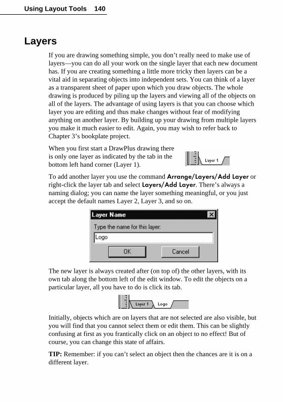
Using Layout Tools 140
LayersIf you are drawing something simple, you don’t really need to make use oflayers—you can do all your work on the single layer that each new documenthas. If you are creating something a little more tricky then layers can be avital aid in separating objects into independent sets. You can think of a layeras a transparent sheet of paper upon which you draw objects. The wholedrawing is produced by piling up the layers and viewing all of the objects onall of the layers. The advantage of using layers is that you can choose whichlayer you are editing and thus make changes without fear of modifyinganything on another layer. By building up your drawing from multiple layersyou make it much easier to edit. Again, you may wish to refer back toChapter 3’s bookplate project.
When you first start a DrawPlus drawing thereis only one layer as indicated by the tab in thebottom left hand corner (Layer 1).
To add another layer you use the command Arrange/Layers/Add Layer orright-click the layer tab and select Layers/Add Layer. There’s always anaming dialog; you can name the layer something meaningful, or you justaccept the default names Layer 2, Layer 3, and so on.
The new layer is always created after (on top of) the other layers, with itsown tab along the bottom left of the edit window. To edit the objects on aparticular layer, all you have to do is click its tab.
Initially, objects which are on layers that are not selected are also visible, butyou will find that you cannot select them or edit them. This can be slightlyconfusing at first as you frantically click on an object to no effect! But ofcourse, you can change this state of affairs.
TIP: Remember: if you can’t select an object then the chances are it is on adifferent layer.

Using Layout Tools 141
If you want to be able to select and edit objects irrespective of the layer theyoccupy, right-click any layer tab (or choose Arrange/Layers) and select Edit All Layers. To view only one layer at a time, right-click a layer tab (orchoose Arrange/Layers) and uncheck View All Layers.
When the drawing is put together from the objects on each of the layers, theyare drawn in the order in which the layers were added. Put another way: thelayers are drawn in the order of their tabs from left to right. For example, ifyou want a layer that is to act as a background to all the other layers, makesure it is the first layer.
If you select an object on a given layer you can move it to another layer usingthe Move To Layer/Move Forward One Layer and Move Back One Layer commands, which are in the Arrange/Layers menu. There’s also aMove Object to Layer... command that lets you specify the particular layerwhere the object should go.
If you need an overview of the layers that make up a drawing, then you needto call on the Layer Manager. The easiest way to get to the Layer Manageris to double-click any layer tab. You can also right-click a tab and chooseLayer Manager or use the Arrange/Layers/Layer Manager menucommand.
The Layer Manager allows you to add a new layer, rename an existing layer,delete an existing layer and alter the order of the layers by way of the Move Up and Move Down buttons. If you delete a layer all of the objects on it arelost! So if you want to keep any of them, move them to another layer first.

Using Layout Tools 142
In addition to modifying the layer structure of a drawing, you can also use theLayer Manager to select whether a given layer is visible by checking orunchecking its Visible box. The Printable box lets you select which layerswill be printed; non-printing layers are handy “for information only.” TheLocked check box can be used to freeze a layer and make it uneditable. IfView All Layers is unchecked, only the currently selected layer is visible.Checking that box plus Edit All Layers allows you to select any objectsimply by clicking it, regardless of which layer you’re on.
Even if you don’t need to make use of layers, some of the Wizards do. Forexample, the Studio’s Library tab includes Watermarks and Backdrops thatadd a “Paper” layer to your drawing that sits behind all the other layers.
PROJECT: The Map RevisitedIt’s time to return to Chapter 5’s sketch map, which we left at a very basicstage. We drew roads and a single symbol for a house made up of two filledshapes—a roof and walls. We left off by giving these two objects contrastingfills. Having reopened your document, select them both and click the Groupbutton to turn them into a single combined object.
The final house object can now be selected and sized and if you want morehouses it can simply be copied. For now though leave it on the pasteboard.
Adding a churchTo show just how useful graphics objects are, let’s add a church to the mapas a landmark. If at this point you are starting to work out how to draw achurch from scratch you’re not thinking hard enough about reusing objects tosave time!
To create a church from the house object all we have to do is make a copy ofthe house and then ungroup it using Ungroup. Once you’ve done this, youcan edit the roof separately from the body of the house. Select the roof, thensquash and stretch it by dragging on its handles until it looks like a steeple.Select and stretch the bottom shape of the building in the same way and thefinal result, after another grouping operation to make it a single object, is achurch symbol.
�

Using Layout Tools 143
Layers for different purposesBefore we move any of the building symbols off the pasteboard and onto thepage, let’s consider how layers might help in drawing a map that is suitablenot just for one purpose but for reuse. How often have you drawn a mapassuming that a visitor is coming from the North only to discover that theyhave decided to approach from the East? The roads stay the same but thelandmarks they will be aware of are different. Or you draw one map to showthe way to your house and realize that something almost the same wouldserve for visitors to your office—but without the quirky comments!
So let’s use the existing layer for the parts that don’t change: the roads,railways, rivers, and so on. We’ll add one layer for landmarks and haveanother layer for labels, comments, and other text items.
First rename Layer 1. The Layer Name dialog opens from the right-clickmenu but as we also want to add two more layers, the quickest route is todouble-click on the Layer 1 tab to display the Layer Manager. Click theRename button and name the first layer “Roads.” Click the Add button forthe new layers and give them meaningful names: “Landmarks” and “Labels.”

Using Layout Tools 144
When you return to the page notice that there are now extra tabs for the newlayers.
Now it’s time to place the symbols on the map, but they were originallydrawn on the first (Roads) layer. The solution is to select all of the symbolson the Roads layer that should be on the Landmarks layer and use thecommand Arrange/Layers/Move To Layer.
Now you can select the Landmarks layer and move the house and churchsymbols into place,, secure in the knowledge that you are not going to disturbthe road layout. Then you can proceed to the Labels layer to add text.
A compass pointYou can carry on adding details to your map for a long time, but onerefinement shows just how easy drawing can be with DrawPlus, if you thinkabout it in the right way. To help people know which way North is, it wouldbe a good idea to place a compass arrow on the Roads layer.

Using Layout Tools 145
If you are thinking about drawing the arrow at the correctangle and then drawing the cross at the center and so onyou are still thinking about drawing on paper! UsingDrawPlus you assemble the compass arrow more or lessautomatically.
First draw a long vertical line and select a suitable arrowhead for it. Then draw a short horizontal line and a circleusing the QuickEllipse tool. If you hold down the Shiftkey while drawing the lines it will be easy to make themperfectly vertical and horizontal. Holding down the Ctrl key while drawingthe QuickEllipse gives you a perfect circle. Don’t worry about trying to makethe parts of the compass arrow line up. Simply select them all as a temporarygroup and use the Align Items command to center them horizontally andvertically. The result is a perfect compass arrow which you then can makeinto a single group.
Finally add the “N” in the correct size and use Align Items to center it on thepoint of the arrow. Group all of the objects to make one single, compositecompass arrow and now rotate it to the correct angle.
You can carry on adding to your map until it is good enough to use. Don’tforget to save it because you are sure to need to use it and modify it in thefuture.

Special Effects

Special Effects 149
IntroductionWhat makes a design “good”? Usually it’s a combination of basic principles(composition, color balance, and such) plus an inspirational spark that setsone design apart from the others. Often that spark comes from appreciatingwhat others have achieved, or from trying a technique for the first time. TheDrawPlus Design Wizards offer some starting points and (we hope) someincentive to create original designs of your own. It’s also important that youknow as much as you can about all the tools at your disposal. Seeing how thetools work, and then trying them yourself, will literally open your eyes tonew possibilities—and spur your own creativity.
In this chapter we’ll spend some time looking at tools we may just havementioned in passing, explore some new ones, and offer some examples ofhow to “put it all together” for effects you might not have thought possible.
Text EffectsAlthough you might think of text as just being the mundane, informative partof your design, it often has a key role to play in setting the visual tone. Thebasic shapes of the letters are controlled by the typeface that you select. Atypeface is a family of fonts in different sizes and typestyles—bold, italic,etc. It’s important to understand font choices as a starting point, but withDrawPlus, you can achieve typographic results that go far beyond the limitsof particular fonts.
Font choicesYou can categorize typestyles in many ways: for example, as serif, sans-serif, and decorative. A serif font has short lines at the end of each longerline that makes up the letter. Serif fonts are generally regarded as thetraditional fonts where sans-serif fonts are the newcomers. Sans-serif fontslook modern, mechanical, and clean. Serif fonts look authoritative andtraditional—the original text book style! Often a sans-serif font and a seriffont are used in combination (as in this book), with a serif font for legiblebody text paired with a complementary sans-serif font for headings andemphasis.
Before computers, in the days when every font was equivalent to hundreds ofsmall lead blocks, it wasn’t easy to experiment. Using DrawPlus, selecting afont is easy and you can preview the large number of “decorative” or displayfonts which are often neither serif or sans-serif.

Special Effects 150
The most commonly used sans-serif font is Helvetica which is available asArial in Windows. The most-used serif font is Times Roman which youknow in Windows as as Times New Roman. The DrawPlus 6.0 Companionuses these two fonts. There is no “most common” decorative font; it’s up toyou to decide on your favorite!
Arial a sans-serif fontTimes New Roman a serif font
You can be fairly free in your choice of fonts when creating a drawing butthere are some points to remember.
Try to remember the following rules:
♦ Don’t use too many fonts. It makes a design look messy and difficult tounderstand.
♦ Make sure that important text is readable. Never sacrifice legibility fordesign.
♦ Choose fonts that work together. Look at your entire design and see ifany font looks as if it belongs to another drawing.
Arranging lettersOnce you have selected a font you also need to think about how best toarrange the text on the page. Most of the time you can let DrawPlus set thedistances between letters and words, but sometimes it is worth moving a pairof letters closer or further apart to create an effect. This is called kerning. Todo it in DrawPlus, you use the Node tool to adjust the letter positions byhand.
To make the job easier, hold down the Shift key after selecting a letter tomove. This constrains it to move only horizontally or vertically. If you wantto move a group of letters, select them one at a time with the Shift key helddown.
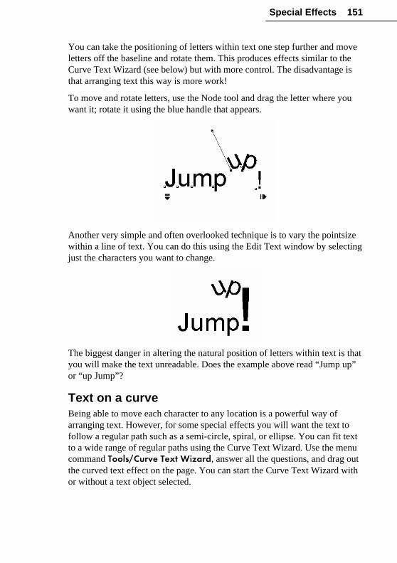
Special Effects 151
You can take the positioning of letters within text one step further and moveletters off the baseline and rotate them. This produces effects similar to theCurve Text Wizard (see below) but with more control. The disadvantage isthat arranging text this way is more work!
To move and rotate letters, use the Node tool and drag the letter where youwant it; rotate it using the blue handle that appears.
Another very simple and often overlooked technique is to vary the pointsizewithin a line of text. You can do this using the Edit Text window by selectingjust the characters you want to change.
The biggest danger in altering the natural position of letters within text is thatyou will make the text unreadable. Does the example above read “Jump up”or “up Jump”?
Text on a curveBeing able to move each character to any location is a powerful way ofarranging text. However, for some special effects you will want the text tofollow a regular path such as a semi-circle, spiral, or ellipse. You can fit textto a wide range of regular paths using the Curve Text Wizard. Use the menucommand Tools/Curve Text Wizard, answer all the questions, and drag outthe curved text effect on the page. You can start the Curve Text Wizard withor without a text object selected.

Special Effects 152
As an alternative to the Curve Text Wizard, you can fit the currently selectedtext object to a curve by clicking on the Curve Text flyout on the Standardtoolbar.
Using the flyout lets you quickly try out a range of different curves. And youcan still edit the curved text with the Text tool!
To straighten curved text, simply select the straight-line path in the CurveText Wizard or Curve Text flyout.

Special Effects 153
ShadowsAdding a drop shadow to an object can be done for a realistic lighting effect,or simply for stylistic value. Shadows are particularly effective with text.
Single-clicking the Shadow button on theStandard toolbar displays a flyout with a choiceof preset shadow effects.
Another way to apply a drop shadow is to choose the Shadow tool (onthe Drawing toolbar), then drag from the object. You can continue to clickand drag the shadow to adjust its position. To toggle between a simple and aslanted shadow, press Ctrl and begin dragging.
Double-clicking the flyout button or right-clicking the object and choosingShadow... opens the Edit Shadow dialog and here you have completecontrol over the appearance of the shadow added to an object.
There are three choices in the Type box. None is used to remove a shadow.

Special Effects 154
Simple is a standard drop shadow. You can change the values in the Offsetsand Scale boxes to deepen the shadow and determine the direction lightappears to be coming from.
A Slanted shadow has the effect of adding depth to the object itself, makingit appear three-dimensional. With the option selected you can also entervalues for the amount of slant.
The Blur control allows beautiful soft edge effects to be given to shadows.
You can see the effects of your current choices interactively in the sample atthe bottom right of the dialog box.
Filter EffectsFilter effects are creative manipulations—particularly well adapted to text—that you can apply to any object.
Inner Shadow Inner Glow Outer Glow
Inner Bevel Outer Bevel Emboss Pillow Emboss
♦ Inner Shadow adds a diffused shadow effect inside the edge an object.(For a drop shadow effect, use the Shadow flyout or tool as describedabove.)
♦ Inner and Outer Glow add a color border (stroke).
♦ Inner and Outer Bevel add a rounded-edge effect.
♦ Emboss and Pillow Emboss add a convex or concave rounded edge andshadow.

Special Effects 155
To try these out for size, choose Filter Effects... from either the Tools menuor the object’s right-click menu. Then use the dialog to select an effect fromthe list at left. If you check Automatic, you’ll see the object itself updateinstantly; or you can leave the box unchecked and click the Manual buttoneach time you want to refresh the display. Adjust the sliders or enter specificvalues to vary the effect (see online help for details on each control). You caneven combine multiple filter effects for unique results.
EnvelopesAn envelope distortion is one that you can apply to any object to change itsshape without having to edit its nodes. To understand how an envelopeaffects the shape of an object, imagine it drawn on a rectangular rubber sheetwhich is stretched to the outline of the selected envelope. As you mightexpect, this is a very powerful feature for special effects—and not only fortext.
The simplest way of applying an envelope distortion is to use the EnvelopeWizard. Select the object or group of objects you want to distort and chooseTools/Envelope Wizard. As the first step, the Wizard gives you the choiceof applying the distortion either to the currently selected object or to somenew text. The next step lets you browse through the possible envelope shapesand preview their effect.

Special Effects 156
Once you have selected the envelope you want to use and clicked Finish inthe final step, you will see the object distort to match the preview. The Nodetool is also automatically selected for you and you will see the objectsurrounded by the outline of the envelope selected. You can use the Nodetool to edit the outline by dragging the nodes. The only difference is that thereshaping changes the way the enclosed object looks.
Because you can edit the envelope so extensively, if there isn’t one to suityou in the Wizard, select the closest shape and edit it to be exactly what youwant.
An alternative to using the Envelope Wizard is to click the Envelopebutton on the Standard toolbar. This offers you a flyout with all of thestandard envelopes available.

Special Effects 157
3D Perspective
The Perspective flyout, like the Envelope flyout next door to it,produces an overall shape distortion. But while the Envelope effect stretchesthe object as if it were printed on a rubber sheet, Perspective gives you thevisual impression of a flat surface being tilted in space, with an exaggeratedfront/back size differential. Using the Node tool, you can achieve just aboutany freeform viewpoint, making this a versatile effect for both text andshapes. You can achieve a similar result using Shear and other tools—butonly with considerably more effort!
To begin, select an object and click the Perspective button onthe Standard toolbar, revealing the preset choices. Select theone closest to the effect you’re after. Note that the first choice(“No Perspective”) gives you the option of removing the effectlater, if you wish.
The effect is applied immediately and the Node tool isactivated, with a “3D” cursor over the selected objectand a special adjustment slider. Now you can drag the slider handle,
or drag the object freely in any direction and see it respond by tilting into allsorts of orientations. Use Undo if you’re not happy with a particularadjustment.
Roughening
The Roughen tool lets you selectively distort an object’s outline, for ajagged appearance. The effect lends cartoon-like flair to ordinary text...

Special Effects 158
...and it’s equally useful for customizing QuickShapes whenever an irregularappearance seems to suit the mood of the design.
Using the tool is simply a matter of selecting it from the Drawing toolbar anddragging up or down on a selected object. The more you drag, the rougherthe object’s outline becomes. Note that only the outline is affected and there’sno internal distortion—so if the object is using a bitmap fill, for example, thefill remains intact. Once applied, you can’t remove the Roughen effect, asyou can with many others, so use Undo immediately if you’re not satisfied.
Blends
The Blend tool on the Drawing toolbar enables you to “morph” anyshape into any other shape in a specified number of steps. If the two shapesare separated in space, each step creates an intermediate shape, a kind ofmorphing effect. The result is a group object.
If the starting objects are in the same place, the results can be especiallyinteresting. For example, draw a QuickStar and fill it with a solid fill. Thenduplicate the object, shrink it, and fill with a much contrasting color. Centerthe small star inside the large star (you may want to align their centers).

Special Effects 159
Now select the Blend tool and move the cursor over the larger star (the largerstar object highlights), click and drag the cursor so as it is over the smallerstar (this object highlights) and release the mouse button. A dialog asks youto enter the number of steps; try 10 or 15. The result is a unique union of thetwo original objects!
If the two objects you want to blend are quite close together, makingselection with the Blend tool difficult, you can begin by selecting them bothwith the Pointer tool, then using Tools/Blend to apply the effect.
Try the same effect with text for exciting results!
Chain LinesA chain (or chain line) is a decorative line incorporating one or moreindividual DrawPlus objects arrayed along its length—rather like a bordermotif, but with all the freeform adaptibility of a plain line. You can choosefrom the wide assortment of chain lines in the Studio’s Line tab gallery(encompassing all the line categories except “Plain”), edit their properties tosuit your needs, or create your own chains from scratch. Apply chains tolines, curves, QuickShapes, even filled shapes... anywhere you want toinstantly introduce repeating elements.

Special Effects 160
Applying a chain line from the Line tab is just like applying a plain line. Justselect the Line Type category and drag a thumbnail onto an object (or selectthe object first, then click the thumbnail). While the pre-supplied chains inthe gallery offer plenty of possibilities, it’s quite easy to create your own by“stringing together” one or more DrawPlus objects, adding one selection at atime to the chain. (Select the items to be added, then right-click the gallerythumbnail and choose Add Element.)
Other right-click options from the Line tab let you add a new chain to agallery, or delete an existing one. Online help (search “chains” in the Index)includes step-by-step instructions.
Standard Line tab formatting options like thickness, line style, and line enddo not apply to chain lines. Rather, there’s a whole separate dialog forcustomizing chains—either locally (after the chain has been applied to anobject) or in a Line tab gallery. To edit a chain, right-click either the localobject or the gallery thumbnail and choose Edit Chain....
On the dialog’s Options tab, drag the Global Scaling slider to adjust theoverall proportions of the chain’s elements with respect to the line or shape.You can fine-tune such properties as Scaling, Rotation, Spacing, Offset,and the Order of individual elements that comprise the chain. We’veincluded a few examples below. Again, online help provides completedetails.
◄ Original line
Chain applied; default settings ►
◄ Spacing uses smaller Gap
Rotation set to Follow Path (local line slope) ►

Special Effects 161
◄ 2 Dabs (overlaid elements),with a Rotation Incrementof 30º between elements
Order is By Direction:Note gray arrows appearwhere the line slopes up,
blue where it slopes down ►
The dialog’s Elements tab lets you rearrange the sequence of elements in achain. To shift an element, click to select it, then click the Shift Left or Shift Right button. To delete a selected element, click the Delete button.
Multiple Copies
The Transform WizardThe Transform Wizard lets you make multiple copies of one or moreselected objects, with a transformation applied to each successive copy in theseries. You can choose from predefined transforms, or specify the type oftransformation (rotation and/or scaling), the number of copies, and apositional offset between copies. It’s a quick way to generate elements for ananimation sequence involving rotation or directional changes (see the nextchapter).

Special Effects 162
To use the Transform Wizard select Tools/Transform Wizard. Try using theTransform Wizard with simple, single objects or objects with a clear fill. It’seasy to create amazing “spirograph” style effects.
To turn the Transform Wizard on or off, choose Options... from the Toolsmenu and click the Ease of Use tab, then check or uncheck Transform Wizard.
If the Wizard is off, Transform... will be available on the tools menu. Thisshows a single dialog that lets you set the transform options.
The Replicate WizardThe Replicate Wizard, as you may remember from Chapter 3, lets you fill agrid with identical copies of one or more selected objects. For example, youcan specify three columns and four rows, for twelve identical copies. Youalso have the option of letting DrawPlus determine the grid layout for you.The tool comes in handy for creating repetitive patterns or producing artworkfor label sheets.
Before you use the Replicate Wizard, size the object to be cloned and place itin a convenient starting position—usually the top-left of the page.
To use the Replicate Wizard select Tools/Transform Wizard.

Special Effects 163
If you ask the Replicate Wizard to position the objects for you (the default), itwill devise the most suitable grid. If you prefer, you can specify a layout gridin terms of column and rows. The only point to remember on the next page ofthe Wizard is that one object already exists. So if you want a total of 12objects you need to ask for 11.
To turn the Wizard on or off, choose Options... from the Tools menu andclick the Ease of Use tab, then check or uncheck Replicate Wizard.
If the Wizard is off, you’ll see the Replicate... command instead. This bringsup a single dialog that lets you specify the number of rows and columns, aswell as the X and Y spacing (horizontal and vertical gap) between objects.
ContouringThe Create Contour function lets you reproducea single object slightly larger or smaller than theoriginal, for perspective or shape effects. Forexample, you can quickly create outlines aroundtext.

Special Effects 164
In the illustration below, all the component objects have been detached fromthe completed drawing of a corkscrew. Notice how the artist achieved a 3Dlook for the handle and cork using both blending and contouring, by stackingprogressively smaller shapes, using differently colored fills graded from darkto light.
To make a larger or smaller copy of an object, select the object you want toreproduce, then choose Create Contour... from the Tools menu. Use thedialog to specify the degree of difference and position of the new object withrespect to the original, and click OK. A reduced copy appears in front of theoriginal object; an enlarged copy appears behind it. The new object alwayshas a black line and white fill for visibility, but it’s selected so you can applya custom line and fill right away.
Combining ObjectsHow can you produce a shape with a hole init? One way would be to draw the hole shapeinside the object and then fill it with thebackground color. For example, if you drawtwo circles, one within the other, and fill theinner one with white, the result looksconvincing.
But as soon as you place the object overanother one you quickly see that it isn’t asconvincing as you thought because you can’tsee through the hole!

Special Effects 165
But why waste effort thinking about the problem, when DrawPlus includesall the tools you’ll need to carve new shapes out of old shapes—theCombine, Crop, Add, Subtract, and Intersect buttons on the Standardtoolbar!
Original Combine Crop Add Subtract Intersect
Combine and Crop work a bit differently from the other three, which aregrouped as “Join” commands on the Arrange menu. It’s worth keeping thedistinctions in mind:
� With Combine and Crop, you’re creating a temporary compositeobject where two or more component objects used to overlap. Thiscombination, like a group, can be broken apart later.
� With the Join commands, you actually produce a permanent newobject out of any two selected objects. The action can’t be reversed,except by using the Undo command.
Now let’s see how the commands actually work. In all cases, you first haveto select the objects you want to combine or join, then click the appropriatebutton.
Returning to our “hole” problem, if the only goal is to create a doughnut(torus) shape, then either Combine or Subtract would do the job. Just place asmall circle (with no line) over the large circle, select them both, and clickeither button. Problem solved! (For a symmetrical shape, you could simplyhave used a QuickDonut in the first place... but with these tools, the hole canbe off-center. It’s your call.)
Which function you choose may depend onwhether you want to restore the componentobjects later (in that case, choose Combine).But each tool has its advantages.
Combine merges two or more objects intoa composite object, with a clear “hole” wheretheir filled regions overlap. The composite takes the line and fill of thebottom object. If the selection includes a number of objects and some of themcan’t be combined (groups, open lines or enveloped objects, for example),Combine will still handle any valid objects within the selection.

Special Effects 166
Crop also creates a composite from two or more overlapping objects,using the back object as a “cookie cutter” and retaining everything visiblewithin that outline. You may find it more convenient to bring the templateobject to the front while adjusting its shape. Then use Send to Back to placeit behind the rest of the objects, marquee-select around the whole stack, andcrop.
To Break Apart a combined object or Uncrop a cropped object, simply clickeither button again.
Unlike Combine and Crop, the Join functions are only enabled if exactly twovalid objects are selected. But a Joined object can be edited with the Nodetool, while a Combined or Cropped object cannot. (For the completerundown, consult online help.)
Join/Add creates one new object that’s the sum of any two selectedobjects, whether or not they overlap. With all the Join commands, the newobject derives its line and fill from the back object.
Join/Subtract is useful as a quick way of truncating shapes andpictures. For example, you can use a QuickBox as a straight-edge “eraser.”Just place the box over the edge of the object you want to trim, select bothobjects, and click Subtract. The result is a single new shape.
Another trick is to slightly offset two pieces of text, then use the Subtract toolto create shapes that can be used for highlight and shadow effects overexisting text.
Join/Intersect, like Subtract, requires overlapping objects—it retainsthe overlap and discards the rest.
Using just QuickShapes and the Join tools, you can create a tremendousvariety of special shapes. You may never have to use the Freehand toolagain!

Special Effects 167
Studio Library ElementsWe began this chapter remarking that Design Wizards were a good startingpoint, both for graphic objects and for inspiration. And we’ve covered anumber of other Wizards here that facilitate special effects. So it’s onlyfitting that we conclude by mentioning yet another category of DrawPluswizardry—the art, text, and shape elements you’ll find listed on the Studio’sLibrary tab. If you tried the bookplate project in Chapter 3, you’ve alreadyseen how easy it is to add and edit Library tab elements.
Actually, you’ll have more fun discovering these resources by yourself. Allthe categories are right there in plain view, with thumbnails ready to drag anddrop onto your page for serious design work, experimentation, or a bit ofboth. They’re especially well suited to Web page construction.
Shape Art includes an assortment of prebuilt figures that can be usedseparately or in combination with other objects. Many are just waiting fortext to be placed over them...
Text Art lets you enter your own text and see it rendered in any of a varietyof ways, over different backgrounds and with intriguing color and shadingeffects.

Special Effects 168
Banners and Stamps round out the collection will an all-purpose assortmentof greetings, messages, logos, and fun stuff.
Try “deconstructing” some Wizard elements to see how they’re put together.And then go off and create your own masterpieces!

Web Graphics

Web Graphics 171
IntroductionDrawPlus has a lot to offer if you’re producing either static or animatedgraphics for Web pages. It’s hard to overstate the advantages of scalablevector graphics, which let you work at any level of detail and revise anyportion of the image. On top of that, DrawPlus adds export optimization andbrowser preview capabilities, so you’re assured of getting the results youwant while minimizing file sizes. This chapter explains how to createanimated GIFs, and how to add hyperlinking and onscreen interactivity tothings like Web buttons and menus.
Animation BasicsThe term “animation” can cover everything from flip-books to Disneymovies. We’ll focus on what DrawPlus does best: create animated GIFsspecifically for Web pages. You’ll quickly see that using DrawPlus, you canproduce results that equal or surpass anything you’re likely to see on the Web.
Creating Web animation with DrawPlus 6.0 is easy—there’s no special skillrequired. Of course, the more comfortable you are with the whole range ofDrawPlus tools and effects, the further you can go. If you’re just starting outwith DrawPlus, you may wish to take a look at the first four QuickTours tofamiliarize yourself with basic terms and concepts. (You can safely skipQuickTour 5, “Creating Animations”—this chapter will provide more depthplus the advantage of hands-on practice.)
Bear in mind that DrawPlus isn’t an animation editor as such. You canpreview your work and export it to an animation file format (GIF) but youcan’t actually import or play back content in that format. DrawPlus is apowerful vector graphics program, and the control that gives you over objectsand special effects makes it ideal for generating animated GIFs. Chances areyou won’t need a specialized animation editor. However, when it comes toactually using your animations on Web pages, you’ll need a program capableof creating Web pages, such as Serif’s PagePlus.
What is animation? Like movies and TV, it’s a way of creating the illusion ofmotion by displaying a series of still pictures, rapidly enough to fool theeye—or more accurately, the brain. Professional animators have developed awhole arsenal of techniques for character animation—rendering human (andanimal) movement in a convincing way. We can leave most of this to theexperts. Web graphics, as a rule, are small (mainly to keep file size to aminimum) and most often involve shape and color transformations ratherthan realistic portrayals. So let’s get started.

172 Web Graphics
PROJECT: Spinning a spiralWe’ll want to begin with a blank slate, so start DrawPlus (or chooseFile/New if it’s already running). Select Create an Animation from theStartup Wizard, scroll down in the “page size” list and select “Logo 1,” thenclick Finish.
(If by chance you’ve turned off the Startup Wizard, choose File/New andselect any page size. When the new document opens, choose Convert to Animation from the File menu.)
A new document window opens, with DrawPlus in Animation Mode. Ifyou’ve already used DrawPlus for other work, you may notice a few subtledifferences: a yellow (instead of white) pasteboard, a tab at the lower leftlabeled “Frame 1” (instead of “Layer 1”), and the Animation toolbar, justbelow the Standard toolbar.
The “blank slate” we’ve started with is actually the first frame of ouranimation, as its label signifies.
When working with animations, it is often better to use pixels as the rulerunits for positioning and sizing objects as this gives a clear impression of thesize and quality likely to be produced when the animation is used on a Website. Select Tools/Options… and use the Layout tab to change your rulerunits to pixels.
Note that you will want to change your ruler units back to a different unitwhen working on different drawings – use the same dialog to switch to adifferent ruler unit whenever required.
What we’ll do now is create a series of six frames, each with a slightlydifferent image, and then play them back to preview an animation.
Click the QuickShape button on the left (Drawing) toolbar.
Select the QuickSpiral—the third tool down on the left of the flyout.Holding down the Ctrl key, click and drag on the page to draw out a spiralabout 150 pixels on the rulers. (The Ctrl key constrains the shape to be round,not oval.) Leave the spiral’s control handles set as in the illustration.
�

Web Graphics 173
Now let’s make the spiral spin. Imagine the figure as a pinwheel that youcould turn by hand, pausing at regular intervals to record its new position asanother picture. Eventually, it would get back to its starting point, and if weplayed back the pictures in succession we’d get the illusion of rotation. If wecreated a loop, each time jumping back to the first frame after playing thelast, we’d get the illusion of continuous rotation. So let’s do just that.
Click the Clone Frame button on the Animation toolbar. This copies thecontents of the current frame (Frame 1) to the end of the frame sequence, asFrame 2 in this case. (Be sure to click the correct button; if your new frame isblank, you clicked the New Frame button by mistake, select Undo and tryagain.
Now choose the Rotate tool from the Drawing toolbar and click on thespiral to select it. Be careful not to drag when you click; we don’t want tomove the spiral. (If you accidentally do move it, select undo.) You’ll see thespiral’s rotation handles. Holding down the Shift key to constrain the rotation,click on the top right corner handle and drag clockwise for two 15º increments,or a total of 30º.
You can check that the adjustment is correct by clicking the Frame 1 tab tosee the starting spiral, then the Frame 2 tab. You should notice the beginningsof the rotation effect by toggling between the two frames.
When flipping between adjacent frames like this, you may find it moreconvenient to click the Previous and Next buttons on the Animation toolbar.
Previous Next
Make sure you’re on Frame 2, then click the Clone Frame button again. Thistime, Frame 3 appears. As before, select the spiral object carefully with theRotate tool and Shift-drag to rotate it through another 30º. The figure onFrame 3 is now rotated 60º from its starting position. Again, toggle betweenFrames 2 and 3 to make sure the spiral’s center hasn’t shifted.

174 Web Graphics
Repeat this process three more times, 30º at a time, to create Frame 4 (90ºfrom the starting position), Frame 5 (120º), and Frame 6 (150º). Since thespiral has two “tails,” once it gets halfway around it will be right back whereit started, as far as the eye can tell. So we don’t need to generate a 180ºview—in fact, we’re done!
Previewing the animation
Click the Preview Animation button on the Animation toolbar. Theanimation loads into the Preview window and begins playing at its actual sizeand speed. Notice that you see only the drawn portion of the animation (thespiral)—any extra surrounding white space is cropped away.
You can use the control buttons (Play, Stop, Back, and Forward) to reviewindividual frames. For example, if you notice that the rotation seems a biteccentric, you can step through the frames to locate one or more spirals thatmay not have been rotated correctly.
If you want to preview the animation in your Web browser, choose Preview in Browser from the File menu. This actually exports a temporary copy ofthe animation, using the current export settings (see below) and displays it inyour Web browser. You can leave the browser open and DrawPlus will findit again next time you issue the command.
Saving the DrawPlus fileDrawPlus saves animation documents in the proprietary .DPA format(Drawings are saved as .DPPs). Once you’ve got the spiral spinningsmoothly, choose File/Save... and congratulate yourself. You’re now ananimator!
Exporting animations
Once you’ve previewed the animation and made necessary any last-minute changes, click the Export Animation button on the Animationtoolbar. The Export Optimizer appears. If you’re just testing export at themoment, you don’t need to make any changes—but here’s a summary of theoptions for future reference.

Web Graphics 175
The Animated GIF format is preselected on the Format tab. The Settings tablets you scale the animation to any size as required. Leave the dpi setting at96 for standard screen resolution. If you require your animation to look at itsbest on 256 color displays you should use the Web-safe palette. This usesonly colors reproducible in the 216-color palette used by Web browsers.With most people using hi-color or true color displays, the Optimizedpalette affords greater display quality, allowing the DrawPlus export filter todetermine the best colors to use.
Check Transparent to turn unfilled regions of your graphic into transparentregions in the GIF so any Web page background will show through, andInterlaced to have the graphic appear progressively (line by line) in abrowser. Keep Anti-aliased checked to retain the smooth appearance of yourDrawPlus graphic, which will be anti-aliased to the background color(s)around its edges when it’s exported; uncheck for a sharp edge. For full detailson GIF export options, see this chapter’s later section on “OptimizingGraphics.”
On the Animation tab, which only appears in Animation Mode, you canpreview single frames or run the animation sequence, and make some finalplayback adjustments to the animation properties.
If certain frames seem to go by too quickly or slowly, you can select anyframe and enter a value greater than 0 (milliseconds) in the Duration box.The initial value matches the global duration setting (to be discussed a bitlater) and any new value you enter overrides the global setting, just for thatparticular frame.
If you want the sequence to play through only once and end byredisplaying the first frame, click the Fixed Loop button and type “1” in thebox. Enter a higher value to repeat the sequence a fixed number of times.
Click the Endless Loop button to have the sequence repeat indefinitely.
When all the settings are correct, click the Export button (or Close to simplyrecord the settings if you plan to preview in a browser first). Provide a filename and folder location, and click Save. You needn’t worry if you haveextra white space around your image. Any unused border area will becropped automatically, just as you saw in the Preview window.
More on Animation modeBefore we move on to other animation projects, here are a few other basicthings to know about working in Animation mode.

176 Web Graphics
You can convert an existing drawing to an animation by choosing Convert to Animation from the File menu. Note that once your work has been convertedto animation, it cannot be converted directly back to a drawing—so be sure tosave the drawing if you’ll need to use it again. With the exception ofdrawings that have a “paper layer,” discussed later, all layers in your drawingwill be combined into a single frame of animation.
To create a new blank frame rather than a clone of the current frame,click the New Frame button on the Animation toolbar. The new frameappears as the last frame in the series.
To delete the current frame, click the Delete Frame button.
As an alternative, you can right-click on a frame tab and choose New Frame, Clone Frame, or Delete Frame.
QuickShape AnimationBesides the spiral, the QuickShape flyout offers dozens of shapes, each withits own variations. The ease with which you can alter QuickShapes (using theNode tool) makes them ideal starting points for geometric animation effects,whether used singly or in combination with text or other elements.

Web Graphics 177
You can use the same basic approach we followed to create the spiralanimation with any QuickShape. First experiment with the possiblevariations: dragging the handles provides an instant preview of manypossible animation effects. Create a frame sequence by cloning frames andadjusting the object as you go. Of course, you can vary the size and positionof the QuickShape, too.
A QuickWave becomes a flexible spring...
A QuickFlash becomes an explosion...
And a QuickDonut (with a white circle for an eye) becomes a hungry sprite.
Fooling the Eye: Animation TechniquesTake a moment to examine one of the Sample animations included withDrawPlus 6.0. Choose File/New and select the View Samples option fromthe Startup Wizard menu. From the samples list, choose “EYE.DPA” (not the.DPP file of the same name). You can preview the animation—an eyeblinking—right in the dialog. Go ahead and open the file.
We won’t analyze how the image was developed, although it’s a fineexample of fills, blending, and other DrawPlus techniques. The point tonotice is that there are only two frames in the whole document, one where theeye is open and the other where it’s shut. If you were to inspect the timings ofthe two frames, you’d find the “open eye” frame lasts a full 1.25 seconds,while the “shut eye” frame lasts only a fifth of a second. Although we neveractually see anything in between, apparently our “mind’s eye” supplies themissing motion. It’s a convincing illusion.
�

178 Web Graphics
You don’t have to be an expert on human perception to create skillfulanimation, but your animation will improve if you keep an open mind aboutwhat makes a given effect succeed or fail. In small-scale animations, it’srarely a question of how detailed or realistic the image is. More often it boilsdown to careful positioning, sequencing, and timing, as well as playing withthe laws of physics to reinforce specific actions. And the human mind isalways part of the equation.
In this section, we’ll try some more mini-projects, explore the rest of theDrawPlus animation tools, and touch on some tricks of the trade.
Follow the bouncing ballReady for another simple exercise? Open a new animation document, thistime using the Small Logo 1 page size.
Begin on Frame 1 by drawing a QuickEllipse circle, holding down the Ctrl keyto constrain its proportions. Adjust it so it’s 20 pixels across.To measure the object precisely, select it andthen double-click the ruler intersection. This willmove the ruler origin to the selected object, andyou can read its dimensions as the white portionalong each ruler. When you’ve adjusted thecircle’s size by dragging its lower right handle,double-click the intersection again to reset therulers.
Position the circle on the left side of the frame. We’re going to create threemore frames for a “bouncing ball” effect, and examine how frame timingaffects the result.
DrawPlus supports onion skinning, a standard animation technique derivedfrom cell animation, where transparent sheets enable the artist to see throughto preceding frame(s). It’s useful for enabling precise registration andcontrolling object movement from frame to frame. You can turn the featureon or off (the default is off) as needed, and set the number of previous framesthat will be visible (normally one).
�

Web Graphics 179
Turn onion skinning on now by right-clicking the frame tab and checkingOnion Skinning on the menu. Now clone the frame. In Frame 2, click toselect the ball object, then hold down the Shift key and drag it horizontally tothe middle of the frame. As you drag the object, you’ll see another objectbehind it that remains on the left of the frame. That’s Frame 1’s objectshowing through to Frame 2. With onion skinning on, it’s easy to make sureboth objects are still aligned with the same vertical position. (If the new oneshifted, delete the frame and try again.)
Then clone Frame 2 and Shift-drag the ball again, this time over to the rightside of the frame. Again, you can check its position with respect to the centerobject.
Finally, return to Frame 2 and clone it. The cloned frame appears as Frame 4,to complete the four-frame sequence.
Now click the Preview Animation button and check out the results. Youmay be impressed that the ball moves—but it’s not (yet) a very goodanimation. Chances are that as you watch the preview, you’ll quite oftennotice two of the balls appearing visible at the same time, hardly aconvincing illusion of motion. We can do better.
Timing is everything
Click the Animation Properties button on the Animation toolbar. In thedialog, you’ll see that the Duration setting is currently 10/100 sec, whichworks out to 10 frames per second. This is the default frame rate, and if thebox next to the timing is checked, it means that the rate applies globally to allthe frames: each frame appears onscreen for exactly 10/100 of a second.Let’s experiment by varying the timing.
Try a duration value of 5/100, click OK, then preview the animation again.This time, at 20 frames per second, it’s even worse—now all three dotsappear nearly simultaneously. At this setting, the brain just isn’t able toprocess the frames separately.

180 Web Graphics
Return to the Animation Properties dialog and try 20/100 this time, thenpreview again. Well, at least at 5 frames per second the “dots” have turnedinto one “ball” that appears to move sideways. But the motion has a sticky,jerky quality. If you try a higher frame duration, the separate jumps are onlyaccentuated.
What’s wrong with our sequence is that we don’t have enough in-betweenframes to create the impression of smooth motion. There should be someoverlap between the ball objects from frame to frame, so the viewer’s mindwill “fuse” the position changes instead of perceiving them as jumps.
We’ll need to add four intermediate frames: two as the ball moves from leftto right, and two more as it returns from right to left. Start by cloning any oneof the frames, which will produce a new last frame, Frame 5. Then repeat thecloning three more times, each time from the last frame. Now Frames 5, 6, 7,and 8 exist, but they’re out of order and the objects need positioning on eachone.
As noted earlier, you can override the global duration setting for individualframes using the Export Optimizer’s Animation tab. In passing, notice thatthe Animation Properties dialog duplicates another property that’s settable inthe Export Optimizer: whether the sequence will loop continuously (thedefault) or repeat a certain number of times and then stop.
Using the Frame ManagerFirst let’s locate the new frames properly in the sequence. Right-click anyframe tab and choose Frame Manager. (You can also double-click a frametab.) The Frame Manager dialog, comparable to the Layer Manager inDrawing Mode, lets you view the whole sequence of frames as a scrolling listand reorder the sequence if you wish. (Notice that you can also add or deleteframes, set onion skinning options, and access individual frame properties,which we’ll discuss shortly.)
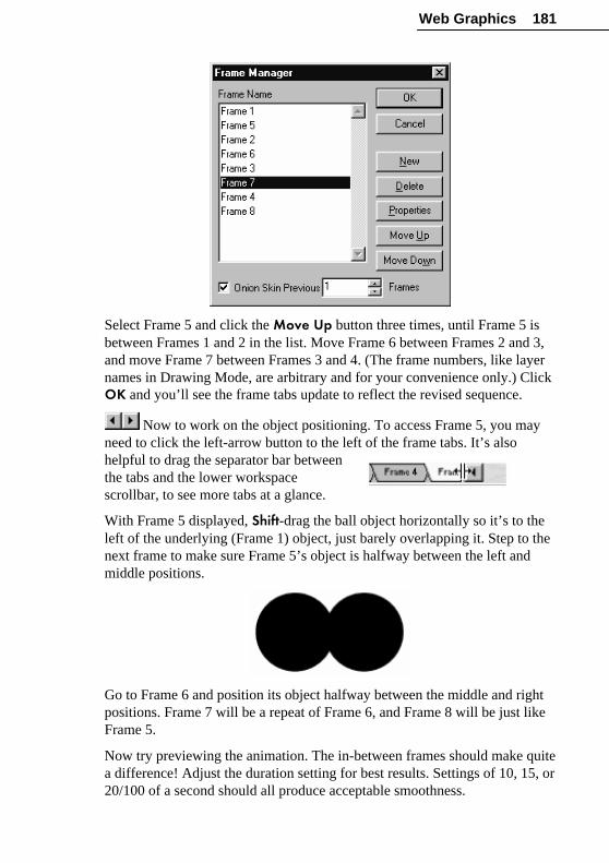
Web Graphics 181
Select Frame 5 and click the Move Up button three times, until Frame 5 isbetween Frames 1 and 2 in the list. Move Frame 6 between Frames 2 and 3,and move Frame 7 between Frames 3 and 4. (The frame numbers, like layernames in Drawing Mode, are arbitrary and for your convenience only.) ClickOK and you’ll see the frame tabs update to reflect the revised sequence.
Now to work on the object positioning. To access Frame 5, you mayneed to click the left-arrow button to the left of the frame tabs. It’s alsohelpful to drag the separator bar betweenthe tabs and the lower workspacescrollbar, to see more tabs at a glance.
With Frame 5 displayed, Shift-drag the ball object horizontally so it’s to theleft of the underlying (Frame 1) object, just barely overlapping it. Step to thenext frame to make sure Frame 5’s object is halfway between the left andmiddle positions.
Go to Frame 6 and position its object halfway between the middle and rightpositions. Frame 7 will be a repeat of Frame 6, and Frame 8 will be just likeFrame 5.
Now try previewing the animation. The in-between frames should make quitea difference! Adjust the duration setting for best results. Settings of 10, 15, or20/100 of a second should all produce acceptable smoothness.

182 Web Graphics
In general, the right amount of in-betweening and the optimal frame timingwill depend on how far your objects need to travel, and how fast you wantthem to get there.
A better bounceWe’ve got a moving dot now—but is it a ball bouncing? Not quite yet. Whena ball hits a wall, it doesn’t just change direction. A collision happens. Theball squashes and unsquashes, and animation can exaggerate this otherwisesubtle distortion to add visual interest.
It’s easy enough to achieve. On the two frames where the ball reaches the endof its travel—Frames 1 and 3, assuming the original numbers are stillintact—we need to resize the objects a bit. On each frame, select the objectand drag a side handle inward to squash the ball. Since the ball will lookstrange if it just gets narrower (where did its volume go?), don’t forget tostretch it out slightly, too: drag the upper middle handle up slightly, and thelower middle handle down the same amount. Keep the object’s center fixed.
Now play back the results, and see the difference. Here’s something that aviewer might recognize and respond to. You can’t see the “wall,” but the ballhas to be hitting something, right?
One more adjustment may make a difference. Select Frame 1 and clickthe Frame Properties button on the Animation toolbar. (Notice in passingthat you could change the frame’s name here, if you wanted to.) The durationsetting shown in the dialog matches the global setting you’re using for thesequence as a whole. Try increasing it slightly (remember, a small changecan make a significant difference). If your global setting is .15 second, tryupping that on Frame 1 to .20 or .25. Do the same for Frame 3. The point isthat when the ball hits the wall, it takes time to stop, squash, and unsquashbefore rebounding. A subtle increase in duration on these “contact” frameshelps make the collision, represented as it is by only one frame, seem thatmuch more believable.

Web Graphics 183
Of course, there’s nothing especially believable about a ball that caromsendlessly between two walls... but knowing when to exaggerate physicalrealities to make a point, and when to ignore them completely, is part of theskill (and fun) of animation. Anything that gets your point across with moreimpact and less confusion is worth trying.
Other Animation Techniques
Text animationSo far we’ve dealt exclusively with QuickShape objects, but the same basicprinciples of positioning and timing apply to any object you want to animate,including text. As you may know from working with text in Chapters 6 and9, DrawPlus gives you a wide choice of ways to vary text, ranging fromsimple size or fill changes to more complex effects like envelope distortionsor blends. As with QuickShapes, any ways that you can vary an object’sappearance can be put to good use in animation.
If you’ve got the DrawPlus 6.0 Design CD, you’ll find a range of instructiveexamples of text animation among the Design Wizards. These let you enteryour own text, then deliver a ready-made animation. Take a look at the Text Effects category, or use these brief descriptions as inspiration:
♦ In the Effects subcategory, “Effects 01” varies the extend of transparencyover the text to produce a soft-edge wipe transition.
♦ “Effects 02” rotates the text around its center (just like the spiral youcreated) through 360º, while varying its size.
♦ In the Text Scenes subcategory, which adds backgrounds behind thetext, “Falling” produces a flip effect by vertically stretching andcompressing the text with respect to a central axis.
♦ “Space” propels the text through the cosmos by rapidly reducing it as itmoves toward a vanishing point.
♦ Examples in the Distorted category employ curved text sequences.
Background framesUsing the Frame Properties dialog, you can designate any frame as abackground frame, which will remain visiblewhile the following frames animate “over” it.

184 Web Graphics
Typically, this would be the first frame in your sequence—for example, aclock face that remained static while hands (on the following frames)revolved around the dial. You might want to try adding a background frameto the “bouncing ball” animation, with a simple rectangle that the ball canbounce around in. A background frame remains visible until superseded byanother frame with the Background attribute.
You can use a background frame as a positioning aid while you’re creatingan animation and then delete it before exporting. For example, suppose youwanted to show a frog jumping back and forth between two lily pads. To beconvincing, the jump would need to traverse an arc—that is, slowing downslightly while nearing the high point, then accelerating a bit on the downwardside. You could mark the path with a series of objects on Frame 1:
Then, with Frame 1 designated as a background frame, you’d have a visualguide to help you place the “frog” in the correct positions, shown by the dots,on the following frames. You can delete Frame 1 later.
If you create a backdrop, watermark, or full-page border in Drawing Mode(for example, by running the Backdrop Wizard, Watermark Wizard, orBorder Wizard), the resulting object getsplaced on a special bottom layer called thePaper layer.
If you convert a drawing with a Paper layer to animation, you’ll find youhave two frames rather than the usual one to start with. The first frame willbe named “Paper” and will have the Background attribute, on the assumptionyou’re going to want it visible behind the other frames. Likewise, if you useone of these three Wizards in an animation, the result will automatically goonto a new first frame.
Overlay framesThe Frame Properties dialog also lets you designate a frame as an overlayframe whose non-drawn or blank portions become “transparent,” so thecontents of the preceding frame show through. The effect is rather likehaving onion skinning turned on, except that the overlay property carries

Web Graphics 185
over to the final animation. The main advantage is saving you the time ofhaving to copy or redraw objects in a series where each frame buildscumulatively on previous frames.
For example, you could show a series of footprints being laid down, startingwith the first footprint in Frame 1, the second in Frame 2, and so on. Usingoverlay frames, since all the footprints would remain visible, you wouldn’thave to place more than one object in each frame. (You can actually see thisanimation in QuickTour 5.)
Using frame edgesSuppose you want a collection of “bubbles” to appear to float out of a frame.The trick is to use the edge of the page (where it meets the pasteboard) asyour frame, since any objects that extend beyond the page will be croppedwhen the animation is exported (although you’ll still see them in the Previewwindow).
This is one case where it’s important to set the page to the correctproportions. (Size matters less, as you can always resize on export.)
Since non-drawn or blank space that’s not used in any frame will be croppedout of the exported image, make sure at least one of the bubble objectstouches each page edge at some point. This will preserve the frameproportions you’ve set (see left, below.)
To make bubbles appear to float out of the top of the frame, simply movethem so they overlap the upper page edge. The result, when cropped onexport, will be as shown on the right.

186 Web Graphics
You can use this overframing technique to bring objects in or out of theframe in any direction. The object makes a more convincing entrance (orexit) if it’s shown as a partial object at the point of transition in (or out) of theframe.
For example, the “Neon 02” in Text Effects animation category of the DesignWizards (on the DrawPlus 6.0 Design CD) uses five frames with two textobjects to produce a marquee effect. The two objects are jogged further to theright in each frame. In the output animation, we don’t see the letters outsidethe frame. The text simply appears from the left, marches across, anddisappears on the right.
Imagine...What’s next is entirely up to you. With DrawPlus 6.0 the learning andinventing never has to stop. So explore, experiment, and most of all—havefun! To help spark your imagination, here are some additional ideas for yourown animations...
DrawPlus SamplesTake a few moments to explore the inspired animations in the Samplesgallery (choose View Samples from the Startup Wizard menu). These arebased on the sample drawings with the same names. We’ve already looked atthe “Eye.” Some of our other favorites are:
♦ Blow Bulb: An exploding light bulb, with fragments flying in alldirections.
♦ Figure: An artist’s mannequin attempts a grand jeté—with direconsequences.
♦ Lamp: A mesmeric ’60’s flashback.

Web Graphics 187
Perception effectsGrab a book on optical illusions, or explore the World Wide Web forperception demonstrations. Sometimes quite eye-catching effects are possiblewith very simple combinations of lines and shapes. The spiral we createdearlier is a good example. Try these others:
♦ The Waterfall Illusion: A series of alternating stripes, moving in onedirection through a frame, creates a convincing impression of motion.Use overframing with partial stripes on entering and exiting the frame, toaccentuate the motion effect.
♦ The Barber Pole Illusion: A variation on the above, using diagonalstripes moving up or down, creates the effect of a rotating pole. Tryusing more of an S-shape to suggest a convex pole. Turned sideways, itbecomes a twisting screw or worm gear.
Character animationAs we’ve noted, the art of character animation is somewhat beyond the scopeof this chapter. But by using clipart and applying the basic principles, youcan get amusing and effective cartoon-like results. For example, loopingthese two frames creates a “walking” motion:

188 Web Graphics
Remember to apply the concepts of stretching and squashing, overlappingframes for smooth movement, arc motion, and timing. Here are some othertips to keep in mind:
♦ Anticipation: You can set up a major action with a minor “get ready, getset” action. For example, before a frog leaps up into the air, it couldsquat down a bit. Subtle preparatory gestures like this add interestwithout adding a lot of extra frames.
♦ Backdrop: Let background frames serve as a “stage” for your action.You can unlock and ungroup the Studio’s Backdrop Wizards and use anyof their parts in your own animations.
♦ Exaggeration: In cartoons, virtually anything goes. Wild facialexpressions, elastic arm and hand movements, and so on—just as long asthe basic timing works.
♦ Simplification: Don’t overdraw—take your cue from establishedcartoon conventions. There’s probably a good reason why our favoritecartoon animals all seem to have only three fingers and a thumb!
SimulationsRealistic animations have a definite place in presentations and instructionalmaterials. Whether you’re demonstrating the beating of a heart, cog wheelsturning, changes in a stock price, a route to follow on a map, or principles ofbasic physics, you can combine animated GIFs with HTML-based pages todeliver your informational message effectively.
♦ Consider using bitmaps as background frames and animating over them.
♦ Rather than trying to show too much or make too many points in oneanimation, break complex processes down into separate GIFs so eachstage is conveyed clearly.
♦ Except for essential labels, place explanatory text and titles outside theanimation to conserve file size.
♦ Scale file sizes to the delivery platform. If your HTML-basedpresentation will be played back from a hard disk rather than over anetwork or the World Wide Web (lucky you), you don’t have to worryso much about slow page-load times.

Web Graphics 189
Web resourcesFinally, take a look around at how animated GIFs are actually being used onWeb pages, and explore the dozens of animated GIF archives available. WithDrawPlus 6.0, your results can measure up to—or surpass—most of what’sout there. Try emulating effects you like, and soon you’ll have built up anarchive of your own work!
Image SlicingWith image slicing, a graphic is carved up into smaller graphics—each ofwhich can have its own link, like any Web graphic—and DrawPlus saves thesections as separate files when you export the image. The process alsooutputs HTML tags describing a table containing the separate image files, sothat a Web browser can reassemble them seamlessly. The result appears as asingle larger graphic, but with different regions linked to different targets.
The Image Slice tool lets you subdivide the page into separate sectionswhich can be exported using the .GIF or .JPG format. For each rectangularslice object you draw, you can specify alternate text, URL links, and/orJavaScript rollover code. DrawPlus intelligently carves the page area intoadditional sections as needed, based on the slice objects you’ve specified.
Interactivity aside, image slicing can be a way of delivering a Web pagemore effectively. Say you’ve got a fairly large graphic that would take fouror five seconds to load under standard conditions. Consider slicing it so thatthe image will assemble progressively on the page as each piece arrives. Forthe user, the page will seem to be loading faster.
PROJECT: Slicing a navbarLet’s run through the steps involved in creating a simple navigation bargraphic with separate slice regions. By all means, try it yourself—we’llreturn to this example when we look at rollovers later in the chapter.
Start a new document in Drawing Mode and (since we’re working for thescreen) use the Layout tab of Tools/Options... to set the ruler units to pixels.
Working at 100% zoom, begin by drawing a long QuickBox and giving it asolid, middle-tone fill. This one is about 50 pixels by 400 pixels:
�

190 Web Graphics
Now create a text object using the word “Home”. Scale it to about 26pt,position it neatly over the left end of the background rectangle, and choose asuitable font and complementary fill color.
Duplicate the text object three times using Ctrl-drag. The cloned objects willhave the same text and fill. Double-click each in turn and change their text tosay “Updates”, “Products”, and “Links”, then drag them into place as shownbelow. (Perhaps use Arrange/Align Items... to get them exactly in line.)
Save the drawing at this point.
Now let’s proceed to create the image slices. Right-click the “Home” textobject and choose Insert Slice Object. (If nothing changes on the screen, youneed to click the Show/Hide Web Objects button on the HintLine toolbarto turn on the display.) With Web objects displayed, your entire page—andthe navbar, viewed close-up—will look something like this (without thenumbers):
The blue-shaded rectangle (1) fitted to the “Home” text object is called aslice object, and it’s a special object that can be given text, link or rolloverproperties. The other rectangles (2 to 5) are subdivisions createdautomatically by DrawPlus covering the remaining page area. When thedrawing is exported as a GIF or JPG (with the image slice export optionturned on), each of these rectangles will become a separate image. Don’tworry: although the rectangles extend over the whole page, you can opt toexport only selected s selected region—for example, just the navbar—andDrawPlus will trim the slice regions as needed.

Web Graphics 191
The right-click technique is convenient for creating slice objects thatconform to one or more selected objects, but you can also use the ImageSlice tool on the Drawing toolbar to draw slice objects over any rectangulararea within the page.
Choose the tool now and use it like any drawing tool to drag out a rectanglearound the second text object, “Updates.” Immediately, a new blue-shadedslice object appears, and the page subdivisions update accordingly.
Go ahead and create slice objects for the third and fourth text objects, usingeither method. When you’re done, your navbar will look like this:
If necessary, you can use the Pointer tool to move or resize slice objects.They always retain a rectangular shape, and DrawPlus automatically updatesthe page subdivisions. Note that slice objects aren’t grouped or linked toother page objects. It’s generally a good idea to hide them when you’re notactually editing them, to avoid accidental changes.
Now, how about making these slice objects interactive? Simply double-clickone (or right-click and choose Properties...). In the “URL Details” section ofthe dialog, you can enter a URL (Web address) as the object’s hyperlinktarget and/or alternate text to be displayed as the graphic loads. Don’toverlook alternate text: it signals the attention to detail that can help todifferentiate run-of-the-mill sites from well-designed ones.
For now, don’t enter anything in the “Rollover Details” section of the dialog.We’ll continue this tutorial by adding rollovers in a later section, so saveyour work ready for later.

192 Web Graphics
Previewing and exporting image slicesPreviewing a Web graphic in your browser is a quick way of checking itprior to export—in fact, DrawPlus just exports a temporary version and loadsit directly into the browser.
Whether you’re previewing or doing a final export, first choose Export...from the File menu and use the Export Optimizer to adjust the exportsettings such as the number of colors and palette. The .GIF or .JPG formatsare typically used for web graphics, select the one you prefer, and make surethe Image Slices box on the Settings tab is checked. To output just part ofyour drawing, select the object(s) on the page and check the dialog’s“Selected Region” option.
If you are adjusting the GIF settings to be used for previewing in yourbrowser, rather than actually exprting, select Close on the export optimizer tosave your settings. For details on settings, see the “Optimizing Graphics”section later in this chapter.
To preview the graphic, choose Preview in Browser from the File menu,Preview in Browser always exports the images in the GIF format. If theresults are not as expected, use the Export Optimizer to adjust the GIFsettings. In the browser, you can double-check the URL and text strings foraccuracy, then make any necessary changes in DrawPlus. If you plan to usethe preview function more than once, leave your browser open and DrawPluswill go straight to it next time.
Whether it’s a preview or a final export, the output for a sliced graphic willconsist of a series of image files (for example, MYFILE_01.GIF,MYFILE_02.GIF, etc.) and a single HTML file (for example,MYFILE.HTML). The HTML file contains the tags for the slice object(s),ready to be pasted into the source code for the Web page. Use meaningful filenames and/or consider creating a separate folder to keep sets of multiple filestogether.
Image MapsWhereas image slicing (see the previous section) subdivides an entire graphicinto smaller graphics and exports them separately, image maps consist ofhotspots that you draw with special tools over selected parts of an image.Hotspots aren’t attached to a particular image, but become part of a larger“map” that gets exported along with an image in the form of HTML code.It’s then up to the Web developer to embed the image map code properly intothe Web page.

Web Graphics 193
Whereas image slicing can be used simply to subdivide a large graphic intosmaller regions for more efficient page loading, the only reason to usehotspots is to create “hot” (hyperlinked) regions with a URL target and/oralternate text. (DrawPlus hotspots don’t include JavaScript rollovercapability.)
Why use image map hotspots instead of slices? Use hotspots if you want todefine isolated and/or irregularly shaped, clickable regions on a single Webgraphic, as opposed to subdividing the entire graphic into rectangular imageslices. For example:
At the right you see a detail of one quadrant of the graphic, showing ahotspot that’s been custom-shaped to fit the underlying text. Hotspots areespecially useful on photographic images.
The Image Map Tools flyout on the Drawing toolbardisplays three tools (Rectangle, Circle, and Polygon) for creating andediting image maps. Generally you draw the hotspots first, then go back toedit their shape and add Web properties. Simply select the right tool for thejob and draw your hotspot. (To draw a polygon, drag and release the mousebutton to define each line segment; double-click to close the polygon.) Thehotspot appears as a pink-shaded region.
Hotspots can be moved, resized, rotated, or reshaped using the Pointer,Rotate, or Node tools. You may need to click twice (and watch the HintLine)to be sure you’ve selected the hotspot and not another object in the samespot.
You may need to click the Show/Hide Web Objects button in orderto view hotspots at times when you don’t have an Image Map tool selected.Click again to hide the Web objects for more convenient editing of theunderlying page objects.
As with image slices, you specify each hotspot’s hyperlink target (URL) andalternate text by double-clicking it (or right-clicking and choosingProperties...), then entering the information in the dialog.

194 Web Graphics
To preview the graphic in your Web browser or do a final export, follow thesteps described above for image slices. First, make sure that the Image Maps box on the Settings of the Export Optimizer is checked. The outputwill consist of one image file (for example, MYFILE.JPG) and one HTMLfile (for example, MYFILE.HTML). The HTML file contains the image mapdescription, ready to be pasted into the source code for the Web page.
JavaScript RolloversEven if you don’t have a clue what “JavaScript Rollovers” are, you’veprobably seen them in action. You’ve pointed your mouse at a graphic (suchas a navigation bar button) on a Web page, and seen it instantly change coloror become a different picture. That’s what JavaScript rollovers canaccomplish.
The term rollover refers to an interaction between a mouse and a screengraphic. When you point to a Web page graphic, your mouse pointerphysically enters the screen region occupied by the graphic. This triggers anevent called a “mouseover” and, if the underlying code is there to “trap” thisevent, it can trigger some other event—such as displaying another graphic atthe same location. In other words, the state of the graphic changes inresponse to screen events.
DrawPlus gives you the option of adding rollover responses to image sliceobjects. The necessary JavaScript code is generated automatically. There arefour basic steps:
1 Divide the image into slice objects, as explained earlier in this chapter.
2 Specify which rollover states you want to activate for each slice objectby checking boxes in each object’s Properties dialog.
3 Create the alternate graphics for each state. (It will help to understandthe basics of DrawPlus layers, as covered in Chapter 8.)
4 Preview in a browser, revise as needed, then export.
PROJECT: Adding rolloversLet’s pick up where we left off with the navigation bar graphic we sliced upjust a few pages ago. Each of the four menu items has a slice object overlaidon it, and DrawPlus has carved the rest of the page into neutral subdivisions.At this point we can think of the slice objects as buttons, and let’s say wewant to have these buttons highlight—change color individually—when theperson viewing the Web page mouses over them.

Web Graphics 195
With the Pointer tool, double-click the “Home” slice object. In the “RolloverDetails” section of the dialog, note the checkboxes for Over, Down, andDown+Over. These will tell DrawPlus which mouse events the graphicshould respond to. Here’s a summary of how they work:
♦ Normal is the standard state of the graphic before any rollover, and isalways included in the export.
♦ Over is the state triggered by a mouseover— when the mouse pointer isdirectly over the graphic. For example, a button’s text might changecolor, or an outline appear, to show the button is “alive.” Prior to amouse click (see Down), moving the pointer in and out of the graphic’sarea will alternate between Over and Normal.
♦ Down is triggered by a mouse click on the graphic. The term derivesfrom a typical button’s behavior: its “up” state changes to “down” onceit’s been clicked. On a Web page, this click will normally activate thegraphic’s hyperlink and take the user to a different page.
♦ Down+Over implies a mouseover that occurs when the graphic isalready Down, i.e. after it’s been clicked. If this box is left unchecked,then the Over graphic appears by default when a mouseover occurs, even
�

196 Web Graphics
after a click. If checked, then the Down+Over graphic you provide(typically the same as the Down graphic) appears on a mouseover. UseDown+Over to ensure that the button stays in its “clicked” state anddoesn’t switch back to “Over” if the user happens to mouse over it againbefore leaving the page.
The Initial Rollover State buttons let you specify whether the graphicshould first appear in its Normal or down state. For example, common sensedictates that on the site’s actual Home page you should show the “Home”button itself as down, and unresponsive to mouse actions—after all, theviewer is already on that page—whereas buttons that link to other pagesshould be in their normal “up” state and responsive. (To make a graphic orimage slice unresponsive, just don’t assign a URL to it.) When a group ofimage slice objects is exported together, a mouseover or click on any onebutton will reset all the other buttons to their initial state.
So, back to our example... To have the button respond to a mouseover action,check the Over box, then click OK. This initial call for a rollover statetriggers a change in your document’s layer structure. Your drawing will lookthe same, but notice that at the bottom left hand corner there are now fourtabs where there used to be one.
What was a single-layer document now consists of four layers, each relatingto one rollover state. The original “Layer 1” has become the “Normal” statelayer, and shows (you guessed it) what the graphic will look like in its normalstate. Three additional layers have been added, one for each possible rolloverstate.
Now that the rollover layers are in place, right-click each of the other“buttons” (slice objects) in turn and check their Over boxes as well. TheRollover Details choices, which you can change right up to export time, tellDrawPlus which JavaScript code to generate and which graphic states toexport.
Since for this exercise we just want the buttons to change color when mousedover, say from black to yellow, all that remains is to place the variant yellowgraphics onto the Over layer. The easiest way to do this is to copy theNormal layer objects to the Over layer and apply the color change there.

Web Graphics 197
Switch to the Pointer tool and click the Show/Hide Web Objectsbutton if necessary so that the slice objects are hidden; you wouldn’t want tocopy them accidentally. Select the entire navbar, including the rectangle andfour text objects, then copy it. Now click the Over tab button and paste. Acopy of the navbar appears at the same screen location as the original, as youcan see by toggling back and forth between the Over and Normal layers.
Changing the color is easy—you can do all four buttons at once! Drag amarquee around the four text objects, and click a nice highlight color (likeyellow) on the Color tab. That’s all there is to it.
Before finally exporting the graphic, it’s a good idea to preview the rolloverbehavior in your Web browser. Follow the advice given earlier for“Previewing and exporting image slices,” choosing your export settings firstand ensuring that the Image Slices box on the Settings tab is checked.
At this point, you may wish to experiment with the “Down” and“Down+Over” rollover states. All you need to do is check the box for eachstate to be included, and paste the variant graphics for that state on theappropriate layer.
When you’re happy with the results, go ahead and choose Export... from theFile menu. The output will consist of a series of image files (for example,MYFILE_01.GIF, MYFILE_02.GIF, etc.) with variants for each rolloverstate, and a single HTML file (for example, MYFILE.HTML). The HTMLfile includes the JavaScript code for the slice object(s)—including therollover event trapping—ready to be pasted into the source code for the Webpage.
This section has certainly covered enough to get you started with rollovers.Online help (search “rollovers” in the Index) includes some additionalpointers—for example, how rollover layers differ somewhat from standardlayers, and how to create a document that uses one or more additionalstandard layers as a background for your rollover states.
Optimizing GraphicsWhether you’re producing pictures for the Web or the printed page, in orderto use a DrawPlus drawing in another program you’ll need to export it to oneof the many standard graphics formats DrawPlus supports. Especially ifyou’re exporting Web bitmap images, you’ll want to read the followingsections and take advantage of the Export Optimizer, which will greatly helpyou in reducing file sizes as far as possible while maintaining image quality.

198 Web Graphics
In Chapter 6’s brief discussion of picture formats, we mentioned thedifference between draw or vector graphics, like those created by DrawPlus,and bitmapimages (including .BMPs, .GIFs, and .JPGs), also known aspaint or raster images. Whereas draw graphics are resolution-independentand use commands such as “draw a line from A to B,” bitmaps are built froma matrix of dots (“pixels”), rather like the squares on a sheet of graph paper.
BitmapsIn order to grasp what “optimization”—the aforementioned tradeoff betweenfile size and image quality—is all about, it’s useful to understand a fewthings about bitmaps.
A bitmap is basically a bunch (well, technically a “map”) of numbers that telleach pixel on a computer monitor what color it should be. And sincecomputer numbers consist of binary digits (1’s and 0’s, or “bits”), each pixelin effect has one or more bits backing it up, telling it what to do. From thisfact arises the concept of bit depth (also known as “pixel depth”), one of theessential attributes of any bitmap image. Bitmaps not only have height andwidth, they have depth. The more bits assigned to each pixel, the morepossible color states the pixel can be told to take—the greater its “colordepth.”
For example: If you’re only using 1 bit perpixel, the pixel can only be ON or OFF, inother words “1” or “0,” the two states of thebit—hence white or black (monochrome).By comparison, a bit depth of 4 bits per pixelcan store 16 values; 8 bits per pixel, 256, andso on. 16-bit images have roughly “thousands” of values to describe eachpixel’s color, and 24-bit images have “millions.” Not surprisingly, the filesize of an image is basically the product of its linear dimensions (number ofpixels) times its bit depth, so a picture saved as a 24-bit image would take upthree times as much disk space as an 8-bit version.
On the Web, even with faster network connections and higher bandwidth,every pixel matters. Do the math... At 8 bits per byte, a home user’s 56K bit-per-second modem can optimally download around 7K bytes per second (a28K modem, half that). How long do you want the user to have to wait foryour whole page to load? If ten seconds seems long enough, then don’t gosqueezing more than 70K bytes’ worth of content onto your page.

Web Graphics 199
The trick is how to compress compelling graphics into such a small file size.Fortunately, computer scientists have been working on compression schemesfor some time, and at least hundreds of picture formats have been created,with more on the way. A dozen or so are currently in widespread use amonggraphics professionals. For the Web, several formats have emerged asstandards—and the following descriptions, along with details on ExportOptimizer options, will help you make informed choices at export time.
Note: DrawPlus is essentially a draw program, but derives much of its powerfrom its ability to handle effects like transparency and bitmap fills. Unlike thebitmap formats discussed here, vector-based formats like Windows Metafile(.WMF) simply don’t support these added effects. So, if you must export to avector format, be prepared to work within tighter constraints. And as a rulewhen exporting to any unfamiliar format, it’s wise to test the export functionearly on—better safe than sorry!
Web file formatsThree of the principal file formats used for Web pictures and animation are.GIF, .JPG, and .PNG.
The .GIF (Graphics Interchange Format) file format is universallysupported in Web browsers for both static and animated Web graphics. It’s alossless format (there’s no image degradation) with excellent compressionbut a limitation of 256 colors. Use it for non-photographic images with sharpedges and geometrics—for example buttons, bursts, decorative elements, andtext graphics. It’s suitable for grayscale photos as well. Blurred shadows,anti-aliased edges, and subtle transparency effects, however, don’t survive sowell. Pixels that aren’t 100% transparent will end up opaque, and theexported graphic will display sharp or even ragged edges when viewed over aWeb page background.
The .GIF format supports binary transparency. That is, any portion of theimage may be either fully opaque or fully transparent. Typically, this is usedto eliminate the box-shaped frame around the graphic that would otherwisebe present. Elements with rounded edges, such as characters or shapes,preserve their contours over any background color or pattern.
GIF is also a multi-part format, which means one file can store multipleimages. As such, it’s the preferred format for Web animations (see the earlierpart of this chapter).

200 Web Graphics
The .JPG or JPEG (Joint Photographic Experts Group) file format, like.GIF, is universally supported in Web browsers. Unlike .GIF, it encodes 24-bit images and is a lossy format (i.e. it discards some image information)with variable compression settings. JPG is clearly the format of choice forfull-color onscreen illustrations or photographic images. For “black andwhite” (really 256-level, 8-bit grayscale) photos, it has no particularadvantages over .GIF.
When exporting as a JPG, you can use a slider to choose one setting from 10possible levels. At one end of the scale, the export applies maximumcompression and produces an extremely small (but quite ugly) image. At theother end, there is effectively no loss of quality, but file sizes are relativelymuch larger, although still compact compared to BMPs, for example.
When choosing a quality setting for .JPG export, keep in mind the number oftimes you expect to be re-exporting a particular image. A photograph maylook fine in the Export Optimizer the first time you export it at .JPG level 6,but after several such saves, you’ll really see a cumulative quality loss .
For Web graphics, the newer .PNG (Portable Network Graphics),pronounced “ping,” format has a number of advantages over .GIF—the mainones, from an artist’s perspective, being “lossless” 24-bit images and supportfor variable transparency. Whereas .GIF supports simple binary (“on-off”)transparency, .PNG allows up to 254 levels of partial transparency for normalimages. The image file includes an “alpha channel” that directs pixels in theforeground image to merge with those in a background image. Mostcommonly used with 24-bit images, anti-aliasing creates the illusion ofsmooth curves by varying pixel colors-—for rounded images that look goodagainst any background, not just against a white background. It’s especiallyuseful for the small graphics commonly used on Web pages, such as bulletsand fancy text.
Using the Export OptimizerThe Export Optimizer appears when you choose Export from the File menu.It consists of a left-hand options region and a right-hand preview display,with additional buttons along the bottom of the dialog. Two tabs appear inDrawing Mode, and a third for animation export (as discussed earlier in thechapter).

Web Graphics 201
To display a different portion of the image, drag the image in the previewpane. To change the display scale, click the Zoom In or Zoom Out buttonson the bottom row.
To adjust the preview display, click one of the View buttons at the lower leftto select Single, Double, or Quad display. The illustration above showsSingle view. The multi-pane (Double and Quad) settings let you comparedifferent export settings for one or more file formats. Just click one of thedisplay panes to select it as the active pane, then choose an export formatfrom the list and specific options for the format, as discussed in detail below.Each time you make a new choice, the active pane updates to show the effectof filtering using the new settings, as well as the estimated file size!
On the Settings tab, you can scale the image to a new size if desired, oradjust the dpi (dots per inch) setting. For graphics to be used onscreen, it’sbest to leave these values intact. Click Estimate Download Time for a quickcalculation of transfer rates at various connection speeds.
When you’ve decided on the optimum export settings, click the dialog’sExport button to proceed with the actual exporting. If you click Close,DrawPlus remembers your preferred format and settings, particularly usefulfor adjusting the GIF setting which are used if you preview the image in abrowser (using File/Preview in Browser).
To optimize your use of the Export Optimizer, so to speak, here’s a rundownof the terminology used on the Format tab and some suggested guidelines:

202 Web Graphics
♦ Bit Depth: Bit depth (as discussed in the preceding section) relates tothe number of colors in the exported image. In general, images withhigher bit depth take up more disk space. Choose the bit depth thatcorresponds to the number of colors in the exported image. 8-bit (256colors) is the only available setting for animations, and the maximumsupported by the format. For pictures, 4-bit (16-color) and 1-bit (2-color)exports are also possible.
♦ Palette: A color palette is a table of color values that gets stored withany image having 8 bits (256 colors) or less. If you’re exporting at 8 bits(256 colors) or less:� The default Optimized setting lets the DrawPlus export filterdetermine the best colors to apply. This generally results in smooth colorgradations and quite acceptable appearance when viewed on a HighColor (16-bit) or better color display.� Choose Web-safe to reduce the colors to only those found in the 216-color palette used by Web browsers on limited-color systems. This willensure that an image you place on a Web page won’t change itsappearance when viewed on such systems.
♦ Dithering: Dithering comes into play with images being reduced to 8bits (256 colors) or less. It’s a method of approximating colors outsidethe actual image palette—for example, by alternating pixels of red andblue from within the palette to produce the visual impression of a purplecolor that’s not in the palette.� While dithering can degrade solid-color areas, with shadows ortransparency effects it’s usually more important to preserve subtlegradations of color. Choose Ordered for a more regular dot pattern, orError diffusion which tends to average away the patterns adaptively fora more natural result.� To minimize file size, or if you happen to have an image with fewcolors, you can opt for no dithering—and the export filter will pick“nearest-match” color values from the palette being applied. You maysee some color shifting, but the solid color areas will be preserved.

Web Graphics 203
♦ GIF Options: .GIF files support transparency—one reason they’recommonly used over backgrounds on Web pages. DrawPlus gives youthe option of exporting GIFs with or without a transparent background.Check Transparent to turn non-drawn regions of your graphic intotransparent regions in the GIF. All other regions will become opaque. Ifunchecked, non-drawn regions will become white. Check Interlaced touse an image format that will display “progressively” in a browser: firsta low-quality image will display, followed by an improved image as thecomplete GIF is loaded. Leave Anti-aliased checked to preserve edgesmoothness, or uncheck the box for sharp edges, which are sometimesdesirable.
♦ Compression: Compression schemes, which apply different algorithmsto encode the image information with fewer total bits and bytes, are usedin many formats. Depending on the format, DrawPlus may include achoice of compression scheme. In general, use the default setting unlessyou know for a fact that some other scheme is called for.With the .JPG format, recommended for photographic backgrounds, youcan set the level of quality desired using a slider. As you might expect,the highest-quality setting uses least compression, with no loss of imagequality but the largest file size. The lowest-quality setting appliesmaximum compression for smallest size, but yields rather poor quality.

Index
Aabout DrawPlus, 4Actual Size button, 17, 90Add Bitmaps to Gallery command, 110Add command, 165, 166Add Fill to Gallery button, 108, 110Add New Color command, 111Add New Scheme command, 113Add Transparency to Gallery button, 122Align Items command, 136, 145, 190alignment
aids, 128objects, 69, 136text, 81
animation.GIF format, 199background frames, 183characters, 187creating, 171creating frames, 173, 176deleting frames, 176export options, 174exporting, 174Frame Manager, 180ideas, 186looping, 175, 180onion skinning, 178overlay frames, 184previewing, 174setting properties, 182techniques, 177, 182, 183timing, 175, 179
Animation Properties button, 179Animation toolbar, 172anti-aliasing, 175attractor nodes, 38Auto connectors, 78
BBack One button, 49Back One command, 49Backdrop Wizard, 25, 184Banners, 168Behind Fill button (lines), 116Bevel effects, 154bit depth, 198Bitmap fills, 85, 99, 101, 102, 110
defining, 110editing, 85, 106, 110
bitmap images, 84, 198as Bitmap fills, 85, 110converting DrawPlus objects to, 110using Photo Wizard, 85
Bitmap transparency effects, 119, 121blank page, 23, 172Blend command, 158Blend tool, 158blending
steps, 158Border Wizard, 30, 184Break Curve button, 64, 69breaking curves, 64, 69Bring to Front command, 49browser, previewing in, 174, 192
Ccameras, digital, 85chain lines, 159character spacing, 81Clean Curves command, 64, 65Clear command, 44clipart, 91, 138Clipboard, 44Clone Frame button, 173Close Curve button, 63, 69closing curves, 63

Color tab, 28, 103, 135using to change defaults, 108, 139
colorsadding solid colors, 111adjusting fill colors, 102changing gallery colors, 109color schemes, 111deleting gallery colors, 109gallery, 104linked colors, 114Pick Up Color button, 103
Combine command, 165combining objects, 164compression, 199, 200compression schemes, 203Conical fills, 98Conical transparency effects, 119Connection Point tool, 77, 134connectors, 75, 116constraining
fill path, 102rotation, 66, 138, 173
constraining object changes, 43contouring, 163Convert to Animation command, 172, 176Convert to Bitmap command, 110Convert to Curves command, 65copy, 44copying
contouring, 163Replicate Wizard, 162Transform Wizard, 161
copying properties between objects, 117corners, node types, 61Create a Drawing, 23Create an Animation (Startup Wizard),
172Create Contour command, 164creating
animation, 171frames (animation), 173, 176guide lines, 130holes, 164layers, 140lines, 36QuickShapes, 38shapes, 37text, 39, 80
Crop command, 165, 166
cropping objects, 164Curve Smoothness slider, 37Curve Text flyout, 152Curve Text Wizard, 151Curve tool, 55Curve Toolbar, 36, 58, 63Curved Line tool, 37curves, 35
breaking, 64, 69Clean Curves command, 64, 65closing, 37, 56, 63, 69depth and slope, 60editing, 36, 58joining, 63opening, 63redrawing, 57
cut, 44
Ddefaults
changing, 90, 108, 117, 139fill, 29, 69, 108, 139line, 55, 91, 115, 117, 139text, 108, 139Undo, 44
Delete Frame button, 176Delete Node button, 63deleting
deleting everything, 66objects, 44
Design CD-ROM, 10Design Wizards, 149, 183, 186dimension lines
adding, 133editing, 135setting scale, 132
dithering, 202Down (rollover state), 195draw graphics, 84, 198Drawing Mode
converting to Animation Mode, 176drawing scale, setting, 132, 189DrawPlus features, 4DrawPlus screen, 16drop shadows, 153

EEdit All Layers command, 30, 141Edit Chain command, 160Edit Gallery Color command, 109, 113Edit Gallery Fill command, 109Edit Line Color command, 117Edit Object Fill command, 102, 112Edit Plasma Transparency command, 121Edit Scheme command, 113Edit Shadow dialog, 153Edit Text window, 80, 82, 151effects, 149Ellipse fills, 98, 101, 102Ellipse transparency effects, 119Emboss effect, 154Envelope flyout, 85, 156event tips, 19Export Animation button, 174Export Optimizer, 174, 200exporting
animation, 174image maps (hotspots), 194image slices, 192, 197
exporting images, 89exporting, images, 197
Ffile formats, 199
.GIF, 189, 199, 203
.JPG, 189, 200, 203
.PNG, 200fill properties, 55, 98Fill tab, 97
using to change defaults, 108, 139Fill tool, 100, 103fills
adding to a gallery, 107adjusting colors, 102adjusting fill path, 100adjusting tint, 100applying, 99Bitmap, 85, 99, 101, 102, 106, 110changing defaults, 90changing gallery fills, 109color contour, 105color schemes, 111Conical, 98
creative tips, 122deleting gallery fills, 109Ellipse, 98, 101, 102Four-Color, 98gallery vs. object, 107gradient, 98, 101, 103Grain setting, 106key colors, 103Linear, 98, 104Mesh, 98, 106overview of types, 98Plasma, 99, 101, 102, 103, 106Radial, 98, 101Seed setting, 106setting defaults, 29, 108, 139solid, 103, 111Solid, 28Square, 98Three-Color, 98tiling, 101, 106
filter effects, 154Flip Horizontal button, 27font, 39, 83, 149Format Painter, 117Forward One button, 49Forward One command, 49Four -Color fills, 98Four Point transparency effects, 119Frame Manager, 180Frame Properties button, 182frame tabs, 172frames (animation)
background frames, 183changing order, 180creating, 173, 176deleting, 176overlay frames, 184setting properties, 182
Freehand tool, 36, 55, 57
GGIF animation, 171GIF file format, 189, 199, 203Glow effects, 154gradient fills, 98, 101, 103Grain setting, 106, 122Group/Ungroup button, 137

groups, 49grouping, 137ungrouping, 27, 137ungrouping imported graphics, 85
guide linesdeleting, 130moving, 130
guide lines, 24, 128, 130creating, 130selecting, 130
Hhandles, 17, 35, 39, 107, 135
QuickShapes, 73rotate handles, 42
Help, 19Hide/Show Web Objects button, 190, 193,
197HintLine, 16, 129Hints & Tips, 19hotspots for Web, 192
Iimage formats, 198image maps (hotspots)
previewing and exporting, 194image maps (hotspots) for Web, 192Image Slice tool, 191image slices
exporting, 197previewing and exporting, 192
image slicing for Web, 189importing
pictures, 84importing pictures, 110Inner Bevel effect, 154Inner Glow effect, 154Inner Shadow effect, 154Insert Slice Object command, 190install
first time, 10manual, 10requirements, 9
Intersect command, 165, 166
JJavaScript rollovers for Web, 194Join commands, 165joining curves, 63JPEG (.JPG) file format, 200, 203JPG file format, 189
Kkerning, 150key colors, 103
changing, 103, 105on Mesh fills, 106
Llabel sheets, 30, 162layer tabs, 140, 144, 196layers, 140
changing order, 141converting to animation, 184Layer Manager, 141naming, 140, 143rollover, 196
leading, 81Library tab, 23line properties, 55, 114line spacing, 81Line tab, 114, 135
using to change defaults, 117, 139Line Tools flyout, 36Linear fills, 98, 104Linear transparency effects, 119lines, 35, 55
adjusting tint, 116applying properties, 115Behind Fill property, 116chain lines, 159changing defaults, 90color, 115, 117connectors, 75, 116Curve tool, 55Curved Line tool, 37Freehand tool, 36, 55, 57open, 56redrawing, 57Scale with Object property, 116setting defaults, 117, 139

start and end, 115Straight Line tool, 36, 55, 57, 68style, 115turning off line, 116weight (width), 115
linked colors (in color schemes), 114Lock Position command, 139locking objects, 139
Mmargins, 24, 130marquee box, 49measurement units, 132, 135, 189Mesh fills, 98, 106Morphing (Blend effect), 158moving
constraining, 43fast move, 41nodes, 59objects, 26, 40slow move, 41with arrow keys, 41
multiple selection, 49
NNew Frame button, 176Next button, 173Node tool, 40, 58, 68, 74, 76, 135, 151,
156, 157nodes, 35, 36
adding and removing, 63, 68attractor nodes, 38control handles, 59corner types, 61Delete Node button, 63editing, 59envelope nodes, 156on fill paths, 103on Mesh fills, 106text, 151
Oobjects
alignment, 69, 136applying fills, 99
applying line properties, 115applying transparency properties, 120basics, 35blending, 158changing defaults, 108, 117, 139Clipboard operations, 44combining and cropping, 164connectors, 75, 116constrained changes, 43contouring, 163copying properties between, 117deleting, 44lines, 35, 55locking, 139moving, 26, 40obstructive, 79OLE, 87, 93ordering, 48replicating, 162resizing, 26, 41rotating, 42selecting multiple objects, 27, 49, 137selecting overlapping objects, 48shapes, 35, 55shearing, 43text, 35, 39, 80transforming, 161
OLE, 87, 93onion skinning (animation), 178opening curves, 63optimizing on export, 197, 200options, setting, 65Outer Bevel effect, 154Outer Glow effect, 154Over (rollover state), 195
Ppage, 16, 37
orientation, 24size, 24, 132
page units, 132, 189paint images, 84, 198palette, Web-safe, 202palettes, color, 202paper layer, 26, 184paste, 44Paste Format button, 117

pasteboard, 16, 37in Animation Mode, 172
perception, 177, 187Perspective flyout, 157Photo Wizard, 85
filters and effects, 86Pick Up Color button, 103pictures
exporting, 89, 197importing, 84, 110scanning, 85types of, 84
pictures, types of, 198Pillow Emboss effect, 154Plasma fills, 99, 101, 102, 103, 106Plasma transparency effects, 119, 121PNG file format, 200Pointer tool, 17, 39, 40, 47, 49, 80, 82, 130pointsize, 81, 151Precision setting (dimension lines), 135Preview Animation button, 174, 179Preview in Browser command, 174, 192Preview window, 174Previous button, 173printing, 18, 31projects
balloon (grouping), 137birthday card (Design Wizard), 14bookplate (introductory), 23bouncing ball (animation), 178business card (QuickShapes and text),
89business card (QuickShapes, text), 89map (curves and shapes), 65map (layers), 142rotating spiral (animation), 172Web navbar (image map rollovers), 194Web navbar (image slicing), 189
QQuickShape flyout, 39QuickShapes, 35, 68, 73
animating, 176converting to curves, 65creating, 38default line, 115, 139editing, 74, 91QuickArrows, 91
QuickBox, 28, 29, 39, 74QuickDonut, 165QuickEllipse, 47, 74, 178QuickPolygon, 73QuickSpiral, 172QuickSplats, 47QuickStar, 74, 158QuickTransport, 91sliding handles, 73
QuickTours, 13, 14
RRadial fills, 98, 101Radial transparency effects, 119raster images, 84, 198Redo command, 44registration, 9Replicate Wizard, 30, 162resizing
aspect ratio, 41objects, 26, 41Status tab, 90Transform Wizard, 161
RGB value, 102, 117right-click menus, 45, 176rollovers for Web objects, 194rotate
center of rotation, 42Rotate 90º button, 17Rotate tool, 40, 42, 80, 173rotating
Transform Wizard, 161rotating objects, 42Roughen tool, 157rulers, 24, 128
indent, 129locking, 132moving, 129origin, 129, 178ruler units, 132, 135, 189viewing, 132
SSamples (Startup Wizard), 177, 186Save Scheme command, 114saving, 18, 31, 174Scale with Object button (lines), 116

scale, setting, 132, 189scanning, 85Seed setting, 106, 122Select All command, 17, 66selecting
multiple objects, 17selection tools, 40Send to Back command, 49Shadow flyout, 153Shadow tool, 153Shape Art, 167shapes, 35, 55
default line, 115drawing, 37
shearing, 43simulations, animated, 188slice object, 190snapping, 68, 91, 128, 130
grid divisions, 130snapping grid, 130turning on and off, 131
solid fill gallery, 103Solid fill gallery, 104, 109solid fills, 103Solid fills, 28Solid transparency effects, 29, 119, 120,
121special effects, 149Square fills, 98Square transparency effects, 119Stamps, 168Standard toolbar, 43Startup Wizard, 13, 14
Create a Drawing, 23Create an Animation, 172
Startup Wizard (View Samples), 177, 186Status tab, 90, 135Straight Line tool, 36, 55, 57, 68Studio, 16
Adjusting tab view, 127Color tab, 28, 103, 135Fill tab, 97Library tab, 23, 25, 29, 30, 167Line tab, 114, 135Text tab, 18, 39, 135Transparency tab, 29, 119using to change defaults, 108, 117, 139
Subtract command, 165, 166
Ttext
alignment, 81animation, 183converting to curves, 65copying properties between objects, 117creating, 39, 80, 92Edit Text window, 82kerning, 150leading (line spacing), 81properties, 80, 92, 149special effects, 149text on a curve, 151tracking, 81tracking (letterspacing), 81
Text Art Wizard, 29, 167text objects
changing defaults, 108, 139Text tab, 18, 39, 135
using to change defaults, 108, 139Text tool, 39, 80texture maps, 121Three -Color fills, 98Three Point transparency effects, 119Tint slider, 100, 116toolbars
Adjusting view, 127Animation, 172Mesh Fill, 107
ToolTips, 17Transform Wizard, 161transparency
in exported GIFs, 175in exported images, 199, 200, 203
transparency effectsadding to a gallery, 122adjusting, 120adjusting transparency path, 120applying, 120Bitmap, 119, 121compared to fills, 118Conical, 119creative tips, 124Ellipse, 119Four Point, 119Grain setting, 122Linear, 119overview, 118

Plasma, 119, 121Radial, 119Seed setting, 122Solid, 29, 119, 120, 121Square, 119Three Point, 119tiling, 122
transparency properties, 120Transparency tab, 29, 119Transparency tool, 120TWAIN support, 85typeface, 149
UUndo command, 44Unlock Position command, 26, 139Update Defaults command, 108, 117, 139
Vvector graphics, 84, 198View All Layers setting, 141
WWatermark Wizard, 184
Web imagesWeb-safe palette, 202
welcome, 3Wizards
Backdrop Wizard, 25, 184Border Wizard, 184Border Wizard, 30Curve Text Wizard, 151Envelope Wizard, 155Photo Wizard, 85Replicate Wizard, 30, 162Text Art Wizard, 29, 167Transform Wizard, 161Watermark Wizard, 184
World Wide Webanimation resources, 189creating animated GIFs, 171image maps (hotspots), 192image slicing, 189JavaScript rollovers, 194Preview in Browser command, 174, 192Web-safe palette, 175, 202
ZZoom In button, 27Zoom tool, 90, 115