Drawing Unit Orthographic Projection P. Hennessy 02-1-08.
22
Drawing Unit Orthographic Projection P. Hennessy 02-1-08
-
Upload
philippa-alexander -
Category
Documents
-
view
228 -
download
3
Transcript of Drawing Unit Orthographic Projection P. Hennessy 02-1-08.
Drawing Unit
Orthographic Projection
P. Hennessy
02-1-08

Orthographic Projection Defined
• Orthographic Projections are a set of 2-Dimensional drawings that work together to give an accurate overall representation of an object.
• The drawings are used by machinists, engineers, homeowners to make or assemble parts.
2

Six Principle Views
The Most Common Views Used Are:
• Front View
• Right Side View
• Top
Views Used Less Frequently
• Left Side View
• Rear View
• Bottom View
Most Common Views
3
What Views Are Needed?
General Guidelines• The Front View is the most descriptive of object • Normally the longest dimension is chosen as the
width of the front view• Most common combination of views is to use:
– Front, Top, and Side View• There are other views but those will not be address
now.
4

The Relationship of the Dimensions
Top View shows Depth & Width
Front View
shows Height & Width
Right Side View shows Height & Depth 5

The Relationship of the Views
Top View
Front View
Right Side View
Notice how the Top View shows the top of the front view
Right Side View will show the right side of the front view.
Also that the Views Line Up
6
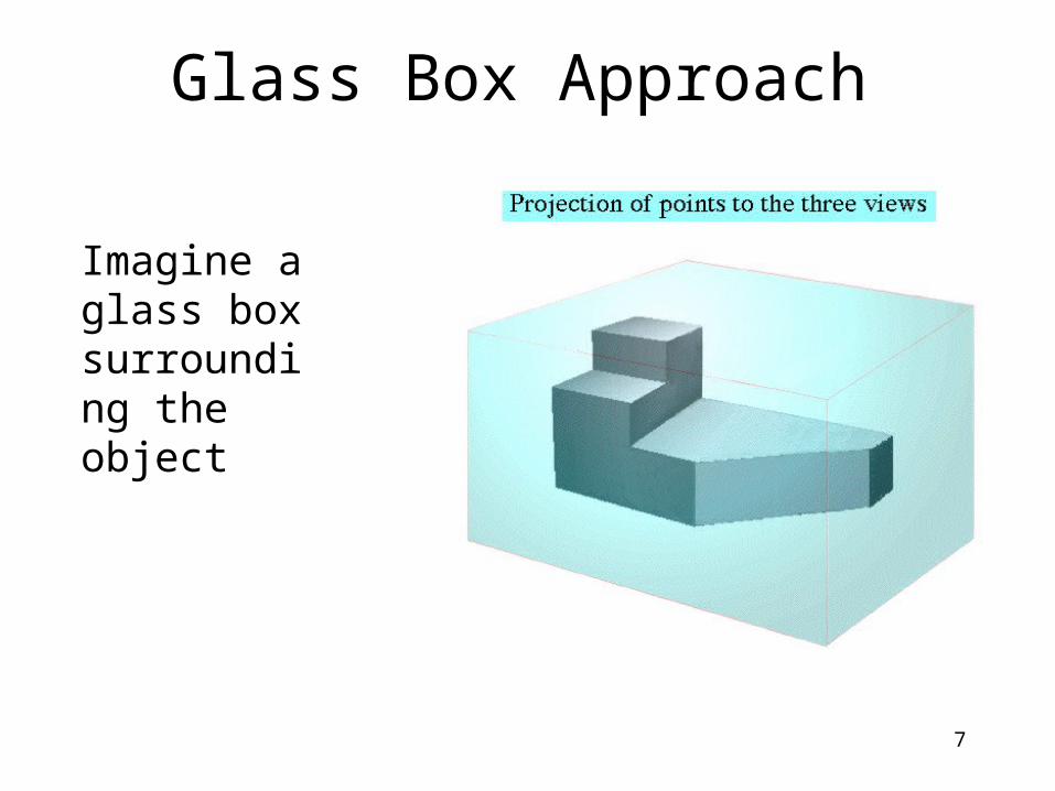
Glass Box Approach
Imagine a glass box surrounding the object
7

Glass Box Approach
See how the corners of the object are projected to the surface of the glass.
One is corner was not projected forward. Can you find it?
8
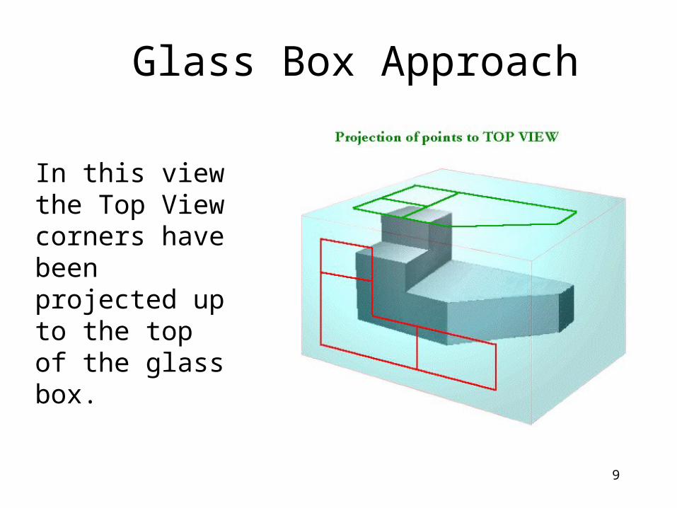
Glass Box Approach
In this view the Top View corners have been projected up to the top of the glass box.
9

Glass Box Approach
In this view the Right Side View corners have been projected horizontally to the side of the glass box.
10

Glass Box Approach
11
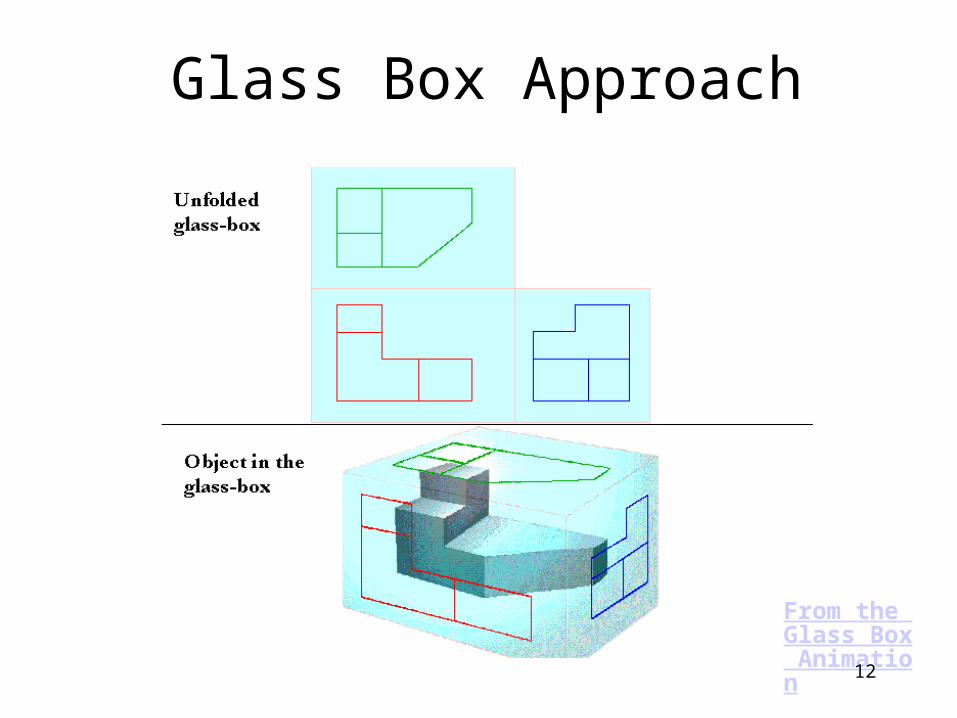
Glass Box Approach
From the Glass Box Animation
12

Alphabet of Lines for Drawings
• A set of drafting standards has been set in order to make sure certain drawings are understandable.
• One such set of rules is the alphabet of lines.
13

Starting your orthographic drawing
• Tape your paper down using the lines of the title box as a guide to align the paper with the T-Square.
• Be sure to use a sharpened pencil to draw the object.
• Do not free hand sketch. Use the T-Square for horizontal lines and one of the Triangles for all vertical lines.
• Measure all lines twice to check for accuracy.
14
ORTHOGRAPHIC DRAWING
BLOCK DATE
YOUR NAME 1
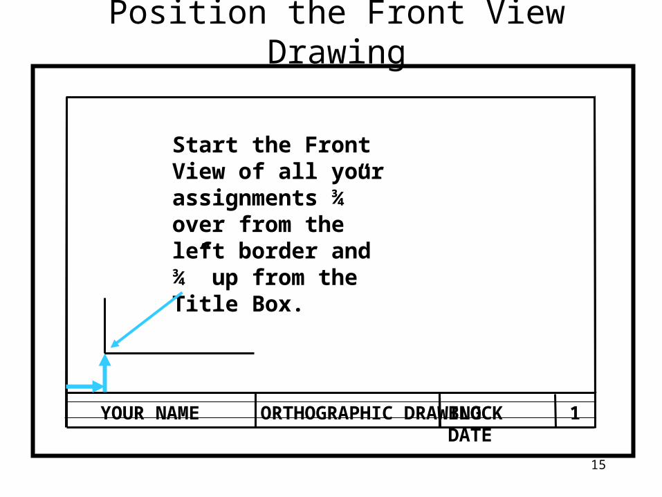
Start the Front View of all your assignments ¾” over from the left border and ¾” up from the Title Box.
Position the Front View Drawing
15

ORTHOGRAPHIC DRAWINGBLOCK DATEYOUR NAME 1
Draw The Front View
Draw the Front view.
Use the T-Square for horizontal lines.
And the T-Square and Triangle for Vertical lines.
16

ORTHOGRAPHIC DRAWINGBLOCK DATEYOUR NAME 1
Draw The Right Side View
2”
Start the right side view 2” to the left of the front view.
Very light horizontal lines (construction lines) from the front view help to locate the base and height of lines in the Right Side View.
The dotted line is a line that is hidden from view. In this case it comes from the step which is in the back in the Right side view.
17

ORTHOGRAPHIC DRAWINGBLOCK DATEYOUR NAME 1
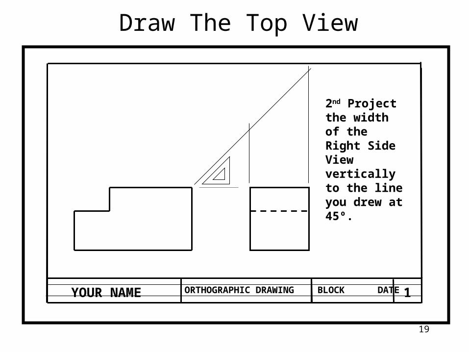
Draw The Top View
1st Draw a 45º from the top right corner of the front view.
This line and the lines in the following steps should be draw light as they are construction lines.
18
ORTHOGRAPHIC DRAWINGBLOCK DATEYOUR NAME 1
Draw The Top View
2nd Project the width of the Right Side View vertically to the line you drew at 45º.
19

ORTHOGRAPHIC DRAWINGBLOCK DATEYOUR NAME 1
Draw The Top View
3rd Project horizontal lines from where the projected width lines intersected the 45º line.
20
ORTHOGRAPHIC DRAWINGBLOCK DATEYOUR NAME 1
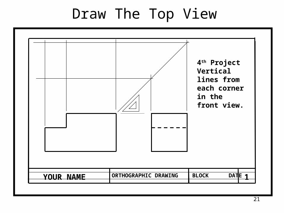
Draw The Top View
4th Project Vertical lines from each corner in the front view.
21

ORTHOGRAPHIC DRAWINGBLOCK DATEYOUR NAME 1
Draw The Top View
5th Darken the lines that represent the Top View of the object and erase the construction lines.
22