Drawing Basic - media.scc.losrios.edumedia.scc.losrios.edu/.../Bk_AutoCAD_2008_Ch04.pdf · Drawing...
32
CHAPTER Drawing Basic Learning Objectives After completing this chapter, you will be able to do the following: Use DRAGMODE to observe an objectbeing dragged into place. Draw circles using the CIRCLE command options. Draw arcs using the ARC command options. Use the ELLIPSE command to draw ellipses and elliptical arcs. Draw polygons using the POLYGON command. Draw rectangles using the RECTANG command options. Draw donuts using the DO NUT command. The decisions you make when drawing circles and arcs with AutoCAD are similar to those you would make whendrawing the items manually. AutoCAD provides many ways to create circles and arcs using the CIRCLE and ARC commands. These methods require specifying the centerlocation and radius or diameter or entering where the outline of the circle or arc should be located. AutoCAD includes additional drawing tools, such as the ELLIPSE, POLYGON, RECTANG, and DONUT commands, to draw a wide variety of shapes. c Dragging Objects into Place 3 Chapter 3 showed how the LINE command displays an image that is "dragged" across the screen before the second endpoint is picked. This image is called a rubberband. The CIRCLE, ARC, ELLIPSE, POLYGON, and RECTANG commands also display a rubberband image to help you decide where to place the object. For example, when you draw a circle using the Center, Radius option, a circle image appears on the screen after you pick the center point. This image gets larger or smaller as you move the pointer. When you pick the desired circle size, a circle replaces the dragged image. See Figure 4-1. The DRAGMODE command affects the visibility of the rubberband. The options are ON, OFF, and Auto. To change the setting, type DRAGMODE: Command: DRAGMODEJ Enter new value [ON/OFF/Auto] <Auto>: (type ON, OFF, or A, and press [Enter]) rubberband:A stretch line that extends from the crosshairs during certain drawing commands. 115
Transcript of Drawing Basic - media.scc.losrios.edumedia.scc.losrios.edu/.../Bk_AutoCAD_2008_Ch04.pdf · Drawing...
CHAPTER
Drawing Basic
Learning Objectives
After completing this chapter, you will be able to do thefollowing:Use DRAGMODE to observe an objectbeing dragged into place.Draw circles using the CIRCLE command options.Draw arcs using the ARC command options.Use the ELLIPSE command to draw ellipses and elliptical arcs.Draw polygons using the POLYGON command.Draw rectangles using the RECTANG command options.Draw donuts using the DO NUT command.
The decisions you make when drawing circles and arcs with AutoCAD are similarto those you would make whendrawing theitems manually. AutoCAD provides manyways to create circles and arcs using the CIRCLE and ARC commands. These methodsrequire specifying the center location and radius or diameter or entering where theoutline of the circle or arc should be located. AutoCAD includes additional drawingtools, such as the ELLIPSE, POLYGON, RECTANG, and DONUT commands, to draw awide variety of shapes.
c Dragging Objects into Place 3Chapter 3 showed how the LINE command displays an image that is "dragged"
across the screen before the second endpoint is picked. This image is called arubberband. The CIRCLE, ARC, ELLIPSE, POLYGON, and RECTANG commands alsodisplay a rubberband image tohelp you decide where toplace the object.
For example, when you draw a circle using the Center, Radius option, a circleimage appears on thescreen afteryou pick thecenter point. This image gets larger orsmaller as you move thepointer. When you pick the desired circle size, a circle replacesthe dragged image. See Figure 4-1.
The DRAGMODE command affects the visibility of the rubberband. The optionsare ON, OFF, and Auto. To change the setting, type DRAGMODE:
Command: DRAGMODEJ
Enter new value [ON/OFF/Auto] <Auto>: (type ON, OFF, orA, and press [Enter])
rubberband:A
stretch line thatextends from the
crosshairs duringcertain drawingcommands.
115
116
Figure 4-1.Dragging a circle toits desired size. The
circle attached to the
crosshairs stretches
like a rubberband
until you pick apoint to define theradius.
Pick the
desired
radius
Cursor movement
The current (last used) mode is shown in brackets. The Auto option is the default.Pressing the [Enter] key keeps the existing status. When the setting is On, you mustenter DRAG during a command sequence to see the objects drag into place.
c Drawing Circles
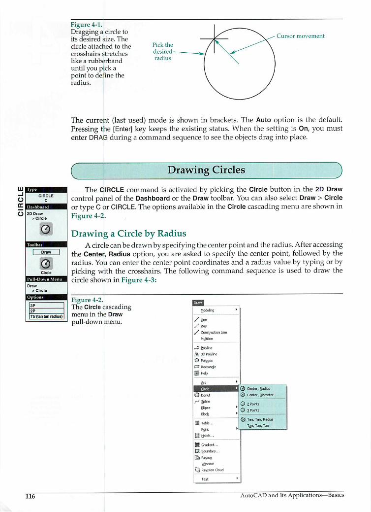
The CIRCLE command is activated by picking the Circle button in the 2D Drawcontrol panel of the Dashboard or the Draw toolbar. You can also select Draw > Circleor type Cor CIRCLE. The optionsavailable in the Circle cascading menu are shown inFigure 4-2.
Drawing a Circle by RadiusA circle canbedrawn by specifying thecenterpoint and the radius. Afteraccessing
the Center, Radius option, you are asked to specify the center point, followed by theradius. You can enter the centerpoint coordinatesand a radius value by typing or bypicking with the crosshairs. The following command sequence is used to draw thecircle shown in Figure 4-3:
Figure 4-2.The Circle cascadingmenu in the Draw
pull-down menu.
U33Modekng
/Line/ Ray/ Construction Line
Myjtiline
JZ Polyline
3> 3D Polyline
O Polygon
• Rectangle
jS Hekx
0 Center, Radius0 Center,Diameter
Arc •
H-7K
@ D_onutr> SP*ne
Ellipse •
Block >
[3 Table...
Pgint •
£$ Hatch...
jjf Gradient...C* Boundary...
> .::-?; K
Wipeout
Q Revision Cloud
Te.t
0 2PointsO 3Points
<5jIan, Tan, RadiusTan, Tan, Tan
AutoCAD and Its Applications—Basics
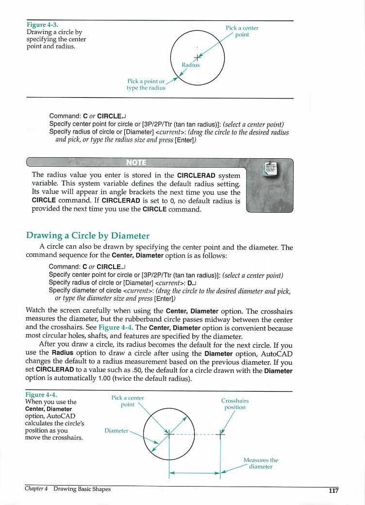
Figure 4-3.Drawing a circle byspecifying the centerpoint and radius.
ick a center
point
Pick a point ortype the radius
Command: C or CIRCLEJ
Specify centerpoint for circle or [3P/2P/Ttr (tan tan radius)]: (select a center point)Specify radius ofcircle or [Diameter] <current>: (drag the circle to the desired radius
and pick, or type the radius size and press [Enter])
CThe radius value you enter is stored in the CIRCLERAD systemvariable. This system variable defines the default radius setting.Its value will appear in angle brackets the next time you use theCIRCLE command. If CIRCLERAD is set to 0, no default radius isprovided the next time you use the CIRCLE command.
Drawing a Circle by DiameterA circle can also be drawn by specifying the center point and the diameter. The
command sequence for the Center, Diameter option is as follows:
Command: C or CIRCLEJ
Specify center point for circle or[3P/2P/Ttr (tan tan radius)]: (select a center point)Specify radius of circle or [Diameter] <current>: DJSpecify diameter of circle <current>: (drag the circle to the desired diameter arid pick,
ortype the diameter sizeand press [Enter])
Watch the screen carefully when using the Center, Diameter option. The crosshairsmeasures the diameter, but the rubberband circle passesmidway between the centerand the crosshairs. See Figure4-4. TheCenter, Diameter option is convenient becausemost circular holes, shafts, and features are specified by the diameter.
After you draw a circle, its radius becomes the default for the next circle. If youuse the Radius option to draw a circle after using the Diameter option, AutoCADchanges the default to a radius measurement based on the previous diameter. If youset CIRCLERAD to a value such as .50, the default for a circle drawn with the Diameteroption is automatically 1.00 (twice the default radius).
Figure 4-4.When you use theCenter, Diameteroption, AutoCADcalculates the circle'sposition as youmove the crosshairs.
Pick a centei
point
Diameter
Chapter 4 Drawing Basic Shapes
Crosshairs
position
Measures the
diameter
117
tangent: Aline,circle, or arc thatcomes into contact
with another circle
or arc at only onepoint.
point of tangency:The point shared bytangent objects.
118
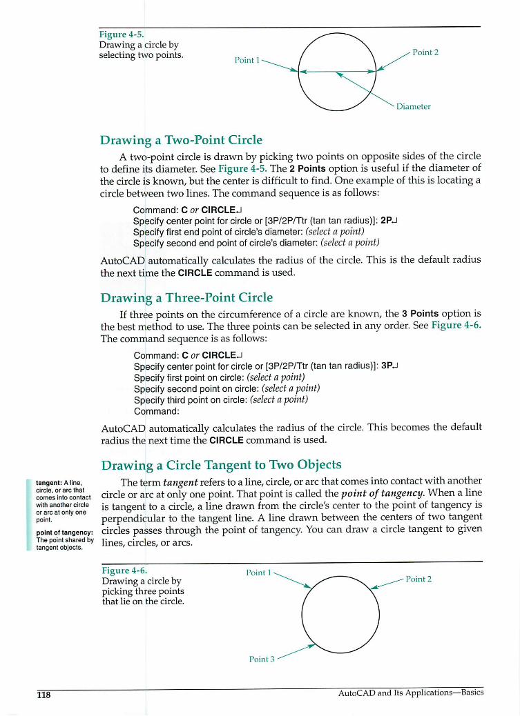
Figure 4-5.Drawing a circle byselecting two points.
PointPoint 2
Diameter
Drawing a Two-Point CircleA two-point circle is drawn by picking two points on opposite sides of the circle
to define its diameter. See Figure 4-5.The 2 Points option is useful if the diameter ofthe circle is known, but the center is difficult to find. One example of this is locating acircle between two lines. The command sequence is as follows:
Command: C or CIRCLEJ
Specify center point for circle or [3P/2P/Ttr (tan tan radius)]: 2PJSpecify first end pointof circle's diameter: (select a point)Specifysecond end point of circle's diameter: (select a point)
AutoCAD automatically calculates the radius of the circle. This is the default radiusthe next time the CIRCLE command is used.
Drawing a Three-Point CircleIf three points on the circumference of a circle are known, the 3 Points option is
the best method to use. The three points can be selected in any order. See Figure 4-6.The command sequence is as follows:
Command: C or CIRCLEJ
Specify center point for circle or [3P/2P/Ttr (tan tan radius)]: 3PJSpecify first point on circle: (select a point)Specify second pointon circle: (select a point)Specify third point on circle: (select a point)Command:
AutoCAD automatically calculates the radius of the circle. This becomes the defaultradius the next time the CIRCLE command is used.
Drawing a Circle Tangent to Two ObjectsThe termtangent refers toa line, circle, orarcthatcomes into contact withanother
circle or arc at only one point. That pointiscalled thepointof tangency. When a lineis tangent to a circle, a line drawn from the circle's center to the point of tangency isperpendicular to the tangent line. A line drawn between the centers of two tangentcircles passes through the pointof tangency. You can draw a circle tangent to givenlines, circles, or arcs.
Figure 4-6.Drawing a circle bypicking three pointsthat lie on the circle.
Point 1
Point 3
Point 2
AutoCAD and Its Applications—Basics
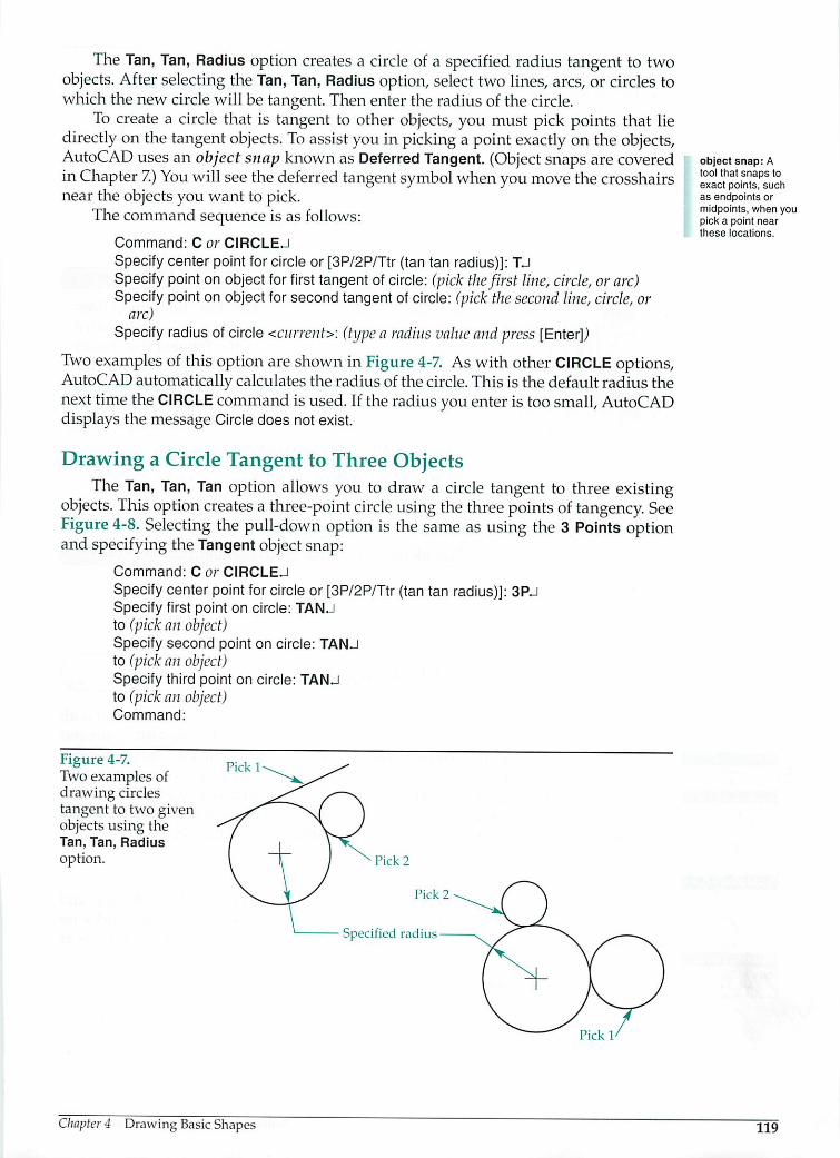
The Tan, Tan, Radius option creates a circle of a specified radius tangent to twoobjects. After selecting the Tan, Tan, Radius option, select two lines, arcs, or circles towhich the new circle will be tangent. Then enter the radius of the circle.
To create a circle that is tangent to other objects, you must pick points that liedirectly on the tangent objects. To assistyou in picking a point exactly on the objects,AutoCAD uses an object snap known as Deferred Tangent. (Object snaps are coveredin Chapter 7) You will see the deferred tangent symbol when you move the crosshairsnear the objects you want to pick.
The command sequence is as follows:
Command: C or CIRCLEJ
Specify center point for circle or [3P/2P/Ttr (tan tan radius)]: TJSpecify point on object for first tangent of circle: (pick thefirst line, circle, orarc)Specify point on object for second tangent ofcircle: (pick the second line, circle, or
arc)Specify radius ofcircle <current>: (type a radius value and press [Enter])
Two examples ofthis option are shown in Figure 4-7. As with otherCIRCLE options,AutoCAD automatically calculates the radius of the circle. This is the default radius thenext time the CIRCLE command is used. If the radius you enter is too small, AutoCADdisplays the message Circle does not exist.
Drawing a Circle Tangent to Three ObjectsThe Tan, Tan, Tan option allows you to draw a circle tangent to three existing
objects. This option creates a three-point circle using the three points of tangency. SeeFigure 4-8. Selecting the pull-down option is the same as using the 3 Points optionand specifying the Tangentobjectsnap:
Command: C or CIRCLEJ
Specify center point for circle or [3P/2P/Ttr (tan tan radius)]: 3PJSpecify first point on circle: TANJto (pick an object)Specify second point on circle: TANJto (pick an object)Specify third point on circle: TANJto (pick an object)Command:
Figure 4-7.Two examples ofdrawing circlestangent to two givenobjects using theTan, Tan, Radiusoption.
Pick 1
Chapter 4 Drawing Basic Shapes
Pick 1'
object snap: Atool that snaps toexact points, suchas endpoints ormidpoints, when youpick a point nearthese locations.
119

arc: Any portion ofa circle.
o
<ARC
2D Draw
> Arc
r
Draw
rArc
Draw
120
Figure 4-8.Two examples ofdrawing circlestangent to threegiven objects.
c
Pick 1
Pick 1Pick 3
'ick 2
Pick 2 Pick 3
JUnlike the Tan, Tan, Radius option, the Tan, Tan, Tan option doesnot automatically recover when a point prompt is answered with apick where notangent exists. Insuch a case, theTangent object snapmustbe manually reactivated for subsequent attempts to makethatpick. TheTangent object snap isoneofthe object snapsdiscussedinChapter7 of this textbook. Fornow, if this happens, type TAN andpress [Enter] at thepointselection prompt. This returns thepick boxso you can pick again.
Exercise 4-1Complete the exercise on the Student CD.
Drawing Arcs
Anarc isdefined asanyportion ofa circle. Arcs arecommonly dimensioned witharadius, butthey can bedrawn by anumber of different methods. The ARC commandcan be accessed by selecting Draw > Arc. The Arc cascading menu contains elevenarc construction options. See Figure 4-9. This is the easiest way to access the ARCcommand andan arc option. The ARC command and its options, however, also can beaccessed by picking the Arc button in the 2D Draw control panel of the Dashboard orinthe Draw toolbar orby typing Aor ARC. The 3 Points option is thedefault.
Drawing a Three-Point ArcThe 3 Points option asks for the start point, a second point along the arc, and
the endpoint. See Figure 4-10. The arc can be drawn clockwise or counterclockwiseand is dragged into position as the endpoint is located. The command sequence is asfollows:
Command: A or ARCJSpecify start point of arc or[Center]: (select thefirst point on the arc)Specify second point of arc or [Center/End]: (select the second point on the arc)Specifyend point of arc: (select the arc's endpoint)Command:
AutoCAD and Its Applications—Basics

Figure 4-9.The Arc cascadingmenu in the Draw
pull-down menu.
Figure 4-10.Drawing an arc bypicking three points.
JJ2[Modefng •
/ Line
/ Bay/ Construction Line
Multiline
O Polyline
3( 3DPolyline
O Polygon
O Rectangle
f*l Helix
Circle •
© Donutr> Spline
Elpse •
Block •
O Table...
Point »
t3 Hatch.,.
JPf Gradient...
EJ Boundary.,,
fo^i Region
Wipeout
Q Revision Cloud
f 3Points
/"] Start, Center, End(*, Start, Center, Anglef. Start, Center, Length
/«" Start, End, Anglej Start, End, Direction
C\ Start, End, P-adius
(", Center, Start, End/". Center, Start, Angle
(7, Center, Start, Length
/v Continue
Text •
Second
point
Start
End
Drawing Arcs Using the Start, Center, End OptionUse the Start, Center, End option when you know the start, center, and endpoint
locations for the arc. With this method, arcs are drawncounterclockwise. Picking thestart and center points establishes the arc's radius. Thepoint selected for the endpointdetermines the arc length. The selected endpoint does not have to be on the radius ofthe arc. See Figure 4-11. The command sequence is as follows:
Command: A or ARCJ
Specify start point of arc or [Center]: (select thefirst point on the arc)Specify second point ofarc or [Center/End]: CJSpecify centerpoint of arc: (select the arc's center point)Specify end point of arc or [Angle/chord Length]: (select the arc's endpoint)Command:
Drawing Arcs Using the Start, Center, Angle OptionWhen the arc's included angle is known, the Start, Center, Angle option maybe
the bestchoice. The included angle isan angle formed between the center, start point,and endpoint ofthe arc. The arc isdrawn counterclockwise, unless a negative angle isspecified. See Figure 4-12.
Chapter 4 Drawing Basic Shapes
included angle:The angle formedbetween the center,start point, andendpoint of the arc.
121

chord length: Thelinear distance
between two pointson a circle or arc.
122
Figure 4-11.Using the Start, Center, End option. Notice that the endpoint does not have to be on the arc.
The third point does not have tolie on the arc surface
End Start
Figure 4-12.Positive and negative angles with the Start, Center, Angleoption.
StartStart
CenterCenter Start
Center
Center
The following shows the commandsequence with a 45° included angle:
Command: A or ARCJ
Specify start point of arc or [Center]: (select thefirst point on the arc)Specify second point of arc or [Center/End]: CJSpecify center pointof arc: (select the arc's center point)Specify end point of arc or [Angle/chord Length]: AJSpecify included angle: 45JCommand:
Start
Drawing Arcs Using the Start, Center, Length OptionThe chord length of an arc is the linear distance between its two endpoints.
This distance can be determined using a chord length table. (A chord length tableis provided in the Standard Tables document in the Reference Materials section of theStudent CD.) For example, a one-unit radius arc with an included angle of 45° has achord length of .765 units.
You can use the Start, Center, Length option to specify the chord length of an arc.With this method, arcs are drawn counterclockwise. A positive chord length gives thesmallest possible arc with that length. A negative chord length results in the largestpossible arc. See Figure 4-13. The following shows the command sequence with achord length of .765:
Command: A or ARCJ
Specify start point ofarc or [Center]: (select thefirst point on the arc)Specify second point of arc or [Center/End]: CJSpecifycenter point of arc: (select the arc's center point)Specify end point of arc or [Angle/chord Length]: LJSpecify length of chord: (type .765 for the smaller arc or -.765 for the larger arc, and
press [Enter])Command:
AutoCAD and Its Applications—Basics

Figure 4-13.Positive and
negative chordlengths with theStart, Center, Lengthoption. +
Center
Start
+Length
V
Exercise 4-2C Complete the exercise on the Student CD.
Start
Drawing Arcs Using the Start, End, Angle OptionAn arc canalso be drawnby picking the startpoint and endpoint and entering the
included angle. Apositive included angle draws the arc counterclockwise, while anegativeangle produces a clockwise arc. See Figure 4-14. The command sequence isas follows:
Command: A or ARCJ
Specify start point of arc or [Center]: (select thefirst point on the arc)Specify second point of arc or [Center/End]: EJSpecify end point ofarc: (select the arc's endpoint)Specify center point of arc or [Angle/Direction/Radius]: AJSpecify included angle: (type apositive or negative angle and press [Enter])Command:
Drawing Arcs Using the Start, End, Direction OptionAn arc can be drawn by picking the start point and endpoint and then using
the mouse to specify the direction of rotation. The distance between the points andthe direction the crosshairs is moved determine the arc's location and size. The arcis started tangent to the direction specified, as shown in Figure4-15. The commandsequence is as follows:
Command: A or ARCJ
Specify start point of arc or [Center]: (select thefirst point on the arc)Specify second point of arc or [Center/End]: EJSpecify end point ofarc: (select the arc's endpoint)Specify center point of arc or [Angle/Direction/Radius]: DJSpecify tangent direction for thestartpoint of arc: (pick the direction from the start
point, or type the direction in degrees and press [Enter])Command:
Figure 4-14.Positive and
negative angles withthe Start, End, Angleoption.
Chapter 4 Drawing Basic Shapes
End
Start Start
123

124
Figure 4-15.Using the Start, End,Direction option.
Direction
Start
Start
Direction
End
Drawing Arcs Using the Start, End, Radius OptionA positive radius value for the Start, End, Radius option results in the smallest
possible arc between the start point and endpoint. A negative radius gives the largestarc possible. See Figure 4-16. Arcs can only be drawn counterclockwise with thisoption. The command sequence is as follows:
Command: A or ARCJ
Specify start point ofarc or [Center]: (select thefirst point on the arc)Specify second point of arc or [Center/End]: EJSpecify end point of arc: (select the arc's endpoint)Specify center point of arc or [Angle/Direction/Radius]: RJSpecify radius ofarc: (pick ortype apositive ornegative radius and press [Enter])Command:
Exercise 4-3Complete the exercise on the Student CD.
Drawing Arcs Using the Center, Start, End OptionThe Center, Start, End option is a variation of the Start, Center, End option. See
Figure 4-17. Use theCenter, Start, End option when it iseasier tobeginby locating thecenter. The command sequence is as follows:
Command: A or ARCJ
Specify start point of arc or [Center]: CJSpecifycenter point ofarc: (pick the center point)Specifystart point ofarc: (pick the start point)Specifyend point of arc or [Angle/chord Length]: (pick the arc's endpoint)Command:
Figure 4-16.Using the Start,End, Radius optionwith a positive andnegative radius.
Start
+RadiusEnd
Start
-Radius
AutoCAD and Its Applications—Basics
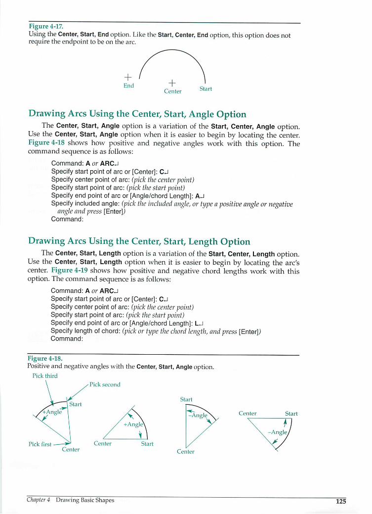
Figure 4-17.Using theCenter, Start, End option. Like theStart, Center, End option, thisoption does notrequire the endpoint to be on the arc.
+End
Start
Drawing Arcs Using the Center, Start, Angle OptionThe Center, Start, Angle option is a variation of the Start, Center, Angle option.
Use the Center, Start, Angle option when it is easier to begin by locating the center.Figure 4-18 shows how positive and negative angles work with this option. Thecommand sequence is as follows:
Command: A or ARCJ
Specify start point of arc or [Center]: CJSpecify center point of arc: (pick the center point)Specify start point of arc: (pick the start point)Specify end point of arc or [Angle/chord Length]: AJSpecify included angle: (pick the included angle, or type a positive angle or negative
angle andpress [Enter])Command:
Drawing Arcs Using the Center, Start, Length OptionThe Center, Start, Length option is a variation of the Start, Center, Length option.
Use the Center, Start, Length option when it is easier to begin by locating the arc'scenter. Figure 4-19 shows how positive and negative chord lengths work with thisoption. The command sequence is as follows:
Command: A or ARCJ
Specify start point of arc or [Center]: CJSpecify center point ofarc: (pick the center point)Specify start point of arc: (pick the start point)Specify end point of arc or [Angle/chord Length]: LJSpecify length of chord: (pick or type the chord length, and press [Enter])Command:
Figure 4-18.Positive and negative angles with the Center, Start, Angle option.
Pick third
Pick second
Pick first - —**• CenterCenter
Chapter 4 Drawing BasicShapes
Start
Center
Center Start
125

126
Figure 4-19.Positive and
negative chordlengths with theCenter, Start, Lengthoption.
Pick first
Pick
second
Pick third
Start
-Length
Continuing Arcs from a Previously Drawn Arc or LineAn arc can be continued from the previous arc or line. To do so, select Draw > Arc
>Continue. The Continue option canalso beaccessed bybeginning theARC commandand then pressing the [Enter] key, pressing the space bar, or selecting Enter from theshortcut menu when prompted to specify the start point of the arc.
When a series of arcs are drawn in this manner, each consecutive arc is tangentto the object before it. The start point and direction are taken from the endpoint anddirection of the previous arc. See Figure 4-20.
The Continue option canalso beused toquickly drawanarc tangent totheendpointofa previously drawn line. See Figure 4-21. The command sequence isas follows:
Command: L or LINEJ
Specify first point: (select a point)Specify next point or [Undo]: (select a second point)Specify next point or [Undo]: JCommand: A or ARCJSpecify start point of arc or [Center]: (press the space bar or [Enter] to place the start
point ofthe arc at the end ofthe previous line)Specify end point ofarc: (select the endpoint of the arc)Command:
Figure 4-20.Using the Continueoption to draw threetangent arcs.
Exercise 4-4Completethe exercise on the Student CD.
Third arc
End
Second arc
Third arc
starts here
First arc
Second arc
starts here
Start
AutoCAD and Its Applications—Basics
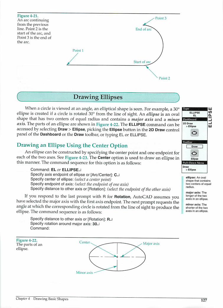
Figure 4-21.An arc continuingfrom the previousline. Point 2 is the
start of the arc, andPoint 3 is the end ofthe arc.
C
Point 1
Drawing Ellipses
Point 3
End of arc
Start of arc
Point 2
)When a circle isviewed atan angle, anelliptical shape is seen. For example, a 30°
ellipse is created if a circle is rotated 30° from the line ofsight. An ellipse is an ovalshape that has two centers of equal radius and contains a major axis and a minoraxis. Theparts ofan ellipse are shownin Figure4-22. The ELLIPSE commandcan beaccessed by selecting Draw >Ellipse, picking the Ellipse button in the 2D Draw controlpanelof the Dashboard or the Draw toolbar, or typing EL or ELLIPSE.
Drawing an Ellipse Using the Center OptionAnellipse can beconstructed by specifying the center point and one endpoint for
each of the two axes. See Figure 4-23. The Center option isused todraw an ellipse inthis manner. Thecommand sequence for this optionis as follows:
Command: EL or ELLIPSEJ
Specify axis endpoint of ellipse or [Arc/Center]: CJSpecify center of ellipse: (select a center point)Specify endpoint of axis: (select the endpoint ofone axis)Specify distance to other axis or[Rotation]: (select the endpoint ofthe other axis)
If you respond to the last prompt with Rfor Rotation, AutoCAD assumes youhave selected the major axis with the first axis endpoint. The next prompt requests theangle atwhich the corresponding circle isrotated from the line of sight toproduce theellipse.The command sequence is as follows:
Specify distance to other axis or [Rotation]Specify rotation around major axis: 30JCommand:
Figure 4-22.The parts of anellipse.
Chapter 4 Drawing Basic Shapes
Cent
Minor axis
RJ
Major axis
ELLIPSE
2D Draw
> Ellipse
Draw
LU
oEllipse
Draw
> Ellipse
ellipse: An ovalshape that containstwo centers of equalradius.
major axis: Thelonger of the twoaxes in an ellipse.
minor axis: The
shorter of the two
axes in an ellipse.
127

128
Figure 4-23.Drawing an ellipseby picking the center and an endpoint for eachaxis.
Endpoint 1
Center point
Endpoint 2
The 30 response draws an ellipse that is created when a circle is rotated 30° from thelineofsight. A0response draws anellipse withtheminor axis equalto themajor axis—that is,a circle. AutoCAD rejects any rotationanglebetween 89.99994° and 90.00006° orbetween 269.99994° and 270.00006°. Figure 4-24 shows the relationship among severalellipses having thesame major axis length, but different rotation angles.
Drawing an Ellipse Using the Axis, End OptionThe Axis, End option establishes the first axis and one endpoint of the second axis.
The first axis may beeither the major orminor axis, depending onwhat you enter for thesecond axis. After you pick thefirst axis, the ellipse is dragged withthe crosshairs untilyou pick a point. The command sequence for theellipses in Figure 4-25 isas follows:
Command: EL or ELLIPSEJSpecify axis endpoint of ellipse or[Arc/Center]: (select an axis endpoint)Specify otherendpoint of axis: (select the other endpoint ofthe axis)Specify distance to other axis or[Rotation]: (select adistancefrom the midpoint ofthe
first axis to the end ofthe second axis and press [Enter])Command:
Figure 4-24.Ellipse rotation angles.
Major axis Endpoint 1
Figure 4-25.Constructing the sameellipse by choosing different axisendpoints.
/ Endpoint3 / Endpoint 1/
Endpoint1\ ^*~ | ""---^ /Endpoint?
Endpoint 2
Endpoint 3
AutoCAD and Its Applications—Basics

Exercise 4-5Complete the exercise on the Student CD.
Drawing Elliptical ArcsThe Arc option of the ELLIPSE command is used to draw elliptical arcs. The Arc
optioncanbespecified fromwithin the ELLIPSE command, or itcanbe entered directlyby picking the Ellipse Arcbutton on the 2D Draw control panel of the Dashboard or theDraw toolbar. The command sequence for the Arc option is as follows:
Command: EL or ELLIPSEJ
Specify axis endpoint of ellipse or [Arc/Center]: AJSpecify axis endpoint of elliptical arc or [Center]: (pick thefirst axisendpoint)Specify other endpoint of axis: (pick the second axis endpoint)Specify distance to other axis or [Rotation]: (pick the distancefor the second axis)Specify start angle or [Parameter]: OJSpecify end angle or [Parameter/Included angle]: 90JCommand:
After selecting thesecond endpoint ofthefirst axis, you candrag theshapeofa fullellipse.This can help you visualize the other axis. The distance for the second axis is from theellipse's center to thepoint you pick. Enter a start angle. The start and end angles are theangularrelationships between theellipse's center and thearc's endpoints. Theangle of theelliptical arcisestablished from theangle ofthefirst axis. A0° startangle begins thearcatthefirstendpointofthefirstaxis. A45° startanglebeginsthearc45° counterclockwise fromthe first endpoint of the first axis. End anglesare alsoestablished counterclockwise fromthe start point. Figure 4-26 shows the elliptical arc drawn with the previous commandsequence and displays samplearcswith different start and end angles.
Using the Parameter option
With the Parameter option, AutoCAD uses a different means of vector calculation to create the elliptical arc. The Parameter option requires the same input used fordrawing other elliptical arcs, until the Specify start angle or [Parameter]: prompt. Theresults are similar, but the command sequence is as follows:
Specify start angle or [Parameter]: PJSpecify start parameter or [Angle]: (pick the start point orenter a value)Specify end parameter or [Angle/Included angle]: (pick the endpoint orenter a value)Command:
Figure 4-26.Drawing ellipticalarcs. Note the three
examples at thebottom created bythree different anglesettings.
Axis endpoint 1(0° start angle)
0° to 180c
arc
Chapter 4 Drawing Basic Shapes
0° to 270c
arc
Axis endpoint 280° start angle)
90° end
angle
90° to 270"
arc
2D Draw
> Ellipse Arc
Draw
oEllipse Arc
Draw
> Ellipse> Arc
129

Using the Included angle optionThe Included angle option establishes an included angle beginning at the start
angle. This option requires the same input used for drawing other elliptical arcs untilthe Specify end angle or [Parameter/Included angle]: prompt. The command sequence isas follows:
Specify end angle or [Parameter/Included angle]: USpecify included angle for arc <current>: (enter the included angle)Command:
Rotating an elliptical arc around its axis
The Rotation option for drawing an elliptical arc is similar to the Rotation optionfor drawing a full ellipse, which was discussed earlier. This option allows you to rotatethe elliptical arc about the first axis by specifying a rotation angle. Refer to Figure 4-24for examples of various rotation angles. This option requires the same input used fordrawing other elliptical arcs, until the Specifydistance to other axis or [Rotation]: prompt.The command sequence is as follows:
Specify distance to other axis or [Rotation]: RJSpecify rotation around major axis: (enter rotation value)Specify start angle or [Parameter]: (enter startangle)Specify end angle or [Parameter/Included angle]: (enterend angle)Command:
Drawing an elliptical arc using the Center option
The Center option for drawing an elliptical arc lets you establish the center of theellipse. See Figure 4-27. This option requires the same input used for drawing otherelliptical arcs, until the Specify axis endpoint of elliptical arc or [Center]: prompt. Thecommand sequence is as follows:
Specify axis endpoint of elliptical arc or [Center]: CJSpecify center of elliptical arc: (select the ellipse's center point)Specifyendpoint ofaxis: (select the endpoint of the axis)Specifydistance to other axis or [Rotation]: (select the endpoint of the other axis)Specifystart angle or [Parameter]: (enter start angle)Specify end angle or [Parameter/Included angle]: (enterend angle)Command:
Figure 4-27. ^^ Axis endpoint,Drawing elliptical y*~ ^^\^ 0° start anglearcs with the Center
option.
180°end
angle
Pick thei/ x Drag thecenter image
130 AutoCAD and Its Applications—Basics

cThe setting of the PELLIPSE system variable affects the way anellipse can be edited. An ellipse drawn when PELLIPSE is set at 0 isa true elliptical object, while an ellipse drawn when PELLIPSE is setat 1 is a polyline ellipse. A true elliptical object maintains its elliptical shape during grip editing, which is discussed in Chapter 12of this text. The vertices of a polyline ellipse can be moved out ofthe elliptical shape. The Arc option of the ELLIPSE command is notavailable when PELLIPSE is set to 1.
Exercise 4-6Complete the exercise on the Student CD.
c Drawing Regular Polygons 3A regular polygon is any closed-planegeometric figure with three or more equal
sides and equal angles. For example, a hexagon is a six-sided regular polygon. ThePOLYGON command is used to draw any regular polygon with up to 1024 sides.
The POLYGON command can be accessed by selecting Draw > Polygon, pickingthe Polygon button in the 2D Draw control panel of the Dashboard or the Draw toolbar,or typing POL or POLYGON. Regardless of the method used to select the command,youare first prompted for the number ofsides. For example, if you want an octagon(apolygon with eight sides), enter 8.
CThe number of sides you enter becomes the default for the next timeyou use the POLYGON command. This value is saved in the POLY-SIDES system variable.
Next, AutoCAD prompts for the center or edge of the polygon. If you reply bypicking a point on the screen, this pointbecomes the center of the polygon.
You are then asked if you want to have the polygon inscribed within or circumscribed outside of an imaginary circle. An inscribed polygon is one that is drawninside an imaginary circle so thatitscorners touch thecircle. Acircumscribed polygonisdrawnoutside ofan imaginary circle so that thesides ofthe polygon are tangent tothe circle. See Figure4-28. The I (inscribed) or C (circumscribed) option you selectbecomes the default for the next polygon. With either option, you must specify theradius of thecircle. Finally, youmustpick thecenter orspecify an edgefor thepolygon.Notice that picking the center is the default.
Chapter 4 Drawing BasicShapes
regular polygon:A closed geometricfigure with three ormore equal sidesand equal angles.
inscribed polygon:A polygon that isdrawn inside an
imaginary circleso that its corners
touch the circle.
circumscribed
polygon: A polygonthat is drawn outside
ot an imaginarycircle so that the
sides of the polygonare tangent to thecircle.
131

Figure 4-28.Polygons canbe inscribed in
a circle (left) orcircumscribed
around a circle
(right).
Inscribed Polygon
Specified\ radius
Specifiedradius
Circumscribed Polygon
JHexagons (six-sidedpolygons) are commonly drawn to represent boltheads and nuts on mechanical drawings. Keep in mind that thesefeatures are normally dimensioned across the flats.Todraw a polygonto be dimensioned across the flats, circumscribe it. The radius youenter is equal to one-half the distance across the flats. The distanceacross the corners is specified when the polygon must be confinedwithin a circular area. In this case, use an inscribed polygon.
polyline: A series oflines and arcs that
constitute a singleobject.
Polygons are polylines and can be easily edited using the PEDIT (polyline edit)command. The PEDIT command is discussed in Chapter 14of this textbook.
z
<h-
oLU
DC
RECTANGLE
RECTANG
REC
2D Draw
> Rectangle
a
Draw
Rectangle
™?MTDraw
> Rectangle
132
Exercise 4-7Complete the exercise on the Student CD.
c Drawing Rectangles )The RECTANG command allows you to draw rectangles easily. To use this
command, pick one corner and then the opposite diagonal corner to establish therectangle. See Figure 4-29. The RECTANG command can be accessed by picking theRectangle button in the 2D Draw control panel of the Dashboard or in the Draw toolbar;by selecting Draw > Rectangle; or by typing REC, RECTANG, or RECTANGLE.
Rectangles are polylines and can be edited using the PEDIT command. Since arectangle isa polyline, it is treated as oneentity until it is exploded. After it is exploded,the individual sides can be edited separately. The EXPLODE command is discussed inChapter 14 of this textbook.
Drawing Rectangles with Line WidthThe Width option of the RECTANG command is used to adjust the width of the
rectangle in the XY plane. The following sequence is used to create a rectangle with .5wide lines:
Command: REC, RECTANG, or RECTANGLEJSpecify first corner point or [Chamfer/Elevation/Fillet/Thickness/Width]: WJSpecify line width for rectangles <current>: .5JSpecify first corner point or [Chamfer/Elevation/Fillet/Thickness/Width]:
AutoCAD and Its Applications—Basics
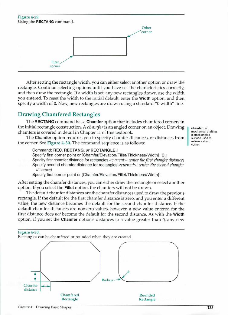
Figure 4-29.Using the RECTANG command.
First
corner
Other
'corner
After setting the rectangle width, you can either select another option or draw therectangle. Continue selecting options until you have set the characteristics correctly,and then draw the rectangle. If a width is set, any new rectangles drawn use the widthyou entered. To reset the width to the initial default, enter the Width option, and thenspecify a width of 0. Now, new rectangles are drawn using a standard "0 width" line.
Drawing Chamfered RectanglesThe RECTANG command has a Chamfer option that includes chamfered corners in
the initial rectangle construction. A chamfer is an angled corner on an object. Drawingchamfers is covered in detail in Chapter 11 of this textbook.
The Chamfer option requires you to specify chamfer distances, or distances fromthe corner. See Figure 4-30. The command sequence is as follows:
Command: REC, RECTANG, or RECTANGLEJSpecify first corner point or [Chamfer/Elevation/Fillet/Thickness/Width]: CJSpecifyfirst chamferdistance for rectangles <current>: (enter thefirst chamfer distance)Specifysecond chamfer distance for rectangles <current>: (enter the second chamfer
distance)Specify first corner point or [Chamfer/Elevation/Fillet/Thickness/Width]:
After setting the chamfer distances, you can either draw the rectangle or select anotheroption. If you select the Fillet option, the chamfers will not be drawn.
The default chamfer distances are the chamfer distances used to draw the previousrectangle. If the default for the first chamfer distance is zero, and you enter a differentvalue, the new distance becomes the default for the second chamfer distance. If thedefault chamfer distances are nonzero values, however, a new value entered for thefirst distance does not become the default for the second distance. As with the Width
option, if you set the Chamfer option's distances to a value greater than 0, any new
Figure 4-30.Rectangles can be chamfered or rounded when they are created.
Chamfer
distance
Chamfered
Rectangle
Chapter 4 Drawing BasicShapes
Radius
Rounded
Rectangle
chamfer: In
mechanical drafting,a small angledsurface used torelieve a sharpcorner.
133

fillet: A rounded
interior corner.
round: A rounded
exterior corner.
rectangles created are automatically chamfered. New rectangles continue to be createdwith chamfers until you reset the chamfer distances to 0 or use the Fillet option tocreate rounded corners.
Drawing Rounded RectanglesAfillet is a rounded interior corner on an object and a round is a rounded exterior
corner. AutoCAD uses the termfillet to describe both fillets and rounds. See Figure 4-30.Drawing fillets and rounds is covered in detail in Chapter 11 of this textbook. This isa brief introduction to drawing rounds on rectangles.
Rounds can be automatically drawn on rectangles using the Fillet option of theRECTANG command. After selecting the option, you must enter the round radius:
Command: REC, RECTANG, or RECTANGLEJSpecify first corner point or [Chamfer/Elevation/Fillet/Thickness/Width]: FJSpecify fillet radius for rectangles <current>: (enter a round radius or press [Enter] to
accept the default)Specify first corner point or [Chamfer/Elevation/Fillet/Thickness/Width]:
The default round radius is the radius of the rounds in the previous rectangle. Oncea radius is specified, the RECTANG command automatically draws rounds on all newrectangles. In order to draw rectangles without rounds, the radius must be set to 0.
Specifying Rectangle AreasWhen you know the area of a rectangle and the length of one of its sides, the
rectangle can be drawn using the Area option. This option is available after the firstcorner point of the rectangle is picked:
Specify other corner point or [Area/Dimensions/Rotation]: A
You are then prompted to enter the total area for the rectangle. Enter a value thatcorresponds to the current units. The following sequence is used to draw a rectanglewith an area of 45 in2when the length is known:
Enter area of rectangle in current units <current>: 45JCalculate rectangle dimensions based on [Length/Width] <current>: LJEnter rectangle length <current>: 10JCommand:
After you enter the length, AutoCAD calculates the width dimension automaticallyand draws the rectangle.
Specifying Rectangle DimensionsAutoCAD provides a Dimensions option for the RECTANG command. The option
is available after the first corner of the rectangle is picked.Enter Dto access the Dimensions option. You are then prompted to enter the length
and width of the rectangle. In the following example, a 5 x 3 rectangle is specified:
Specify other corner point or [Area/Dimensions/Rotation]: DJSpecify length for rectangles <current>: 5JSpecify width for rectangles <current>: 3JSpecify other corner point or [Area/Dimensions/Rotation]: (move the crosshairs to the
desired quadrant andpick a point)Command:
After specifying the length and width, AutoCAD asks for the other corner point.If you wish to change the dimensions, select the Dimensions option again. If thedimensions are correct, you can specify the other corner point to complete the rectangle. The second corner point determines which of four possible rectangles is drawn.See Figure 4-31.
134 AutoCAD and Its Applications—Basics
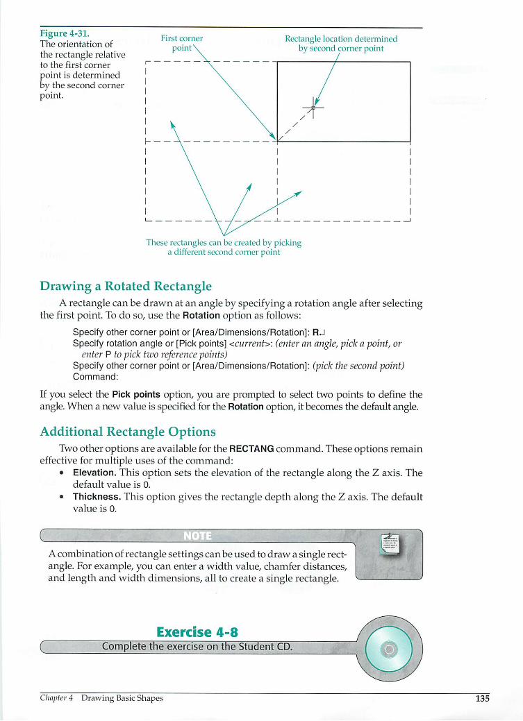
Figure 4-31.The orientation of
the rectangle relativeto the first corner
point is determinedby the second cornerpoint.
First corner
pointRectangle location determined
by second corner point
These rectangles can be created by pickinga different second corner point
Drawing a Rotated RectangleA rectangle can be drawn at an angle by specifying a rotation angle after selecting
the first point. To do so, use the Rotation option as follows:
Specify other corner point or [Area/Dimensions/Rotation]: RJSpecify rotation angle or [Pick points] <current>: (enter anangle, pick a point, or
enter P to pick two reference points)Specify other corner point or [Area/Dimensions/Rotation]: (pickthesecondpoint)Command:
If you select the Pick points option, you are prompted to select two points to define theangle. When a new value is specifiedfor the Rotation option, itbecomes the default angle.
Additional Rectangle OptionsTwoother options are available for the RECTANG command. These options remain
effective for multiple uses of the command:• Elevation. This option sets the elevation of the rectangle along the Z axis. The
default value is 0.
• Thickness. This option gives the rectangle depth along the Z axis. The defaultvalue is 0.
CAcombination of rectangle settings can be used to draw a single rectangle. For example, you can enter a width value, chamfer distances,and length and width dimensions, all to create a single rectangle.
cExercise 4-8
Complete the exercise on the Student CD.
Chapter 4 Drawing Basic Shapes 135

oQ
DONUT
DOUGHNUT
DO
. IS1
Draw
> Donut
136
c Drawing Donuts and Solid Circles 3The DONUT command allows you to draw a thick circle. It can have any inside and
outside diameters or be completely filled. See Figure 4-32. Donuts drawn in AutoCADare actually polyline arcs with width. Polylines are covered in detail in Chapter 14.
The DONUT command can be accessed by selecting Draw > Donutor by typing DO,DONUT, or DOUGHNUT as follows:
Command: DO, DONUT, or DOUGHNUTJ
Specify inside diameter of donut <current>\ 3JSpecify outside diameter of donut <current>: 5JSpecifycenter of donut or <exit>: (select the donut's center point)Specifycenter of donut or <exit>: (select the center pointfor another donut, orpress
[Enter] to end the command)
The current diameter settings are shown in brackets. New diameters can be entered,or the current value can be accepted by pressing the [Enter] key. An inside diameter of0 produces a solid circle.
After you select the center point, the donut appears on the screen. You may pickanother center point to draw the same size donut in a new location. The DONUTcommand remains active until you press [Enter] or cancel by pressing [Esc].
When the FILL mode is turned off, donuts appear as segmented circles or concentric circles. FILL can be used transparently by entering 'FILL while inside the DONUTcommand. Enter ON or OFF as needed. The fill display for previously drawn donuts isupdated when the drawing is regenerated.
jThe setting for the inside diameter of a donut is stored in theDONUTID system variable. The setting for the outside diameter isstored in the DONUTOD system variable. If the value of DONUTID isgreater than the value of DONUTOD, the values are switched whenthe next donut is drawn.
Figure 4-32.The appearance of adonut depends on itsinside and outside
diameters and the
current FILL mode.
Exercise 4-9Complete the exercise on the Student CD.
Fill On Fill On
I.D. = 0
Fill Off Fill Off
I.D. = 0
AutoCAD and Its Applications—Basics

Chapter TestAnswer thefollowing questions. Write your answers on a separate sheet ofpaperorcomplete the electronic chapter test on the Student CD.
1. Which command controls the visibility of the rubberband image that appears bydefault when you create objects?
2. Name the system variable used to set the default radius when drawing circles.3. Explain how to create a circle with a diameter of 2.5 units.4. Define the term point of tangency.5. What option of the CIRCLE command creates a circle of a specific radius that is
tangent to two existing objects?6. Identify how to access the option that allows you to draw a circle tangent to three
objects.7. Briefly explain how to create a three-point arc.8. Define the term included angle as it applies to an arc.9. Explain the procedure to draw an arc beginning with the center point and hav
ing a 60° included angle.10. List the three input options that can be used to draw an arc tangent to the end-
point of a previously drawn arc.11. What is the default option if the ARC command is entered at the keyboard?12. Briefly describe the procedure to draw an ellipse using the Axis, End option.13. What is the ELLIPSE rotation angle that causes you to draw a circle?14. Identify two ways to access the Arc option for drawing elliptical arcs.15. Name the AutoCAD system variable that lets you draw a true ellipse or a poly
line ellipse with the ELLIPSE command.16. Name at least three commands you could use to create a rectangle.17. Explain how to draw a hexagon measuring 4" (102 mm) across the flats.18. Given the distance across the flats of a hexagon, would you use the Inscribed or
Circumscribed option to draw the hexagon?19. Name the control panel on the Dashboard where the RECTANG command is
found.
20. Name the command option designed specifically for drawing rectangles with aspecific line thickness.
21. Name the command option used to draw rectangles with rounded corners.22. Explain how to draw two donuts with an inside diameter of 6.25 and an outside
diameter of 9.50.
23. Describe a method for drawing a solid circle.24. Explain how to turn the FILL mode off.25. Give the easiest keyboard shortcut for the following commands:
A. CIRCLE
B. ARC
C. ELLIPSE
D. POLYGON
E. RECTANG
F. DONUT
Chapter 4 Drawing Basic Shapes 137
138
Drawing ProblemsStart AutoCAD and usea template ora setup option ofyour choice. Do notdraw dimensionsor text. Use your own judgment and approximate dimensions ifneeded.
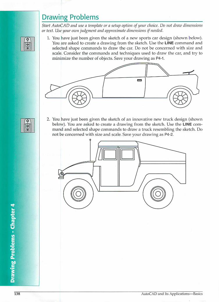
1. You have just been given the sketch of a new sports car design (shown below).You are asked to create a drawing from the sketch. Use the LINE command andselected shape commands to draw the car. Do not be concerned with size andscale. Consider the commands and techniques used to draw the car, and try tominimize the number of objects. Save your drawing as P4-1.
2. You have just been given the sketch of an innovative new truck design (shownbelow). You are asked to create a drawing from the sketch. Use the LINE command and selected shape commands to draw a truck resembling the sketch. Donot be concerned with size and scale. Save your drawing as P4-2.
AutoCAD and Its Applications—Basics

3. Use the LINE and CIRCLE command options to draw the objects below. Do notinclude dimensions. Save the drawing as P4-3.
4. Use the CIRCLE and ARC command options to draw the object below. Do notinclude dimensions. Save the drawing as P4-4.
R3.000
0.750
Chapter 4 Drawing BasicShapes
m
139
140
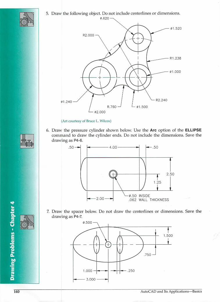
5. Draw the following object. Do not include centerlines or dimensions.0.620
01.240
02.000
(Art courtesy of Bruce L. Wilcox)
R2.000
R2.240
01.500
01.520
R1.238
01.000
6. Draw the pressure cylinder shown below. Use the Arc option of the ELLIPSEcommand to draw the cylinder ends. Do not include the dimensions. Save thedrawing as P4-6.
.50-*-| I- 4.00 •-! r*-.50
2.50
0.50 INSIDE
.062 WALL THICKNESS
7. Draw the spacer below. Do not draw the centerlines or dimensions. Save thedrawing as P4-7.
0.500
T1.500
AutoCAD and Its Applications—Basics

Draw the following object. Do not draw the dimensions. Save the drawing as P4-3.000
4X 0.312
- 5.376
9. Draw the following object. Do not draw the centerlines or dimensions. Save thedrawing as P4-9.
2X 0.38
Chapter 4 Drawing Basic Shapes
16.75
(4 HOLES)
141
rnl
r-J
LH
142
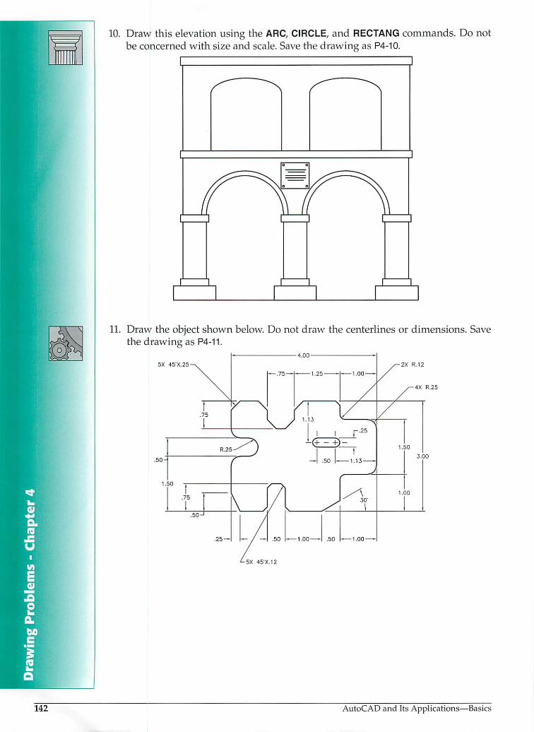
10. Draw this elevation using the ARC, CIRCLE, and RECTANG commands. Do notbe concerned with size and scale. Save the drawing as P4-10.
11. Draw the object shown below. Do not draw the centerlines or dimensions. Savethe drawing as P4-11.
5X 45X25 2X R.12
.50-
•5X 45X12
AutoCAD and Its Applications—Basics
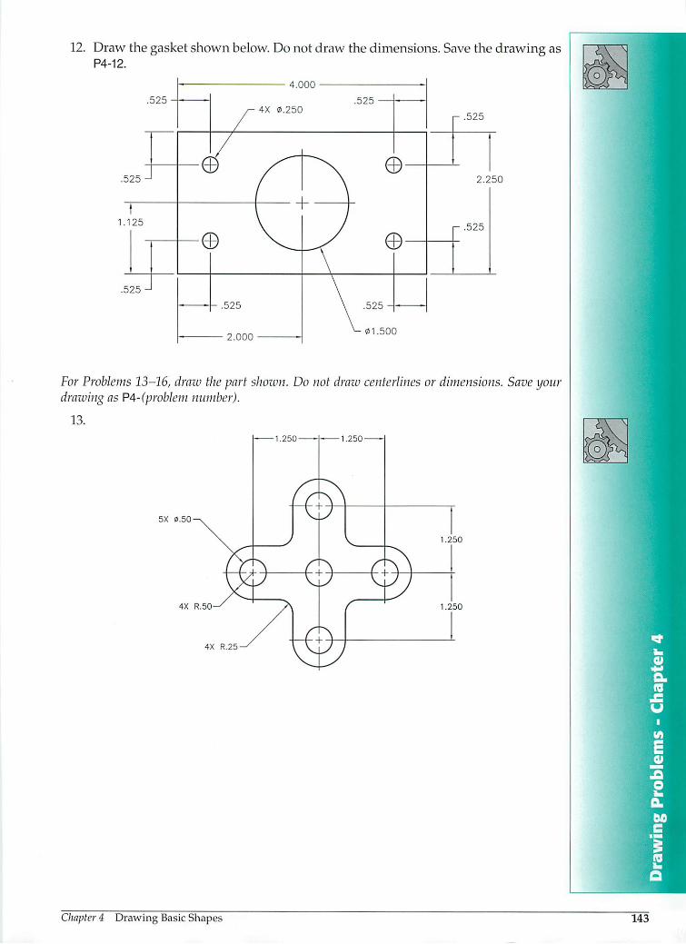
12. Draw the gasket shown below. Do not draw the dimensions. Save the drawing asP4-12.
.525 2.250
1.125
For Problems 13-16, draw the part shown. Do not draw centerlines ordimensions. Save yourdrawing as P4-(problem number).
13.
5X 0.50
4X R.50
4X R.25
Chapter 4 Drawing Basic Shapes 143

14.
R.25
1.00
15.
83
19- 32
13
2513
©•13
51
J
5164
&
2X 010
13
2X 6 57
02
16.
.500
144 AutoCAD and Its Applications—Basics

17. Draw the pipe fitting shown. Save the drawing as P4-17.
2X R.2
0.125
3X 01.900
y i v
1
0.125
2.525
1.200
3X 01.200
2.150
18. Draw the ellipse template shown. Save the drawing as P4-18.
Cliapter 4 Drawing Basic Shapes
ELLIPSE TABLEKEY MAJOR DIA
A .9951
Q
M
145
k
146
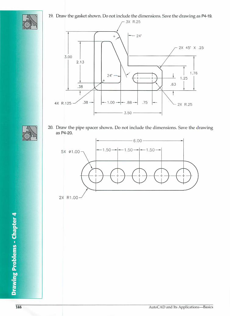
19. Draw the gasket shown. Do not include the dimensions. Save the drawing as P4-19.3X R.25
T
3.00
2.13
.38
4X R.125 S -38
24"
24' \S
t + +
1.00——.88— .75
3.50 -
2X 45* X .25
1.76
1.25
.63
2X R.25
20. Draw the pipe spacer shown. Do not include the dimensions. Save the drawingas P4-20.
5X 01.00
2X R1.00
AutoCAD and Its Applications—Basics