
Dragon Warrior Communications Relay Testing Using … · Dragon Warrior Communications Relay...
28
Approved for public release; distribution is unlimited. April 14, 2003 NRL/FR/5520--03-10,048 Dragon Warrior Communications Relay Testing Using the K-MAX Helicopter DAVID L. TATE SCOTT A. KAPUSCHANSKY JOHN B. WOOD Communication Systems Branch Information Technology Division Naval Research Laboratory Washington, DC 20375-5320
Transcript of Dragon Warrior Communications Relay Testing Using … · Dragon Warrior Communications Relay...

Approved for public release; distribution is unlimited.
April 14, 2003
NRL/FR/5520--03-10,048
Dragon WarriorCommunications Relay TestingUsing the K-MAX Helicopter
DAVID L. TATE
SCOTT A. KAPUSCHANSKY
JOHN B. WOOD
Communication Systems BranchInformation Technology Division
Naval Research LaboratoryWashington, DC 20375-5320


i
REPORT DOCUMENTATION PAGE Form Approved
OMB No. 0704-0188
3. DATES COVERED (From - To)
Standard Form 298 (Rev. 8-98)Prescribed by ANSI Std. Z39.18
Public reporting burden for this collection of information is estimated to average 1 hour per response, including the time for reviewing instructions, searching existing data sources, gathering andmaintaining the data needed, and completing and reviewing this collection of information. Send comments regarding this burden estimate or any other aspect of this collection of information, includingsuggestions for reducing this burden to Department of Defense, Washington Headquarters Services, Directorate for Information Operations and Reports (0704-0188), 1215 Jefferson Davis Highway,Suite 1204, Arlington, VA 22202-4302. Respondents should be aware that notwithstanding any other provision of law, no person shall be subject to any penalty for failing to comply with a collection ofinformation if it does not display a currently valid OMB control number. PLEASE DO NOT RETURN YOUR FORM TO THE ABOVE ADDRESS.
5a. CONTRACT NUMBER
5b. GRANT NUMBER
5c. PROGRAM ELEMENT NUMBER
5d. PROJECT NUMBER
5e. TASK NUMBER
5f. WORK UNIT NUMBER
2. REPORT TYPE1. REPORT DATE (DD-MM-YYYY)
4. TITLE AND SUBTITLE
6. AUTHOR(S)
8. PERFORMING ORGANIZATION REPORT
NUMBER
7. PERFORMING ORGANIZATION NAME(S) AND ADDRESS(ES)
10. SPONSOR / MONITOR’S ACRONYM(S)9. SPONSORING / MONITORING AGENCY NAME(S) AND ADDRESS(ES)
11. SPONSOR / MONITOR’S REPORT
NUMBER(S)
12. DISTRIBUTION / AVAILABILITY STATEMENT
13. SUPPLEMENTARY NOTES
14. ABSTRACT
15. SUBJECT TERMS
16. SECURITY CLASSIFICATION OF:
a. REPORT
19a. NAME OF RESPONSIBLE PERSON
19b. TELEPHONE NUMBER (include area
code)
b. ABSTRACT c. THIS PAGE
18. NUMBER
OF PAGES
17. LIMITATION
OF ABSTRACT
April 14, 2003
Dragon Warrior Communications Relay Testing Using the K-MAX Helicopter
David L. Tate, Scott A. Kapuschansky, and John B. Wood
Naval Research Laboratory4555 Overlook AvenueWashington, DC 20375-5320
NRL/FR/5520--03-10,048
Approved for public release; distribution is unlimited.
NRL’s Communication Systems Branch is developing a communications relay for the Dragon Warrior unmanned aerial vehicle (UAV) thatwill provide over-the-horizon links for networked data communications through a self-organizing background backbone network using the BAESystems AN/VRC-99A radio. It will provide wideband TCP/IP services at up to 1 Mbps data rate at ranges up to 50 nmi. Initial flight tests of theequipment were performed using the Kaman Aerospace K-MAX helicopter as a surrogate aircraft. This document reports the results of those testsand the lessons learned.
Unclassified Unclassified UnclassifiedUL 25
David L. Tate
(202) 404-3998
Final
Dragon Warrior UAV, Communications relay, AN/VRC-99A, Network radio
10/30/01-11/07/02


CONTENTS
1. BACKGROUND ............................................................................................................................... 1
Dragon Warrior Overview.................................................................................................................. 1Purpose of Test ................................................................................................................................... 1
2. TEST DESCRIPTION ....................................................................................................................... 1
Test Area ........................................................................................................................................... 2Airborne Equipment Configuration ................................................................................................... 3Ground Station Equipment Configuration ......................................................................................... 5Test Procedures .................................................................................................................................. 6
3. TEST RESULTS ................................................................................................................................ 9
Ground-to-Ground Test ................................................................................................................... 9Short-Range Low-Altitude Test ...................................................................................................... 9Long-Range Over-Seawater Test .................................................................................................... 11AN/VRC-99A Radio Operation ...................................................................................................... 15
4. CONCLUSIONS................................................................................................................................ 17
5. FOLLOW-ON EFFORTS .................................................................................................................. 18
Radio Performance Improvements .................................................................................................... 18Configuration Management Improvements ....................................................................................... 18Comm Relay Payload ........................................................................................................................ 19Field Testing ....................................................................................................................................... 19
6. SUMMARY ....................................................................................................................................... 20
APPENDIX — Equipment Physical Specifications and Interfaces ......................................................... 21
iii


Dragon Warrior Communications Relay K-MAX Test Report 1
____________Manuscript approved January 9, 2003.
1
DRAGON WARRIOR COMMUNICATION RELAY TESTINGUSING THE K-MAX HELICOPTER
1. BACKGROUND
Dragon Warrior Overview
Dragon Warrior is a rotary wing vertical takeoff and landing (VTOL) unmanned air vehicle (UAV)being developed by the Naval Research Laboratory for the Marine Corps Warfighting Laboratory (MCWL).The two payloads planned for Dragon Warrior (DW) are an electro-optical/infrared (EO/IR) imagery/target-ing payload, and a communications relay (Comm Relay) payload. The Vehicle Research Section of the Off-Board Countermeasures Branch, Tactical Electronic Warfare Division, is developing the DW airframe; theSensor Technology Section of the Applied Optics Branch, Optical Sciences Division, is developing the EO/IR payload; and the Integrated Communication Technology Section of the Communication Systems Branch,Information Technology Division, is developing the Comm Relay—all at the Naval Research Laboratory.
The Comm Relay will provide over-the-horizon links for networked data communications through aself-organizing backbone network using the BAE Systems AN/VRC-99A radio. This radio provides a near-term solution for an unmanned aerial communications relay for Marine Expeditionary Units/AmphibiousReady Groups (MEU/ARGs). It provides a wideband TCP/IP data network for dispersed units ashore withreach-back capability to the Battlegroup Network. The Comm Relay will provide TCP/IP services at up to 1Mbps data rates at ranges up to 50 nmi.
Initial flight tests of both the Comm Relay and EO/IR payloads were made during 30 October 2001through 9 November 2001 using a Kaman Aerospace Corporation K-MAX “Aerial Truck” as a surrogate forthe Dragon Warrior. This report presents the results of the Comm Relay tests. The EO/IR test results aredescribed in NRL/FR/5360--03-10,037.
Purpose of Test
The purpose of this test is to perform initial flight tests of Dragon Warrior Communications Payload,with the K-MAX helicopter serving as the Dragon Warrior surrogate. Tests were conducted to collect com-munication relay performance data over ranges up to the 50-nmi maximum communication radius undervarying terrain conditions, including over seawater. Data were also collected to assess the usability andconfiguration control requirements in order to develop user guidelines for operation of the DW CommRelay.
2. TEST DESCRIPTION
Tests were performed to collect performance data under different test conditions to compare clear line-of-sight link quality vs range, foliage and terrain attenuation effects, and overwater propagation effects. RF

Tate, Kapuschansky, and Wood2
signal level, error rate, throughput, and latency measurements (i.e., packet loss and delay) were collected forall tests. Two ground vehicle nodes and one airborne relay node were used for the tests.
Test Area
The test sites include Kaman Aerospace facilities in Bloomfield, CT; Mountain Meadow Airstrip inBurlington, CT; Talcott Mountain in Avon, CT; Lighthouse Point in New Haven, CT; Short Beach in Bridge-port, CT; Fishers Island, CT; and Block Island, RI. Figure 1 shows the test area and the locations of thevarious sites.
Ground-to-ground tests were performed near Kaman Headquarters in Bloomfield, CT; the low-altitudeshort-range tests were performed in the vicinity of Mountain Meadow Airstrip in Burlington, CT, and thelong-range tests were performed in two sorties over central Connecticut and Long Island Sound. Sortie 1covered the area from Bloomfield, CT, to Lighthouse Point, CT, to Block Island, RI. Sortie 2 was fromBloomfield, CT, to Short Beach, CT, to Fishers Island, CT. No ground station had clear line-of-site to anyother ground station. Table 1 lists distances from various test. Aircraft flight pattern and altitudes were basedon FAA flight restrictions and weather conditions. Overwater altitude was typically 4500 to 5500 ft. Over-land altitude varied from 1500 to 4500 ft.
Talcott Mtn.Kaman Headquarters
Short Beach
Lighthouse Point
Fishers Island
Block Island
0 10 20 30 40 50
miles
Long Range1st SortieLong Range
2nd Sortie
Mountain Meadow Airstrip
Short Range Testsin this area
Talcott Mtn.Kaman Headquarters
Short Beach
Lighthouse Point
Fishers Island
Block Island
0 10 20 30 40 50
miles
0 10 20 30 40 50
miles
Long Range1st SortieLong Range
2nd Sortie
Mountain Meadow Airstrip
Short Range Testsin this area
Fig. 1 — Test area for the Comm Relay tests supported both short-range and long-range teststhat included overland and overwater flight paths

Dragon Warrior Communications Relay K-MAX Test Report 3
Table 1 — Distances Between the Various Test Sites Locations
snoitacoLetiStseT )im(ecnatsiD
wodaeMniatnuoMotniatnuoMttoclaT 11
tnioPesuohthgiLotniatnuoMttoclaT 93
hcaeBtrohSotniatnuoMttoclaT 84
dnalsIkcolBotniatnuoMttoclaT 77
dnalsIsrehsiFotniatnuoMttoclaT 55
dnalsIkcolBottnioPesuohthgiL 96
dnalsIsrehsiFothcaeBtrohS 06
Airborne Equipment Configuration
The airborne equipment for these tests included a VRC-99A network radio and a Panasonic Toughbooklaptop computer that served as the Comm Relay Controller. The 28 VDC required by the VRC-99A wasprovided through the aircraft power distribution system, and a DC-DC converter converted the aircraftpower to the 15 VDC required by the laptop. The VRC-99A and the laptop were connected to each other viaa 10Base2 Thin Ethernet. The interface to the avionics was through an RS-232 serial interface to the RemoteManagement System (RMS). The external antenna was connected directly to the radio. Figure 2 is a systemdiagram of the airborne equipment.
The AN/VRC-99A (Fig. 3) is a direct-sequence spread-spectrum network radio that can support databurst rates of 625 Kbps to 10 Mbps in networks of up to 16 radios. It provides a 10Base2 Ethernet interfacefor a local area network (LAN) and Type 1 encryption of user data. It provides 10 W of output power in the1308 to 1484 MHz frequency range.
Ethernet
28 VDC
28 VDCfrom
aircraft
15 VDC
RS-232 to / from
RMS
External Comm Relay
Antenna
Comm Relay PayloadSerial PortAircraft
Avionics and Power
Distribution Systems
VRC-99ANetwork Radio
15 VDC Regulator
Comm Relay Controller
Ethernet
28 VDC
28 VDCfrom
aircraft
15 VDC
RS-232 to / from
RMS
External Comm Relay
Antenna
Comm Relay PayloadSerial PortAircraft
Avionics and Power
Distribution Systems
Aircraft Avionics and
Power Distribution
SystemsVRC-99A
Network Radio
15 VDC Regulator
Comm Relay Controller
Fig. 2 — Airborne equipment system diagram showing interface of the Comm Relay payloadto the aircraft avionics and power, and the components of the payload

Tate, Kapuschansky, and Wood4
Figure 4 shows the layout of the airborne Comm Relay equipment in the payload bay, with the VRC-99A radio, the laptop computer, and the DC-DC converter identified. The 10Base2 Ethernet is the blackcoaxial cable connecting the radio to the laptop.
Figure 5 shows the Kaman Aerospace K-MAX helicopter. The Comm Relay payload bay is identified,and the blade-type antenna is highlighted and shown in detail. This antenna design is specifically tailored forairborne use, with the aerodynamic radome protecting the antenna from damage at high aircraft speeds.Note that the antenna is mounted near the tail of the aircraft, and that portions of the fuselage are below theantenna location. This configuration can cause the antenna to be masked by the front portion of the vehicle.This is discussed later in the Results section this report.
AN/VRC-99A Network Radio
Panasonic Toughbook Laptop Computer
DC-DC Converter for Laptop Power
10Base2 Ethernet
AN/VRC-99A Network Radio
Panasonic Toughbook Laptop Computer
DC-DC Converter for Laptop Power
10Base2 Ethernet
Fig. 4 — The Comm Relay payload bay contains the AN/VRC-99A radio,Panasonic Toughbook Comm Relay controller, and DC-DC converter
Fig. 3 — The AN/VRC 99A is the network radio for Comm Relay
Dragon Warrior Communications Relay K-MAX Test Report 5
Ground Station Equipment Configuration
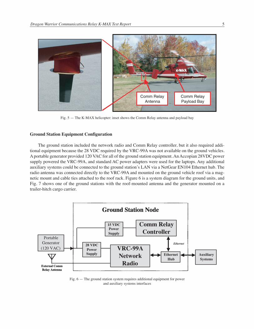
The ground station included the network radio and Comm Relay controller, but it also required addi-tional equipment because the 28 VDC required by the VRC-99A was not available on the ground vehicles.A portable generator provided 120 VAC for all of the ground station equipment. An Accopian 28VDC powersupply powered the VRC-99A, and standard AC power adapters were used for the laptops. Any additionalauxiliary systems could be connected to the ground station’s LAN via a NetGear EN104 Ethernet hub. Theradio antenna was connected directly to the VRC-99A and mounted on the ground vehicle roof via a mag-netic mount and cable ties attached to the roof rack. Figure 6 is a system diagram for the ground units, andFig. 7 shows one of the ground stations with the roof-mounted antenna and the generator mounted on atrailer-hitch cargo carrier.
Comm Relay Antenna
Comm Relay Payload Bay
Comm Relay Antenna
Comm Relay Payload Bay
Fig. 5 — The K-MAX helicopter; inset shows the Comm Relay antenna and payload bay
External Comm Relay Antenna
Ethernet
Ground Station Node
AuxiliarySystems
VRC-99ANetwork
Radio
28 VDC Power Supply
Comm Relay Controller
Portable Generator
(120 VAC)
Ethernet Hub
15 VDC Power Supply
External Comm Relay Antenna
Ethernet
Ground Station Node
AuxiliarySystems
VRC-99ANetwork
Radio
28 VDC Power Supply
Comm Relay Controller
Portable Generator
(120 VAC)
Ethernet Hub
15 VDC Power Supply
Fig. 6 — The ground station system requires additional equipment for powerand auxiliary systems interfaces

Tate, Kapuschansky, and Wood6
To provide maximum portability, a transit case with integral equipment rack was used for mounting allthe ground station equipment. Figure 8 shows the equipment configuration with the locations of the radio,the power supply, and the laptop computer identified. The cabling for the laptop computer had sufficientslack to allow it to be used from the front seat of the vehicle with the equipment rack located in the rear.
Test Procedures
Test and Analysis Software
We used NRL’s MGEN (Multi-Generator), a real-time scripted TCP/IP traffic generator to create datastreams (called flows) from all three nodes. Each test generated six flow rates to create dynamic networktraffic. MGEN generates time-stamped, sequenced packets with embedded real-time GPS information foreach node. The ground stations received their GPS data from Motorola M12 GPS units, and the airborne unitreceived its GPS information from the remote management system (RMS). Under normal Dragon Warrior
Comm relay controller and data acquisition laptop
AN/VRC-99A radio
28 VDC power supply
Portable equipment rack & transit case
Comm relay controller and data acquisition laptop
AN/VRC-99A radio
28 VDC power supply
Portable equipment rack & transit case
Fig. 8 — The ground station equipment, mounted in a portable transit case, included the AN/VRC-99A radio,the Comm Relay Controller laptop, and a power supply
Portable generator on trailer-hitch cargo carrier
Roof-mounted antenna
Portable generator on trailer-hitch cargo carrier
Roof-mounted antenna
Fig. 7 — The ground station had a roof-mounted antenna and a portablegenerator mounted on a trailer-hitch cargo carrier to provide power

Dragon Warrior Communications Relay K-MAX Test Report 7
operation, the airborne relay would not be a source of traffic, but for these tests we wanted a completepicture of traffic for all links, so the airborne node generated and recorded data just as the ground nodes did.
Received packet data were logged at all three nodes by DREC (Dynamic Receiver), NRL’s TCP/IPtraffic receiver/logger. DREC not only permits real-time display of the data for performance monitoring, butalso records data for post processing analysis. Our real-time displays showed received data throughput, butother network performance parameters (such as packet loss or latency) can also be displayed or processedoff-line. Each of the log files created by DREC represents the network activity as seen by the receiving node,and the entire test can be replayed from any node’s perspective for post processing. Each node transmittedflows not only to the other two nodes, but also to itself. With this approach, each node’s DREC log file storedthe received traffic from the other nodes along with its own GPS data. The files contained location informa-tion not only for the remote nodes, but also for the local node, even when no network connectivity exists.
To display the network performance graphically, NRL’s TRPR (Tcpdump Rate Plot Real Time) pro-vided data filtering and formatting to create plots using GnuPlot. The plots showed data throughput as afunction of time for all three flows being received at each node.
JMap, NRL’s moving map application, provided a real-time display of the vehicle locations. The ve-hicle locations were shown with a cross-hair indicator and text label listing the node name with a back-ground coloring scheme to show good (green), marginal (yellow), and lost (red) connectivity. A side-barindicator showed the GPS fix status as either valid (green), or invalid (gray). Figure 9 is an example of theJMap display during one of the tests with the Dragon3 node showing marginal connectivity, and Dragon1and Dragon2 nodes with good connectivity.
All of the software tools used for these tests are available for downloading from the following sites:
MGEN/DREC Toolset http://manimac.itd.nrl.navy.mil/MGENTRPR http://manimac.itd.nrl.navy.mil/ToolsJMap http://pf.itd.nrl.navy.mil.
Fig. 9 — The JMap program displayed moving icons that showed theposition of each vehicle, and provided a color-coded network statusindicator

Tate, Kapuschansky, and Wood8
Network Configuration
When the Comm Relay is used operationally, each of the ground stations will be connected to its ownLAN subnet, and the VRC-99A radio will serve as the router/gateway for each of those subnets. All of thetactical computer systems on the LAN (as represented by the Auxiliary Systems in Fig. 6) would be part ofthe subnet. The airborne subnet would have only the VRC-99A and the Comm Relay Controller as mem-bers, since no additional tactical computers would be on the DW aircraft. The VRC-99A radios also connectto an over-the-air (OTA) network that is separate from the other subnets. The radios belong to both the OTAsubnet and the local LAN subnet, and function as the router between the two subnets.
Figure 10 is a functional diagram of the network configuration that was used for the tests. Subnet1 (withIP addresses 192.168.1.X) resided on Ground Station 1 and comprised Dragon1 (the Comm Relay Control-ler laptop), the Router1 Ethernet interface to the VRC-99A, and any ancillary equipment connected throughthe Ethernet hub. Subnet3 (with IP addresses 192.168.3.X) was similarly configured on Ground Station 3.Subnet2 (with IP addresses 192.168.2.X) had only Dragon2 and Router2 connected to the radio. The OTAinterfaces on the radios (i.e., OTA1, OTA2, and OTA3) were members of the OTA subnet (with IP addresses128.1.0.X). We used standard IP subnet masking; in our case, this means that no member of a subnet wouldoperate in any other subnet without changing its IP address. All communication between the subnets wasrouted via the radios through the OTA subnet.
Radio Configuration
For our tests, the VRC-99A radios were used in the single-frequency mode at 1412 MHz, with an RFoutput power of 10 W. Of the 32 time-division multiple-access (TDMA) slots available, 8 were assigned toeach of the ground stations, and 16 were assigned to the airborne node.
Fig. 10 — The network configuration for the test comprised two ground station subnets,an airborne subnet, and an over-the-air (OTA) subnet
OTA3128.1.0.3
Router3192.168.3.1
OTA1128.1.0.1
Router1192.168.1.1
OTA2128.1.0.2
Router2192.168.2.1
Dragon3192.168.3.2
Dragon1192.168.1.2
Dragon2192.168.2.2
802.3 Ethernet
Over The Air Network
Remote Management
System
RS-232
GPS
RS-232
GPS
VRC-99A Radio
Laptop Computer
EthernetHub
EthernetHub
OTA3128.1.0.3
Router3192.168.3.1
OTA3128.1.0.3
Router3192.168.3.1
OTA1128.1.0.1
Router1192.168.1.1
OTA1128.1.0.1
Router1192.168.1.1
OTA2128.1.0.2
Router2192.168.2.1
OTA2128.1.0.2
Router2192.168.2.1
Dragon3192.168.3.2
Dragon3192.168.3.2
192.168.3.XDragon1
192.168.1.2Dragon1
192.168.1.2
Subnet1192.168.1.X
Dragon2192.168.2.2
Dragon2192.168.2.2
Subnet2192.168.2.X
802.3 Ethernet802.3 Ethernet
Over The Air NetworkOver The Air Network
OTA Subnet128.1.0.X
Remote Management
System
RS-232
GPS
RS-232
GPS
VRC-99A RadioVRC-99A Radio
Laptop ComputerLaptop Computer
EthernetHub
EthernetHubRS-232
Subnet3
Ground Station Ground Station
AirbornePlatform

Dragon Warrior Communications Relay K-MAX Test Report 9
Scripts
Each of the tests involved running multiple programs on all nodes; to simplify this process, scripts werewritten for each node. A common script was used to start each test, but the script was able to determine fromwhich node it was executed, and ran the appropriate programs for each node. The MGEN and DREC pro-grams were run on all nodes, but the flow designators were tailored to reflect the source and destination nodenumbers. TRPR, Gnuplot, and JMap did not run on the airborne unit, since there was no operator to view thedisplays. At the completion of each test, another script was executed to stop the test, which terminated theappropriate processes and copied the log file to an archive file.
Because of the variability of preflight preparation, locations of the ground stations, and flight times forthe various sorties, the scripts on each node were not guaranteed to be started at exactly the same time. Allscripts were started within several minutes of each other, and since the data included time stamps for allpackets, registration of events with clock time was possible.
3. TEST RESULTS
Ground-to-Ground Test
The objective of this test was to determine usable range between ground vehicles with no airborne relay.The ground-to-ground test was performed near Kaman headquarters in Bloomfield, CT. The terrain in thisarea can be characterized as a hilly wooded suburban community. Clear line of sight between ground ve-hicles is difficult to obtain in this terrain, and blockage due to foliage and buildings is a major factor.
The test setup comprised one stationary vehicle with a second mobile vehicle following radial patternsemanating outward from the fixed node’s position. Figure 11 shows the area of the tests, with the stationaryvehicle positioned in the center, and flags positioned at locations where the signal was lost (when the mobilevehicle was moving away from the stationary vehicle), or where the signal was recovered (when movingtoward the stationary vehicle). A circle with a 1-mi radius from the stationary node is drawn for reference.
The results of this test showed that the maximum achievable range was consistently less than 1-mi.Even though the radios were transmitting at 10 W, the foliage, terrain, and nearby buildings significantlyblocked the VRC-99A’s 1.4 GHz radio signals. Under these conditions, it is apparent that an airborne relayis necessary to provide connectivity between these radios, even at close range.
Short-Range Low-Altitude Test
While the aircraft was performing targeting and mapping tests for the EO/IR payload, we took theopportunity to collect communications data, even though the aircraft was not being operated at the CommRelay mission altitude. The purpose of collecting data under these conditions was to determine the feasibil-ity of using an airborne relay operating at low altitudes. While the aircraft was performing its targeting andmapping functions near the Mountain Meadow Airstrip, our mobile ground node drove along nearby roadsto collect connectivity data. Figure 12 shows that under these conditions, the connectivity between theaircraft and the mobile unit (shown by the purple line) was very sparse compared to the actual path followedby the ground vehicle (shown by the green line). Connectivity was achieved for less than half of the time ofthe test. Nearby foliage and the hilly terrain of this area created significant blockage. Because of the rela-tively short distance to the aircraft (typically less than 10 mi), it was not difficult to predict when outageswould occur as we proceeded along the roads between the hills. The signal would typically be recoveredwhen the mobile unit moved into an area where it had a clear view of the sky in the direction of the aircraft.

Tate, Kapuschansky, and Wood10
Fig. 11 — The ground-to-ground tests were performed around a centralstationary vehicle within a 1-mi radius (shown as a red circle)
Fig. 12 — A comparison of the mobile ground vehicle actual path (green line) and the areas ofconnectivity to the aircraft (purple line) shows that foliage and terrain caused significant blockagewhen the K-MAX was operating below the Comm Relay mission altitude.
2
miles
4 6 8 100 2
miles
4 6 8 100 2
miles
4 6 8 100

Dragon Warrior Communications Relay K-MAX Test Report 11
The conditions of this test were such that terrain caused significant blockage because the aircraft wasusually not high enough to provide clear line of sight to the ground vehicle. The implication is that the low-altitude requirement for targeting missions is unsatisfactory for Comm Relay missions. Without sufficientaltitude to provide clear line of sight (LOS) to the ground stations, the Comm Relay cannot provide adequatecoverage in this type of terrain.
Long-Range Over-Seawater Test
The objective of this test is to collect performance measurements when the air vehicle is over seawaterand the ground vehicles are located ashore. Multipath effects due to RF reflections from seawater are ex-pected to contribute to performance differences. This test simulates the performance of the network whenDW is launched from a Navy ship in support of Marines ashore.
The flight conditions were such that the aircraft was to maintain as close to the 6000-ft mission altitudewhenever possible. Weather and FAA restrictions limited actual altitudes to 4500 to 5500 ft. The flight pathsfollowed the two sorties described in Section 2. The ground stations were stationary on Talcott Mountain(890-ft elevation) and at Lighthouse Point (40-ft elevation) for Sortie 1, then on Talcott Mountain and atShort Beach (10-ft elevation) for Sortie 2. From these locations, the aircraft would reach a distance of morethan 50 nmi over land from Talcott Mountain, and more than 50 nmi over water from Lighthouse Point andShort Beach.
Sortie 1
For the first sortie, the flight path (shown in Fig. 1) began at Kaman headquarters, went past TalcottMountain, past Lighthouse Point, to Block Island, and returned by retracing the same path. Talcott Mountainprovided a good “high ground” vantage point for maintaining long LOS over much of the terrain. Light-house Point provided a good vantage point over water to the south. However, as we discovered during thistest, the view to the east (which is the direction the flight path followed) was obscured by a nearby tree line.Figure 13 shows the connectivity between the K-MAX aircraft and the ground station at Talcott Mountain asa yellow line, and connectivity between the K-MAX and the ground station at Lighthouse Point is shown inpurple. Areas where the yellow and purple lines are adjacent to each other is where the airborne nodefunctions as a relay between the two ground stations.
The figure shows that as the K-MAX proceeded from Kaman headquarters toward Lighthouse Point,the Talcott Mountain ground station had good connectivity but the Lighthouse Point location was masked bythe terrain to its north. As the K-MAX reached the area approximately 15 miles north of Lighthouse Point,the ground station there began to communicate with the K-MAX and a relay was established (at position(1)). As the K-MAX approached the area near Lighthouse Point, it descended to 1500 ft, at which time LOSand connectivity to Talcott Mountain was lost. After passing Lighthouse Point, the K-MAX turned east tobegin its overwater path along Long Island Sound and resumed its planned flight altitude, which restored theconnectivity to Talcott Mountain (at position (2)). Lighthouse Point maintained connectivity to the aircraftuntil it was 34 mi away (at position (3)), at which time the local tree line at Lighthouse Point obscured itsLOS. Connectivity to Talcott Mountain was intermittent for the remainder of the outbound flight because ofthe local mountains and ridge lines between Talcott Mountain and Long Island Sound. The local mountainsobscured portions of the flight path from the Talcott Mountain location because, although the K-MAX was4000 to 5000 ft high, at the maximum range of 65 mi (at location (4)) the direct LOS to the aircraft was lessthan one degree above the horizon.

Tate, Kapuschansky, and Wood12
On the return leg, the Lighthouse Point location did not regain connectivity with the K-MAX, appar-ently because the fuselage masked the antenna on the aircraft. The K-MAX was flying into the wind for thisleg, causing it to assume a nose-down attitude, further contributing to the masking problem. At location (5),Talcott Mountain regained connectivity to the K-MAX and maintained it until the end of the flight.
Because of the lack of good LOS over 50 nmi of water from the Lighthouse Point location, the groundstation was moved to Short Beach for the second sortie.
Sortie 2
For the second sortie, the flight path (see Fig. 1) began at Kaman headquarters, went past Talcott Moun-tain, to the vicinity of Short Beach, to Fishers Island, and returned by retracing the same path. Figure 14shows the connectivity between the K-MAX aircraft and the ground stations for Sortie 2.
The second sortie provided some results that were consistent with the results of the first sortie, and someresults that were improvements in performance. As with the first sortie, good connectivity was quicklyestablished and maintained with the Talcott Mountain ground station. For this sortie, however, the K-MAXmaintained high enough altitude to serve as a good relay to the Short Beach location (at (1)). When theaircraft started traveling eastward, connectivity was intermittent to Talcott Mountain but consistently wasreliable to Short Beach (at (2)). Signal blockage by the mountains between Long Island Sound and TalcottMountain were the major cause of drop-outs to that ground station. The Short Beach ground station hadgood connectivity, with only occasional breaks until the aircraft began its return path near Fishers Island (at(3)). Note that as the K-MAX began its return trip, it was communicating with both Talcott Mountain (at a
Kaman Headquarters
Mountain Meadow Airstrip
Short Beach
Lighthouse Point
Block Island
Fishers Island
Talcott Mtn.
0 10 20 30 40 50miles
Connectivity Legend
K-MAX to Talcott Mtn.K-MAX to Lighthouse Pt.Relay through aircraft
1
2 3 4
5
Kaman Headquarters
Mountain Meadow Airstrip
Short Beach
Lighthouse Point
Block Island
Fishers Island
Talcott Mtn.
Kaman Headquarters
Mountain Meadow Airstrip
Short Beach
Lighthouse Point
Block Island
Fishers Island
Talcott Mtn.
0 10 20 30 40 50miles
0 10 20 30 40 50miles
Connectivity Legend
K-MAX to Talcott Mtn.K-MAX to Lighthouse Pt.Relay through aircraft
Connectivity Legend
K-MAX to Talcott Mtn.K-MAX to Lighthouse Pt.Relay through aircraft
1
2 3 4
5
Fig. 13 — Connectivity between the K-MAX and the two ground stations during Sortie 1shows the masking effects of the terrain

Dragon Warrior Communications Relay K-MAX Test Report 13
distance of 55 mi) and Short Beach (at a distance of 60 mi) and functioning as a relay between the two. Thisshows that with good LOS, the Comm Relay will be able to meet the target range requirements.
As soon as the K-MAX began its return trip, it again assumed a nose-down attitude to compensate forhead winds. This again caused the antenna on the tail of the aircraft to be masked by the fuselage from bothground stations. The long range to the aircraft weakened the signal, which also contributed to the drop-out.On the return trip, the K-MAX altitude was increased to 5500 ft, which contributed to the signal beingrecovered (at (4)) by both ground stations, although antenna masking was still evident from the Short Beachlocation.
As the K-MAX turned northward, the antenna was no longer masked from the Short Beach location andconnectivity was restored, but the Talcott Mountain location was now masked. This condition continueduntil the terrain blocked the LOS from Short Beach, causing loss of connectivity (at (6)). Shortly afterward,the K-MAX was close enough to Talcott Mountain to overcome the masking, and connectivity was main-tained for most of the remainder of the test.
Network Throughput Measurements
Data throughput vs time plots were displayed to monitor the behavior of the network. Figure 15 showsthe throughput plot for data received at the Talcott Mountain ground station. The red trace is the data fromTalcott Mountain, the green trace is data from the K-MAX, and the blue trace is data from the Short Beachlocation. The dotted lines show the data rates that are actually transmitted at the source. The red trace on thisfigure represents locally generated data that are not transmitted by the radio.
Kaman Headquarters
Mountain Meadow Airstrip
Short Beach
Lighthouse Point
Fishers Island
Talcott Mtn.
Block Island
0 10 20 30 40 50miles
Connectivity Legend
K-MAX to Talcott Mtn.K-MAX to Short BeachRelay through aircraft
1
2
34
5
6
Kaman Headquarters
Mountain Meadow Airstrip
Short Beach
Lighthouse Point
Fishers Island
Talcott Mtn.
Block Island
Kaman Headquarters
Mountain Meadow Airstrip
Short Beach
Lighthouse Point
Fishers Island
Talcott Mtn.
Block Island
0 10 20 30 40 50miles
0 10 20 30 40 50miles
Connectivity Legend
K-MAX to Talcott Mtn.K-MAX to Short BeachRelay through aircraft
Connectivity Legend
K-MAX to Talcott Mtn.K-MAX to Short BeachRelay through aircraft
1
2
34
5
6
Fig. 14 — Connectivity between the K-MAX and the two ground stations during Sortie 2shows the masking effects of the terrain and the aircraft fuselage

Tate, Kapuschansky, and Wood14
Fig. 15(a) — Throughput measurements for data received at Talcott Mountain shows the intermittent connectivity to both the airborne node (green) and the other ground node (blue)
Fig. 15(b) — A close-up of the throughput measurements shows details of the variation in network traffic

Dragon Warrior Communications Relay K-MAX Test Report 15
The figure shows that there were some periods of good connectivity (such as where a solid line closelyfollows the corresponding dotted line), some periods of marginal connectivity (where the solid line variessignificantly from the dotted line), and periods of no connectivity (where the solid line is zero). The varia-tions in the solid line, which seem to indicate that the data are being received faster than they are beingtransmitted, are caused by the buffering mechanism in the radio. When transmission errors occur, the radiorepeats the transmission in a best-effort attempt to provide reliable data transfers. The radio buffers the datauntil either the data are received or the buffer overflows, at which point some data are discarded. When theradio transmits a large amount of data that is stored in its buffer, the instantaneous data rate can actuallyexceed the data rate being generated by the source alone. For UDP packets (which is the protocol we usedfor this test), a buffer overflow condition causes the packets to be simply dropped. For TCP packets (theguaranteed delivery protocol used for most Internet connections), an error condition is sent to the applica-tion program. For our tests, we chose to use UDP packets to prevent excessive buffer overflow and time-outerrors that are likely to occur with TCP packets in this environment. The number of lost packets is one of themetrics that can be retrieved from the DREC log files for post-analysis.
Another feature of the plot that is not obvious is the fact that the blue trace is only nonzero when thegreen trace is nonzero. This is because Talcott Mountain did not have direct connectivity to Short Beach(blue), and could only receive Short Beach data through the K-MAX relay (green). The converse were nottrue, however. The green trace is nonzero in some areas where the blue trace is zero. This is because the datawere being received from the K-MAX, but the network relay function has been temporarily suspendedbecause of the loss of the link to Short Beach.
Figure 16 shows the same data from the perspective of the Short Beach ground station. On this figure,the local data are now the blue trace, and the remote ground station data are the red trace. This figure showsthe same general behavior as the previous figure, but the buffering mechanism is even more evident. Notethat there are more spikes in the data rate above 80 kbps and a few above 100 kbps. This indicates that thechannel has intermittent drop-outs, but the drop-outs are not sufficient in length to cause packets to bediscarded. The buffer is more nearly full, and quick bursts of large amounts of data manifest themselves ashigh throughput values. Also note that now the red trace is only nonzero when the green trace is nonzero, forthe same reason that was described earlier.
AN/VRC-99A Radio Operation
The VRC-99A radio is designed to provide backbone network service for networks of up to 16 radios.Although our network contained only three radios, the delays in start-up time and recovery of loss of signalwere excessively long, and may be problematic when trying to use these units in field exercises. During ourtests, we often questioned whether the radios were functioning properly based on what we observed on thefront panel indicators and what we saw in our test software. It was typical for the receive indicator on thefront panel of the radio to begin blinking up to a minute before network connectivity was achieved. Underconditions where connectivity was intermittent, the receive indicator would blink for a short time then stop,without ever regaining connectivity to the network.
We performed some basic bench tests to get some quantitative measurements on start-up times, signalloss, and recovery timing. From power-up, it took approximately three minutes for the radio to begin pro-cessing network traffic. We found that for any loss of signal (10 dB below the radio sensitivity) for morethan 15 seconds, it takes 50 to 60 seconds for the VRC-99A to resume normal network traffic. Delays thislong would be unacceptable for Marine Corps use during very mobile operations that might require intermit-tent loss of LOS to the Comm Relay.

Tate, Kapuschansky, and Wood16
Fig. 16 — Throughput measurements show a different network behavior fordata received at the Short Beach ground station

Dragon Warrior Communications Relay K-MAX Test Report 17
BAE Systems was contacted regarding this apparent problem with the VRC-99A. The start-up timeincludes the built-in test (BIT) time of approximately two minutes, and a Listen Mode time of approxi-mately one minute. During the Listen Mode, the radio waits to receive data from other radios to determineits TDMA timing. If no other radios are detected, it begins transmitting to initiate network traffic. Once thenetwork is established, the radio should not enter Listen Mode again unless it receives no signal for at leastfive minutes. Any shorter loss of signal should be recovered from in less than 10 seconds.
Our radios seem to enter the Listen Mode after only 15 seconds of lost signal. BAE has indicated thatthis is not the expected behavior of these radios, and further analysis of the problem is necessary. Thesoftware version of our radios (V1.0) is not the most recent (V1.2), but that was not identified as the sourceof the problem. As of the date of this report, they have not provided a solution, and this issue remainsunresolved.
4. CONCLUSIONS
We can draw several conclusions from these tests. First, the VRC-99A requires clear line-of-sight tooperate, even for relatively short distances. Both the ground-to-ground test and the low-altitude test con-firmed this. Significant signal blockage due to terrain, foliage, and buildings was observed, and avoidingthese obstacles is an important operational consideration. This is typical behavior for radios operating in theL-Band (and higher) frequency range. Maintaining the Comm Relay mission altitude of 6000 ft (or higher)is important for providing good LOS.
Another important conclusion is that the target Comm Relay range of 50 nmi from the aircraft is achiev-able at the 6000-ft mission altitude, both over land and over seawater. During our long-range test, twoground stations separated by 48 mi were able to relay through the airborne node, which was 55 to 60 mi fromboth of them. Supporting ground units with a Comm Relay located 50 mi away can provide a significanttactical advantage. One of our secondary objectives was to determine whether multipath over seawaterwould adversely affect performance. However, we had no method to measure it directly, and we saw noevidence of it in our data.
Antenna masking by the air vehicle fuselage was significant during our tests, but this problem wasspecific to the particular air vehicle that was being used and where the antenna was located. On the K-MAX,the antenna was located aft of the fuselage and the aircraft assumed a nose-down attitude while flying. Thesecombined to create significant masking when viewed from the front of the vehicle. This effect is expected tobe negligible on the Dragon Warrior vehicle because it is designed to fly level, and the antenna will belocated on the lowest part of the vehicle (excluding the landing gear). We will investigate antenna maskingin our analysis and design of the antenna system for the DW prototype.
Operational use of the VRC-99A proved to be more complicated than we expected. It may prove to beunacceptable for the kind of mobile operations in which the Marine Corps would need them. Start-up andsignal acquisition times were unreasonably long for the kind of dynamic environment in which they wouldbe used. Observing the front panel indicators provided little help in determining the status of the networktraffic, and at times the indicators were misleading. We will continue to work with BAE Systems to correctthe problems and upgrade the software in the radio to provide the kind of quick response and transparentfunctionality that a high-data-rate network radio should have.

Tate, Kapuschansky, and Wood18
5. FOLLOW-ON EFFORTS
Since the conclusions of these tests, improvements have been made to the operational characteristics ofthe radio and to the methods of performing configuration management.
Radio Performance Improvements
The VRC-99A is a major component of the JTF WARNet program, and extensive laboratory and fieldtesting has uncovered additional areas of improvement for the radio. The WARNet program is the conduitthrough which the VRC-99A will be transitioned from a developmental prototype to a deployed joint net-work communications asset.
The problems that we experienced with long recovery times after loss of signal have been corrected inlater versions of the radio firmware. The link quality filter controls the rate at which the radios loses orreestablishes links. The original design used fixed parameters based on early system design specificationsthat are now obsolete. The new firmware not only allows the filter parameters to be changed, but the newdefault settings provide much better performance for a highly mobile user environment. Delays seen duringour tests of typically one minute are now reduced to about ten seconds with the new parameters.
JTF WARNet has initiated improvements to radio functions that were not exercised in our test. The sizeand complexity of the WARNet architecture has led to additional performance enhancements. These en-hancements include link quality filter improvements, adaptive slot allocation, improved OSPF performance,IP bridging, and quality of service (QOS).
Configuration Management Improvements
We have made changes to the Comm Relay Controller (CRC) to allow configuration management to behandled through a Web browser, thereby making the user interface platform-independent. Users withJavaScript-enabled browsers such as Netscape, Opera, or Internet Explorer can access the CRC from theirPC, Macintosh, or Linux computer.
The new CRC hardware is a 5X86 133 MHz embedded Linux processor in a PC-104 form factor thatruns a Web server with pages for checking radio status, creating, modifying, and uploading configurationfiles, and configuring the radio. The Web pages can be accessed from anywhere on the network throughsimple password-protected access controls. Special attention has been taken to eliminate the need for usersto know the specific syntax required by the radio interface. Anyone with a general understanding of theoperation of the radio and the configuration of the network to which it is connected will have no difficultyusing the Web pages. Figure 17 shows a portion of the page that allows the user to create a configuration file.It uses familiar graphical interface controls such as check boxes, pull-down lists, and text areas for enteringthe radio parameters. Configuration checking functions display alerts for invalid conditions, thereby pre-venting the user from unknowingly entering conflicting parameters. Multiple configuration files can becreated or uploaded to support multiple missions, frequency management restrictions, or test scenarios.
The JTF WARNet program is also adapting a Web-based configuration management approach. TheirSystems Management Web Server will also include a database to maintain configuration and status informa-tion for all the radios in the joint network, to support their more extensive and detailed network managementand monitoring requirements.

Dragon Warrior Communications Relay K-MAX Test Report 19
Comm Relay Payload
The Comm Relay Payload nose cone has been built and tested in the laboratory. Figure 18 is a sketch ofthe Comm Relay components comprising the VRC-99A, Comm Relay Controller, and antenna. The addi-tional Inertial Navigation System and compass components are required by the aircraft avionics. Initialflight demonstration of the aircraft is scheduled for November 2002.
Field Testing
The Comm Relay Payload development will continue through FY03, with an emphasis on field testing.Testing will be performed at NRL’s test flight facilities and, as required, as part of upcoming military exer-cises. Current plans include the first demonstration of the Comm Relay in a military exercise as part of theJTF WARNet Predeployment Exercise (PDX).
Fig. 17 — The CRC Web server provides configuration management through pagessuch as this “Create Configuration File” page

Tate, Kapuschansky, and Wood20
6. SUMMARY
These tests have proven to be an overall success in that we have accomplished our goals and learnedsome important lessons about the network radios and the expected performance of the Dragon WarriorCommunications Relay. Close coordination with the JTF WARNet program has provided important perfor-mance information. This information has contributed to improvements in the radio that will benefit the jointmilitary forces. Field tests will be conducted to confirm that the Dragon Warrior Communications Relaywill provide the type of networked data communications required by tomorrow’s warfighters.
Fig. 18 — The Comm Relay Payload is a modular, replaceable nose conefor the Dragon Warrior unmanned air vehicle
Inertial NavigationSystem (INS)
CompassComm RelayController (CRC)
AN/VRC-99ANetwork Radio
Antenna

Dragon Warrior Communications Relay K-MAX Test Report 21
Appendix
EQUIPMENT PHYSICAL SPECIFICATIONS AND INTERFACES
Network Radio: BAE Systems VRC-99A (3 each, 2 ground, 1 airborne)Airborne Antenna: Trivec Avant AV237-8 (1 each)Ground Vehicle Antenna: Antenna Products DPV-49N (2 each)Airborne Comms Host: Hewlett Packard Toughbook 27 (1 each)Ground Comms Host: Toshiba Satellite Pro 470CDT (2 each)Ethernet Hub: Netgear EN104NA (2 each)DC-DC Converter: VICOR MI-LC22-IW (1 each)
Network Radio
Type: BAE Systems VRC-99APrimary Power: 28 VDC, 140 WWeight: 30 lbSize: 3/4 ATR Short, 7.62-in. H ¥ 7.5-in. W ¥ 12.62-in. D (w/o handles)802.3 port: Ethernet 10Base2 BNCAntenna Port: Type NFrequencies: 1308-1484 MHz, 2 bands, 19 channels, 8 MHz BW per channelOutput Power: 10 W maximumModulation: Direct sequence spread spectrum, 20 Mcps, half duplexChannel Access: 32 slot TDMA, 16 users, static allocationData Rates: 0.625, 1.25, 2.5, 5, and 10 MbpsThroughput: 8.5, 14.9, 40.8, 92.5, and 195.9 kbps per TDMA slot (max.)COMSEC: Type 1 Cryptography available (Crypto Bypass Modules were used
for these tests and equipment was UNCLASSIFIED)Airborne Antenna
Type: Trivec Avant AV237-8Input Port: Type N
Ground Vehicle Antenna
Type: Antenna Products DPV-49NInput Port: Type N
Airborne Comm Relay Controller
Type: Toshiba Satellite Pro 470CDTPrimary Power: 15 VDC, 3 AWeight: 7.75 lbSize: 9.5-in. L ¥ 12.0-in. W ¥ 2.5-in. H
21

Tate, Kapuschansky, and Wood22
Ground Station Comm Relay Controller
Type: Toshiba Satellite Pro 470CDTPrimary Power: 15 VDC, 3 AWeight: 7.75 lbSize: 9.5-in. L ¥ 12.0-in. W ¥ 2.5-in. H
Ethernet Hub
Type: Netgear EN104NAPrimary Power: 7.5 VDC, 1 AWeight: 0.74 lbSize: 4.0-in. L ¥ 3.7-in. W ¥ 1.1-in. H10Base2 port: BNC10BaseT ports: RJ-45 (4 ea.)
DC-DC Converter
Type: Automated Business Power ABP-36V/ADJ/20AInput: 28 V DC (from generator)Output: 12 V DC (for Airborne Host, and Ethernet Hub)Weight: 1.4 lbSize: 4.5-in. L ¥ 3.5-in. W ¥ 2.1-in. H