Drag Conveyor...• Handling foodstuff subjects conveyors to special codes for construction,...
32
Part Number: DCM0308-R1 Revised: May/11 Read this manual before using product. Failure to follow instructions and safety precautions can result in serious injury, death, or property damage. Keep manual for future reference. NORTH AMERICAN VERSION - ORIGINAL INSTRUCTIONS DRAG CONVEYOR COMMERCIAL MODELS ASSEMBLY & OPERATION
Transcript of Drag Conveyor...• Handling foodstuff subjects conveyors to special codes for construction,...
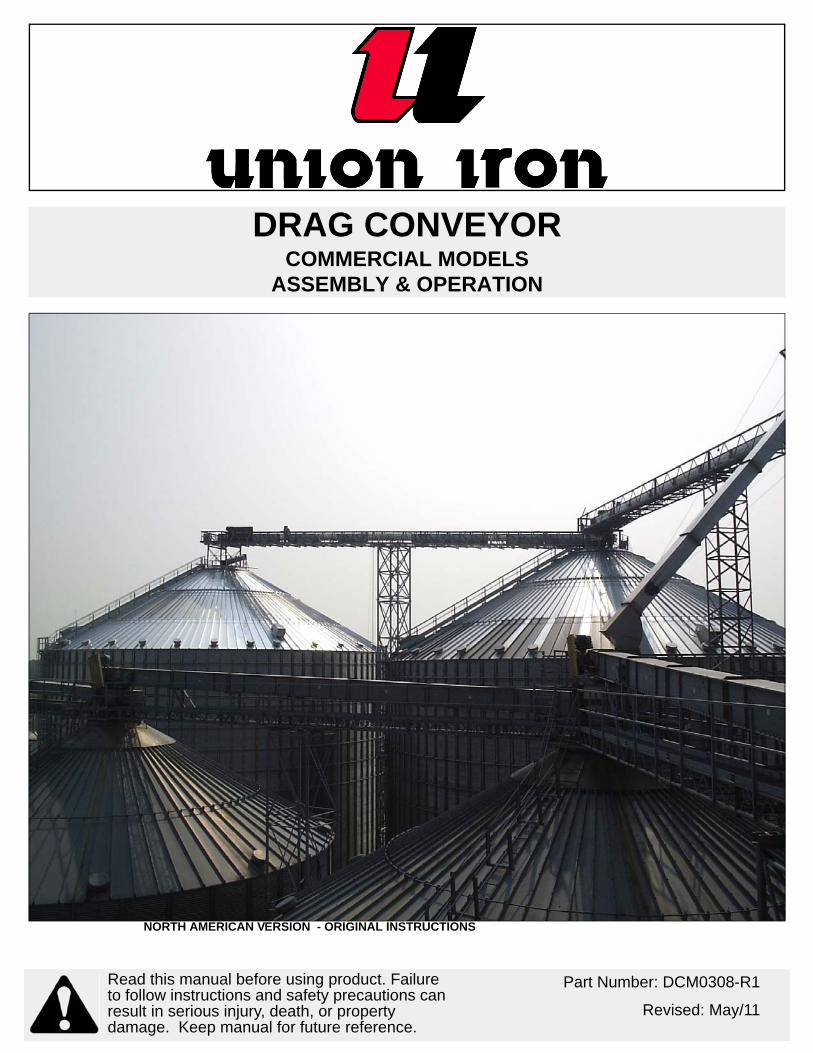
NORTH AMERICAN VERSION - ORIGINAL INSTRUCTIONS
DRAG CONVEYORCOMMERCIAL MODELS
ASSEMBLY & OPERATION
Part Number: DCM0308-R1
Revised: May/11
Read this manual before using product. Failure to follow instructions and safety precautions can result in serious injury, death, or property damage. Keep manual for future reference.

This product has been designed and constructed according to general engineering standardsa. Other local regulations may apply and must be followed by the operator. We strongly recommend that all personnel associated with this equipment be trained in the correct operational and safety procedures required for this product. Periodic reviews of this manual with all employees should be standard practice. For your convenience, we include this sign-off sheet so you can record your periodic reviews.
a. Standards include organizations such as the American Society of Agricultural and Biological Engineers, American National Standards Institute, Canadian Standards Association, International Organization for Standardization, and/or others.
Date Employee Signature Employer Signature

TABLE OF CONTENTS
UNION IRON - DRAG CONVEYOR COMMERCIAL MODELS
1. Introduction .......................................................................................................................... 5
2. Safety First............................................................................................................................ 72.1. General Safety ......................................................................................................... 82.2. Assembly Safety....................................................................................................... 92.3. Operational & Maintenance Safety........................................................................ 10
2.3.1. Lockout and Tagout Procedures .............................................................. 102.4. Electric Motor Safety .............................................................................................. 112.5. Safety Decal Locations........................................................................................... 11
2.5.1. Decal Installation ...................................................................................... 112.5.2. Decal Locations ........................................................................................ 11
3. Installation .......................................................................................................................... 133.1. Shipping Check ...................................................................................................... 133.2. Lifting and Moving .................................................................................................. 133.3. Assembly................................................................................................................ 133.4. Installation .............................................................................................................. 143.5. Installation for Torque-Arm II Speed Reducer........................................................ 15
3.5.1. Torque-Arm II Bushing Installation ........................................................... 17
4. Operation ............................................................................................................................ 214.1. Pre-Operation......................................................................................................... 214.2. Start-Up .................................................................................................................. 214.3. General................................................................................................................... 22
5. Maintenance ....................................................................................................................... 235.1. Projected Chain Conveyor Maintenance................................................................ 245.2. Torque-Arm II Speed Reducer Maitenance............................................................ 24
5.2.1. Bushing Removal for Standard Taper Bushings ...................................... 245.2.2. Lubrication ................................................................................................ 25
5.3. Drag Conveyor Extended Shutdown/Storage ........................................................ 265.4. Torque-Arm II Speed Reducer Storage.................................................................. 27
6. Troubleshooting ................................................................................................................. 29
Limited Warranty ..................................................................................................................... 31
DCM0308-R1 3

UNION IRON - DRAG CONVEYOR
COMMERCIAL MODELS
4 DCM0308-R1

UNION IRON - DRAG CONVEYOR 1. INTRODUCTION
COMMERCIAL MODELS
1. IntroductionUnion Iron Works Drag Conveyors are tough, dependable, and provide efficient handling capacity for conveying a wide variety of bulk materials with minimum product degradation.
The flat bottom design increases conveying capacity, and special Union Iron features substantially reduce the product-to-product contamination that you find with other designs. Product features include:
• Rugged, heavy-duty steel construction for durability in the most demand-ing applications.
• Dust and weather-tight construction to maintain product quality against the elements and prevent dust from escaping.
• UHMW polyethylene flights to reduce metal-to-metal contact and provide quiet, efficient operation.
• Replaceable bottoms and side liners.• Head and tail are equippped with removable end plates to facilitate main-
tenance.
Before using the Drag Conveyor, give this manual to the people who will be operating and maintaining this equipment. Reading and understanding the manual will reduce downtime and equipment failure, as well as ensure safe and efficient operation. A sign-off form is provided on the inside front cover for your convenience.
The serial number plates are located on the head assembly side plate on the opposite side of the drive, and on the tail assembly side plate. Please mark the number in the space provided for easy reference.
This operator’s manual should be regarded as part of the equipment. Suppliers of both new and second-hand equipment are advised to retain documentary evidence that this manual was provided with the machine.
Model#
Serial #
Production Year
DCM0308-R1 5

1. INTRODUCTION UNION IRON - DRAG CONVEYOR
COMMERCIAL MODELS
6 DCM0308-R1

UNION IRON - DRAG CONVEYOR 2. SAFETY FIRST
COMMERCIAL MODELS
2. Safety FirstThe Safety Alert symbol to the left identifies important safety messages on the product and in the manual. When you see this symbol, be alert to the possibil-ity of personal injury or death. Follow the instructions in the safety messages. Why is SAFETY important to you?
Three big reasons:
• Accidents disable and kill.• Accidents cost.• Accidents can be avoided.
SIGNAL WORDS
Note the use of the signal words DANGER, WARNING, CAUTION, and NOTICE with the safety messages. The appropriate signal word for each message has been selected using the definitions below as a guideline.
The Safety Alert symbol means: “ATTENTION, BE ALERT! YOUR SAFETY IS INVOLVED”.
DANGER
Indicates an imminently hazardous situation that, if not avoided, will result in serious injury or death.
WARNING
Indicates a hazardous situation that, if not avoided, could result in serious injury or death.
CAUTION
Indicates a hazardous situation that, if not avoided, may result in minor or moderate injury.
NOTICE
Indicates a potentially hazardous situation that, if not avoided, may result in property damage.
DCM0308-R1 7
2. SAFETY FIRST UNION IRON - DRAG CONVEYOR
2.1. GENERAL SAFETY COMMERCIAL MODELS
2.1. GENERAL SAFETY
Important: The general safety section includes instructions that apply to all safety practices. Any instructions specific to a certain safety practice (e.g., assembly safety), can be found in the appropriate section. Always read the complete instructional sections and not just these safety summaries before doing anything with the equipment.
YOU are responsible for the SAFE use and maintenance of your equipment. YOU must ensure that you and anyone else who is going to work around the equipment understands all procedures and related SAFETY information contained in this manual.
Remember, YOU are the key to safety. Good safety practices not only protect you, but also the people around you. Make these practices a working part of your safety program.
• It is the equipment owner and the operator's responsibility to read and under-stand ALL safety instructions, safety decals, and manuals and follow them before assembling, operating, or maintaining the equipment. All accidents can be avoided.
• Equipment owners must give instructions and review the information initially and anually with all personnel before allowing them to operate this product. Untrained users/operators expose themselves and bystanders to possible serious injury or death.
• Use this equipment for its intended purposes only.• Do not modify the equipment in any way. Unauthorized modification may
impair the function and/or safety, and could affect the life of the equipment. Any modification to the equipment voids the warranty.
• Do not allow children, spectators, or bystanders within the work area.• Have a first-aid kit available for use should the need arise, and know how to
use it.• Provide a fire extinguisher for use in case of an accident. Store in a highly vis-
ible place.• Wear appropriate protective gear. This list includes, but
is not limited to:• a hard hat• gloves• protective shoes with slip-resistant soles• protective goggles• hearing protection• dust mask or respirator
• For Powered Equipment: before servicing, adjusting, or repairing powered equipment, unplug, place all controls in neutral or off position, stop the engine or motor, remove ignition key or lock out power source, and wait for all mov-ing parts to stop.
8 DCM0308-R1
UNION IRON - DRAG CONVEYOR 2. SAFETY FIRST
COMMERCIAL MODELS 2.2. ASSEMBLY SAFETY
• Follow good shop practices:• keep service area clean and dry• be sure electrical outlets and tools are properly
grounded• use adequate light for the job at hand• Think SAFETY! Work SAFELY!
2.2. ASSEMBLY SAFETY
• Have 2 people handle the heavy, bulky components.• Check all equipment for damage immediately upon arrival. Do not attempt to
install a damaged item.• If the equipment must have an open housing as a condition of its use and
application, it must be guarded by a railing or fence.• Use rugged gratings where necessary. If the distance between the grating
and moving elements is less than 4”, the grating opening must not exceed 1/2” x 1” (or 1/2” x 2” for hopper gratings). Covers, guards, and gratings at inlet points must be installed so that personnel cannot be injured in any way.
• Use solid covers that are designed and installed so that personnel is not exposed to accidental contact with any of the equipment’s moving parts.
• Connect inlet and discharge openings to other equipment in order to com-pletely enclose the equipment.
• As required by the applicable laws, standards, and good practice, the pur-chaser/owner is responsible for:
• guarding all rotating equipment such as drives, gears, shafts, and cou-plings
• purchasing and providing safety devices and controls• Before power is connected to the drive, perform a pre-start-up safety check to
ensure the equipment and area is safe and that all guards are in place and secure.
• Electrical equipment must conform to the National Electric Code or National Electrical Safety Code, including requirements for the environment. Also con-sider:
• Overflow devices (electrical interlocks) to warn personnel and shut off power when discharge from conveyor is interrupted.
• Overload protection for devices (shear pins, torque limiters, etc.) and no-speed protection (zero-speed switches) to shut off power in the event of an incident that might cause the conveyor to stop operating.
• Safety shut-off switch with power lockout provisions at conveyor drive.• Emergency stop switches that are readily accessible.• Electrical interlocking to shut down feeding conveyors whenever a receiv-
ing conveyor stops.• Signal devices to warn personnel of imminent start up of conveyor, espe-
cially if started from a remote location.
DCM0308-R1 9
2. SAFETY FIRST UNION IRON - DRAG CONVEYOR
2.3. OPERATIONAL & MAINTENANCE SAFETY COMMERCIAL MODELS
2.3. OPERATIONAL & MAINTENANCE SAFETY
Electrical controls, machinery guards, railings, walkways, arrangement of instal-lation, training of personnel, etc., are necessary for a safe working environment. It is the responsibility of the contractor, installer, owner, and user to supplement the materials and services furnished with the necessary items to make the conveyor installation comply with the law and accepted standards.
• Do not operate conveyors unless all covers/guards are in place.• Advise all operating personnel of the location and operation of all emergency
controls and devices. Maintain clear access to these controls and devices.• Do not place hands, feet, or any part of your body or clothing in the conveyor.• Never walk on conveyor covers, gratings, or guards.• Do not use conveyor for any purpose other than that which it was intended.• Do not poke or prod material into the conveyor with a bar or stick inserted
through the openings.• Conveyors are not normally manufactured or designed to handle materials
that are hazardous to personnel (explosive, flammable, toxic, or otherwise dangerous). However, conveyors may be designed to handle these materials. Also, conveyors are not manufactured to comply with local, state, or federal codes for unfired pressure vessels. If hazardous material is to be conveyed or if the conveyor is to be subjected to internal or external pressure, consult Union Iron Works prior to any modifications.
• Be aware of hazardous locations where, without protection, people may be injured by contact with conveyor or material. If conveyor blocks a walkway, provide a crossover stairway or ramp for passage of personnel. If installed overhead, minimum clearance should be 7’ for safety.
• Handling foodstuff subjects conveyors to special codes for construction, loca-tion, and accessibility. Investigate before ordering standard components! Food conveyors often require hinged access doors for drop-bottom trough cleaning, and such doors require special safety controls and procedures by customer to prevent personnel injuries. Extensive use of padlocks, with keys in the hands of only management personnel, is one means frequently used.
• Do not attempt a field modification of conveyor or components.• Perform frequent inspections of these controls and devices, covers, guards,
and equipment to ensure proper working order and correct positioning.
The Conveyor Equipment Manufacturer's Association (CEMA) has produced an audiovisual presentation entitled "Safe Operation of Screw Conveyors, Drag Conveyors, and Bucket Elevators." Union Iron Works encourages acquisition and use of this source of safety information.
2.3.1. LOCKOUT AND TAGOUT PROCEDURES
To minimize possibility of serious injury or death to workers from hazardous energy release (for example, when restarting the equipment) and prevent worker deaths from all forms of hazardous energy release, follow all lockout and tagout procedures when installing and servicing equipment. Ensure that lockout and tagout procedures are adhered to; for example:
10 DCM0308-R1

UNION IRON - DRAG CONVEYOR 2. SAFETY FIRST
COMMERCIAL MODELS 2.4. ELECTRIC MOTOR SAFETY
• De-energize, block, and dissipate all sources of hazardous energy.• Lock out and/or tag out all forms of hazardous energy.• Ensure that only 1 key exists for each assigned lock, and that you are the
only one that holds that key.• After verifying all energy sources are de-energized, service or installation
may be performed. • Ensure that all personnel are clear before turning on power to equipment.
For more information on occupational safety practices, contat your local health and safety organization.
2.4. ELECTRIC MOTOR SAFETY
• To prevent serious injury or death, only qualified personnel should service electrical components.
• Keep electrical components in good repair.• Ground electric motor before using.• Inspect drive belts before using. Replace if frayed or damaged.
2.5. SAFETY DECAL LOCATIONS
• Keep safety decals clean and legible at all times.• Replace safety decals that are missing or have become illegible. See decal
location figures that follow.• Replaced parts must display the same decal(s) as the original part.• Safety decals are available from your distributor, dealer, or factory.
2.5.1. DECAL INSTALLATION
1. Decal area must be clean and dry, with a temperature above 50°F (10°C).2. Decide on the exact position before you remove the backing paper.3. Align the decal over the specified area and carefully press the small portion
with the exposed sticky backing in place.4. Slowly peel back the remaining paper and carefully smooth the remaining
portion of the decal in place.5. Small air pockets can be pierced with a pin and smoothed out using the sign
backing paper.
2.5.2. DECAL LOCATIONS
Replicas of the safety decals that are attached to the equipment are shown in the figure(s) that follow. Proper safety procedures require that you familiarize yourself with the various safety decals and the areas or particular functions that the decals apply to as well as the safety precautions that must be taken to avoid serious, injury, death, or damage.
DCM0308-R1 11
2. SAFETY FIRST UNION IRON - DRAG CONVEYOR
2.5. SAFETY DECAL LOCATIONS COMMERCIAL MODELS
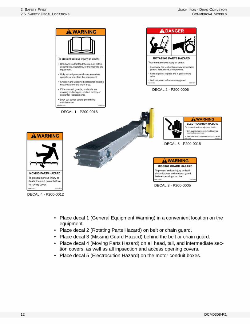
• Place decal 1 (General Equipment Warning) in a convenient location on the equipment.
• Place decal 2 (Rotating Parts Hazard) on belt or chain guard.• Place decal 3 (Missing Guard Hazard) behind the belt or chain guard.• Place decal 4 (Moving Parts Hazard) on all head, tail, and intermediate sec-
tion covers, as well as all inpsection and access opening covers.• Place decal 5 (Electrocution Hazard) on the motor conduit boxes.
DECAL 2 - P200-0006
DECAL 4 - P200-0012
DECAL 1 - P200-0016
DECAL 3 - P200-0005
DECAL 5 - P200-0018
12 DCM0308-R1

UNION IRON - DRAG CONVEYOR 3. INSTALLATION
COMMERCIAL MODELS 3.1. SHIPPING CHECK
3. Installation
3.1. SHIPPING CHECK
Immediately check that all items in the shipment have been received and are undamaged (check for bent or dented casing sections, and look over the covers, buckets, chain guards, drives, etc.).
Note: Mark claims for damaged parts on the shipping papers and immediately file a claim. Do not attempt to install a damaged item.
3.2. LIFTING AND MOVING
Take extreme care to prevent damage when moving assembled conveyors or components. Spreader bars with slings are the recommended support method for lifting. The unsupported span should be no longer than 10’ to 12’.
Never lift a conveyor with only one support point. When choosing supports points for especially heavy items such as drives or gates, consider the weight of an item in relation to load balance and its bending effect.
3.3. ASSEMBLY
Figure 3.1
Warning: Before continuing, please read the safety information relevant to this section in the safety section of this manual. Failure to follow the safety instructions can result in serious injury, death, or property damage.
NOTICE
Lifting the conveyor without proper support could damage the conveyor or components.
DCM0308-R1 13

3. INSTALLATION UNION IRON - DRAG CONVEYOR
3.4. INSTALLATION COMMERCIAL MODELS
Figure 3.1 is a representative drawing only. It is the responsibility of the purchaser to consult contract drawings for specific items on each conveyor.
For safety and proper operation, drag conveyors must be assembled and erected straight and true. The purchaser is responsible for ensuring all support and mounting surfaces are straight and level so there is no distortion in the conveyor.
All component pieces (or conveyor sections) should be placed in proper sequence before assembly is started.
3.4. INSTALLATION
For shop-assembled conveyors, units are match marked and shipped in the longest sections practical for shipment.
Field assembly can be accomplished by connecting marked joints in accordance with the packing list and/or drawing if applicable. In field erection, the mounting surfaces for supporting the conveyor must be level and true so there is no distortion in the conveyor. Shims or grout should be used when required. Frequently check for straightness during assembly.
Drag conveyors should be supported every 10’. Support leg brackets are furnished for conveyor support legs. Conveyor support legs are the responsi-bility of the installer/owner.
For conveyor assemblies purchased as parts or merchandise, assemble according to the following procedure:
1. Place conveyor troughs in proper sequence with tail, bypass inlet, and head in proper location.
2. Connect the trough flanges loosely. Do not tighten bolts.3. Align the trough bottom centerlines perfectly using piano wire (or equivalent);
then tighten flange bolts.4. Tighten all anchor bolts.
Note: In Figure 3.2, "A" dimension should be equal for full length of trough; bottom must be smooth through joints.
Figure 3.2
5. Before connecting the top section of chain, loosen take-up as much as possible. Check sprocket alignment. Check set screws and bearing bolts for tightness.
6. Connect top section for the chain. (On long conveyors, a come-a-long may be necessary.)
14 DCM0308-R1

UNION IRON - DRAG CONVEYOR 3. INSTALLATION
COMMERCIAL MODELS 3.5. INSTALLATION FOR TORQUE-ARM II SPEED REDUCER
7. Adjust take-up to remove excess slack from chain making sure that adjustment screws have been tightened equally to prevent misalignment.
8. Install trough covers in the proper sequence. Handle covers with reasonable care to avoid warping or bending. Covers should be securely fastened.
9. Install drive at the proper location and in accordance with separate instructions provided.
10. Rotate conveyor by hand to ensure that no binding occurs.Note: Re-check assembly steps if binding does occur
11. Check for proper direction of chain and flight travel after electrical connections have been made and before attempting to handle material.
12. If necessary, after lock out / tag out, reconnect electrical leads to reverse direction of material flow. Material should be pushed by the flight and attachment.
Note: All electrical work must be performed by a licensed electrician.
13. Attach all gates, feed chute, discharge chute, etc., and connect all safety devices and controls according to the assembly drawing for your conveyor, included as an insert in this manual. Carefully test to ensure proper operation.
3.5. INSTALLATION FOR TORQUE-ARM II SPEED REDUCER
1. Use lifting bracket to lift reducer.2. Install the magnetic drain plug in the hole
closest to the bottom of the reducer. Throw away the tape that covers the filter/ventilation plug in shipment and install plug in topmost hole. Of the 2 remaining plugs on the sides of the reducer, the lowest one is the minimum oil level plug.
3. Mount reducer on driven shaft as follows: For Taper Bushed Reducer: Mount reducer on driven shaft per instruction in Torque-Arm II Bushing Installation section of this manual.
4. Install sheave on input shaft as close to reducer as practical. (See Figure 3.4)5. If not using a Dodge Torque-Arm II motor mount, install motor and V-belt
drive so belt will approximately be at right angles to the centerline between driven and input shaft. (See Figure 3.5) This will permit tightening the V-belt with the torque arm.
6. Install torque arm and adapter plates reusing the reducer bolts. The adapter plates will fit in any position around the input end reducer.
Table 3.1 Vent and Plug Locations
1 2 3 4 5 6Drain Vent Level Plug Plug Plug
Figure 3.3 Mounting Position
DCM0308-R1 15

3. INSTALLATION UNION IRON - DRAG CONVEYOR
3.5. INSTALLATION FOR TORQUE-ARM II SPEED REDUCER COMMERCIAL MODELS
7. Install torque arm on reducer and equipment using hardware provided. (See Figure 3.5 & 3.6) Make sure that there is sufficient take-up in the turnbuckle for belt tension adjustment when using V-belt drive.
8. Fill gear reducer with recommended lubricant. See Table 3.2.
Figure 3.4 Reducer and Sheave Installation
Figure 3.5 Angle of V-Drive
Figure 3.6 Angle of Torque-Arm
CAUTION
Unit is shipped without oil. Add proper amount of recommended lubricant before operating. Failure to observe this precautions could result in damage or destruction of the equipment.
16 DCM0308-R1
UNION IRON - DRAG CONVEYOR 3. INSTALLATION
COMMERCIAL MODELS 3.5. INSTALLATION FOR TORQUE-ARM II SPEED REDUCER
3.5.1. TORQUE-ARM II BUSHING INSTALLATION
STANDARD TAPER BUSHINGS:
1. One bushing assembly is required to mount the reducer on the driven shaft. An assembly consists of two tapered bushings, bushing screws and washers, two bushing backup plates and retaining rings, and necessary shaft key or keys. The driven shaft must extend through the full length of the reducer.
2. Install one bushing backup plate on the end of the hub and secure with the supplied retaining ring. Repeat procedure for other side.
3. Place one bushing, flange end first, onto the driven shaft and position per dimension “A”, as shown in Table 1. This will allow the bolts to be threaded into the bushing for future bushing and reducer removal.
4. Insert the output key in the shaft and bushing. For ease of installation, rotate the driven shaft so that the shaft keyseat is at the top position.
5. Mount the reducer on the driven shaft and align the shaft key with the reducer hub keyway. Maintain the recommended minimum distance “A” from the shaft bearing.
6. Insert the screws, with washers installed, in the unthreaded holes in the bushing flange and align with the threaded holes in the bushing backup plate. If necessary, rotate the bushing backup plate to align with the bushing screws. Tighten the screws lightly.
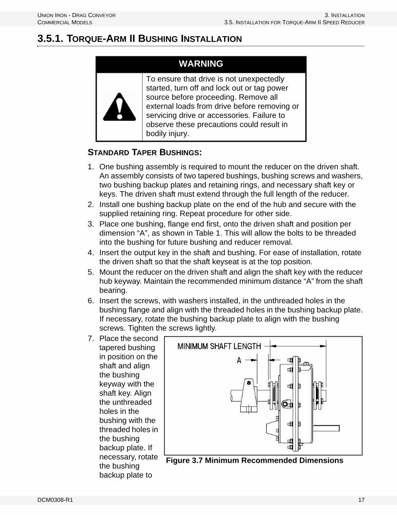
7. Place the second tapered bushing in position on the shaft and align the bushing keyway with the shaft key. Align the unthreaded holes in the bushing with the threaded holes in the bushing backup plate. If necessary, rotate the bushing backup plate to
WARNING
To ensure that drive is not unexpectedly started, turn off and lock out or tag power source before proceeding. Remove all external loads from drive before removing or servicing drive or accessories. Failure to observe these precautions could result in bodily injury.
Figure 3.7 Minimum Recommended Dimensions
DCM0308-R1 17
3. INSTALLATION UNION IRON - DRAG CONVEYOR
3.5. INSTALLATION FOR TORQUE-ARM II SPEED REDUCER COMMERCIAL MODELS
align with the bushing holes. Insert bushing screws, with washers installed in the unthreaded holes in the bushing. Tighten screws lightly.
8. Alternately and evenly tighten the screws in the bushing nearest the equipment to the recommended torque given in Table 3.2. Repeat procedure on outer bushing.
SHORT SHAFT BUSHING
1. The long bushing is designed to be installed from the side of the reducer opposite the driven equipment as shown in Figure 3.7. The long bushing when properly installed is designed to capture the end of the shaft that does not extend through the reducer. Normally the reducer would be mounted such that the input shaft extends from the side of the reducer opposite the driven equipment however the reducer design allows installation of the reducer to be mounted in the opposite direction.
2. Install the tapered bushing wedge into the hollow bore of the reducer from the same side as the long bushing will be installed. When installing the tapered bushing wedge into the reducer hub, install the flange end first so that the thin taper is pointing outwards towards the long bushing as shown in Figure 3.7. The wedge is properly installed when it snaps into place in the reducer hub.
3. Align the tapered bushing wedge keyway with the reducer hub keyway. The keyway in the wedge is slightly wider than the keyway in the reducer hub allowing for easier installation.
4. Install one bushing backup plate on the end of the hub and secure with the supplied retaining ring. Repeat procedure for other side.
5. Install the short bushing; flange first, on the driven shaft and position per dimension “A”, as shown in Table 3.2. This will allow the bolts to be threaded into the bushing for future bushing and reducer removal.
6. Insert the output key in the shaft and bushing. For easy of installation, rotate the driven shaft so that the shaft keyseat is at the top position.
7. Mount the reducer on the driven shaft and align the shaft key with the reducer hub keyway. Maintain the recommended minimum distance “A” from the shaft bearing.
8. Insert the screws, with washers installed, in the unthreaded holes in the bushing flange and align with the threaded holes in the bushing backup plate. If necessary, rotate the bushing backup plate to align with the bushing screws. Tighten the screws lightly.
Table 3.2 Bushing Screw Information and Minimum Clearance for Removal
Reducer Size Fastener Size Torque in Ft. Lbs. ATA0107L 5/16-18 20-17 1.08TA1107H 5/16-18 20-17 1.20TA2115H 3/8-16 20-17 1.20TA3203H 3/8-16 20-17 1.20TA4207H 3/8-16 26-23 1.48TA5215H 1/2-13 77-67 1.81TA6307H 1/2-13 77-67 1.81TA7315H 1/2-13 77-67 2.06
18 DCM0308-R1

UNION IRON - DRAG CONVEYOR 3. INSTALLATION
COMMERCIAL MODELS 3.5. INSTALLATION FOR TORQUE-ARM II SPEED REDUCER
9. Place the long bushing in position on the shaft and align the bushing keyway with the shaft key. Use care to locate the long bushing with the tapered bushing wedge installed earlier. Align the unthreaded holes in the bushing with the threaded holes in the bushing backup plate. If necessary, rotate the bushing backup plate to align with the bushing holes. Insert bushing screws, with washers installed in the unthreaded holes in the bushing. Tighten screws lightly.
10. Alternately and evening tighten the screws in the bushing nearest the equipment to the recommended torque given in Table 3.2. Repeat procedure on outer bushing.
DCM0308-R1 19

3. INSTALLATION UNION IRON - DRAG CONVEYOR
3.5. INSTALLATION FOR TORQUE-ARM II SPEED REDUCER COMMERCIAL MODELS
20 DCM0308-R1
UNION IRON - DRAG CONVEYOR 4. OPERATION
COMMERCIAL MODELS 4.1. PRE-OPERATION
4. Operation
Important: Do not operate Drag Conveyors unless the housing completely encloses the moving elements and power transmission guards are in place.
4.1. PRE-OPERATION
Before operating the Drag Conveyor check to ensure:
1. Lubricate all bearings and drives.2. Interior: Check the interior of the Drag Conveyor to ensure all tools, foreign
materials, and other obstructions have been removed. 3. Hardware: Check that all hardware is secure.4. Set screws: Check all set screws on pulleys, bearings, sprockets, sheaves,
gear reducers, etc. Although some set screws may have been installed at the factory, shipment, handling, and installation could have loosened them. We cannot be responsible for damage caused by loose set screws.
5. Level: Check that the head shaft is level.6. Drive: Check for proper rotation of motor and gear reducer and ensure
electric motor conduit housing cover is in place. If not in place, lockout power before replacing.
7. Tail: Adjust take-up screws so that there is no slack in the chain and so that the tail shaft is level.
8. Lubrication: Lubricate all bearings and drives according to service instructions. Bearings and gear reducers are normally shipped without lubricant. Refer to bearing and gear reducer manufacturer’s service instructions for recommended lubricant.
9. Guards: Install all covers, guards, safety devices or controls, and any interlock to other equipment and ensure they are operating properly.
4.2. START-UP
Operate the empty conveyor for several hours as a break-in period. Look for bearing heat, unusual noises, or drive misalignment. Should any of these occur, check the following and take corrective steps.
Warning: Before continuing, please read the safety information relevant to this section in the safety section of this manual. Failure to follow the safety instructions can result in serious injury, death, or property damage.
DCM0308-R1 21
4. OPERATION UNION IRON - DRAG CONVEYOR
4.3. GENERAL COMMERCIAL MODELS
1. When anti-friction bearings are used, check for proper lubrication. Insufficient or excessive lubricant will cause high operating temperatures.
2. Check assembly and mounting bolts and set screws; tighten if necessary.
After running the conveyor, stop it, lock out all power, and check discharge to ensure it is clear and material flow through the discharge will not be impeded in any way.
3. Restart the conveyor and gradually feed material. Gradually increase feed rate until the design capacity is reached.
Important: Do not overload conveyor. Do not exceed conveyor speed, capacity, material density, or rate of flow for which the conveyor and drive were designed.
4. Cut off feed and allow the conveyor to empty. Lock out power supply. Check all bolts and all alignments. Realign as necessary, tighten all bolts, and check chain adjustment.
5. Check motor amperage frequently. 6. Check chain tension periodically. It may be necessary to readjust chain
tension after running material in the conveyor.7. If the conveyor will not be operated for a prolonged period of time (one month
or longer), operate until cleared of all material. This is particularly important when the material conveyed tends to harden, become more viscous or sticky, or spoils if allowed to stand for a period of time.
4.3. GENERAL
• Run the conveyor empty for a few minutes periodically to check for excessive vibration, loose fasteners, security of covers and guards, noise, and bearing and drive temperature.
• Always operate the conveyor with covers, guards, and safety labels in place.• Always practice good housekeeping and keep a clear view of the conveyor
loading, discharges, and all safety devices.
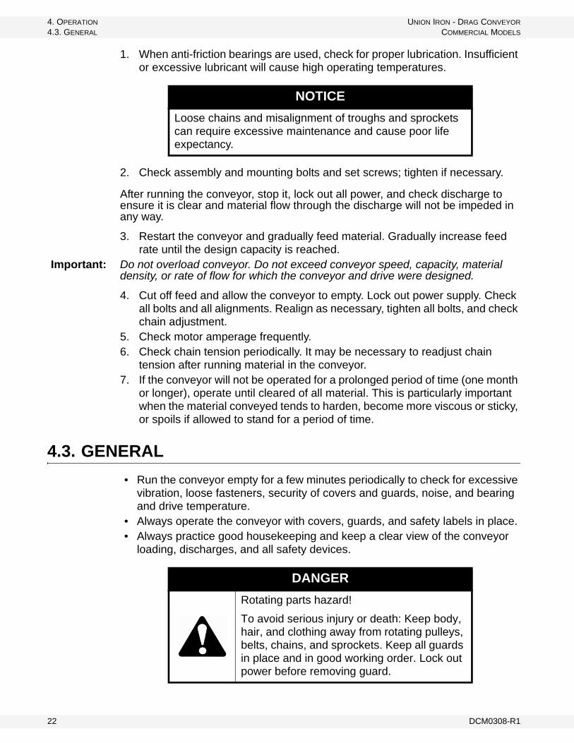
NOTICE
Loose chains and misalignment of troughs and sprockets can require excessive maintenance and cause poor life expectancy.
DANGER
Rotating parts hazard!
To avoid serious injury or death: Keep body, hair, and clothing away from rotating pulleys, belts, chains, and sprockets. Keep all guards in place and in good working order. Lock out power before removing guard.
22 DCM0308-R1
UNION IRON - DRAG CONVEYOR 5. MAINTENANCE
COMMERCIAL MODELS
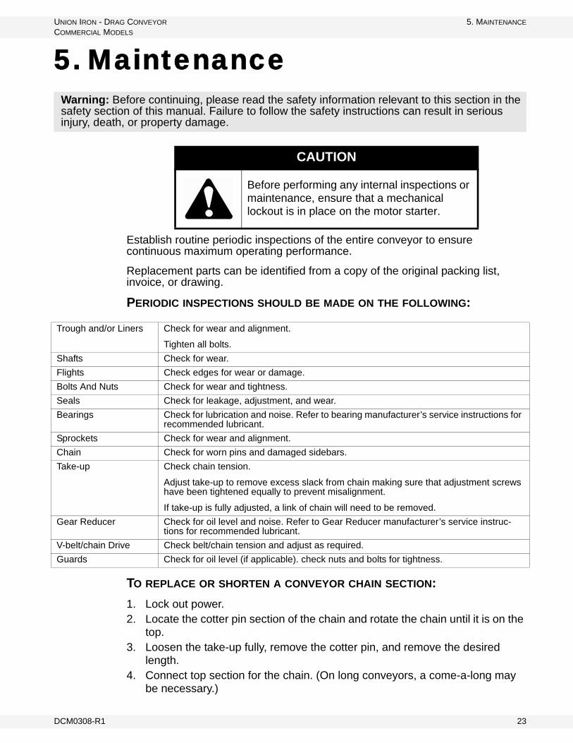
5. Maintenance
Establish routine periodic inspections of the entire conveyor to ensure continuous maximum operating performance.
Replacement parts can be identified from a copy of the original packing list, invoice, or drawing.
PERIODIC INSPECTIONS SHOULD BE MADE ON THE FOLLOWING:
TO REPLACE OR SHORTEN A CONVEYOR CHAIN SECTION:
1. Lock out power.2. Locate the cotter pin section of the chain and rotate the chain until it is on the
top.3. Loosen the take-up fully, remove the cotter pin, and remove the desired
length.4. Connect top section for the chain. (On long conveyors, a come-a-long may
be necessary.)
Warning: Before continuing, please read the safety information relevant to this section in the safety section of this manual. Failure to follow the safety instructions can result in serious injury, death, or property damage.
CAUTION
Before performing any internal inspections or maintenance, ensure that a mechanical lockout is in place on the motor starter.
Trough and/or Liners Check for wear and alignment.
Tighten all bolts.
Shafts Check for wear.
Flights Check edges for wear or damage.
Bolts And Nuts Check for wear and tightness.
Seals Check for leakage, adjustment, and wear.
Bearings Check for lubrication and noise. Refer to bearing manufacturer’s service instructions for recommended lubricant.
Sprockets Check for wear and alignment.
Chain Check for worn pins and damaged sidebars.
Take-up Check chain tension.
Adjust take-up to remove excess slack from chain making sure that adjustment screws have been tightened equally to prevent misalignment.
If take-up is fully adjusted, a link of chain will need to be removed.
Gear Reducer Check for oil level and noise. Refer to Gear Reducer manufacturer’s service instruc-tions for recommended lubricant.
V-belt/chain Drive Check belt/chain tension and adjust as required.
Guards Check for oil level (if applicable). check nuts and bolts for tightness.
DCM0308-R1 23

5. MAINTENANCE UNION IRON - DRAG CONVEYOR
5.1. PROJECTED CHAIN CONVEYOR MAINTENANCE COMMERCIAL MODELS
5. To reassemble, follow the above steps in reverse order.
5.1. PROJECTED CHAIN CONVEYOR MAINTENANCE
Every six months, perform routine maintenance for bearing, sprocket, and chain life, including lubrication of bearings, inspection of sprockets and shain for wear, and proper chain tensioning.
Three years after installation, replace wear items such as UHMW Flights, AR Plate Liners, and Return Rail Caps. Refer to Table 5.1 for expected liner life.
Five years after installation, replace chain and sprockets if necessary. (If Chain measures 5% elongation, it should be replaced.)
Note: The above information is affected by material being conveyed, surrounding conditions, and quality of preventative maintenance.
5.2. TORQUE-ARM II SPEED REDUCER MAITENANCE
5.2.1. BUSHING REMOVAL FOR STANDARD TAPER BUSHINGS
1. Remove bushing screws.2. Place the screws in the threaded holes provided in the bushing flanges.
Tighten the screws alternately and evenly until the bushings are free on the shaft. For ease of tightening screws make sure screw threads and threaded holes in the bushing flanges are clean.
3. Locate two (2) wedges at 180° between the bushing flange and the bushing backup plate. Drive the wedges alternately and evenly until the bushing is free on the shaft.
4. Remove the outside bushing, the reducer, and then the inboard bushing.
Table 5.1
CHAIN SPEED(FPM)
HOURSa EXPECTED LIFE1/4" THICKNESS 3/8" THICKNESS 1/2" THICKNESS
M.S.b A.R.c M.S. A.R. M.S. A.R.
100 7,500 15,000 12,500 25,000 17,500 35,000150 5,000 10,000 8,000 16,500 11,500 23.000200 3,750 7,500 6,250 12,500 8,500 17,500250 3,000 6.000 5,000 10,000 7,000 14,000300 2,500 5,000 4,000 8,200 5,500 11,500
a. Hours in the above chart are based on clean corn. For clean soybeans, use 50% of the hours shown above. For dirty soybeans, use 50% of the hours for clean soybeans.
b. M. S. - denotes mild steel plate; c. A. R. - denotes abrasion resistant steel plate.
24 DCM0308-R1
UNION IRON - DRAG CONVEYOR 5. MAINTENANCE
COMMERCIAL MODELS 5.2. TORQUE-ARM II SPEED REDUCER MAITENANCE
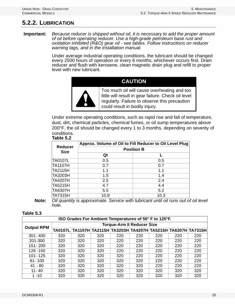
5.2.2. LUBRICATION
Important: Because reducer is shipped without oil, it is necessary to add the proper amount of oil before operating reducer. Use a high-grade petroleum base rust and oxidation inhibited (R&O) gear oil - see tables. Follow instructions on reducer warning tags, and in the installation manual.
Under average industrial operating conditions, the lubricant should be changed every 2500 hours of operation or every 6 months, whichever occurs first. Drain reducer and flush with kerosene, clean magnetic drain plug and refill to proper level with new lubricant.
Under extreme operating conditions, such as rapid rise and fall of temperature, dust, dirt, chemical particles, chemical fumes, or oil sump temperatures above 200°F, the oil should be changed every 1 to 3 months, depending on severity of conditions.
Note: Oil quantity is approximate. Service with lubricant until oil runs out of oil level hole.
CAUTION
Too much oil will cause overheating and too little will result in gear failure. Check oil level regularly. Failure to observe this precaution could result in bodily injury.
Table 5.2
Reducer Size
Approx. Volume of Oil to Fill Reducer to Oil Level PlugPosition B
Qt LTA0107L 0.5 0.5TA1107H 0.7 0.7TA2115H 1.1 1.1TA3203H 1.5 1.4TA4207H 2.5 2.4TA5215H 4.7 4.4TA6307H 5.5 5.2TA7315H 10.8 10.3
Table 5.3 ISO Grades For Ambient Temperatures of 50° F to 125°F.
Output RPMTorque-Arm II Reducer Size
TA0107L TA1107H TA2115H TA3203H TA4207H TA5215H TA6307H TA7315H301- 400 320 320 320 220 220 220 220 220201-300 320 320 320 220 220 220 220 220151- 200 320 320 320 220 220 220 220 220126 -150 320 320 320 220 220 220 220 220101- 125 320 320 320 320 220 220 220 22081- 100 320 320 320 320 320 220 220 22041 - 80 320 320 320 320 320 220 220 22011- 40 320 320 320 320 320 320 320 3201 -10 320 320 320 320 320 320 320 320
DCM0308-R1 25
5. MAINTENANCE UNION IRON - DRAG CONVEYOR
5.3. DRAG CONVEYOR EXTENDED SHUTDOWN/STORAGE COMMERCIAL MODELS
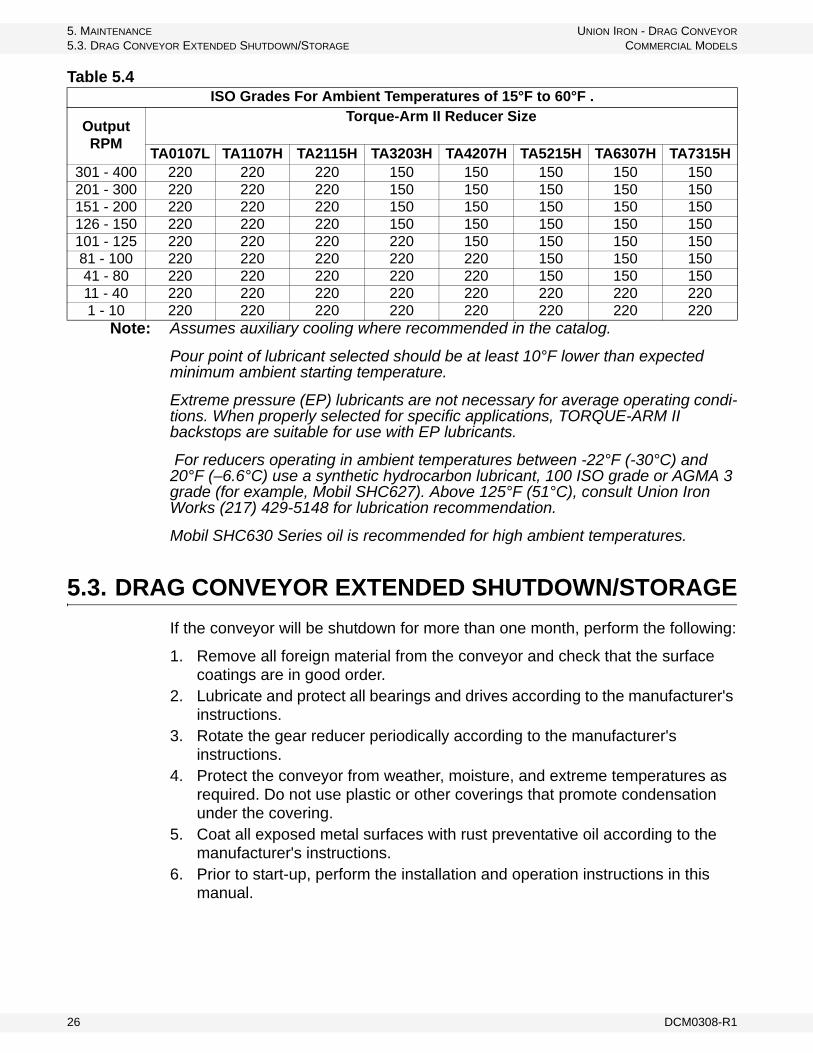
Note: Assumes auxiliary cooling where recommended in the catalog.
Pour point of lubricant selected should be at least 10°F lower than expected minimum ambient starting temperature.
Extreme pressure (EP) lubricants are not necessary for average operating condi-tions. When properly selected for specific applications, TORQUE-ARM II backstops are suitable for use with EP lubricants.
For reducers operating in ambient temperatures between -22°F (-30°C) and 20°F (–6.6°C) use a synthetic hydrocarbon lubricant, 100 ISO grade or AGMA 3 grade (for example, Mobil SHC627). Above 125°F (51°C), consult Union Iron Works (217) 429-5148 for lubrication recommendation.
Mobil SHC630 Series oil is recommended for high ambient temperatures.
5.3. DRAG CONVEYOR EXTENDED SHUTDOWN/STORAGE
If the conveyor will be shutdown for more than one month, perform the following:
1. Remove all foreign material from the conveyor and check that the surface coatings are in good order.
2. Lubricate and protect all bearings and drives according to the manufacturer's instructions.
3. Rotate the gear reducer periodically according to the manufacturer's instructions.
4. Protect the conveyor from weather, moisture, and extreme temperatures as required. Do not use plastic or other coverings that promote condensation under the covering.
5. Coat all exposed metal surfaces with rust preventative oil according to the manufacturer's instructions.
6. Prior to start-up, perform the installation and operation instructions in this manual.
Table 5.4 ISO Grades For Ambient Temperatures of 15°F to 60°F .
Output RPM
Torque-Arm II Reducer Size
TA0107L TA1107H TA2115H TA3203H TA4207H TA5215H TA6307H TA7315H301 - 400 220 220 220 150 150 150 150 150201 - 300 220 220 220 150 150 150 150 150151 - 200 220 220 220 150 150 150 150 150126 - 150 220 220 220 150 150 150 150 150101 - 125 220 220 220 220 150 150 150 15081 - 100 220 220 220 220 220 150 150 15041 - 80 220 220 220 220 220 150 150 15011 - 40 220 220 220 220 220 220 220 2201 - 10 220 220 220 220 220 220 220 220
26 DCM0308-R1

UNION IRON - DRAG CONVEYOR 5. MAINTENANCE
COMMERCIAL MODELS 5.4. TORQUE-ARM II SPEED REDUCER STORAGE
5.4. TORQUE-ARM II SPEED REDUCER STORAGE
During periods of long storage, or when waiting for delivery or installation of other equipment, special care should be taken to protect a gear reducer to have it ready to be in the best condition when placed into service.
By taking special precautions, problems such as seal leakage and reducer failure due to lack of lubrication, improper lubrication quantity, or contamination can be avoided. The following precautions will protect gear reducers during periods of extended storage:
PREPARATION:
1. Drain oil from the unit. Add a vapor phase corrosion inhibiting oil (VCI-105 oil by Daubert Chemical Co.) in accordance with Table 5.5.
2. Seal the unit airtight. Replace the vent plug with a standard pipe plug and wire the vent to the unit.
3. Cover all unpainted exterior parts with a waxy rust preventative compound that will keep oxygen away from the bare metal. (Non-Rust X-110 by Daubert Chemical Co. or equivalent)
4. The instruction manuals and lubrication tags are paper and must be kept dry. Either remove these documents and store them inside, or cover the unit with a durable waterproof cover which can keep moisture away.
5. Protect reducer from dust, moisture, and other contaminants by storing the unit in a dry area.
6. In damp environments, the reducer should be packed inside a moisture-proof container or an envelope of polyethylene containing a desiccant material. If the reducer is to be stored outdoors, cover the entire exterior with a rust preventative.
When placing the reducer into service:
1. Fill the unit to the proper oil level using a recommended lubricant. The VCI oil will not affect the new lubricant.
2. Clean the shaft extensions with petroleum solvents.3. Assemble the vent plug into the proper hole.
Follow the installation instructions provided in this manual.
VCI #105 and #10 are interchangeable.
VCI #105 is more readily available.
Table 5.5 Quantities of VCI #105 OilReducer Size Quantity (Ounces / Millilitre)
TA0107L 1 / 30TA1107H 1 / 30TA2115H 1 / 30TA3203H 1 / 30TA4207H 1 / 30TA5215H 2 / 59TA6307H 2 / 59TA7315H 3 / 89
DCM0308-R1 27
5. MAINTENANCE UNION IRON - DRAG CONVEYOR
5.4. TORQUE-ARM II SPEED REDUCER STORAGE COMMERCIAL MODELS
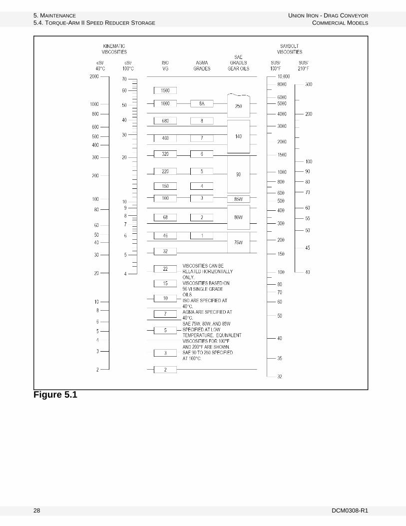
Figure 5.1
28 DCM0308-R1

UNION IRON - DRAG CONVEYOR 6. TROUBLESHOOTING
COMMERCIAL MODELS
6. TroubleshootingPROBLEM CAUSE REMEDY
Premature trough failure and/or liner
Gauge too light Increase thickness. Consult Union Iron Works for recommendations
Worn flights Replace flights
Excessive chain speed Check chain speed
Accelerated flight wear
Excessive heat Change flight material. UHMW is limited to 175°F
Speed too high Reduce speed. Consult Union Iron Works to determine proper chain speed
Foreign objects Remove foreign objects
Chain breakage
Worn chain Replace chain if worn
Take-up is loose Adjust take-up (See Maintenance Section)
Obstruction in conveyor Remove obstruction
Sprocket misalignment Align sprockets
Plugged discharge Remove plug
Overloading conveyor Regulate feed into conveyor
Drive shaft breakage
Excessive torque Recalculate horsepower require-ments
Insufficient torque capacity.
Increase diameter of shaft
Change shaft material
Obstruction in conveyor Remove obstruction
Overloading conveyor Regulate feed into conveyor
Bearing Failure
Material getting into bearing
Add or upgrade seal to keep material out of bearing
Change to outboard bearing
Insufficient/excessive lubrication
Lubricate properly (See Mainte-nance Section.)
Motor/heaters overload
Amp demand excessive for motor
Recheck horsepower calculations
Check material characteristics
Check capacity
Regulate feed
Drastic capacity loss Missing flights Replace flights
DCM0308-R1 29

6. TROUBLESHOOTING UNION IRON - DRAG CONVEYOR
COMMERCIAL MODELS
30 DCM0308-R1

LIMITED WARRANTYSeller warrants that all of the goods sold hereunder will conform to their description in Seller's published literature current at the time the Buyer's order is accepted, that Seller will use good material and workmanship in the manufacture of such goods, and that such goods will conform to applicable laws and regulations regarding purity.
Seller will repair or replace, at its discretion, any nonconforming goods (or refund their purchase price at Seller's option), but only if Seller receives written notice of nonconformity within 60 days after shipment and Buyer's remedies hereunder are expressly so limited.
Seller makes no other warranties of any kind with respect to such goods or any part thereof, express or implied. All implied warranties of merchantability and fitness for a particular purpose are hereby disclaimed by seller and excluded from this agreement, and such goods are sold “as is” and with all faults.
Seller will have no liability for consequential damages of any kind, including damages arising from bodily injury or the loss of use of such goods or other property. Buyer releases all claims for such damages, whether based on contract, warranties, strict liability, or negligence.

601 S. 27th Street
P.O. Box 1038
Decatur, IL 62525 USA
Phone: (217) 429-5148
Fax: (217) 429-5149
Website: www.unionironworks.com