
Draft National Broadband Network Reference Architecture Oct 2009
26
Draft - Version 1.9 14 Oc to b er 2009 For Disc ussion On ly COMMUNICATIONS ALLIANCE LTD NATIONAL BROADBAND NETWORK R E F E R E NC E A R C HI T E C T UR E HIG H LE V E L A R C HIT E C T UR E O PT IO NS F O R T HE NBN DRAFT FOR COMMENT OCTOBER 2009
-
Upload
kishor-kumar -
Category
Documents
-
view
216 -
download
0
Transcript of Draft National Broadband Network Reference Architecture Oct 2009
8/8/2019 Draft National Broadband Network Reference Architecture Oct 2009
http://slidepdf.com/reader/full/draft-national-broadband-network-reference-architecture-oct-2009 1/26
Draft - Version 1.9 14 Oc tober 2009 For Discussion Only
COMMUNICATIONS
ALLIANCE LTD
NATIONAL BROADBAND NETWORK
REFERENCE ARCHITECTURE
HIGH LEVEL ARCHITECTURE OPTIONS FOR THE NBN
DRAFT FOR COMMENT
OCTOBER 2009
8/8/2019 Draft National Broadband Network Reference Architecture Oct 2009
http://slidepdf.com/reader/full/draft-national-broadband-network-reference-architecture-oct-2009 2/26
DRAFT National Broa db and Network Referenc e Arc hitec tureHigh Leve l Architec ture Op tions for the NBN pa per
Com munic ations Alliance Ltd (formerly Australian
Communications Industry Forum Ltd) was formed in 2006
to provide a unified voice for the Australian
comm unications industry a nd to lead it into the next
generation of c onverging networks, technologies and
services.
Disclaimers
1) Notwithstand ing anything co ntained in this draft p ap er:
a) Co mm unica tions Alliance d isc laims respo nsibility (inc luding
whe re Com munica tions Alliance or a ny of its officers,
emp loyees, age nts or co ntrac tors has be en neg lige nt) for any
direct or indirect loss, damage, claim, or liability any person
may incur as a result of any:
i) reliance on or compliance with this draft paper;
ii) inacc uracy o r inap prop riate ness of this draft p ap er; or
iii) inconsistenc y of this draft pa pe r with any law ; and
b) Co mm unica tions Alliance d isc laims respo nsibility (inc luding
whe re Com munica tions Alliance or a ny of its officers,
emp loyees, age nts or co ntrac tors has be en neg ligen t) for
ensuring c om pliance by a ny person w ith this draft p ap er.
2) The a bo ve d isclaimers will not a pp ly to the e xtent they a re
inco nsisten t with a ny relevan t legislation.
Copyright
© Communications Alliance Ltd 2009
This do cum ent is co pyright a nd must not b e used excep t a s pe rmitted
below o r under the Cop yright Ac t 1968 . You may reproduc e and p ublish
this do cum ent in who le or in part for your or your organisation’ s own
personal or internal compliance, educational or non-commercial
purpo ses. You must not alter or amend this do cum ent in any way. You
must not reprod uce or pub lish this do c ument fo r com merc ial gain
without the prior written c onsent o f Com munica tions Alliance .
Organisations wishing to reproduc e or p ublish this do c ument for
commercial gain (i.e. for distribution to subscribers to an information
service ) ma y ap ply to subsc ribe to the Com munica tions Alliance
Publications Subscription Service by co ntac ting the Com munica tions
Alliance Co mm ercial Ma nag er at info@co mm salliance .com .au. If you
publish any part of this document for any purpose, you must also publish
this co pyright no tice a s pa rt of tha t pub lica tion.
DRAFT NBN REFERENCE ARCHITECTURE OCTOBER 2009
HIGH LEVEL ARCHITECTURE OPTIONS FOR THE NBN COPYRIGHT
8/8/2019 Draft National Broadband Network Reference Architecture Oct 2009
http://slidepdf.com/reader/full/draft-national-broadband-network-reference-architecture-oct-2009 3/26
- 1 -
TABLE OF CONTENTS
1 PURPOSE AND SCOPE 2 2 BROADBAND NETWORK ARCHITECTURE VISION 3 3 BROADBAND NETWORK REFERENCE ARCHITECTURE – FTTP ACCESS 4
3.1 Key Network Doma ins and Func tions 4 3.2 Wholesale Point of Interconnec t and Service Boundary Point Scena rios
8 3.3 Roles and Rela tionships between Different Industry Players 10 3.4 Rela tionship be tween CPE and Reta il/Wholesale providers 12
4 BROADBAND NETWORK REFERENCE ARCHITECTURE – WIRELESS/ SATELLITE
ACCESS 14 4.1 Option 1: Laye r 2 Ethernet Ac cess 14 4.2 Option 2: Wireless/ Satellite Layer 3 IP Ac cess 18
5 FURTHER CONSIDERATIONS 22 5.1 Sustainability 22 5.2 Robustness 22 5.3 Security 22 5.4 IPv6 22 5.5 Future Proo fness 22
6 ABBREVIATIONS 23
Any o utp uts from the Comm unica tions Allianc e NBN Projec t inc luding o n the NBN WIKIand in this do cument do not rep resent preferred Com munica tions Allianc e, industry or
individua l Comm unica tions Allianc e me mb er positions. The outputs in this doc umentrep resent a rang e of scena rios and op tions that the Com munica tions Allianc e wo rking
groups have identified with the purpose of facilitating broader discussion and decision
ma king o n the NBN.
While the scena rios p resented in this pap er are tec hnica lly fea sible, any agreed set o fscena rios will req uire trad eoffs be tween tec hnical a nd op erational comp lexity verses
req uirements for ma ximum flexibility in supp ort o f func tiona l and service req uirements.
These issues will need further a na lyses as part of more deta iled Comm unica tions Alliance
wo rk stream ac tivities.
DRAFT NBN REFERENCE ARCHITECTURE OCTOBER 2009
HIGH LEVEL ARCHITECTURE OPTIONS FOR THE NBN COPYRIGHT
8/8/2019 Draft National Broadband Network Reference Architecture Oct 2009
http://slidepdf.com/reader/full/draft-national-broadband-network-reference-architecture-oct-2009 4/26
- 2 -
1 PURPOSE AND SCOPE
This doc ume nt has been end orsed by the NBN Referenc e Mo del working g roup
charged with developing a set of high level NBN network architec ture o ptions.
These inputs have b een de velop ed to a ssist the Comm unica tions Allianc e inesta blishing an industry ag reed set of NBN refe renc e a rc hitec ture op tions.
This doc ume nt d efines the following:
• The end -to-end broad ba nd ne two rk architecture framew ork, inc luding
do ma ins and funct ions req uired to de liver a wide rang e o f netw ork servic es
and ap plicat ion/ content services to e nd users.
• A range of potential passive and active NBN wholesale interconnect scenarios.
This will be a key input to other Comm unica tions Allianc e NBN work stream
activities, in p articula r the who lesa le services stream . In deve loping these
options there has been some regard to overseas experience where different
FTTH who lesa le op en a cc ess mo dels a re b eing a dop ted by d ifferent c ountries.
• Terminology a nd definitions for different industry players taking into a ccount a
rang e o f possible roles p roviding Wholesa le and Reta il services.
• The rela tionship b etween the CPE (suc h as ONT and RG) a nd Reta il and
Wholesa le Service Providers.
DRAFT NBN REFERENCE ARCHITECTURE OCTOBER 2009
HIGH LEVEL ARCHITECTURE OPTIONS FOR THE NBN COPYRIGHT
8/8/2019 Draft National Broadband Network Reference Architecture Oct 2009
http://slidepdf.com/reader/full/draft-national-broadband-network-reference-architecture-oct-2009 5/26
- 3 -
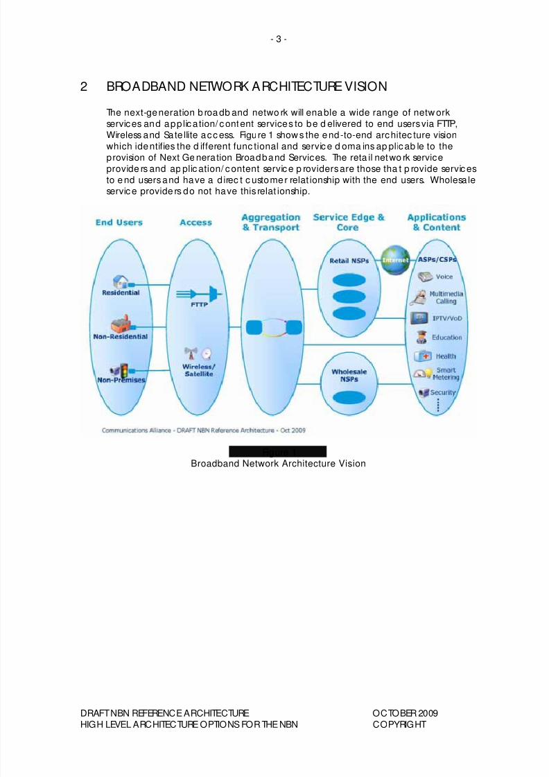
2 BROADBAND NETWORK ARCHITECTURE VISION
The next-generation b roa db and netwo rk will enable a wide range of netw ork
services and app lica tion/ content services to be d elivered to end users via FTTP,
Wireless and Sate llite acc ess. Figure 1 show s the end-to-end architec ture visionwhich identifies the d ifferent func tional and service d oma ins ap plicab le to the
provision of Next Ge neration Broadband Services. The reta il netwo rk service
provide rs and ap plic ation/ content service p roviders are those tha t p rovide services
to e nd users and have a d irec t c ustomer relat ionship with the end users. Wholesa leservice provide rs do not have this relat ionship.
Figure 1Broadband Network Architecture Vision
DRAFT NBN REFERENCE ARCHITECTURE OCTOBER 2009
HIGH LEVEL ARCHITECTURE OPTIONS FOR THE NBN COPYRIGHT
8/8/2019 Draft National Broadband Network Reference Architecture Oct 2009
http://slidepdf.com/reader/full/draft-national-broadband-network-reference-architecture-oct-2009 6/26
- 4 -
3 BROADBAND NETWORK REFERENCE ARCHITECTURE – FTTP
ACCESS
The prima ry form of a ccess to the NBN will be Fibre to the Premises (FTTP). This
sec tion d esc ribes the end -to-end netwo rk a rchitec ture fo r FTTP ac cess.
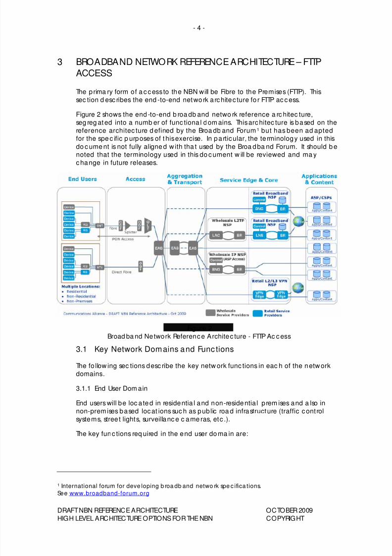
Figure 2 shows the end -to-end b roa db and netwo rk reference a rc hitec ture,
seg reg ated into a numb er of func tiona l dom ains. This architec ture is based on the
reference architec ture d efined by the Broa db and Forum1 but has been ad aptedfor the spe c ific p urposes of this exercise. In particular, the te rminology used in this
do cume nt is not fully aligne d w ith tha t used by the Broa dba nd Forum. It should b enoted that the terminology used in this do cument w ill be reviewed and ma y
change in future releases.
Figure 2
Broad ba nd Network Reference Architec ture - FTTP Ac cess
3.1 Key Network Domains and Func tions
The fo llow ing sec tions desc ribe the key netw ork func tions in eac h of the netw ork
domains.
3.1.1 End User Dom ain
End users will be loc a ted in residentia l and non-residentia l p rem ises and a lso in
non-premises based locat ions suc h as pub lic roa d infrastructure (traffic cont rol
systems, stree t lights, surveillanc e c ame ras, etc .).
The key func tions req uired in the end user do ma in are:
1
International forum for deve loping b roa db and netwo rk spe c ifica tions.See www.broadband-forum.org
DRAFT NBN REFERENCE ARCHITECTURE OCTOBER 2009
HIGH LEVEL ARCHITECTURE OPTIONS FOR THE NBN COPYRIGHT
8/8/2019 Draft National Broadband Network Reference Architecture Oct 2009
http://slidepdf.com/reader/full/draft-national-broadband-network-reference-architecture-oct-2009 7/26
- 5 -
• Optical Network Termina tion (ONT)/ Network Termina tion Unit (NTU) devices
which terminate the op tic al network and provide a range o f end user
interfaces. This device could be loc a ted indoors or outdo ors.
• Routing Gateways (RG) which p rovide a laye r 3 (IP) ga teway func tion between
end d evices and the netwo rk. They inc lude func tions for:IP rout ing, IP ad dress allocat ion to end devices, QoS, Network Add ress
Translat ion (NAT), firewa ll, ma nagem ent, Domain Name Server (DNS) and
network authentication.
A Reta il NSP ma y inc lude a dd itiona l capab ilities on the RG not listed a bove .
• Premises (Hom e) Networks which p rovide c onnec tivity betwee n RGs and end
devices.
• End d evices which can be app licat ion spec ific (e.g. Set Top Boxes, Phone s) or
can be more general in nature (e.g. Personal Computers).
It should be noted that some end de vices do not necessarily need a RG func tion
and can b e c onnec ted direc tly to the ONT.
It should a lso be noted that there a re multiple a rchitec ture op tions to supp ort
multiple service p rovide rs delivering services to the premises and wha t o p tions a re
ap plied will dete rmine the ove rall level of technical comp lexity. This do cument
do es not show a ll of the p ossible a rchitec ture op tions. The w holesa le RG show n in
Figure 2 rep resents only one o f the end user a rc hitec ture op tions.
3.1.2 Ac cess Doma in
The func tion of the Acc ess Doma in is to p rovide conne c tivity from the end user
premises to the ne twork. The Ac cess Domain consists of b oth p assive a nd a c tive
components.
• The p assive com ponents include Op tica l Fibre, Op tica l Sp litte rs, Optica l
Distribution Frames (ODF) and p it and p ipe enc losures.
• The a c tive compone nts include Op tica l Network Termination (ONT) and
Op tica l Line Termina tion (OLT) eq uipm ent .
• Ethernet Aggreg at ion Switc hes (EAS) which agg reg ate multiple OLTs at a loca l
excha nge site.
3.1.3 Aggregation & Transport Domain
The funct ion of the ag grega tion and transpo rt do ma in is to a gg regate a largenumber of a ccess connec tions onto a relatively sma ll number of physical interfac es
and transport these connections from local, distributed locations to centralised
locations such as major regional and metropolitan centres with regional, state or
national scope.
Multiple leve ls of a gg reg ation a re p ossible (e.g. loc a l, reg ional, sta te , nationa l) with
po tential for multiple service p roviders to o pe rate in this dom ain. It should b e
note d tha t service p rovide rs ma y po tent ially provide transpo rt-only services without
any agg rega tion.
The c urrent a nd future trend for providing aggregat ion and transport networks is to
use Ethernet based a gg reg ation and t ransport tec hnolog y. As show n in Figure 2,
Ethernet Ag gregat ion Switc hes (EAS) provide the ag gregat ion func tion.
DRAFT NBN REFERENCE ARCHITECTURE OCTOBER 2009
HIGH LEVEL ARCHITECTURE OPTIONS FOR THE NBN COPYRIGHT
8/8/2019 Draft National Broadband Network Reference Architecture Oct 2009
http://slidepdf.com/reader/full/draft-national-broadband-network-reference-architecture-oct-2009 8/26
- 6 -
3.1.4 Service Edge & Core Domain
The main func tion of this dom ain is to p rovide layer 3 (IP) conne c tivity between endde vices, ap plicat ion/ content services and the public Internet. It can a lso p rovide
layer 2 Ethernet VPN and / or layer 3 IP VPN connec tivity betw een end de vice s,
ap plication/ content services and the public Internet.
In the c ase o f providing broad ba nd IP services, there a re tw o m ain ap proac hes for
de livering end user log ica l co nnec tions into the IP servic e laye r:
The p red ominant ap proac h in use to da y involves ag grega tion of Point-to-po intProtoc ol (PPP) end user c onnec tions into Layer 2 Tunne lling Protocol (L2TP) tunne ls
for delivery into the IP netwo rk service layer. While this app roa ch is adeq uate fo r
providing b est effo rt services, the em ergence o f IP based app lica tions req uiringmore stringe nt Qua lity of Service (QoS) has lead to the deve lopm ent o f an
alternative “Q oS ena bled b roa db and ” a pp roa ch. This alternat ive ap proac hena b les the provision of end-to-end QoS capab ilities a t the IP service laye r by
providing d irec t Ethernet c onnec tivity between the Routing Ga teway (RG) a t theend user premises and the Broa dband Netwo rk Gateway (BNG) within the IP
service layer.
The key func tions of the BNG a re:
• Prov ide the first p oint o f IP routing for end user traffic
• Enforce subsc riber level Qua lity o f Service (QoS) a nd po lic y d ec isions
• Allow IP multica st rep licat ion
The key func tions of the BNG c ont rol plane are:
• Authe ntica tion o f RGs and assoc iation o f RGs with subsc ribed service p rofiles
• IP Address allocation to RGs
• Manag eme nt of QoS po lic ies on the BNG and the RG
It is generally ac cep ted that QoS enabled broad ba nd is likely to be the d ominant
approa ch in the future, however, given the la rge insta lled base o f L2TP based
services, it is likely tha t both a pproa ches will need to b e supported in the p rop osed
NBN timeframe .
Within the Service Edg e and Core d omain, there are a number of d ifferent
wholesale a nd reta il roles tha t c an be de fined :
• Retail Broadband NSP
• Wholesale L2TP Netw ork Service Provider (NSP)
• Wholesale IP NSP
• Retail L2/ L3 VPN NSP
These roles a re further de fined in sec tion 3.3.
DRAFT NBN REFERENCE ARCHITECTURE OCTOBER 2009
HIGH LEVEL ARCHITECTURE OPTIONS FOR THE NBN COPYRIGHT
8/8/2019 Draft National Broadband Network Reference Architecture Oct 2009
http://slidepdf.com/reader/full/draft-national-broadband-network-reference-architecture-oct-2009 9/26
- 7 -
3.1.5 App lication & Content Doma in
This dom ain provides applica tion and content services to end users such as web-ba sed applica tion content , IP Telep hony, IP Video , Sma rt me tering , ed ucation,
health, etc .
Tod ay, the predo minant mea ns of connec tivity betwee n this do ma in and end
users is via the pub lic Internet (also known as “Over The Top ” ). Othe r connec tivity
models a re p ossible to support ap plica tions req uiring d ifferent c apab ilities to t hose
ava ilab le via the Internet. Examp les inc lude sma rt mete ring o f home a pp lianc es,
de livery of high q ua lity video services, etc . The c onne c tivity op tions listed below
are further defined in sec tion 3.3.
• Over The Top (via p ub lic Internet)
• Connec t via Reta il NSPs
• Connec t via a Broa dband Ac cess Provider (Wholesale Layer 2 Ethernet service)
• Co nnec t via a Wholesa le IP NSP.
Eac h of these connec tivity opt ions are d ifferent and will involve a trad eoff in
tec hnic al and op erational comp lexity b etween the e nd user netwo rk, NSPs and
ASPs.
DRAFT NBN REFERENCE ARCHITECTURE OCTOBER 2009
HIGH LEVEL ARCHITECTURE OPTIONS FOR THE NBN COPYRIGHT
8/8/2019 Draft National Broadband Network Reference Architecture Oct 2009
http://slidepdf.com/reader/full/draft-national-broadband-network-reference-architecture-oct-2009 10/26
- 8 -
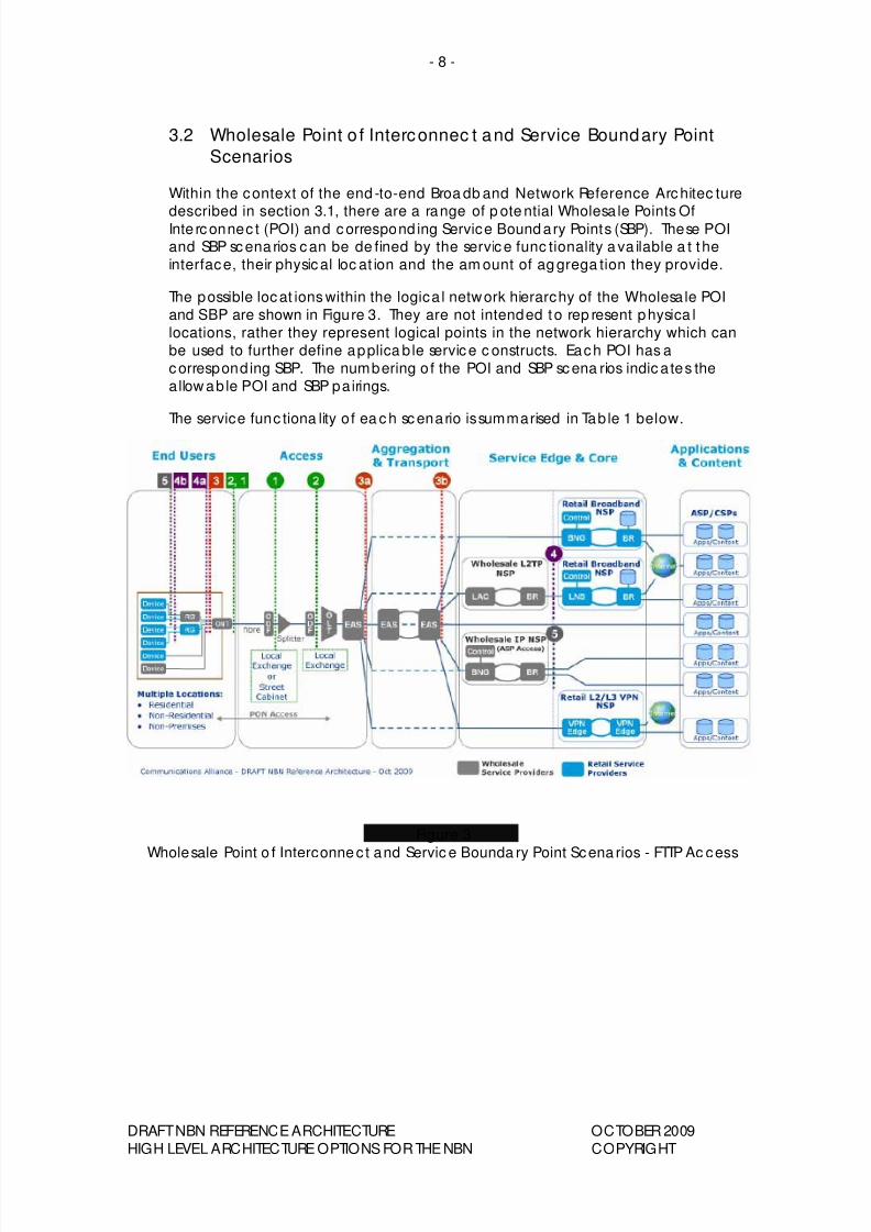
3.2 Wholesale Point o f Interconnec t and Service Boundary Point
Scenarios
Within the context of the end -to-end Broa db and Network Reference Architec ture
described in section 3.1, there are a range of p ote ntial Wholesa le Points OfInte rconnec t (POI) and correspond ing Service Bound ary Points (SBP). These POIand SBP scena rios can be de fined by the service func tionality a va ilable a t the
interface, their physical loc at ion and the am ount of ag grega tion they provide.
The possible locat ions within the logica l network hierarchy of the Wholesa le POI
and SBP are shown in Figure 3. They are not intended to rep resent physica l
locations, rather they represent logical points in the network hierarchy which can
be used to further define applica b le service c onstructs. Each POI has a
correspond ing SBP. The numbering o f the POI and SBP scena rios indic a tes the
allow ab le POI and SBP pairings.
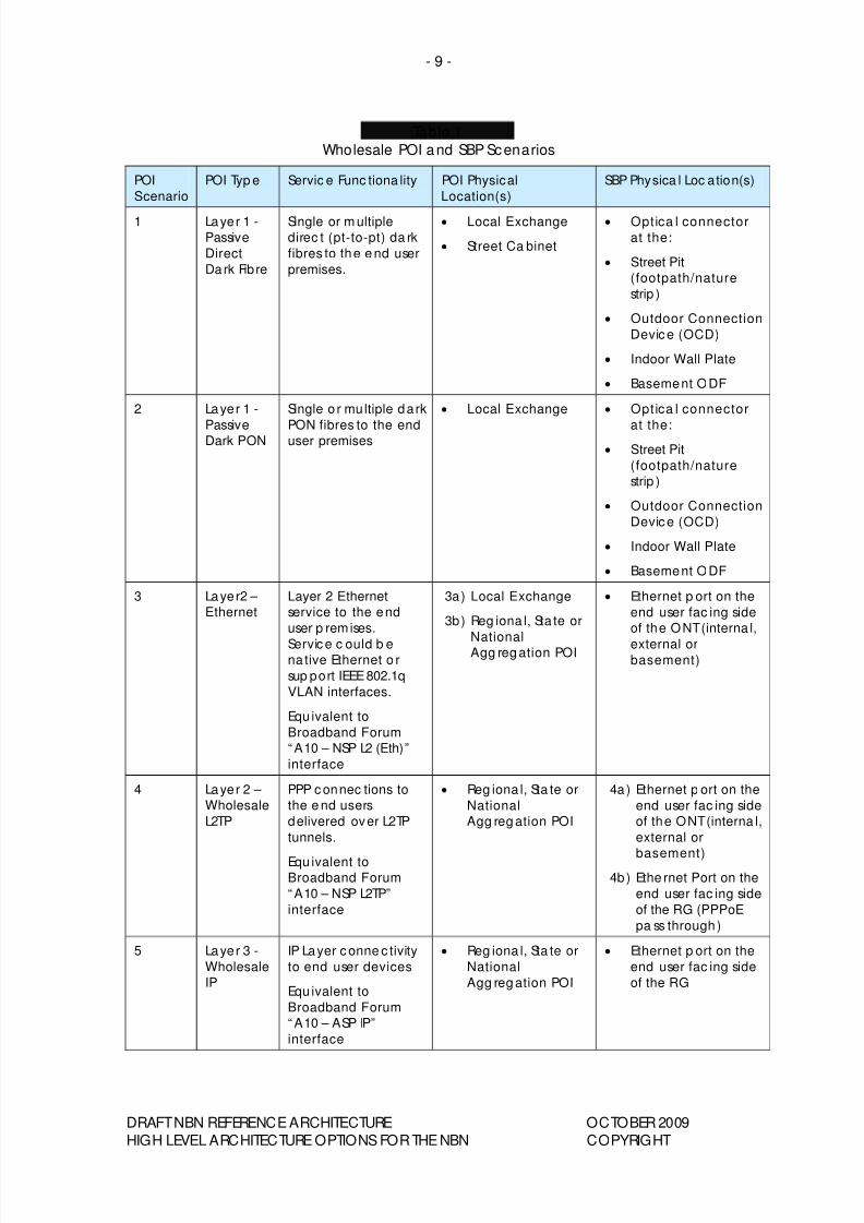
The service func tiona lity of ea ch scenario is summarised in Tab le 1 below.
Figure 3
Wholesale Point o f Interconne c t and Servic e Bounda ry Point Scena rios - FTTP Ac cess
DRAFT NBN REFERENCE ARCHITECTURE OCTOBER 2009
HIGH LEVEL ARCHITECTURE OPTIONS FOR THE NBN COPYRIGHT
8/8/2019 Draft National Broadband Network Reference Architecture Oct 2009
http://slidepdf.com/reader/full/draft-national-broadband-network-reference-architecture-oct-2009 11/26
- 9 -
Table 1
Wholesale POI and SBP Scenarios
POI
Scenario
POI Typ e Servic e Func tiona lity POI Physical
Location(s)
SBP Physica l Loc ation(s)
1 Layer 1 -
Passive
Direct
Dark Fibre
Single or m ultiple
direc t (pt-to-pt) da rk
fibres to the e nd user
premises.
• Local Exchange
• Street Ca binet
• Optica l connector
at the:
• Street Pit
(footpath/nature
strip )
• Outdoor Connection
Devic e (OCD)
• Indoor Wall Plate
• Basement ODF
2 Layer 1 -
PassiveDark PON
Single o r multiple dark
PON fibres to the enduser premises
• Local Exchange • Optica l connector
at the:• Street Pit
(footpath/nature
strip )
• Outdoor Connection
Devic e (OCD)
• Indoor Wall Plate
• Basement ODF
3 Layer2 –
Ethernet
Layer 2 Ethernet
service to the end
user p remises.
Servic e c ould b ena tive Ethernet o r
sup port IEEE 802.1q
VLAN interfaces.
Equ ivalent to
Broadband Forum
“ A10 – NSP L2 (Eth)”
interface
3a) Local Exchange
3b) Reg iona l, Sta te or
NationalAgg reg ation POI
• Ethernet p ort on the
end user fac ing side
of the ONT (interna l,
external orbasement)
4 Layer 2 –
Wholesale
L2TP
PPP c onnec tions to
the e nd users
delivered over L2TP
tunnels.
Equ ivalent toBroadband Forum
“ A10 – NSP L2TP”
interface
• Reg iona l, Sta te or
National
Agg reg ation POI
4a ) Ethernet p ort on the
end user fac ing side
of the ONT (interna l,
external or
basement)4b ) Ethe rnet Port on the
end user fac ing side
of the RG (PPPoE
pa ss through) 5 Layer 3 -
Wholesale
IP
IP Layer c onne c tivity
to end user devices
Equ ivalent to
Broadband Forum
“ A10 – ASP IP”
interface
• Reg iona l, Sta te or
National
Agg reg ation POI
• Ethernet p ort on the
end user fac ing side
of the RG
DRAFT NBN REFERENCE ARCHITECTURE OCTOBER 2009
HIGH LEVEL ARCHITECTURE OPTIONS FOR THE NBN COPYRIGHT
8/8/2019 Draft National Broadband Network Reference Architecture Oct 2009
http://slidepdf.com/reader/full/draft-national-broadband-network-reference-architecture-oct-2009 12/26
- 10 -
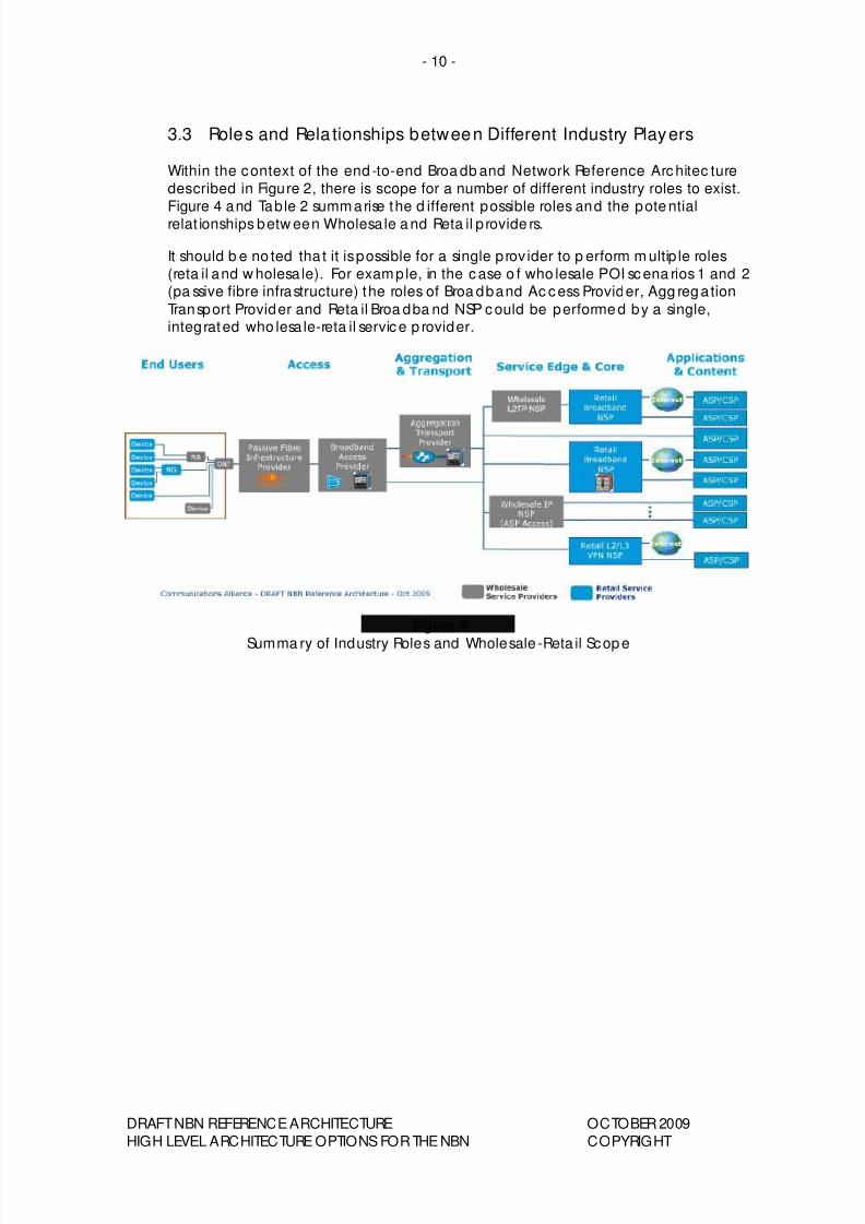
3.3 Roles and Rela tionships between Different Industry Players
Within the context of the end -to-end Broa db and Network Reference Architec ture
described in Figure 2, there is scope for a number of different industry roles to exist.
Figure 4 and Table 2 summ arise the d ifferent possible roles and the pote ntial
relat ionships betw een Wholesa le a nd Reta il p rovide rs.
It should b e no ted tha t it is possible for a single p rov ider to p erform m ultip le roles
(reta il and w holesa le). For example, in the case o f who lesale POI scena rios 1 and 2(pa ssive fibre infrastructure) the roles of Broa dband Ac cess Provider, Agg reg ation
Transport Provider and Reta il Broa dba nd NSP could be performe d by a single,integrated who lesa le-reta il service p rovider.
Figure 4
Summa ry of Industry Roles and Wholesale -Reta il Scop e
DRAFT NBN REFERENCE ARCHITECTURE OCTOBER 2009
HIGH LEVEL ARCHITECTURE OPTIONS FOR THE NBN COPYRIGHT
8/8/2019 Draft National Broadband Network Reference Architecture Oct 2009
http://slidepdf.com/reader/full/draft-national-broadband-network-reference-architecture-oct-2009 13/26
- 11 -
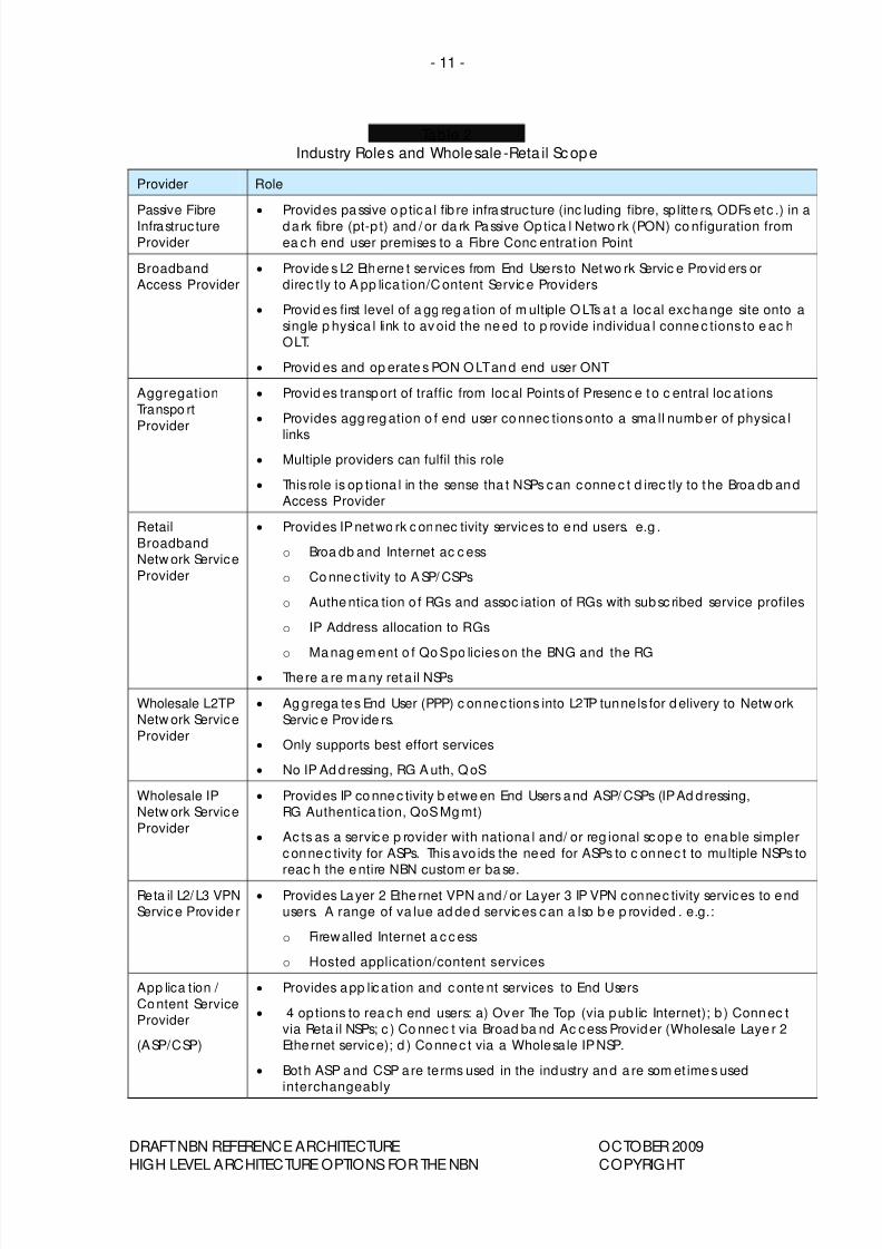
Table 2
Industry Roles and Wholesale -Reta il Scope
Provider Role
Passive Fibre
Infrastruc ture
Provider
• Provides passive o ptica l fib re infrastruc ture (inc luding fibre, sp litte rs, ODFs etc .) in a
da rk fibre (pt-p t) and / or da rk Passive Op tica l Netwo rk (PON) co nfiguration from
ea c h end user premises to a Fibre Conc entrat ion Point
Broadband
Access Provider
• Provide s L2 Etherne t services from End Users to Netwo rk Servic e Provid ers or
direc tly to A pp lica tion/C ontent Servic e Providers
• Provid es first level of a gg reg a tion of m ultiple O LTs a t a loc al exc hange site onto a
single p hysica l link to av oid the ne ed to p rovide individua l conne c tions to e ac h
OLT.
• Provid es and op erate s PON O LT and end user ONT
Aggregation
Transpo rt
Provider
• Provid es transport of traffic from loc al Points of Presenc e to c entral loc at ions
• Provides agg reg ation o f end user co nnec tions onto a sma ll numb er of physica l
links
• Multiple providers can fulfil this role
• This role is op tiona l in the sense tha t NSPs c an conne c t d irec tly to the Broa db and
Access Provider
Retail
Broadband
Netw ork Service
Provider
• Provides IP netwo rk c onnec tivity services to end users. e.g .
o Broa db and Internet ac c ess
o Co nnec tivity to A SP/ CSPs
o Authe ntica tion o f RGs and assoc iation of RGs with subsc ribed service profiles
o IP Address allocation to RGs
o Ma nag em ent o f Qo S po licies on the BNG and the RG• There a re many reta il NSPs
Wholesale L2TP
Netw ork Service
Provider
• Ag grega tes End User (PPP) c onnec tions into L2TP tunne ls for d elivery to Netw ork
Servic e Prov ide rs.
• Only supports best effort services
• No IP Ad dressing, RG A uth, Q oS
Wholesale IP
Netw ork Service
Provider
• Provides IP co nnec tivity b etwe en End Users and ASP/ CSPs (IP Ad dressing,
RG Authentica tion, QoS Mg mt)
• Ac ts as a servic e p rovider with nationa l and/ or reg ional sc op e to ena ble simpler
c onnec tivity for ASPs. This avo ids the need for ASPs to c onnec t to multiple NSPs to
reac h the e ntire NBN custom er ba se.Reta il L2/ L3 VPN
Service Prov ide r
• Provides Layer 2 Ethe rnet VPN and / or Layer 3 IP VPN connec tivity services to end
users. A range of va lue ad de d servic es c an a lso b e p rovided . e.g.:
o Firewalled Internet a c c ess
o Hosted application/content services
App lica tion /
Content Service
Provider
(ASP/CSP)
• Provides app lic a tion and c onte nt services to End Users
• 4 op tions to rea c h end users: a) Over The Top (via pub lic Internet); b ) Connec t
via Reta il NSPs; c ) Co nnec t via Broad ba nd Ac c ess Provider (Wholesale Laye r 2
Ethe rnet service); d ) Connec t via a Wholesa le IP NSP.
• Both ASP and CSP are terms used in the industry and a re som et imes used
interchangeably
DRAFT NBN REFERENCE ARCHITECTURE OCTOBER 2009
HIGH LEVEL ARCHITECTURE OPTIONS FOR THE NBN COPYRIGHT
8/8/2019 Draft National Broadband Network Reference Architecture Oct 2009
http://slidepdf.com/reader/full/draft-national-broadband-network-reference-architecture-oct-2009 14/26
- 12 -
3.4 Rela tionship between CPE and Reta il/ Wholesale providers
As desc ribed in sec tion 3.3, a range of d ifferent industry playe rs will provide
wholesa le and reta il services in the NBN environme nt. This sec tion d escribes the
relat ionship betw een the va rious types of CPE req uired to d eliver broadband IP
services and the who lesa le a nd reta il service provide rs of these services.
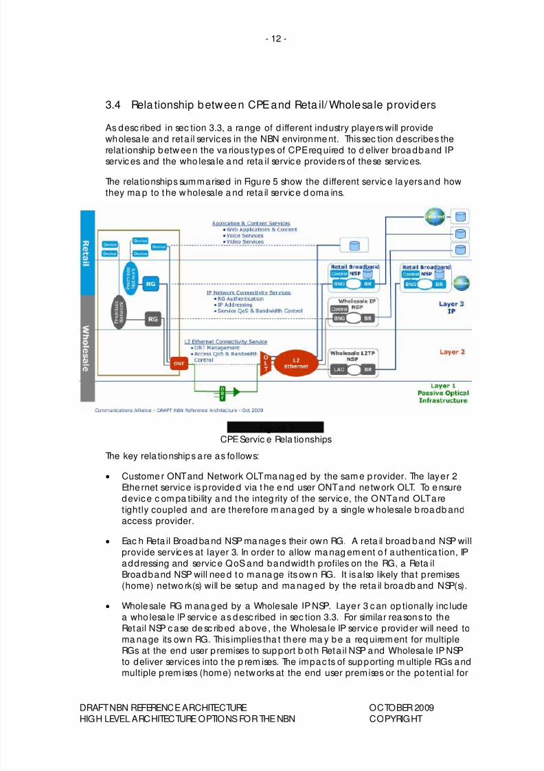
The relationships summarised in Figure 5 show the d ifferent service layers and howthey ma p to the w holesale a nd reta il service d oma ins.
Figure 5
CPE Servic e Rela tionships
The key rela tionships a re as fo llows:
• Custome r ONT and Network OLT ma nag ed by the sam e p rovider. The layer 2
Ethe rnet service is p rovide d via t he e nd user ONT and network OLT. To e nsure
device c om pa tibility and the integ rity of the service, the ONT and OLT are
tightly coupled and are therefore m ana ged by a single w holesale b roa db and
access provider.
• Eac h Reta il Broad ba nd NSP ma nages their own RG. A reta il broad band NSP willprovide services at layer 3. In order to allow ma nag ement o f authentica tion, IP
addressing and service QoS and bandwidth p rofiles on the RG, a Reta il
Broadband NSP will nee d to mana ge its ow n RG. It is a lso likely that p remises
(home) netwo rk(s) will be setup and ma nag ed by the reta il broa db and NSP(s).
• Wholesale RG m ana ged by a Wholesale IP NSP. Laye r 3 can op tionally inc lude
a who lesa le IP service as desc ribed in sec tion 3.3. For similar reasons to the
Retail NSP case de sc ribed above , the Wholesa le IP service p rovider will need to
ma nage its own RG. This implies tha t there ma y be a req uirement for multiple
RGs at the end user p remises to support b oth Reta il NSP and Wholesa le IP NSP
to deliver services into the p rem ises. The impac ts of supporting m ultiple RGs and
multiple p remises (home) ne tworks at the end user premises or the po tent ial for
DRAFT NBN REFERENCE ARCHITECTURE OCTOBER 2009
HIGH LEVEL ARCHITECTURE OPTIONS FOR THE NBN COPYRIGHT
8/8/2019 Draft National Broadband Network Reference Architecture Oct 2009
http://slidepdf.com/reader/full/draft-national-broadband-network-reference-architecture-oct-2009 15/26
- 13 -
delivering a ll services through a single reta il NSP RG a nd premises (home )
netw ork needs further considerat ion.
• End de vices may or may not be manag ed a s pa rt of the applica tion service.
The a pp lication layer provide s ap plicat ion a nd content servic es to end users
such as voice and video services and web ba sed ap plicat ions and content.The end d evices used to a ccess these services ma y or may no t be p rovided
and mana ged as pa rt of the servic e b eing provided , depe nding o n the
application.
DRAFT NBN REFERENCE ARCHITECTURE OCTOBER 2009
HIGH LEVEL ARCHITECTURE OPTIONS FOR THE NBN COPYRIGHT

8/8/2019 Draft National Broadband Network Reference Architecture Oct 2009
http://slidepdf.com/reader/full/draft-national-broadband-network-reference-architecture-oct-2009 16/26
- 14 -
4 BROADBAND NETWORK REFERENCE ARCHITECTURE –
WIRELESS/ SATELLITE ACCESS
There are two a lterna tive architec tures for p rovid ing broadband services ove r
wireless or sa tellite a ccess, dep end ing on the capa b ilities provide d b y thewireless/ sa te llite access netwo rk.
Currently, wireless and sa tellite netw orks typ ica lly p rovide layer 3 IP connec tivity to
end users. While th is is appropria te fo r p roviding reta il ac cess services, the preferedindustry ap proa ch for wholesale a ccess is to use laye r 2 ac cess connec tivity. This
a lso a ligns with the a pproach for FTTP access. How ever, laye r 2 connec tivitysolutions require development from wireless and satellite vendors.
This sec tion d esc ribes both layer 2 and laye r 3 op tions.
4.1 Option 1: Layer 2 Ethernet Acc ess
The end -to-end netwo rk architec ture c an b e seg regated into a num be r of
func tiona l dom ains as show n in Figure 6.
Figure 6
Network Reference Architec ture – Wireless/ Sate llite Layer 2 Ethernet
4.1.1 Key Network Doma ins and Func tions
The fo llow ing sec tions desc ribe the key netw ork func tions in eac h of the netw ork
domains.
4.1.1.1 End User Domain
End users will be located in residential and non-residential premises and also in non-premises based loca tions such a s pub lic roa d infrastructure (traffic cont rol system s,
street lights, etc .).
DRAFT NBN REFERENCE ARCHITECTURE OCTOBER 2009
HIGH LEVEL ARCHITECTURE OPTIONS FOR THE NBN COPYRIGHT
8/8/2019 Draft National Broadband Network Reference Architecture Oct 2009
http://slidepdf.com/reader/full/draft-national-broadband-network-reference-architecture-oct-2009 17/26
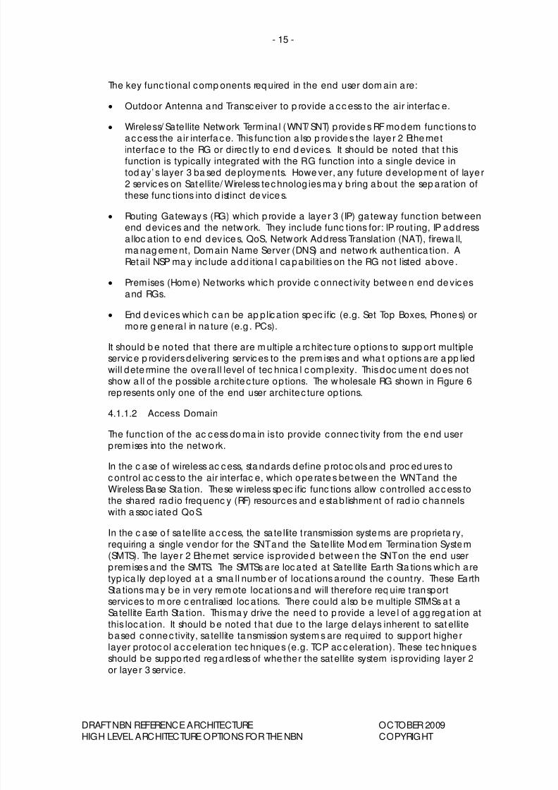
- 15 -
The key func tional comp onents req uired in the end user dom ain a re:
• Outdoor Antenna and Transceiver to p rovide a cc ess to the air interfac e.
• Wireless/ Satellite Network Termina l (WNT/ SNT) provide s RF mo dem func tions to
access the a ir interface. This func tion a lso p rovide s the laye r 2 Ethe rnetinterface to the RG or direc tly to end d evices. It should be noted that this
function is typically integrated with the RG function into a single device in
tod ay’ s layer 3 ba sed de ployments. Howe ver, any future development of laye r
2 services on Satellite/ Wireless technolog ies ma y b ring about the sep arat ion of
these func tions into d istinct de vice s.
• Routing Gateways (RG) which p rovide a laye r 3 (IP) ga teway func tion betweenend devices and the netw ork. They inc lude func tions for: IP rout ing, IP address
a lloc ation to end dev ice s, QoS, Network Address Translat ion (NAT), firewa ll,
ma nag eme nt, Domain Name Server (DNS) and netwo rk authentica tion. A
Retail NSP ma y inc lude a dd itiona l ca pabilities on the RG no t listed above .
• Premises (Hom e) Networks which provide c onnect ivity betwee n end de vices
and RGs.
• End d evices which can be ap p lica tion spec ific (e.g. Set Top Boxes, Phone s) or
mo re g ene ra l in na ture (e.g . PCs).
It should b e no ted that there are m ultiple a rchitec ture o ptions to supp ort multipleservice p roviders delivering services to the p rem ises and wha t op tions a re a pp lied
will dete rmine the ove ra ll level of tec hnica l complexity. This doc ume nt does not
show a ll of the p ossible a rchitec ture op tions. The w holesale RG shown in Figure 6
rep resents only one of the end user architec ture op tions.
4.1.1.2 Access Domain
The func tion of the ac cess do ma in is to provide connec tivity from the e nd user
premises into the netwo rk.
In the c ase o f wireless ac cess, sta ndards define p rotoc ols and proc ed ures to
c ontrol ac cess to the air interfac e, which ope rate s be tween the WNT and the
Wireless Base Sta tion. These w ireless spec ific func tions allow controlled access to
the shared rad io freq uenc y (RF) resources and e stab lishment o f rad io channels
with a ssoc iated QoS.
In the c ase o f sa te llite a ccess, the sa te llite t ransmission systems are p roprieta ry,
requiring a single vendor for the SNT and the Sate llite Mod em Termina tion System
(SMTS). The laye r 2 Ethe rnet service is p rovide d between the SNT on the end userpremises and the SMTS. The SMTSs are loc a ted at Sa te llite Earth Sta tions which a re
typ ica lly dep loyed a t a sma ll numb er of locat ions a round the c ount ry. These Earth
Sta tions ma y be in very rem ote locat ions and will therefore req uire t ransport
services to m ore c entralised loc ations. There could a lso b e multiple STMSs a t aSatellite Earth Sta tion. This ma y drive the need to p rovide a leve l of a gg reg at ion at
this locat ion. It should b e noted tha t due t o the large d elays inherent to satellitebased connec tivity, sa tellite tansmission system s are req uired to support highe r
layer protoc ol a ccelerat ion tec hniques (e.g. TCP ac celerat ion). These tec hniques
should be suppo rted reg ard less of whe ther the satellite system is p roviding layer 2
or laye r 3 service.
DRAFT NBN REFERENCE ARCHITECTURE OCTOBER 2009
HIGH LEVEL ARCHITECTURE OPTIONS FOR THE NBN COPYRIGHT
8/8/2019 Draft National Broadband Network Reference Architecture Oct 2009
http://slidepdf.com/reader/full/draft-national-broadband-network-reference-architecture-oct-2009 18/26
- 16 -
4.1.1.3 Aggregation & Transpo rt Doma in
In the c ase o f wireless access, the Aggregation and Transport doma in p rovide sEthe rnet t ransmission from d istributed wireless base sta tions back to centrally
loc ate d Wireless Ga teways. It should be noted that there may be spe c ific
req uirements plac ed on the Ethernet a gg regat ion a nd transpo rt netw ork tosupport wireless (e.g . support fo r Qo S and sync hronisation o ver Ethe rnet).
In the case of satellite ac cess, the Agg regat ion and Transpo rt d oma in p rovides
Ethe rnet transmission from Sate llite Earth Sta tions, which ma y be loc a ted in remo te
areas, ba ck to more centralised loc ations.
4.1.1.4 Service Edge & Core Domain
In the c ase o f wireless ac cess, sta ndards define p rotoc ols and proc ed ures to
ma nage user connec tions ac ross the w ireless do ma in between the Wireless
Ga tewa y and the WNT. The layer 2 Ethe rnet service leve rages these wireless
proto cols and is p rovided betw een the WNT on the end user premises and the
Wireless Ga tew ay. The Wireless Ga tew ays are t ypica lly located in ce ntralised
locations in metropolitan areas.
In the c ase o f sate llite access, the sate llite transmission system b etwe en the Sate llite
Mo dem Transmission Syste m (SMTS) and the SNT is p rop rieta ry. The laye r 2 Ethernet
servic e is p rovided betwee n the SNT and the SMTS. The SMTSs are loc a ted a tSatellite Earth Sta tions which are typ ica lly de ployed a t a sma ll numb er of loc a tions
around the c ount ry. It should b e noted tha t these Earth Sta tions ma y be in veryrem ote locat ions and will therefore req uire t ransport services to mo re c ent ralised
locations.
The NSP func tions in this domain have the sam e func tiona lity a nd access the
Ethe rnet service in the same wa y as the FTTP case d esc ribed in sec tion 3.1.4. Inadd ition to these func tions, suppo rt for QoS ove r wireless access will req uire cont rol
plane interac tion be tween the wireless ga teway and the wholesale/ reta il NSP due
to the d ynamic na ture of rad io bea rer estab lishment/ tea rdo wn.
4.1.1.5 App lication & Co ntent Domain
See sec tion 3.1.5.
4.1.2 Wholesale Point o f Interconnec t a nd Service Boundary Point Scena rios
Within the context of the end -to-end Broa db and Network Reference Architec ture
described in section 4.1.1, there a re a range of p otentia l Wholesa le POIs and
c orrespond ing Servic e Bound ary Points (SBP). These Who lesale POI and SBPscena rios can b e d efined by the service func tionality ava ilab le at the interfac e,
their loc ation and the am ount of ag gregation they provide.
The po ssible loc at ions in the netw ork hierarchy o f the Wholesa le POI and
correspond ing SBP scena rios are show n in Figure 7. Each POI scenario ha s acorrespond ing SBP scenario. The numb ering of the POI and SBP scenarios indic a tes
the a llow ab le POI and SBP pa irings. The service func tiona lity o f ea ch scena rio is
summa rised in Tab le 3.
DRAFT NBN REFERENCE ARCHITECTURE OCTOBER 2009
HIGH LEVEL ARCHITECTURE OPTIONS FOR THE NBN COPYRIGHT
8/8/2019 Draft National Broadband Network Reference Architecture Oct 2009
http://slidepdf.com/reader/full/draft-national-broadband-network-reference-architecture-oct-2009 19/26
- 17 -
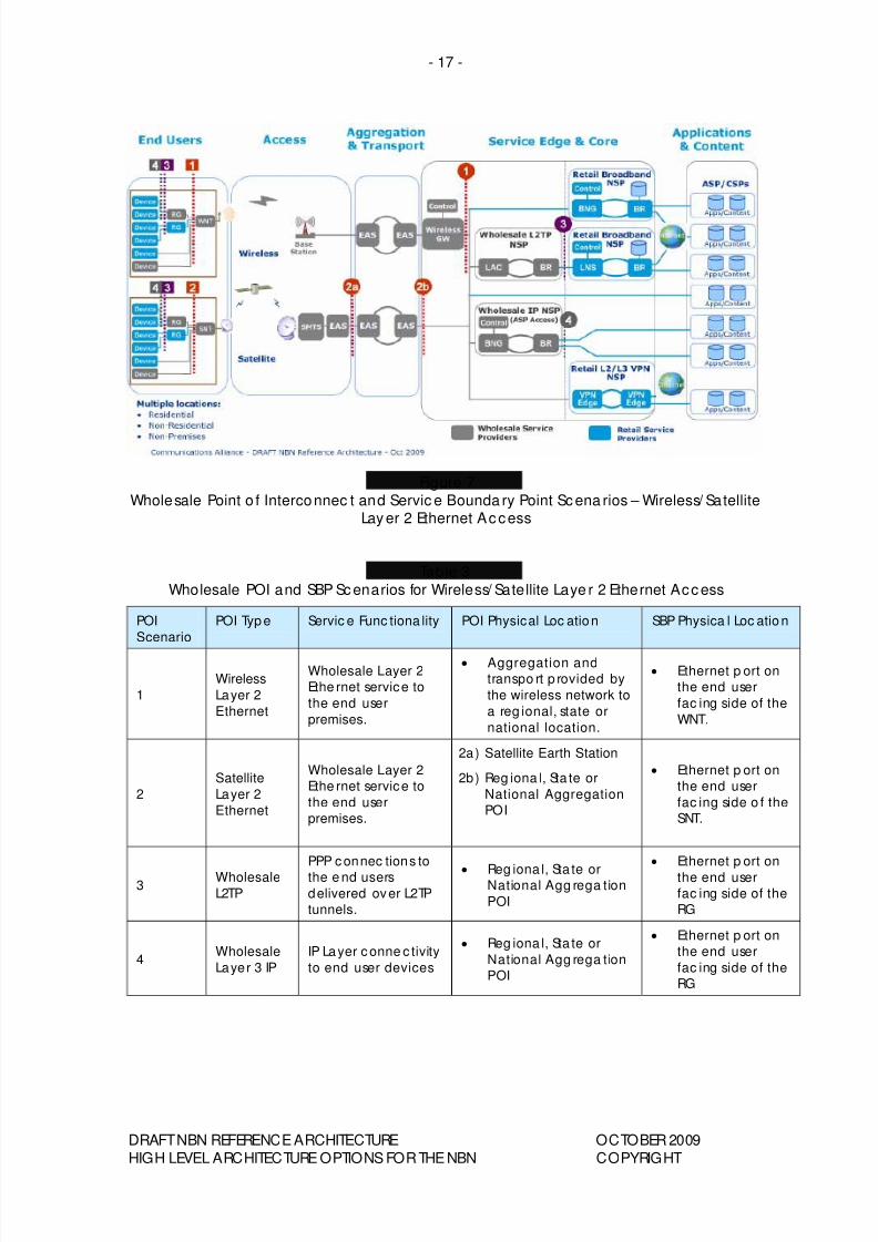
Figure 7
Wholesale Point o f Interconnec t and Servic e Bounda ry Point Scena rios – Wireless/ SatelliteLayer 2 Ethernet Access
Table 3
Wholesale POI and SBP Scenarios for Wireless/ Satellite Laye r 2 Ethernet Access
POI
Scenario
POI Typ e Servic e Func tiona lity POI Physical Loc ation SBP Physica l Loc atio n
1
Wireless
Layer 2
Ethernet
Wholesale Layer 2
Ethe rnet service to
the end user
premises.
• Aggregation and
transpo rt p rovided by
the wireless network to
a reg ional, state or
national location.
• Ethernet p ort on
the end user
fac ing side of the
WNT.
2
Satellite
Layer 2
Ethernet
Wholesale Layer 2
Ethe rnet service to
the end user
premises.
2a) Satellite Earth Station
2b) Reg iona l, Sta te or
National Aggregation
POI
• Ethernet p ort on
the end user
fac ing side o f the
SNT.
3Wholesale
L2TP
PPP c onnec tions to
the e nd users
delivered over L2TP
tunnels.
• Reg iona l, Sta te orNational Agg rega tion
POI
• Ethernet p ort on
the end user
fac ing side of the
RG
4Wholesale
Layer 3 IP
IP Layer c onne c tivity
to end user devices
• Reg iona l, Sta te or
National Agg rega tion
POI
• Ethernet p ort on
the end user
fac ing side of the
RG
DRAFT NBN REFERENCE ARCHITECTURE OCTOBER 2009
HIGH LEVEL ARCHITECTURE OPTIONS FOR THE NBN COPYRIGHT
8/8/2019 Draft National Broadband Network Reference Architecture Oct 2009
http://slidepdf.com/reader/full/draft-national-broadband-network-reference-architecture-oct-2009 20/26
- 18 -
4.2 Option 2: Wireless/ Satellite Layer 3 IP Ac cess
The fo llow ing sec tions desc ribe the key netw ork func tions in eac h of the ne twork
domains.
4.2.1 Key Network Doma ins and Func tions
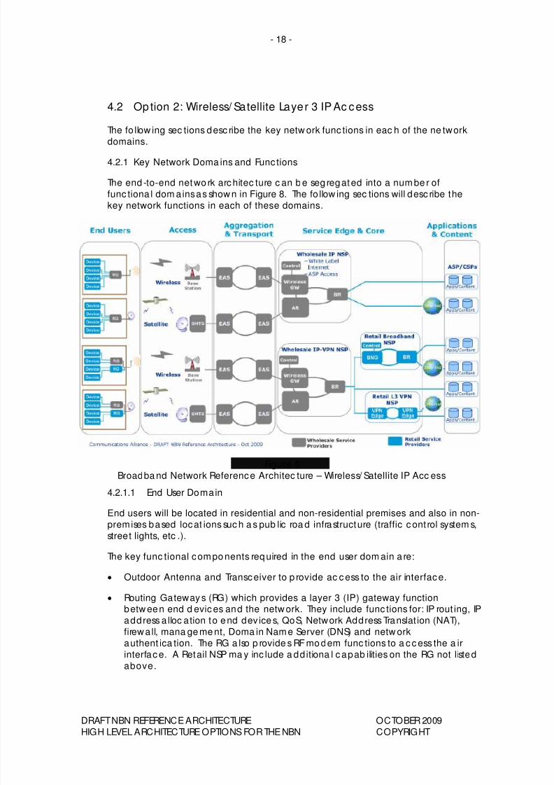
The end -to-end netwo rk architec ture c an b e seg regated into a num be r of
func tiona l dom ains as show n in Figure 8. The fo llow ing sec tions will desc ribe the
key network functions in each of these domains.
Figure 8
Broadba nd Network Reference Architec ture – Wireless/ Satellite IP Acc ess
4.2.1.1 End User Domain
End users will be located in residential and non-residential premises and also in non-
premises based locat ions suc h a s pub lic roa d infrastructure (traffic cont rol system s,
street lights, etc .).
The key func tional compo nents req uired in the end user dom ain a re:
• Outdoor Antenna and Transceiver to p rovide ac cess to the air interface.
• Routing Gateways (RG) which provides a layer 3 (IP) gateway functionbetw een end d evices and the netw ork. They include func tions for: IP rout ing, IP
address a lloc ation to end dev ice s, QoS, Network Address Translat ion (NAT),
firewa ll, mana ge me nt, Doma in Name Server (DNS) and netw ork
authent ica tion. The RG a lso p rovide s RF mo dem func tions to a ccess the a ir
interface. A Retail NSP ma y inc lude a dd itiona l capab ilities on the RG not listed
above.
DRAFT NBN REFERENCE ARCHITECTURE OCTOBER 2009
HIGH LEVEL ARCHITECTURE OPTIONS FOR THE NBN COPYRIGHT
8/8/2019 Draft National Broadband Network Reference Architecture Oct 2009
http://slidepdf.com/reader/full/draft-national-broadband-network-reference-architecture-oct-2009 21/26
- 19 -
• Premises (Hom e) Networks which provide c onnect ivity betwee n end de vices
and RGs.
• End d evices which can be app licat ion spec ific (e.g. Set Top Boxes, Phone s) or
mo re g ene ra l in na ture (e.g . PCs).
It should b e no ted that there are m ultiple a rchitec ture o pt ions to supp ort multiple
service p roviders delivering services to the p rem ises and wha t opt ions a re a pplied
will dete rmine the ove ra ll level of tec hnica l complexity. This doc ume nt does not
show a ll of the p ossible a rchitec ture op tions. The w holesale RG shown in Figure 8
rep resents only one of the end user arch itec ture op tions.
4.2.1.2 Access Domain
The func tion of the ac cess do ma in is to provide connec tivity from the e nd user
premises into the netw ork.
In the c ase o f wireless ac cess, sta ndards define p rotoc ols and proc ed ures to
control access to t he a ir interfac e, which o pe rate s be tween the RG (RF mode m)and the Wireless Base Sta tion. These wireless spec ific func tions allow controlled
ac cess to the sha red radio freq uenc y (RF) resources and esta blishme nt o f rad io
channels with assoc iated QoS.
In the case o f sa te llite a ccess, the sa te llite transmission systems are p roprieta ry,
req uiring a single vendor for the RG and the Satellite Modem Termination System(SMTS). The SMTSs are loc ate d a t Sa te llite Earth Sta tions which a re typ ica lly
de ployed at a sma ll number of loca tions around the c ountry. It should be no ted
tha t the se Earth Sta tions ma y be in very remote loca tions and will therefore require
transport services to m ore c ent ra lised locat ions.
4.2.1.3 Aggregation & Transpo rt Doma in
In the c ase o f wireless access, the Aggregation and Transport doma in p rovide s
Ethe rnet t ransmission from d istributed wireless base sta tions back to centrally
loc ate d Wireless Ga tewa ys. It should be note d that there ma y be spe c ific
req uirements plac ed on the Ethernet a gg regat ion a nd transpo rt netw ork to
support wireless (e.g . support fo r Qo S and sync hronisation o ver Ethe rnet).
In the case of satellite ac cess, the Agg regat ion and Transpo rt d oma in p rovides
Ethe rnet transmission from Sate llite Earth Sta tions, which ma y be loc a ted in remo te
areas, ba ck to more centralised loc ations.
The c urrent a nd future trend for providing aggregat ion and transport networks is to
use Ethernet b ased ag grega tion and transpo rt tec hnology.
4.2.1.4 Service Edge & Core Domain
In the case o f Wireless/ Sate llite IP access two a ccess mo dels can be suppo rted .
The standard app roa ch is to p rovide Wholesale IP access. In this case, the
Wholsa le IP network provides a ll of the Netw ork Service Prov ider (NSP) ne twork
func tions and reta il servic es are p rovide d v ia a resa le mode l (so c a lled White Label
NSP). This sc ena rio a lso supports d irec t a ccess to the Wholesa le IP service b y
ASP/CSPs.
The alternat ive approa ch is for the wireless/ satellite netw ork to p rovide Wholesale
IP-VPN ac cess. This a llow s reta il b roadband NSPs to p rovide som e ne twork
DRAFT NBN REFERENCE ARCHITECTURE OCTOBER 2009
HIGH LEVEL ARCHITECTURE OPTIONS FOR THE NBN COPYRIGHT
8/8/2019 Draft National Broadband Network Reference Architecture Oct 2009
http://slidepdf.com/reader/full/draft-national-broadband-network-reference-architecture-oct-2009 22/26
- 20 -
func tiona lity. In this case, the w ireless network provide s IP-VPN co nnec tivity
be tween each reta il b roa dband NSP to the e nd users. The retail b roa dband NSP
provide s a similar set of subsc riber ma nage ment func tions as desc ribed in sec tion
3.1.4. This approach also sup ports reta il layer 3 VPN NSPs. While th is approa ch is
not spec ified in sta ndards, it is supported b y som e wireless vendors. Sup port bysate llite vendors ma y require de velopm ent.
It should be noted that Wholesale IP or IP-VPN Access implies a single national/
reg iona l wholesale prov ider per Wireless/ Sate llite ac cess netwo rk.
4.2.1.5 App lication & Content Doma in
See sec tion 3.1.5.
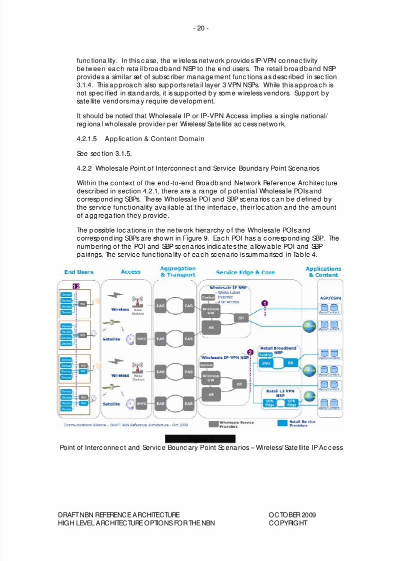
4.2.2 Wholesale Point o f Interconnec t and Service Bounda ry Point Scena rios
Within the context of the end -to-end Broa db and Network Reference Architec ture
described in section 4.2.1, there a re a range of p otentia l Wholesa le POIs and
correspond ing SBPs. These Wholesale POI and SBP scena rios can be d efined bythe service func tionality ava ilable at the interfac e, their loc ation and the am ount
of a gg rega tion they p rovide.
The p ossible loc a tions in the ne twork hierarchy o f the Wholesa le POIs andcorrespond ing SBPs are shown in Figure 9. Each POI has a c orrespond ing SBP. The
numbering of the POI and SBP scenarios indic a tes the a llow able POI and SBPpa irings. The service func tiona lity o f ea ch scenario is summa rised in Tab le 4.
Figure 9Point of Interconnec t and Service Bound ary Point Scena rios – Wireless/ Sate llite IP Ac cess
DRAFT NBN REFERENCE ARCHITECTURE OCTOBER 2009
HIGH LEVEL ARCHITECTURE OPTIONS FOR THE NBN COPYRIGHT
8/8/2019 Draft National Broadband Network Reference Architecture Oct 2009
http://slidepdf.com/reader/full/draft-national-broadband-network-reference-architecture-oct-2009 23/26
- 21 -
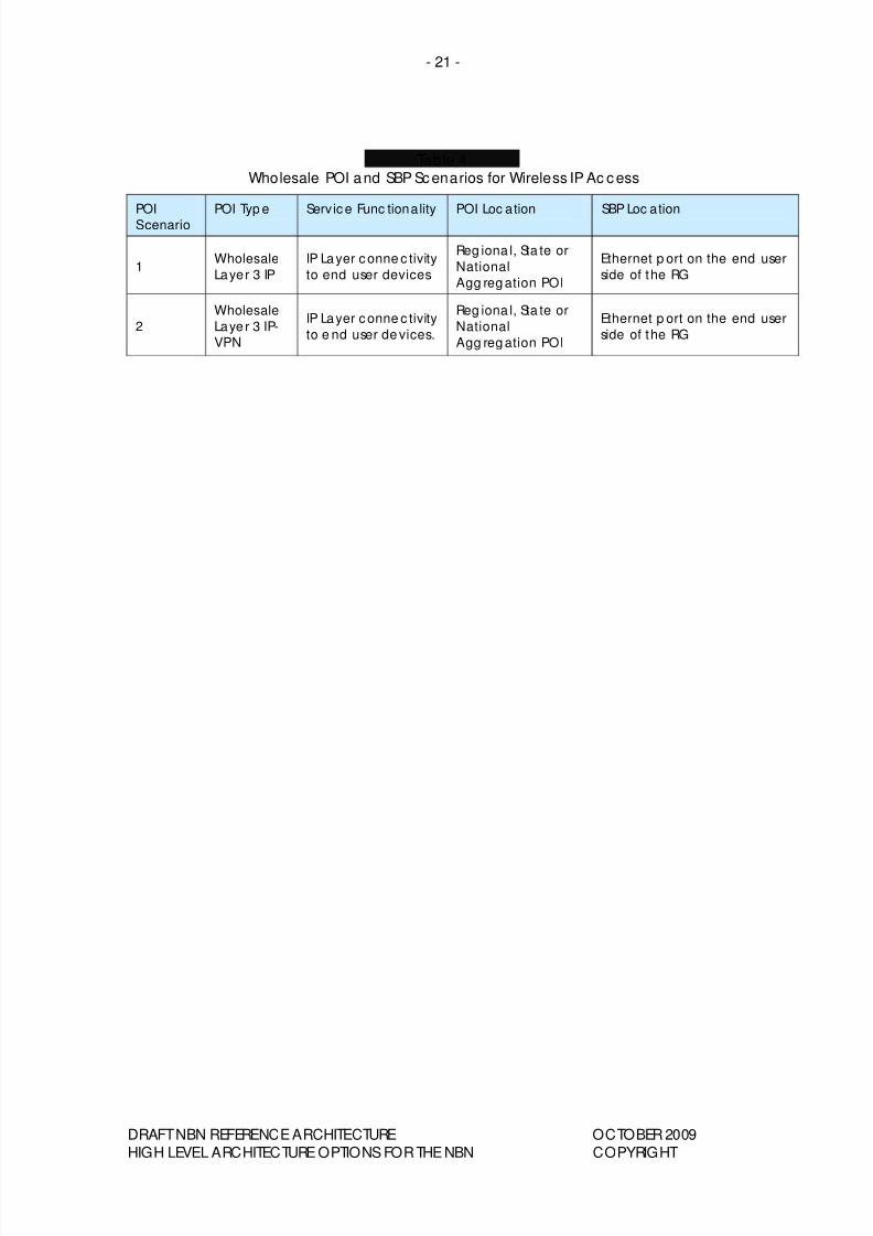
Table 4
Wholesale POI and SBP Scenarios for Wireless IP Ac cess
POI
Scenario
POI Typ e Servic e Func tionality POI Loc ation SBP Loc ation
1Wholesale
Layer 3 IP
IP Layer c onne c tivity
to end user devices
Reg iona l, Sta te or
National
Agg reg ation POI
Ethernet p ort on the end user
side of the RG
2
Wholesale
Layer 3 IP-
VPN
IP Layer c onne c tivity
to e nd user de vices.
Reg iona l, Sta te or
National
Agg reg ation POI
Ethernet p ort on the end user
side of the RG
DRAFT NBN REFERENCE ARCHITECTURE OCTOBER 2009
HIGH LEVEL ARCHITECTURE OPTIONS FOR THE NBN COPYRIGHT
8/8/2019 Draft National Broadband Network Reference Architecture Oct 2009
http://slidepdf.com/reader/full/draft-national-broadband-network-reference-architecture-oct-2009 24/26
- 22 -
5 FURTHER CONSIDERATIONS
Eac h document p rod uced as pa rt of the Com munica tions Allianc e NBN projec t
has a sec tion ded ica ted to the spe c ific issues listed below. The p urpose o f these
sections is to prompt the contributors, participants and persons commenting on thedoc uments to ident ify issues or considerations releva nt to the sec tion. These
sec tions are completed ba sed on information ava ilab le at the t ime o f writing and
ma y change over time.
5.1 Sustainability
The susta inab ility of the Broa dband Network Referenc e Architec ture op tions listed
in this doc ume nt have no t yet b een assessed .
However, co ntributo rs and pe rsons commenting on this do cument are
enc ourag ed to adv ise o f any issues reg ard ing the susta inab ility of the o p tions a t
the ea rliest possible opp ortunity.
5.2 Robustness
The rob ustness of the Broa dband Network Referenc e Architec ture op tions listed in
this do cument have not ye t b een assessed .
However, co ntributo rs and pe rsons commenting on this do cument are
enc ourag ed to adv ise o f any issues reg ard ing the rob ustness of the op tions a t the
earliest possible opportunity.
5.3 Security
The sec urity of the Broa db and Network Refe renc e Architec ture op tions listed in thisdo cument ha ve not yet be en a ssessed .
However, co ntributo rs and pe rsons commenting on this do cument are
encouraged to advise of any issues regarding the security of the options at the
earliest possible opportunity.
5.4 IPv6
The c ompatibility of the Broa dband Netwo rk Referenc e Architec ture op tions listed
in this doc ument ha ve not yet been a ssessed in light o f IPv6.
However, co ntributo rs and pe rsons commenting on this do cument areenc ourag ed to adv ise o f any issues reg ard ing IPv6 at the ea rliest p ossible
opportunity.
5.5 Future Proo fness
The future proofne ss of the Broa dband Netw ork Refe renc e Arch itec ture op tions
listed in this do cume nt have no t yet been assessed .
However, co ntributo rs and pe rsons commenting on this do cument are
enc ourag ed to a dv ise o f any issues reg ard ing future proofness of the op tions a t theearliest possible opportunity.
DRAFT NBN REFERENCE ARCHITECTURE OCTOBER 2009
HIGH LEVEL ARCHITECTURE OPTIONS FOR THE NBN COPYRIGHT

8/8/2019 Draft National Broadband Network Reference Architecture Oct 2009
http://slidepdf.com/reader/full/draft-national-broadband-network-reference-architecture-oct-2009 25/26
- 23 -
DRAFT NBN REFERENCE ARCHITECTURE OCTOBER 2009
HIGH LEVEL ARCHITECTURE OPTIONS FOR THE NBN COPYRIGHT
6 ABBREVIATIONS
ASP Ap plica tion Service Provide r
AR Ac c ess Route r
CSP Conten t Servic e Provider
BNG Broad ba nd Network Gatew ay
BR Border Rou ter
DNS Domain Nam e Service
EAS Ethernet Ag greg a tion Switch
FTTP Fibre to the Premises
L2TP Layer 2 Tunne lling Protoc ol
LAC L2TP Ac c ess Co nc entrator
LNS L2TP Network Server
NAT Netwo rk Ad dress Transla tion
NSP Netw ork Service Provider
NTU Netwo rk Termina tion Unit
ODF Optical Distribution Frame
ONT Op tica l Netw ork Termination
OLT Op tica l Line Termination
POI Point of Interc onnec t
PON Passive O pt ica l Netwo rkPPP Point to Point Protoc ol
QOS Qua lity of Service
RG Routing Gateway
RSP Reta il Service Provider
SBP Service Bound ary Point
SMTS Sate llite Mod em Termina tion System
SNT Sate llite Ne twork Termina l
VPN Virtual Private Network
WNT Wireless Network Termina l

8/8/2019 Draft National Broadband Network Reference Architecture Oct 2009
http://slidepdf.com/reader/full/draft-national-broadband-network-reference-architecture-oct-2009 26/26
Published b y:
COMMUNICATIONS
ALLIANCE LTD
Level 9
32 Walker Stree t
North Sydney
NSW 2060 Australia
Correspondence
PO Box 444
Milsons Point
NSW 1565
T 61 2 9959 9111
F 61 2 9954 6136
TTY 61 2 9923 1911Einfo@commsalliance .com.au
www.commsalliance.com.au
ABN 56 078 026 507
Care should be taken to
ensure the m aterial used is
from the c urrent version of
the Stand ard or Industry
Code and that it is upda ted
whenever the Standard or
Code is amended or
revised . The numbe r anddate of the Standard or
Code should therefore b e
cle arly ide ntified . If in
doubt please c ontact


![Broadband Architecture Moving to FMC...2014/01/24 · [2] MR-235 Considerations in Broadband Architecture Moving to FMC, 2011 – Describing BBF vision towards aligning the telecom](https://static.fdocuments.us/doc/165x107/5ecb29407886ea396f671541/broadband-architecture-moving-to-fmc-20140124-2-mr-235-considerations.jpg)