DRAFT - N2CKH Cyberspace QTH · DRAFT PC-ALE Radio Control Knowledge Base by N2CKH 23 OCTOBER 2010...
41
DRAFT PC-ALE Radio Control Knowledge Base by N2CKH 23 OCTOBER 2010 OVERVIEW - This document details various aspects of configuration of PC-ALE v1.073A with its main focus being CAT Radio Control support to include PTT and MUTING methods via either CAT or RS-232 signaling lines. PC-ALE runs on Windows 2000 Professional, Windows XP, Windows XP Professional, Windows Vista and Windows 7 (where in Windows 7 you MUST be logged in as Administrator when installing and where it is best to change the properties of the ALE.EXE to run as XP/SP2). There may be issues under Vista and Windows 7 if the software is installed to the default C:\Program Files\PC-ALE\ sub directory due to Anti- Virus/Malware protection features with these newer versions of Windows. An 800Mhz CPU and AC’97 Sound Device and at least one RS-232 serial port are required. A “RADIO TYPE MATRIX” is provided herein which details all “Radio Type” selections supported by PC-ALE beginning with radio type “NONE” where the radio is not under PC control and supports single channel ALE operation only, through each selection for specific make/model CAT HF SSB transceivers and receivers that are supported for full ALE operation. At last count there were 158 active “Radio Type” selections, which support 25 manufacturers of 196 known transceivers models, 85 known receiver models and 6 known models of exciters. The T-BUS Radio Type selection supports an unknown number of make/model radios from various manufacturers and other selections provide support across families of radios from some manufacturers where all the models and variations supported are not known. In addition the pairing selections for ICOM receivers and transceivers as well as older Ten Tec radios compatible with ICOM CIV as well as the same using Watkins-Johnson receivers supports a large number of pairing combinations. The Cubic and Harris receiver and exciter pairing also support a number of pairing combinations. The “TXDPULSE” selection allows for support of all radios without CAT control where if the radio provides programmable memory channel and the ability to step through them using the radio Up/Dn switches by interfacing to the RS-232 TXD Pulse line to step the memory channels UP with each channel scan step. Additional make/model radio equipments are always being added. Should your radio not be listed under either the “RADIO TYPE” or “COMMENTS” columns in the RADIO TYPE MATRIX as it is new or obscure, please contact [email protected] with the details and all documentation you may have for computer control programming. In addition, if you radio is not listed, see the section “WHAT TO DO WHEN YOUR RADIO TYPE IS NOT LISTED” to determine if there is anyway to place your radio into use until specific support is added. RADIO EMULATION - The main purpose of Radio Emulation (REM) is to support seamless ALE follow-on digital communications or ALE QSO logging via a 3 rd Party Software application. When the 3 rd Party Software also supports a using a PC Sound Device for a modem and it is desired to use same PC Sound Device as PC-ALE, a 48Khz sample rate must be used for both transmit and receive,
Transcript of DRAFT - N2CKH Cyberspace QTH · DRAFT PC-ALE Radio Control Knowledge Base by N2CKH 23 OCTOBER 2010...

DRAFT PC-ALE Radio Control
Knowledge Base
by N2CKH
23 OCTOBER 2010
OVERVIEW - This document details various aspects of configuration of PC-ALE v1.073A with its main focus being CAT Radio Control support to include PTT and MUTING methods via either CAT or RS-232 signaling lines. PC-ALE runs on Windows 2000 Professional, Windows XP, Windows XP Professional, Windows Vista and Windows 7 (where in Windows 7 you MUST be logged in as Administrator when installing and where it is best to change the properties of the ALE.EXE to run as XP/SP2). There may be issues under Vista and Windows 7 if the software is installed to the default C:\Program Files\PC-ALE\ sub directory due to Anti-Virus/Malware protection features with these newer versions of Windows. An 800Mhz CPU and AC’97 Sound Device and at least one RS-232 serial port are required. A “RADIO TYPE MATRIX” is provided herein which details all “Radio Type” selections supported by PC-ALE beginning with radio type “NONE” where the radio is not under PC control and supports single channel ALE operation only, through each selection for specific make/model CAT HF SSB transceivers and receivers that are supported for full ALE operation. At last count there were 158 active “Radio Type” selections, which support 25 manufacturers of 196 known transceivers models, 85 known receiver models and 6 known models of exciters. The T-BUS Radio Type selection supports an unknown number of make/model radios from various manufacturers and other selections provide support across families of radios from some manufacturers where all the models and variations supported are not known. In addition the pairing selections for ICOM receivers and transceivers as well as older Ten Tec radios compatible with ICOM CIV as well as the same using Watkins-Johnson receivers supports a large number of pairing combinations. The Cubic and Harris receiver and exciter pairing also support a number of pairing combinations. The “TXDPULSE” selection allows for support of all radios without CAT control where if the radio provides programmable memory channel and the ability to step through them using the radio Up/Dn switches by interfacing to the RS-232 TXD Pulse line to step the memory channels UP with each channel scan step. Additional make/model radio equipments are always being added. Should your radio not be listed under either the “RADIO TYPE” or “COMMENTS” columns in the RADIO TYPE MATRIX as it is new or obscure, please contact [email protected] with the details and all documentation you may have for computer control programming. In addition, if you radio is not listed, see the section “WHAT TO DO WHEN YOUR RADIO TYPE IS NOT LISTED” to determine if there is anyway to place your radio into use until specific support is added. RADIO EMULATION - The main purpose of Radio Emulation (REM) is to support seamless ALE follow-on digital communications or ALE QSO logging via a 3rd Party Software application. When the 3rd Party Software also supports a using a PC Sound Device for a modem and it is desired to use same PC Sound Device as PC-ALE, a 48Khz sample rate must be used for both transmit and receive,

otherwise two PC Sound Devices will be required. Another option for use of the same PC Sound Device when different sample rates are being and we are talking attended operation is to make use of the capability to release RESOURCES after the ALE link for follow-on 3rd Party Software communications where after releasing resources the 3rd Party Software can be started and then it can open the PC Sound Device as it desires, then after use the 3rd Party Software can be shut down and RESOURCES reclaimed, the problem here is the need for all the manual steps by the user. For unattended operation when the 3rd Party Software is not using a 48Khz sample rate for TX/RX a 2nd PC Sound Device in the system must be used for its modem requirements. You can also use Radio Emulation just for stand alone operation where PC-ALE acts as a CAT Radio Server to allow for 3rd Party Software control of any radio make/models otherwise not supported by the 3rd Party Software, such as the numerous Commercial, Marine and Military transceivers and receivers as well as many Amateur radios that are not commonly supported in HAM software but are found in PC-ALE. All radios supported by PC-ALE as well as PC-ALE pairing of radios are available via Radio Emulation. PC-ALE provides Radio Emulation in a manor where PC-ALE looks like either a KENWOOD or ICOM transceiver to 3rd Party Software that provides CAT control of KENWOOD or ICOM radio. PC-ALE via the Radio Emulation (REM) port supports whatever “Radio Type” is selected in PC-ALE that supports more than just radio Memory Channel operation for Frequency and Mode control. In PC-ALE there is no selection of KENWOOD or ICOM required for Radio Emulation support as they are both automatically supported. Any commands that are not legitimate KENWOOD or ICOM CAT commands are ignored. For the purpose of the 3rd Party Software when queried with ID commands, PC-ALE for KENWOOD emulation will return address ID020 to appear to be a TS-480SAT and for ICOM emulation it will return radio address 66h to appear to be an IC-746PRO/IC-7400. It does not matter to PC-ALE what KENWOOD or ICOM model is actually selected (and for ICOM the radio addressed used does not matter) in the 3rd Party Software for basic radio control features, however PC-ALE will only respond as either a TS-480 or IC-746PRO when queried and will only act on commands meant for those two models of radios. Also, it does not matter what the serial port parameters are set to either, however RTS/CTS should not be selected as they are not supported in PC-ALE for REM and will likely cause the 3rd Party Software to balk. PC-ALE has been tested with various popular HAM software, Rig Control applications, Logging applications and Digital Communications applications, to include programs that constantly request radio parameter feedback and check that a TS-480 or IC-746PRO is the radio actually being controlled. All such programs are happy with the PC-ALE Radio Emulation. However some programs can not keep up on their end when it comes to monitoring actual PC-ALE channel changes while in scanning mode. When scan rates in excess of 1 ch/sec are used, for example MixW updates its display of frequency and mode about two times a second, thus its rather poor at keeping pace beyond 1 ch/sec, Flrig can be adjusted for updates, but it too will only follow a 1 ch/sec scan rate. HRD regardless of its polling/refresh setup lags behind and at times falls way behind in frequency display and really falls behind on mode display when mixed USB/LSB channels are used. However CI-V Commander seems to have no problems keeping pace through 5 ch/sec when setup for fast enough polling. So when it comes to having a 3rd Party program monitoring PC-ALE during scanning it will depend on what program is being used and how it is configured. By design PC-ALE requires a pair of VCP ports for REM support, I recommend the use of N8VM Vcom or other such utility is used to bridge the PC-ALE and 3rd Party Software. To enabled Radio Emulation in PC-ALE a valid REM Comm Port that is not already in use must be entered. In PC-ALE the REM Port can be COM 1 thru COM 16 where whatever port is used must be entered into the N8VBvCOM.inf file as one half of the pairing and whatever port is desired for the 3rd Party Software CAT radio port needs to be entered as the other half of the pairing. For example in PC-ALE we use COM12 and in the given 3rd Party Software we used COM13 and we only wanted one set of pairs in our use of Vcom then the Number of pairs section of N8VBvCOM.inf would need to be un-remarked to read: ;Number Of Pairs ;************

PAIRS=0x01 ;PAIRS=0x02 ;PAIRS=0x03 ;PAIRS=0x04 ;PAIRS=0x05 ;PAIRS=0x06 ;PAIRS=0x07 ;PAIRS=0x08 ;PAIRS=0x09 ;PAIRS=0x0A ;NOTE: MAX is 10 pairs Also the Pair 1 section of N8VBvCOM.inf would need to look like: ;Pair 1 ;************ PORT1="COM12" PORT2="COM13" As VCP ports are being used, the serial port parameters for Radio Emulation in PC-ALE and the 3rd Party software do not have to match, however should someone desire to run the program on two different PC’s due to CPU loading or for whatever reason, then a Null Modem cable will be required and the 3rd Party software will need to be setup for 19,200 baud, No Parity, 8 data bits and 1 stop bit regardless of KENWOOD or ICOM being selected. PC-ALE Radio Emulation does not provide for actual support of all KENWOOD or ICOM CAT commands with the radio selected in PC-ALE. What is supported for all PC-ALE “Radio Types” at present are Frequency (unless the Radio Type only supports Radio Memory Control), Mode and PTT. At a later date all the features which can be mapped for each supported “Radio Type” to the two models of radios being emulated will be available for command and control when PC-ALE is placed into CAT Radio Server mode using the RADIOSERVER MMI command. At present, when in CAT Radio Server mode the Frequency and Mode data returned to the 3rd Party Software is that as set by the 3rd Party Software rather than the ALE channel information that is otherwise returned. The user can also directly control the parameters of most “Radio Types” via either the Manual Radio Control Panel (MRCP) dialog or the Man Machine Interface (MMI). By use of MMI commands, either entered directly or via MACRO files using RADCMD and HEXRADCMD the user has full direct control of all radio capabilities, thus whatever CAT control feature is not available via Radio Emulation can still be achieved as desired. PC-ALE will not respond to any REM commands during scanning in multi-channel operation. Only REM commands that change the state of the Radio Type selected for control when in single channel operation or when in an ALE inlink state, either single or multi-channel operation will be acted upon. When in ALE inlink PC-ALE will not accept any Frequency or Mode change requests, it will only accept PTT commands. All 3rd Party software that is used for ALE follow-on communications which support other than CAT PTT must be configured for CAT PTT regardless of what method PC-ALE is configured to use for radio PTT if the normal ALE time out setting is to be used as CAT PTT resets that time out on each PTT ON state. If the 3rd Party Software being used is controlling an external TNC/Modem for ALE follow on, then the PC-ALE timer out must be set long enough to maintain the ALE during the duration of all follow-on communications or must be set to 0 to disable automatic time out. The CAT PTT command from the 3rd Party Software will cause PTT ON/OFF of the selected PTT method in PC-ALE, either CAT or RTS/DTR. As all KENWOOD models support CAT PTT all 3rd Party software should do so for all models, however the ICOM radio type selected must support CAT PTT as not all

ICOM models do. The TS-480S and IC-746PRO which are being emulated for purposes of radio polling feedback should be supported for CAT PTT in all software. Please note that any station using a Harris RF-350K family radio must interface via the J9 connector for proper CAT PTT for DATA, for any use of Voice the PC-ALE RED PTT button must be used. Any station using a TT550 and the TT550MA selection to interface for data on the AUX port must also use the PC-ALE RED PTT button for any use of Voice. Frequency control provided will set both the Receive and Transmit frequency to that of the VFO A Frequency provided by the 3rd Party Software when the PC-ALE “Radio Type” that is being controlled requires both, thus there is no Split Frequency support provided. Only VFO A frequency information is supported via Radio Emulation, any VFO B information is ignored. For CODAN radios that are not configured to support free tuning, the memory channel that comes closest to the entered frequency will be selected. The Frequency data reported back from the radio will that of the current ALE channel that radio was last set to by PC-ALE unless the MMI command ENABLE RADIOSERVER has been issued, in which case the Frequency data reported back will be the last frequency change made by the 3rd Party Software. Once ENABLE RADIOSERVER is issued, the 3rd Party Software will not be able to track ALE scanning channel changes unless DISABLE RADIOSERVER is issued. Mode control is provided where if both a Receive and Transmit Mode for the PC-ALE “Radio Type” is required, the Mode sent via Radio Emulation will be used for both, thus there is no Split Mode support provided. For those using a PC-ALE “Radio Type” that supports a DIG or DATA mode selection, the only way to access it via Radio Emulation is to use an ICOM model selection that supports DATA mode selection. For MICOM radios PILOT (PLT) mode is selected by FM. The Mode data reported back from the radio will that of the current ALE channel that radio was last set to by PC-ALE unless the MMI command ENABLE RADIOSERVER has been insured, in which case the Mode data reported back will be the last mode change made by the 3rd Party Software. Once ENABLE RADIOSERVER is issued, the 3rd Party Software will not be able to track ALE scanning channel changes unless DISABLE RADIOSERVER is issued. For any stations that desire running a 3rd Party Software package for communications behind PC-ALE that is always sending updates of radio frequency and mode for scanning there is a special MMI command of Radio Message Service Block (RMSBLOCK) that will keep the 3rd Party Application happy but yet not actually update the radio and thus interfere with ALE operation. When ENABLE RMSBLOCK is issued no radio frequency or mode REM commands will ever be passed to the selected Radio Type in PC-ALE until DISABLE RMSBLOCK is issued. CONFIGURING SCAN GROUP CHANNELS - As PC-ALE will not operate until it has been populated with Channels in at least one Scan Group we must first discuss configuring a Scan Group of Channels before we can select and control any radio type. Scan Group configuration can be achieved by either using the menu selections of Select Active Group where by default the first time the program is started the current group will be “No Label 0” and then using Channels > Add Channel to populate with a number of ALE channels. For Amateur Radio operations it is recommended that the channels used be those recommended at http://hflink.com/channels/ . An easier way to populate your Scan Groups would be to make use of the menu selections of QRG Files > Load QRG File where you simply load a pre-existing file that contains PC-ALE Man Machine Interface (MMI) interpreter commands that instructs PC-ALE to automatically perform all the steps needed to rename and populate your Scan Groups with channels. For Amateur Radio operations it is recommended that the channels used be those recommended at http://hflink.com/pcale/ where .QRG files are provided for IARU Regions 1, 2 and 3. The process to make use of a .QRG file is simple, just download the .QRG file for the IARU Region in which you reside to the PC-ALE /QRG sub directory and then either use an ASCII text editor to change the OWN Self Address from the distribution default of NOCALSIGN to that of your Amateur Radio Callsign

in each instance in the file and then resave the .QRG file, followed by loading the .QRG file via use of the menu selections of QRG Files > Load QRG File. Alternately you can try to follow the directions at http://hflink.con/setup/ which include steps to edit the NOCALSIGN or you can follow the following method: After using the menu selections of QRG Files > Load QRG File to load the .QRG file of interest with NOCALSIGN in place, make use of the DataBar at the bottom of the main PC-ALE screen and simple MMI commands to change NOCALSIGN to that of you Amateur Callsign following these steps where I shall use N2CKH in the example. After loading the .QRG file, then as seen in the image below, check MMI, then enter “own” into the TEXT window and click the COMMAND button.
the Engineering Window you will see all 20 OWN Address slots listed where slot 00 will display
stead of using the MMI interface via the DataBar you could also use the menu selections of Address > ist > Own which will provide the same information in a pop up window as seen in the image below.
sulted in an OWN Address Slot 00 content of NOCALSIGN which must now be changed.
InNOCALSIGN as seen in the image below.
InL
Regardless of which method you use, you have verified that loading a default HFlink .QRG file has re Next, with MMI still checked on the DataBar, enter “reset own” into the TEXT window as seen in the image below and click the COMMAND button
Then enter “add own callsign” where callsign becomes your callsign and click the COMMAND button, for this example I shall use N2CKH as seen in the image below.
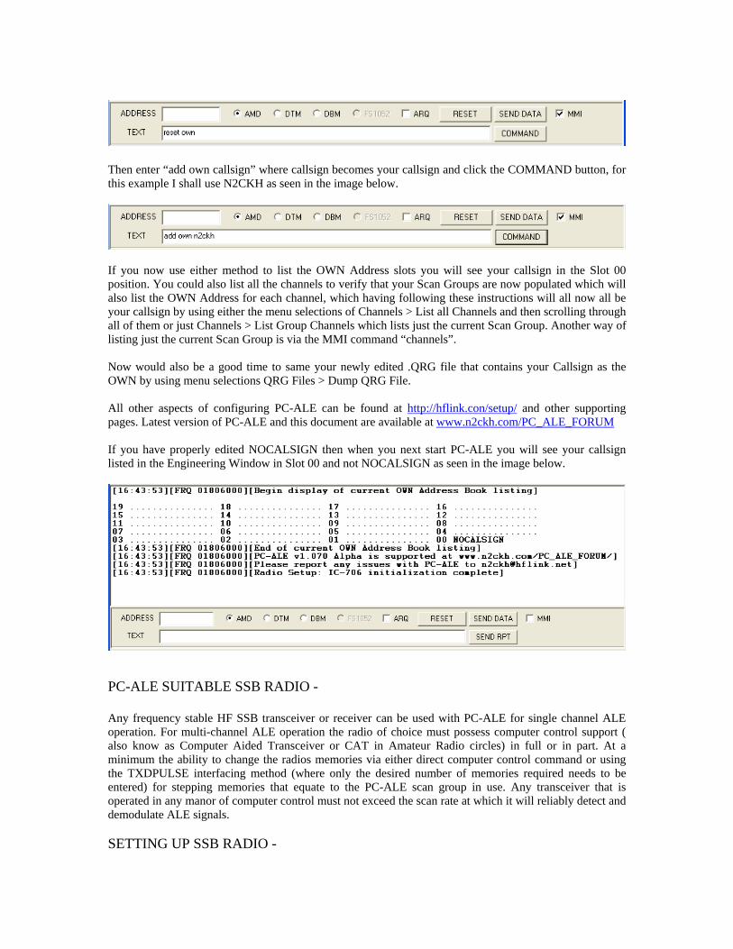
If you now use either method to list the OWN Address slots you will see your callsign in the Slot 00 position. You could also list all the channels to verify that your Scan Groups are now populated which will also list the OWN Address for each channel, which having following these instructions will all now all be your callsign by using either the menu selections of Channels > List all Channels and then scrolling through ll of them or just Channels > List Group Channels which lists just the current Scan Group. Another way of
.con/setup/
alisting just the current Scan Group is via the MMI command “channels”. Now would also be a good time to same your newly edited .QRG file that contains your Callsign as the OWN by using menu selections QRG Files > Dump QRG File. All other aspects of configuring PC-ALE can be found at http://hflink and other supporting
ages. Latest version of PC-ALE and this document are available at www.n2ckh.com/PC_ALE_FORUMp If you have properly edited NOCALSIGN then when you next start PC-ALE you will see your callsign
sted in the Engineering Window in Slot 00 and not NOCALSIGN as seen in the image below.
ncy stable HF SSB transceiver or receiver can be used with PC-ALE for single channel ALE peration. For multi-channel ALE operation the radio of choice must possess computer control support ( lso know as Computer Aided Transceiver or CAT in Amateur Radio circles) in full or in part. At a
mories via either direct computer control command or using nly the desired number of memories required needs to be
tered) for stepping memories that equate to the PC-ALE scan group in use. Any transceiver that is
li
PC-ALE SUITABLE SSB RADIO - Any frequeoaminimum the ability to change the radios methe TXDPULSE interfacing method (where oenoperated in any manor of computer control must not exceed the scan rate at which it will reliably detect and demodulate ALE signals. SETTING UP SSB RADIO -

The radio receiver section must provide for at least 2.0Khz IF SSB filtering where an IF Shift control provides for centering on the ALE 8FSK 1625hz signal center. With wider IF SSB filtering the centering on 1625hz becomes less and less critical, military radios for which ALE was developed typically use 2.8 to
.0Khz (300-3300hz centered on 1650hz) filters. The images below depict the TUNE Tones display and the e image depicts the IF SHIFT set too low for best ALE results, where
passband. Whereas in 2., the image depicts the IF SHIFT properly set
3affect of IF SHIFT settings. In 1., th
e IF Shift is center of the 2.4Khzthup for a 1625hz center passband.. The image in 3. depicts the IF shift to high, such as 1800-1900hz. As one can easily see, only the middle image comes close to providing the full BW needed for the 750-2500hz ALE tones as seen just listening to channel noise.
1. TOO LOW 2. CENTER 1625 3. TOO HIGH This issue of IF BW and Passband Centering really manifests itself on poor signals, such as weak or fading signals or under very poor channel conditions. In extensive testing with signals just barely above the noise floor, only a 30% success rate was achieved using th IF SHIFT center detent position as seen in 1. TOO LOW ab me IF SHIFT setting will reoptimal, e just ab the IF
HIFT setting resulting in 2. CENTER 1625 above achieves 90-100% success rate using just AMD, let
nded for feeding the PC-ALE modem.
r CAT control, only radios that are listed in
e ove, using that sa sult in 70-90% success rate if signal levels are
which is not usually th case. However, when the signals are ove the noise floorSalone DBM/DTMBRD or DBM/DTM ARQ message protocols. Without either 3Khz IF BW filters or proper IF SHIFT adjustment, the modem does not see the full spectrum of ALE waveform required and thus results will suffer. In addition the receiver section AGC must be set to FAST and such things as Notch Filtering and other types of DSP filtering should be disabled. Newer transceivers with receiver section dual frequency monitor, such as Dual Watch in many ICOM transceivers must also be disabled. In addition receiver RF gain and squelch if adjustable must be wide open. The use of fixed level receiver line audio over receiver speaker audio is highly recomme For transceivers, the RX/TX/RX turn-over timing of just about any make/model radio should be fast enough for ALE operation. However most HF transceivers make use of Power Amplifier (PA) spectral purity filters that are selected via relays based on frequency of operation, which during scanning are constantly switching and will if not placed into bypass prematurely shorten the relay life span.
or stations contemplating extended term ALE operations undeFthe radio type matrix as being rated QS/S (Quiet Scanning/Sounding) should be selected for use. Lastly the radio audio drive level should be adjusted so that the ALC reading just barely moves at any time during ALE 8FSK tones being sent.

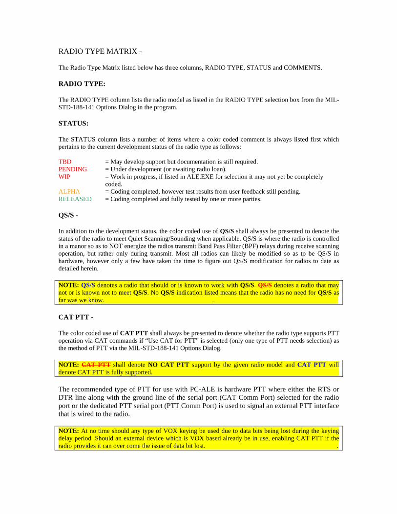
RADIO TYPE MATRIX - The Radio Type Matrix listed below has three columns, RADIO TYPE, STATUS and COMMENTS. RADIO TYPE: The RADIO TYPE column lists the radio model as listed in the RADIO TYPE selection box from the MIL-STD-188-141 Options Dialog in the program. STATUS: The STATUS column lists a number of items where a color coded comment is always listed first which pertains to the current development status of the radio type as follows: TBD = May develop support but documentation is still required. PENDING = Under development (or awaiting radio loan). WIP = Work in progress, if listed in ALE.EXE for selection it may not yet be completely
coded. ALPHA = Coding completed, however test results from user feedback still pending. RELEASED = Coding completed and fully tested by one or more parties. QS/S - In addition to the development status, the color coded use of QS/S shall always be presented to denote the status of the radio to meet Quiet Scanning/Sounding when applicable. QS/S is where the radio is controlled in a manor so as to NOT energize the radios transmit Band Pass Filter (BPF) relays during receive scanning operation, but rather only during transmit. Most all radios can likely be modified so as to be QS/S in hardware, however only a few have taken the time to figure out QS/S modification for radios to date as detailed herein. NOTE: QS/S denotes a radio that should or is known to work with QS/S. QS/S denotes a radio that may not or is known not to meet QS/S. No QS/S indication listed means that the radio has no need for QS/S as far was we know. . CAT PTT - The color coded use of CAT PTT shall always be presented to denote whether the radio type supports PTT operation via CAT commands if “Use CAT for PTT” is selected (only one type of PTT needs selection) as the method of PTT via the MIL-STD-188-141 Options Dialog. NOTE: CAT PTT shall denote NO CAT PTT support by the given radio model and CAT PTT will denote CAT PTT is fully supported. The recommended type of PTT for use with PC-ALE is hardware PTT where either the RTS or DTR line along with the ground line of the serial port (CAT Comm Port) selected for the radio port or the dedicated PTT serial port (PTT Comm Port) is used to signal an external PTT interface that is wired to the radio. NOTE: At no time should any type of VOX keying be used due to data bits being lost during the keying delay period. Should an external device which is VOX based already be in use, enabling CAT PTT if the radio provides it can over come the issue of data bit lost. .
To make use of the radio port DTR line for PTT, DTR can not be used for any other purpose, thus DTR for powering an external level converter and DTR for MUTE must not be checked. NOTE: If an external interface is wired to the DTR line and DTR for D.C. Power is checked, the DTR line will be held high, thus if that line is used for PTT the radio will always be keyed until either DTR for Power is unchecked or any jumpers of diodes in the interface are opened. . To make use of the radio port RTS line for PTT, if supported by the radio type being used, hardware handshaking can not be used as the RTS/CTS lines are already being used. NOTE: If an interface is already in use where RTS is normally used for PTT and DTR is used for D.C. Power, but it is desired to make use of hardware handshaking, should the interface have a VOX switch (such as older RigBlaster models) and the radio support CAT PTT, then placing the interface switch into VOX and selecting CAT PTT is an option that works. For external interfacing of PTT when CTS/RTS is being used for hardware handshaking, DTR for PTT can be used. However if DTR is required for Muting and a unit such as the RigBlaster is being used then alternative approach is to use CAT PTT and place the unit into VOX from Auto. CHAN - If the Radio Type selected supports the option of using radio memory channels or only supports the use of memory channels than CHAN shall be listed. NOTE: CHAN shall denote support for the given radio model for Radio Memory Channel based scanning which is ENABLED/DISABLED using the MMI commands ENABLE CHANNEL or DISABLE CHANNEL via the Data Bar when MMI is checked if the radio in question optionally supports this method. If CHAN is the only method the radio supports then CHAN ONLY will be listed, in which case the MMI commands have no effect.
The radio memory channels must be programmed to match the PC-ALE Scan Group channel numbers so that the listed channels that make up the scan group are properly selected in the radio.
CAT MUTE - If the Radio Type selected supports a CAT MUTE command or CAT Volume control then CAT MUTE shall be listed.
NOTE: CAT MUTE shall denote support for CAT MUTING where it must be enabled via the MIL-STD-188-141 Options Dialog along with the method being selected if the radio supports more than one method of muting. For CAT Volume Level Muting a MUTE and UN-MUTED level must be provided. .
When a radio does not support CAT muting at all, the only MUTE operation will be RTS/DTR for MUTING if enabled by “Use DRT for Mute” or “Use RTS for Mute”. CAT MUTING is optional for radio muting whereas a selection can be made between CAT vs. RTS/DTR for MUTING via a check box on the MIL-STD-188-141 options dialog. In addition, as a number of radios support both CAT Speaker Audio Level and a CAT MUTE command there is another check box is available to select the Level method when a radio supports both methods. CAT MUTING requires that line audio output from the radio be fed to the ALE modem and not speaker output. With RTS/DTR the speaker output can still be used as long as the pickup is on the swinger of the relay directly from the radios aux speaker port.

NOTE: For Kenwood radio type selection the RS-232 cabling and the signal lines must allow for the radio ID to be read from the radio to know that the Kenwood model being used supports CAT MUTING. . In support of CAT MUTING there are two speaker audio level entries on the MIL-STD-188-141 Options Dialog in support of the Speaker Level muting method. One is the UNMUTED level and the other being MUTED level. The MUTED audio is set to 0 as the default and UNMUTED to 25 by default. Either can be set to the range of 0..255 as some radios have the range of 0..100 and others 0..255 and others are in between. This allows for the MUTED level to be completely 0 or some lower level than the normal (UNMUTED) listening audio level. When the muting configuration selections have been made, clicking on the MUTE icon on the button bar will ENABLE or DISABLE muting and a message to that affect is now displayed in the Engineering Window. During scanning the audio will UNMUTE upon and ALE Link and again MUTE when the ALE Link is cleared automatically. When the program is terminated normally the radio will also UNMUTE. Otherwise the user needs to use the MUTE button to change the mute state. For those using receivers the MUTE button is the normal means to UMUTE unless your station is configured to intercept a muti-station call. CUSTOM RADIO PORT PARAMETERS (CPP) - On the MIL-STD-188-141 options menu next to the COM port entry (COM ports 1..16 are supported) for CAT control, is a button labeled “Radio 1 Comm Port”, this selects the Custom Port Parameters setup dialog.
NOTE: Along with the STATUS, CPP shall denote Custom Port Parameters are supported for changing the baud rate and perhaps other parameters for the given radio model and not fixed, where the default values are listed immediately after.
When not using the Custom Radio Port Setup (CRPS) interface, all radios are supported their highest baud rate setting or the default factory port parameters when only one baud rate is provided by the radio. The baud rate selected using CRPS must be 0 to make use of the PC-ALE default coding. A notable exception is Kenwood Amateur Grade transceivers where the Radio Type selections KENWOOD and KENWOOD_HS are both set to 4800 baud by default in PC-ALE due to years of radios only supporting such. It is always best to have your radio powered and attached to the proper serial port at program start and for some make/models such as Kenwood it is mandatory for reading the radio ID when the program starts. At present no radios support “Radio Address” via the CRPS interface. Should the user choose to use the Custom Port Parameter interface, they must be sure to configure the radio properly and enter the proper parameters as well as take into consideration that baud rate has an affect of ALE Channel Scan Rate support. The CPP serial port settings are only enabled when the baud rate is other than 0, which tells the tool not to use the hard coded parameters, when 0 (regardless of other entries on this dialog) the default coded parameters are used. CPP can be entered for only one instance of use, thus when CCP settings are changed for the currently selected radio type selected, if they do not apply to another radio type that may later be selected where said other radio type supports CPP settings, if the parameters selected do not apply, they would need to be updated.
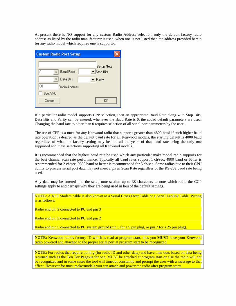
At present there is NO support for any custom Radio Address selection, only the default factory radio address as listed by the radio manufacturer is used, when one is not listed then the address provided herein for any radio model which requires one is supported.
If a particular radio model supports CPP selection, then an appropriate Baud Rate along with Stop Bits, Data Bits and Parity can be entered, whenever the Baud Rate is 0, the coded default parameters are used. Changing the baud rate to other than 0 requires selection of all serial port parameters by the user. The use of CPP is a must for any Kenwood radio that supports greater than 4800 baud if such higher baud rate operation is desired as the default baud rate for all Kenwood models, the starting default is 4800 baud regardless of what the factory setting may be due all the years of that baud rate being the only one supported and these selections supporting all Kenwood models. It is recommended that the highest baud rate be used which any particular make/model radio supports for the best channel scan rate performance. Typically all baud rates support 1 ch/sec, 4800 baud or better is recommended for 2 ch/sec, 9600 baud or better is recommended for 5 ch/sec. Some radios due to their CPU ability to process serial port data may not meet a given Scan Rate regardless of the RS-232 baud rate being used. Any data may be entered into the setup note section up to 38 characters to note which radio the CCP settings apply to and perhaps why they are being used in lieu of the default settings. NOTE: A Null Modem cable is also known as a Serial Cross Over Cable or a Serial Laplink Cable. Wiring is as follows: Radio end pin 2 connected to PC end pin 3 Radio end pin 3 connected to PC end pin 2 Radio end pin 5 connected to PC system ground (pin 5 for a 9 pin plug, or pin 7 for a 25 pin plug). NOTE: Kenwood radios factory ID which is read at program start, thus you MUST have your Kenwood radio powered and attached to the proper serial port at program start to be recognized NOTE: For radios that require polling (for radio ID and other data) and have time outs based on data being returned such as the Ten Tec Pegasus for one, MUST be attached at program start or else the radio will not be recognized and in some cases the tool will timeout constantly and prompt the user with a message to that affect. However for most make/models you can attach and power the radio after program starts
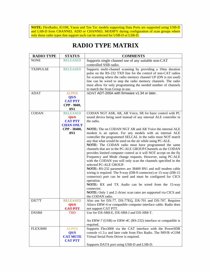
NOTE: FlexRadio, ICOM, Yaesu and Ten Tec models supporting Data Ports are supported using USB-D and LSB-D from CHANNEL ADD or CHANNEL MODIFY during configuration of scan groups where only those radio types that support such can be selected for USB-D or LSB-D.
RADIO TYPE MATRIX
RADIO TYPE STATUS COMMENTS NONE RELEASED Supports single channel use of any suitable non-CAT
controlled SSB radio. TXDPULSE RELEASED Supports multi-channel scanning by providing a 10ms duration
pulse on the RS-232 TXD line for the control of non-CAT radios for scanning where the radio memory channel UP (DN is not used) line can be wired to step the radio memory channels. The radio must allow for only programming the needed number of channels to match the Scan Group in use.
ADAT ALPHA QS/S
CAT PTT CPP - 9600,
8N1
ADAT ADT-200A with firmware v1.34 or later.
CODAN RELEASED QS/S
CAT PTT CHAN ONLY CPP - 38400,
8N1
CODAN NGT ASR, AR, AR Voice, SR for basic control with PC sound device being used instead of any internal ALE controller in the radio. NOTE: The on CODAN NGT AR and AR Voice the internal ALE modem is an option. For any models with an internal ALE controller the programmed SELCAL in the radio must NOT match any that what would be used on the air while using PC-ALE. NOTE: The CODAN radio must have programmed the same channels that are in the PC-ALE GROUP/Channels as the CODAN provides limited computer control as it will NOT accept on the fly Frequency and Mode change requests. However, using PC-ALE with the CODAN you will only scan the channels specified in the selected PC-ALE GROUP. NOTE: RS-232 parameters are 38400 8N1 and null modem cable wiring is required. The 9-way (DB-9 connector) or 15-way (DB-15 connector) port can be used and must be configured for CICS operation. NOTE: RX and TX Audio can be wired from the 15-way connector. NOTE: Only 1 and 2 ch/sec scan rates are supported via CICS and the CODAN radio.
DX77T RELEASED QS/S
CAT PTT
Also use for DX-77, DX-77EQ, DX-701 and DX-707. Requires Alinco ERW-4 or compatible computer interface cable. Radio does not support CAT PTT.
DXSR8 TBD Use for DX-SR8-E, DX-SR8-J and DX-SR8-T. An ERW-7 (USB) or ERW-4C (RS-232) interface or compatible is required.
FLEX3000 ALPHA QS/S
CAT MUTE CAT PTT
Supports Flex3000 via the CAT interface with the PowerSDR console v1.3.x and later code from Flex Radio. The N8VB vCOM Virtual Serial Ports Driver is required. Supports DATA port using USB-D and LSB-D.

Radio is pre-configured at program start for best settings for ALE operation as follows: TBD All commands to include the extended ZZxx commands from the CAT Command Dictionary dated February 2010 have been coded.
FLEX5000 ALPHA QS/S
CAT MUTE CAT PTT
Supports Flex-5000A, Flex-5000C (and possibly the Sunair RT-8100) via the CAT interface with the PowerSDR console v1.3.x and later code from Flex Radio. The N8VB vCOM Virtual Serial Ports Driver is required. Supports DATA port using USB-D and LSB-D. Radio is pre-configured at program start for best settings for ALE operation as follows: TBD All commands to include the extended ZZxx commands from the CAT Command Dictionary dated February 2010 have been coded. Will support FLEX-5000-ATU when CAT commands are added. NOTE: For Flex-3000 support the FLEX3000 selection must be used as the PA design uses relays.
FT450 RELEASED
QS/SCAT PTT
CAT MUTE CPP - 38400
Direct RS-232 without need of external level converter. The CAT timeout should be set to 3000ms. This model supports optional use of RTS/CTS, use FT450_HS selection. Support for USER_L and USER_U for the DATA port is made by selecting LSB-D and USB-D respectfully from Channel ADD/MODIFY. Do not use DIG_VOX operation for ALE. NOTE: FSK and FSK_R selections also support the DATA port whereas RTTY is the same as LSB.
FT450_HS RELEASED
QS/SCAT PTT
CAT MUTE
CPP – 38400
Same as FT450 above except support CTS/RTS operation.
FT600 RELEASED QS/S
CAT PTT
a.k.a. Vertex System 600
FT650 RELEASED QS/S
CAT PTT
Also FT-655. An external level converter using a 1/8 inch 3 conductor stereo plug where tip is Serial Data Out from the PC and shield is ground is required from the external level converter. The ring should only be connected if the RxD line will be monitor for Squelch status for scanning applications which PC-ALE does not support. This radio does NOT use any BPF relays.
FT757GX RELEASED CAT PTT
QS/S
Radio does not support CAT PTT
FT767 ALPHA Radio does not support CAT PTT

CAT PTT QS/S
FT817 RELEASED QS/S
CAT PTT CPP – 38400,
8N2
Also used for FT-817ND, FT-857x, FT-897x.
FT817DIG RELEASED QS/S
CPP – 38400, 8N2
As FT187 but supports DIG mode to use data port at rear of radio and the mode defined DIG, either LSB or USB but not both.
FT847 RELEASED QS/S
CAT PTT CPP – 57600,
8N2
NOTE: Requires the use of Null Modem cable. See the Yaesu section regarding interfacing to the radio otherwise. NOTE: Radio must be turned on before software is started else the radio will not respond commands.
FT890 RELEASED QS/S
CAT PTT
This choice supports the older FT-100, FT-747, FT-80C, FT-840, FT-890, FT-900, SB-1400. NOTE: Do not use this selection for the FT-990 as it does not support QS/S operation for that model radio, see the stand alone FT-990 selection. NOTE: An FT-890 QS/S hardware modification is available, refer to the MARS-ALE support files at: http://www.n2ckh.com/MARS_ALE_FORUM/hardwaremods.html
FT920 RELEASED QS/S
CAT PTT
CAT PTT is not listed in the manual. Coded as others in its class for CAT PTT, feedback from AAR3SJ is that it works. The FT-920 uses a straight RS-232 cable, no external level converter is required.
FT920DATA RELEASED QS/S
CAT PTT
See FT920 above as well. The DATA-LSB and DATA-USB modes are needed for use with the DATA port which in must be selected as LSB-D and USB-D using Channel ADD. However, be sure to set the AFSK-FSK switch to AFSK on the radio and setup the radio for the +2125hz offset in the U-45 setup menu as the software will subtract 2125hz from the assigned channel frequency so that the radio is on frequency, as the DATA port setup has NO provision for setting a 0hz offset. Also, the operator will need to manually switch from DATA to Voice in multimode operation, it recommended that the B VFO be used in conjunction with radio memory channels. The software is ALWAYS using A VFO. The operator will need to switch back to VFO A unless the Up/Down Channel or Scan is used. The mic jack is not active in data mode. Also, the operator will need to manually switch from DATA to Voice in multimode operation and use Channel UP/Down or Scan to go back to ALE data. The RX audio out on this port is a constant-level 100 mV rms @ 600ohm audio output line (as is the AF Jack) which is not affected by the position of the front-panel AF GAIN control. This output should be taken to your sound card Line-In. However, if the gain and range of adjustment is not sufficient, Mic-in may be tried.
FT950 RELEASED QS/S
CAT PTT
Direct RS-232 without need of external level converter. The CAT timeout should be set to 3000ms. This model supports optional use of RTS/CTS, use FT950_HS selection.

CAT MUTE CPP - 38400
Support for USER_L and USER_U for the DATA port is made by selecting LSB-D and USB-D respectfully from Channel ADD/MODIFY. Do not use DIG_VOX operation for ALE.
FT950_HS RELEASED QS/S
CAT PTT CAT MUTE CPP – 38400
Same as FT950 above except support CTS/RTS operation.
FT980 RELEASED CAT PTT
QS/S
Radio does not support CAT PTT
FT990 RELEASED QS/S
CAT PTT
This selection is specific to the FT-990 and QS/S operation. NOTE: FT-990 requires ROM version 1.2 or later.
FT1000MP RELEASED QS/S
CAT PTT
Use for all FT-1000 series radios. NOTE: FT-1000D requires ROM version 6.0 or later.
FT2000 RELEASED QS/S
CAT PTT CAT MUTE CPP – 38400,
8N2
Also for FT-2000D.
FT2000HS RELEASED QS/S
CAT PTT MUTE
CPP – 38400, 8N2
This selection uses the CTS/RTS handshaking. Also for FT-2000D.
FTdx5000 ALPHA QS/S
CAT PTT CAT MUTE CPP – 38400,
8N2
Use setup menu 104 to select the SSB-TX-BPF for either 200-2800hz, 300-2700hz or to 3000hz BW. Use setup menu 103 to select the SSB mic audio port, this is a poor design if it must be done all the time, most will likely want to use a RigBlaster type interface to the standard 8 pin mic port on the rear of the radio.
FTdx5000HS ALPHA QS/S
CAT PTT CAT MUTE CPP – 38400,
8N2
This selection uses the CTS/RTS handshaking.
FTdx9000 RELEASED QS/S
CAT PTT CAT MUTE CPP – 38400,
8N2
Use setup menu 70 to select the SSB-TX-BPF for either 300-2700hz or to 3000hz BW. Use setup menu 69 to select the SSB mic audio port, this is a poor design if it must be done all the time, most will likely want to use a RigBlaster type interface to the standard 8 pin mic port on the rear of the radio. NOTE: FTDX-9000 CAT support currently suffers a known bug that requires a 200ms pause before data write/reads of a new value which impedes smooth operation.
FURUNO TBD QS/S ? CHAN
Supports models FS-15xx: 1500, 1500P, 1501, 1502, 1503, 1503-EM, 1507, 1550, 1552, 1562, 1570, 2570, 5070 and perhaps other models using Furuno MIF protocol.

CAT PTT CAT MUTE CPP – 9600,
7E2
For ALE the default is 9600 baud, however some older radios may only support 4800 which the user will need to select in setup.
GENERIC ICOM RELEASED
CPP – User Entered
This selection does not support any particular model ICOM CI-V compatible radio. User must select correct radio address and RS-232 port parameters. It is always best to select an ICOM radio by its model number listed under “Radio Type” where each model has been coded with the factory default address and the highest baud rate the radio model supports as listed herein. Implements only basic radio features. CAT PTT is applied, but will only work if the physical radio supports CAT PTT. User must select for SPLIT VFO operation to bypass PA filter relays for QS/S operation if the radio benefits from such operation. NOTE: Does not support the use of IC-735 or IC-751 models. NOTE: Does not support the use of USB-D or USB-L. NOTE: Does not support ICOM Codec capable USB radio models.
IC78 RELEASED CAT PTT
QS/S CAT MUTE CPP – 19200,
8N1
Radio does not support CAT PTT. NOTE: See QS/S modification at: http://hflink.com/icom/ic718/
IC703 RELEASED QS/S
CAT MUTE CPP – 19200,
8N1
Can be interfaced for DATA port using USB-D and LSB-D.
IC706 RELEASED CAT PTT
QS/S CPP – 19200,
8N1
Radio does not support CAT PTT
IC706MkII RELEASED CAT PTT
QS/S CPP – 19200,
8N1
Radio does not support CAT PTT
IC706MkIIG RELEASED CAT PTT
QS/S CPP – 19200,
8N1
Radio does not support CAT PTT
IC707 RELEASED CAT PTT
QS/S
Radio does not support CAT PTT
IC-718 RELEASED CAT PTT
QS/S
Radio does not support CAT PTT. NOTE: See QS/S modification at: http://hflink.com/icom/ic718/

CAT MUTECPP – 19200,
8N1
IC725 RELEASED CAT PTT
QS/S CPP - 9600,
8N1
Radio does not support CAT PTT. NOTE: Factory addressing is used, WRT address diodes D57-D63, only D60 and D62 should be in place for the factory address of 28h. Diode D64 for transceive operation should no be installed either. NOTE: 9600 baud is being used, not the factory default 1200 baud. As such, the CI-V Baud Rate diode, D2 must be in place and D3 must be empty. Also diode D4, the factory default, must be in place for standard 5 byte frequency data.
IC726 RELEASED CAT PTT
QS/S CPP - 9600,
8N1
Radio does not support CAT PTT NOTE: Factory addressing is used, WRT address diodes D57-D63, only D61 and D62 should be in place for the factory address of 30h. Diode D64 for transceive operation should no be installed either. NOTE: 9600 baud is being used, not the factory default 1200 baud. As such, the CI-V Baud Rate diode, D2 must be in place and D3 must be empty. Also diode D4, the factory default, must be in place for standard 5 byte frequency data.
IC728 RELEASED QS/S
CAT PTT CPP - 9600,
8N1
Radio does not support CAT PTT. Also use for IC-77. NOTE: Factory addressing is used, WRT address diodes D57-D63, only D60, D61 and D62 should be in place for the factory address of 38h. Diode D64 for transceive operation should no be installed either. NOTE: 9600 baud is being used, not the factory default 1200 baud. As such, the CI-V Baud Rate diode, D2 must be in place and D3 must be empty. Also diode D4, the factory default, must be in place for standard 5 byte frequency data.
IC729 RELEASED CAT PTT
QS/S
CPP - 9600, 8N1
Radio does not support CAT PTT NOTE: Factory addressing is used, WRT address diodes D57-D63, only D58, D60, D61 and D62 should be in place for the factory address of 3Ah. Diode D64 for transceive operation should no be installed either. NOTE: 9600 baud is being used, not the factory default 1200 baud. As such, the CI-V Baud Rate diode, D2 must be in place and D3 must be empty. Also diode D4, the factory default, must be in place for standard 5 byte frequency data.
IC735 RELEASED CAT PTT
QS/S CPP - 9600,
8N1
Also supports IC-731 and IC-731S. Radio does not support CAT PTT. The IC-735 is factory set to 1200 baud. It is however recommended that the J22 settings be changed for 9600 baud operation where the first two position set the baud rate where 1 is

ON and 2 is OFF. To change the baud rate from 1200 to 9600 you need to remove the PA heat sink.
IC736 RELEASED CAT PTT
QS/S
Radio does not support CAT PTT
IC737 RELEASED CAT PTT
QS/S
Also use for IC-737A. Radio does not support CAT PTT.
IC738 RELEASED CAT PTT
QS/S
Radio does not support CAT PTT
IC746 RELEASED QS/S
CAT PTT CAT MUTE CPP – 19200,
8N1
IC746PRO RELEASED QS/S
CAT PTT CAT MUTE CPP – 19200,
8N1
Also use for IC-7400. Can be interfaced for DATA port using USB-D and LSB-D.
IC751 RELEASED CAT PTT
QS/S
Also use for IC-750 and IC-751A. Radio does not support CAT PTT NOTE: 9600 baud is being used, not the factory default 1200 baud. Set UX-14 S1-1 ON and S1-2 OFF for 9600 baud.
IC756 RELEASED QS/S
CAT PTT CPP - 19200,
8N1
IC756PRO RELEASED QS/S
CAT PTT CAT MUTE CPP – 19200,
8N1
Also use for Signal One Milspec 1030E-DSP. Can be interfaced for DATA port using USB-D and LSB-D.
IC756PROII RELEASED QS/S
CAT PTT CAT MUTE CPP – 19200,
8N1
Can be interfaced for DATA port using USB-D and LSB-D.
IC756PROIII RELEASED QS/S
CAT PTT CAT MUTE CPP – 19200,
8N1
Can be interfaced for DATA port using USB-D and LSB-D.
IC761 RELEASED CAT PTT
QS/S ?
Radio does not support CAT PTT. Also use for IC-760.
IC765 RELEASED Radio does not support CAT PTT

CAT PTT QS/S
IC775 RELEASED CAT PTT
QS/S
Radio does not support CAT PTT
IC781 RELEASED CAT PTT
QS/S
Radio does not support CAT PTT. Also use for IC-780 and Signal One Milspec 1030C
IC7000 RELEASED QS/S
CAT PTT CAT MUTE CPP – 19200,
8N1
IC7200 RELEASED QS/S
CAT PTT CAT MUTE CPP – 19200,
8N1
Can be interfaced for DATA port using USB-D and LSB-D. When the USB port is used the radio CODEC can be selected as the ALE modem instead of the PC Sound Device. NOTE: See QS/S modification at: http://hflink.com/icom/ic7200/ic7200_quiet_scan_mod2.jpg
IC7600 PENDING QS/S ?
CAT PTT CAT MUTE CPP – 19200,
8N1
Can be interfaced for DATA port using USB-D and LSB-D. When the USB port is used the radio CODEC can be selected as the ALE modem instead of the PC Sound Device,
IC7700 RELEASED QS/S
CAT PTT CAT MUTE CPP - 19200,
8N1
Can be interfaced for DATA port using USB-D and LSB-D.
IC7800 RELEASED QS/S
CAT PTT CAT MUTE CPP – 19200,
8N1
NOTE: QS/S capable WRT the BPF filters, but RF mixer filters are also relay switched, but do not present the problems associated with potential failure of TX BPF relays. Can be interfaced for DATA port using USB-D and LSB-D.
IC9100 TBD Awaiting docs. ICF7000 RELEASED
QS/S CAT PTT
CAT MUTE
ICOM internal ALE modem transceiver where the radio is NOT placed into “SELCALL SQUELCHED SCAN” and thus its internal ALE modem is not enabled. This selection is for stand alone operation using the PC sound device for all modem operation. See additional notes below for ICOM Marine Grade radios. NOTE: Radio address must be set to 9.
ICM700PRO RELEASED QS/S
CAT PTT CAT MUTE
See IC-M710 above below. NOTE: Radio address must be set to 2.
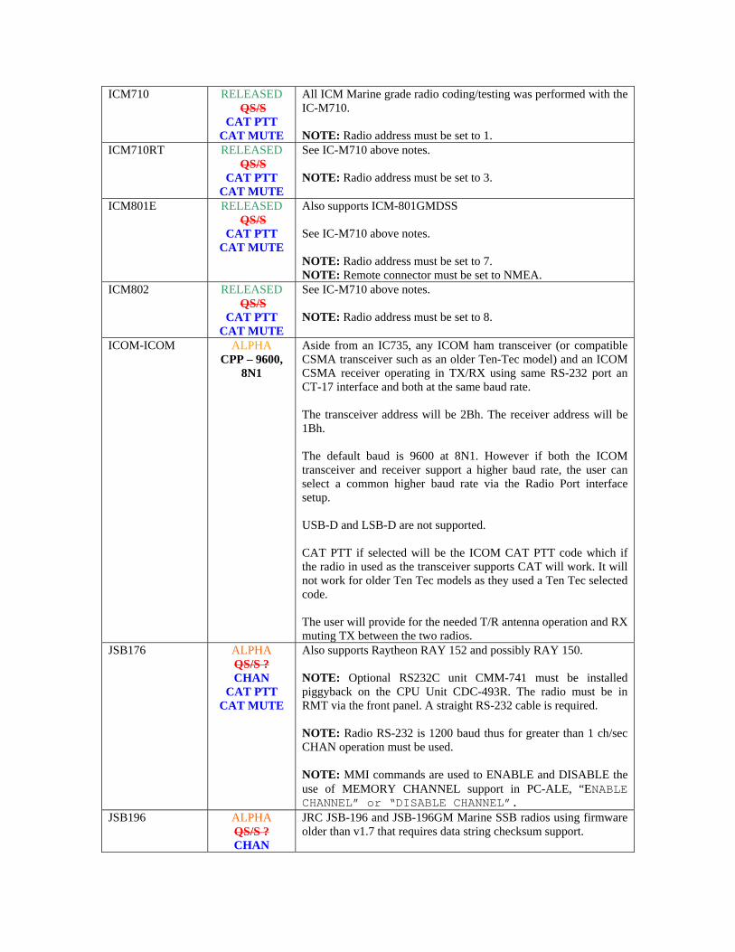
ICM710 RELEASED QS/S
CAT PTT CAT MUTE
All ICM Marine grade radio coding/testing was performed with the IC-M710. NOTE: Radio address must be set to 1.
ICM710RT RELEASED QS/S
CAT PTT CAT MUTE
See IC-M710 above notes. NOTE: Radio address must be set to 3.
ICM801E RELEASED QS/S
CAT PTT CAT MUTE
Also supports ICM-801GMDSS See IC-M710 above notes. NOTE: Radio address must be set to 7. NOTE: Remote connector must be set to NMEA.
ICM802 RELEASED QS/S
CAT PTT CAT MUTE
See IC-M710 above notes. NOTE: Radio address must be set to 8.
ICOM-ICOM ALPHA CPP – 9600,
8N1
Aside from an IC735, any ICOM ham transceiver (or compatible CSMA transceiver such as an older Ten-Tec model) and an ICOM CSMA receiver operating in TX/RX using same RS-232 port an CT-17 interface and both at the same baud rate. The transceiver address will be 2Bh. The receiver address will be 1Bh. The default baud is 9600 at 8N1. However if both the ICOM transceiver and receiver support a higher baud rate, the user can select a common higher baud rate via the Radio Port interface setup. USB-D and LSB-D are not supported. CAT PTT if selected will be the ICOM CAT PTT code which if the radio in used as the transceiver supports CAT will work. It will not work for older Ten Tec models as they used a Ten Tec selected code. The user will provide for the needed T/R antenna operation and RX muting TX between the two radios.
JSB176 ALPHA QS/S ? CHAN
CAT PTT CAT MUTE
Also supports Raytheon RAY 152 and possibly RAY 150. NOTE: Optional RS232C unit CMM-741 must be installed piggyback on the CPU Unit CDC-493R. The radio must be in RMT via the front panel. A straight RS-232 cable is required. NOTE: Radio RS-232 is 1200 baud thus for greater than 1 ch/sec CHAN operation must be used. NOTE: MMI commands are used to ENABLE and DISABLE the use of MEMORY CHANNEL support in PC-ALE, “ENABLE CHANNEL” or “DISABLE CHANNEL”.
JSB196 ALPHA QS/S ? CHAN
JRC JSB-196 and JSB-196GM Marine SSB radios using firmware older than v1.7 that requires data string checksum support.

CAT PTT CAT MUTE
NOTE: MMI commands are used to ENABLE and DISABLE the use of MEMORY CHANNEL support in PC-ALE, “ENABLE CHANNEL” or “DISABLE CHANNEL”. NOTE: Null modem cable required.
JSB196GM ALPHA QS/S ? CHAN
CAT PTT CAT MUTE
JRC JSB-196 and JSB-196GM Marine SSB radios using firmware v1.7 or newer that does not require data string checksum support. NOTE: MMI commands are used to ENABLE and DISABLE the use of MEMORY CHANNEL support in PC-ALE, “ENABLE CHANNEL” or “DISABLE CHANNEL”. NOTE: Null modem cable required.
JST245 RELEASED QS/S
CAT MUTE
Also select for JST-145 and JST-135 operation. NOTE: For JST-135 1200 baud must be selected.
K2/100 RELEASED
QS/S ?
Use “KENWOOD” selection, K2/100 emulates a Kenwood TS-570SD. Under no circumstances should you use a standard RS232 cable to connect your K2 to a computer, you MUST use the cable specified by Elecraft in the KIO2 or KPA100 manual to avoid damage to your rig and/or computer. For more information see K/100 notes.
K3 PENDING CPP – 38400,
8N1
CAT control follows that of the K2 at this time. The K3 uses a standard RS232 cable. The use of RTS and DTR via radio configuration can be made for PTT support.
K505DSP RELEASED QS/S
CAT MUTE
Kachina 505DSP and also for KC105CTX. This radio is fully under computer control, as is the Ten-Tec Pegasus TT550, both designed by the same engineer. Polling is required to keep radio port open. Operates at 9600 baud. See detailed Kachina 505DSP notes in the body of the RHUG.
KENWOOD
RELEASED QS/S
CAT MUTE For models:
TS480, TS570, TS590, TS870 and TS2000
Supports all Kenwood HF CAT controlled radios. The radio model ID is read at program start and parameters are reset for best ALE operation. Any future radios with an unknown radio ID will be treated as a TS-590. 4800 baud 8N2 operation is default if the CPP is not used to select a higher baud rate. The TS-480, TS-570, TS-870, TS-2000 and TS-590 series must be reset to 4800 baud N82. e.g. the factory default setting is 9600 baud on the TS-2000 set menu 56 to 4800 baud. TS-590 can be CAT controlled via USB as well. It is questionable at this time based on the docs as to how well the TS-590 will work via USB for both CAT control and PC Sound Device modem support at the same time. ANI ACC Port/USB Port PTT: CAT PTT is supported for the TS-480 and TS-590 other than the MIC port by selection of USB-D or LSB-D when Adding/Editing channels. NOTE: Kenwood recommends that Hardware Handshaking be used to avoid loss of data to the radio, this is especially important at the higher baud rates for communications and the higher ALE Scan Rates. See KENWOOD_HS below.
KENWOOD_HS RELEASED The _HS appended designates support of RTS/CTS hardware

QS/S
CAT MUTE For models:
TS480, TS570, TS590, TS870 and TS2000
handshaking. Otherwise see KENWOOD above for more details. NOTE: For external interfacing PTT only DTR can be used when handshaking is used as RTS is used for handshaking. For a unit such as the RigBlaster, an alternative approach is to use CAT PTT and place the unit into VOX from Auto.
MICOM RELEASED
9600, 8O1 QS/S
CAT PTT CHAN
CAT MUTE
Supports Mobat Missle Command (MICOM) models MICOM-1, 2E, 2B, 2BF, 2BT, 2EF, 2ES, 2ET-RDP, 2ET-RDP2, 2MF, 2R, 2RS, 2TS, RM125, RM125,R, RM500, RM500E, RM500R, RM1000, 3F, 3R, 3T, RDP3-DHS, MICOM-H and perhaps others. Set the radio for 9600 baud operation. Either the MIC or AUX port of the radio using TXD, RXD and GND will work. Refer to your radios manual. Interfacing to the PC is standard RS-232 levels with straight wiring. If using the rear J3 Accessory connector the RX and TX audio lines are differential and must be wired using 600 or 1,000 ohm isolation transformers. Ready to go J3 cables complete with RS-232 DTR line opto isolated PTT are available from Bill Holland, KC2CNB, (http://hollandelectronics.net/ or 1-609-693-7281) at a reasonable cost. Just tell him it’s for MARS-ALE and if you want a DB9 or DB25 on the PC side and the cable length you require between the PC and radio. NOTE: The SELCAL being used for the OWN in the software MUST not match any SELCAL programmed into the radio if an ALE modem/controller is installed in the radio else the radio will clear the ALE link established. NOTE: CAT PTT can be used when interface via either the MIC port or rear J3 Accessory port. NOTE: MICOM DSP SQ can be used during ALE ops. NOTE: CAT MUTE levels can be entered from 0..255 CAT MUTING speaker level is supported and for the Unmuted level setting if CAT MUTE level is used, a value of 16 seems to be a good listening level if using external speaker P/N HSN4027A. When using an internal speaker the volume levels need to be much higher, especially on MICOM 2 models. NOTE: MICOM 2x models must be in CHAN mode for both discrete frequency/mode or CHAN mode operation. For MICOM 3 radios it does not matter if the radio is in CHAN or FREQ mode. NOTE: MMI commands are used to ENABLE and DISABLE the use of MEMORY CHANNEL support in MARS-ALE, “ENABLE CHANNEL” or “DISABLE CHANNEL” which is retained by the ALE.DAT file. The radio memory channels must match the .QRG file channels, e.g. channels 1 thru 10. NOTE: When using the Manual Radio Control Panel AM selects

AME and FM selects PLT (PILOT). Also, all tuning steps for UP/DOWN work, but the use of 1Hz will not be seen on the radio display until its used 10 times for a 10Hz change. RX frequency coverage is 100Khz to 30Mhz. NOTE: The MICOM-2BF, MICOM-2MF and MICOM-H Amateur Radio band version and perhaps others require the FLN2423 RS-232 option installed for computer control via J3, however the MIC port TXD, RXD, GND lines can be used for CAT control without the FLN2423.
PT8000A TBD
QS/S ?
Hilderbling PT8000A, PT8000B, PT8000C in 2010? NOTE: Awaiting documentation. Known to follow ICOM CI-V CSMA protocol at this time only.
RF350ALK RELEASED QS/S
CAT PTT CAT MUTE
CHAN CPP - 9600,
7O1
Uses an ASCII protocol that supports the Harris RF-350, RF-350K, RT-1446 URC, AN/URC-119, AN/URC-121(V) basic control with PC sound device for MIL-STD-188-141A ALE, 188-141B AQC-ALE and all ALE and MIL-STD-188-110x all data modes. When radio is placed into remote, no local control is available. The J9 REMOTE connection is used for PC sound device modem and TNC connections. The radio’s inputs are differential, but care must be taken to observe polarity of the audio lines for connection to the computer sound card. Phone operation is via the radio MIC in connection with the RED PTT button. See RF350ALK_TNC for auxiliary interfacing. Supports remote control board number 10088-6000. Part number is located in the upper left corner of the board which is installed behind the display board. This is the standard, non-addressable board and is used with the RF-352 remote control and the RF-7210A adaptive controller. Radios with this card are usually marked with a tag beside the unit identifier stating “THIS UNIT HAS BEEN MODIFIED USING KIT 10191-40029. SEE THE RF-7100-04 MANUAL FOR DETAILS.” RS-232 Interface: Radio Remote Control Interface (A1A19, Located behind display panel, p/n 10088-6000) Set S-1 to position 9 (ADAPT) Set S-2 to Position 1 (RS-232) [To use with Harris RF-7210 Adaptive controller, S-2 should be set to position 2 (RS-422.)] Set S-5 to 4 wire audio input/output. The software is operating at 9600 Baud, 7-bit data, odd parity, 1 stop bit, no handshake. NOTE: Radio firmware should be at least Rev Level 604. Rev 601 may work, but Radio must be in USB mode before starting. A firmware upgrade may be required to support ADAPT, please contact AFA1PU for further details at: [email protected] Cable Wiring: Computer 9-pin D Radio 25-pin D 2 (input) 3 (output) 3 (output) 2 (input)
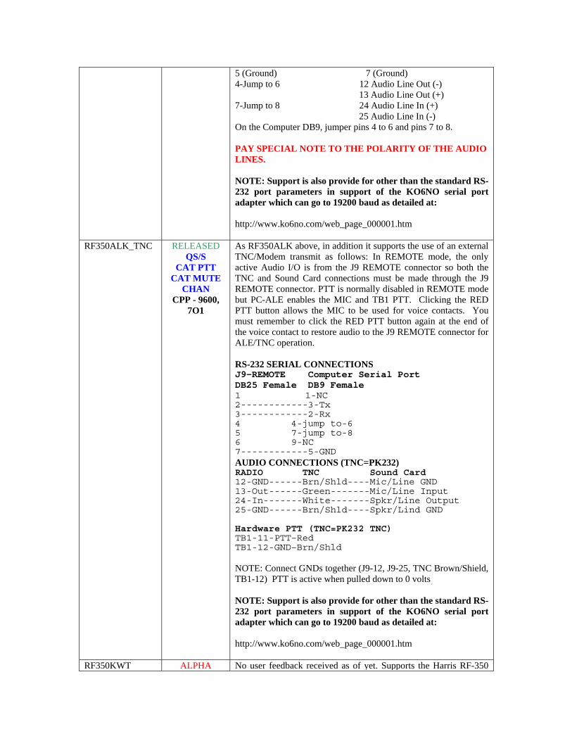
5 (Ground) 7 (Ground) 4-Jump to 6 12 Audio Line Out (-) 13 Audio Line Out (+) 7-Jump to 8 24 Audio Line In (+) 25 Audio Line In (-) On the Computer DB9, jumper pins 4 to 6 and pins 7 to 8. PAY SPECIAL NOTE TO THE POLARITY OF THE AUDIO LINES. NOTE: Support is also provide for other than the standard RS-232 port parameters in support of the KO6NO serial port adapter which can go to 19200 baud as detailed at: http://www.ko6no.com/web_page_000001.htm
RF350ALK_TNC RELEASED QS/S
CAT PTT CAT MUTE
CHAN CPP - 9600,
7O1
As RF350ALK above, in addition it supports the use of an external TNC/Modem transmit as follows: In REMOTE mode, the only active Audio I/O is from the J9 REMOTE connector so both the TNC and Sound Card connections must be made through the J9 REMOTE connector. PTT is normally disabled in REMOTE mode but PC-ALE enables the MIC and TB1 PTT. Clicking the RED PTT button allows the MIC to be used for voice contacts. You must remember to click the RED PTT button again at the end of the voice contact to restore audio to the J9 REMOTE connector for ALE/TNC operation. RS-232 SERIAL CONNECTIONS J9-REMOTE Computer Serial Port DB25 Female DB9 Female 1 1-NC
2------------3-Tx
3------------2-Rx
4 4-jump to-6
5 7-jump to-8
6 9-NC
7------------5-GND
AUDIO CONNECTIONS (TNC=PK232) RADIO TNC Sound Card 12-GND------Brn/Shld----Mic/Line GND 13-Out------Green-------Mic/Line Input 24-In-------White-------Spkr/Line Output 25-GND------Brn/Shld----Spkr/Lind GND Hardware PTT (TNC=PK232 TNC) TB1-11-PTT–Red TB1-12-GND–Brn/Shld NOTE: Connect GNDs together (J9-12, J9-25, TNC Brown/Shield, TB1-12) PTT is active when pulled down to 0 volts. NOTE: Support is also provide for other than the standard RS-232 port parameters in support of the KO6NO serial port adapter which can go to 19200 baud as detailed at: http://www.ko6no.com/web_page_000001.htm
RF350KWT ALPHA No user feedback received as of yet. Supports the Harris RF-350
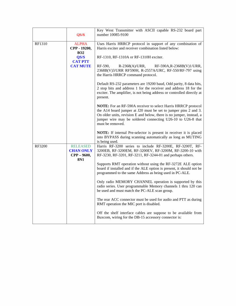
QS/S
Key West Transmitter with ASCII capable RS-232 board part number 10085-9100
RF1310 ALPHA CPP - 19200,
8O2 QS/S
CAT PTT CAT MUTE
Uses Harris HRRCP protocol in support of any combination of Harris exciter and receiver combination listed below: RF-1310, RF-1310A or RF-1310H exciter. RF-590, R-2368(A)/URR, RF-590A,R-2368B(V)1/URR, 2368B(V)3/URR RF590H, R-2557A/URC, RF-550/RF-797 using the Harris HRRCP command protocol. Default RS-232 parameters are 19200 baud, Odd parity, 8 data bits, 2 stop bits and address 1 for the receiver and address 18 for the exciter. The amplifier, is not being address or controlled directly at present. NOTE: For an RF-590A receiver to select Harris HRRCP protocol the A14 board jumper at J20 must be set to jumper pins 2 and 3. On older units, revision E and below, there is no jumper, instead, a jumper wire may be soldered connecting U26-10 to U26-8 that must be removed. NOTE: If internal Pre-selector is present in receiver it is placed into BYPASS during scanning automatically as long as MUTING is being used.
RF3200 RELEASED CHAN ONLY CPP – 9600,
8N1
Harris RF-3200 series to include RF-3200E, RF-3200T, RF-3200EB, RF-3200EM, RF-3200EV, RF-3200M, RF-3200-10 with RF-3230, RF-3201, RF-3211, RF-3244-01 and perhaps others. Supports RMT operation without using the RF-3272E ALE option board if installed and if the ALE option is present, it should not be programmed to the same Address as being used in PC-ALE. Only radio MEMORY CHANNEL operation is supported by this radio series. User programmable Memory channels 1 thru 120 can be used and must match the PC-ALE scan group. The rear ACC connector must be used for audio and PTT as during RMT operation the MIC port is disabled. Off the shelf interface cables are suppose to be available from Buxcom, wiring for the DB-15 accessory connector is:
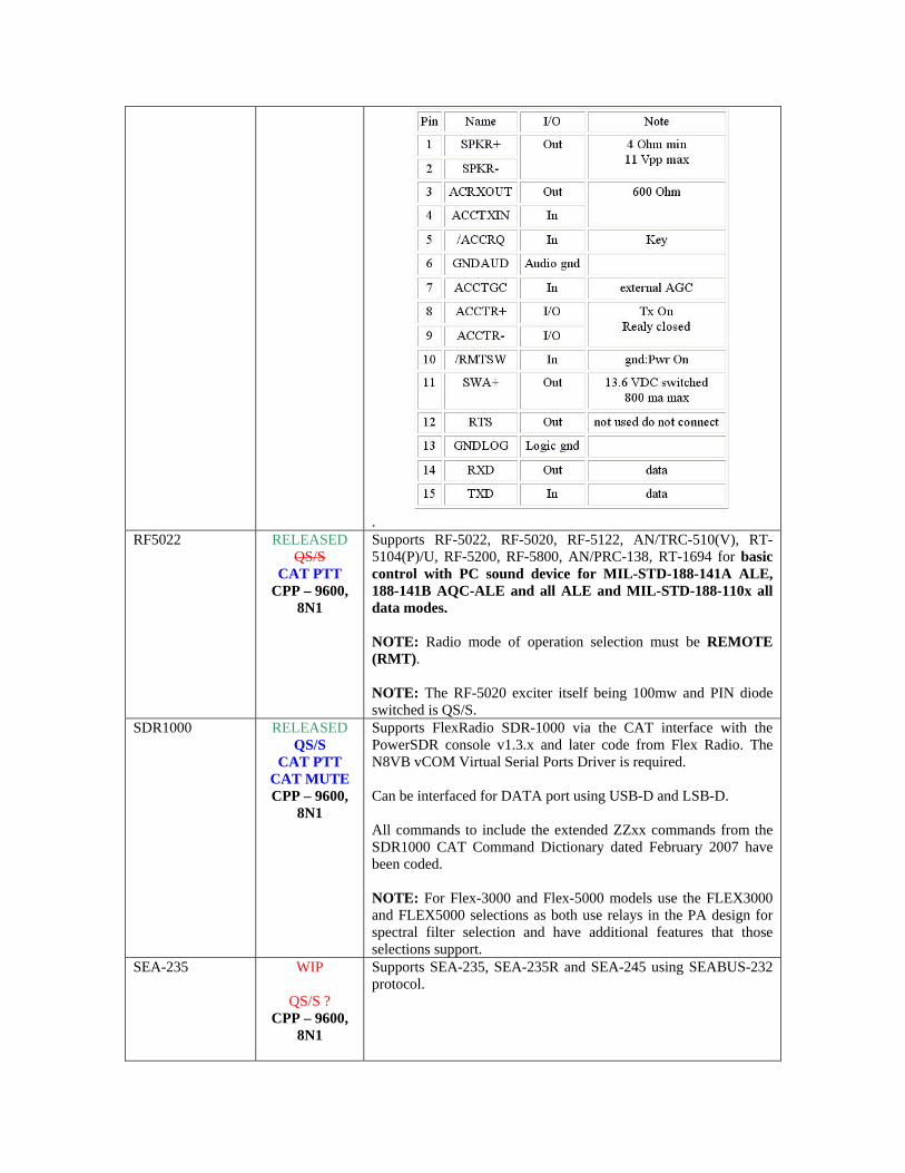
.
RF5022 RELEASED QS/S
CAT PTT CPP – 9600,
8N1
Supports RF-5022, RF-5020, RF-5122, AN/TRC-510(V), RT-5104(P)/U, RF-5200, RF-5800, AN/PRC-138, RT-1694 for basic control with PC sound device for MIL-STD-188-141A ALE, 188-141B AQC-ALE and all ALE and MIL-STD-188-110x all data modes. NOTE: Radio mode of operation selection must be REMOTE (RMT). NOTE: The RF-5020 exciter itself being 100mw and PIN diode switched is QS/S.
SDR1000
RELEASED QS/S
CAT PTT CAT MUTE CPP – 9600,
8N1
Supports FlexRadio SDR-1000 via the CAT interface with the PowerSDR console v1.3.x and later code from Flex Radio. The N8VB vCOM Virtual Serial Ports Driver is required. Can be interfaced for DATA port using USB-D and LSB-D. All commands to include the extended ZZxx commands from the SDR1000 CAT Command Dictionary dated February 2007 have been coded. NOTE: For Flex-3000 and Flex-5000 models use the FLEX3000 and FLEX5000 selections as both use relays in the PA design for spectral filter selection and have additional features that those selections support.
SEA-235 WIP
QS/S ? CPP – 9600,
8N1
Supports SEA-235, SEA-235R and SEA-245 using SEABUS-232 protocol.
SEA-330 PENDING
QS/S ?
Supports SEA-330. NOTE: Requires SEA2320 interface to allow PC connection to the radio. The SEA2320 converts RS232 to RS485 type protocol that the radio uses.
SGC2000 RELEASED QS/S
CHAN
Also use for PRC-2250MIL. Can make use of straight RS-232 or Null Modem cable when internal jumper is properly set. From the factory, the radio is configured for a straight cable. Only Pins 1, 2 and 3 should be wired in the RS-232 cable. Direct control and radio memory channel control of the SGC is provided. If memory channels are used, the radios first 100 user channels need to be configured to match the scan group channels 1..100 NOTE: MMI commands are used to ENABLE and DISABLE the use of MEMORY CHANNEL support in PC-ALE, “ENABLE CHANNEL” or “DISABLE CHANNEL”. NOTE: Due to the nature of Windows OS interrupts and the required RS232 ATTENTION timing, the radio may not always respond to a command string from software. This is more likely to occur at the 5 ch/sec scan rate if the OS busy servicing other programs. The only way to completely over come this is either to use an external hardware ALE modem/controller with these radios, such as the Frederick/NSG M1045 or M2045 or for a hardware microcontroller based interfacing controller to be designed for interface use, such as something based on a PIC processor that performs the RS232 ATTENTION when data is sent.
T4150 ALPHA QS/S
CAT PTT MUTE
CPP – 19200, 8N1
Supports Cubic T4150 or T4180 exciter (at radio address 100) mated to a Cubic Cubic CDR-32xx and LCR/SMR-20xx family receiver (at radio address 001) and PA400 amplifier (at radio address 123). Fo is sent to PA400 then Exciter before TX. CAT PTT is sent to PA400 then Exciter before TX if CAT PTT is selected , regardless if exciter and PA400 are wired for direct PTT. At program start RF power level 1 for 100w operation is sent to PA400, if another PAxxxx model is in use then power output potential will be greater. HEXRADCMD in CONFIG.DAT can be used to select a higher power level if desired. All units on RS-232 bus must be set to the same port parameters. Proper RS-232 multi-drop or RS-422 interface must be used. Optionally an RS-232 to IEEE-488 converter can be used.
T4180 ALPHA QS/S
CAT PTT MUTE
CPP – 19200, 8N1
Supports Cubic T4150 or T4180 exciter (at radio address 100) mated to a Cubic Cubic CDR-32xx and LCR/SMR-20xx family receiver (at radio address 001) and PA5050A or other amplifier (at radio address 123). All units on RS-232 bus must be set to the same port parameters. Proper RS-232 multi-drop or RS-422 interface must be used.
Optionally an RS-232 to IEEE-488 converter can be used. NOTE: Items 1..3 below only apply if PA5050A is not cabled and configured for direct control by the exciter 1. Fo is sent to PA5050A then Exciter before TX. 2. CAT PTT is sent to PA45050A then Exciter before TX if CAT PTT is selected , regardless if exciter and PA400 are wired for direct PTT. 3. At program start RF power level 1 for 100w operation is sent to PA5050A. HEXRADCMD in CONFIG.DAT can be used to select a higher power level if desired.
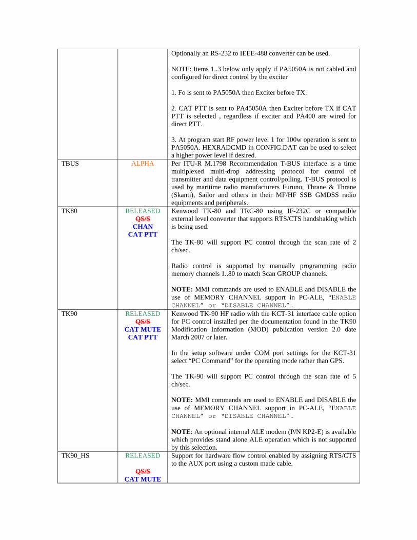
TBUS ALPHA Per ITU-R M.1798 Recommendation T-BUS interface is a time multiplexed multi-drop addressing protocol for control of transmitter and data equipment control/polling. T-BUS protocol is used by maritime radio manufacturers Furuno, Thrane & Thrane (Skanti), Sailor and others in their MF/HF SSB GMDSS radio equipments and peripherals.
TK80 RELEASED QS/S
CHAN CAT PTT
Kenwood TK-80 and TRC-80 using IF-232C or compatible external level converter that supports RTS/CTS handshaking which is being used. The TK-80 will support PC control through the scan rate of 2 ch/sec. Radio control is supported by manually programming radio memory channels 1..80 to match Scan GROUP channels. NOTE: MMI commands are used to ENABLE and DISABLE the use of MEMORY CHANNEL support in PC-ALE, “ENABLE CHANNEL” or “DISABLE CHANNEL”.
TK90 RELEASED QS/S
CAT MUTE CAT PTT
Kenwood TK-90 HF radio with the KCT-31 interface cable option for PC control installed per the documentation found in the TK90 Modification Information (MOD) publication version 2.0 date March 2007 or later. In the setup software under COM port settings for the KCT-31 select “PC Command” for the operating mode rather than GPS. The TK-90 will support PC control through the scan rate of 5 ch/sec. NOTE: MMI commands are used to ENABLE and DISABLE the use of MEMORY CHANNEL support in PC-ALE, “ENABLE CHANNEL” or “DISABLE CHANNEL”. NOTE: An optional internal ALE modem (P/N KP2-E) is available which provides stand alone ALE operation which is not supported by this selection.
TK90_HS RELEASED
QS/S CAT MUTE
Support for hardware flow control enabled by assigning RTS/CTS to the AUX port using a custom made cable.

CAT PTT TRP8250 RELEASED
QS/S ? CAT MUTE
Skanti TRP-8250 Serial communications is 2400 7O1 via the Telex port.
TRP9000 TBD Skanti TRP-9xxx NMEA protocol. T-BUS protocol is also supported by the TRP-9xxx series.
TT516 RELEASED QS/S
CAT PTT CHAN ONLY
Supports Argonaut V . The radios memory channels are used in sync with the .QRG file and can be programmed by PC-ALE directly. NOTE: This model Ten Tec uses diode switching thus no special programming is needed, no BPF relays to contend with.
TT538 RELEASED QS/S
CAT PTT CAT MUTE
Supports Ten Tec Jupiter. Do NOT use for OMNI VII TT588 in RADIO MODE as the TT588 has many differences. The TT538 Jupiter native command set requires at a minimum firmware version “1.18 05/12/02” or later in a Jupiter radio as it was at that point that the non-Pegasus PC control interface was added. However, as many bugs have been addressed in the radio with updates thereafter, some of which address the new command set, it is recommended that firmware version “1.28 03/01/06” or later be used. For anyone using firmware version “1.17” or older, you will need to select either TT550 or TT550MA as appropriate. TT538 uses MIC port for both voice and for ALE (on the Jupiter setup menu on the radio, for “Audio Source”, you select “MIC”). With a suitable interface such as a RigBlaster needs to used. PTT can only be DTR as RTS can NOT be used as the radio uses handshaking with the RTS/CTS lines and the Jupiter command set Radio does not support CAT PTT. NOTE: The tool writes the ALE RX channel to VFO A and the ALE TX channel to VFO B all the time as the Jupiter command set dictates that you must write to both VFO A and B. However, the Jupiter command set provides no command to place the radio into SPLIT operation, this must be done manually if the operator desires separate RX/TX frequency operation, otherwise the RX/TX channel will be the RX channel. NOTE: The TT538 can emulate the Pegasus transceiver, however its use precludes front panel operation while using the CAT interface. When uses with the TT550 or TT550MA selections, the Jupiter screen with change to the Pegasus flying horse logo when the radio is addressed with frequency and mode data for the first time. All radios parameters from the front panel will be locked out. There is a volume slider control on the Radio Control panel for adjusting receiver audio in Pegasus mode. NOTE: The Jupiter command set does not allow for selection between the mic port and rear auxiliary port for which the TT550 selection must be used.
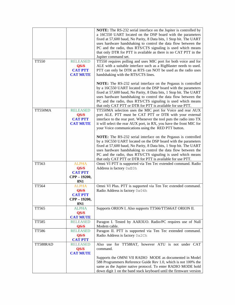
NOTE: The RS-232 serial interface on the Jupiter is controlled by a 16C550 UART located on the DSP board with the parameters fixed at 57,600 baud, No Parity, 8 Data bits, 1 Stop bit. The UART uses hardware handshaking to control the data flow between the PC and the radio, thus RTS/CTS signaling is used which means that only DTR for PTT is available as there is no CAT PTT in the Jupiter command set.
TT550 RELEASED QS/S
CAT PTT CAT MUTE
TT550 requires polling and uses MIC port for both voice and for ALE with a suitable interface such as a RigBlaster needs to used. PTT can only be DTR as RTS can NOT be used as the radio uses handshaking with the RTS/CTS lines. NOTE: The RS-232 serial interface on the Pegasus is controlled by a 16C550 UART located on the DSP board with the parameters fixed at 57,600 baud, No Parity, 8 Data bits, 1 Stop bit. The UART uses hardware handshaking to control the data flow between the PC and the radio, thus RTS/CTS signaling is used which means that only CAT PTT or DTR for PTT is available for use PTT.
TT550MA RELEASED QS/S
CAT PTT CAT MUTE
TT550MA selection uses the MIC port for Voice and rear AUX port ALE. PTT must be CAT PTT or DTR with your external interface to the rear port. Whenever the tool puts the radio into TX it will select the rear AUX port, in RX, you have the front MIC for your Voice communications using the RED PTT button. NOTE: The RS-232 serial interface on the Pegasus is controlled by a 16C550 UART located on the DSP board with the parameters fixed at 57,600 baud, No Parity, 8 Data bits, 1 Stop bit. The UART uses hardware handshaking to control the data flow between the PC and the radio, thus RTS/CTS signaling is used which means that only CAT PTT or DTR for PTT is available for use PTT.
TT563 ALPHA QS/S
CAT PTT CPP – 19200,
8N1
Omni VI PTT is supported via Ten Tec extended command. Radio Address is factory 0xE0h
TT564 ALPHA QS/S
CAT PTT CPP – 19200,
8N1
Omni VI Plus. PTT is supported via Ten Tec extended command. Radio Address is factory 0x04h
TT565 ALPHA QS/S
CAT MUTE
Supports ORION I. Also supports TT566/TT566AT ORION II.
TT585 RELEASED QS/S
Paragon I. Tested by AAR3UO. Radio/PC requires use of Null Modem cable.
TT586 RELEASED QS/S
CAT PTT
Paragon II. PTT is supported via Ten Tec extended command. Radio Address is factory 0x2Ch
TT588RAD RELEASED QS/S
CAT MUTE
Also use for TT588AT, however ATU is not under CAT command. Supports the OMNI VII RADIO MODE as documented in Model 588 Programmers Reference Guide Rev 1.0, which is not 100% the same as the Jupiter native protocol. To enter RADIO MODE hold down digit 1 on the band stack keyboard until the firmware version

string and RADIO appears on the display. TT588REM RELEASED
QS/S CAT PTT
CAT MUTE
For use for OMNI VII TT588 and TT588AT in REMOTE MODE, a new protocol that places the TT588 series radio into a hands off operation by the user. Can be interfaced for LINE port audio source using USB-D and LSB-D mode selections. When this is the case, the front MIC port for Voice communications is selected when using the RED PTT button. OMNI VII REMOTE MODE as documented in Model 588 Programmers Reference Guide Rev 1.0. To enter REMOTE MODE hold down digit 2 on the band stack keyboard until the firmware version string and REMOTE appears on the display.
TT599 TBD Also use for TT599AT. VX1400 TBD May work with VX1700 selections as coded when ALE-2 board is
not installed or if installed, not activate. NOTE: CT-62 via ATU port may work. If not the optional CT-139 cable which is required for external Modem, GPS and CW operation may be required.
VX1700 RELEASED QS/S
CAT PTT
Supports VX-1700 and VH-1700HF. If an optional ALE (P/N ALE-1) option board is installed, the ALE-1 if installed must NOT be enabled for PC-ALE use. RS-232 control can be had by either:
1. Using a CT-62 or compatible interface attached to the ATU TUNER port.
2. Using the 9-pin D GPS connector with a null modem
cable. To use this approach a one time procedure must be followed where switches S4002 and S4003 are placed into position A on the ALE-1 board assembly.
NOTE: Scan rates of 1, 2, 5 are supported with PC-ALE. All frequency control is on the fly with PC-ALE from .QRG file groups. NOTE: When using PC-ALE the radio is not QS/S as it is when using the ALE-1 option for control as not means of relay bypass is provided.
VX1700J2B RELEASED QS/S
CAT PTT
Same as VX1700 above but supports use of the data port where in the CE-77 software USB or LSB is selected as the J2B mode.
WJCSMA-ICOM ALPHA CPP – 9600,
8N1
An ICOM ham transceiver and Watkins-Johnson CSMA receiver in TX/RX using the same RS-232 port and CT-17 compatible interface. The ICOM transceiver needs to be set to radio address 28h W-J switches in A2S1 are used to enable either the RS-232C or the CSMA interface. Setting switch 4 of A2S1 to OFF (up) enables the RS-232C interface and setting switch 4 to ON enables the CSMA interface.
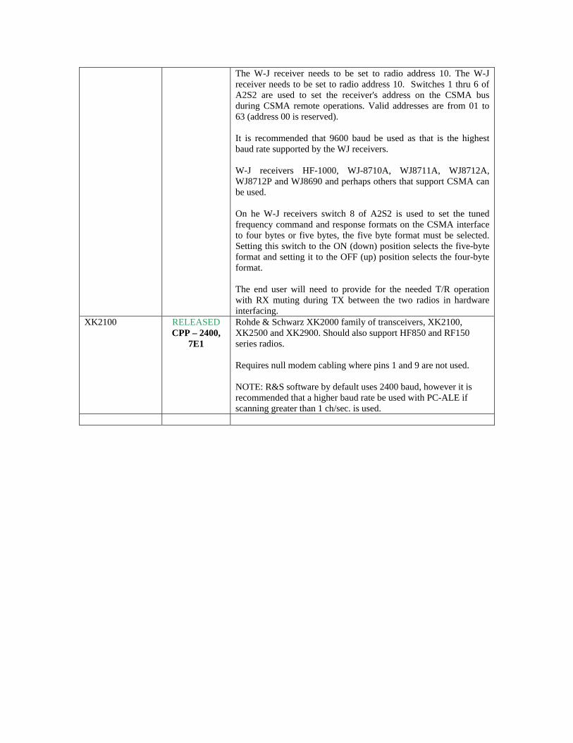
The W-J receiver needs to be set to radio address 10. The W-J receiver needs to be set to radio address 10. Switches 1 thru 6 of A2S2 are used to set the receiver's address on the CSMA bus during CSMA remote operations. Valid addresses are from 01 to 63 (address 00 is reserved). It is recommended that 9600 baud be used as that is the highest baud rate supported by the WJ receivers. W-J receivers HF-1000, WJ-8710A, WJ8711A, WJ8712A, WJ8712P and WJ8690 and perhaps others that support CSMA can be used. On he W-J receivers switch 8 of A2S2 is used to set the tuned frequency command and response formats on the CSMA interface to four bytes or five bytes, the five byte format must be selected. Setting this switch to the ON (down) position selects the five-byte format and setting it to the OFF (up) position selects the four-byte format. The end user will need to provide for the needed T/R operation with RX muting during TX between the two radios in hardware interfacing.
XK2100 RELEASED CPP – 2400,
7E1
Rohde & Schwarz XK2000 family of transceivers, XK2100, XK2500 and XK2900. Should also support HF850 and RF150 series radios. Requires null modem cabling where pins 1 and 9 are not used. NOTE: R&S software by default uses 2400 baud, however it is recommended that a higher baud rate be used with PC-ALE if scanning greater than 1 ch/sec. is used.

The current status for radio Receiver support is presented here: NOTE: All receivers that support CAT MUTING require manual un-mute. RADIO MODEL STATUS COMMENTS 95S-1 TBD Use for Collins 95S-1, 95S-1(A) AR-ALPHA TBD ARONE PENDING
CPP – 9600, 8N2 For AR-ONE, AR-ONE/BB. Default RS-232 port settings are 19200,N,8,2 with Xon/Xoff
AR5000 RELEASED CPP – 19200, 8N2
Use for AOR AR5000. Default RS-232 port settings are 19200,N,8,2 with Xon/Xoff
AR7000 RELEASED CPP – 19200, 8N2
Use for AOR AR7000. Default RS-232 port settings are 19200,N,8,2 with Xon/Xoff
AR7030 RELEASED Use for AOR AR7030 AR7070 TBD AR8600 ALPHA
CPP – 19200, 8N2 Use for AOR AR8600 and AR8600MkII. Default RS-232 port settings are 19200,N,8,2 with Xon/Xoff
DR333 TBD Mckay-Dymek DR333, DR3360 and DR300PCB. EK890 RELEASED
Use for Rhode & Schwarz EK095, EK890, EK891, EK893 RS-232 port set to 9600,E,7,1 by default.
EK896 RELEASED CPP – 19200, 8N1
Use for Rhode & Schwarz EK895 and EK896 RS-232 port set to 19200,N,8,1 by default.
EK2000 RELEASED CAT MUTE
CPP – 9600, 7E1
Use for Rhode & Schwarz EK2000 where address is set to 00 for single receiver operation.
EKD500 TBD Translating docs from German to English FRG100 RELEASED Use for Yaesu FRG-100 FRG8800 RELEASED Use for Yaesu FRG-8800 HF1000 RELEASED Use for Watkins-Johnson HF-1000, HF-1000A HF2050 RELEASED
CPP – 19200, 8N1
Use for Collins HF-2050, HF2050BRD and perhaps others. HF-2050 Remote control interface is RS-422 via DB25 female on rear of receiver for remote control using EIA Standard RS-422 wiring. An RS-422 to RS-232 converter is needed. Units with the pre-selector provide an RS-232 interface option for which a standard RS-232 cable is used.
HF150 PENDING Lowe HF-150. The IF-150 RS-232 interface cable is required. 1200 baud 8N1. FREQ/MODE and MEMORY supported via RS-232.
HF235 PENDING Lowe HF-235 and HF-235/F. The HF-235/RC RS-232 option is required 1200 8N1. Radio must be set to address 1. RTS/CTS required.
HF250 PENDING Lowe HF-250 KENWOOD or KENWOOD_HS
RELEASED Use for Kenwood R-5000
LCR2000 RELEASED
CPP – 19200, 8N1
Use for Cubic LCR-1200, LCR-2000, LCR-2400, SMR-2000, SMR-2400, CDR-3250, CDR-3280. Radio Address is fixed at 001 and default port parameters are 19200 8N1.
MICOM-1 Receiver WIP See the radio type selection MICOM above. NOTE: Requires FLN-5062A RS232 interface card.
NRD345 RELEASED Use for JRC NRD-345. Requires null modem cabling. NRD525 RELEASED Use for JRC NRD-525. Requires null modem cabling. NRD535 RELEASED Use for JRC NRD-535. Requires null modem cabling.

NRD535D RELEASED Use for JRC NRD-535D. Requires null modem cabling. NRD545 RELEASED
CAT MUTE Use for JRC NRD-545. . Requires null modem cabling. NOTE: The NRD-545 allows you to disable the band pass filters when scanning to disable the relays, unfortunately it can’t be done over the remote interface.
NRD630 TBD Documentation still required. PCR1000 RELEASED
CAT MUTE Use for ICOM PCR1000. Radio is used at default 9600 baud. The ICOM OPC-743 or any standard straight RS-232 cable will work.
PERSEUS For PERSEUS SDR receivers select Radio Type “Generic Icom” then click the Radio Port button and enter baud rate parameters and leave radio address as 00.
PRC1500 RELEASED CAT MUTE
Supports USB/VCP RS-232 based PCR1500, IC-R1500 and IC-R2500. NOTE: At this time, after the tool is started, if the MIL-STD-188-141 dialog is used to change and settings, clicking OK, will reset the radio and shut it down. A restart of the program will be required to reboot the radio Comm.. Port. Connection.
RA6790GM RELEASED CPP – 19200, 8N1
Use for RACAL RA6790GM, R-2174(A)/URR. May work for other RACAL receivers such as the RA6793A, R-2320/URR series, if so a report would be welcome, if not, inform us what RACAL supported is needed and provide the needed commands if possible. Computer control of the RA6790GM requires installation of the optional A6A1 Microprocessor Board. Should this be missing from your unit, Toronto Surplus (and likely others) have been known to have complete A6A1 and blank A6A1 boards, for more information see: http://www.torontosurplus.com For RS-232 operation soldered jumpers need to be in place on the A6A1 Microprocessor Board as follows: Link1 Install, Link2 Open, Link3 Install, Link4 Install, Link5 Install, Link6 Open. The receiver to PC RS-232 cable, it must be wired for Receiver Address 10, 19200 baud, No Parity, 1 Stop Bit. The cable connector on the A6A1 board on this receiver is a military type plug which can be acquired surplus from William Perry Co., Inc., 702 (Rear) Beechwood Road, Louisville KY 40207, 1-502-893-8724. A pre-wired cable can be purchased from Bill Holland, KC2CNB, http://hollandelectronics.net/, 1-609-693-7281 at a reasonable cost. Just tell him it’s for PC-ALE, if you want a DB9 or DB25 on the PC side and the length you require, 6 foot is standard.
RA6830JD ALPHA CPP – 19200, 8N1
Also for TCI-4070. RS-232 parameters of: 19200 baud, 8 data bits, No Parity, 1 Stop bit, Receiver Address 85. The receiver must have a (standard 25 pin DIN connector on rear for J-13, otherwise you have a GPIB-488 interface or none installed. NOTE: If you have a GPIB-488 interface, an RS-232 to

GPIB-448 converter such as the National Instruments GPIB-232-CV-A will be required, see http://www.ni.com/pdf/products/us/4gpib688-690.pdf NOTE: Receiver RS-232 serial port parameters are 19200 8N1 which are S1 switch selected as 1,2 and 3 OPEN for 19200, 4 OPEN for 1 stop bit, 5 DONT CARE, 6 CLOSED for NO PARITY, 7 and 8 CLOSED for 8 data bits. The mother board soldered Links in radio for RS-232 operation are: LINK2, LINK4, LINK7.
R8 RELEASED Use for Drake R8 R8A RELEASED Use for Drake R8A R8B RELEASED Use for Drake R8B R10 ALPHA
CPP – 19200, 8N ICOM R10
R20 ALPHA CPP – 19200, 8N
ICOM R20
R71 RELEASED Use for ICOM R71, R71A, R71D and R71E. NOTE: 9600 baud is being used, not the factory default 1200 baud. Set UX-14 S1-1 ON and S1-2 OFF for 9600 baud.
R72 RELEASED Use for ICOM R72. R75 RELEASED
CAT MUTE CPP – 19200, 8N1
Use for ICOM R75.
R3030STXx RELEASED CPP – 19200, 8N1
Use for Cubic models R-3030, R-3050, R-3080, R-3090, R-2307/U,R3030A NOTE: Three choices are available as R3030STX1, R3030STX2 and R3030STX3 for the required number of start characters to be sent. The Radio Address is fixed 01 and default port parameters are 19200 8N1.
R2411/U ALPHA
CPP – 19200, 8N1
Use for Cubic R-2411/U dual receiver. The receiver selected must be set to address 01 and be in REMOTE.
R5000 where KENWOOD is selected
RELEASED
Use for Kenwood R5000.
R7000 RELEASED CPP – 19200, 8N1
Use for Icom R7000
R7100 RELEASED CPP – 19200, 8N1
Use for Icom R7100
R8500 RELEASED CAT MUTE
CPP – 19200, 8N1
Use for Icom R8500
R9000 RELEASED CPP – 19200, 8N1
Use for Icom R9000
R9500 RELEASED CAT MUTE
CPP – 19200, 8N1
Use for Icom R9500
RF590 RELEASED CPP - 19200, 8O2
Use for RF-590, R-2368(A)/URR, RF-590A,R-2368B(V)1/URR, 2368B(V)3/URR RF590H, R-2557A/URC, RF-550/RF-797 using the Harris HRRCP command protocol.

RS-232 parameters are 19200 baud, Odd parity, 8 data bit, 2 stop bits and radio address 1. For the RF-590A, to select Harris HRRCP protocol the A14 board jumper at J20 must be set to jumper pins 2 and 3. On older units, revision E and below, there is no jumper, instead, a jumper wire may be soldered connecting U26-10 to U26-8 that must be removed.
RF-590A RELEASED CPP - 19200, 7O1
Use for RF-590A, RF590H, R-2368B(V)1/URR, 2368B(V)3/URR, R-2557A/URC with firmware 208C or above configured to use the ASCII command protocol. User must manually enable the front panel remote switch. Software is written for 19200 baud, Odd parity, 7 data bits and 1 stop bit using radio address 1 operation. For the RF-590A and later units of revision F and above, to select Harris ASCII protocol the A14 board jumper at J20 must be set to jumper pins 1 and 2. On older units, revision E and below, there is no jumper, instead, a jumper wire must be soldered connecting U26-10 to U26-8 for the ASCII protocol. WRT relay chatter, as here is no ASCII command take the top cover off, remove the A19 cover and pull the A19A2 daughter board. Use a thin wire and jumper the two coaxial connectors. Does not effect the BITE and the relays are pulled from the circuit. Submitted by AFA1PU.
RX320 RELEASED CAT MUTE
Use for Ten Tec RX320 series and the RX-321 models built for Globe Wireless.
RX330 RELEASED CPP - 9600, 8N1
Use for Ten Tec RX-330 Set parameters to radio address 1 and default 9600 baud with 8N1.
RX331 RELEASED CPP - 9600, 8N1
Use for Ten Tec RX-331 Set parameters to radio address 1 and default 9600 baud with 8N1.
RX340 RELEASED CPP - 9600, 8N1
Use for Ten Tec RX-340. Set parameters to radio address 1 and default 9600 baud with 8N1.
RX350 RELEASED CAT MUTE
Use for Ten Tec RX-350. Will also control TT538 Jupiter.
TCI8174 RELEASED CAT MUTE
CPP - 19200, 8N1
Use for TCI 8074, 8172, 8173, 8174 and perhaps other models. Radio Address 1 (ASCII letter A) where dip switch settings for S1 are 11100000 (1 is up 0 is down) . NOTE: For TCI-4070 see RA6830JD.
VR5000 RELEASED CPP - 57600,
8N1
Yaesu VR-5000. Requires a null modem cable.
WJ8711 RELEASED Use for Watkins-Johnson WJ-8711 and other WJ receivers. WJ8711A PENDING Use for Watkins-Johnson WJ-8711A and other WJ receivers. WJCSMA RELEASED Use for older Watkins-Johnson receivers via the CSMA port
(such as HF-1000, WJ-8710A, WJ8711A, WJ8712A, WJ8712P and possibly others) with an ICOM CT-17 or compatible interface with the receiver set to address 10. NOTE: Switches in A2S1 are used to enable either the RS-232C or the CSMA interface. Setting switch 4 of A2S1 to OFF (up) enables the RS-232C interface and setting switch 4 to ON enables the CSMA interface.

NOTE: Switch 8 of A2S2 is used to set the tuned frequency command and response formats on the CSMA interface to four bytes or five bytes, the five byte format must be selected. Setting this switch to the ON (down) position selects the five-byte format and setting it to the OFF (up) position selects the four-byte format.

WHAT TO DO WHEN YOUR RADIO TYPE IS NOT LISTED? If your CAT controllable radio is not listed by its model number under the RADIO TYPE column in the above chart, check to see if its listed in the COMMENTS column as being in the same family as the one listed. For example, under FT890 there are a number of Yaseu models as well as OEM models sold under other brand names that are all supported by the FT890 selection. If your radio is not listed under COMMENTS then follow the following advice per manufacturer radio type. ICOM: Dual Watch needs to be set to OFF for all models which provide the feature. The CI-V Transceive feature most be set to OFF for all models. ICOM radio models that support it should never be operated in AUTO BAUD, but rather setup for the highest baud rate that they support, which is 19200 for most recent models. Many older models can be changed to support 9600 by diode selection and must be reconfigured as such for ALE operation. Most recent ICOM models and some older high end models are QS/S compliant as detailed in the chart above under STATUS. If your model is not listed due to it being a brand new model not yet added, determine if its QS/S by changing bands from 160-10m with the radio in SPLIT VFO and if you hear no relays cycling you can assume the radio is QS/S. Then select the most recent ICOM model that is QS/S and change your radio address to the factory address for that model (see the list below), select the highest baud rate supported for that model and see if the radio functions properly. If the radio is not QS/S follow the steps as just detailed however select the most recent ICOM radio type that is no QS/S. All ICOM radio models listed under RADIO TYPE are supported using the default factory address and the highest baud rate supported. Select your specific model listed in the “Radio Type” pull down menu. Transceivers: IC7800: 6A IC781: 26 IC775: 46 IC765: 2C IC761: 1E IC756PROIII: 6E IC756PROII: 64 IC756PRO: 5C IC756: 50 IC751: 1C IC746PRO: 66 IC746: 56 IC738: 44 IC737: 3C IC736: 40 IC735: 04 IC729: 3A IC728: 38 IC726: 30 IC725: 28 IC718: 5E IC707: 3E IC706MkIIG: 58 IC706MkII: 4E IC706: 48 IC703: 68 IC78: 62 IC7000: 70 IC7200: 76 IC7600: 7A IC7700: 74 IC9100H: xx Receivers: ICR9000: 2A ICR7100: 34 ICR7000: 08 ICR8500: 4A ICR9500: 72 ICR75: 5A ICR71: 1A ICR72: 32

PCR-1000: N/A PCR-1500: N/A PCR-2500: N/A ICR10: 52 ICR20: 6C
KENWOOD All models are support by reading the Radio ID back at program start, which means the radio must be properly cabled to the PC for RS-232 control and turned on before starting the software. If the Radio ID is properly returned, but is not recognized in the database, its assumed to be a NEW model Kenwood radio and treated as if it is compatible with the full TS-480 series command set. If the radio ID type is NOT returned, the radio will be treated as a basic Kenwood model for frequency, mode and CAT PTT only. Both the KENWOOD and KENWOOD_HS selections support all models at 4800 baud 8N2 by default. For other RS-232 port parameters the custom port setup must be utilized to select the parameters that the radio is configured. All Kenwood models to date, except the TS-440 (which is excluded from QS/S SPLIT VFO operation) are QS/S compliant. Kenwood radios can be selected for use with and without hardware handshaking, for hardware handshaking, use KENWOOD_HS ( only CAT PTT or DTR PTT can be _HS as the RTS line is used in hand shaking). YAESU YAESU model sub family groupings at exist for a number of models, for example: FT817/FT817DIG - Select this choice for FT-817, FT-817ND, FT-857 and FT-897 models. FT890 - Select this choice for FT-100, FT-100D, FT-747GX, FT-840, FT-890, FT-900, FT-990 and also for the Heathkit SB-1400 (a.k.a. FT-747GX). FT1000MP - Select this choice for FT-1000, FT-1000D, FT-1000MP series. Ten Tec: Select from the specific models listed or the ICOM interface for older models as specified in your user manual. Although the OMNI VI and VI+ emulate the IC-735 and the Paragon II emulates the IC-765, they have been specifically coded for their factory addresses and to take advantage of extended CAT features such at CAT PTT operation.


![[XLS] · Web view005B PC Memory - 4MB 005C PC Memory - 6MB 005D PC Memory - 8MB 005E PC Memory - 10MB 005F PC Memory - 12MB 005G PC Memory - 14MB 005H PC Memory - 16MB 005I PC Memory](https://static.fdocuments.us/doc/165x107/5ab13df97f8b9ac66c8c4031/xls-view005b-pc-memory-4mb-005c-pc-memory-6mb-005d-pc-memory-8mb-005e-pc.jpg)


![REVISION BB QTH-XXX-XX-X-D-XXX - RS Componentsdocs-asia.electrocomponents.com/webdocs/115b/0900766b8115bb1b.pdf.xxxx: .0020[.051] material:.5mm double row hs terminal assembly by:](https://static.fdocuments.us/doc/165x107/5ab543387f8b9ab7638c8920/revision-bb-qth-xxx-xx-x-d-xxx-rs-componentsdocs-asia-0020051-material5mm.jpg)