Draft for comment I.S. 820:2009 - NSAI - NSAI · PDF fileB.2 Natural gas supply systems ......
84
Draft for comment I.S. 820:2009 Non-domestic gas installations (Edition 2) Enquiry period: 2009-08-17 to 2009-10-19 Readers are warned that this draft is subject to ongoing development and change As part of the NSAI Strategy 2009 – 2011 an informative Environmental Annex will be added before publication Please send your comments on the I.S. 820 comments sheet available on www.NSAI.ie to [email protected] or Gas Standards NSAI 1 Swift Square, Northwood, Santry Dublin 9
Transcript of Draft for comment I.S. 820:2009 - NSAI - NSAI · PDF fileB.2 Natural gas supply systems ......

Draft for comment
I.S. 820:2009
Non-domestic gas installations (Edition 2)
Enquiry period: 2009-08-17 to 2009-10-19
Readers are warned that this draft is subject to ongoing development and change
As part of the NSAI Strategy 2009 – 2011 an informative
Environmental Annex will be added before publication
Please send your comments on the I.S. 820 comments sheet available on www.NSAI.ie
to [email protected] or
Gas Standards NSAI 1 Swift Square, Northwood, Santry Dublin 9

REVISION
No. 1 : 2009
OF
Draft STANDARD SPECIFICATION ( Non-domestic gas installations (Edition 2))
Draft IRISH STANDARD 820 : 2009
____________________________
SCHEDULE
The standard has been revised in line with the relevant European Standards.

Document type: Document subtype: Document stage: CEN Enquiry Document language: E H:\GTSC\TC 02\I.S. 820\Edition 2 - 20__\I.S. 820_Ed2_ Draft 11.doc STD Version 2.2
/TC 2 GTSC Date: 2009-07
pr I.S. 820:2009
/TC 2 GTSC
Secretariat: NSAI
I.S. 820 — Non-domestic Gas Installations — (Edition 2)
Public comment draft
NOTE: This is a draft standard for public enquiry and comment only.
This is NOT a published Irish Standard
ICS:
Descriptors:
PUBLIC C
OMMENT DRAFT

pr I.S. 820:2009 (E)
2
Contents Page
Foreword..............................................................................................................................................................5 1 Scope ......................................................................................................................................................7 2 References..............................................................................................................................................7 3 Definitions ..............................................................................................................................................9 4 Design .................................................................................................................................................. 18 4.1 General................................................................................................................................................. 18 4.2 Design for protection in case of fire ................................................................................................. 19 4.3 Material selection................................................................................................................................ 19 4.4 Pipework installation design ............................................................................................................. 20 4.4.1 Sizing ................................................................................................................................................... 20 4.4.2 Location ............................................................................................................................................... 21 4.4.3 Safety devices..................................................................................................................................... 21 4.5 Declaration .......................................................................................................................................... 22 5 Construction........................................................................................................................................ 22 5.1 Installation ........................................................................................................................................... 22 5.2 Materials and jointing methods......................................................................................................... 22 5.2.1 General................................................................................................................................................. 22 5.2.2 Welded, brazed, soldered and fusion joints .................................................................................... 23 5.2.3 Mechanical joints................................................................................................................................ 23 5.2.4 Mechanical joints, threaded............................................................................................................... 23 5.2.5 Pressed joints ..................................................................................................................................... 24 5.2.6 Corrugated Stainless Steel Tubing (CSST)...................................................................................... 24 5.3 Resistance to fire................................................................................................................................ 24 5.4 Provisions for pipework..................................................................................................................... 25 5.4.1 Corrosion protection .......................................................................................................................... 25 5.4.2 Equipotential bonding........................................................................................................................ 25 5.4.3 External pipework............................................................................................................................... 25 5.5 Internal buried pipework .................................................................................................................... 26 5.6 Internal concealed pipework ............................................................................................................. 27 5.6.1 General................................................................................................................................................. 27 5.6.2 Pipework passing through external walls, cavity walls, solid floors or solid ceilings................ 27 5.6.3 Pipework in voids ............................................................................................................................... 27 5.7 Pipework in service shafts................................................................................................................. 27 5.8 Pipework in stairways ........................................................................................................................ 28 5.9 Pipework in lift shafts......................................................................................................................... 28 5.10 Indoor LPG pipework below ground level (e.g. Basements).......................................................... 28 5.11 Means of isolation............................................................................................................................... 28 5.12 Flexible appliance connectors .......................................................................................................... 29 5.13 Regulators and meters....................................................................................................................... 29 6 Testing of pipework............................................................................................................................ 29 6.1 Safety ................................................................................................................................................... 29 6.2 Strength and soundness test ............................................................................................................ 30 6.2.1 General................................................................................................................................................. 30 6.2.2 Test equipment ................................................................................................................................... 30 6.2.3 Test fluids ............................................................................................................................................ 30 6.2.4 Stabilisation......................................................................................................................................... 30 6.2.5 Test pressure ...................................................................................................................................... 31 6.2.6 Test duration ....................................................................................................................................... 31 6.2.7 Verification .......................................................................................................................................... 31
PUBLIC C
OMMENT DRAFT

pr I.S. 820:2009 (E)
3
7 Pipework commissioning ...................................................................................................................32 7.1 General .................................................................................................................................................32 7.2 Fitness test...........................................................................................................................................32 8 Admission of gas.................................................................................................................................32 8.1 General .................................................................................................................................................32 8.2 Purging .................................................................................................................................................33 8.3 Admission of gas (appliances) ..........................................................................................................33 9 Declaration of conformance...............................................................................................................33 9.1 General .................................................................................................................................................33 9.2 Installation declaration .......................................................................................................................33 9.2.1 General .................................................................................................................................................33 9.2.2 General information ............................................................................................................................34 9.2.3 Design...................................................................................................................................................34 9.2.4 Construction and testing....................................................................................................................34 9.2.5 Commissioning....................................................................................................................................34 9.2.6 Additional information required.........................................................................................................35 9.3 Appliance declaration .........................................................................................................................35 9.3.1 General .................................................................................................................................................35 9.3.2 Appliance declaration, additional information .................................................................................36 10 Use and maintenance..........................................................................................................................36 10.1 General recommendations .................................................................................................................36 10.2 Maintenance.........................................................................................................................................36 10.3 Gas releases ........................................................................................................................................37 10.4 Leak detection .....................................................................................................................................37 10.5 Operating pipework.............................................................................................................................37 10.6 Purging of fuel gas ..............................................................................................................................38 10.7 Re-admission of fuel gas to an existing installation .......................................................................38 11 Appliances ...........................................................................................................................................39 11.1 General .................................................................................................................................................39 11.2 The Appliance ......................................................................................................................................39 11.3 Appliances in educational establishments.......................................................................................39 11.4 Appliance location...............................................................................................................................39 11.5 Combustion products dispersal/flueing ...........................................................................................40 11.6 Provision of air ....................................................................................................................................40 11.7 Appliance commissioning..................................................................................................................41 11.7.1 General .................................................................................................................................................41 11.7.2 Minimum requirements of commissioning an appliance ................................................................41 Annex A (informative) Gas characteristics.....................................................................................................42 A.1 Characteristics.....................................................................................................................................42 A.2 Odorisation ..........................................................................................................................................42 Annex B (normative) Gas supply systems.....................................................................................................43 B.1 General .................................................................................................................................................43 B.2 Natural gas supply systems...............................................................................................................43 B.3 LPG supply systems ...........................................................................................................................43 B.3.1 General .................................................................................................................................................43 B.3.2 LPG bulk tank systems.......................................................................................................................43 B.3.3 LPG cylinders ......................................................................................................................................44 B.3.4 Installation and storage of LPG cylinders in use, for non-domestic buildings ............................44 B.4 Gas flow rates ......................................................................................................................................50 Annex C (normative) Open flue appliances, flue design considerations ...................................................51 C.1 General .................................................................................................................................................51 C.2 Open flues for appliances fired by pressure jet burners ................................................................51 C.3 Open flues for appliances fired by natural draught burners ..........................................................51 C.4 Open fan assisted flues for appliances fired by natural draught burners ....................................52 C.4.1 General .................................................................................................................................................52 C.4.2 Fan assisted flue acceleration ...........................................................................................................52
PUBLIC C
OMMENT DRAFT

pr I.S. 820:2009 (E)
4
C.4.3 Fan assisted flue dilution................................................................................................................... 52 C.5 Open flues for modular boiler installations ..................................................................................... 52 Annex D (informative) Declarations and notices .......................................................................................... 54 D.1 Example of Declaration of conformity to I.S. 820 ............................................................................ 54 D.2 Example of Appliance conformity declaration - I.S. 820................................................................. 55 D.3 Example of Notification of hazard..................................................................................................... 56 Annex E (normative) Safety inspections of existing non-domestic installations ..................................... 57 E.1 General................................................................................................................................................. 57 E.2 Scope of inspection............................................................................................................................ 57 E.3 Required actions................................................................................................................................. 57 E.4 Soundness test of an existing installation....................................................................................... 57 E.5 Visual inspection of exposed pipework ........................................................................................... 58 E.6 Appliance location.............................................................................................................................. 58 E.7 Combustion air.................................................................................................................................... 58 E.8 Adequacy of connected flue.............................................................................................................. 58 Annex F (informative) Examples of pipework configurations ..................................................................... 59 Annex G (informative) (Excerpt from) The Gas Appliance Directive (GAD)............................................... 63 Annex H (normative) Service shaft ventilation ............................................................................................. 69 H.1 Ventilation and sub-division of vertical service shafts (other than ventilation ducts)................ 69 H.2 Gas pipework within service shafts.................................................................................................. 69 Annex I (normative) Educational establishments - requirements............................................................... 70 I.1 General................................................................................................................................................. 70 I.2 Supervision ......................................................................................................................................... 70 I.3 Isolation of gas supply....................................................................................................................... 70 I.4 Supervisory systems.......................................................................................................................... 71 I.4.1 General................................................................................................................................................. 71 I.4.2 Commissioning the supervisory system ......................................................................................... 71 I.4.3 Use and maintenance......................................................................................................................... 71 I.5 Appliance connection ........................................................................................................................ 71 Annex J (informative) Guidelines for the construction of joints ................................................................. 72 J.1 General................................................................................................................................................. 72 J.2 Operatives ........................................................................................................................................... 72 J.3 Quality control..................................................................................................................................... 73 J.4 Documentation.................................................................................................................................... 73 Annex K (informative) Guidelines for the construction of welded, brazed, soldered joints, and
polyethylene fusion joints ................................................................................................................. 74 K.1 Welding of steel .................................................................................................................................. 74 K.1.1 Materials .............................................................................................................................................. 74 K.1.2 Approval of the welding procedure .................................................................................................. 74 K.1.3 Pipework with a maximum operating pressure (MOP) up to and including 0,1 bar and wall
thickness of up to and including 4 mm ............................................................................................ 75 K.1.4 Pipework with a maximum operating pressure (MOP) over 0,1 bar or wall thickness above
4 mm..................................................................................................................................................... 75 K.2 Brazing and soldering of copper and copper alloys....................................................................... 76 K.2.1 Materials .............................................................................................................................................. 76 K.2.2 Brazing and soldering procedure ..................................................................................................... 77 K.2.3 Pipework with a maximum operating pressure (MOP) up to and including 0,1 bar .................... 77 K.2.4 Pipework with a maximum operating pressure (MOP) over 0,1 bar .............................................. 77 K.3 Fusion jointing of polyethylene......................................................................................................... 78 K.3.1 Materials .............................................................................................................................................. 78 K.3.2 Polyethylene fusion jointing procedure ........................................................................................... 78 K.3.3 Qualification of personnel ................................................................................................................. 79 K.3.4 Quality control..................................................................................................................................... 79 Bibliography..................................................................................................................................................... 81
PUBLIC C
OMMENT DRAFT

pr I.S. 820:2009 (E)
5
Foreword
This Irish Standard was developed by the NSAI, Gas Technical Standards Committee (GTSC), Technical Committee 2 (TC 2) - Installations and Appliances.
Acknowledgement is given to the following that were consulted in the development of this Irish Standard:
• Irish LPG Association
• Bord Gáis Networks
• Bord Gáis Energy
• Calor Teoranta
• Flogas Ireland Ltd.
• Registered Gas Installers of Ireland
• Gas Installer Review Panel
• Department of Enterprise Trade and Employment
• Department of Communications, Energy and Natural Resources
• Mr. Pat Walshe
• Mr. Liam Ó hAlmhain
• NSAI
• Electro Technical Council of Ireland
In preparing this Irish Standard the assumption has been made that the reader has suitable knowledge and understanding of the subject. This Irish Standard represents a standard of good practice but compliance with it does not confer immunity from relevant legal requirements, regulations and local by-laws. In addition, this Irish Standard does not consider contractual arrangements, qualifications or authorisations, imposed by gas suppliers or public authorities, upon companies who design construct or work on gas installations.
All persons engaged in gas installation work should be aware of their duties under the current Building Regulations and the Local Government (Multi-Storey Buildings) Regulations, 1988 (S.I. No. 286 of 1988).
All persons engaged in gas installation work shall be aware of their duties under the Energy (Miscellaneous Provisions) Act 2006 and the Definition for the Scope of Gas Works under CER document CER/09/032
The installation, commissioning, maintenance, repair and removal of gas services are subject to the requirements of the Safety, Health and Welfare at Work (Construction) Regulations.
This Irish Standard updates and supersedes I.S. 820:2000 – Non-domestic gas installations.
Reference has been made to I.S. EN 1775 (Gas supply - Gas pipework for buildings - Maximum operating pressure less than or equal to 5 bar - Functional recommendations) in compiling this standard.
PUBLIC C
OMMENT DRAFT

pr I.S. 820:2009 (E) I.S. 820:2009 (E)
6
6
Requirements for LPG installations have been included. Requirements for LPG installations have been included.
The safe operation and maintenance of the installation downstream of the point of delivery is, from the time of commissioning, the responsibility of the owner/occupier(s) of the premises supplied (see clause 10). The safe operation and maintenance of the installation downstream of the point of delivery is, from the time of commissioning, the responsibility of the owner/occupier(s) of the premises supplied (see clause 10).
Attention is drawn to the requirements of the European Council Directive on the approximation of the laws of the Member States relating to appliances burning gaseous fuels (90/396/EEC) and S.I. No. 101 of 1992, European Communities (Appliance Burning Gaseous Fuels) Regulations, as amended.
Attention is drawn to the requirements of the European Council Directive on the approximation of the laws of the Member States relating to appliances burning gaseous fuels (90/396/EEC) and S.I. No. 101 of 1992, European Communities (Appliance Burning Gaseous Fuels) Regulations, as amended.
In line with international standards practice the decimal point is shown as a comma ( , ) throughout this document.
PUBLIC C
OMMENT DRAFT

pr I.S. 820:2009 (E)
7
1 Scope
This Irish Standard specifies the requirements for natural gas and LPG installations in commercial and public access buildings at maximum operating pressures not exceeding 5 bar and industrial gas installations at maximum operating pressures not exceeding 0,5 bar, from the point of delivery up to and including the appliance(s) in non-domestic premises.
The requirements for the installation of domestic type appliances in non-domestic buildings are set out in I.S. 813. The requirements for pipework supplying these appliances are included in this standard.
NOTE 1 For industrial gas installations at pressures at or exceeding 0,5 bar, reference can be made to I.S. EN 15001-1.
NOTE 2 It is possible to have more than one type of gas installation within one building/premises.
Included are requirements relating to:
⎯ the design, construction and testing of pipework, pipework ancillaries and meters for new installations as well as to replaced parts of, or extensions to, existing installation pipework;
⎯ purging of air from, and the admission of gas to, pipework installations and their hand over to the operator;
⎯ the installation and commissioning of appliances;
⎯ the safe operation and maintenance of installations in use.
The requirements for the installation of gas service pipes which supply gas from:
a) a natural gas main or
b) an LPG distribution system
to the point of delivery are set out in I.S. 265.
2 References
The following referenced documents are indispensable for the application of this document. For dated references, only the edition cited applies. For undated references, the latest edition of the referenced document (including any amendments) applies.
I.S. 265, Installation of Gas Service Pipes.
I.S. 813, Domestic gas installations.
I.S. 3213, Code of Practice for the Storage of LPG Cylinders and Cartridges.
I.S. 3216, Code of Practice for the Bulk Storage of Liquefied Petroleum Gas.
I.S. EN 331, Manually operated ball valves and closed bottom taper plug valves for gas installations for buildings.
I.S. EN 437, Test gases - Test pressures - Appliance categories
I.S. EN 751-1, Sealing materials for metallic threaded joints in contact with 1st, 2nd and 3rd family gases and hot water - Part 1: Anaerobic jointing compounds
PUBLIC C
OMMENT DRAFT

pr I.S. 820:2009 (E)
8
I.S. EN 751-2, Sealing materials for metallic threaded joints in contact with 1st, 2nd and 3rd family gases and hot water - Part 2: Non-hardening jointing compounds
I.S. EN 751-3, Sealing materials for metallic threaded joints in contact with 1st, 2nd and 3rd family gases and hot water - Part 3: Unsintered PTFE tapes.
I.S. EN 1057, Copper and copper alloys - Seamless, round copper tubes for water and gas in sanitary and heating applications
I.S. EN 1092-1, Flanges and their joints - Circular flanges for pipes, valves, fittings and accessories, pn designated - Part 1: Steel flanges
I.S. EN 1254-2, Copper and copper alloys - Plumbing fittings - Part 2: Fittings with compression ends for use with copper tubes
I.S. EN 1443, Chimneys - General Requirements.
I.S. EN 1515-1, Flanges and their joints - Bolting - Part 1: Selection of bolting
I.S. EN 1555-3, Plastic piping systems for gaseous fuels supply - Polyethylene (PE) - Part 3: Fittings.
I.S. EN 1762, Rubber hoses and hose assemblies for liquefied petroleum gas, LPG (liquid or gaseous phase), and natural gas up to 25 bar (2,5 mpa) - Specification
I.S. EN 1775, Gas supply - Gas pipework for buildings -Maximum operating pressure ≤ 5 bar - Functional recommendations.
I.S. EN 10226-1, Pipe threads where pressure tight joints are made on the threads - Part 1: Designation, dimensions and tolerances.
I.S. EN 10226-2, Pipe threads where pressure tight joints are made on the threads - Part 2: Taper external threads and taper internal threads - Dimensions, tolerances and designation
I.S. EN 10241, Steel threaded pipe fittings
I.S. EN 10242, Threaded pipe fitting in malleable cast iron
I.S. EN 12007-1, Gas supply systems - Pipelines for maximum operating pressure up to and including 16 bar - Part 1: General functional recommendations
I.S. EN 14291, Foam producing solutions for leak detection on gas installations
I.S. EN 14800, Corrugated safety metal hose assemblies for the connection of domestic appliances using gaseous fuels
I.S. EN 15001-1, Gas Infrastructure - Gas installation pipework with an operating pressure greater than 0,5 bar for industrial installations and greater than 5 bar for industrial and non-industrial installations - Part 1: Detailed functional requirements for design, materials, construction, inspection and testing
I.S. EN 15001-2, Gas infrastructure - Gas installation pipework with an operating pressure greater than 0,5 bar for industrial installations and greater than 5 bar for industrial and non-industrial installations - Part 2: Detailed functional requirements for commissioning, operation and maintenance
prEN 15070, Elastomeric packed metallic stripwound safety gas hose assemblies for the connection of domestic appliances using gaseous fuels
I.S. EN 15266, Stainless steel pliable corrugated tubing kits in buildings for gas with an operating pressure up to 0,5 bar
PUBLIC C
OMMENT DRAFT

pr I.S. 820:2009 (E)
9
I.S. EN ISO 228-1, Pipe threads where pressure-tight joints are not made on the threads - Part 1: Dimensions, tolerances and designation (ISO 228-1)
ETCI rules, National rules for electrical installations (ET 101).
BS 21, Specification for pipe threads for tubes and fittings where pressure-tight joints are made on threads (metric dimensions).
BS 476, Fire tests on building materials and structures.
BS 1710, Specification for identification of pipelines and services.
BS 3212, Specification for flexible rubber tubing, rubber hose and rubber hose assemblies for use in LPG vapour phase and LPG/air installations.
BS 7786, Specification for unsintered PTFE tape. General requirements.
90/396/EEC, Gas Appliances Directive, Council Directive of 29 June 1990 on the approximation of the laws of the Member States relating to appliances burning gaseous fuels
S.I. No. 101 of 1992, European Communities (Appliances burning gaseous fuels) Regulations, 1992.
3 Definitions
For the purposes of this standard, the following definitions apply:
3.1 admission of gas operation of replacing the air or inert gas contained in pipework with natural gas or LPG
3.2 alarm signal of a situation in which manual intervention may be needed or in which the system itself may perform a safety action
3.3 ambient temperature temperature of the medium surrounding the installation
NOTE Usually the temperature of the surrounding air, where parts of the system are above ground, in which a structure is situated or a device operates.
3.4 annular space space enclosed between the existing tube and the new pipe when the latter is inserted inside
3.5 appliance unit of equipment for the utilisation of gas as defined in the Directive 90/396/EEC, see Annex G
3.6 appliance, second hand appliance previously installed for use in a premises
3.7 appliance connection length of rigid or flexible pipework connecting an appliance isolating valve to an appliance inlet connection
PUBLIC C
OMMENT DRAFT

pr I.S. 820:2009 (E)
10
3.8 appliance isolating valve valve which effects isolation of an appliance
3.9 authorised person competent person who is appointed to fulfil a given task on an installation system
3.10 balanced-flue see room sealed flue system
3.11 building, commercial building containing only areas reserved for professional activities, with the exception of industrial production plants
EXAMPLE office block, a repair workshop etc.
3.12 building, high rise building of which the height from the floor of the highest occupied level to ground level is:
⎯ for a residential building greater than 50 m;
⎯ any other building greater than 30 m.
NOTE The design considerations relate to the use of the building and the vertical height of the sections of pipework.
3.13 building, multi-storey building comprising of, or including, five or more storeys, a basement being regarded as a storey (see also storey)
3.14 building, public access building or part of a building where the public can be admitted.
EXAMPLE school, hospital, movie theatre, railway station, shop.
NOTE The public may not be given access to all parts of the building (e.g. operating theatres of a hospital, etc.).
3.15 building, residential building which contains one or more dwelling places but excludes areas intended principally for professional activities and locations accessible to public
3.16 bulk tank pressure vessel designed to contain greater than 150 litres of liquefied petroleum gas under pressure
3.17 butane (commercial) hydrocarbon mixture consisting predominately of butane, butylene or any mixture thereof (see table A.1)
3.18 chimney structure forming a part of a building and enclosing a flue or flues
PUBLIC C
OMMENT DRAFT

pr I.S. 820:2009 (E)
11
3.19 commissioning, pipework activities undertaken to put pipework into operation in accordance with the design
3.20 commissioning, appliances activities undertaken to put appliances into operation
3.21 commissioning, installation activities undertaken to put a combination of pipework and equipment (including appliances) into operation
3.22 compartment enclosed space within a building specially designed or adapted to house gas equipment
3.23 competent person person having the ability, appropriate training, knowledge and experience to supervise or carry out the work being undertaken in a safe and proper manner
3.24 compressor unit set of prime mover (driver), gas compressor, control system and their auxiliary equipment to boost gas pressure
3.25 Corrugated Stainless Steel Tubing (CSST) stainless steel pliable corrugated gas tubing
3.26 cylinder portable, refillable container up to 150 l water capacity
3.27 decommission activity required to take out of service any pipework, equipment or assemblies which are or had been filled with gas
3.28 DN alphanumeric designation of size for components of a pipework system, which is used for reference purposes. It comprises the letters DN followed by a dimensionless whole number, which is in directly related to the physical size, in millimetres, of the bore or outside diameter of the end connections
NOTE 1 The number following the letters DN does not represent a measurable value and should not be used for calculation purposes except where specified.
NOTE 2 Where DN designation is used, any relationship between DN and component dimensions are given, e.g. DN/OD or DN/ID
3.29 domestic appliance appliance designed for household use
3.30 emergency situation which could affect the safe operation of the installation and/or the safety of the surrounding area, requiring immediate action
PUBLIC C
OMMENT DRAFT

pr I.S. 820:2009 (E)
12
3.31 equipotential bonding means to ensure that metallic gas pipework and other metallic parts of structures are at the same electrical potential
3.32 fan assisted open-flued appliance appliance incorporating a fan upstream or downstream of the burner taking combustion air from a room
3.33 fan assisted room-sealed appliance room-sealed appliance incorporating a fan upstream or downstream of the burner
3.34 fire wall (LPG Installations) non-combustible wall, screen or separating partition erected in the open air to reduce the effects from radiated heat on an LPG vessel and to ensure an adequate dispersion distance for LPG leaking from the vessel.
3.35 fitness test test to verify that gas may be admitted or re-admitted to the pipework; for the purposes of this standard this is the equivalent to the soundness test
NOTE The test is normally carried out at operating pressure by appropriate means (rotation of a meter dial, leak detection fluid, measuring apparatus, etc.).
3.36 flame supervision device (flame failure device) control responsive to flame properties, detecting the presence of a nominated flame and, in the event of ignition failure or subsequent flame failure, causing safety shut-down or lock-out
3.37 flexible appliance connector element of flexible pipework to be fitted between the end of fixed pipework and the appliance inlet connection
3.38 flexible connector (or compensator) device for connecting two rigid pipes or pipe fittings, designed to accommodate a limited movement between them in more than one plane
3.39 flue passage for conveying the products of combustion from the outlet of the appliance to the outside atmosphere
3.40 flueless appliance appliance designed for use without connection to a flue system, the products of combustion being allowed to mix with the air in a room or space in which the appliance is situated
3.41 gas gaseous fuel which is in gaseous state at a temperature of 15 °C under atmospheric pressure (1,01325 bar absolute)
3.42 gas distribution activity of supplying gas through pipelines upstream of the point of delivery
PUBLIC C
OMMENT DRAFT

pr I.S. 820:2009 (E)
13
3.43 gas distribution system pipeline system including piping above and below ground and all other equipment necessary upstream of the point of delivery
3.44 gas supplier private or public organisation authorised to supply or distribute gas to consumers
3.45 hazard source or situation with a potential for harm in terms of human injury or ill health, damage to property, damage to the environment or a combination of these
3.46 lateral section of generally horizontal installation pipework
3.47 isolation valve/shut-off valve valve system which permits isolation of a part of or the complete gas installation
3.48 installation pipework pipe system down stream of the point of delivery terminating at the appliance(s) inlet(s) connection(s)
NOTE This pipe system is normally the property of the customer / building operator.
3.49 insulating joint device intended to interrupt the electrical continuity of the pipework
3.50 interlock safety device which, when activated, shuts off a burner or burner control equipment and prevents re-ignition until normal operating conditions are achieved
NOTE Normal operating conditions are: no fault in any device or stream.
3.51 joint means of connecting components of a gas installation
Other Definitions Relating to Jointing Methods
3.51.1 butt fusion joint joint formed between polyethylene components where the two pipe ends are heated and brought together to be fused directly without the use of a separate fitting or filler material
3.51.2 electrofusion joint joint formed between polyethylene components using fittings which have an integrated electric heating element
3.51.3 mechanical joint type of joint in which gas tightness is achieved by compression with or without a seal
PUBLIC C
OMMENT DRAFT

pr I.S. 820:2009 (E)
14
NOTE 1 A flanged joint is a mechanical joint with a seal, this joint can be disassembled and reassembled.
NOTE 2 A union joint can be a mechanical joint with or without a seal, this joint can be disassembled and reassembled.
NOTE 3 A compression joint is a mechanical joint which is not normally intended to be disassembled and then reassembled.
NOTE 4 A pressed joint is a mechanical joint
3.51.4 pressed joint joint in which tightness is achieved by using a purpose designed tool for either compressing a fitting to form the joint or expanding a pipe to enable forming the joint NOTE Such a joint cannot be disassembled and reused.
3.51.5 threaded joint joint in which gas tightness is achieved by metal to metal contact within threads with the assistance of a sealant
3.52 leak detection fluid specially formulated fluid or product that gives a clear indication that a leak exists when applied to a component of pressurized pipework
NOTE 1 Liquid detergents are not suitable for this purpose.
NOTE 2 For components made of stainless steel, the level of Cl- in the leak detection fluid should be below 30 mg/l.
3.53 Liquefied Petroleum Gas (LPG) generic term used to describe gases having the characteristic of being easily liquefied by the application of pressure. LPG is supplied as commercial butane and commercial propane or mixtures thereof
3.54 lock-out safety shut-down condition of a control system such that re-start cannot be accomplished without manual operation
3.55 maintenance combination of all technical and associated administrative actions intended to keep an item in, or restore it to, a state in which it can perform its required function
3.56 means of isolation device which permits interruption of the gas flow in a pipe
3.57 meter device to measure the volume of gas or the quantity of energy
3.58 natural gas gas largely consisting of methane, distributed through a network of pipes
PUBLIC C
OMMENT DRAFT

pr I.S. 820:2009 (E)
15
3.59 open-flued appliance appliance designed to be connected to an open-flue system, its combustion air being drawn from the room or space in which it is installed
3.60 open-flue system flue system that is open to a room or internal space at each appliance position
3.61 operating pressure pressure which occurs within pipework under normal operating conditions
3.62 operating temperature temperature which occurs within pipework under normal operating conditions
3.63 operator owner or the person(s) who has charge of the gas installation
3.64 pipework assembly of pipes and fittings
NOTE Pipes can be rigid, pliable or flexible. Fittings include, for example, means of isolation, valves, regulators, meters.
3.65 Pipework Assembly Processes
The following definitions relate to pipework assembly processes :
3.65.1 arc welding fusion welding in which heat for welding is obtained from an electric arc
3.65.2 brazing / hard soldering jointing by means of capillary action of a filler metal having a melting (liquidus) temperature higher than 450 °C
3.65.3 fusion welding welding involving localized melting without application of force and with or without the addition of filler metal
3.65.4 gas welding fusion welding in which the heat for welding is produced by the combustion of a fuel with oxygen gas
3.65.5 oxy-acetylene welding gas welding in which the fuel gas is acetylene
3.65.6 pressing jointing using a pressed joint
PUBLIC C
OMMENT DRAFT

pr I.S. 820:2009 (E)
16
3.65.7 soldering and brazing operations in which metal parts are joined by means of capillary action of a filler metal in the liquid state with a melting temperature lower than that of the parts to be joined and wetting the parent metal(s), which does not participate in the making of the joint
3.65.8 soldering / soft soldering jointing by means of capillary action of a filler metal having a melting (liquidus) temperature lower than 450 °C
3.65.9 welding union of two or more parts by heat or pressure or a combination of both, such that the materials form a continuity. A filler metal having a melting point similar to that of the materials to be welded may be used
3.66 pigtail flexible connector (usually hose but may be metallic) which is relatively short (typically less than 1 metre) for connecting the service valve of an LPG cylinder or tank to the installation
3.67 point of delivery point immediately downstream of the control device fitted to terminate the service pipe
NOTE 1 Natural gas service pipes terminate in a combination of a regulator and isolation valve.
NOTE 2 Distributed LPG service pipes terminate in an isolation valve.
NOTE 3 For LPG, other than LPG distribution systems, the point of delivery is at the outlet of the storage vessel(s) isolation valve(s).
NOTE 4 This definition indicates the point at which the gas installation to a building commences but does not necessarily indicate the point at which ownership of the gas supplied to the building, is transferred.
3.68 pressure gauge pressure of the fluid inside the system, measured in static conditions
3.69 design pressure (of pipework) pressure on which the design is based in specifying materials and construction methods in order that the pipework will withstand the maximum incidental pressure, soundness or strength test as applicable
3.70 Maximum Incidental Pressure (MIP) maximum pressure which a gas system can experience during a short time, limited by the safety devices
3.71 Maximum Operating Pressure (MOP) maximum pressure at which pipework can be operated continuously under normal conditions
NOTE Normal conditions are: no fault in any device or stream.
3.72 test pressure pressure to which the pipework is subjected to ensure that it can operate safely
PUBLIC C
OMMENT DRAFT

pr I.S. 820:2009 (E)
17
3.73 propane (commercial) hydrocarbon mixture consisting predominately of propane, propylene or any mixture thereof (see table A.1 Annex A)
3.74 purge/purging procedure for safely removing air or inert gas from pipework and replacing it with combustible gas, or the reverse procedure
3.75 re-commissioning activities required to put decommissioned pipework and associated equipment into service again
3.76 regulator device which reduces the gas pressure to a set value and maintains it within prescribed limits
3.77 reverse flow protection device which activates to prevent the reverse flow of gas
3.78 riser section of vertical installation pipework that is taller than one floor of a building
3.79 room-sealed appliance appliance incorporating air inlet/products outlet ducts, not open to any internal room or space
3.80 room-sealed flue system flue or duct system that is not open to any room or internal space
3.81 safety device equipment designed to automatically shut off the gas flow or to limit it, in the event of the actual condition exceeding a pre-set limit
3.82 service pipe pipe from the gas distribution main to the point of delivery of the gas into the installation pipework
3.83 service shaft/duct space specifically designed and constructed for the passage of building services
3.84 sleeve length of protective pipe of sufficient diameter to provide a loose fit for the gas pipework which passes through it to allow for normal expansion and contraction
3.85 soundness test/tightness test specific procedure to verify that the pipework meets the requirements for leak tightness
PUBLIC C
OMMENT DRAFT

pr I.S. 820:2009 (E)
18
3.86 stainless steel pliable corrugated system fixed installation assembled on site using a combination of compatible components including at least pliable corrugated stainless steel pipework, mechanical fittings and supports
3.87 storey any of the parts into which a building is divided horizontally above or below ground level. It shall exclude any structure situated above the level of the roof or below the level of the lowest floor, which is intended for the protection of a water tank or lift motor or similar use. Such structures shall not be for or adapted to use for habitable purposes or as a workroom/store room
3.88 strength test specific procedure to verify that the pipework meets the requirements for mechanical strength
3.89 strength test pressure pressure applied to pipework during strength testing
3.90 supervision system combination of sensing equipment and control equipment designed and installed to activate a safety device
3.91 taper plug valve device which admits or closes the gas flow by movement of a tapered closure member
3.92 tightness test see soundness test
3.93 ventilated space space where the air is permanently replaced by natural or mechanical means
3.94 vent pipe pipe connected to a safety or control device to release gas to a safe location
4 Design
4.1 General
4.1.1 Where it is not possible to meet any requirement of this standard an alternative may be used provided it can be justified by complying with the requirements of a recognised standard for risk assessment in order to achieve the equivalent level of safety.
NOTE This may require a safety device (for example one that protects against excess temperatures or excess flow) or a passive protection measure (e.g. enclosure of the pipework).
4.1.2 Any person who is responsible for the design of gas pipework shall be a competent person.
4.1.3 The designer of the pipework shall provide detailed information on the design and location of the pipework to the persons responsible for the subsequent construction.
PUBLIC C
OMMENT DRAFT

pr I.S. 820:2009 (E)
19
4.1.4 Whilst the gas supplier may supply to a number of points of delivery for a premises, installation pipework shall be supplied from only one point of delivery. In exceptional cases, where installation pipework could be supplied by more than one point of delivery, a controlling system or an operating procedure shall be put in place to ensure that only one point of delivery is active at any time.
4.1.5 All metallic parts of the pipework other than cathodically protected or electrically isolated systems shall be at the same electrical potential.
NOTE Reference should be made to current national electrical installation rules.
4.1.6 The pipework shall be designed and constructed to enable testing and purging to be carried out and future maintenance for specific installations.
4.2 Design for protection in case of fire
4.2.1 The Designer shall consider the possibility of an outbreak of fire at a building, where gas pipework is in use, causing damage to the fabric of the building and consequently or separately to the gas pipework.
The design objective shall be, in such an event, to reduce the reasonable likelihood of an explosion or serious aggravation of the fire.
This design objective may be achieved, for example, by the use of one or more of the following :
⎯ isolating the pipework by means of a manual or automatic means of isolation;
⎯ the use of materials, components and fittings that withstand high temperatures;
⎯ location of all or part of the pipework in a service shaft or sleeve with a fire resistance appropriate to the pipework location;
⎯ coating pipework with a protective material to enable the pipework to withstand high temperatures for a given period of time.
4.2.2 Where a polyethylene pipe enters a building it shall comply with the relevant requirements of I.S. 265.
4.3 Material selection
4.3.1 Pipework components shall conform to the appropriate European or Irish standard for gas applications for buildings or. as specified in this standard.
4.3.2 The characteristics of materials of pipework and its mode of construction shall be appropriate for the type of gas being distributed.
NOTE Consideration should be given to hydrogen sulphide, water content, dust content and water/hydrocarbon dew point which may require adapted materials, drainage of low points and filtration.
4.3.3 Pipework including joints and seals shall be designed to be in accordance with the expected lifetime of the building or to the first expected renovation period.
NOTE A period of at least 50 years is often used as a guide.
Copper pipes shall comply with EN 1057.
4.3.4 The selection of materials, fittings and jointing methods shall be appropriate for:
⎯ the pipework design pressure;
⎯ the location of the pipework;
PUBLIC C
OMMENT DRAFT

pr I.S. 820:2009 (E)
20
⎯ the operating temperature under normal operating conditions;
⎯ any potentially corrosive environment.
4.3.3 Regulators and meters shall be suitable for the range of flow rates and pressures that will occur during use.
4.4 Pipework installation design
4.4.1 Sizing
4.4.1.1 Gas pipework shall be sized such that the pressure at the inlet of all appliances is compatible with their safe and effective operation. The pressure at the inlet of gas appliances, which conform to the Gas Appliance Directive, shall remain within the limits prescribed in I.S. EN 437.
NOTE Account should be taken of the maximum flow rate together with any foreseeable increase in the load.
4.4.1.2 LPG cylinders connected in parallel should be of sufficient number and configuration to ensure that the total evaporative capacity and content will be adequate to supply the flow required.
The number of cylinders may be restricted by the suitability of the area available for them when in use (see Annex B).
4.4.1.3 Particular attention shall be given to the design of pipework in areas known to be susceptible to ground movement.
4.4.1.4 The gas velocity shall not have a significant effect on the pipework, for example by erosion, nor shall it cause a nuisance due to noise.
Where high gas velocities exist, consideration shall be given to the effectiveness of gas filtration, the effects of erosion, the choice of erosion resistant materials and to the protection against the transmission of noise.
4.4.1.5 When designing the pipework and when choosing meters and regulators, due allowance shall be made for effects produced by the start up and shut down of the appliances (e.g. pressure or flow variations).
4.4.1.6 The operation of gas appliances, such as compressor units, shall not adversely affect the safe operation of the pipework and regulators or the accuracy of the meter system.
Consideration shall be given to the change in pressure due to the height of the building, in particular for low pressure pipework.
NOTE The following formula can be used :
Δp = K (1 - d) ΔH
where:
k is equal to 0,123 millibars per metre; Δp is the pressure change due to altitude, in millibars; ΔH is the altitude change, in metres (negative when pipe leads to lower level); d is the density of gas relative to air (dimensionless).
The type, number and strength of pipework supports shall be appropriate for the pipework materials.
NOTE The wall thickness and material, jointing methods and pressure test procedure can also affect the requirements for spacing and strength of supports.
4.4.1.7 Fiscal meters, meter by-passes and regulators shall be chosen by agreement with the gas supplier.
PUBLIC C
OMMENT DRAFT

pr I.S. 820:2009 (E)
21
4.4.2 Location
4.4.2.1 The location of the pipework shall minimize the risk of damage caused by e.g. mechanical impact, UV exposure, accelerated corrosion, chemical attack, extreme temperatures, lightning, otherwise additional safety measures shall be applied.
4.4.2.2 Where the pipework will not be easily accessible, attention shall be given to the mode of construction and corrosion protection.
4.4.2.3 Gas pipework shall not be routed in lift shafts, in a stairway forming a protected shaft, under an external open fire escape or in protected escape routes, as defined in the Technical Guidance Documents of the current Building Regulations.
4.4.2.4 Voids in buildings through which gas pipework is routed shall be ventilated adequately. Where it is not possible to achieve adequate ventilation, other solutions shall be applied, e.g. ventilated sleeves or service shafts, all welded pipes or the filling of the space with inert materials. (See also 5.6.3, 5.7 and Annex H).
4.4.2.5 The route of the pipework shall be as short as practicable and the number of joints in the pipework should be kept to a minimum. The use of diagonal routes should be avoided in locations where there is a risk of accidental damage.
4.4.2.6 The position of pipework in relation to other services shall be such that it can function properly and be used with safety. Appropriate precautions shall be taken when locating pipework near high voltage conductors, hot or chilled water systems garbage chutes, sewage pipes or where pipework may be subject to vibrations. (See also Annex H).
4.4.2.7 Where temperature change and anticipated building movements may lead to significant stresses on pipework adequate provisions shall be allowed for movement of the pipework.
4.4.3 Safety devices
4.4.3.1 The release of gas from a safety device shall be vented to a safe location outdoors.
NOTE Safety devices may be incorporated within regulators.
Regulators which form part of installation pipework and which are located indoors shall have their vent connection piped to a safe location outdoors. Alternatively the regulators may be located in a purpose designed enclosure ventilated to outdoors.
When locating safety devices or any other gas device that can vent or the vents as referred to in the previous paragraph, consideration shall be given to the location of any air intake by placing the device at a safe distance from the intake or piping the vent to a safe location.
If a vent pipe is fitted, it shall be dimensioned so as not to impair the safe operation of the safety device.
The termination of vent pipes shall be protected against the ingress of rain or other detritus.
4.4.3.2 The pipework design shall be such that air, or gases such as oxygen, when used in conjunction with the natural gas or LPG cannot enter the pipework. This may require the use of a protection system to prevent reverse flow.
4.4.3.3 The number, location and sizing of excess flow device(s) (if required) shall be assessed and should be optimised during design to allow such devices to actuate when a failure of a pipework component occurs and to cope with the locally allowed pressure drop values. This process shall rely on accurate pressure drop values given by system/component manufacturers e.g. in design specification recommendations.
PUBLIC C
OMMENT DRAFT

pr I.S. 820:2009 (E)
22
4.5 Declaration
The authorised person responsible for the design shall issue a declaration attesting that the installation has been designed in accordance with the requirements of this standard and in accordance with specifications and manufacturer's requirements (when applicable). An example is provided in Annex D.1, section 2.
5 Construction
5.1 Installation
5.1.1 Any person who constructs gas pipework shall be a competent person.
The construction of the gas pipework installation shall follow the design objectives of clause 4.
Pipework shall be protected against damage (see 4.4.2.1).
5.1.2 During the construction of the pipework care shall be taken to prevent the ingress of foreign matter (e.g. dirt, water, swarf, flux, thread cutting oil) into the pipework. Foreign matter which may have entered the pipework shall be removed.
NOTE Thread cutting oil may affect thread sealants.
5.1.3 Open ends of pipework and valve outlets shall be sealed with appropriate fittings.
5.1.4 All gas valves shall conform to I.S. EN 331. Taper plug valves shall not be used on installation pipework unless it exists as an integral part of an appliance.
5.1.5 Any pipework not in use shall be disconnected, purged and plugged, capped or sealed at each end. Where practicable pipework not in use should be dismantled.
5.1.6 Where pipework might be confused with other piped services it shall be identified in accordance with a recognised specification or standard, e.g. BS 1710.
Pipework installed above ground shall be suitably supported.
5.1.7 Pipework shall be installed so that it does not impose excessive stress on devices or components incorporated into the pipework. e.g. meters.
5.1.8 Where necessary, provision shall be made for the contraction and expansion of the pipework.
Any new connection shall not impair the existing pipework.
NOTE Welding, soldering or brazing should not be performed in close proximity to joints that rely on elastomeric seals for tightness or to polymeric pipes where the resulting heat may lead to failure unless suitable precautions have been taken.
5.2 Materials and jointing methods
5.2.1 General
5.2.1.1 Materials shall meet the requirements of the appropriate European Standard, or where that does not exist, materials shall conform to another internationally recognised standard.
5.2.1.2 Where necessary, pipework shall be resistant to, or protected from, corrosion (see also 5.4.1)
5.2.1.3 Materials containing asbestos shall not be used.
PUBLIC C
OMMENT DRAFT

pr I.S. 820:2009 (E)
23
torsion.
5.2.4 Mechanical joints, threaded
5.2.4.1 Threaded joints for pipework shall comply with I.S. EN 10226-1 or I.S. EN 10226-2.
Threaded joints in steel pipe are only permitted up to and including DN 50.
For DN 50 a pipe threading machine shall be used and the thread shall be tapered to BS 21 or equivalent.
5.2.4.2 Threaded joints shall not be made with thread forms conforming to different standards.
NOTE The use of taper/parallel threaded joints is not permitted.
h I.S. EN 10242 (malleable cast iron), or I.S. EN 10241 (steel), or I.S. EN 1254-2 (copper and copper alloys).
might be subjected to lower or higher temperatures than specified in the manufacturer’s instructions.
NOTE Hemp, lead powder/oil based sealants are not permitted.
5.2.4.5 PTFE tape used as a sealant on screwed threads shall conform to one of the following:
5.2.2 Welded, brazed, soldered and fusion joints
5.2.2.1 Joints of this type shall only be performed by persons with a specific competence.
NOTE Annex K contains guidelines on these jointing methods.
5.2.2.2 Solder used in capillary fittings for jointing pipework at an operating pressure not exceeding 150 mbar shall have a melting point not less than 210 oC.
5.2.2.3 Solder used in capillary fittings for jointing pipework at an operating pressure at or exceeding 150 mbar shall have a melting point not less than 450 oC.
5.2.3 Mechanical joints
5.2.3.1 Mechanical joints shall conform to the appropriate standards.
NOTE Such standards may be:
⎯ I.S. EN 1555-3 for PE fittings;
⎯ I.S. EN ISO 228-1 for threads.
⎯ I.S. EN 1092-1, EN 1515-1 for flanges
⎯ I.S. EN 15266 for CSST, and
⎯ I.S. EN 1254-2 for copper compression joints.
5.2.3.2 Mechanical joints (except as permitted in 5.4.3.2.1) shall be located in ventilated spaces and in spaces which can be accessed for maintenance.
5.2.3.3 Mechanical joints used in pipework shall be resistant to pipework forces e.g. tension, bending,
5.2.4.3 Threaded pipe fittings shall comply wit
5.2.4.4 Sealants shall comply with I.S. EN 751. Sealants shall be used with threaded joints and shall be applied to threaded pipe joints in accordance with the sealant manufacturer’s instructions. Sealants shall not be used for pipework that
PUBLIC C
OMMENT DRAFT
pr I.S. 820:2009 (E)
24
arse threads).
ling 'O' ring if fitted, as well as upon the correct selection of the tool and its related parts such as jaws, collars and ability to complete the joint in a
ng of the fitting
abandoned in an emergency for the safety of the operative. In the event of the cycle being abandoned before completion of the
n be accessed for maintenance
ion
Annex L.
hall only be performed by persons with a specific training.
Pipework shall be constructed or protected closely following the design objectives of clause 4 which are to
⎯ location of all or part of the pipework in a service shaft or sleeve with a fire resistance appropriate to the
⎯ coating pipework with a protective material to enable the pipework to withstand high temperatures for a
⎯ BS 7786 ( For regular threads );
⎯ I.S. EN 751-3 (For co
5.2.5 Pressed joints
5.2.5.1 Joints of this type shall only be performed by persons with a specific training.
5.2.5.2 Pressing shall be considered as a complete process for which the integrity of the completed joint relies upon the materials selected for the pipe, the fitting and the sea
single process without release of the jaws until the joint is completed.
5.2.5.3 The press tool, jaws and collars shall be suitable for the fitting and pipe to be assembled.
5.2.5.4 The press tool shall be able to develop sufficient force to complete the pressi
5.2.5.5 Press fittings shall be clearly marked suitable for gas, e.g. by yellow band.
5.2.5.6 The press tool shall be such that once a pressing cycle has commenced, that cycle cannot be abandoned until the pressing cycle has been completed. It is permitted for the cycle to be
pressing action, the joint and fitting shall be discarded and the complete process repeated.
5.2.5.7 Pressed joints should be located in ventilated spaces which ca
5.2.5.8 Pressed joints used in pipework shall be resistant to tens
5.2.5.9 The jointing of press fittings shall comply with
5.2.6 Corrugated Stainless Steel Tubing (CSST)
5.2.6.1 The specification for the CSST system shall comply with I.S. EN 15266.
5.2.6.2 Joints of this type s
5.3 Resistance to fire
minimise the likelihood of an explosion or a significant aggravation of the fire.
These objectives may be achieved for example by the use of any of the following:
⎯ isolating the pipework by means of a manual or automatic means of isolation;
⎯ the use of materials, components and fittings that withstand high temperatures;
pipework location;
given period of time.
PUBLIC C
OMMENT DRAFT

pr I.S. 820:2009 (E)
25
ary, be protected against corrosion.
consist of suitable wrapping, coating, sheathing or equipping with cathodic protection, chosen and applied in accordance with manufacturer's recommendations.
r metallic components where corrosion may take place.
5.4.2 Equipotential bonding
Metallic pipework shall be at the same electrical potential. Pipework, other than cathodically protected or ded with the equipotential bonding system of the building.
nt electrical national installation rules.
hock;
⎯ when supporting pipework on top of a horizontal or near-horizontal surface the pipework shall remain
⎯ ferrous materials e.g. screws and support brackets shall not be in contact with copper piping;
⎯ metallic pipework shall be protected against the effects of lightning strikes where appropriate;
⎯ unprotected polyethylene pipework shall not be used above ground and shall not be located where it pact and UV light.
ework shall be constructed as follows:
5.4 Provisions for pipework
5.4.1 Corrosion protection
5.4.1.1 Metallic pipework shall, where necess
NOTE Corrosion protection may
5.4.1.2 Metallic pipework shall be coated or electrically insulated at points of contact with othe
electrically isolated systems, shall be bon
NOTE Reference should be made to curre
5.4.3 External pipework
5.4.3.1 Above-ground pipework
External above-ground pipework shall be:
⎯ adequately supported;
⎯ protected against mechanical s
⎯ protected against corrosion such as by using:
i) a suitable coating,
ii) non-ferrous materials,
iii) galvanised pipes with galvanised fittings, or
iv) wrapped pipe, with all joints suitably wrapped.
insulated from or clear of the surface;
⎯ support brackets and screws shall be of corrosion resistant materials;
can be subjected to excessive temperatures, im
5.4.3.2 Buried pipework
5.4.3.2.1 External buried pip
⎯ protected against corrosion such as by being:
PUBLIC C
OMMENT DRAFT

pr I.S. 820:2009 (E)
26
⎯ mechanical joints in accordance with I.S. EN 1555 may be used on buried PE pipework.
work, see Annex F.
to a depth of 150 mm above and below the pipe. The minimum depth of cover of the pipe shall be 375 mm.
e enclosed in a protective sleeve in addition to the minimum depth of cover of 375 mm.
m of concrete.
shall not be otherwise used for internal pipework.
pework by using a mole or by directional drilling, only polyethylene piping ed out in accordance with I.S. 265.
F of 7-1 and I.S. 265.
gainst corrosion such as by being:
⎯ suitably wrapped throughout its entire length; and
⎯ its routing shall not compromise any radon protection.
cover for pipework in areas not subject to vehicular loading shall be 25 mm of concrete. Pipework, which may be subject to vehicular loading, shall be in accordance with 5.4.3.2.2 and 5.4.3.2.3.
fore covering takes place.
necessary, to allow for adequate expansion and contraction of buried s pipework is laid close to heating or cooling pipework or sources.
i) non-metallic,
ii) plastic coated or
iii) suitably wrapped throughout its entire length;
⎯ threaded or mechanical joints shall not be used on buried metallic pipework;
For guidance on the installation of underground pipe
5.4.3.2.2 Pipework in soil (excluding pipework referenced in 5.4.3.2.6) shall be bedded in sand or fine filling
5.4.3.2.3 Pipework, which may be subject to vehicular loading, shall b
The minimum cover for pipework in pedestrian areas not subject to vehicular loading shall 25 m
5.4.3.2.4 Ferrous pipework shall not be connected directly to copper pipework. Other points of contact with metallic material which might lead to galvanic corrosion shall be avoided.
5.4.3.2.5 Polyethylene pipe shall enter a building only if enclosed in a fire resistant sealed enclosure in accordance with I.S. 265. Polyethylene pipe
5.4.3.2.6 When laying external pishall be used. This operation shall be carri
5.4.3.2.7 For more information on the protection of buried pipework, reference shall be made to Annexthis standard, I.S. EN 1200
5.5 Internal buried pipework
5.5.1 Internal buried pipework shall be adequately protected a
⎯ plastic coated or
5.5.2 The minimum
5.5.3 Threaded or mechanical joints shall not be used on internal buried pipework.
5.5.4 Any protective sheathing or coating shall be checked over its entire length for continuity be
5.5.5 Provision shall be made, wherepipework where ga
5.5.6 Except as specified in 5.4.3.2.5, polyethylene pipe shall not be used as internal buried pipework.
PUBLIC C
OMMENT DRAFT

pr I.S. 820:2009 (E)
27
ilding shall be sealed
ugh
building from the outside, the annular space between the pipe aled on the inside of the building with a non-setting sealant. In other situations e structure of the building, at one or both ends of the annular space between the
able to gas.
r welded throughout its length within the void, or
⎯
l is cement bonded, the pipe shall be protected
th of the service
shall not affect the integrity of any fire barrier or any protected shaft in the dance Documents of the current Building Regulations.
We s
5.6 Internal concealed pipework
5.6.1 General
Mechanical joints are not permitted on pipework in any location not readily accessible for maintenance.
5.6.2 Pipework passing through external walls, cavity walls, solid floors or solid ceilings
5.6.2.1 Pipes shall be sleeved. The space between the sleeve and structure of the buat both ends. Gas pipework including any sleeves shall be installed in such a way as not to significantly impair the buildings construction requirements, e.g. mechanical stability, fire resistance, thermal and sound insulation
5.6.2.2 Pipework shall not be installed within wall cavities. Pipework shall only traverse a cavity wall throa continuous sleeve of which at least one end is open, by the shortest possible route.
5.6.2.3 In situations where the pipe enters the and the sleeve shall be sesleeves shall be sealed to thsleeve and the pipe, using a sealant which remains flexible when set and is imperme
5.6.2.4 Sleeves shall be of a material, which is impermeable to gas and constructed from either non-metallic or metallic material protected against corrosion.
5.6.3 Pipework in voids
Internal pipework located in voids shall be constructed using one of the following:
⎯ air vents, terminating in open air, of an area 500 mm² for every square metre of void surface area, is provided, or,
⎯ the pipe section is continuous o
the pipe is contained within a continuous sleeve opening to outside the void, or
⎯ the void is filled with an inert material. If such materiain accordance with 5.6.
5.7 Pipework in service shafts
5.7.1 Where pipework is installed in a vertical service shaft, that service shaft shall be ventilated to the outside air both at the top and at the base, see also Annex H.
5.7.2 Where pipework is installed in a horizontal service shaft, that service shaft shall be ventilated. The air vent openings shall be located so as to ensure that air circulates freely through the entire lengshaft. The area of each opening shall be the same as the cross sectional area of the service shaft or, alternatively, fitted with mechanical ventilation equipment or a gas isolation system either of which incorporates a purpose-designed supervision system.
5.7.3 A pipework service shaftbuilding as defined in the Technical Gui
5.7.4 here necessary provision shall be made for the contraction and expansion of the pipe within the servic haft. The relationship to other services which may be contained in the service shaft shall be in accordance with table H.1.
PUBLIC C
OMMENT DRAFT

pr I.S. 820:2009 (E)
28
a stairway and/or lift.
ther internal stairways of a building shall be subject to the following
bustible materials;
ll be used.
d in lift shafts.
5.11.1 Manually operated ball valves up to DN50 shall comply with I.S. EN 331
isolation shall be located in an accessible position at or near to the point of entry of gas pipework into a building.
an accessible position in the pipework outside the building.
s.
Tse of the means of
n.
NOTE Where a lateral supplies several risers a means of isolation should be fitted at the base of each riser. Where a
5.11.6 Each individual installation pipework system or subsystem shall be fitted with a means of isolation.
ry, this means of isolation shall be located upstream of that meter.
of the meter, this means of isolation shall be located upstream of that regulator.
sible, individual means of isolation and meters shall be marked to permit identification of the installation pipework supplied.
ework shall be supported so that normal operation of the means of isolation does not lead to excessive stresses in the pipework.
5.8 Pipework in stairways
5.8.1 Pipework shall not be located in protected shafts if the protected shaft contains
5.8.2 Pipework located in orequirements:
⎯ the stairway shall be constructed of non-com
⎯ steel pipe with threaded or welded joints, or brazed copper pipe sha
5.9 Pipework in lift shafts
Gas pipework shall not be locate
5.10 Indoor LPG pipework below ground level (e.g. Basements)
When installing indoor LPG pipework, mechanical or threaded joints shall not be used. If concealed or buried below ground level, the pipe section shall be continuous or welded throughout its length.
5.11 Means of isolation
5.11.2 A means of
For public access buildings or commercial buildings or high rise buildings, this means of isolation shall be located in
5.11.3 The isolating device shall be clearly and permanently marked stating its purpose and indicating it's on and off position
5.11.4 he isolation device shall be accessible to the gas supplier, emergency services and the building owner/operator. Measures shall be taken as necessary, to discourage inappropriate uisolatio
5.11.5 Means of isolation should be fitted in pipework to enable all or sections of the pipework to be isolated when necessary.
riser supplies several laterals a means of isolation should be fitted at the start of each lateral.
When a meter is fitted, downstream of the point of delive
When a regulator is fitted upstream
5.11.7 Where confusion may be pos
5.11.8 Pip
PUBLIC C
OMMENT DRAFT

pr I.S. 820:2009 (E)
29
gas supply to each appliance. The valve shall be adjacent to the appliance or if not, its function marked.
ce valve shall be fitted where it can be accessed for servicing, dismantling or disconnecting the appliance.
ment does not apply to flexible connectors used for low gas rate appliances in laboratories or educational establishments, for example bunsen burners, see Annex J.
5.12.3 Where an end fitting is designed to permit quick connection and disconnection of the flexible
This fitting shall be designed to prevent accidental disconnection and incorrect assembly.
n for the regulator and meter is in an accessible position exterior to the building, with the
Regulators and meters shall be installed in ventilated spaces and protected against corrosion, vibration, ge them or cause malfunction. See also
4.4.3.1. When installed in communal parts inside high rise buildings or buildings of public access, meters and
⎯ resistant to high temperatures (see 4.4); or
paces which provide protection in the event of fire.
Any regulator system, except regulators where the inlet pressure is below or equal to 100 mbar, shall cause ressure at its outlet reaches a predetermined minimum value.
tem shall be designed to prevent the downstream pressure from exceeding a predetermined
5.11.9 It shall be possible to isolate the
The applian
5.12 Flexible appliance connectors
5.12.1 For requirements relating to flexible connectors for domestic type appliances, reference shall be made to I.S. 813.
5.12.2 Flexible appliance connectors shall have permanently fitted end fittings and shall be constructed to a recognised standard appropriate to their application for example I.S. EN 14800, EN 1762 or prEN 15070.
This require
appliance connector (see prEN 15070), this fitting shall be self-sealing and shall prevent the release of gas from the upstream pipework.
5.13 Regulators and meters
The preferred locatioindex accessible for reading.
impact, variations in temperature and vandalism, which might dama
regulators shall be:
⎯ fitted in s
the gas flow to cease where the p
The regulator sysmaximum value.
6 Testing of pipework
6.1 Safety
6.1.1 The test procedure shall not jeopardise the safety of persons and property.
All testing operations shall comply with the following:
a) the task shall be performed by competent persons;
b) the person responsible for the test shall ascertain the extent of the pipework to be tested;
c) the person responsible for the test shall be present during pressurising and depressurising the pipework;
PUBLIC C
OMMENT DRAFT

pr I.S. 820:2009 (E)
30
pressure shall be disconnected or isolated. Example: regulators, meters, means of isolation safety devices. In this case
f) only work related to the test is carried out on the pipework while the test is in progress;
g) if the test is deemed to be potentially dangerous when in progress then persons not under the supervision
shall be gradual;
ot immediately followed by commissioning, see 7, the pressure in the pipework tested shall g pressure and the pipework sealed.
th a strength test and a soundness test using the same fluid at the same pressure level.
ework that has been modified in its routing and/or materials and components during work carried out, shall be put into service or put back into service only if the tests specified in this part
ilure of a test, defective parts shall be repaired or replaced. After elimination of ated.
nt
ssu read in graduations of at least 1% of the test
6.2.3 Test fluids
6.2.3.1 The test shall be carried out with a suitable test fluid.
W
vessel under pressure, precautions shall be taken to ensure that the work does not exceed the specified test pressure.
6.2.4.1 The test shall not commence until the test fluid temperature has stabilised (dependent on the volume of the pipework to be tested). A minimum period of five minutes shall be allowed for this purpose.
d) the test shall be carried out in situ and where possible all joints shall be easily accessible and free from covering;
e) any appliances or other components considered not capable of withstanding the test
either the fitting shall be replaced with a section of pipework, or parts of the pipework situated upstream and downstream of the removed component shall be sealed and tested separately.
of the person responsible for the test shall be prohibited from the area and warning signs shall be displayed;
h) during the test any pressure increase
i) if the test is nbe reduced to workin
6.2 Strength and soundness test
6.2.1 General
6.2.1.1 This test combines the requirements of bo
6.2.1.2 New pipework, or any pip
of the Standard have been carried out successfully.
6.2.1.3 In the event of faleaks the test shall be repe
NOTE For components made of stainless steel, the level of Chlorine in the leak detection fluid should be below 30 mg/l.
6.2.2 Test equipme
The pre re gauge used for the test shall be capable of beingrequired pressure.
EXAMPLES Air or nitrogen or another inert gas.
NOTE ater is not considered to be a suitable test fluid.
When inert gas is used from a storagepressure inside the pipe
6.2.3.2 Oxygen or distributed fuel gas shall not be used for this test.
6.2.4 Stabilisation
PUBLIC C
OMMENT DRAFT

pr I.S. 820:2009 (E)
31
ercised to exclude, when possible, the effects of changes in ambient temperature or influences of any local heat sources for the duration of the stabilisation and test.
ure chosen for a strength and soundness test to be carried out on any pipework described in 6.2.1 shall be a function of its intended Maximum Operating Pressure (MOP) as indicated in table 1. The applied tes able of withstanding.
Table 1 — Strength and soundness test pressure as a function of the MOP( in bar)
(Maximum Operating Pressure) Test pressure
6.2.4.2 Care shall be ex
6.2.5 Test pressure
The test press
t pressure shall not exceed the pressure that any component part of the pipework is cap
MOP
2 < MOP 5 > 1,40 x MOP
0,1 2 > 1,75 x MOP < MOP
0,04 < MOP 0,1 > 2,5 x MOP
0,04 0,1
< less than less than or equal to
> greater than an or equal to greater th
he person responsible for the test shall be greater than the following work under test:
a) 5 minutes - for diameters < 52 mm;
s have been chosen to reduce the effect of variations of fluid temperature and atmospheric pressure or ambient temperature on the difference between the pressures measured.
Any applia
tection fluid or a gas detector.
ssful completion of the test shall be made by the person responsible for the test and shall include the following (see Annex D.1 section 3):
b) description ‘Strength and Soundness Test’;
6.2.6 Test duration
The duration of the test determined by tminima compatible with the diameter of the pipe
b) 30 minutes - for diameters 52 mm.
NOTE Test duration
6.2.7 Verification
6.2.7.1 The strength and soundness of the pipework shall be verified by the absence of any difference between the pressure measured at the start and at completion which cannot be explained by variations in fluid temperature, atmospheric pressure and ambient temperature during the test.
6.2.7.2 nce or component forming part of the installation which was excluded from the test, see 6.1.1.e), shall be reconnected to the system and those connections shall be tested for soundness using either a leak de
NOTE For components made of stainless steel, the level of Chlorine in the leak detection fluid should be below 30 mg/l.
6.2.7.3 A declaration of a succe
a) date and time of test;
PUBLIC C
OMMENT DRAFT

pr I.S. 820:2009 (E)
32
ork tested;
itivity of gauge used;
h) the name and signature of the competent person.
ommissioning
7.1.1 Pipework commissioning shall be carried out by an authorised person, competent to do iss
7.1.2 The authorised person shall clearly identify the pipework to be commissioned by visual inspection or p
7.1.3 A test report shall be submitted to or drawn up by the authorised person to show that the pipework en
the test in accordance with 6.2 or if appliances or components have been reconnected following that test then before proceeding with the admission of gas the
fitness test in accordance with 7.2.
F
7.2.1 Before commencing a fitness test the authorised person shall ensure that all extremities of the re s
L ectors.
m Operating Pressure;
have certificates attesting, that the pipework has been constructed in accordance with the requirements of this standard, the design specifications and any manufacturers’ requirements (where applicable).
of gas
The admission of gas shall be supervised by the authorised person referred to in 7.1.1.
c) the diameter(s) of pipew
d) the duration of the test;
e) the pressure of the test;
f) type and sens
g) result of test;
7 Pipework c
7.1 General
comm ioning.
other a propriate means.
has be successfully tested for strength and soundness in accordance with 6.2.
7.1.4 If the admission of gas does not immediately follow
installation shall pass a
7.2 itness test
pipework a ealed.
EXAMP E caps, plugs, blanking plates, appliance conn
7.2.2 For the fitness test the following criteria apply:
a) Pressure - the Maximu
b) Stabilisation period - 5 minutes;
c) Duration - as required in 6.2.6;
d) Verification - absence of leaks. (see 6.2.7)
7.2.3 The authorised person shall ensure, or
8 Admission
8.1 General
PUBLIC C
OMMENT DRAFT

pr I.S. 820:2009 (E)
33
8.2 Purging
8.2.1 Purging procedures shall take account of the volume and velocity of the purged gases and the mixing of gas and air.
8.2.2 When admitting gas to the pipework, the pressure rise shall be gradual.
8.2.3 Precautions shall be taken to prevent any accidental ignition of the purge gas.
8.2.4 Purged gases shall be vented safely by one of the following methods, chosen as appropriate:
a) Small volumes the purge gases may be vented through a burner, e.g. a hotplate burner of a cooker. During this operation the room shall be fully ventilated to the outside. Verification of the content of the vented gas may be achieved by turning off the burner, ensuring purged gases have been dispersed, turning on and lighting the burner.
b) Larger volumes, using a suitable device (e.g. a flare-off kit), the purge gases may be dispersed outside the building to open air or be flared off in open air to reduce environmental emissions. Verification of the content of the vented gas shall be by measurement of the gas concentration.
8.3 Admission of gas (appliances)
8.3.1 If appliances are not installed when gas is admitted to the pipework, the valves or fittings installed for connecting the appliances shall be sealed in an appropriate manner (e.g. cap, plug). See also clause 11, Appliances.
8.3.2 If appliances are installed when gas is admitted to the pipework, the person responsible for admission of gas to the pipework shall take measures designed to prevent the non-authorized operation of the appliances until they are commissioned (see also 6.2.7.2 and 11.7).
The competent person in charge of commissioning shall give to the person operating the system (e.g. maintenance manager, building operator) instructions on isolation of the installation pipework. If this operation necessitates the use of an operating handle, this handle shall be fitted to the means of isolation or made available to the person who will operate the means of isolation.
9 Declaration of conformance
9.1 General
Prior to putting the completed installation into service the authorised persons referred to below shall issue or ensure the existence of a properly certified declaration of conformity (see Annex D.1). Written Declarations, instructions, installation documents as appropriate shall be given to the customer or property owner/operator.
Where site drawings have been provided by the designer, these shall be updated to reflect the as-built situation before handing them over to the person responsible for the operation of the building.
The declaration of conformance shall take the form of an original document on durable paper, completed by the responsible persons referred to in 4.5, 5.1.1, 6.2.7.3, 7.1.1 and 7.2.1 in permanent ink and shall be delivered to the operator (see 10.1.1). Copies of the document may be required by the gas supplier or other interested parties.
9.2 Installation declaration
9.2.1 General
The document should normally be laid out in distinct sections addressing:
PUBLIC C
OMMENT DRAFT

pr I.S. 820:2009 (E)
34
⎯ general information,
⎯ design,
⎯ construction and testing,
⎯ commissioning,
and shall, at a minimum, include the information in 9.2.2, 9.2.3, 9.2.4, 9.2.5 and 9.2.6.
9.2.2 General information
9.2.2.1 The exact location/postal address of the premises or part thereof, to which the installation has been provided.
9.2.2.2 The type of distributed gas for which the installation is intended.
9.2.2.3 The date of the issue of the declaration to the operator.
9.2.2.4 The name of the operator and his address if different from the premises address.
9.2.3 Design
9.2.3.1 The name and address of the authorised person issuing this section of the declaration.
9.2.3.2 A statement by the designer of his competence and acceptance of responsibility for the content and accuracy of his statement.
9.2.3.3 A statement that the installation was designed in accordance with the requirements of clause 4 of this standard.
9.2.3.4 The signature of the authorised person issuing this section of the declaration.
9.2.4 Construction and testing
9.2.4.1 The name and address of the authorised person issuing this section of the declaration.
9.2.4.2 A statement by the constructor of his competence and acceptance of responsibility for the content and accuracy of his statement.
9.2.4.3 A statement that the installation was constructed in accordance with the requirements of clause 5 of this standard.
9.2.4.4 A statement confirming the attachment of a record of tests as described in 6.2.7.3 or the inclusion of test information 6.2.7.3 a) to 6.2.7.3 h) in this section of the declaration.
9.2.4.5 A statement confirming the attachment of a declaration relating to all the appliances installed in the premises at the time of issue of this section of the declaration, (see 9.3) providing the required commissioning information, or in the case of appliances awaiting commissioning, any precautions taken to prevent non-authorized use of the appliance (see Annex D.2).
9.2.4.6 The signature of the authorised person issuing this section of the declaration.
9.2.5 Commissioning
9.2.5.1 The name and address of the authorised person issuing this section of the declaration.
PUBLIC C
OMMENT DRAFT

pr I.S. 820:2009 (E)
35
9.2.5.2 A statement by the commissioner of his competence and acceptance of responsibility for the content and accuracy of his statement.
9.2.5.3 A statement that the installation was commissioned in accordance with the requirements of clause 7 of this standard and gas admitted in accordance with clause 8 of this standard.
9.2.5.4 The signature of the authorised person issuing this section of the declaration.
9.2.6 Additional information required
The declaration document shall include a printed section instructing the operator of measures to be taken in the event of the detection of an inadvertent release of gas, see 10.3.3.
9.3 Appliance declaration
9.3.1 General
Before putting into service gas appliances connected to a new or existing installation the authorised person responsible for the appliance commissioning shall issue a declaration of conformity.
The declaration of conformity shall take the form of an original document on durable paper, completed by the responsible person in permanent ink and shall be delivered to the operator (see 10.1.1), copies of the document may be required by the gas supplier or other interested parties (see Annex D.1).
The declaration shall, at a minimum, contain the following:
⎯ the exact location / postal address of the premises or part thereof to which the installation has been provided;
⎯ the type of distributed gas for which the appliance(s) is intended;
⎯ the name of the operator and his address if different from the premises address;
⎯ the name and address of the authorised person issuing this section of the declaration;
⎯ a statement by the commissioner of his competence and acceptance of responsibility for the content and accuracy of his statement;
⎯ the date of the issue of the declaration to the operator;
⎯ the make and model of the appliance(s);
⎯ the location of each appliance in the premises;
⎯ confirmation of the adequacy of any purpose provided permanent air supply for combustion or cooling (if required);
⎯ confirmation of the adequacy of the appliance flue and the existence of a spillage protection device on any open-flued appliance;
⎯ confirmation of the appropriateness of location of each appliance;
⎯ confirmation that the appliances were tested, set and commissioned in accordance with manufacturer's instructions; and
⎯ the signature of the authorised person issuing this section of the declaration.
PUBLIC C
OMMENT DRAFT

pr I.S. 820:2009 (E)
36
9.3.2 Appliance declaration, additional information
The declaration document shall include a printed section instructing the operator on measures to be taken to ensure the safe use and regular maintenance of the installation and appliances in accordance with clause 10 of this standard.
10 Use and maintenance
10.1 General recommendations
10.1.1 At a given moment and for a given installation (or section thereof) there shall be only one such person in charge of operation.
EXAMPLES The gas supplier or network operator shall be responsible for the service pipe or the storage vessel (excluding gas cylinders) and the meter installation for natural gas. The property operator shall be responsible for the installation pipework and or appliances.
10.1.2 The owner/occupier(s) of the building shall be in charge of the operation of the installation, downstream from the point of delivery, from the time of it's commissioning, or designate a person to be so.
This person is referred to hereinafter as the operator.
10.1.3 The maintenance and safe operation of the installation, from the time of commissioning, shall be the responsibility of the operator.
10.1.4 Only persons authorised or appointed by the operator shall carry out work on or operate the installation. Any person who carries out work on the installation shall be a competent person.
10.1.5 Operators shall, where appropriate (e.g. for public access buildings or for buildings with complex pipework installations etc.), have at their disposal descriptive information concerning the pipework location, its nature and/or a plan of its layout which they shall keep up to date.
10.1.6 In the case of industrial premises where the operator may not be present at all times or locations, this information in graphic form showing pipework and isolation valves, shall be displayed in the security or operations centre of the premises.
10.1.7 The operator shall keep the isolation valves identified and accessible at all times.
10.2 Maintenance
Installation pipework shall be inspected by the means appropriate to its extent and location and when required, a maintenance schedule shall be prepared.
The maintenance schedule shall be prepared especially for installation pipework of large diameter and/or high pressure and shall include measures to be taken to ensure that the means of isolation are accessible and capable of being operated.
If maintenance is necessary, the person responsible for operation shall authorize a competent person to perform work on pipework
The maintenance of pipework including safety devices shall ensure that leakage/emissions of gas is minimized.
Appliances shall be serviced at intervals indicated in the manufacturer's instructions or at more frequent intervals if dictated by the conditions of use and in general at minimum intervals of one year.
PUBLIC C
OMMENT DRAFT
pr I.S. 820:2009 (E)
37
10.3 Gas releases
10.3.1 The operator shall be aware of the following precautions to be taken in the event of an inadvertent release of gas:
⎯ avoid the presence of ignition sources such as a flame, spark, electric arc, incandescent heat source;
⎯ isolate the gas supply from an appropriate point, if possible, situated outside the affected space;
⎯ as soon as possible, aerate, ventilate and control the concentration of gas in the atmosphere using appropriate equipment;
and where necessary other key personnel shall be made aware of the above precautions to be taken.
10.3.2 In the event of fire, immediate steps shall be taken to shut off the gas supply to the affected area of the building.
10.3.3 The operator of places of work or places of public access shall have in place Emergency Procedures, which include evacuation, to be taken in the event of an inadvertent release of gas or other abnormal situation, to ensure the safety of persons and property.
NOTE Examples of buildings/places of public access include hospitals, shopping centres, educational and entertainment centres.
10.4 Leak detection
10.4.1 Gases distributed in Ireland normally contain an odorant to aid detection by human smell, see Annex A.
This may not apply to specific installations e.g. chemical process installations. In such instances alternative provision shall be made for the detection of the inadvertent release of the gas by permanently active automatic detection devices.
10.4.2 The investigation of leaks from installations shall be undertaken by appropriate means such as leak detection fluid, not corrosive to the installation materials, or intrinsically safe, purpose constructed flammable gas detection instruments.
10.4.4 Any gas detection instruments used shall be maintained in good working order, calibrated and appropriate for the type of gas to be detected and for the purpose intended.
10.4.5 Leak detection fluids shall comply with I.S. EN 14291 or equivalent.
NOTE For components made of stainless steel, the level of Chlorine in the leak detection fluid should be below 30 mg/l.
10.4.6 Naked flames shall not be used.
10.5 Operating pipework
10.5.1 The person responsible for it's’ operation shall authorize only a competent person to perform work on pipework. This requirement need not apply to flexible appliance connectors specifically designed to be removed or refitted by the appliance user, e.g. domestic cooker connection systems.
10.5.2 Prior to commencement of any work on the pipework, it shall be isolated and shall, when appropriate, be depressurised and purged of fuel gas, see 10.6. For large volumes consideration should be given to the purge gases being flared off in the open air to reduce environmental emissions
PUBLIC C
OMMENT DRAFT

pr I.S. 820:2009 (E)
38
10.5.3 All pipework (or part thereof) having been modified in its routing and/or its materials and components during work carried out in the absence of fuel gas shall comply with the requirements of this standard.
The requirements of clauses 6 & 7 need not apply, if the purging from fuel gas results from the replacement of flexible appliance connectors, or the replacement or exchange with identical components of items integral with the pipework such as regulators, meters, means of isolation, safety devices. A fitness test, after the re-introduction of gas, shall be carried out using appropriate means, to ensure that there are no leaks at the joints of the replaced or added components.
10.5.4 In the case of work carried out on metallic pipework, for example separation, cutting, removal and refitting of components, particular precautions shall be taken to cross-bond electrically before and during the work. This can be achieved by fitting an appropriate equipotential bond to the portion of the pipe to be separated or the component to be removed.
NOTE Reference should be made to ETCI rules.
10.5.5 For separation of plastic pipework or purging through plastic pipework, components shall be earthed by appropriate means.
10.5.6 If practical, any redundant pipework should be removed. Any redundant pipework left in situ shall be isolated, purged, disconnected and closed or sealed at each end. For large volumes consideration should be given to the purge gases being flared off in the open air to reduce environmental emissions. Measures shall be taken to avoid any unintended reopening of any isolating valve.
10.6 Purging of fuel gas
Prior to purging of fuel gas, it shall be necessary to ensure that:
⎯ the means of isolation are closed;
⎯ all necessary precautions are taken and maintained to ensure the means of isolation remain closed and that unauthorised persons are prevented from operating them;
⎯ the pipework is de-pressurised;
⎯ procedures for purging of pipework in accordance with 8.2 of this Standard are applied.
NOTE Purging may necessitate the use of nitrogen.
For large volumes consideration should be given to the purge gases being flared off in the open air to reduce environmental emissions
10.7 Re-admission of fuel gas to an existing installation
10.7.1 Any compression joints that have been dismantled should not be re-utilized.
10.7.2 Prior to admitting fuel gas to an installation (or part thereof), which has been disconnected from the gas supply or decommissioned for any period of time, the following shall be completed satisfactorily:
⎯ All pipework (or part thereof) which may have been modified shall comply with the requirements of this standard, see 10.5.3.
⎯ The complete installation shall be checked for safety, see Annex E.
⎯ Admission of gas shall be carried out in accordance with clause 8.
PUBLIC C
OMMENT DRAFT

pr I.S. 820:2009 (E)
39
11 Appliances
11.1 General
Any person who installs an appliance hereinafter referred to as the installer shall be a competent person.
11.2 The Appliance
11.2.1 When any new appliance is to be installed, or any portable or transportable appliance is to be put into use for the first time in a building or a temporary structure, attention is drawn to the requirements for appliances of S.I. No. 101 of 1992 as amended (the legislation implementing the Gas Appliance Directive 90/396/EEC, see Annex G).
11.2.2 If installing or re-installing any second hand appliance, which was placed on the market initially after 1st of January 1996, attention is drawn to the requirements of S.I. No. 101 of 1992 as amended.
11.2.3 If installing or re-installing any second hand appliance, which was placed on the market initially, prior to the 31st of December 1995 attention is drawn to the requirements then in force at that time and the safety requirements of this clause.
11.2.4 As from the 1st of January 2005 any new gas cooker installed in accordance with this standard intended to be used in indoor spaces and rooms shall incorporate a flame supervision device, automatic re-ignition or other system on all burners (including hotplate burners) to ensure that there is no release of unlit gas in a dangerous quantity
11.2.5 Appliances which come into contact with food or washing or drinking water shall not impair their quality.
11.2.6 Fixed appliances shall be connected to the pipework, by rigid or flexible connectors (see 5.12) as appropriate, through an appliance isolation valve (see 5.11.3) clearly marked stating its purpose and indicating it's closed position. Where portable or transportable appliances are supplied with gas from pipework or a container located outside the space in which the appliance is used, an appliance isolation valve (see 5.11.3) clearly marked stating it's purpose, which may include the location of the appliance, and indicating it's closed position shall be fitted at the source of supply to the appliance. Connectors shall be rigid or flexible (see 5.12) as appropriate.
11.3 Appliances in educational establishments
Appliances fitted in schools or other educational establishments shall be fitted in accordance with Annex I.
11.4 Appliance location
11.4.1 Appliances shall be located in accordance with manufacturer's requirements.
11.4.2 Appliances shall not be located in an atmosphere containing water or chemical vapours in concentrations likely to adversely affect the combustion process.
11.4.3 The surface temperature of appliances which may be touched by unauthorised persons shall not present a danger or alternatively shall be fitted with a warning notice or if necessary a guard to prevent accidental contact.
11.4.4 Appliances shall be protected by location or guard from vehicular impact damage.
11.4.5 Where LPG appliances are located below ground level the location shall be fitted with mechanical ventilation equipment or a gas isolation system which incorporates a purpose designed supervision system. In both cases the isolation valve shall be located above ground and upstream of the point of entry to the below ground location.
PUBLIC C
OMMENT DRAFT

pr I.S. 820:2009 (E)
40
11.4.6 When installing an appliance that is intended to be easily moved (e.g. fitted with castors or wheels) for cleaning purposes, it shall be fitted with a device that will prevent accidental damage to the gas supply when the appliance is moved.
11.5 Combustion products dispersal/flueing
11.5.1 Appliance flues shall be designed and constructed by competent persons. The design, construction and testing of flues shall be in accordance with Annex C.
11.5.5 Flueless appliances (which must of necessity use air from inside instead of fresh air from outside) shall only be installed in situations where the carbon monoxide concentration in the room or space concerned can be limited to a level that will not present a danger to the health of persons exposed, taking into account the foreseeable duration of their exposure/operation.
NOTE These appliances are normally for temporary use.
11.5.6 Flues shall not be run within service shafts.
11.6 Provision of air
11.6.1 Prior to putting an appliance into use the competent person shall ensure that the permanent provision of combustion air is provided for in accordance with manufacturer's requirements. Those requirements may also indicate in certain locations or with certain appliances, the necessity to provide additional air for purposes such as cooling the appliance enclosure or aiding chimney acceleration.
When installing flueless heaters (which must of necessity use air from the heated space instead of fresh air from outside) provisions shall be made to provide a sufficient supply of air in order to remove the products of combustion and prevent vitiation of the atmosphere. At a minimum, 35 m3 of fresh air per hour per kW of input rate of the heater shall be provided for. When the heater is fixed the air supply shall be permanent.
11.6.2 When the means of providing combustion air is not constructed as an integral part of the appliance then the installer shall ensure the presence of permanent air openings and or ducts fixed in the outside walls, suitably protected by grille or mesh and located to avoid the following:
− becoming blocked or obstructed by persons or activities in the area;
− becoming flooded or filled with detritus;
− accessing an atmosphere which might adversely affect the combustion process.
11.6.3 When providing air by free movement to natural draft burners, manufacturer's requirements shall be met. As a guide the free air area of the opening shall be:
− combustion air only, 900 mm2 per kW of burner input; and
− combustion and additional air, 1 350 mm2 per kW of burner input.
NOTE Where an extraction system is installed these dimensions should take its capacity into account.
If the additional air requirement is for the purpose of cooling an appliance in an enclosed space, then the air openings shall be fixed at high and low level. The combined total effective area of both vents shall meet the above requirement.
11.6.4 When providing combustion air by fan assistance or to a forced draft burner, the air consumption specified by the appliance manufacturer shall be provided for. Any fan assisting the supply of combustion air shall be supervised by an automatic device preventing main burner ignition in the event of fan failure.
PUBLIC C
OMMENT DRAFT
pr I.S. 820:2009 (E)
41
11.6.5 Where air from a space containing an appliance connected to an open flue is normally or occasionally extracted by mechanical means, the operation of the extraction equipment shall not adversely affect the combustion nor impede the complete removal of combustion products.
11.6.6 When large scale kitchen appliances are to be installed, the possibility of the accumulation of unburned gas from open burners shall be minimised by fitting a gas detecting device or by fitting a positive dispersal arrangement including a supervision device.
NOTE Any new large scale kitchen appliances are fitted with flame protection on all burners in accordance with S.I. No. 101 of 1992.
11.7 Appliance commissioning
11.7.1 General
Any appliance installed shall be commissioned by a competent person in accordance with manufacturer's requirements, prior to its handing over to the operator.
11.7.2 Minimum requirements of commissioning an appliance
At a minimum, commissioning shall include the following where applicable:
− all manufacturers commissioning requirements are adhered to;
− checking that any enclosed burners in the appliance have been fitted with a flame supervision device;
− admission of gas from the appliance valve;
− satisfactorily testing for soundness of the appliance and its connection from the valve;
− checking the combustion air supply;
− lighting the appliance checking for correct combustion and satisfactorily completing a flue spillage test;
− ensuring any seals, covers or screws provided to prevent user adjustment, are in place;
− issuing of documents / information to the operator, see clause 9 and Annex D.
PUBLIC C
OMMENT DRAFT

pr I.S. 820:2009 (E)
42
Annex A (informative)
Gas characteristics
A.1 Characteristics
The basic characteristics typical of Natural Gas, Propane Gas and Butane Gas supplied in Ireland are given in table A.1. These are representative values only and may vary according to the source of the gas and where considered necessary, confirmation should be sought from the gas supply company.
Table A.1 — Typical properties of gases
Property Natural Gas Propane Butane
Gross Calorific Value (GCV) of Gas (at 1 013,25 mbar and 15 °C) MJ/m3
39 94 122
Specific Gravity of Gas (air = 1,00) 0,56 1,52 1,94
Gross Calorific Value of Liquid
(15 °C)
Not applicable
50,0 MJ/kg
25,5 MJ/l
49,3 MJ/kg
28,6 MJ/l
Vapour Pressure of Liquid (absolute):
at 15 °C:
at 0 °C:
Not applicable
Not applicable
7,2 bar
5,5 bar
2,4 bar
1,9 bar
Flammability Limits
(% Gas in air): Upper
Lower
15
5
10,0
2,2
9,0
1,8
Boiling point °C
(at atmospheric pressure)
Not applicable
- 45
- 2
Family 2nd 3rd 3rd
A.2 Odorisation
Natural Gas and Liquefied Petroleum Gases as generally supplied in Ireland, are imbued with a characteristic odour in order to facilitate the detection of leaks.
PUBLIC C
OMMENT DRAFT

pr I.S. 820:2009 (E)
43
Annex B (normative)
Gas supply systems
B.1 General
Fuel gas can be distributed and supplied to a building in a number of ways. When reading this annex, reference should also be made to I.S. 265.
B.2 Natural gas supply systems
Natural Gas is delivered through a pipework distribution system and supply pressures vary in accordance with the design and operation of the system local to the building supplied.
To confirm available pressure and volume available at a given location, consult the natural gas supplier.
The location of the point of delivery of natural gas to a building is designated by the gas supplier or distributor.
The gas service pipe and the delivery point installation equipment is normally the property of the gas supplier or distributor, who is responsible for its installation and maintenance.
B.3 LPG supply systems
B.3.1 General
LPG can be supplied to a building from fixed bulk storage tanks containing propane, or portable cylinders containing propane or butane. As these containers may be stored or used only in permitted locations reference should be made as appropriate to
⎯ publications from the Health and Safety Authority, the Department of the Environment and Local Government (codes of practices/guidelines on fire safety), and
⎯ paragraph B.3.4 of this annex, and
⎯ the following standards, the requirements of which are not included in the scope of this standard:
⎯ for bulk storage of LPG see: I.S. 3216 Part 1,
⎯ for the storage of cylinders not in use, and
⎯ for the display or keeping for use of cylinders in retail premises see: I.S. 3213.
B.3.2 LPG bulk tank systems
B.3.2.1 Bulk tanks are refilled by a road tanker at the end users' premises. Requirements relating to bulk storage tanks are contained in I.S. 3216, see above.
B.3.2.2 The pressure in the tank is typically reduced in two stages to the standard appliance operating pressure using a first, then second stage regulator.
PUBLIC C
OMMENT DRAFT

pr I.S. 820:2009 (E)
44
B.3.2.3 Improved pressure control, on long pipe runs or when widely varying flows need to be catered for, can be achieved by the appropriate choice of location of the second stage regulator(s).
B.3.2.3.1 The first stage regulator, located at the tank, typically reduces the pressure to between 0,6 bar and 1,0 bar.
B.3.2.3.2 The second stage regulator located either at the tank or, more usually, where the supply pipework enters the premises, typically reduces the pressure to the required operating pressure for appliances in use in the premises, normally 37 mbar.
B.3.2.3.3 Both regulators are normally located outdoors.
B.3.3 LPG cylinders
B.3.3.1 Supply considerations
When determining the size and number of cylinders to be installed to supply an installation, account should be taken of the likely usage and the time that the cylinder contents will last.
The number of installed cylinders which are to be connected in parallel simultaneously to supply an installation should be such that their total evaporative capacity will be adequate to supply the maximum gas flow required by all the installed appliances.
Table B.1 shows the expected evaporative output in kg/h (and the equivalent power in kW) at 15 °C ambient temperature from the range of standard propane and butane cylinders available in Ireland. The number of cylinders required in parallel can be calculated by totalling the gas rate of input power for each appliance and dividing this total by the expected evaporation rate as given in table B.1 for the size of cylinder chosen.
Butane cylinders may not give satisfactory service at ambient temperatures below 0 °C.
Table B.1 — Maximum off-take rates from cylinders of typical sizes used in Ireland
Cylinder capacity kg or litres of LPG
Maximum recommended off-take at 15 °C
Propane Butane 11 kg / 26 litres 1,0 kg/h (14 kW) 0,6 kg/h (8 kW) 34 kg / 79 litres 1,7 kg/h (24 kW) not applicable 47 kg / 108 litres 2,4 kg/h (33 kW) not applicable
NOTE Above off-take rates will be reduced at lower ambient temperatures e.g. to approximately 80% at 10 °C
B.3.3.2 To ensure continuity of supply it is also advisable to have an equivalent number of cylinders in reserve, connected as in B.3.4.3.6, with non return valves incorporated in the changeover device to facilitate the removal and replacement of empty cylinders without interrupting the supply.
B.3.4 Installation and storage of LPG cylinders in use, for non-domestic buildings
B.3.4.1 General
The installation and storage of LPG cylinders for use and the use of LPG fired equipment in non-domestic buildings may be subject to restrictions such as those contained in or referred to in other paragraphs of this annex.
PUBLIC C
OMMENT DRAFT

pr I.S. 820:2009 (E)
45
B.3.4.2
B.3.4.3
Siting of propane cylinders
B.3.4.2.1 Cylinders containing commercial propane supplying permanently fixed equipment should be sited and installed outside the building in a well ventilated area where any leakage of this gas, which is heavier than air, may readily disperse. Where this is not possible the cylinders may be located in an external recess or, on a rooftop if the requirements of this annex and in particular, paragraphs B.3.4.7 and B.3.4.8 are met.
B.3.4.2.2 Cylinders shall be located on a firm level surface in an upright position with the valve uppermost.
B.3.4.2.3 Precautions shall be taken to prevent cylinders from falling over, e.g. by the use of chains, close fitting cages.
B.3.4.2.4 The installation, its fittings and attachments shall be appropriately protected to minimise accidental damage and inadvertent or deliberate interference.
B.3.4.2.5 Where there is or likely to be uncontrolled access to the cylinder installation, it shall be protected by a lockable ventilated cage constructed from a non-combustible material. The cage shall be ventilated at both high and low levels.
B.3.4.2.6 Appropriate precautions shall be taken to protect cylinders against vehicular impact.
B.3.4.2.7 Cylinders shall not be sited where they may be subject to temperatures in excess of 40 °C.
B.3.4.2.8 Cylinders shall be sited and installed at or above ground level, never below the ground or in sunken areas or adjacent to open drains or basements or near basement access areas where gas might collect, see table B.3.
B.3.4.2.9 The part of the structure upon which, or against which the cylinders are located should have a minimum of 2 hour non-combustible fire resistance. For guidance see BS 476 and for additional fire resistance requirements, see B.3.4.7 and B.3.4.8.
B.3.4.2.10 Cylinders as they are acquired shall be checked for leakage or damage.
Cylinder outlets
B.3.4.3.1 General
B.3.4.3.1.1 Except for single/twin cylinder installations, pigtails with excess flow and non-return valves should be fitted to minimise the consequences of any leakage, accidental or otherwise.
B.3.4.3.1.2 The orientation of cylinders shall be such as to prevent the impingement of the discharge from any pressure relief device on to any other cylinder.
B.3.4.3.1.3 A main isolating valve shall be fitted as appropriate to the outlet of any tee or manifold serving more than one cylinder.
B.3.4.3.1.4 Only regulators, manifolds and hoses manufactured to a recognised standard, shall be used, and these should not be modified in any way. Hose lengths shall be kept as short as possible and no greater than 1,25 m.
B.3.4.3.1.5 Dust caps or other protective covers shall be fitted on unconnected cylinders whether empty or full.
B.3.4.3.2 Single stage system - regulator
In such systems the gas pressure is reduced directly from the prevailing vapour pressure in the storage cylinder(s) down to the pressure required by the appliances.
PUBLIC C
OMMENT DRAFT
pr I.S. 820:2009 (E)
46
B.3.4.4
B.3.4.5
The pressure regulator may be fixed directly to the storage cylinder(s) or connected by short lengths of flexible tubing or metallic ‘pigtails’.
B.3.4.3.3 Automatic changeover system - regulators
These units incorporate first and second stage regulators and in addition a mechanism for automatically switching from one bank of cylinders to a reserve bank when the first bank is empty, so that there is no interruption in supply during this changeover.
Access safety
B.3.4.4.1 Cylinders shall not obstruct passageways or exits.
There shall be unobstructed access to the cylinder installation, and the area adjacent to them shall be kept clear to ensure adequate ventilation.
B.3.4.4.2 Cylinders shall not be kept or used under a stairway where they could be a hazard in the event of fire.
B.3.4.4.3 Cylinders shall not be located within 3 m of any final (fire) exit from a building or any route/passageway from a final exit which is required so that persons escaping can reach an unconfined space in the open air. Otherwise the siting of cylinders in such a route/passageway shall not reduce its width below the width of the external building exit(s) served.
B.3.4.4.4 Suitable access for the emergency services shall be provided.
Distances from boundaries
B.3.4.5.1 Except where cylinders are fitted in recesses in accordance with B.3.4.7, the location of cylinders with respect to the boundary of any adjoining property which can be occupied by a building, shall be in accordance with table B.2.
Table B.2 — Minimum horizontal separation distances to boundaries
Total quantity of LPG (kg)
Minimum separation distance – metres from nearest cylinder to boundary
(a)
No fire wall provided
(b)
From fire wall
(c)
From fire wall forming part of a
building
15 – 400
400 – 1000
1,0
3,0
NIL
NIL
NIL
1,0
B.3.4.5.2 A fire wall shall be imperforate and of solid masonry, concrete or similar construction which affords a minimum of four hours fire resistance when tested in accordance with the relevant part of BS 476 or equivalent.
B.3.4.5.3 The distance from nearest cylinder to a boundary shall not be less than the distance given in column (a) of table B.2 when measured around the fire wall as shown in figure B.1.
PUBLIC C
OMMENT DRAFT

pr I.S. 820:2009 (E)
47
Figure B.1 — Location of LPG cylinders in use
PUBLIC C
OMMENT DRAFT

pr I.S. 820:2009 (E)
48
B.3.4.6 Separation of cylinders
B.3.4.6.1 For minimum separation distance from cylinder installations see table B.3.
Table B.3 — Minimum horizontal separation distance required between various features or hazards and a cylinder installation.
Minimum Separation – Metres Feature or hazard
1,0
Window Door Air vent Balanced-flue Trapped drain
1,5
Parked motor vehicle Fixed sources of ignition Unprotected electrical equipment Flammable/combustible materials
3,0
Untrapped drain or unsealed gully Bund wall for bulk flammable liquid storage Opening to cellar / basement Corrosive, toxic or oxidising materials
6,0 Mechanical air intake
Openings into chimneys or air intakes shall be at least 1,0 m above the level of the top of any cylinder.
Other openings above any cylinder shall be at least 0,3 m above the level of the top of the cylinders.
B.3.4.6.2 Cylinders shall be sited more than 3 m from any heat source likely to raise the temperature of the cylinder contents above 40 °C.
B.3.4.7 Installations in building recesses
B.3.4.7.1 Cylinders may be located in a purpose-built recess in the outside wall of a building when:
⎯ the location is notified in writing to the appropriate fire authority, and
⎯ the following requirements are met:
B.3.4.7.2 The recess is at ground floor level, and for the exclusive purpose of housing LPG cylinders.
B.3.4.7.3 The maximum number of cylinders is eight (400 kg LPG gas capacity).
B.3.4.7.4 The maximum depth of the recess is 0,8 m.
B.3.4.7.5 The floor and ceiling of the recess and the dividing walls between the recess and the rest of the building shall be constructed of brick or concrete, be non-combustible, be of not less than four hours fire resisting construction, for guidance see BS 476. Access to the recess shall only be from the outside and the recess shall not contain any doors or other openings directly into a building.
B.3.4.7.6 Any pipe entries shall be suitably fire stopped to maintain the above fire resistance in accordance with BS 476.
PUBLIC C
OMMENT DRAFT

pr I.S. 820:2009 (E)
49
B.3.4.7.7 Permanent unobstructed ventilation openings shall be provided in the exterior side of a dimension at least ½ the area of the floor. This opening may be incorporated in the door construction or by leaving gaps above and below the door(s). For a typical recess designed to accommodate eight cylinders measuring 3,2 m wide x 0,4 m deep x 2,0 m high, the opening requirement corresponds to a gap of 200 mm along the full width of the exterior side at least 100 mm of which must be at floor level.
B.3.4.7.8 Where necessary the required ventilation opening shall be protected against unwarranted access, (e.g. by means of 50 mm x 50 mm metal mesh).
B.3.4.7.9 Hose connections to the manifold shall comply with BS 3212 or equivalent.
B.3.4.7.10 Sufficient clearance shall be provided to allow for the handling and connecting/disconnecting of cylinders.
B.3.4.7.11 Any restrictions on access to the cylinders shall not prevent access by the fire services.
B.3.4.7.12 The recess shall comply with other relevant requirements of this annex (e.g. table B.3).
B.3.4.8 Roof-top installations
B.3.4.8.1 Where an alternative exists the location of a cylinder installation on a roof shall be avoided. If a roof-top installation is the only available alternative then:
⎯ the location should be notified in writing to the appropriate fire authority, and
⎯ the following requirements should be met:
B.3.4.8.2 The roof-top selected is not higher than first floor level.
B.3.4.8.3 The roof and all structural elements supporting it is of non-perforate, solid, non-combustible construction which affords a minimum of 4 hours fire resistance in accordance with BS 476.
B.3.4.8.4 The outer roof surface adjoining the installation surface is non-combustible.
B.3.4.8.5 All such roofs are served by an outside stairs of non-combustible construction which is used to transport cylinders.
B.3.4.8.6 The installation is in a well ventilated area and is not enclosed on more than two sides by higher parts of the same or adjacent buildings.
B.3.4.8.7 The distance from the edge of the flat roof is not less than 3 m away from any boundary.
B.3.4.8.8 Cylinders are located at least 3 m from building openings (such as windows and doors), drains, sources of ignition and 6 m from chimneys and mechanical ventilation intakes.
B.3.4.8.9 Cylinders are not located on roofs or balconies that are entirely enclosed by parapets more than 500 mm high, unless:
⎯ the parapets are breached with low-level ventilation openings at maximum intervals less than 6,0 m, or
⎯ all openings which could communicate with the building interior are level with or above the top of the parapets.
B.3.4.8.10 Maximum LPG inventory of a rooftop installation shall not exceed 200 kg.
PUBLIC C
OMMENT DRAFT

pr I.S. 820:2009 (E)
50
B.3.4.9 Use of cylinders indoors
B.3.4.9.1 The use of cylinders indoors is subject to restrictions in certain instances imposed by the requirements of legislation, codes of practice issued by the relevant statutory bodies such as the Health and Safety Authority and the Department of Environment and Local Government.
B.3.4.9.2 The use of propane cylinders indoors is not permitted except for portable or mobile equipment, within a building to which there is restricted public access, when the intended use is temporary and under supervision. The cylinders shall be removed to a location in accordance with I.S. 3213 prior to the person supervising their use, leaving the building (e.g. the end of a working day).
B.3.4.9.3 Indoor butane installations to non-domestic buildings shall only be permitted where it is not possible to provide an outdoor propane supply in accordance with this standard.
B.3.4.9.4 Subject to B.3.4.9.3 above, the installation of butane cylinders shall be further restricted as follows:
a) only cylinders with self-closing valves shall be used;
b) the number of cylinders shall be kept to a minimum not exceeding 4 cylinders in any one building;
c) the total quantity of LPG shall not exceed 50 kg and the quantity in any one cylinder shall not exceed 15 kg;
d) the part of the premises in which the cylinders in use are located shall be provided with a fire detection system and in certain circumstances consideration shall be given to additional protective measures such as:
⎯ the enclosing of cylinders to provide protection in the event of fire;
⎯ the installation of a gas detection system;
e) the part of the premises in which cylinders are located shall be well ventilated and shall be at ground level or above;
f) access to the part of the premises in which the cylinders are located shall be controlled;
g) the part of the premises in which the cylinders are located shall be clearly shown on any notification or plans submitted to the regulatory or fire authorities.
B.4 Gas flow rates
The maximum anticipated flow rate for each installation shall be calculated using the appliance manufacturer's data and the components sized accordingly.
PUBLIC C
OMMENT DRAFT

pr I.S. 820:2009 (E)
51
Annex C (normative)
Open flue appliances, flue design considerations
C.1 General
The selection of appropriate flue materials (see I.S. EN 1443) shall include considerations aimed at minimising condensation within the flue and the possible deterioration of the material as a result.
The design of a flue to be constructed or utilised for a gas appliance within or on to a building should be such as to avoid any adverse effect on the fire resistance or structural stability of the building.
If a chimney is intended for use as an appliance flue, it should be resistant to corrosion, impervious and structurally sound. If necessary, it should be lined throughout with a continuous or sealed jointed impervious liner to prevent deterioration of its construction from water ingress or from anticipated temperature fluctuations.
The location of the planned termination of a flue, exterior to the building, should be such that its discharge does not cause a potential hazard or loss of amenity (see also C.4.3).
C.2 Open flues for appliances fired by pressure jet burners
C.2.1 Reference shall be made to the burner manufacturer's recommendations when designing a flue or adapting an existing flue to connect to an appliance fired by a pressure jet burner.
C.2.2 Designed flue velocities should be within the range recommended by the burner manufacturer.
C.2.3 Provision should be made for the locking/sealing of the burner air intake aperture setting, which at commissioning provided the required velocity.
C.3 Open flues for appliances fired by natural draught burners
C.3.1 Dilution in this type of flue should be assumed to be 100% in normal hot operating conditions (see also C.4.1 and C.4.2)
C.3.2 The minimum internal flue diameter should be sufficient to provide a balance between the loss of draught/flow and velocity of the hot gases at its base, typically between 3 and 7 metres per second. Under no circumstances shall the diameter be less than that of the appliance flue outlet connection.
C.3.3 The minimum designed height of the flue should be determined by the need to provide the required draught referred to in C.3.2 as well as ensuring that the products of combustion are safely dispersed to atmosphere.
C.3.4 The location of the external flue termination should be such that any adverse effect on the flue function by wind speed, wind direction or the influence of adjacent structures is avoided.
C.3.5 The location of the external flue termination should be such that flue products cannot enter or re-enter a building through ventilators or air intakes.
C.3.6 The flue outlet termination should be designed to allow the free outflow of combustion products, minimise the possibility of down draught and to prevent the ingress of water or detritus.
PUBLIC C
OMMENT DRAFT
pr I.S. 820:2009 (E)
52
C.4 Open fan assisted flues for appliances fired by natural draught burners
C.4.1 General
Flues for natural draught open appliances can be fan assisted upstream or downstream of the burner to overcome operational problems expected to arise from the location of the appliance, the location of the flue outlet or the use of an existing flue formerly used for another fuel or appliance.
The fan can be designed to assist flow/acceleration or to dilute the flue products.
C.4.2 Fan assisted flue acceleration
C.4.2.1 The target operational flue velocity should be between 5 and 15 metres per second.
C.4.2.2 Provision should be made for the inclusion of a flow sensor to be fitted to the flue, to be interlocked with the main burner control.
C.4.2.3 The selection of the fan power should include provision for the start up power and speed required when the flue is cold and static.
C.4.3 Fan assisted flue dilution
C.4.3.1 Dilution of flue products may be provided for when a flue termination is to be located in an area where the discharge of combustion product might adversely effect the health or comfort of persons, and other options are not available.
C.4.3.2 The design should provide for the introduction of dilution air into the flue after the appliance draught diverter and the fan extracting the mixture of air and flue products at an acceptable ratio (the CO2 level value should be below 1%) through the discharge point, see figure C.1.
C.4.3.3 A shutter controlling the mixture at the air intake shall be provided for and this should be designed to be locked/sealed after its optimum setting is achieved at commissioning.
C.4.3.4 Dilution air should be taken from the outside through a purpose provided duct, which should be located and constructed so as to avoid the dilution air mixing with, or affecting the passage of, the combustion air or the products of combustion.
C.4.3.5 Provision should be made for the inclusion of a flow sensor to be fitted to the flue, to be interlocked with the main burner control.
C.5 Open flues for modular boiler installations
C5.1 Where a number of identical open boilers are to be installed together to be brought into operation in sequence to share the heating load, the optimum efficiency is obtained by having the least number of boilers operate for long periods.
C.5.2 Flues for modular installations should be designed to avoid:
⎯ the possibility of loss of acceleration at low load;
⎯ the possibility of condensation in the header or flue at low load;
⎯ the possibility that the flue flow will be slowed by an increase of cold air intake through non-operating boilers.
PUBLIC C
OMMENT DRAFT

pr I.S. 820:2009 (E)
53
C.5.3 Individual flues connecting each boiler to the horizontal header should be at least 600 mm in length measured from the outlet spigot of the boiler draught diverter. When these flues are to be fitted with restricter flaps for balancing purposes provision should be made for locking/sealing them in the optimum position achieved during commissioning.
C.5.4 The horizontal header flue should be of a constant diameter and fitted at the maximum height available in the space above the boilers.
C.5.5 The vertical flue above the header should be, in as far as location permits, vertical and sharp bends or other restrictive elements should be avoided.
Cooling air outlet
Boiler
Dilution fan
Dilution air
Combustion and cooling air inlet
Air flow adjuster
Flow switch
Combustion productsand dilution air
Figure C.1 — Example of fan dilution
PUBLIC C
OMMENT DRAFT

pr I.S. 820:2009 (E)
54
Annex D (informative)
Declarations and notices
D.1 Example of Declaration of conformity to I.S. 820
1.) General Premises.................................……………. ................................……………………….. Gas: Type..................... Supplier............................
Issued to: Date issued: ................................
2.) Design Name...................................................
Address............................................................................................................................................................................................
I hereby declare, being competent to do so, that the gas installation at the above premises was designed under my control to meet with the requirements of clause 4 of I.S. 820 and I hereby declare the accuracy of this statement for which I accept sole responsibility. Signed........................………………… Date issued.............................. Ref. ……………… 3.) Construction Name....................................................
Address............................................................................................................................................................................................
I hereby declare, being competent to do so, that the gas pipework at the above premises was constructed under my control to meet with the requirements of I.S. 820 and I hereby declare the accuracy of this statement for which I accept sole responsibility. Test details : Or
See attached test record, Ref. No. .......................
Strength and Soundness Test Y/N Date of test..................... Time of test...................... Pipe Diameter...................... Pipe Length........................... Test Duration........…... min. Gauge : Type.......................... Range............................... Test Pressure.................... Test result: Pass/Fail Appliances connected Y/N App. Dec. No..................... Document detailing location of pipework attached Y/N Ref. No............................ Operating Pressure................. Signed........................… Date issued.................. Ref. …………… 4.) Fitness test Name....................................................
Address............................................................................................................................................................................................
I hereby declare, being competent to do so, that the gas pipework/installation at the above premises was tested under my control to meet with the requirements of clause 7 of I.S. 820 and I hereby declare the accuracy of this statement for which I accept sole responsibility. Test details: Test gauge................. Test duration................. Test pressure............. Test result Pass Y/N Admission of gas. Was gas admitted after this test in accordance with clause 8 of I.S. 820? Yes/No By............................................... Operating Pressure.......mbar. Signed........................……………. Date issued.......................... Ref. ………… Important safety notice to the operator The gas installation at your premises has been designed, constructed and commissioned in conformance with the requirements of Irish Standard 820, and is now handed over to your control as the operator. As the operator, you should be fully aware of the requirements of clause 10, of this Standard relating to the safety in use and the maintenance of the installation, and in particular the actions to be taken: In the event of an escape of gas ⎯ Take precautions to avoid the presence of flame, spark, electric arc, incandescent heat source etc; ⎯ Isolate the Gas supply from an appropriate point, if possible, situated outside the affected space; ⎯ As soon as possible aerate, ventilate or otherwise control the concentration of gas in the atmosphere. When and where necessary the operator shall advise other key personnel of these requirements.
PUBLIC C
OMMENT DRAFT

pr I.S. 820:2009 (E)
55
D.2 Example of Appliance conformity declaration - I.S. 820
Premises...............................……………….. Address...............................…………………. ......................................……………………..
Issued to ................................................... ................................................... ...................................................
Gas : Type...............................Supplier.............................(if known)
Installer ............................................................ Ref. No..................
Address................................................................……………………………………
I hereby declare, being competent to do so, that the gas appliances installed at the above premises and listed below were installed, set and commissioned, (as applicable) under my control in accordance with manufacturer's instructions and to meet with the requirements of I.S. 820 and I hereby declare the accuracy of this statement for which I accept sole responsibility;
Appliance Make and Model Location Is location appropriate If Yes place "Y" in the relevant box.
A .............…………………… ....................……………………..
B .............…………………… ....................……………………..
C .............…………………… ....................……………………..
D .............…………………… ....................……………………..
For more than 4 appliances please use additional form.
Adequate air supply is provided: for combustion A B C D for cooling A B C D The flue is adequate: for A B C D Successful flue spillage test confirmed : for A B C D The operator (or designate ) ............................. , has been instructed in the safe operation, use and care of the appliances listed above in accordance with manufacturer's instructions.
Signed:........................……………….. Date Issued:.............................. Ref. ……………
Important safety notice to the operator
The gas appliances listed above have been commissioned in conformance with the requirements of Irish Standard 820. As the operator you should be fully aware of the manufacturer's requirements, described in the instructions, relating to the safety in use and maintenance of these appliances:
In the event of an escape of gas ⎯ Take precautions to avoid the presence of flame, spark, electric arc, incandescent heat source etc; ⎯ Isolate the Gas supply from an appropriate point, if possible, situated outside the affected space; ⎯ As soon as possible aerate, ventilate or otherwise control the concentration of gas in the atmosphere. When and where necessary the operator shall advise other key personnel of these requirements.
PUBLIC C
OMMENT DRAFT
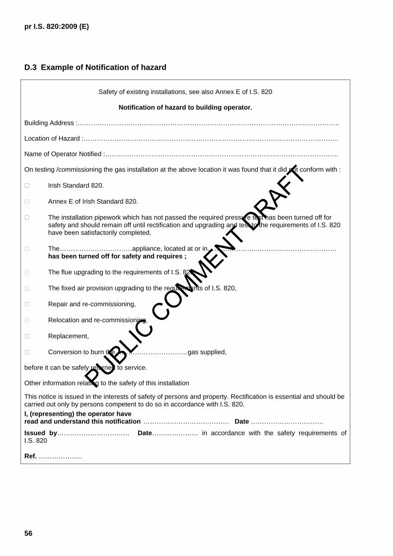
pr I.S. 820:2009 (E)
56
D.3 Example of Notification of hazard
Safety of existing installations, see also Annex E of I.S. 820
Notification of hazard to building operator.
Building Address :………………………………………………………………………………………………………..
Location of Hazard :……………………………………………………………………………………………………..
Name of Operator Notified :…………………………………………………………………………………………….
On testing /commissioning the gas installation at the above location it was found that it did not conform with :
Irish Standard 820.
Annex E of Irish Standard 820.
The installation pipework which has not passed the required pressure test has been turned off for safety and should remain off until rectification and upgrading and test to the requirements of I.S. 820 have been satisfactorily completed.
The……………………………appliance, located at or in…………………..……………………………… has been turned off for safety and requires ;
The flue upgrading to the requirements of I.S. 820,
The fixed air provision upgrading to the requirements of I.S. 820,
Repair and re-commissioning,
Relocation and re-commissioning,
Replacement,
Conversion to burn the……………………………gas supplied,
before it can be safely returned to service.
Other information relating to the safety of this installation
This notice is issued in the interests of safety of persons and property. Rectification is essential and should be carried out only by persons competent to do so in accordance with I.S. 820. I, (representing) the operator have read and understand this notification ………………………………… Date ……………………………
Issued by…………………………… Date………………… in accordance with the safety requirements of I.S. 820
Ref. ………………..
PUBLIC C
OMMENT DRAFT

pr I.S. 820:2009 (E)
57
Annex E (normative)
Safety inspections of existing non-domestic installations
E.1 General
This annex sets out a method by which existing installations, already constructed and commissioned shall be inspected to ensure that it is safe for continued operation.
The inspection shall be carried out by a competent person authorised to do so by the operator on an occasional basis or as part of a planned maintenance programme, see 10.2, or
Competent persons shall, on behalf of the gas supplier, carry out an inspection:
⎯ in the immediate aftermath of a reported abnormal situation (see 10.3), or
⎯ prior to re-supplying a premises or part thereof (see 10.7).
E.2 Scope of inspection
The following essentials to the safe use of gas and gas appliances shall be checked:
⎯ Pipework: soundness of pipework, and visible condition of exposed sections;
⎯ Appliances: visual evidence of appropriate location, availability of sufficient combustion air and the existence of a connected effective flue, when required.
E.3 Required actions
E.3.1 Should the inspection reveal an unsafe situation the installation shall be taken out of use or shall not be brought into use pending full rectification and the issuing of a declaration of conformance, see 9.0.
E.3.2 Should the inspection reveal aspects of the installation which do not conform to the requirements of this standard or which are otherwise found unsatisfactory but is deemed safe to operate then a Notification of Hazard shall be issued to the operator by the competent, authorised person conducting the inspection.
E.3.3 A specimen of a Notification of Hazard is contained in Annex D.3
E.4 Soundness test of an existing installation
E.4.1 When soundness testing an existing installation a fitness test as required in 7.1.4 is considered appropriate.
E.4.2 Appliances or other parts of the installation, which can be shut down separately and secured in the closed position, may be isolated and the gas supply provided/restored to the remaining sections of the installation which prove to be sound.
PUBLIC C
OMMENT DRAFT

pr I.S. 820:2009 (E)
58
E.5 Visual inspection of exposed pipework
E.5.1 There shall be no evidence of physical damage or mechanical failure.
E.5.2 The integrity of the pipework shall not be threatened by corrosion.
E.6 Appliance location
A visual check shall establish that the appliance is located in accordance with manufacturer's recommendations, with the requirements of this standard and, bearing in mind site conditions, a location where it can be operated safely.
E.7 Combustion air
A visual inspection/ measurement shall establish that sufficient combustion air is permanently available to the appliance in accordance with manufacturer's recommendations. Where there is doubt about the adequacy of the permanent supply of combustion air, reference shall be made to clause 11.7 of this standard.
E.8 Adequacy of connected flue
E.8.1 Atmospheric flues, with the appliance operating or with the introduction of an available alternative heat source, shall be checked by appropriate means to establish that a positive up draft is available and there is no noticeable spillage from the appliance.
E.8.2 Flues which operate with forced or assisted draft shall be checked to establish that the appliance served can not be operated in the event of fan failure/non-availability.
E.8.3 When reasonably practical, flues shall be visually inspected to establish the absence of corrosion, damage or other deterioration which might affect the structure or integrity of the flue.
E.8.4 Where reasonably practical, the flue terminal shall be inspected to confirm that it is correctly located and the opening is not obstructed and is free from combustible material.
PUBLIC C
OMMENT DRAFT
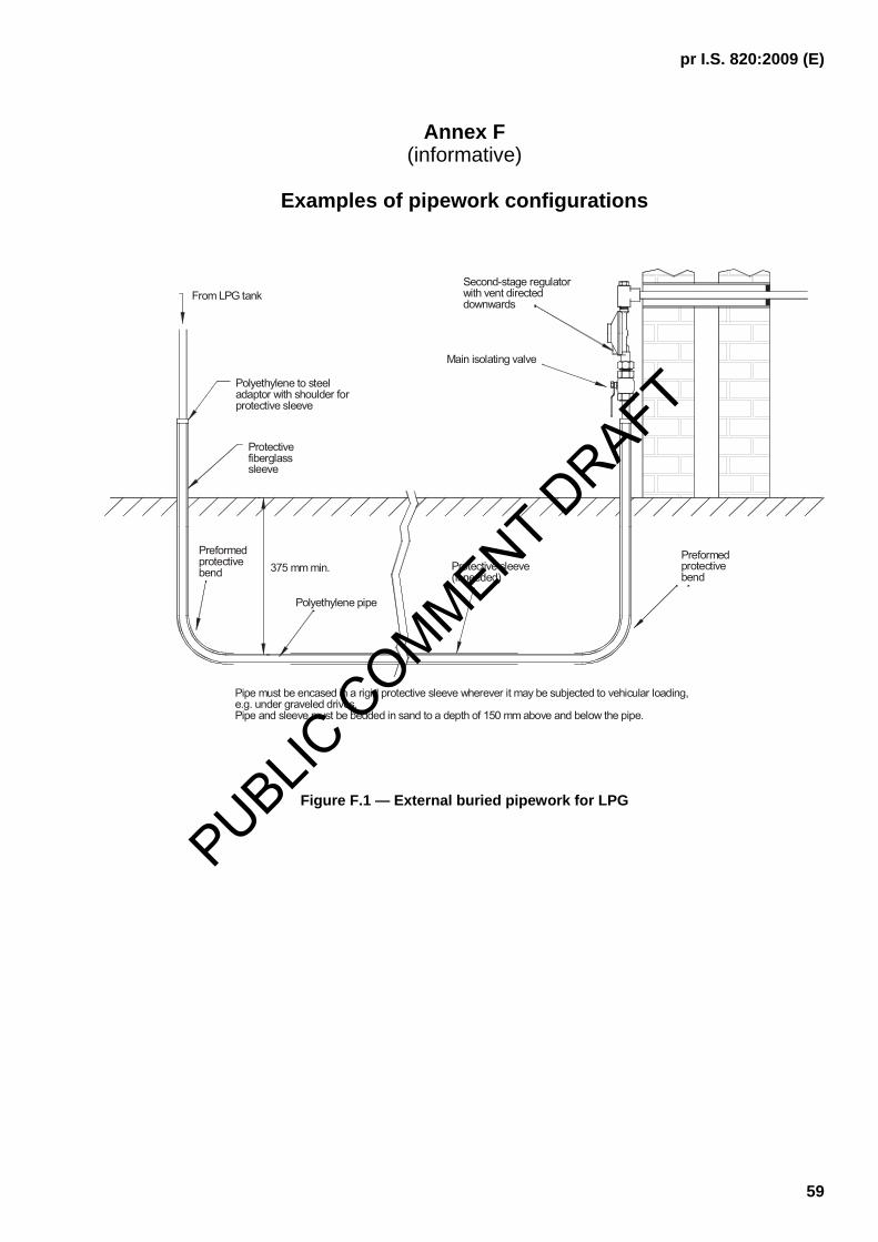
pr I.S. 820:2009 (E)
59
Annex F (informative)
Examples of pipework configurations
375 mm min.
Polyethylene to steeladaptor with shoulder forprotective sleeve
Preformedprotectivebend
Protectivefiberglasssleeve
Polyethylene pipe
From LPG tank
Pipe and sleeve must be bedded in sand to a depth of 150 mm above and below the pipe.
Pipe must be encased in a rigid protective sleeve wherever it may be subjected to vehicular loading, e.g. under graveled drives.
Protective sleeve(if needed)
Preformedprotective
bend
Second-stage regulatorwith vent directeddownwards
Main isolating valve
Figure F.1 — External buried pipework for LPG
PUBLIC C
OMMENT DRAFT

pr I.S. 820:2009 (E)
60
Steel sleeve to terminate 25 mmfrom FFL. Mastic sealant to be injectedbetween sleeve and service pipe
PE/metalic transition fitting
FGL
25 mm min.
300 mm
375 mm min.cover
DPC
Outer wallGrout between sleeveand concrete
25 mm min.
Grout
FFL
Sealant
Note 1 The underground and underfloor section of metallic pipe and the transition fitting shall be fully coated with anti-corrosive protection material
Note 2 Damp floor course shall be sealed to the sleeve
Note 3 Pipework entering a building should not compromise any radon protection.
Figure F.2 — Below ground entry for natural gas
PUBLIC C
OMMENT DRAFT

pr I.S. 820:2009 (E)
61
Left open tothe outside
Pipe clip
Sleeve
Outside wall
Grout
Inside wall
Insulation
Cavity
Temperature resistantmastic between pipe andsleeve, where it enters thebuilding, shall not cover joint between bend and pipe
90° bend
Figure F.3 — Example of pipe entry with 90º bend in cavity wall
SleeveTemperature resistant mastic
Grout
25 mm
Temperature resistantmastic between pipe and sleeve
Plaster ceiling
Grout Floor finish
Pipe
Figure 4 — Example of pipe entry through concrete ceiling or floor
PUBLIC C
OMMENT DRAFT

pr I.S. 820:2009 (E)
62
375 mm min.
GRP sleeve bend
3/4" BSPT male x 32 mm PE transition coupling c/w wallbracket
32 mm PEInstallation pipe
22 mm compressionx 3/4" BSP female
22 mm capillarysoldered elbow
22 mm copper pipe
150 mm min.
GRP coverfixed to wall
Figure F.5 — Above ground entry to building for natural gas
PUBLIC C
OMMENT DRAFT

pr I.S. 820:2009 (E)
63
Annex G (informative)
(Excerpt from) The Gas Appliance Directive (GAD)
Chapter 1 Of EU Directive 90/396/EEC
Scope, placing on the market and free movement.
Article 1.
1. This Directive shall apply to:
− appliances burning gaseous fuels used for cooking, heating, hot water production, refrigeration, lighting or washing and having, where applicable, a normal water temperature not exceeding 105 °C, hereinafter referred to as “appliances”. Forced draught burners and heating bodies to be equipped with such burners will also be considered as appliances,
− safety devices, controlling devices or regulating devices and sub-assemblies, other than forced draught burners and heating bodies to be equipped with such burners separately marketed for trade use and designed to be incorporated into an appliance burning gaseous fuel or assembled to constitute such an appliance, hereinafter referred to as “fittings”.
2. Appliances specifically designed for use in industrial processes carried out on industrial premises are excluded from the scope defined in paragraph 1.
3. For the purposes of this Directive, an appliance is said to be “normally used” when it is:
− correctly installed and regularly serviced in accordance with the manufacturer’s instructions;
− used with a normal variation in the gas quality and a normal fluctuation in the supply pressure, and
− used in accordance with its intended purpose or in a way which can be reasonably foreseen.
Article 2.
1. Member States shall take all necessary steps to ensure that the appliances referred to in Article 1 may be placed on the market and put into service only if, when normally used, they do not compromise the safety of persons, domestic animals and property.
2. Member States shall communicate the types of gas and corresponding supply pressures used on their territory to the other Member States and the Commission before 1 January 1991. They shall also communicate all changes in good time. The Commission shall ensure that this information is published in the Official Journal of the European Communities.
Article 3.
Appliances and fittings as referred to in Article 1 shall satisfy the essential requirements applicable to them set out in Annex 1.
Article 4.
1. Member States may not prohibit, restrict or impede the placing on the market and the putting into service of appliances which satisfy the essential requirements of this Directive.
PUBLIC C
OMMENT DRAFT

pr I.S. 820:2009 (E)
64
2. Member States may not prohibit, restrict or impede the placing on the market of fittings as referred to in Article 1 accompanied by a certificate as referred to in Article 8 (4).
Article 5.
1. Member States shall presume compliance with the essential requirements referred to in Article 3 of appliances and fittings when they conform to:
(a) the national standards applicable to them implementing the harmonised standards whose reference numbers have been published in the Official Journal of the European Communities. Members States shall publish the reference numbers of these national standards;
(b) the national standards applicable to them referred to in paragraph 2 in so far as, in the areas covered by such standards, no harmonised standards exist.
2. Member States shall communicate to the Commission the texts of their national standards as referred to in paragraph 1 (b) which they regard as complying with the essential requirements referred to in Article 3. The Commission shall forward these national standards to the other Member States. In accordance with the procedure provided for in Article 6 (2), it shall notify the Member States of those national standards which are presumed to conform with the essential requirements referred to in Article 3.
Article 6.
1. Where a Member State or the Commission considers that the standards referred to in Article 5 (1) do not entirely meet the essential requirements referred to in Article 3, the Commission or the Member State concerned shall bring the matter before the standing committee set up under Directive 83/189/EEC, hereinafter referred to as “the committee”, giving the reasons therefore. The committee shall deliver an opinion without delay.
In the light of the committee’s opinion, the Commission shall inform the Members States whether or not it is necessary to withdraw those standards from the publications referred to in Article 5 (1).
2. After receipt of the communication referred to in Article 5 (2), the Commission shall consult the committee. Upon receipt of the latter’s opinion, the Commission shall, within one month, inform the Member States whether or not the national standard(s) in question are to enjoy the presumption of conformity; if they are, the Member States shall publish the reference numbers of those standards. The Commission shall also publish them in the Official Journal of the European Communities.
Article 7.
1. Where a Member State finds that normally used appliances bearing the EC mark might compromise the safety of persons, domestic animals or property, it shall take all appropriate measures to withdraw those appliances from the market and prohibit or restrict their being placed on the market.
The Member State concerned shall immediately inform the Commission of any such measure, indicating the reasons for its decision and, in particular, whether non-compliance is due to:
(a) failure to meet the essential requirements referred to in Article 3, where the appliance does not correspond to the standards referred to in Article 5(1);
(b) incorrect application of the standards referred to in Article 5(1);
(c) shortcomings in the standards referred to in Article 5 (1) themselves.
2. The Commission shall enter into consultation with the parties concerned as soon as possible. Where, after such consultation, the Commission finds that any measure as referred to in paragraph 1 is justified, it shall immediately so inform the Member State that took the measure and the other Member States.
PUBLIC C
OMMENT DRAFT

pr I.S. 820:2009 (E)
65
Where the decision referred to in paragraph 1 is attributed to shortcomings in the standards, the Commission, after consulting the parties concerned, shall bring the matter before the committee within two months if the Member State which has taken the measures intends to maintain them, and shall initiate the procedures referred to in Article 6.
3. Where an appliance which does not comply bears the EC mark, the competent Member State shall take appropriate action against whomsoever has affixed the mark and shall inform the Commission and the other Member States thereof.
4. The Commission shall ensure that the Member States are kept informed of the progress and outcome of the procedures.
ANNEX 1
ESSENTIAL REQUIREMENTS
Preliminary remark
The obligations resulting from the essential requirements for appliances in this Annex also apply to fittings where the corresponding risk exists.
1. GENERAL CONDITIONS
1.1. Appliances must be so designed and built as to operate safely and present no danger to persons, domestic animals or property when normally used as defined in Article 1 (4) of this Directive.
1.2. When placed on the market, all appliances must:
− Be accompanied by technical instructions intended for the installer,
− Be accompanied by instructions for use and servicing, intended for users,
− Bear appropriate warning notices, which must also appear on the packaging.
The instructions and warning notices must be in the official languages of the Member States of destination.
1.2.1. The technical instructions intends for the installer must contain all the instructions for installation, adjustment and servicing required to ensure that those operations are correctly performed and that the appliance may be used safely. In particular the instructions must specify:
− The type of gas used,
− The gas supply pressure used,
− The flow of fresh air required:
− For combustion air supply,
− To avoid the formation of dangerous unburned gas mixtures for appliances not fitted with the device referred to in point 3.2.3,
− The conditions for the dispersal of combustion products,
− For forced draft burners and heating bodies intended to be equipped with such burners, their characteristics, the requirements for assembly, to assist compliance with the essential requirements applicable to finished appliances and, where appropriate, the list of combinations recommended by the manufacturer.
PUBLIC C
OMMENT DRAFT

pr I.S. 820:2009 (E)
66
1.2.2. The instructions for use and servicing intended for the user must contain all the information required for safe use, and must in particular draw the user’s attention to any restrictions on use.
1.2.3. The warning notices on the appliance and its packaging must clearly state the type of gas used, the gas supply pressure and any restriction on use, in particular the restriction whereby the appliance must be installed only in areas where there is sufficient ventilation.
1.3. Fittings intended to be part of an appliance must be so designed and built as to fulfil correctly their intended purpose when incorporated in accordance with the instructions for installation.
The instructions for installation, adjustment, operation and maintenance must be provided with the fittings concerned.
2. MATERIALS
2.1. Materials must be appropriate for their intended purpose and must withstand the technical, chemical and thermal conditions to which they will foreseeably be subjected.
2.2. The properties of materials that are important for safety must be guaranteed by the manufacturer or the supplier of the appliance.
3. DESIGN AND CONSTRUCTION
3.1. General
3.1.1. Appliances must be constructed that, when used normally, no instability distortion, breakage or wear likely to impair their safety can occur.
3.1.2. Condensation produced at the start-up and/or during use must not affect the safety of appliances.
3.1.3. Appliances must be so designed and constructed as to minimise the risk of explosion in the event of a fire of external origin.
3.1.4. Appliances must be so constructed that water and inappropriate air penetration into the gas circuit does not occur.
3.1.5. In the event of a normal fluctuation of auxiliary energy, appliances must continue to operate safely.
3.1.6. Abnormal fluctuation or a failure of auxiliary energy or its restoration must not lead to an unsafe situation.
3.1.7. Appliances must be so designed and constructed as to obviate hazards of electrical origin. In the area in which it applies, compliance with the safety objectives in respect of electrical hazards laid down in Directive 73/23/EEC(1) shall be equivalent to fulfilment of their requirement.
3.1.8. All pressurised parts of an appliance must withstand the mechanical and thermal stresses to which they are subjected without any deformation affecting safety.
3.1.9. Appliances must be so designed and constructed that failure of a safety, controlling or regulating device may not lead to an unsafe situation.
3.1.10. If an appliance is equipped with safety and controlling devices, the functioning of the safety devices must not be overruled by that of the controlling devices.
3.1.11. All parts of appliances which are set or adjusted at the stage of manufacture and which should not be manipulated by the user or the installer must be appropriately protected.
PUBLIC C
OMMENT DRAFT
pr I.S. 820:2009 (E)
67
3.1.12. Levers and other controlling and setting devices must be clearly marked and give appropriate instructions so as to prevent any error handling. Their design must be such as to preclude accidental manipulation.
3.2. Unburned gas release
3.2.1. Appliances must be so constructed that the gas leakage rate is not dangerous.
3.2.2. Appliances must be so constructed that gas release during ignition and re-ignition and after flame extinction is limited in order to avoid a dangerous accumulation of unburned gas in the appliance.
3.2.3. Appliances intended to be used in indoor spaces and rooms must be fitted with a special device which avoids a dangerous accumulation of unburned gas in such spaces or rooms.
Appliances which are not fitted with such devices must be used only in areas where there is sufficient ventilation to avoid a dangerous accumulation of unburned gas.
Member States may define on their territory adequate space ventilation conditions for the installation of such appliances, bearing in mind the features peculiar to them.
Large-scale kitchen appliances and appliances powered by gas containing toxic components must be equipped with the aforesaid device.
3.3. Ignition
Appliances must be so constructed that, when used normally:
− ignition and re-ignition is smooth,
− cross-lighting is assured.
3.4. Combustion
3.4.1 Appliances must be so constructed that, when used normally, flame stability is assured and combustion products do not contain unacceptable concentration of substances harmful to health.
3.4.2. Appliances must be so constructed that when used normally, there will be no accidental release of combustion products.
3.4.3. Appliances connected to a flue for the dispersal of combustion products must be so constructed that in abnormal draught conditions there is no release of combustion products in a dangerous quantity into the room concerned.
3.4.4. Independent flueless domestic heating appliances and flueless instantaneous water heaters must not cause, in the room or space concerned, a carbon monoxide concentration likely to present a danger to the health of persons exposed, bearing in mind the foreseeable duration of their exposure.
3.5. Rational use of energy
Appliances must be so constructed as to ensure rational use of energy reflecting the state of the art and taking into account safety aspects.
3.6. Temperatures
3.6.1. Parts of appliances which are intended to be placed in close proximity to the floor or other surfaces must not reach temperatures which present a danger in the surrounding area.
PUBLIC C
OMMENT DRAFT

pr I.S. 820:2009 (E)
68
3.6.2. The surface temperature of knobs and levers of appliances intended to be manipulated must not present a danger to the user.
3.6.3. The surface temperatures of external part of appliances intended for domestic use, with the exception of surfaces or parts which are associated with the transmission of heat, must not under operating conditions present a danger to the user and in particular to children, for whom an appropriate reaction time must be taken into account.
3.7. Foodstuffs and water used for sanitary purposes.
Without prejudice to the Community rules in this area, materials and components used in the construction of an appliance, which may come into contact with food or water used for sanitary purposes, must not impair their quality.
PUBLIC C
OMMENT DRAFT

pr I.S. 820:2009 (E)
69
Annex H (normative)
Service shaft ventilation
H.1 Ventilation and sub-division of vertical service shafts (other than ventilation ducts)
In the event of fire breaking into or originating in a vertical service shaft the smoke and hot gases may eventually fill the service shaft completely. The temperature of the hot gases, particularly at the top may be sufficient to set fire to any combustible materials and seriously distort the services within the enclosures. Furthermore, the smoke may exploit any weakness in gas tightness to escape into the other floors or compartments of the building. Thus, permanent ventilation shall be provided at the top of the service shaft to the external air so that heat and smoke from a fire may be safely dispelled. Where a service shaft extends to the top of the building an opening for natural ventilation is usually easily arranged and shall be not less than 5 000 mm2
or 1/500 of cross-sectional area of the service shaft whichever is the greater.
H.2 Gas pipework within service shafts
Service shafts carrying gas pipes shall be provided with adequate and suitable means of ventilation, top and bottom, preferably by natural means to prevent a dangerous accumulation of flammable gases which may occur as the result of a leakage. The ventilation shall discharge in a safe manner in the open air.
Where a vertical service shaft is divided horizontally by fire-stops or other means, each section between stops shall be treated as a separate service shaft.
Table H.1 — Relationship of gas installation pipes and other services in service shafts
Gas pipework / Other services in service shafts
Service Restriction Hot Water and Steam < 10 bar. Permitted Gas pipework shall be protected against corrosion, see 4.4.2 &
5.4.1. Hot Water and Steam > 10 bar. Not Permitted Ventilation and Air conditioning ducts in service shafts.
Permitted Gas pipework shall be enclosed in a purpose-constructed corrosion resistant sealed duct or sleeve with ventilation at each end to the outside. Before fitting the ventilation openings and putting into service the duct/sleeve shall be successfully pressure tested to the normal working pressure of the enclosed gas pipe, otherwise the pipe shall be continuous.
Cold and Chilled Water. Permitted Gas pipework shall be protected against corrosion, see 4.4.2 & 5.4.1.
Electricity. Permitted Adequate spacing and insulation shall be provided based upon the electrical voltage.
Telecommunications and Data. Permitted Adequate spacing shall be provided. Drainage. Permitted Gas pipework shall be protected against corrosion, see 4.4.2 &
5.4.1. Flammable Liquids and Gases. Permitted The spacing and ventilation in shaft shall reflect the hazard rating
of the other gases/liquids. Oxygen/Compressed Air. Not Permitted
PUBLIC C
OMMENT DRAFT

pr I.S. 820:2009 (E)
70
Annex I (normative)
Educational establishments - requirements
Requirements relating to the use of domestic and other small gas burning appliances used for educational purposes in schools and other educational establishments.
I.1 General
Specific requirements relating to the use, for educational purposes, of domestic type and other small gas burning appliances, for example domestic cookers, bunsen burners or small kilns, in schools and other educational establishments are addressed in this annex.
For requirements relating to the installation in schools and other educational establishments of non-domestic type appliances and associated installation pipework, for example a water boiler fitted to provide central heating to the school, reference shall be made to the appropriate clauses of this standard.
For requirements relating to the installation in schools and other educational establishments of domestic type appliances not intended for educational purposes, for example a domestic type gas cooker in a staff room, reference shall be made to I.S. 813. For requirements relating to the pipework up to and including the valve supplying such an appliance, reference shall be made to the appropriate clauses of this standard.
NOTE Every new cooker installed from the 1st January 2005 should be fitted with flame supervision or automatic re-ignition on all burners (see 11.2.4 and I.S. 813).
I.2 Supervision
In the preparation of this annex, it is assumed that pupils who access or operate gas appliances in schools or other educational establishments shall be, at all times, properly supervised by an appropriate person.
I.3 Isolation of gas supply
I.3.1 As required by this standard all gas installation pipework downstream of the point of delivery shall be designed and installed so as to permit its isolation from its supply in the event of an emergency.
I.3.2 All appliances shall be supplied through an isolation valve fitted in an accessible location, near to the appliance, see also 5.11 of this standard.
I.3.3 When designing an installation, or installing, appliances intended for teaching purposes in rooms or spaces in schools and other educational establishments:
a) every appliance shall be fitted with a flame supervision device on every burner, or
b) where an appliance is fitted without flame supervision on every burner (see I.1 note) or where taps intended for the connection of flexible tubing (see I.4) are installed, the supply pipework to each room or teaching space containing the appliances or taps shall be fitted with a purpose designed supervisory system to test the integrity of that section of installation pipework each time the device is activated. Each establishment shall have in place an operating procedure which includes, at a minimum, deactivation of the system at the end of each working day.
PUBLIC C
OMMENT DRAFT

pr I.S. 820:2009 (E)
71
I.4 Supervisory systems
I.4.1 General
I.4.1.1 When required by I.3, the supervisory system shall be designed and installed so as to ensure that it shall not be possible to establish the flow of gas to the supervised part of the installation until an integrity test has been automatically and successfully performed and the integrity of the supervised part of the installation confirmed.
I.4.1.2 The controlling device shall be in a tamper proof enclosure and any adjustable components shall be fitted within that enclosure.
I.4.1.3 Each room used for teaching shall have a supervisory system specific to that room. Any non-teaching room dedicated to only one teaching room shall be protected by that teaching room's supervisory system. If a non-teaching room is shared between two teaching rooms it shall be fitted with its own supervisory system.
I.4.1.4 Each supervisory system shall be operated by a key switch. The key switch shall be fitted at an appropriate point adjacent to the normal teaching position. Additional manually operated devices for use in emergency situations may also be included in the protective circuit controlling that isolating valve.
I.4.2 Commissioning the supervisory system
I.4.2.1 Testing and commissioning of this type of installation in schools shall be as described in clauses 6, 7 & 11. Additionally, after those required tests are satisfactorily completed, if a supervisory system is installed, it shall be calibrated. The limits of calibration shall reflect the volume of the system controlled and the period for which unlit gas can be safely allowed to flow to atmosphere during the proving phase of the systems operation. Following calibration the limits shall be set within the tamper proof enclosure.
I.4.2.2 The commissioning of the supervisory system shall be performed by a competent person (see note) and on its satisfactory completion a specific certificate shall be issued by the competent person to the operator, confirming the correct calibration, operation and testing of the system.
NOTE Commissioning is specialised work requiring specific training.
I.4.3 Use and maintenance
I.4.3.1 All supervisory systems shall be test operated annually. All components, including all visible pipework, flexible connectors, valves and appliances shall be inspected annually (see 10.1.3).
I.4.3.2 All supervisory systems shall be inspected, test operated and, if necessary, recalibrated by a competent person at intervals indicated by the manufacturer (see 10.1.4).
I.5 Appliance connection
I.4.1 When connecting bunsen burners using tubing or other appliances using flexible connectors, care shall be exercised to ensure the tubing or flexibles are not subjected to flames or in contact with surfaces at high temperature (125 C or above). The length of flexible hose shall be limited to the minimum practical for that application, see also 5.12.
I.4.2 Each flexible to a bunsen burner shall be supplied through a valve (e.g. lab tap) at the fixed connection. To prevent the valve being opened inadvertently, it shall incorporate a latching device to retain the valve in its closed position. The valve shall also be fixed by a foot plate or other means to prevent stress to the supply pipework by movement or rotation of the valve body during operation.
PUBLIC C
OMMENT DRAFT
pr I.S. 820:2009 (E)
72
Annex J (informative)
Guidelines for the construction of joints
J.1 General
This annex gives recommendations for jointing procedures, qualification of personnel and choice of materials relative to the correct execution of joints made by welding of steel, soldering and brazing of copper and its alloys and by fusion of polyethylene.
The general recommendations of this annex shall be applied to all welded, brazed, soldered joints and polyethylene fusion joints. In addition, specific recommendations given in Annex K, shall be applied as relevant to the jointing methods.
J.2 Operatives
Operatives shall be trained to perform joints fit for purpose.
Update training shall take place when necessary, and particularly for those operatives who make joints infrequently.
Training shall be performed by instructors who have wide practical and theoretical experience in the procedures. Instructors shall keep themselves up-to-date with the latest good practices, they shall be able to analyse the causes of failures, and be capable of organizing the resultant necessary additional training.
Training can comprise 'on the job' instruction under the direction of competent operatives.
Training should incorporate the following matters as a minimum, depending on the jointing methods:
⎯ pipes and fittings materials and thicknesses;
⎯ visual inspection of joints;
⎯ basics of relevant destructive and non-destructive testing;
⎯ selection, handling, storage and use of pipes, fittings, fluxes, filler rods and gases as appropriate;
⎯ suitable equipment (welding and fusion machines, clamps, ancillary tooling);
⎯ effect of weather conditions on joint quality;
⎯ preparation and cleanliness of pipe ends and fittings;
⎯ personal, third party and environmental safety.
Training should give the operative:
⎯ the ability to consistently perform satisfactory joints in compliance with corresponding procedures;
⎯ an awareness of and ability to implement safety procedures;
PUBLIC C
OMMENT DRAFT

pr I.S. 820:2009 (E)
73
⎯ an appreciation of what produces unsatisfactory joints.
Evidence shall be provided that training is appropriate for the installation work to be executed.
J.3 Quality control
Procedures shall be developed for the determination of any necessary testing of joints. These shall clearly specify how joints will be assessed as "pass or fail".
NOTE Quality control procedures may need to be agreed as part of any contract for the work.
Supervisors shall be trained, assessed and experienced in the jointing procedures being undertaken and all relevant safety matters. They shall be aware of quality procedures and be able to determine when additional on or off site investigation is necessary.
Unsatisfactory joints shall be replaced or repaired.
J.4 Documentation
Procedures shall be developed to retain records of instructor's qualifications, and training and assessment of operatives for checking by relevant persons.
Operative assessment shall be formally recorded and shall include all the appropriate parts of the training relevant to design pressure and jointing procedures.
PUBLIC C
OMMENT DRAFT

pr I.S. 820:2009 (E)
74
Annex K (informative)
Guidelines for the construction of welded, brazed, soldered joints, and
polyethylene fusion joints
K.1 Welding of steel
K.1.1 Materials
K.1.1.1 Pipes and fittings
Pipes and fittings shall be capable of being welded reliably under site conditions. The manufacturer will provide data on the weldability of the material and demonstrate weldability by tests when required in accordance with the specifier requirements.
The pipes and weldable steel fittings shall comply with I.S. EN 10208-1 or I.S. EN 10241 or I.S. EN 10255 as appropriate.
In order to ensure good weldability, it is recommended:
⎯ to limit the carbon equivalent maximum (CEmax) of pipes and fittings to 0,45 %;
⎯ to limit the maximum carbon content C of pipes and fittings to 0,21 % (see I.S. EN 10113-2);
⎯ to limit contents of other elements (e.g. P, S,...) which can affect welding;
⎯ to limit the SMYS to 360 N/mm² (SMYS = Specified minimum yield strength).
NOTE CEmax = C + 6
Mn +
5
VMoCr ++ +
15
NiCu + with content of C and other elements in %.
For steels not complying with these specifications, a weldability test shall be performed before any welding work commences.
NOTE Reference can be made to I.S. EN 1011-2 for welding of ferritic steels.
K.1.1.2 Welding consumables
Welding consumables shall be in accordance with the relevant European standards.
EXAMPLE I.S. EN 499 for shielded metal arc welding (SMAW), I.S. EN 440 for gas metal arc welding (GMAW).
K.1.2 Approval of the welding procedure
Evidence of the qualification of the welding procedure to be used shall be available for all the welding work on the joints. The welding procedure shall be submitted in accordance with I.S. EN ISO 15607 and either I.S. EN ISO 15609-1, or I.S. EN ISO 15614-1, or I.S. EN ISO 15610, or I.S. EN ISO 15611, or I.S. EN ISO 15612 or I.S. EN ISO 15613 as appropriate.
PUBLIC C
OMMENT DRAFT

pr I.S. 820:2009 (E)
75
K.1.4.1
K.1.3 Pipework with a maximum operating pressure (MOP) up to and including 0,1 bar and wall thickness of up to and including 4 mm
K.1.3.1 Welders
Welders shall be trained in accordance with J.2.
K.1.3.2 Quality control
Adequate seam quality shall be ensured, e.g. by visual inspection (See I.S. EN 970, with which the following is consistent).
Visual inspection of welds shall be carried out on the completed weld, with the naked eye or using a simple magnifying glass. The weld surface for examination shall be brightly illuminated and shall be free of grease, dirt, slag and any protective coatings.
The surface of the weld and the adjacent wall shall not contain cracks, notches or porosity and the area adjacent to the weld shall contain no electrode run points or other burnt areas. The weld surface shall be smooth. The acceptability of surface roughness shall depend on the type of weld and the application. There shall be no sharp transitions between weld beads.
K.1.4 Pipework with a maximum operating pressure (MOP) over 0,1 bar or wall thickness above 4 mm
Qualification of personnel
K.1.4.1.1 Welding operatives
For all welding work, operatives shall be qualified according to the appropriate qualified welding procedures, covering the techniques, material groups and dimension ranges concerned. Welding operatives shall be in possession of the valid qualification certificate.
A copy of the relevant certificates shall be provided upon request.
Welder qualification shall be performed according I.S. EN 287-1:1992 or to another appropriate national standard where I.S. EN 287-1:1992 is not relevant. In accordance with clause 8 of I.S. EN 287-1:1992, the acceptance criteria shall be defined according to the MOP of the pipework and the type of weld procedure.
NOTE Welding of pipework at operating pressure requires special training and qualification.
K.1.4.1.2 Weld quality supervisors
Persons in charge of quality control (supervisors) shall be identified. Persons performing quality control shall be competent in quality control matters. They shall be able to determine on site the quality of the joint and to decide when additional on- or off-site joint investigations are necessary.
K.1.4.1.3 Testing personnel
Destructive testing and non destructive testing personnel shall be appropriately qualified for the duties they are to perform according to an appropriate recognised international or national standard (e.g. I.S. EN 473).
All companies providing such personnel shall be certificated according to an appropriate standard (e.g. I.S. EN ISO/IEC 17020).
PUBLIC C
OMMENT DRAFT

pr I.S. 820:2009 (E)
76
K.1.4.2
K.1.4.3
K.2.1.1
Quality control
Adequate seam quality shall be ensured by visual inspection of the site welding work and/or by any non destructive and/or destructive tests (See I.S. EN 970, with which the following is consistent). The results of the tests shall be recorded.
Visual inspection of welds shall be carried out on the completed weld with the naked eye or using a simple magnifying glass. The weld surface for examination shall be brightly illuminated and shall be free of grease, dirt, slag and any protective coatings.
The surface of the weld and the adjacent wall shall not contain cracks, notches or porosity and the area adjacent to the weld shall contain no electrode run in points or other burnt areas. The weld surface shall be smooth. The acceptability of surface roughness shall depend on the type of weld and the application. There shall be no sharp transitions between weld beads.
When destructive testing is required, it shall be carried out according to recognised international or national standards.
Non destructive examination of welds is generally radiographically performed, carried out in accordance with an appropriate standard (e.g. for radiographic examination I.S. EN 444).
In order to ensure the required quality level, it is necessary to determine if non destructive testing is required and, when required, the number of points to be examined.
The quality of welds examined by non destructive testing shall be evaluated in accordance with an appropriate standard (e.g. I.S. EN 25817 for arc welding) The acceptance criteria shall be defined according to the MOP of the pipework and the type of weld procedure (e.g. arc welding, oxy-acetylene welding).
Documentation
Records of identification and qualification of welders and welding procedures, non-destructive or destructive tests, pipework materials and welding consumables shall be retained in order to comply with 7.1.1.
NOTE Reference should be made to I.S. EN 14717 in order to consider environmental aspects of welding for pipework.
K.2 Brazing and soldering of copper and copper alloys
K.2.1 Materials
Pipes and fittings
Pipes and fittings shall be capable of being brazed or soldered reliably under site conditions. The manufacturer will provide data on the ability to braze and solder the material.
It is recommended to use:
⎯ tubes conforming to I.S. EN 1057;
⎯ fittings conforming to I.S. EN 1254-1, I.S. EN 1254-4 and I.S. EN 1254-5, as appropriate.
NOTE When using fittings conforming to I.S. EN 1254-5, care should be taken to ensure that the tolerances and dimensions of the fittings do not adversely affect the joint quality. This may necessitate that additional design and quality control requirements are agreed with the manufacturer.
PUBLIC C
OMMENT DRAFT
pr I.S. 820:2009 (E)
77
K.2.1.2
K.2.3.1
K.2.3.2
K.2.4.1
K.2.4.2
Consumables
Brazing and soldering consumables shall be in accordance with the relevant European standards.
EXAMPLE I.S. EN 1044 or I.S. EN 29453 for filler materials, I.S. EN 1045 or EN ISO 9454-2 for brazing fluxes.
K.2.2 Brazing and soldering procedure
A procedure for the production of brazed or soldered joints shall be available for the materials to be joined and the fluxes and filler metals to be applied.
K.2.3 Pipework with a maximum operating pressure (MOP) up to and including 0,1 bar
Brazing and soldering operatives
Brazing and soldering operatives shall be trained in accordance with J.2.
Quality control
Adequate joint quality shall be ensured, e.g. by visual inspection (See for example I.S. EN 12799, with which the following is consistent).
Visual inspection of joints shall be carried out on the completed joint with the naked eye or using a simple magnifying glass. The joint surface for examination shall be brightly illuminated and shall be free of grease, dirt, flux, slag and any protective coatings.
The application of heat to form the joint shall not adversely affect the materials.
It is essential that the filler metal is visible and free of porosity defect around the complete circumference of the joint.
K.2.4 Pipework with a maximum operating pressure (MOP) over 0,1 bar
Qualification of personnel
K.2.4.1.1 Operatives
For all brazing and soldering work, operatives shall be qualified according to the appropriate qualified procedures covering the techniques, material groups and dimension ranges concerned. Operatives shall be in possession of the valid qualification certificate.
A copy of the relevant certificates shall be provided upon request.
Operative qualification shall be performed according to an appropriate standard.
K.2.4.1.2 Brazed joint quality supervisors
Persons in charge of quality control (supervisors) shall be identified. Persons performing quality control shall be competent in quality control matters. They shall be able to determine on site the quality of the joint and to decide when additional on- or off-site joint investigations are necessary.
Quality control
Adequate joint quality shall be ensured, e.g. by visual inspection of the brazing and soldering work (See for example I.S. EN 12799, with which the following is consistent).
PUBLIC C
OMMENT DRAFT

pr I.S. 820:2009 (E)
78
K.2.4.3
Visual inspection of joints shall be carried out on the completed joint with the naked eye or using a simple magnifying glass. The joint surface for examination shall be brightly illuminated and shall be free of grease, dirt, slag and any protective coatings.
The application of heat to form the joint shall not adversely affect the materials.
It is essential that the filler metal is visible and free of porosity defects around the complete circumference of the brazed or solder joint.
Documentation
Records of identification and qualification of operatives and brazing and soldering procedures, non-destructive tests, pipework materials, fluxes and filler metals shall be retained in order to comply with 7.1.1.
K.3 Fusion jointing of polyethylene
The following is consistent with I.S. EN 12007-2. For more detailed information, reference shall be made to that standard.
K.3.1 Materials
Pipes and fittings shall be capable of being jointed reliably under site conditions. The manufacturer will provide data on the ability to perform polyethylene fusion joints of the material and demonstrate this ability by tests when required in accordance with the specified requirements.
It is recommended to use
⎯ pipes complying with I.S. EN 1555-2;
⎯ fittings complying with I.S. EN 1555-3;
⎯ valves and ancillary equipment complying with I.S. EN 1555-4.
⎯ equipment for fusion jointing complying with ISO 12176-1 (Butt fusion) or ISO 12176-2 (Electrofusion).
K.3.2 Polyethylene fusion jointing procedure
Butt fusion procedure should, at least, contain the following information:
⎯ extreme ambient temperatures;
⎯ fusion cycle;
⎯ hotplate temperature;
⎯ pressures to apply at each step of the cycle;
⎯ time of each step (included cooling time);
⎯ average bead width.
Jointing procedure parameters for electrofusion fittings are normally developed by, and the responsibility of, the PE fitting manufacturer. The correct equipment (control box, clamps) and preparation (scraping, alignment, cleanliness) shall be applied. Fittings and equipment shall be compatible.
Extreme ambient temperatures to perform electrofusion shall be declared by the manufacturer.
PUBLIC C
OMMENT DRAFT

pr I.S. 820:2009 (E)
79
K.3.4.1
The jointing procedure shall be available on site at any time and exhibited on request to relevant persons.
NOTE Socket fusion is not recommended.
K.3.3 Qualification of personnel
Persons employed to perform or supervise jointing by electrofusion or butt fusion shall be trained in accordance with J.2.
NOTE Reference should be made to EN 13067.
K.3.4 Quality control
Butt fusion joint
Visual examination shall be carried out on each joint with the following criteria:
Bead shape: the bead depression 'A' as displayedin Figure K.1 shall not extend below the pipe surface, the surface shall be smooth and symmetrical around the entire pipe circumference (different melt flow rate (MFR) materials can give non symmetrical beads).
Figure K.1 — Bead shape
Alignment: pipes, fittings, valves shall be as closely aligned as possible. Normally, a 10 % of wall thickness mismatch ('v', Figure K.2) is allowable but particular care shall be given to pipes with a thickness under 10 mm.
Bead width: 'B' (Figure K.2) is indicative of a well performed joint, but it depends on procedure, MFR and production method (extrusion or injection moulding). Once the last two variables are defined, 'B' is a good indicator if the procedure has been correctly applied. 'B' variations along the circumference indicate poor conditions of the fusion equipment.
Figure K.2 — Bead width
External beads can be removed with appropriate tooling, and checked for contamination or lack of fusion. A thin root and curled bead can lead to more investigation on the joint (e.g. transverse tensile testing). Removed beads can be kept as one of the proofs of the joint quality.
PUBLIC C
OMMENT DRAFT

pr I.S. 820:2009 (E)
80
K.3.4.2 Electrofusion joint
K.3.4.2.1 For electrofusion sockets (e.g. couplers), the quality control shall include the following items:
⎯ pipes and fittings alignment (permissible misalignment is given in I.S. EN 1555-5);
⎯ adequate scraping (deep enough and covering the entire circumference);
⎯ penetration : marking shall give evidence that pipe or spigot are correctly coupled with socket;
⎯ cleanliness : no grease or dirt shall be present near or within the fusion interface (immediately before or after the application of the fusion cycle);
⎯ no melt exudation outside of the fitting;
⎯ heating indicators (if present) shall comply with the instructions given by the manufacturer;
⎯ clamps, if necessary, shall not be removed before the cooling time has elapsed;
⎯ no abnormal displacement (after fusion) of electric wire.
K.3.4.2.2 For electrofusion saddles (e.g. 'stack loaded' tapping tees, branch saddles) the quality control shall include the following items:
⎯ adequate scraping (deep enough and covering the entire fusion area);
⎯ the stack of the saddle shall be perfectly radial to the pipe;
⎯ no rotation or movement shall occur during the application of the entire fusion cycle (including cooling time);
⎯ no grease or dirt shall be present near or within the fusion interface (immediately before or after the application of the fusion cycle);
⎯ the fitting shall not collapse on the pipe;
⎯ no melt exudation outside of the fitting;
⎯ visual inspection of heating indicators (if present) shall be in compliance with the instructions given by the manufacturer;
⎯ clamps, if necessary, shall not be removed before the cooling time has elapsed;
⎯ application of ancillary tooling shall not result in significant damage to pipe.
PUBLIC C
OMMENT DRAFT

pr I.S. 820:2009 (E)
81
Bibliography
[1] I.S. EN 287-1 Qualification test of welders - Fusion welding - Part 1: Steels
[2] I.S. EN 440, Welding consumables - Wire electrodes and deposits for gas shielded metal arc welding of non alloy and fine grain steels - Classification
[3] I.S. EN 444, Non-destructive testing - General principles for radiographic examination of metallic materials by x- and gamma-rays
[4] I.S. EN 473, Non-destructive testing - Qualification and certification of ndt personnel - General principles
[5] I.S. EN 499, Specification for dedicated liquefied petroleum gas appliances - Domestic flueless space heaters (including diffusive catalytic combustion heaters)
[6] I.S. EN 970, Non-destructive examination of fusion welds - Visual examination
[7] I.S. EN 1011-2, Welding - Recommendations for welding of metallic materials - Part 2: Arc welding of ferritic steels
[8] I.S. EN 1044, Brazing - Filler metals
[9] I.S. EN 1045, Brazing - Fluxes for brazing - Classification and technical delivery conditions
[10] I.S. EN 1254-1, Copper and copper alloys - Plumbing fittings - Part 1: Fittings with ends for capillary soldering or capillary brazing to copper tubes
[11] I.S. EN 1254-4, Copper and copper alloys - Plumbing fittings - Part 4: Fittings combining other end connections with capillary or compression ends
[12] I.S. EN 1254-5, Copper and copper alloys - Plumbing fittings - Part 5: Fittings with short ends for capillary brazing to copper tubes
[13] I.S. EN 1555-2, Plastics piping systems for the supply of gaseous fuels - Polyethylene (PE) - Part 2: Pipes
[14] I.S. EN 1555-4, Plastics piping systems for the supply of gaseous fuels - Polyethylene (PE) - Part 4: Valves
[15] I.S. EN 1555-5, Plastics piping systems for the supply of gaseous fuels - Polyethylene (PE) - Part 5: Fitness for purpose of the system
[16] I.S. EN 10113-2, Hot-rolled products in weldable fine grain structural steels - Part 2: Delivery conditions for normalized/normalized rolled steels
[17] I.S. EN 10208-1, Steel pipes for pipelines for combustible fluids - Technical delivery conditions – Part 1: Pipes of requirement class A
[18] I.S. EN 10255, Non-Alloy steel tubes suitable for welding and threading - Technical delivery conditions
[19] I.S. EN 12007-2, Gas supply systems - Gas pipelines for maximum operating pressure up to and including 16 bar - Part 2: Specific functional recommendations for polyethylene (MOP up to and including 10 bar)
[20] I.S. EN 12799, Brazing - Non-destructive examination of brazed joints
PUBLIC C
OMMENT DRAFT

pr I.S. 820:2009 (E)
82
[21] I.S. EN 13067, Plastics welding personnel - Qualification testing of welders - Thermoplastics welded assemblies
[22] I.S. EN 14717, Welding and allied processes - Environmental check list
[23] I.S. EN 25817, Arc-welded joints in steel - Guidance on quality levels for imperfections (ISO 5817)
[24] I.S. EN 29453, Soft soldering fluxes - Chemical compositions and forms (ISO 9453)
[25] I.S. EN ISO 9454-2, Soft soldering fluxes - Classification and requirements - Part 2: Performance requirements (ISO 9454-2)
[26] ISO 12176-1, Plastics pipes and fittings - Equipment for fusion jointing polyethylene systems - Part 1: Butt fusion
[27] ISO 12176-2, Plastics pipes and fittings - Equipment for fusion jointing polyethylene systems – part 2: Electrofusion
[28] I.S. EN ISO 15607, Specification and qualification of welding procedures for metallic materials - General rules (ISO 15607)
[29] I.S. EN ISO 15609-1, Specification and qualification of welding procedures for metallic materials - Welding procedure specification - Part 1: Arc welding (ISO 15609-1)
[30] I.S. EN ISO 15614-1, Specification and qualification of welding procedures for metallic materials - Welding procedure test - Part 1: Arc and gas welding of steels and arc welding of nickel and nickel alloys – Amendment 1 (ISO 15614-1)
[31] I.S. EN ISO 15610, Specification and qualification of welding procedures for metallic materials - Qualification based on tested welding consumables (ISO 15610)
[32] I.S. EN ISO 15611, Specification and qualification of welding procedures for metallic materials - Qualification based on previous welding experience (ISO 15611)
[33] I.S. EN ISO 15612, Specification and qualification of welding procedures for metallic materials - Qualification by adoption of a standard welding procedure (ISO 15612)
[34] I.S. EN ISO 15613, Specification and qualification of welding procedures for metallic materials - Qualification based on pre-production welding test (ISO 15613)
[35] I.S. EN ISO/IEC 17020, General criteria for the operation of various types of bodies performing inspection (ISO/IEC 17020) PUBLIC
COMMENT D
RAFT


![BASF Polyurethane - Walltite - NSAI · 2020. 8. 11. · BRE report BR 497 [3] and I.S. EN ISO 10211 [4]. As a result, best practice has been observed to limit heat loss due to thermal](https://static.fdocuments.us/doc/165x107/61335a03dfd10f4dd73b0811/basf-polyurethane-walltite-nsai-2020-8-11-bre-report-br-497-3-and-is.jpg)