Quantification of true displacement using apparent displacement

Available online at www.sciencedirect.com
ScienceDirect
Structural Integrity Procedia 00 (2016) 000–000 www.elsevier.com/locate/procedia
2452-3216 © 2016 The Authors. Published by Elsevier B.V. Peer-review under responsibility of the Scientific Committee of ECF21.
21st European Conference on Fracture, ECF21, 20-24 June 2016, Catania, Italy
Investigation on the rotational deformation of SEB specimens with various crack length to width ratio
Tomoya Kawabata*a, Tetuya Tagawab, Yoichi Kayamoric, Shuji Aiharaa
and Yukito Hagiharad a The University of Tokyo, Hongo7-3-1, Bunkyo, Tokyo 113-8656, Japan
b JFE Steel Corporation, Chiba 260-0835, Japan c Nippon Steel & Sumitomo Metal Corporation, Amagasaki 660-0891, Japan c Formerly Department of Mechanical Engineering, Sophia University, Tokyo 102-8554, Japan
Abstract
A new CTOD calculation formula was proposed by using a correction factor for the blunted crack tip in the authors’ previous report[Kawabata et al(2016)], and the calculated CTOD by the formula significantly corresponded to the actual CTOD obtained by FE analysis in the wide range of specimen thicknesses. However, the use of the CTOD formula is limited to the frequently used crack depth-to-width ratio, a0/W, between 0.45 and 0.55, and this does not satisfy a strong demand for wider a0/W range. Meanwhile, ISO15653 covers a wider range of a0/W between 0.10 and 0.70, where J-based CTOD calculation formula has been specified in the annex-E of ISO15653. In this context, the plastic hinge model was investigated for a0/W between 0.05 and 0.70 by using FE analysis, and the analytical deformation of SEB specimens revealed that the plastic hinge model was applicable to the specimens even though their a0/W were out of the frequently used a0/W range from 0.45 and 0.55. Their rotational center points were almost steady when changing the applied load and the work hardening coefficient. © 2016 The Authors. Published by Elsevier B.V. Peer-review under responsibility of the Scientific Committee of ECF21.
Keywords: Toughness testing; Test standards; Crack tip opening displacement; Plastic hinge model; Rotational factor; Work hardening
1. Introduction
In the previous work [Tagawa et al(2010)], authors have pointed out that in some cases there exists large amount of difference between CTOD values calculated from J-integral (ASTM E1290-2002) and those from the plastic
* Corresponding author. Tel.: +81-3-5841-6517; fax: +81-3-5841-6517.
E-mail address: [email protected]
Draft Draft DraftDraft Draft Draft

2 Kawabata et al/ Structural Integrity Procedia 00 (2016) 000–000
hinge method (BS7448 part1-1991). In the following study[Tagawa et al(2014)], crack opening profiles were experimentally shown by using silicone rubber casting, and it was revealed that the profiles and CTOD were much affected by yield-to-tensile ratios resulted from work hardening behaviour. This means CTOD based on BS7448 probably differs from the actual CTOD in some work hardening conditions. However, the J-integral based CTOD of ASTM E1290 basically obtained by using two dimensional FEM, in which work hardening behavior is considered, has a problem that the actual CTOD at mid-thickness seems to be different from its two dimensional calculation result. In order to establish an accurate calculation formula, 3D FE analytical method was investigated for effective parametric study, and a new CTOD calculation formula was determined for SEB specimens with the a0/W of 0.50±0.05, as expressed in equation (1) [Kawabata et al(2016)]. Considering the further demand for the evaluation of CTOD in welded joints, the CTOD calculation formula should be applicable to SEB specimens for the wide range of a0/W because it is important to set the crack front location at the exact microstructure in various weld heat affected conditions.
𝛿𝛿𝑐𝑐𝑐𝑐𝑐𝑐 = 𝛿𝛿𝑒𝑒𝑐𝑐 + 𝛿𝛿𝑝𝑝𝑐𝑐 =𝐾𝐾2
𝑚𝑚𝜎𝜎𝑌𝑌𝐸𝐸+ 𝑓𝑓
𝑟𝑟𝑝𝑝(𝑊𝑊 − 𝑎𝑎)𝑟𝑟𝑝𝑝(𝑊𝑊 − 𝑎𝑎) + 𝑎𝑎 + 𝑧𝑧
𝑉𝑉𝑝𝑝 ・・ ・(1) 𝑚𝑚 = 4.9 − 3.5𝑌𝑌𝑌𝑌 𝑓𝑓 = 𝐹𝐹 ∙ 𝑓𝑓@𝐵𝐵=25 𝐹𝐹 = 0.8 + 0.2{−0.019(𝐵𝐵 − 25)} 𝑓𝑓@𝐵𝐵=25 = −1.4(𝑌𝑌𝑌𝑌)2 + 2.8(𝑌𝑌𝑌𝑌) − 0.35 𝑟𝑟𝑝𝑝 = 0.43
Nomenclature
a0 initial crack length B specimen thickness δel elastic component of CTOD δpl plastic component of CTOD CTODFEM, δFEM CTOD numerically calculated from a displacement between two ±45o intersection points from the
crack tip on the crack opening profile E Young’s modulus f correction factors for plastic component of CTODJWES
F correction factors for thickness K stress intensity factor m constraint factor n work hardening coefficient approximated by inverse number of yield-to-tensile ratio rp plastic rotational factor S Span of three points bend test Vg crack mouth opening displacement Vp plastic component of crack mouth opening displacement W specimen width YR yield-to-tensile ratio, σys /σuts
z height of knife edge α fitting parameter of the Swift type stress-strain relation 𝜀𝜀𝑝𝑝� equivalent plastic strain ν Poisson’s ratio σys yield strength σuts ultimate tensile strength 𝜎𝜎� equivalent stress

Kawabata et al / Structural Integrity Procedia 00 (2016) 000–000 3
Though the final aim of this study is to develop CTOD calculation formula under various a0/W conditions especially for the evaluation of a shallow crack, as the first step of the study, this paper reports whether the plastic rotational deformation exists or not. Effects of a0/W and work hardening properties on plastic rotational deformation were investigated from the standpoint of the use of the plastic hinge formula. This investigation starts from FE analysis for CTOD on the mid-thickness plane of each SEB specimen because it is difficult to observe the rotational deformation experimentally.
2. Numerical procedures
2.1 Models and method for FE analyses
In order to obtain universal findings which can be applied to many kinds of steel materials, constitutive equation of ordinary and normal 490MPa steel is used for finite element analysis. As representative of material properties variation, work hardening coefficient is changed for parametric study. Detailed configuration of stress-strain curve is based on the actual tensile test results[Tagawa et al(2014)] and extrapolated to high strain range using Swift equation. Also, when the parametric study of various work hardening coefficients, material constants which describes the configuration of Swift’s equation (equation (2)) are changed in conjunction each other. Tensile strength of constant value, 520MPa and Yield ratios (YR) are set to be 0.6 and 0.9 as shown in Table 1. Lueders strain is sometimes observed in actual steels but here no Lueders strain is assumed that means after yielding work hardening is occurred immediately.
𝜎𝜎� = 𝜎𝜎𝑦𝑦𝑦𝑦 �1 +𝜀𝜀𝑝𝑝�𝛼𝛼�𝑛𝑛
・・・(2)
Table 1 Constitutive equation used in FEM study.
Mark σys [MPa]
σuts [MPa]
YR (=σys/σuts)
Swift parameters
α n
YR60 312 520
0.6 9.09E-03 2.27E-01
YR90 468 0.9 1.82E-02 1.10E-01
In this study, mesh design around crack tip was completely same as the one in previous study which could offer smooth deformation configuration of crack face even in large amount of deformation, for example CTOD of 0.2mm. Also, in order to estimate accurately the coordination of rotation center, element size along the crack path in ligament is set to be sufficiently small, 0.1mm. In this study, thickness, B is constant value, 25mm which is the most popular. a0/W is changed from 0.05 to 0.70 in increments of 0.05 as exemplified in Fig.1. From FEM calculation, nodal reaction force, nodal displacement and strains are outputted and CTODFEM which is defined by opening profile of nodes backward of crack tip is calculated in each loading steps. Calculation process is ended at the CTOD of 0.2mm which is approximate indication of ductile crack that was observed on the unloaded section in the previous work[Tagawa et al(2014)] by the authors. This is based on the philosophy that CTOD does not work as fracture mechanics parameter after ductile crack initiation.
2.2 Examination of rotational factor, rp
In many previous studies on the rotational factor in the plastic hinge model on the consideration of the three point bend specimens, the proposed methods can be categorized into three patterns summarized as follows:
Fig.1 FE-models for SEB specimen with various a0/W.
xyz
0.70 0.65 0.60 0.55 0.50 0.45 0.40 0.35 0.30 0.25 0.20 0.15 0.10 0.05
W=2BCrack a0

4 Kawabata et al/ Structural Integrity Procedia 00 (2016) 000–000
(a) Rotational deformation observation method: the method of observation of the actual rotation in ligament region as shown in Fig.2(a). [Wu et al(1988)] applied the slip line field analysis in three point bend specimen with various length of cracks, where the slip lines growth were carefully observed during plastic deformation. As a result, the effect of a0/W on the rotational factors was revealed to be not strong, where the value was 0.4-0.5. However the observation was limited to the surface due to the restriction as an experiment. [Kawabata et al(2016)] showed rp at mid-thickness by 3D-elasto-plastic FEM analysis with various material stress strain curve responses that is especially focused on the effect of work hardening behavior. In the study, by using nodal displacement data on the mid-thickness plane, plastic rotational factors were calculated in several ways. Finally, rp obtained in these methods generally agreed in one value. However this previous report is limited in standard condition of a0/W, from 0.45 to 0.55. This study has an aspect of possibility of expansion of the identicalness to wide a0/W conditions which is confirmed in previous report.
(b) Extended line drawing method: By assuming straight crack flanks as shown in Fig. 2(b), the rotational center can be determined by linearly extending of the flat part to the direction of ligament and finding the cross-point of the line to the centerline of the specimen. This method was the first evidence for rotational factors in famous important paper in CTOD calculation formula establishment by [Ingham et al(1971). Characteristically, this is relatively easy to obtain the rotational factors experimentally. In the previous report[Kawabata et al(2016)], the result of method (b) shows good agreement with method (a) in the conditions of a0/W of 0.45~0.55. [Tanaka et al(1981)] and [Tsukamoto(1994)] also used this method for determination of rotational factors.
(c) Back calculation method using edge displacement and CTOD: If the real plastic term of CTOD is already known by some way, for example actual measurement by silicone rubber casting method or FEM analyses, rp can be back-calculated by applying ISO equation or equation(1). This method was applied in the researches by [Kirk et al(1993)], [Donato et al(2006)] and [Kayamori et al(2014)].
3. Results and discussion
3.1 Rotational deformation observation method [method a]
In order to investigate the existence of the constant rotational center, the first approach is the contour map of equivalent plastic strain of SEB specimens with elevated conditions of a0/W in mid-thickness plane. This can give general tendency of plastic deformation in the ligament region. Fig.3 is the examples of material of YR=0.6 at the CTODFEM of 0.1mm. This figure clearly exhibits the plastic deformation shows rotational way with a central focus on a point as this contour is constructed in logarithmic classification so there scarecely be equivalent plastic strain in blue or black colored area. For accurate determination of the coordination of rotation center, strain ditribution in the ligament region was thouroughly investigated. Considering the components of the calculation equation, rotation deformation should specify only in plastic deformation so plastic strain distribution is important here. Incremental value is used for the accurate evaluation of the coordination of the neutral point by bending. However there can be observed the zero-plastic-strain region around the center of the ligament in the distribution of plastic strain. Thus the rotation center cannot be computed only by the plastic strain distribution as explained above. This time through detailed comparison of the ditribution of plastic strain with that of whole strain it has been revealed that the
Fig.2 Schematic figure showing the definition of the rotational center
rp(W–a0)
a0
P
: Incremental plastic displacement
Linear extrapolation
Method (a)
rp(W–a0)
a0
P
Neutral point of plastic strain distribution
Method (b) Method (c)
δ45FEM,δSRC
Numerical back-calculation

Kawabata et al / Structural Integrity Procedia 00 (2016) 000–000 5
incremental value of the whole strain component including elastic term is sufficient to be used for the determination of rp. An example of the comparison is shown in Fig.3. By using the whole strain increment one unique value of the coordination of the rotation center can be determined as the whole strain distribution is monotonically diminished from the tension side to the compression side. Thus rp is calculated from whole strain distribution in opening direction in all conditions which is the combinations of 14 a0/W conditions and 2 kinds of material shown in Table1. Fig.4 exemplified rotational center position of several a0/W conditions of YR=0.6. It cleary shows that the rotational center locates at smaller x(W-a0) position as a0/W is increasing.
Fig.3 Contour map of equivalent plastic strain and strain increment
distribution along crack line in ligament
Fig.4 Strain increment distribution and change of rotational center
by a0/W Acoording to the summary about the change of rp of all
conditions during the deformation up to the level of CTODFEM=0.20mm, There seems to be relatively larger amout of the change of rp in the extreme cases of a0/W=0.05 or 0.7, however even in those cases, the amout of the change is limited to be less than 5% only. Fig.5 shows the summarized relationship between a0/W and the representative value of each conditions, (rp)av. which is computed by averaging the rp histories during CTODFEM=0.05~0.2mm. This figure clearly indicate that by decreasing a0/W (in other words, shallower specimen), rp is increased and its dependency shows almost same between two materials and simillar tendency with the observation by [Wu et al(1988)]. This can be stated that rp is less affected by YR. As the summary of this method, the numerical function of rp can be drawn by the equation(3) which is regression curve by least square fitting without the effect of YR.
𝑟𝑟𝑝𝑝 = 2.51 �𝑎𝑎0𝑊𝑊�4− 4.71 �
𝑎𝑎0𝑊𝑊�3
+ 2.88 �𝑎𝑎0𝑊𝑊�2− 0.79 �
𝑎𝑎0𝑊𝑊� + 0.53 ・・・(3)
3.2 Extended line drawing method [method b] This method has been applied by many researchers especially in early time study for first establishment of calculation formula of CTOD as described in 2.2. In order to set up the rp of BS type equation which is divided into elastic term and plastic one, extended line by which plastic component of CTOD has to be plastic deformation only without elastic component. However, in both of experimental methods and numerical analyses, sorting out plastic component is not so easy because the deformation proceeds in harmony with elastic and plastic component. It is noted that in previous researches shown in 2.2 extended lines were drawn by whole deformation so obtained rotational factors are not accurate for the current equation which is divided into two terms. Here, in order to sort out plastic component of extended line, the deformation information of cracked surface from the crack tip to the edge in
Fig.5 Summary of rotational factor calculated from strain
increment distribution along the ligament by 3D-FEM
0
0.2
0.4
0.6
0.8
1
1.2
1.4
1.6
1.8
0 0.2 0.4 0.6 0.8
Aver
aged
rp in
CTO
D ra
nge
of
δ=0.
05-0
.2m
m
a0/W
YR60YR90Regression[Eq.(3)]
�𝑉𝑉𝑔𝑔�𝑒𝑒𝑐𝑐 =6𝑃𝑃𝑃𝑃𝑎𝑎0𝐸𝐸𝐵𝐵𝑊𝑊2 𝑉𝑉(𝛼𝛼) ・・・(4)
𝑉𝑉(𝛼𝛼) = 1.45 − 2.18𝛼𝛼 + 13.71𝛼𝛼2 − 5.96𝛼𝛼3 − 36.9𝛼𝛼4 + 70.7𝛼𝛼5 ・・・(5)
𝛿𝛿𝑒𝑒𝑐𝑐(𝑥𝑥) =𝑥𝑥𝑎𝑎0�𝑉𝑉𝑔𝑔�𝑒𝑒𝑐𝑐 ・・・(6)
6 Kawabata et al/ Structural Integrity Procedia 00 (2016) 000–000
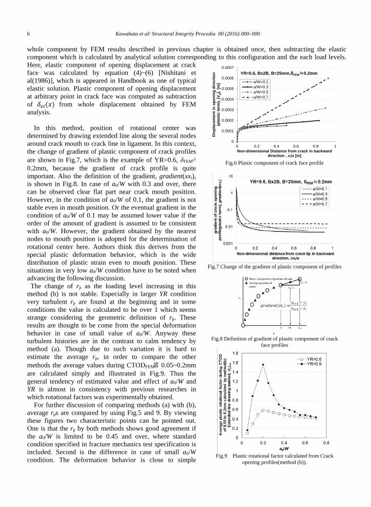
whole component by FEM results described in previous chapter is obtained once, then subtracting the elastic component which is calculated by analytical solution corresponding to this configuration and the each load levels. Here, elastic component of opening displacement at crack face was calculated by equation (4)~(6) [Nishitani et al(1986)], which is appeared in Handbook as one of typical elastic solution. Plastic component of opening displacement at arbitrary point in crack face was computed as subtraction of 𝛿𝛿𝑒𝑒𝑐𝑐(𝑥𝑥) from whole displacement obtained by FEM analysis.
In this method, position of rotational center was determined by drawing extended line along the several nodes around crack mouth to crack line in ligament. In this context, the change of gradient of plastic component of crack profiles are shown in Fig.7, which is the example of YR=0.6, δFEM≓0.2mm, because the gradient of crack profile is quite important. Also the definition of the gradient, gradient(xxi), is shown in Fig.8. In case of a0/W with 0.3 and over, there can be observed clear flat part near crack mouth position. However, in the condition of a0/W of 0.1, the gradient is not stable even in mouth position. Or the eventual gradient in the condition of a0/W of 0.1 may be assumed lower value if the order of the amount of gradient is assumed to be consistent with a0/W. However, the gradient obtained by the nearest nodes to mouth position is adopted for the determination of rotational center here. Authors think this derives from the special plastic deformation behavior, which is the wide distribution of plastic strain even to mouth position. These situations in very low a0/W condition have to be noted when advancing the following discussion. The change of rp as the loading level increasing in this
method (b) is not stable. Especially in larger YR condition very turbulent rp are found at the beginning and in some conditions the value is calculated to be over 1 which seems strange considering the geometric definition of rp. These results are thought to be come from the special deformation behavior in case of small value of a0/W. Anyway these turbulent histories are in the contrast to calm tendency by method (a). Though due to such variation it is hard to estimate the average rp, in order to compare the other methods the average values during CTODFEM・ 0.05~0.2mm are calculated simply and illustrated in Fig.9. Thus the general tendency of estimated value and effect of a0/W and YR is almost in consistency with previous researches in which rotational factors was experimentally obtained.
For further discussion of comparing methods (a) with (b), average rps are compared by using Fig.5 and 9. By viewing these figures two characteristic points can be pointed out. One is that the rp by both methods shows good agreement if the a0/W is limited to be 0.45 and over, where standard condition specified in fracture mechanics test specification is included. Second is the difference in case of small a0/W condition. The deformation behavior is close to simple
Fig.6 Plastic component of crack face profile
Fig.7 Change of the gradient of plastic component of profiles
Fig.8 Definition of gradient of plastic component of crack
face profiles
Fig.9 Plastic rotational factor calculated from Crack
opening profiles(method (b)).
0
0.0001
0.0002
0.0003
0.0004
0.0005
0.0006
0.0007
0 0.2 0.4 0.6 0.8 1
Dis
plac
emen
t in
open
ing
dire
ctio
n(p
last
ic te
rm),
[Vp]
i[m
]
Non-dimensional Distance from crack in backward direction , xi/a [m]
YR=0.6, Bx2B, B=25mm,δFEM≒0.2mm
a/W=0.1a/W=0.3a/W=0.5a/W=0.7

Kawabata et al / Structural Integrity Procedia 00 (2016) 000–000 7
bending problems so the rp become close to 0.5 in the sense of method (a). On the other hand, by method (b) rp shows very low value. In this meaning, it can be said that method (b) offers only “pretending” value in very shallow crack condition from viewpoint of the definition of rp. The mechanism of this situation may be derived from unstable gradient of crack face profile as shown in Fig.7. It is also focused the maximum value of rp becomes much higher in higher YR conditions. Considering that many actual steels estimated have more than 0.9 of YR and furthermore recent materials with high tensile strength sometimes shows close to 1 of YR, rp obtained by method (b) become very turbulent and looks unfit for calculation formula. 3.3 Back calculation method using Edge displacement and CTOD [method c]
When CTOD value is known by either experiment or FEM rp can be back-calculated by deformation of ISO formula or some other formula. As this is simple numerical back-calculation, obtained rp is not always supported by physical background. Here, equation (7) is the deformation of ISO formula and equation (8) is the deformation of equation (1) where rp is assumed to be unknown parameter. In order to apply equation (7), plastic component of CTOD, δp needs to be developed by subtracting elastic component from the total CTOD. Here, elastic component of CTOD is assumed to be first term of equation (1). When variation of calculated rp of various a0/W during the deformation process is clarified, it clearly shows that the variation is calm as same as method (a). rp of each a0/W conditions is organized by averaging from CTOD of 0.05mm to that of 0.2mm. Fig.10 shows the relationship between back-calculated rp and a0/W by using current ISO formula and its deformation. The tendency is different from previous two methods and similar as work of Kirk et al in which same procedure was used.
𝑟𝑟𝑝𝑝 =𝛿𝛿𝑝𝑝(𝑎𝑎0 + 𝑧𝑧)
�𝑉𝑉𝑝𝑝 − 𝛿𝛿𝑝𝑝�(𝑊𝑊 − 𝑎𝑎0) ・・・(7) 𝑟𝑟𝑝𝑝 =
𝛿𝛿𝑝𝑝(𝑎𝑎0 + 𝑧𝑧)�𝑓𝑓𝑉𝑉𝑝𝑝 − 𝛿𝛿𝑝𝑝�(𝑊𝑊− 𝑎𝑎0)
・・・(8)
Also as written above
authors have already developed CTOD calculation formula for standard a0/W conditions (a0/W=0.45-0.55) as shown in equation (1)
[Kawabata et al(2016)]. Here the plastic term factor, f expresses the dependency of YR on crack blunting profile. Assumed that this parameter f is constant for wide a0/W conditions, back-calculation is done by using plastic term of CTOD preliminarily divided by coefficient, f as described in equation (1). In this arrangement rp can be expressed in one line regardless of YR as shown in Fig.11. The reason and physical meaning of this agreement is not clear but important in engineering aspect. The function of regression curve can be drawn in equation (9).
𝑟𝑟𝑝𝑝 = −7.57 �𝑎𝑎0𝑊𝑊�4
+ 15.34 �𝑎𝑎0𝑊𝑊�3− 11.28 �
𝑎𝑎0𝑊𝑊�2
+ 3.76 �𝑎𝑎0𝑊𝑊� − 0.1 ・・・(9)
3.4 Discussion
For establishment of CTOD calculation formula based on plastic hinge assumption with wide range of a0/W, determination of the rp is quite important. As described above, three candidate methods are investigated and their applicability of the calculation formula is compared in Table 2. When the accuracy of calculation formula is considered, the variation under various loading level should be decreased. On this point method (b) has a decisive disadvantage. From a viewpoint of physical meaning, it can be said that method (c) has a problem. Consequently Method (a) is now good procedure for determination of rp, however detailed establishment of calculation formula has to be investigated in future study.
Fig.10 Plastic rotational factor back-calculated
from CMOD and [CTODFEM]p (method (c)). Fig.11 Plastic rotational factor back-calculated from CMOD and [CTODFEM]p /f (method (c)).

8 Kawabata et al/ Structural Integrity Procedia 00 (2016) 000–000
4. Concluding remarks
In this study, rp which is important part of CTOD calculation formula based on plastic hinge assumption is investigated with a final goal of establishment of the formula. 3D dynamic elasto-plastic FEM analysis for various a0/W conditions from 0.05 to 0.7 that was already validated by actual CTOD measurement by silicone casting method is used for deformation behaviour of three point bending specimen especially in mid-thickness plane which is important in the actual evaluation. Three methods for the determination of rp are investigated. Obtained result is listed below. 1) In every condition, it is clearly observed ligament area is rotationally deformed at a point. This can be the strong
motivation for continuous use for plastic hinge type calculation formula in determination of CTOD. 2) It is also confirmed that under the a0/W of 0.2, deformation mode transit from rotation only in ligament to whole
specimen rotation. 3) In method (a) where the actual coordination of rotational deformation is used, the rp is increased as the a0/W is
decreased and close to 0.5 that is the neutral plane of pure bending in case of simple beam problem. Variation during the deformation is quite small this is advantageous point for establishment of calculation formula.
4) In method (b) where crack opening profile and its extended line is used, the rp is so varied during loading. Especially in case of small a0/W conditions under 0.2, the variation is significantly enlarged. This is thought to be because there are large amount of opening displacement in small a0/W condition due to transition to whole deformation mode. This method has been applied from the early date of set-up of CTOD philosophy because this is experimentally easy to conduct.
5) In method (c) where back-calculation method by known CTOD and Vp is applied, rp are stable in targeted deformation level and especially by using coefficient f in which effect of YR is considered, rp is varied as a function only of a0/W.
Reference
Donato, G. H. B., Ruggieri, C., 2006. Estimation Procedures for J and CTOD Fracture Parameters Using Three-Point Bend Specimens 2006 International Pipeline Conference, Volume 3: Materials and Joining; Pipeline Automation and Measurement; Risk and Reliability, Parts A and B, Calgary, Alberta, Canada.
Ingham, T. GR., Egan, D. Elliott, Harrison, TC., 1971. The effect of Geometry on the interpretation of COD test data, Inst. Mech. Engng. C54/71:200.
Kawabata, T., Tagawa, T., Sakimoto, T., Kayamori, Y., Ohata, M., Yamashita, Y., Tamura, E., Yoshinari, H., Aihara, S., Minami, F., Mimura, H., Hagihara, Y., Proposal of a new CTOD calculation formula,Engineering Fracture Mechanics, accepted.
Kayamori, Y., Inoue, T., Hagihara, Y., 2014. Plastic rotational factor calculation for shallow notched SE(B) specimen, Material Science Forum 783-786, 2322-2326.
Kirk, M. T., Dodds Jr., R. H., J and CTOD Estimation Equations for Shallow Cracks in Single Edge Notch Bend Specimen Journal of testing evaluation 21, 223-238.
Tagawa, T., Kayamori, Y., Ohata, M., Handa, T., Kawabata, T., Yamashita, Y., Tsutsumi, K., Yoshinari, H., Aihara, S., Hagihara, Y., 2010. Comparison of CTOD standards: BS 7448-Part 1 and revised ASTM E1290, Engineering Fracture Mechanics 77(2), 327-336.
Tagawa, T., Kawabata, T., Sakimoto, T., Kayamori, Y., Ohata, M., Yamashita, Y., Tamura, E., Yoshinari, H., Aihara, S., Minami, F., Mimura, H., Hagihara, Y., 2014. Experimental measurements of deformed crack tips in different yield-to-tensile ratio steels, Engineering Fracture Mechanics 128, 157-170.
Nishitani, H., Noguchi, H., Mori, K., 1986. Analysis of Single-Edge-Cracked Specimen under Three- or Four-Point Bending by Body Force Doublet Method, Trans.Japan Soc. Mech. Engrs., 52(474), 539.543.
Shang-Xian Wu, S.X., Cotterell, B., Yiu-Wing Mai, 1988. Slip Line Solutions for Three-Point Notch-Bend Specimen, International Journal of Fracture 37, 13-29.
Tanaka, H., Ando, K., Sakai, Y., Ogura, N., 1981. Brittle crack initiation from shallow notch and Hot strain embrittlement, The Society of Materials Science, Japan, Committee on Fracture Mechanics, Proceedings for Fracture Mechanics Symposium, 147-151.
Tsukamoto, M., 1994. Effect of Initial Crack Length on Critical COD of Unstable Fracture with Stable Fibrous Crack Growth・Memoirs of the Faculty of Education, Kumamoto University. Natural science 43, 153-162.
Table 2 Comparison of three methods for determination of rp Method Procedure advantage Disadvantage
(a)
Rotational deformation observation method
・ A little variation during the target loading range
・ Correspondence with actual deformation
-
(b) Extended line drawing method
・ Consistency from previous research which contributed to the first foundation of the formula.
・ A lot of variation during the target loading range
(c)
Back calculation method using Edge displacement and CTOD
・ A little variation during the target loading range
・ No physical background