
DP4 - AHR International · II Formula Symbols and Designations Formula Symbol Unit Designation A...
44
DP4 Maintenance-free Designer·s Handbook GLACIER GARLOCK BEARINGS
Transcript of DP4 - AHR International · II Formula Symbols and Designations Formula Symbol Unit Designation A...
DP4Maintenance-free
Designer´s Handbook
GLACIER GARLOCKBEARINGS

I
QualityAll the products described in this handbook are manufactured under DIN ISO 9001/2 or QS 9000 approved qualitymanagement systems.
© by GLACIER GARLOCK BEARINGS
II
Formula Symbols and Designations
FormulaSymbol Unit Designation
A mm2 Surface area of DP4 bearing
AM mm2 Surface area of mating surface in con-tact with DP4 bearing (slideway)
aB - Bearing size factor
aC - Application factor for bore burnishing or machining
aE - High load factor
aE1 - Specific load factor (slideways)
aE2 - Speed, temperature and material factor (slideways)
aE3 - Relative contact area factor (slideways)
aL - Life correction constant
aM - Mating surface material factor
aT - Temperature application factor
B mm Nominal bush length
C 1/min Dynamic load frequency
CD mm Installed diametral clearance
Ci mm Inside chamfer
Co mm Outside chamfer
CT - Total number of dynamic load cycles
DC mm Diameter of burnishing tool
Dfl mm Nominal bush flange OD
DH mm Housing diameter
Di mm Nominal bush and thrust washer ID
Di,a mm Bush ID when assembled in housing
DJ mm Shaft diameter
DNth nvt Max. thermal neutron dose
Do mm Nominal bush and thrust washer OD
dD mm Dowel hole diameter
dL mm Oil hole diameter
dP mm Pitch circle diameter for dowel hole
Dg Gy Max. Gamma radiation dose Gy = J/kg
F N Bearing load
Fch N Test load
Fi N Insertion force
f - Coefficient of friction
L mm Strip length
LH h Bearing service life
LS mm Length of stroke (slideway)
N 1/min Rotational speed
NE 1/min Equivalent rotational speed for oscilla-ting movement
Nosz 1/min Oscillating movement frequency
p N/mm2 Specific load
plim N/mm2 Specific load limit
psta,max N/mm2 Maximum static load
pdyn,max N/mm2 Maximum dynamic load
Q - Number of load/movement cycles
Ra µm Surface roughness (DIN 4768, ISO/DIN 4287/1)
ROB Ω Electrical resistance
S3 mm Bush wall thickness
Sfl mm Flange thickness
SS mm Strip thickness
ST mm Thrust washer thickness
T °C Temperature
Tamb °C Ambient temperature
Tmax °C Maximum temperature
Tmin °C Minimum temperature
ta mm Depth housing recess
U m/s Sliding speed
W mm Strip width
Wu mm Maximum usable strip width
ZT - Total number of cycles
α1 1/106K Coefficient of linear thermal expansion parallel to surface
α2 1/106K Coefficient of linear thermal expansion normal to surface
σc N/mm2 Compressive yield strength
λ W/mK Thermal conductivity
ϕ ° Angular displacement
η Ns/mm2 Dynamic viscosity
FormulaSymbol Unit Designation
Contents
3
ContentsQuality . . . . . . . . . . . . . . . . . . . . . IFormula Symbols andDesignations . . . . . . . . . . . . . . . . II
1 Introduction . . . . . . . . . . . 4
2 Basic Forms . . . . . . . . . . . 4
3 Structure andComposition . . . . . . . . . . 5
4 Properties . . . . . . . . . . . . . 54.1 Physical and Mechanical
Properties . . . . . . . . . . . . . . . . . . 54.2 Chemical Properties . . . . . . . . . 54.3 Frictional Properties . . . . . . . . . 6
5 Bearing Performance . . . 85.1 McPherson Strut Applications . 8
Wear and Friction Properties . . . . 8McPherson Strut Wear Test . . . . 8McPherson Strut Friction Test . . . 9Cavitation Erosion Resistance . . 10Cavitation Erosion Test . . . . . . . 10Flow Erosion Resistance . . . . . . 11Flow Erosion Test . . . . . . . . . . . 11
5.2 Hydraulic Applications . . . . . . 12Glacier Garlock BearingsJupiter Test Rig . . . . . . . . . . . . . 12Lubricated Wear Test . . . . . . . . 12
5.3 Dry Wear Performance . . . . . . 13Design Factors . . . . . . . . . . . . . . 13Specific Load p . . . . . . . . . . . . . 13Specific Load Limit plim . . . . . . . 13Sliding Speed U . . . . . . . . . . . . . 14Calculation of Sliding Speed U . 14Continuous Rotation . . . . . . . . . 14Oscillating Movement . . . . . . . . 14pU Factor . . . . . . . . . . . . . . . . . . 15Application Factors . . . . . . . . . . 15Mating Surface . . . . . . . . . . . . . . 16Bore Burnishing . . . . . . . . . . . . . 17Type of Load . . . . . . . . . . . . . . . 17
5.4 Calculation of BearingService Life . . . . . . . . . . . . . . . . 18Specific load p . . . . . . . . . . . . . . 18High load factor aE . . . . . . . . . . . 18Modified pU Factor . . . . . . . . . . 18Estimation of bearing life LH . . . 18Bore Burnishing . . . . . . . . . . . . . 19Slideways . . . . . . . . . . . . . . . . . . 19
5.5 Worked Examples . . . . . . . . . . 20
6 Data Sheet . . . . . . . . . . . 216.1 Data for bearing design
calculations . . . . . . . . . . . . . . . 21
7 Lubrication . . . . . . . . . . . 227.1 Lubricants . . . . . . . . . . . . . . . . . 227.2 Tribology . . . . . . . . . . . . . . . . . . 22
Hydrodynamic lubrication . . . . . . 22Mixed film lubrication . . . . . . . . . 23Boundary lubrication . . . . . . . . . 23
7.3 Characteristics ofLubricated Bearings . . . . . . . . 23
7.4 Design Guidance . . . . . . . . . . . 24Explanation to Fig. 24 . . . . . . . . 24
7.5 Clearances for lubricatedoperation . . . . . . . . . . . . . . . . . . 25
7.6 Grooving for lubricatedoperation . . . . . . . . . . . . . . . . . . 25
7.7 Mating Surface Finish forlubricated operation . . . . . . . . . 25
7.8 Grease Lubrication . . . . . . . . . 25
8 Bearing Assembly . . . . . 26Dimensions and Tolerances . . . . 26
8.1 Allowance for ThermalExpansion . . . . . . . . . . . . . . . . . 26
8.2 Tolerances for minimumclearance . . . . . . . . . . . . . . . . . . 27
8.3 Counterface Design . . . . . . . . . 288.4 Installation . . . . . . . . . . . . . . . . 29
Fitting of cylindrical Bushes . . . . 29Fitting of flanged bushes . . . . . . 29Insertion Forces . . . . . . . . . . . . . 29Alignment . . . . . . . . . . . . . . . . . . 30Sealing . . . . . . . . . . . . . . . . . . . . 30
8.5 Axial Location . . . . . . . . . . . . . . 30Fitting of Thrust Washers . . . . . . 30Slideways . . . . . . . . . . . . . . . . . . 31
9 Modification . . . . . . . . . . 329.1 Cutting and Machining . . . . . . 32
Drilling Oil Holes . . . . . . . . . . . . . 32Cutting Strip Material . . . . . . . . . 32
9.2 Electroplating . . . . . . . . . . . . . . 32DP4 Components . . . . . . . . . . . . 32
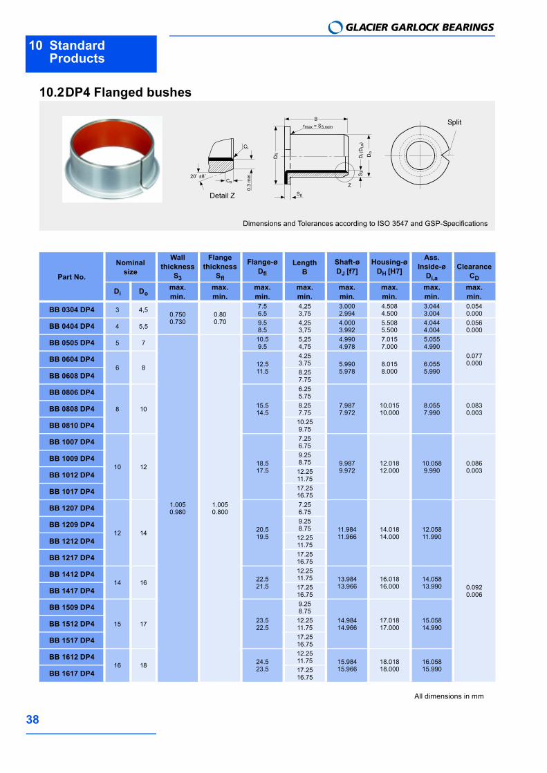
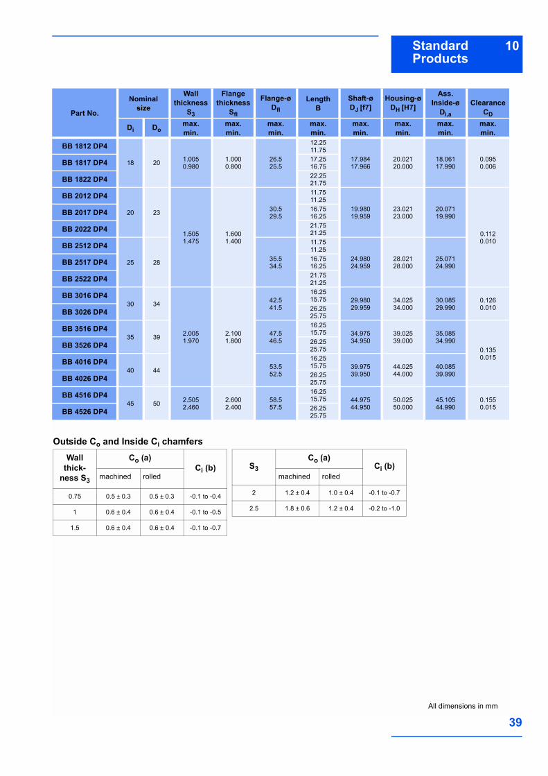
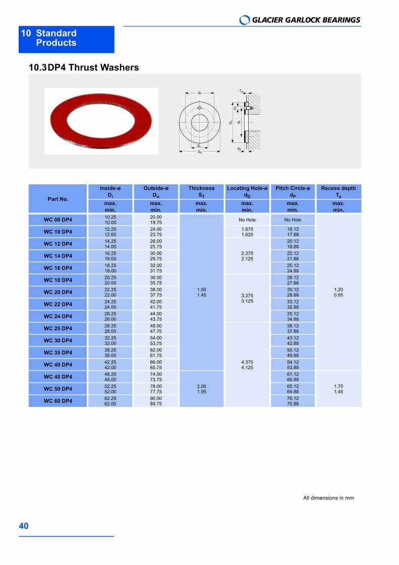
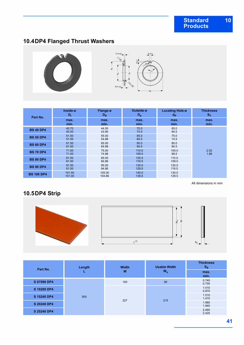
10 Standard Products . . . . 3310.1 DP4 Cylindrical bushes . . . . . . 3310.2 DP4 Flanged bushes . . . . . . . . 3810.3 DP4 Thrust Washers . . . . . . . . 4010.4 DP4 Flanged Thrust Washers . 4110.5 DP4 Strip . . . . . . . . . . . . . . . . . . 41
11 Test Methods . . . . . . . . . 4211.1 Measurement of
Wrapped Bushes . . . . . . . . . . . 42
1 IntroductionGLACIER GARLOCK BEARINGS
4
1 IntroductionDP4TM is a composite steel-backed poly-mer-lined bearing material. It wasdeveloped for high duty, oil lubricated,hydraulic applications as for example inautomotive suspension McPherson strutsand shock absorbers, hydraulic cylinders,gear pumps and motors and axial andradial piston pumps and motors. DP4 isdesigned for use mainly under lubricatedconditions and shows excellent wear resi-
stance, low static and dynamic frictioncoefficient and a high resistance to bothcavitation and flow erosion damage of thepolymer bearing surface by the lubricant.DP4 is suitable for sliding, oscillating, reci-procating and rotating applications.DP4 is also suitable for use with non-lubri-cating fluids and in light duty unlubricatedapplications.
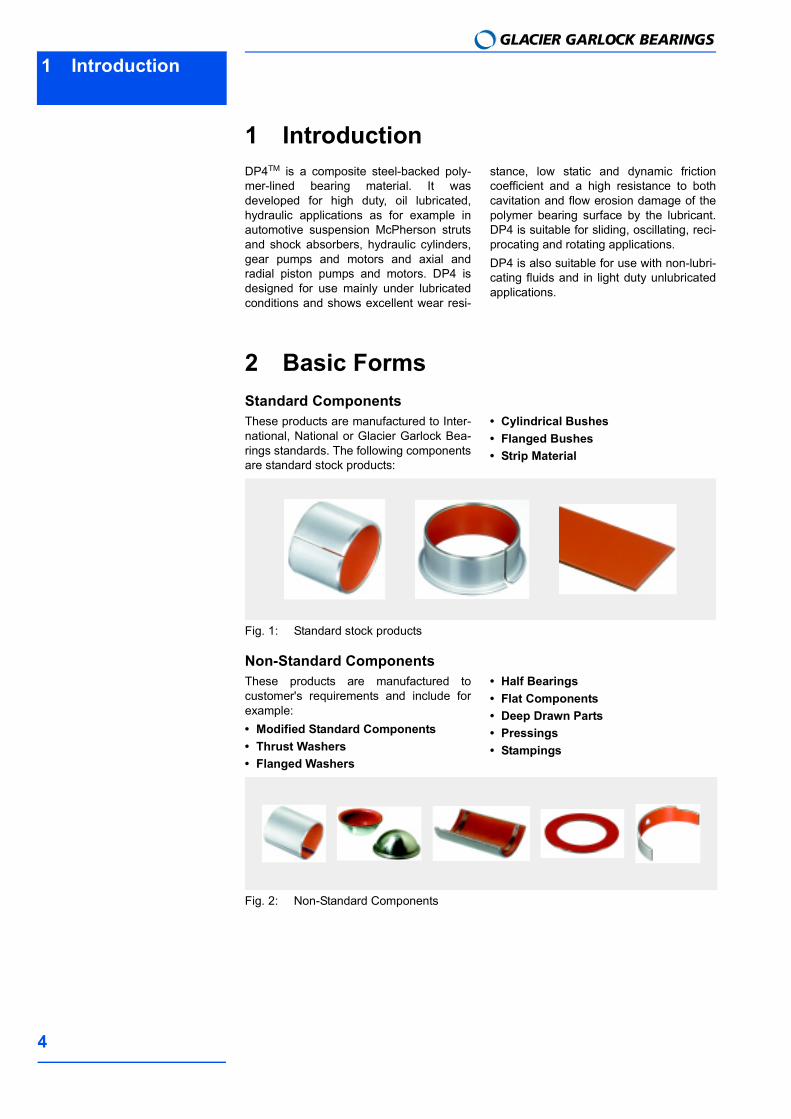
2 Basic FormsStandard ComponentsThese products are manufactured to Inter-national, National or Glacier Garlock Bea-rings standards. The following componentsare standard stock products:
Cylindrical Bushes Flanged Bushes Strip Material
Fig. 1: Standard stock products
Non-Standard ComponentsThese products are manufactured tocustomer's requirements and include forexample: Modified Standard Components Thrust Washers Flanged Washers
Half Bearings Flat Components Deep Drawn Parts Pressings Stampings
Fig. 2: Non-Standard Components

3Structure and Composition
5
3 Structure and CompositionDP4 consists of a steel backing to which isbonded a porous sinter bronze interlayerwhich is overlaid and impregnated withPolytetrafluoroethylene (PTFE) containinga mixture of inorganic fillers and specialpolymer fibres. The steel backing providesmechanical strength and the bronze sinterlayer provides a strong mechanical bondfor the filled bearing lining.
Fig. 3: DP4-microsection
4 Properties4.1 Physical and Mechanical Properties
Table 1: Physical and mechanical Properties of DP4
4.2 Chemical PropertiesThe following table provides an indicationof the chemical resistance of DP4 tovarious chemical media.
It is recommended, that the chemical resi-stance is confirmed by testing if possible.
Polytetrafluorethylene (PTFE) + fillers and po-lymer fibres
Bronze sinter layer
Steel backing
Symbol Value Unit CommentPhysical Properties
Coefficient of linear thermal expansion :
parallel to surface α1 11 1/106 K
normal to surface α2 30 1/106 KMaximum OperatingTemperature
Tmax +280 °C
Minimum OperatingTemperature
Tmin 200 °C
MechanicalProperties Compressive
Yield Strength σc 350 N/mm2measured on disc5 mm diameter x 2.45 mm thick.
Maximum Load
Static psta,max 250 N/mm2
Dynamic pdyn,max 140 N/mm2

4 PropertiesGLACIER GARLOCK BEARINGS
6
Table 2: Chemical resistance of DP4
4.3 Frictional PropertiesDP4 bearings show negligible 'stick-slip'and provide smooth sliding between adja-cent surfaces. The coefficient of friction ofDP4 depends upon: The specific load p [N/mm2] The sliding speed U [m/s] The roughness of the mating running
surface Ra [µm] The bearing temperature T [°C].A typical relationship is shown in Fig. 4,which can be used as a guide to establish
the actual friction under clean, dry conditi-ons after running in.Exact values may vary by ±20 % depen-ding on operating conditions. Before run-ning in, the friction may be up to 50 %higher.After progressively longer periods of dwellunder load (e.g. hours or days) the staticcoefficient of friction on the first movementmay be between 1.5 and 3 times greater,particularly before running in.
Chemical % °C RatingStrong Acids Hydrochloric Acid 5 20 -
Nitric Acid 5 20 -Sulphuric Acid 5 20 -
Weak Acids Acetic Acid 5 20 -Formic Acid 5 20 -
Bases Ammonia 10 20 oSodium Hydroxide 5 20 o
Solvents Acetone 20 +Carbon Tetrachloride 20 +
Lubricants and fuels Paraffin 20 +Gasolene 20 +Kerosene 20 +Diesel Fuel 20 +Mineral Oil 70 +HFA-ISO46 High Water Fluid 70 +HFC-Water-Glycol 70 +HFD-Phosphate Ester 70 +Water 20 oSea Water 20 -
+ Satisfactory: Corrosion damage is unlikely to occur.
oAcceptable: Some corrosion damage may occur but this will not be sufficient to impair either the structural integrity or the tribological performance of the material.
-Unsatisfactory: Corrosion damage will occur and is likely to affect either the structural integrity and/or the tribo-logical performance of the material.
4Properties
7
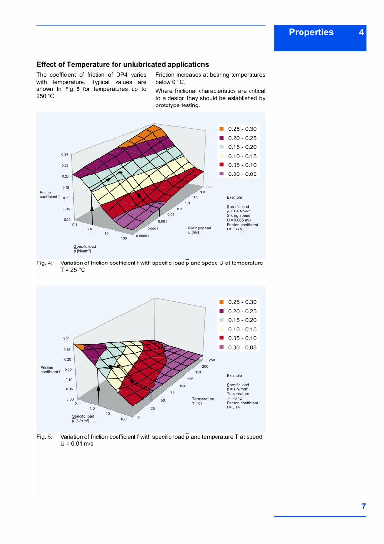
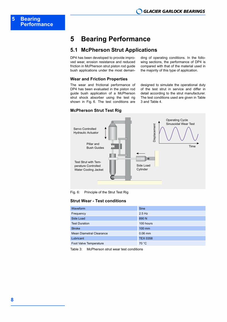
Effect of Temperature for unlubricated applicationsThe coefficient of friction of DP4 varieswith temperature. Typical values areshown in Fig. 5 for temperatures up to250 °C.
Friction increases at bearing temperaturesbelow 0 °C.Where frictional characteristics are criticalto a design they should be established byprototype testing.
Fig. 4: Variation of friction coefficient f with specific load p and speed U at temperatureT = 25 °C
Fig. 5: Variation of friction coefficient f with specific load p and temperature T at speedU = 0.01 m/s
Example
Specific loadp = 1.4 N/mm²Sliding speedU = 0.005 m/sFriction coefficientf = 0.175
0.25 - 0.30
0.20 - 0.25
0.15 - 0.20
0.10 - 0.15
0.05 - 0.10
0.00 - 0.05
0.30
0.25
0.20
0.15
0.10
0.05
0.000.1
1.010
1000.00001
0.0001
0.001
0.01
0.1
1.0
1.52.0
2.5
Sliding speedU [m/s]
Specific loadp [N/mm²]
Frictioncoefficient f
Example
Specific loadp = 4 N/mm²TemperatureT= 40 °CFriction coefficientf = 0.14
0.30
0.25
0.20
0.15
0.10
0.05
0.000.1
1.010
100 0
25
50
75
100
125
150
200
250
Specific loadp [N/mm²]
Friction coefficient f
TemperatureT [°C]
0.25 - 0.30
0.20 - 0.25
0.15 - 0.20
0.10 - 0.15
0.05 - 0.10
0.00 - 0.05
5 Bearing Performance
GLACIER GARLOCK BEARINGS
8
5 Bearing Performance5.1 McPherson Strut ApplicationsDP4 has been developed to provide impro-ved wear, erosion resistance and reducedfriction in McPherson strut piston rod guidebush applications under the most deman-
ding of operating conditions. In the follo-wing sections, the performance of DP4 iscompared with that of the material used inthe majority of this type of application.
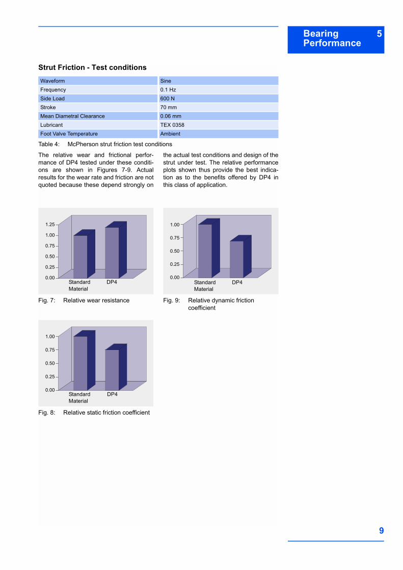
Wear and Friction PropertiesThe wear and frictional performance ofDP4 has been evaluated in the piston rodguide bush application of a McPhersonstrut shock absorber using the test rigshown in Fig. 6. The test conditions are
designed to simulate the operational dutyof the test strut in service and differ indetail according to the strut manufacturer.The test conditions used are given in Table3 and Table 4.
McPherson Strut Test Rig
Fig. 6: Principle of the Strut Test Rig
Strut Wear - Test conditions
Table 3: McPherson strut wear test conditions
Waveform SineFrequency 2.5 HzSide Load 890 NTest Duration 100 hoursStroke 100 mmMean Diametral Clearance 0.06 mmLubricant TEX 0358Foot Valve Temperature 70 °C
Servo Controlled Hydraulic Actuator
Pillar and Bush Guides
Test Strut with Tem-perature Controlled Water Cooling Jacket
Side Load Cylinder
Operating Cycle Sinusoidal Wear Test
Time
Dis
plac
emen
t
5Bearing Performance
9
Strut Friction - Test conditions
Table 4: McPherson strut friction test conditions
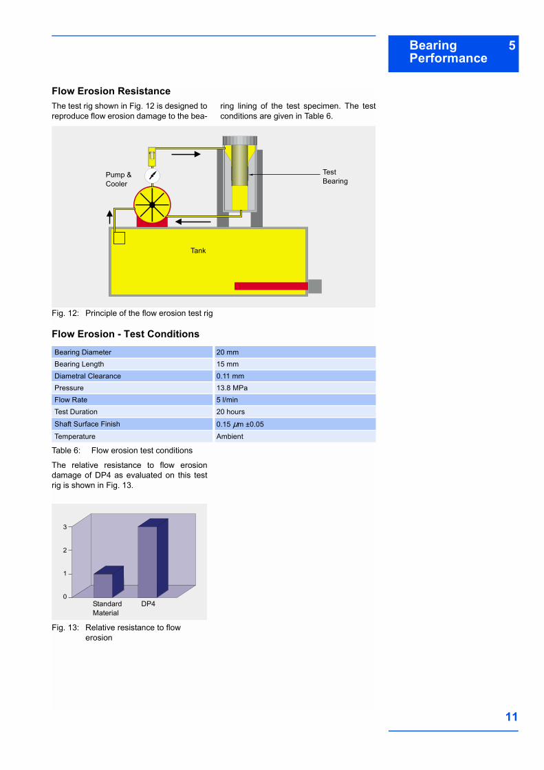
The relative wear and frictional perfor-mance of DP4 tested under these conditi-ons are shown in Figures 7-9. Actualresults for the wear rate and friction are notquoted because these depend strongly on
the actual test conditions and design of thestrut under test. The relative performanceplots shown thus provide the best indica-tion as to the benefits offered by DP4 inthis class of application.
Waveform SineFrequency 0.1 HzSide Load 600 NStroke 70 mmMean Diametral Clearance 0.06 mmLubricant TEX 0358Foot Valve Temperature Ambient
Fig. 7: Relative wear resistance
Fig. 8: Relative static friction coefficient
1.25
1.00
0.75
0.50
0.25
0.00Standard Material
DP4
1.00
0.75
0.50
0.25
0.00Standard Material
DP4
Fig. 9: Relative dynamic frictioncoefficient
1.00
0.75
0.50
0.25
0.00Standard Material
DP4

5 Bearing Performance
GLACIER GARLOCK BEARINGS
10
Cavitation Erosion ResistanceUnder certain operating conditions, thePTFE lining of the McPherson strut pistonrod guide bush can suffer erosion damage,due to cavitation and flow erosion effectsfrom the oil film within the bearing. The test
rig shown in Fig. 10 is designed to repro-duce the cavitation erosion damage to thebearing lining of the test specimen. Thetest conditions are given in Table 5.
Fig. 10: Principle of the cavitation erosion test rig
Cavitation Erosion - Test Conditions
Table 5: Cavitation erosion test conditions
The relative resistance to cavitationdamage of DP4 as evaluated on this testrig is shown in Fig. 11.
Fig. 11: Relative resistance to cavitation erosion
Amplitude 0.015 mmFrequency 20 kHzSeparation 1 mmTest Duration 30 minutesLubricant TEX 0358Temperature Ambient
Clamps
Horn vibration produ-ces vapour bubbles in gap, which implode on the surface of the sam-ple, causing cavitation erosion damage
Saddle
Test Cell or Pot
Flat Test Specimen
Coupling Media (Oil)
Vibrating Amplifying Horn
20 kHz Piezo-Electric Transducer
5
4
3
2
1
0Standard Material
DP4
5Bearing Performance
11
Flow Erosion ResistanceThe test rig shown in Fig. 12 is designed toreproduce flow erosion damage to the bea-
ring lining of the test specimen. The testconditions are given in Table 6.
Fig. 12: Principle of the flow erosion test rig
Flow Erosion - Test Conditions
Table 6: Flow erosion test conditions
The relative resistance to flow erosiondamage of DP4 as evaluated on this testrig is shown in Fig. 13.
Fig. 13: Relative resistance to flowerosion
Bearing Diameter 20 mmBearing Length 15 mmDiametral Clearance 0.11 mmPressure 13.8 MPaFlow Rate 5 l/minTest Duration 20 hoursShaft Surface Finish 0.15 µm ±0.05Temperature Ambient
Pump & Cooler
Tank
Test Bearing
3
2
1
0Standard Material
DP4
5 Bearing Performance
GLACIER GARLOCK BEARINGS
12
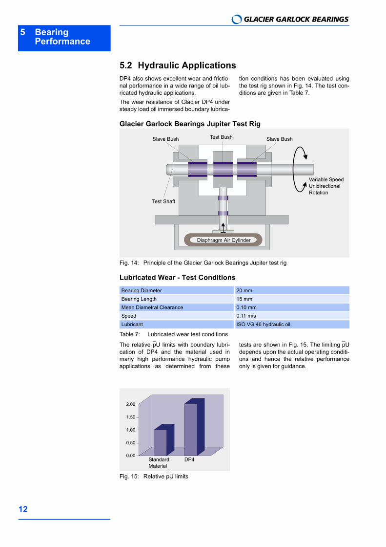
5.2 Hydraulic ApplicationsDP4 also shows excellent wear and frictio-nal performance in a wide range of oil lub-ricated hydraulic applications. The wear resistance of Glacier DP4 understeady load oil immersed boundary lubrica-
tion conditions has been evaluated usingthe test rig shown in Fig. 14. The test con-ditions are given in Table 7.
Glacier Garlock Bearings Jupiter Test Rig
Fig. 14: Principle of the Glacier Garlock Bearings Jupiter test rig
Lubricated Wear - Test Conditions
Table 7: Lubricated wear test conditions
The relative pU limits with boundary lubri-cation of DP4 and the material used inmany high performance hydraulic pumpapplications as determined from these
tests are shown in Fig. 15. The limiting pUdepends upon the actual operating conditi-ons and hence the relative performanceonly is given for guidance.
Fig. 15: Relative pU limits
Bearing Diameter 20 mmBearing Length 15 mmMean Diametral Clearance 0.10 mmSpeed 0.11 m/sLubricant ISO VG 46 hydraulic oil
Test BushSlave Bush
Test Shaft
Diaphragm Air Cylinder
Variable Speed Unidirectional Rotation
Slave Bush
2.00
1.50
1.00
0.50
0.00Standard Material
DP4
5Bearing Performance
13
5.3 Dry Wear Performance
Design FactorsThe main parameters when determiningthe size or calculating the service life for aDP4 bearing are: Specific Load Limit plim pU Factor
Mating surface roughness Ra
Mating surface material Temperature T
Other environmental factors e.g. hou-sing design, dirt, lubrication
The following calculation can be used toestimate the bearing service life of DP4under dry running conditions.
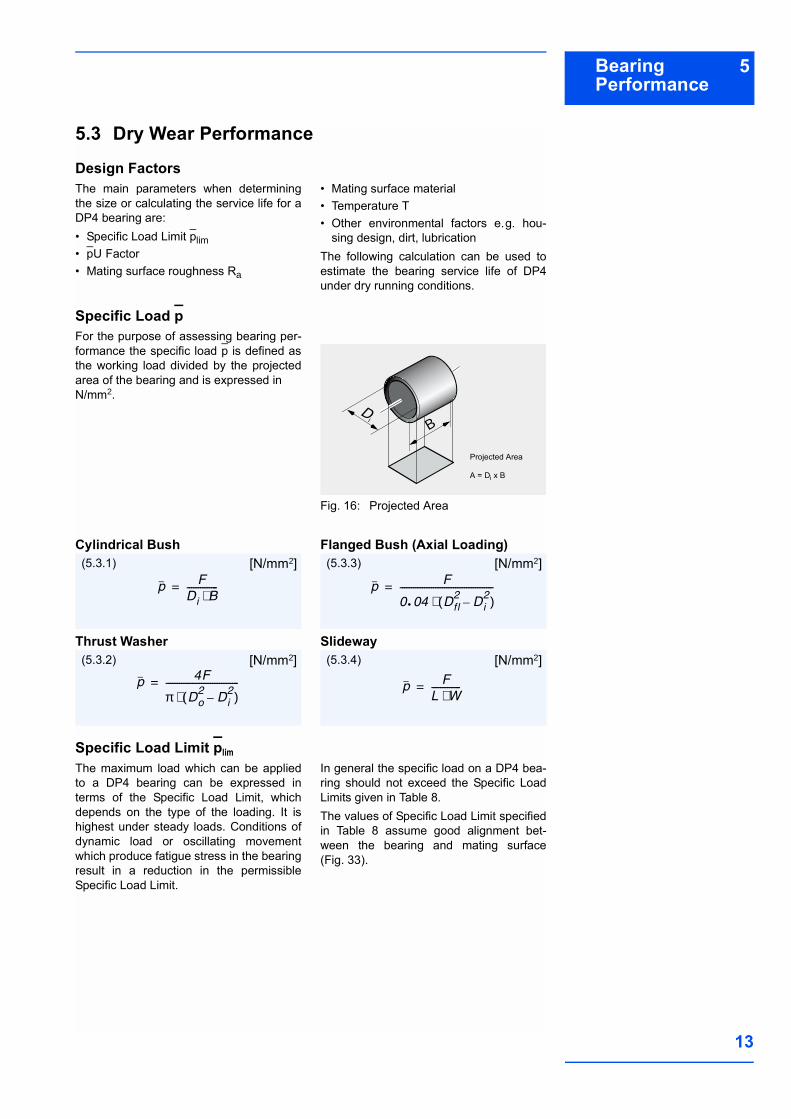
Specific Load p For the purpose of assessing bearing per-formance the specific load p is defined asthe working load divided by the projectedarea of the bearing and is expressed inN/mm2.
Fig. 16: Projected Area
Cylindrical Bush
Thrust Washer
Flanged Bush (Axial Loading)
Slideway
Specific Load Limit plim The maximum load which can be appliedto a DP4 bearing can be expressed interms of the Specific Load Limit, whichdepends on the type of the loading. It ishighest under steady loads. Conditions ofdynamic load or oscillating movementwhich produce fatigue stress in the bearingresult in a reduction in the permissibleSpecific Load Limit.
In general the specific load on a DP4 bea-ring should not exceed the Specific LoadLimits given in Table 8.The values of Specific Load Limit specifiedin Table 8 assume good alignment bet-ween the bearing and mating surface(Fig. 33).
BD
i
Projected Area
A = Di x B
p FDi B⋅--------------=
(5.3.1) [N/mm2]
p 4F
π Do2Di2
( )⋅---------------------------------=
(5.3.2) [N/mm2]
p F
0 04, Dfl2Di2
( )⋅------------------------------------------=
(5.3.3) [N/mm2]
p FL W⋅-------------=
(5.3.4) [N/mm2]
5 Bearing Performance
GLACIER GARLOCK BEARINGS
14
Maximum specific load plim
Table 8: Specific load limit
Permanent deformation of the DP4 bea-ring lining may occur at specific loadsabove 140 N/mm2. Under these conditionsDP4 should only be used after consultingour application engineers or with slowintermittent movements.
The permissible maximum load on a thrustwasher is higher than that on the flange ofa flanged bush, and under conditions ofhigh axial loads a thrust washer should bespecified.
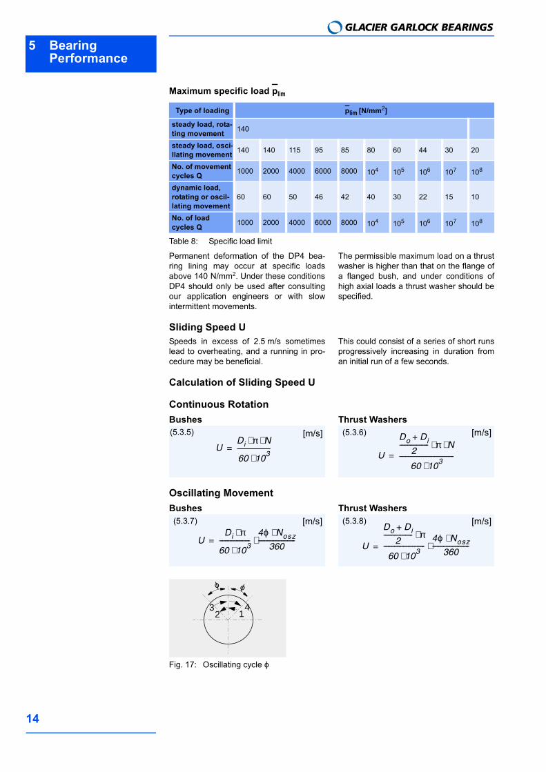
Sliding Speed USpeeds in excess of 2.5 m/s sometimeslead to overheating, and a running in pro-cedure may be beneficial.
This could consist of a series of short runsprogressively increasing in duration froman initial run of a few seconds.
Calculation of Sliding Speed U
Continuous RotationBushes Thrust Washers
Oscillating MovementBushes Thrust Washers
Fig. 17: Oscillating cycle ϕ
Type of loading plim [N/mm2]
steady load, rota-ting movement 140
steady load, osci-llating movement 140 140 115 95 85 80 60 44 30 20
No. of movement cycles Q 1000 2000 4000 6000 8000 104 105 106 107 108
dynamic load, rotating or oscil-lating movement
60 60 50 46 42 40 30 22 15 10
No. of loadcycles Q 1000 2000 4000 6000 8000 104 105 106 107 108
UDi π N⋅ ⋅
60 103⋅
----------------------=
(5.3.5) [m/s]
U
Do Di+
2------------------- π N⋅ ⋅
60 103⋅
------------------------------------=
(5.3.6) [m/s]
UDi π⋅
60 103⋅
--------------------4ϕ Nosz⋅360
------------------------⋅=
(5.3.7) [m/s]
U
Do Di+
2------------------- π⋅
60 103⋅
---------------------------4ϕ Nosz⋅360
------------------------⋅=
(5.3.8) [m/s]
ϕ ϕ
123 4
5Bearing Performance
15
pU FactorThe useful operating life of a DP4 bearingis governed by the pU factor, the product ofthe specific load p [N/mm2] and the slidingspeed U [m/s].For thrust washers and flanged bush thrustfaces the rubbing velocity at the mean dia-meter is used.
Table 9: Typical data p, U, pU
pU factors up to 1.0 N/mm2 x m/s can beaccommodated for short periods, whilst forcontinuous rating, pU factors up to 0.5 N/mm2 x m/s can be used, depending uponthe operating life required.
Calculation of pU Factor
Application FactorsThe following factors influence the bearingperformance of DP4 and must be conside-red in calculating the required dimensions
or estimating the bearing life for a particu-lar application.
Temperature The useful life of a DP4 bearing dependsupon the operating temperature.Under dry running conditions frictional heatis generated at the rubbing surface of thebearing dependent on the pU condition.For a given pU factor the operating tempe-rature of the bearing depends upon thetemperature of the surrounding environ-
ment, the heat dissipation properties of thehousing and the mating surface. Intermit-tent operation affects the heat dissipationfrom the assembly and hence the opera-ting temperature of the bearing.The effect of temperature on the operatinglife of DP4 bearings is indicated by the fac-tor aT shown in Table 10.
Table 10: Temperature application factor aT
DP4 Unitp 140 N/mm²U 2.5 m/spU continuous 0.5 N/mm² x m/spU intermittent 1.0 N/mm² x m/s
pU p U⋅=
(5.3.9) [N/mm2 x m/s]
Mode of Operation Nature of housingTemperature of bearing environment Tamb [°C]
and Temperature application factor aT
25 60 100 150 200 280Dry continuous operation Average heat dissipating qualities 1.0 0.8 0.6 0.4 0.2 0.1Dry continuous operation Light pressings or isolated housing
with poor heat dissipating qualities 0.5 0.4 0.3 0.2 0.1 -
Dry continuous operation Non-metallic housings with bad heat dissipating qualities 0.3 0.3 0.2 0.1 - -
Dry intermittent operation (duration less than 2 min, followed by a longer dwell period)
Average heat dissipating qualities 2.0 1.6 1.2 0.8 0.4 0.2
5 Bearing Performance
GLACIER GARLOCK BEARINGS
16
Mating SurfaceThe effect of mating surface material typeon the operating life of DP4 bearings isindicated by the mating surface factor aMand life correction constant aL shown inTable 11.
Note:The factor values given assume a matingsurface finish of ≤0.4 µm Ra.
A ground surface is preferred to fine tur-ned.
Surfaces should be cleaned of abrasiveparticles after polishing.
Cast iron surfaces should be ground to<0.3 µm Ra.
The grinding cut should be in the samedirection as the bearing motion relativeto the shaft.
Table 11: Mating surface factor aM and life correction constant aL
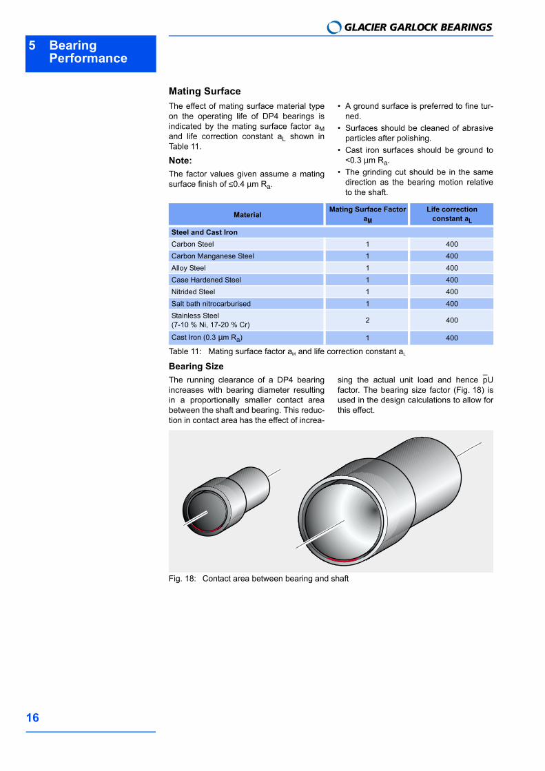
Bearing SizeThe running clearance of a DP4 bearingincreases with bearing diameter resultingin a proportionally smaller contact areabetween the shaft and bearing. This reduc-tion in contact area has the effect of increa-
sing the actual unit load and hence pUfactor. The bearing size factor (Fig. 18) isused in the design calculations to allow forthis effect.
Fig. 18: Contact area between bearing and shaft
MaterialMating Surface Factor
aM
Life correction constant aL
Steel and Cast IronCarbon Steel 1 400Carbon Manganese Steel 1 400Alloy Steel 1 400Case Hardened Steel 1 400Nitrided Steel 1 400Salt bath nitrocarburised 1 400Stainless Steel(7-10 % Ni, 17-20 % Cr) 2 400
Cast Iron (0.3 µm Ra) 1 400
5Bearing Performance
17
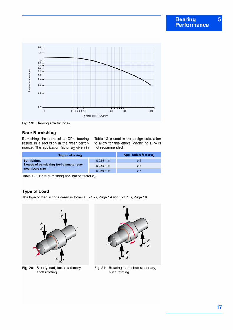
Fig. 19: Bearing size factor aB
Bore BurnishingBurnishing the bore of a DP4 bearingresults in a reduction in the wear perfor-mance. The application factor aC given in
Table 12 is used in the design calculationto allow for this effect. Machining DP4 isnot recommended.
Table 12: Bore burnishing application factor aC
Type of LoadThe type of load is considered in formula (5.4.9), Page 19 and (5.4.10), Page 19.
Fig. 20: Steady load, bush stationary, shaft rotating
Fig. 21: Rotating load, shaft stationary, bush rotating
Bear
ing
size
fact
or a
B
Shaft diameter DJ [mm]
0.2
0.3
1.0
1
0.5
0.1
0.4
5
0.60.7
0.90.8
2.0
6 7 8 9 10 50 100 500
1.5
Degree of sizing Application factor aC
Burnishing:Excess of burnishing tool diameter over mean bore size
0.025 mm 0.80.038 mm 0.60.050 mm 0.3
F2---
F2---
F
F2---
F2---
F
5 Bearing Performance
GLACIER GARLOCK BEARINGS
18
5.4 Calculation of Bearing Service LifeWhere the size of a bearing is governedlargely by the space available the followingcalculation can be used to determine whe-
ther its useful life will satisfy the require-ments. If the calculated life is inadequate,a redesign should be considered.
Specific load pBushes
Flanged Bushes
Thrust Washers
High load factor aE
If aE is negative then the bearing is over-loaded. Increase the bearing diameterand/or length.
Modified pU Factor Bushes Flanged Bushes
Thrust Washers For oscillating movement, calculate theaverage rotational speed.
Estimation of bearing life LH Bushes (Steady load) Bushes (Rotating load)
(5.4.1) [N/mm2]
p FDi B⋅--------------=
(5.4.2) [N/mm2]
p F
0 04, Dfl2Di2
( )⋅-------------------------------------------=
(5.4.3) [N/mm2]
p 4F
p Do2Di2
( )⋅---------------------------------=
aEplim p
plim-----------------=
(5.4.4) []
plim see Tab. 8, page 14
pU 5 25 105⋅, F N⋅
aE B aT aM aB⋅⋅ ⋅ ⋅-------------------------------------------------=
(5.4.5) [N/mm2 x m/s]
pU 6 5 104⋅, F N⋅
aE Dfl Di( ) aT aM aB⋅⋅ ⋅ ⋅---------------------------------------------------------------------=
(5.4.6) [N/mm2 x m/s]
pU 3 34 105⋅, F N⋅
aE Do Di( ) aT aM aB⋅⋅ ⋅ ⋅---------------------------------------------------------------------=
(5.4.7) [N/mm2 x m/s]
NE
4ϕ Nosz⋅360
------------------------=
(5.4.8) [1/min]
LH265pU---------- aL=
(5.4.9) [h]
LH530pU---------- aL=
(5.4.10) [h]
5Bearing Performance
19
Flanged Bushes (Axial load) Thrust Washers
Bore BurnishingIf the DP4 bush is bore burnished then thismust be allowed for in estimating the bea-ring life by the application factor aC (Table12, Page 18).
Estimated Bearing Life
For Oscillating Movements or Dynamic loadsCalculate estimated number of cycles ZT If the required bearing life is known, the
total number of cycles can be determined.Check that ZT is less than total number ofcycles Q for the operating specific load plim
(Table 8, Page 15).If ZT <Q, bearing life will be limited by wearafter ZT cycles.If ZT >Q, bearing life will be limited by fati-gue after ZT cycles.
SlidewaysSpecific load factor
If negative the bearing is overloaded andthe bearing area should be increased.
Speed, temperature and material application factor
Relative contact area factor
Estimated bearing life Note:Estimated bearing lives greater than 4000hours are subject to error due to inaccura-cies in the extrapolation of test data.
LH175pU---------- aL=
(5.4.11) [h]
aL see Table 11, Page 17
LH175pU---------- aL=
(5.4.12) [h]
LH LH aC⋅=
(5.4.13) [h]
aC see Table 12, Page 18
ZT LH Nosz 60⋅ ⋅=
(5.4.14) [cycles]
ZT LH C 60⋅ ⋅=
(5.4.15) [cycles]
aE1 A Fplim----------=
(5.4.16) []
aE2280 aT aM⋅ ⋅
F U⋅---------------------------------=
(5.4.17) []
aT see Table 10, Page 16aM see Table 11, Page 17
aE3AAM--------=
(5.4.18) []
LH aE1 aE2 aE3 aL⋅ ⋅=
(5.4.19) []
5 Bearing Performance
GLACIER GARLOCK BEARINGS
20
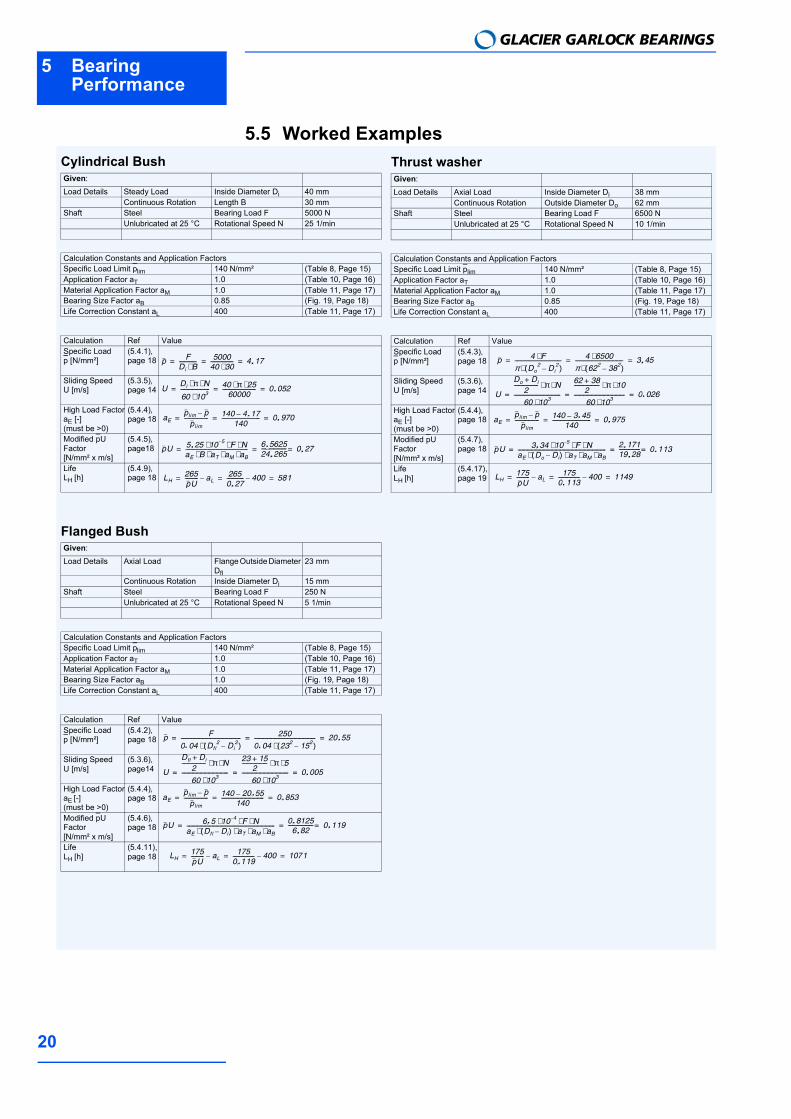
5.5 Worked ExamplesCylindrical BushGiven:Load Details Steady Load Inside Diameter Di 40 mm
Continuous Rotation Length B 30 mmShaft Steel Bearing Load F 5000 N
Unlubricated at 25 °C Rotational Speed N 25 1/min
Calculation Constants and Application FactorsSpecific Load Limit plim 140 N/mm² (Table 8, Page 15)Application Factor aT 1.0 (Table 10, Page 16)Material Application Factor aM 1.0 (Table 11, Page 17)Bearing Size Factor aB 0.85 (Fig. 19, Page 18)Life Correction Constant aL 400 (Table 11, Page 17)
Calculation Ref ValueSpecific Load p [N/mm²]
(5.4.1), page 18
Sliding Speed U [m/s]
(5.3.5), page 14
High Load FactoraE [-] (must be >0)
(5.4.4), page 18
Modified pUFactor[N/mm² x m/s]
(5.4.5), page18
LifeLH [h]
(5.4.9), page 18
p FDi B⋅------------- 5000
40 30⋅----------------- 4 17,= = = .
UDi π N⋅ ⋅
60 103⋅---------------------- 40 π 25⋅ ⋅
60000------------------------- 0 052,= = = .
aEplim pplim------------------ 140 4 17,
140----------------------------- 0 970,= = =. .
pU 5 25, 10 5 F N⋅ ⋅ ⋅aE B aT aM aB⋅ ⋅ ⋅ ⋅----------------------------------------------- 6 5625,
24 265,------------------- 0 27,== = .
.. .
LH265pU---------- aL 265
0 27,------------- 400 581= = =
.
Flanged BushGiven:Load Details Axial Load Flange Outside Diameter
Dfl
23 mm
Continuous Rotation Inside Diameter Di 15 mmShaft Steel Bearing Load F 250 N
Unlubricated at 25 °C Rotational Speed N 5 1/min
Calculation Constants and Application FactorsSpecific Load Limit plim 140 N/mm² (Table 8, Page 15)Application Factor aT 1.0 (Table 10, Page 16)Material Application Factor aM 1.0 (Table 11, Page 17)Bearing Size Factor aB 1.0 (Fig. 19, Page 18)Life Correction Constant aL 400 (Table 11, Page 17)
Calculation Ref ValueSpecific Load p [N/mm²]
(5.4.2), page 18
Sliding Speed U [m/s]
(5.3.6), page14
High Load FactoraE [-](must be >0)
(5.4.4), page 18
Modified pUFactor[N/mm² x m/s]
(5.4.6), page 18
LifeLH [h]
(5.4.11), page 18
p F
0 04, Dfl2 Di
2( )⋅--------------------------------------------- 250
0 04, 232 152( )⋅---------------------------------------------- 20 55,= = = .
. .
U
Dfl Di+2
------------------ π N⋅ ⋅
60 103⋅-----------------------------------
23 15+2
------------------- π 5⋅ ⋅
60 103⋅----------------------------------- 0 005,= = = .
aEplim pplim
------------------ 140 20 55,140
-------------------------------- 0 853,= = =. .
pU 6 5, 10 4 F N⋅ ⋅ ⋅aE Dfl Di( ) aT aM aB⋅ ⋅ ⋅ ⋅------------------------------------------------------------------ 0 8125,
6 82,------------------- 0 119,== = ..
..
LH175pU---------- aL 175
0 119,---------------- 400 1071= = =
.
Thrust washerGiven:Load Details Axial Load Inside Diameter Di 38 mm
Continuous Rotation Outside Diameter Do 62 mmShaft Steel Bearing Load F 6500 N
Unlubricated at 25 °C Rotational Speed N 10 1/min
Calculation Constants and Application FactorsSpecific Load Limit plim 140 N/mm² (Table 8, Page 15)Application Factor aT 1.0 (Table 10, Page 16)Material Application Factor aM 1.0 (Table 11, Page 17)Bearing Size Factor aB 0.85 (Fig. 19, Page 18)Life Correction Constant aL 400 (Table 11, Page 17)
Calculation Ref ValueSpecific Load p [N/mm²]
(5.4.3), page 18
Sliding Speed U [m/s]
(5.3.6), page 14
High Load FactoraE [-](must be >0)
(5.4.4), page 18
Modified pUFactor[N/mm² x m/s]
(5.4.7), page 18
LifeLH [h]
(5.4.17), page 19
p 4 F⋅π Do
2 Di2( )⋅
----------------------------------- 4 6500⋅π 622 382( )⋅------------------------------------ 3 45,= = = .
U
Do Di+2
------------------ π N⋅ ⋅
60 103⋅-----------------------------------
62 38+2
------------------- π 10⋅ ⋅
60 103⋅-------------------------------------- 0 026,= = = .
aEplim pplim
------------------ 140 3 45,140
----------------------------- 0 975,= = =. .
pU 3 34 10 5 F N⋅ ⋅ ⋅,aE Do Di( ) aT aM aB⋅ ⋅ ⋅ ⋅------------------------------------------------------------------ 2 171,
19 28,---------------- 0 113,== = .
. ..
LH175pU---------- aL 175
0 113,---------------- 400 1149= = =
.
6Data Sheet
21
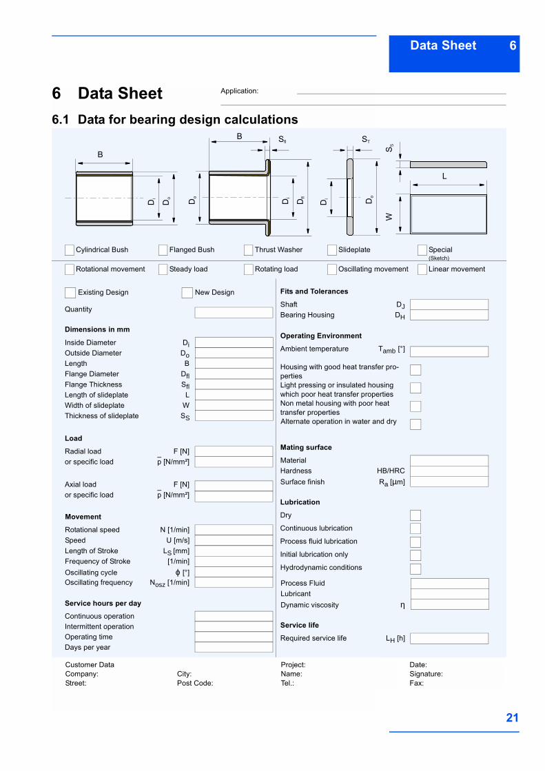
6 Data Sheet6.1 Data for bearing design calculations
Quantity
Dimensions in mm
Inside Diameter Di
Length BOutside Diameter Do
Flange Diameter DflFlange Thickness SflLength of slideplate LWidth of slideplate WThickness of slideplate SS
Radial load F [N]or specific load p [N/mm²]
Axial load F [N]or specific load p [N/mm²]
Oscillating frequency Nosz [1/min]
Rotational speed N [1/min]Speed U [m/s]Length of Stroke LS [mm]Frequency of Stroke [1/min]Oscillating cycle ϕ [°]
Continuous operation
Load
Service hours per day
Days per yearOperating timeIntermittent operation
Movement
Shaft DJBearing Housing DH
Fits and Tolerances
Ambient temperature Tamb [°]
Operating Environment
Non metal housing with poor heat transfer properties
Light pressing or insulated housing which poor heat transfer properties
Housing with good heat transfer pro-perties
Material
Mating surface
Surface finish Ra [µm]Hardness HB/HRC
Process FluidLubricant
Alternate operation in water and dry
Dry
Lubrication
Process fluid lubrication
Continuous lubrication
Initial lubrication only
Hydrodynamic conditions
Dynamic viscosity η
Required service life LH [h]
Service life
Rotational movement Steady load Rotating load Oscillating movement
Cylindrical Bush Flanged Bush Thrust Washer Slideplate
Existing Design New Design
Special(Sketch)
Linear movement
BD
i
Do Di
Dfl
DiDo Do
WS S
B Sfl ST
L
Customer DataCompany:Street:
Project:Name:Tel.:
Date:Signature:Fax:
City:Post Code:
Application:

7 LubricationGLACIER GARLOCK BEARINGS
22
7 LubricationDP4 provides excellent performance inlubricated applications. The following sec-tions describe the basics of lubrication and
provide guidance on the application of DP4in such environments.
7.1 LubricantsDP4 can be used with most fluids inclu-ding: water lubricating oils engine oil turbine oil hydraulic fluid solvent refrigerantsIn general, the fluid will be acceptable if itdoes not chemically attack the filled PTFEoverlay or the porous bronze interlayer.
Where there is doubt about the suitabilityof a fluid, a simple test is to submerge asample of DP4 material in the fluid for twoto three weeks at 15-20 °C above the ope-rating temperature. The following will usually indicate that thefluid is not suitable for use with DP4: A significant change in the thickness of
the DP4 material, A visible change in the bearing surface
other than some discolouration or stai-ning,
A visible change in the microstructure ofthe bronze interlayer.
7.2 TribologyThere are three modes of lubricated bea-ring operation which relate to the thicknessof the developed lubricant film between thebearing and the mating surface: Hydrodynamic lubrication Mixed film lubrication Boundary lubrication.
These three modes of operation dependupon: Bearing dimensions Clearance Load Speed Lubricant Viscosity Lubricant Flow
Hydrodynamic lubrication Characterised by: Complete separation of the shaft from
the bearing by the lubricant film Very low friction and no wear of the bea-
ring or shaft since there is no contact Coefficients of friction of 0.001 to 0.01
Hydrodynamic conditions occur when
Fig. 22: Hydrodynamic lubrication
pU η⋅7 5,------------ B
Di-----⋅≤
(7.2.1) [N/mm2]
.
7Lubrication
23
Mixed film lubricationCharacterised by: Combination of hydrodynamic and
boundary lubrication. Part of the load is carried by localised
areas of self pressurised lubricant andthe remainder supported by boundarylubrication.
Friction and wear depend upon thedegree of hydrodynamic supportdeveloped.
DP4 provides low friction and high wearresistance to support the boundary lubri-cated element of the load.
Fig. 23: Mixed film lubrication
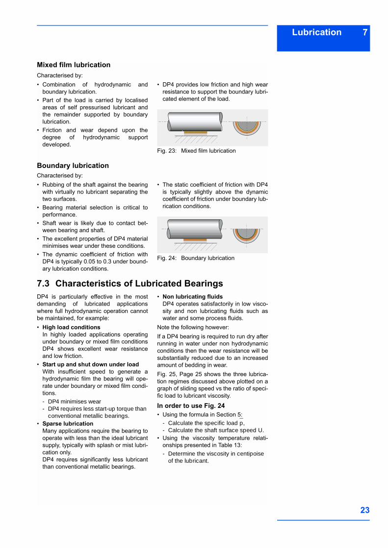
Boundary lubrication Characterised by: Rubbing of the shaft against the bearing
with virtually no lubricant separating thetwo surfaces.
Bearing material selection is critical toperformance.
Shaft wear is likely due to contact bet-ween bearing and shaft.
The excellent properties of DP4 materialminimises wear under these conditions.
The dynamic coefficient of friction withDP4 is typically 0.05 to 0.3 under bound-ary lubrication conditions.
The static coefficient of friction with DP4is typically slightly above the dynamiccoefficient of friction under boundary lub-rication conditions.
Fig. 24: Boundary lubrication
7.3 Characteristics of Lubricated BearingsDP4 is particularly effective in the mostdemanding of lubricated applicationswhere full hydrodynamic operation cannotbe maintained, for example: High load conditions
In highly loaded applications operatingunder boundary or mixed film conditionsDP4 shows excellent wear resistanceand low friction.
Start up and shut down under load With insufficient speed to generate ahydrodynamic film the bearing will ope-rate under boundary or mixed film condi-tions.- DP4 minimises wear- DP4 requires less start-up torque than
conventional metallic bearings. Sparse lubrication
Many applications require the bearing tooperate with less than the ideal lubricantsupply, typically with splash or mist lubri-cation only.DP4 requires significantly less lubricantthan conventional metallic bearings.
Non lubricating fluids DP4 operates satisfactorily in low visco-sity and non lubricating fluids such aswater and some process fluids.
Note the following however:If a DP4 bearing is required to run dry afterrunning in water under non hydrodynamicconditions then the wear resistance will besubstantially reduced due to an increasedamount of bedding in wear.Fig. 25, Page 25 shows the three lubrica-tion regimes discussed above plotted on agraph of sliding speed vs the ratio of speci-fic load to lubricant viscosity.
In order to use Fig. 24 Using the formula in Section 5:
- Calculate the specific load p,- Calculate the shaft surface speed U.
Using the viscosity temperature relati-onships presented in Table 13:- Determine the viscosity in centipoise
of the lubricant.
7 LubricationGLACIER GARLOCK BEARINGS
24
Note:Viscosity is a function of operating tempe-rature. If the operating temperature of the
fluid is unknown, a provisional temperatureof 25 °C above ambient can be used.
7.4 Design Guidance
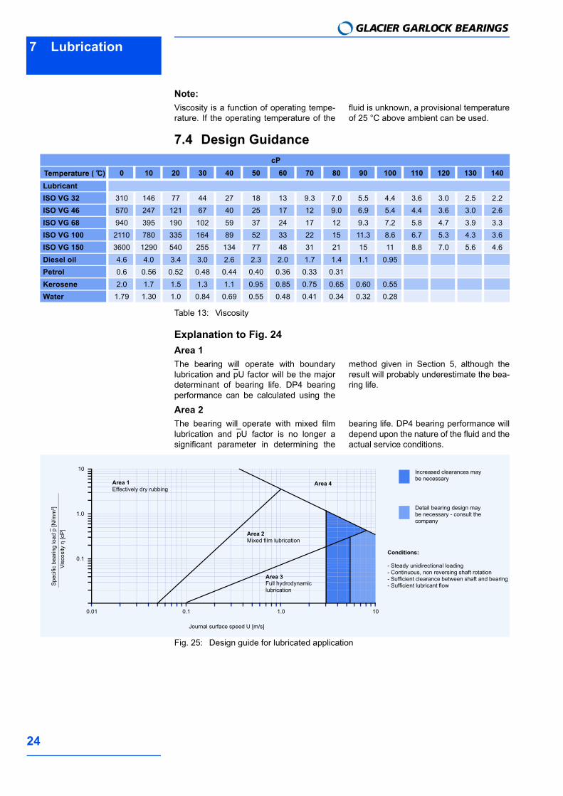
Table 13: Viscosity
Explanation to Fig. 24Area 1The bearing will operate with boundarylubrication and pU factor will be the majordeterminant of bearing life. DP4 bearingperformance can be calculated using the
method given in Section 5, although theresult will probably underestimate the bea-ring life.
Area 2The bearing will operate with mixed filmlubrication and pU factor is no longer asignificant parameter in determining the
bearing life. DP4 bearing performance willdepend upon the nature of the fluid and theactual service conditions.
Fig. 25: Design guide for lubricated application
cPTemperature (°C) 0 10 20 30 40 50 60 70 80 90 100 110 120 130 140LubricantISO VG 32 310 146 77 44 27 18 13 9.3 7.0 5.5 4.4 3.6 3.0 2.5 2.2ISO VG 46 570 247 121 67 40 25 17 12 9.0 6.9 5.4 4.4 3.6 3.0 2.6ISO VG 68 940 395 190 102 59 37 24 17 12 9.3 7.2 5.8 4.7 3.9 3.3ISO VG 100 2110 780 335 164 89 52 33 22 15 11.3 8.6 6.7 5.3 4.3 3.6ISO VG 150 3600 1290 540 255 134 77 48 31 21 15 11 8.8 7.0 5.6 4.6Diesel oil 4.6 4.0 3.4 3.0 2.6 2.3 2.0 1.7 1.4 1.1 0.95Petrol 0.6 0.56 0.52 0.48 0.44 0.40 0.36 0.33 0.31Kerosene 2.0 1.7 1.5 1.3 1.1 0.95 0.85 0.75 0.65 0.60 0.55Water 1.79 1.30 1.0 0.84 0.69 0.55 0.48 0.41 0.34 0.32 0.28
Spec
ific
bear
ing
load
p [N
/mm
²]
Journal surface speed U [m/s]
0.1
1.0
10
0.01 0.1 1.0 10
Increased clearances may be necessary
Detail bearing design may be necessary - consult the company
Area 1Effectively dry rubbing
Area 2Mixed film lubrication
Area 3Full hydrodynamic lubrication
Area 4
Visc
osity
η [c
P]
Conditions:
- Steady unidirectional loading- Continuous, non reversing shaft rotation- Sufficient clearance between shaft and bearing- Sufficient lubricant flow
7Lubrication
25
Area 3The bearing will operate with hydrodyna-mic lubrication. Bearing wear will be deter-mined only by the cleanliness of the
lubricant and the frequency of start up andshut down.
Area 4These are the most demanding operatingconditions. The bearing is operated undereither high speed or high bearing load toviscosity ratio, or, a combination of both. These conditions may cause excessive operating temperature and/or high wear rate.
Bearing performance may be improved bythe addition of one or more grooves to thebearing and a shaft surface finish <0.05µm Ra.
7.5 Clearances for lubricated operationThe recommended shaft and housing dia-meters given for standard DP4 bushes willprovide sufficient clearance for applicati-ons operating with boundary lubrication.For bearings operating with mixed film orhydrodynamic lubrication it may be neces-
sary to improve the fluid flow through thebearing by reducing the recommendedshaft diameter by approximately 0.1 %,particularly when the shaft surface speedexceeds 2.5 m/s.
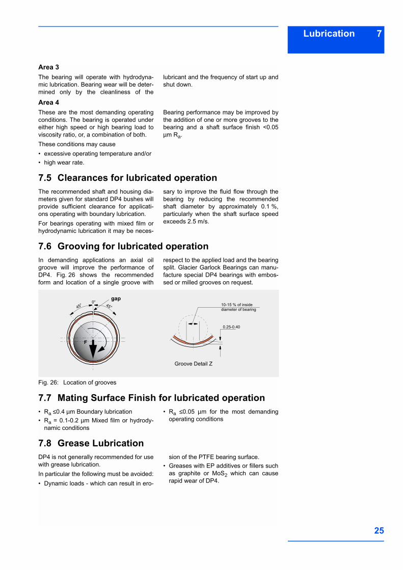
7.6 Grooving for lubricated operationIn demanding applications an axial oilgroove will improve the performance ofDP4. Fig. 26 shows the recommendedform and location of a single groove with
respect to the applied load and the bearingsplit. Glacier Garlock Bearings can manu-facture special DP4 bearings with embos-sed or milled grooves on request.
Fig. 26: Location of grooves
7.7 Mating Surface Finish for lubricated operation Ra ≤0.4 µm Boundary lubrication Ra = 0.1-0.2 µm Mixed film or hydrody-
namic conditions
Ra ≤0.05 µm for the most demandingoperating conditions
7.8 Grease LubricationDP4 is not generally recommended for usewith grease lubrication. In particular the following must be avoided: Dynamic loads - which can result in ero-
sion of the PTFE bearing surface. Greases with EP additives or fillers such
as graphite or MoS2 which can causerapid wear of DP4.
0.25-0.40
10-15 % of inside diameter of bearing
Groove Detail Z
F
45°45°0°
gap
8 Bearing Assembly
GLACIER GARLOCK BEARINGS
26
8 Bearing AssemblyDimensions and TolerancesDP4 bushes are prefinished in the bore,and except in very exceptional circum-stances, must not be burnished, broachedor otherwise modified. It is essential thatthe correct running clearance is used andthat both the diameter of the shaft and thebore of the housing are finished to thelimits given in the tables. Under dry run-ning conditions any increase in the clea-rances given will result in a proportionalreduction in performance.If the bearing housing is unusually flexiblethe bush will not close in by the calculated
amount and the running clearance will bemore than the optimum. In these circum-stances the housing should be boredslightly undersize or the journal diameterincreased, the correct size being determi-ned by experiment.Where free running is essential, or wherelight loads (less than 0.1 N/mm²) prevailand the available torque is low, increasedclearance is required and it is recommen-ded that the shaft size quoted in the tablebe reduced by 0.025 mm.
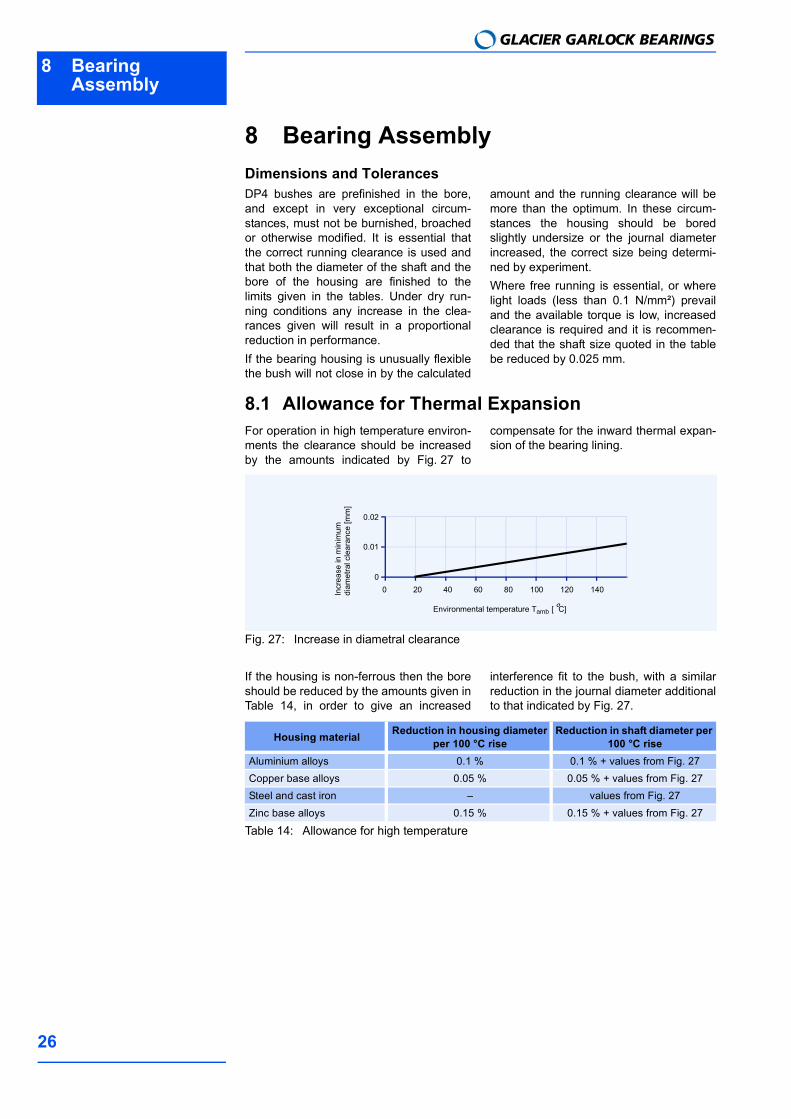
8.1 Allowance for Thermal ExpansionFor operation in high temperature environ-ments the clearance should be increasedby the amounts indicated by Fig. 27 to
compensate for the inward thermal expan-sion of the bearing lining.
Fig. 27: Increase in diametral clearance
If the housing is non-ferrous then the boreshould be reduced by the amounts given inTable 14, in order to give an increased
interference fit to the bush, with a similarreduction in the journal diameter additionalto that indicated by Fig. 27.
Table 14: Allowance for high temperature
Incr
ease
in m
inim
um
diam
etra
l cle
aran
ce [m
m]
Environmental temperature Tamb [°C]
0.01
0.02
0 40 60 800
20 100 120 140
Housing material Reduction in housing diameter per 100 °C rise
Reduction in shaft diameter per 100 °C rise
Aluminium alloys 0.1 % 0.1 % + values from Fig. 27Copper base alloys 0.05 % 0.05 % + values from Fig. 27Steel and cast iron values from Fig. 27Zinc base alloys 0.15 % 0.15 % + values from Fig. 27
8Bearing Assembly
27
8.2 Tolerances for minimum clearanceWhere it is required to keep the variation ofassembled clearance to a minimum, closertolerances can be specified towards the
upper end of the journal tolerance and thelower end of the housing tolerance.
If housings to H6 tolerance are used, thenthe journals should be finished to the follo-wing limits.
Table 15: Shaft tolerances for use with H6 housings
The sizes in Table 16 give the followingnominal clearance range.
Table 16: Clearance vs bearing diameter
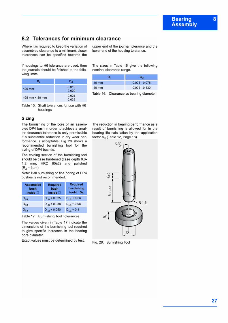
SizingThe burnishing of the bore of an assem-bled DP4 bush in order to achieve a smal-ler clearance tolerance is only permissibleif a substantial reduction in dry wear per-formance is acceptable. Fig. 28 shows arecommended burnishing tool for thesizing of DP4 bushes.The coining section of the burnishing toolshould be case hardened (case depth 0.6-1.2 mm, HRC 60±2) and polished(RZ ≈ 1µm).Note: Ball burnishing or fine boring of DP4bushes is not recommended.
Table 17: Burnishing Tool Tolerances
The values given in Table 17 indicate thedimensions of the burnishing tool requiredto give specific increases in the bearingbore diameter.Exact values must be determined by test.
The reduction in bearing performance as aresult of burnishing is allowed for in thebearing life calculation by the applicationfactor aC (Table 12, Page 18).
Fig. 28: Burnishing Tool
Di DJ
<25 mm -0.019-0.029
>25 mm < 50 mm -0.021-0.035
Di CD
10 mm 0.005 - 0.07850 mm 0.005 - 0.130
Assembled bush
Inside-∅
Required bush
Inside-∅
Required burnishing tool-∅ DC
Di,a Di,a + 0.025 Di,a + 0.06
Di,a Di,a + 0.038 Di,a + 0.08
Di,a Di,a + 0.050 Di,a + 0.1
0.5°
6±2
+10
Di
B 1B 1
DC
R 1.5
8 Bearing Assembly
GLACIER GARLOCK BEARINGS
28
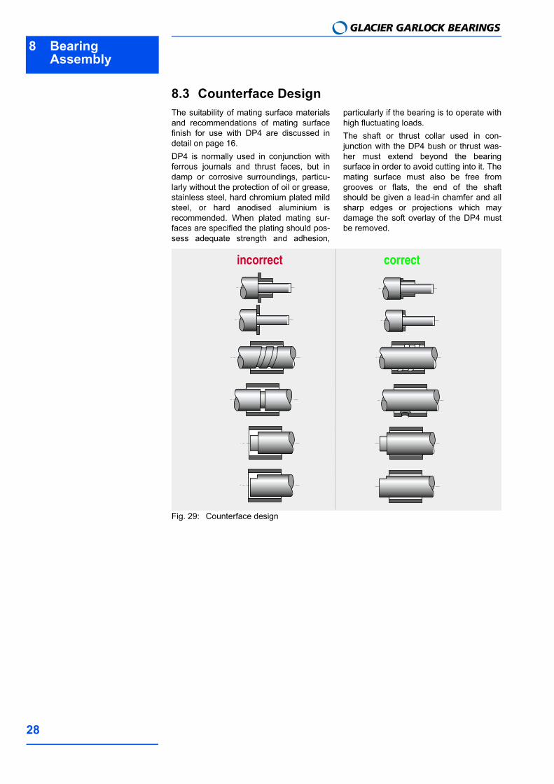
8.3 Counterface DesignThe suitability of mating surface materialsand recommendations of mating surfacefinish for use with DP4 are discussed indetail on page 16.DP4 is normally used in conjunction withferrous journals and thrust faces, but indamp or corrosive surroundings, particu-larly without the protection of oil or grease,stainless steel, hard chromium plated mildsteel, or hard anodised aluminium isrecommended. When plated mating sur-faces are specified the plating should pos-sess adequate strength and adhesion,
particularly if the bearing is to operate withhigh fluctuating loads.The shaft or thrust collar used in con-junction with the DP4 bush or thrust was-her must extend beyond the bearingsurface in order to avoid cutting into it. Themating surface must also be free fromgrooves or flats, the end of the shaftshould be given a lead-in chamfer and allsharp edges or projections which maydamage the soft overlay of the DP4 mustbe removed.
Fig. 29: Counterface design
incorrect correct
8Bearing Assembly
29
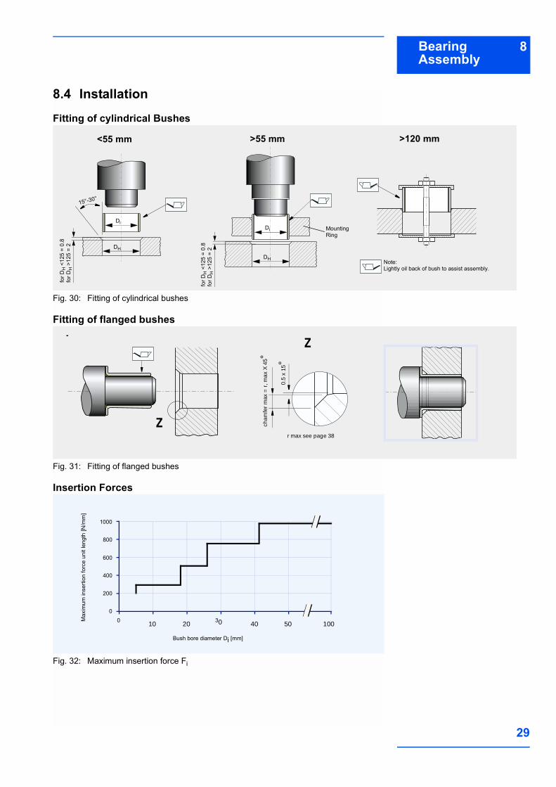
8.4 Installation
Fitting of cylindrical Bushes
Fig. 30: Fitting of cylindrical bushes
Fitting of flanged bushes
Fig. 31: Fitting of flanged bushes
Insertion Forces
Fig. 32: Maximum insertion force Fi
<55 mm >55 mm >120 mm
15°-30°
Mounting Ring
Note:Lightly oil back of bush to assist assembly.
for D
H <
125
= 0.
8fo
r DH
>12
5 =
2
DiDi
DH
DH
for D
H <
125
= 0.
8fo
r DH
>12
5 =
2
Z
Z cham
fer
max
= r
, max
X 4
5°
0.5
x 15
°
r max see page 38
Max
imum
inse
rtion
forc
e un
it le
ngth
[N/m
m]
Bush bore diameter Di [mm]
200
400
1000
0 30 40 50
800
0
20 100
600
10
8 Bearing Assembly
GLACIER GARLOCK BEARINGS
30
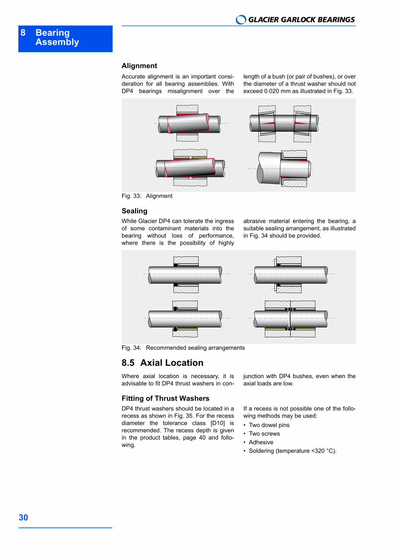
AlignmentAccurate alignment is an important consi-deration for all bearing assemblies. WithDP4 bearings misalignment over the
length of a bush (or pair of bushes), or overthe diameter of a thrust washer should notexceed 0.020 mm as illustrated in Fig. 33.
Fig. 33: Alignment
SealingWhile Glacier DP4 can tolerate the ingressof some contaminant materials into thebearing without loss of performance,where there is the possibility of highly
abrasive material entering the bearing, asuitable sealing arrangement, as illustratedin Fig. 34 should be provided.
Fig. 34: Recommended sealing arrangements
8.5 Axial LocationWhere axial location is necessary, it isadvisable to fit DP4 thrust washers in con-
junction with DP4 bushes, even when theaxial loads are low.
Fitting of Thrust WashersDP4 thrust washers should be located in arecess as shown in Fig. 35. For the recessdiameter the tolerance class [D10] isrecommended. The recess depth is givenin the product tables, page 40 and follo-wing.
If a recess is not possible one of the follo-wing methods may be used: Two dowel pins Two screws Adhesive Soldering (temperature <320 °C).
8Bearing Assembly
31
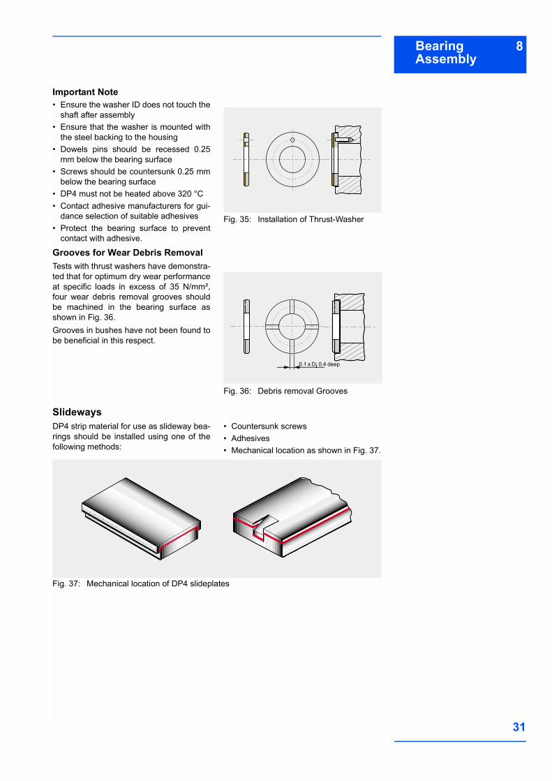
Important Note Ensure the washer ID does not touch the
shaft after assembly Ensure that the washer is mounted with
the steel backing to the housing Dowels pins should be recessed 0.25
mm below the bearing surface Screws should be countersunk 0.25 mm
below the bearing surface DP4 must not be heated above 320 °C Contact adhesive manufacturers for gui-
dance selection of suitable adhesives Protect the bearing surface to prevent
contact with adhesive.
Fig. 35: Installation of Thrust-Washer
Grooves for Wear Debris RemovalTests with thrust washers have demonstra-ted that for optimum dry wear performanceat specific loads in excess of 35 N/mm²,four wear debris removal grooves shouldbe machined in the bearing surface asshown in Fig. 36. Grooves in bushes have not been found tobe beneficial in this respect.
Fig. 36: Debris removal Grooves
SlidewaysDP4 strip material for use as slideway bea-rings should be installed using one of thefollowing methods:
Countersunk screws Adhesives Mechanical location as shown in Fig. 37.
Fig. 37: Mechanical location of DP4 slideplates
0.1 x Di 0.4 deep
9 ModificationGLACIER GARLOCK BEARINGS
32
9 Modification9.1 Cutting and MachiningThe modification of DP4 bearing compon-ents requires no special procedures. Ingeneral it is more satisfactory to performmachining or drilling operations from thePTFE side in order to avoid burrs. Whencutting is done from the steel side, the
minimum cutting pressure should be usedand care taken to ensure that any steel orbronze particles protruding into the remai-ning bearing material, and all burrs, areremoved.
Drilling Oil HolesBushes should be adequately supportedduring the drilling operation to ensure that
no distortion is caused by the drilling pres-sure.
Cutting Strip MaterialDP4 strip material may be cut to size byany one of the following methods. Care must be taken to protect the bearingsurface from damage and to ensure thatno deformation of the strip occurs: Using side and face cutter, or slitting
saw, with the strip held flat and securely
on a horizontal milling machine. Cropping Guillotine (For widths less than 90 mm
only) Water-jet cutting Laser cutting (see Health Warning).
9.2 Electroplating
DP4 ComponentsIn order to provide some protection inmildly corrosive environments the steelback and end faces of standard range DP4bearings are tin flashed. DP4 can be electroplated with most of theconventional electroplating metals inclu-ding the following: zinc ISO 2081 nickel ISO 1456 hard chromium ISO 1456.
For the harder materials if the specifiedplating thickness exceeds approximately 5 µm then the housing diameter should beincreased by twice the plating thickness inorder to maintain the correct assembledbearing bore size.Where electrolytic attack is possible testsshould be conducted to ensure that all thematerials in the bearing environment aremutually compatible.

10Standard Products
33
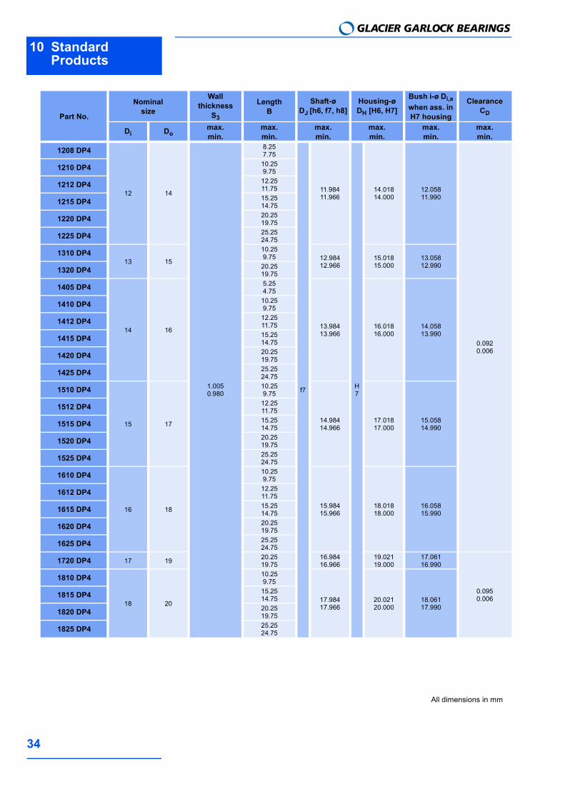
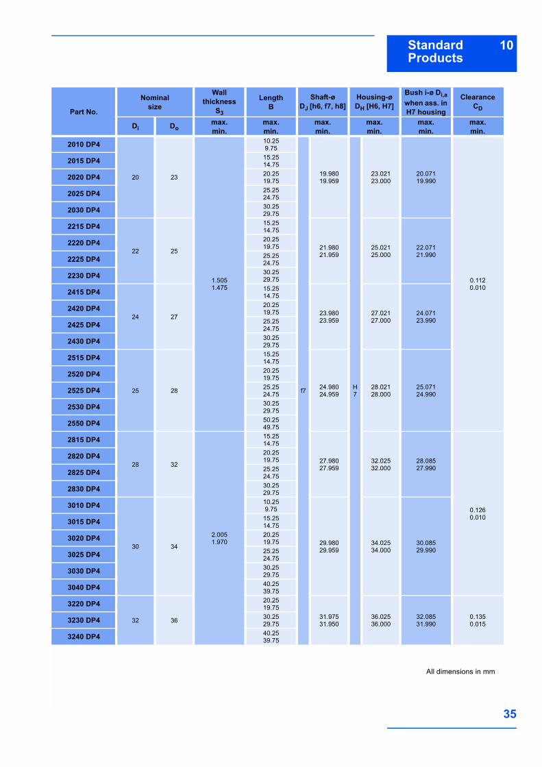
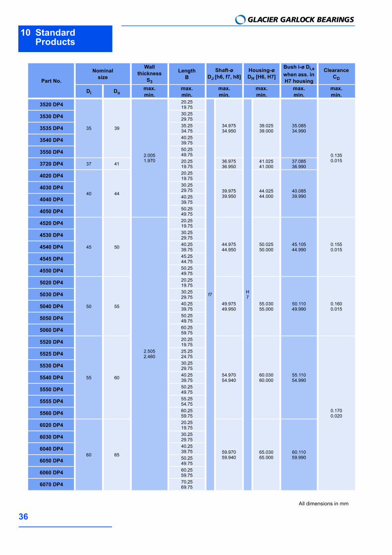
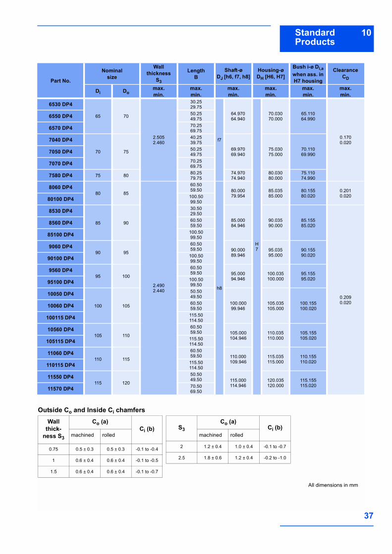
10 Standard Products10.1DP4 Cylindrical bushes
0.3
min
.
S3
Di
(Di,a
)
Do
Co
Ci
B
Z
20˚ ±8˚
Detail Z
Split
Dimensions and Tolerances according to ISO 3547 and GSP-Specifications
Part No.
Nominalsize
Wall thickness
S3
LengthB
Shaft-øDJ [h6, f7, h8]
Housing-øDH [H6, H7]
Bush i-ø Di,a when ass. in H7 housing
ClearanceCD
Di Domax.min.
max.min.
max.min.
max.min.
max.min.
max.min.
0203 DP4 2 3,5 0.7450.725 3.25
2.75
h6
2.0001.994
H6
3.5083.500
+2.058+2.010
0.0640.010
0303 DP43 4,5
0.7500.730
3.0002.994
4.5084.500
+ 3.048+ 3.000
0.0540.0000306 DP4 6.25
5.75
0404 DP44 5,5
4.253.75 4.000
3.9925.5085.500
+4.048+4.000
0.0560.0000410 DP4 10.25
9.75
0505 DP4
5 7
1.0050.980
5.254.75
f7
4.9904.978
H7
7.0157.000
5.0554.990
0.0770.000
0508 DP4 8.257.75
0510 DP4 10.259.75
0606 DP4
6 8
6.255.75
5.9905.978
8.0158.000
6.0555.9900608 DP4 8.25
7.75
0610 DP4 10.259.75
0710 DP4 7 9 10.259.75
6.9876.972
9.0159.000
7.0556.990
0.0830.003
0806 DP4
8 10
6.255.75
7.9877.972
10.01510.000
8.0557.990
0808 DP4 8.257.75
0810 DP4 10.259.75
0812 DP4 12.2511.75
1008 DP4
10 12
8.257.75
9.9879.972
12.01812.000
10.0589.990
0.0860.003
1010 DP4 10.259.75
1012 DP4 12.2511.75
1015 DP4 15.2514.75
1020 DP4 20.2519.75
All dimensions in mm
10 Standard Products
GLACIER GARLOCK BEARINGS
34
1208 DP4
12 14
1.0050.980
8.257.75
f7
11.98411.966
H7
14.01814.000
12.05811.990
0.0920.006
1210 DP4 10.259.75
1212 DP4 12.2511.75
1215 DP4 15.2514.75
1220 DP4 20.2519.75
1225 DP4 25.2524.75
1310 DP413 15
10.259.75 12.984
12.96615.01815.000
13.05812.9901320 DP4 20.25
19.75
1405 DP4
14 16
5.254.75
13.98413.966
16.01816.000
14.05813.990
1410 DP4 10.259.75
1412 DP4 12.2511.75
1415 DP4 15.2514.75
1420 DP4 20.2519.75
1425 DP4 25.2524.75
1510 DP4
15 17
10.259.75
14.98414.966
17.01817.000
15.05814.990
1512 DP4 12.2511.75
1515 DP4 15.2514.75
1520 DP4 20.2519.75
1525 DP4 25.2524.75
1610 DP4
16 18
10.259.75
15.98415.966
18.01818.000
16.05815.990
1612 DP4 12.2511.75
1615 DP4 15.2514.75
1620 DP4 20.2519.75
1625 DP4 25.2524.75
1720 DP4 17 19 20.2519.75
16.98416.966
19.02119.000
17.06116.990
0.0950.006
1810 DP4
18 20
10.259.75
17.98417.966
20.02120.000
18.06117.990
1815 DP4 15.2514.75
1820 DP4 20.2519.75
1825 DP4 25.2524.75
Part No.
Nominalsize
Wall thickness
S3
LengthB
Shaft-øDJ [h6, f7, h8]
Housing-øDH [H6, H7]
Bush i-ø Di,a when ass. in H7 housing
ClearanceCD
Di Domax.min.
max.min.
max.min.
max.min.
max.min.
max.min.
All dimensions in mm
10Standard Products
35
2010 DP4
20 23
1.5051.475
10.259.75
f7
19.98019.959
H7
23.02123.000
20.07119.990
0.1120.010
2015 DP4 15.2514.75
2020 DP4 20.2519.75
2025 DP4 25.2524.75
2030 DP4 30.2529.75
2215 DP4
22 25
15.2514.75
21.98021.959
25.02125.000
22.07121.990
2220 DP4 20.2519.75
2225 DP4 25.2524.75
2230 DP4 30.2529.75
2415 DP4
24 27
15.2514.75
23.98023.959
27.02127.000
24.07123.990
2420 DP4 20.2519.75
2425 DP4 25.2524.75
2430 DP4 30.2529.75
2515 DP4
25 28
15.2514.75
24.98024.959
28.02128.000
25.07124.990
2520 DP4 20.2519.75
2525 DP4 25.2524.75
2530 DP4 30.2529.75
2550 DP4 50.2549.75
2815 DP4
28 32
2.0051.970
15.2514.75
27.98027.959
32.02532.000
28.08527.990
0.1260.010
2820 DP4 20.2519.75
2825 DP4 25.2524.75
2830 DP4 30.2529.75
3010 DP4
30 34
10.259.75
29.98029.959
34.02534.000
30.08529.990
3015 DP4 15.2514.75
3020 DP4 20.2519.75
3025 DP4 25.2524.75
3030 DP4 30.2529.75
3040 DP4 40.2539.75
3220 DP4
32 36
20.2519.75
31.97531.950
36.02536.000
32.08531.990
0.1350.0153230 DP4 30.25
29.75
3240 DP4 40.2539.75
Part No.
Nominalsize
Wall thickness
S3
LengthB
Shaft-øDJ [h6, f7, h8]
Housing-øDH [H6, H7]
Bush i-ø Di,a when ass. in H7 housing
ClearanceCD
Di Domax.min.
max.min.
max.min.
max.min.
max.min.
max.min.
All dimensions in mm
10 Standard Products
GLACIER GARLOCK BEARINGS
36
3520 DP4
35 39
2.0051.970
20.2519.75
f7
34.97534.950
H7
39.02539.000
35.08534.990
0.1350.015
3530 DP4 30.2529.75
3535 DP4 35.2534.75
3540 DP4 40.2539.75
3550 DP4 50.2549.75
3720 DP4 37 41 20.2519.75
36.97536.950
41.02541.000
37.08536.990
4020 DP4
40 44
20.2519.75
39.97539.950
44.02544.000
40.08539.990
4030 DP4 30.2529.75
4040 DP4 40.2539.75
4050 DP4 50.2549.75
4520 DP4
45 50
2.5052.460
20.2519.75
44.97544.950
50.02550.000
45.10544.990
0.1550.015
4530 DP4 30.2529.75
4540 DP4 40.2539.75
4545 DP4 45.2544.75
4550 DP4 50.2549.75
5020 DP4
50 55
20.2519.75
49.97549.950
55.03055.000
50.11049.990
0.1600.015
5030 DP4 30.2529.75
5040 DP4 40.2539.75
5050 DP4 50.2549.75
5060 DP4 60.2559.75
5520 DP4
55 60
20.2519.75
54.97054.940
60.03060.000
55.11054.990
0.1700.020
5525 DP4 25.2524.75
5530 DP4 30.2529.75
5540 DP4 40.2539.75
5550 DP4 50.2549.75
5555 DP4 55.2554.75
5560 DP4 60.2559.75
6020 DP4
60 65
20.2519.75
59.97059.940
65.03065.000
60.11059.990
6030 DP4 30.2529.75
6040 DP4 40.2539.75
6050 DP4 50.2549.75
6060 DP4 60.2559.75
6070 DP4 70.2569.75
Part No.
Nominalsize
Wall thickness
S3
LengthB
Shaft-øDJ [h6, f7, h8]
Housing-øDH [H6, H7]
Bush i-ø Di,a when ass. in H7 housing
ClearanceCD
Di Domax.min.
max.min.
max.min.
max.min.
max.min.
max.min.
All dimensions in mm
10Standard Products
37
6530 DP4
65 70
2.5052.460
30.2529.75
f7
64.97064.940
H7
70.03070.000
65.11064.990
0.1700.020
6550 DP4 50.2549.75
6570 DP4 70.2569.75
7040 DP4
70 75
40.2539.75
69.97069.940
75.03075.000
70.11069.9907050 DP4 50.25
49.75
7070 DP4 70.2569.75
7580 DP4 75 80 80.2579.75
74.97074.940
80.03080.000
75.11074.990
8060 DP480 85
2.4902.440
60.5059.50
h8
80.00079.954
85.03585.000
80.15580.020
0.2010.02080100 DP4 100.50
99.50
8530 DP4
85 90
30.5029.50
85.00084.946
90.03590.000
85.15585.020
0.2090.020
8560 DP4 60.5059.50
85100 DP4 100.5099.50
9060 DP490 95
60.5059.50 90.000
89.94695.03595.000
90.15590.02090100 DP4 100.50
99.50
9560 DP495 100
60.5059.50 95.000
94.946100.035100.000
95.15595.02095100 DP4 100.50
99.50
10050 DP4
100 105
50.5049.50
100.00099.946
105.035105.000
100.155100.02010060 DP4 60.50
59.50
100115 DP4 115.50114.50
10560 DP4105 110
60.5059.50 105.000
104.946110.035110.000
105.155105.020105115 DP4 115.50
114.50
11060 DP4110 115
60.5059.50 110.000
109.946115.035115.000
110.155110.020110115 DP4 115.50
114.50
11550 DP4115 120
50.5049.50 115.000
114.946120.035120.000
115.155115.02011570 DP4 70.50
69.50
Part No.
Nominalsize
Wall thickness
S3
LengthB
Shaft-øDJ [h6, f7, h8]
Housing-øDH [H6, H7]
Bush i-ø Di,a when ass. in H7 housing
ClearanceCD
Di Domax.min.
max.min.
max.min.
max.min.
max.min.
max.min.
Outside Co and Inside Ci chamfersWall
thick-ness S3
Co (a)Ci (b)
machined rolled
0.75 0.5 ± 0.3 0.5 ± 0.3 -0.1 to -0.4
1 0.6 ± 0.4 0.6 ± 0.4 -0.1 to -0.5
1.5 0.6 ± 0.4 0.6 ± 0.4 -0.1 to -0.7
S3Co (a)
Ci (b)machined rolled
2 1.2 ± 0.4 1.0 ± 0.4 -0.1 to -0.7
2.5 1.8 ± 0.6 1.2 ± 0.4 -0.2 to -1.0
All dimensions in mm
10 Standard Products
GLACIER GARLOCK BEARINGS
38
10.2DP4 Flanged bushes
S3
S
Di (
Di,a
)
Do
fl
rmax = S3,nom
0.3
min
.
Dfl
Co
Ci
B
20˚ ±8˚
Z
Detail Z
Split
Dimensions and Tolerances according to ISO 3547 and GSP-Specifications
Part No.
Nominalsize
Wallthickness
S3
Flange thickness
Sfl
Flange-øDfl
LengthB
Shaft-øDJ [f7]
Housing-øDH [H7]
Ass.Inside-ø
Di,a
Clearance
CD
Di Domax.min.
max.min.
max.min.
max. min.
max.min.
max.min.
max.min.
max.min.
BB 0304 DP4 3 4,50.7500.730
0.800.70
7.56.5
4,253,75
3.0002.994
4.5084.500
3.0443.004
0.0540.000
BB 0404 DP4 4 5,5 9.58.5
4,253,75
4.0003.992
5.5085.500
4.0444.004
0.0560.000
BB 0505 DP4 5 7
1.0050.980
1.0050.800
10.59.5
5,254,75
4.9904.978
7.0157.000
5.0554.990
0.0770.000BB 0604 DP4
6 8 12.511.5
4.253.75 5.990
5.9788.0158.000
6.0555.990BB 0608 DP4 8.25
7.75
BB 0806 DP4
8 10 15.514.5
6.255.75
7.9877.972
10.01510.000
8.0557.990
0.0830.003BB 0808 DP4 8.25
7.75
BB 0810 DP4 10.259.75
BB 1007 DP4
10 12 18.517.5
7.256.75
9.9879.972
12.01812.000
10.0589.990
0.0860.003
BB 1009 DP4 9.258.75
BB 1012 DP4 12.2511.75
BB 1017 DP4 17.2516.75
BB 1207 DP4
12 14 20.519.5
7.256.75
11.98411.966
14.01814.000
12.05811.990
0.0920.006
BB 1209 DP4 9.258.75
BB 1212 DP4 12.2511.75
BB 1217 DP4 17.2516.75
BB 1412 DP414 16 22.5
21.5
12.2511.75 13.984
13.96616.01816.000
14.05813.990BB 1417 DP4 17.25
16.75
BB 1509 DP4
15 17 23.522.5
9.258.75
14.98414.966
17.01817.000
15.05814.990BB 1512 DP4 12.25
11.75
BB 1517 DP4 17.2516.75
BB 1612 DP416 18 24.5
23.5
12.2511.75 15.984
15.96618.01818.000
16.05815.990BB 1617 DP4 17.25
16.75
All dimensions in mm
10Standard Products
39
BB 1812 DP4
18 20 1.0050.980
1.0000.800
26.525.5
12.2511.75
17.98417.966
20.02120.000
18.06117.990
0.0950.006BB 1817 DP4 17.25
16.75
BB 1822 DP4 22.2521.75
BB 2012 DP4
20 23
1.5051.475
1.6001.400
30.529.5
11.7511.25
19.98019.959
23.02123.000
20.07119.990
0.1120.010
BB 2017 DP4 16.7516.25
BB 2022 DP4 21.7521.25
BB 2512 DP4
25 28 35.534.5
11.7511.25
24.98024.959
28.02128.000
25.07124.990BB 2517 DP4 16.75
16.25
BB 2522 DP4 21.7521.25
BB 3016 DP430 34
2.0051.970
2.1001.800
42.541.5
16.2515.75 29.980
29.95934.02534.000
30.08529.990
0.1260.010BB 3026 DP4 26.25
25.75
BB 3516 DP435 39 47.5
46.5
16.2515.75 34.975
34.95039.02539.000
35.08534.990
0.1350.015
BB 3526 DP4 26.2525.75
BB 4016 DP440 44 53.5
52.5
16.2515.75 39.975
39.95044.02544.000
40.08539.990BB 4026 DP4 26.25
25.75
BB 4516 DP445 50 2.505
2.4602.6002.400
58.557.5
16.2515.75 44.975
44.95050.02550.000
45.10544.990
0.1550.015BB 4526 DP4 26.25
25.75
Part No.
Nominalsize
Wallthickness
S3
Flange thickness
Sfl
Flange-øDfl
LengthB
Shaft-øDJ [f7]
Housing-øDH [H7]
Ass.Inside-ø
Di,a
Clearance
CD
Di Domax.min.
max.min.
max.min.
max. min.
max.min.
max.min.
max.min.
max.min.
Outside Co and Inside Ci chamfersWall
thick-ness S3
Co (a)Ci (b)
machined rolled
0.75 0.5 ± 0.3 0.5 ± 0.3 -0.1 to -0.4
1 0.6 ± 0.4 0.6 ± 0.4 -0.1 to -0.5
1.5 0.6 ± 0.4 0.6 ± 0.4 -0.1 to -0.7
S3Co (a)
Ci (b)machined rolled
2 1.2 ± 0.4 1.0 ± 0.4 -0.1 to -0.7
2.5 1.8 ± 0.6 1.2 ± 0.4 -0.2 to -1.0
All dimensions in mm
10 Standard Products
GLACIER GARLOCK BEARINGS
40
10.3DP4 Thrust Washers
dP
Di
DoST
d D
Ta
Do
d p
Part No.
Inside-øDi
Outside-øDo
ThicknessST
Locating Hole-ødD
Pitch Circle-ødP
Recess depthTa
max.min.
max.min.
max.min.
max.min.
max.min.
max.min.
WC 08 DP4 10.2510.00
20.0019.75
1.501.45
No Hole No Hole
1.200.95
WC 10 DP4 12.2512.00
24.0023.75
1.8751.625
18.1217.88
WC 12 DP4 14.2514.00
26.0025.75
2.3752.125
20.1219.88
WC 14 DP4 16.2516.00
30.0029.75
22.1221.88
WC 16 DP4 18.2518.00
32.0031.75
25.1224.88
WC 18 DP4 20.2520.00
36.0035.75
3.3753.125
28.1227.88
WC 20 DP4 22.2522.00
38.0037.75
30.1229.88
WC 22 DP4 24.2524.00
42.0041.75
33.1232.88
WC 24 DP4 26.2526.00
44.0043.75
35.1234.88
WC 25 DP4 28.2528.00
48.0047.75
4.3754.125
38.1237.88
WC 30 DP4 32.2532.00
54.0053.75
43.1242.88
WC 35 DP4 38.2538.00
62.0061.75
50.1249.88
WC 40 DP4 42.2542.00
66.0065.75
54.1253.88
WC 45 DP4 48.2548.00
74.0073.75
2.001.95
61.1260.88
1.701.45WC 50 DP4 52.25
52.0078.0077.75
65.1264.88
WC 60 DP4 62.2562.00
90.0089.75
76.1275.88
All dimensions in mm
10Standard Products
41
10.4DP4 Flanged Thrust Washers
10.5DP4 Strip
r 1.25
Dfl
d p
2 ±0.02
4,8 -0.6
Di
Do
1.5 x 45˚
r 1.25
5 ±0.1
8 ±
1
Part No.
Inside-øDi
Flange-øDfl
Outside-øDo
Locating Hole-ødP
ThicknessST
max.min.
max.min.
max.min.
max.min.
max.min.
BS 40 DP4 40.7040.20
44.0043.90
75.074.5
65.064.5
2.021.98
BS 50 DP4 51.5051.00
55.0054.88
85.084.5
75.074.5
BS 60 DP4 61.5061.00
65.0064.88
95.094.5
85.084.5
BS 70 DP4 71.5071.00
75.0074.88
110.0109.5
100.099.5
BS 80 DP4 81.5081.00
85.0084.86
120.0119.5
110.0109.5
BS 90 DP4 91.5091.00
95.0094.86
130.0129.5
120.0119.5
BS 100 DP4 101.50101.00
105.00104.86
140.0139.5
130.0129.5
Ss
Wu
L+3
W
Part No. LengthL
WidthW
Usable WidthWu
ThicknessSS
max.min.
S 07090 DP4
500
100 90 0.7400.700
S 10200 DP4
227 215
1.0100.970
S 15240 DP4 1.5101.470
S 20240 DP4 1.9801.940
S 25240 DP4 2.4602.420
All dimensions in mm
11 Test MethodsGLACIER GARLOCK BEARINGS
42
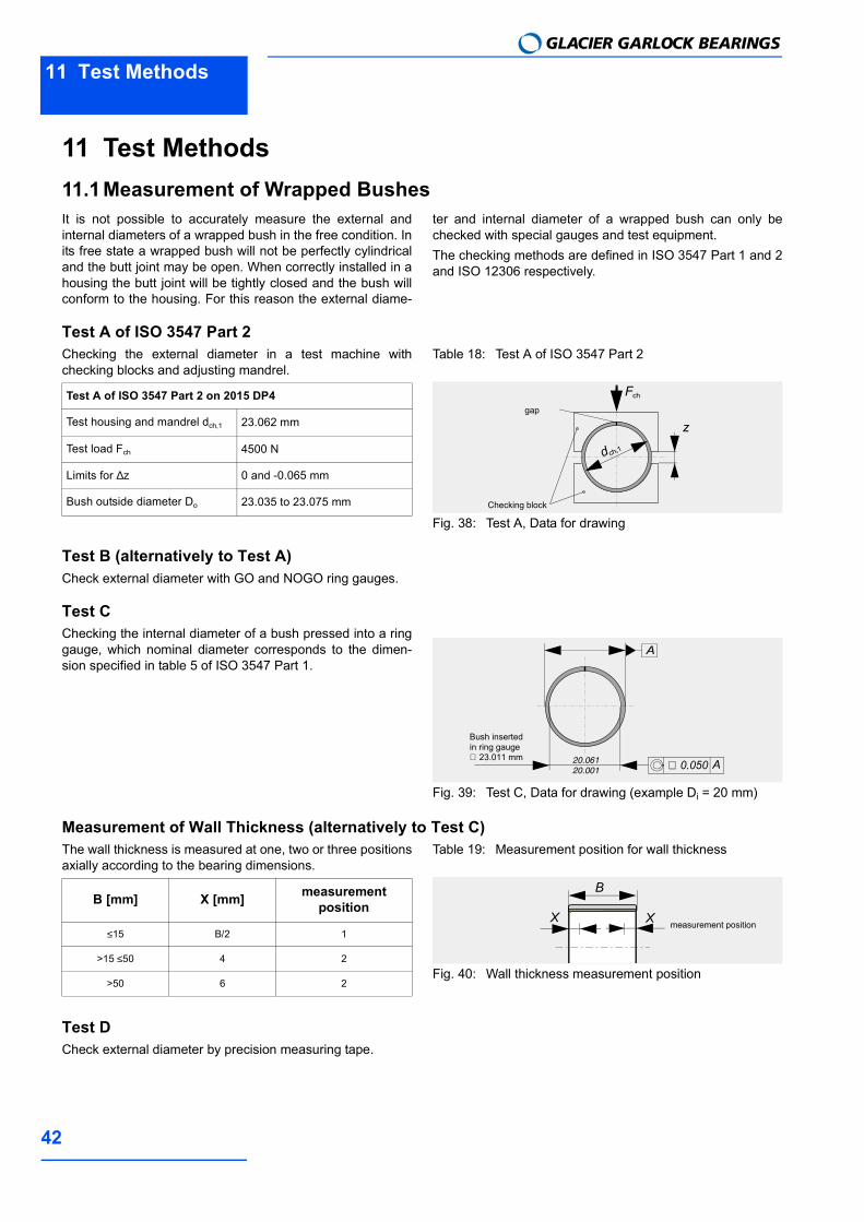
11 Test Methods11.1Measurement of Wrapped BushesIt is not possible to accurately measure the external andinternal diameters of a wrapped bush in the free condition. Inits free state a wrapped bush will not be perfectly cylindricaland the butt joint may be open. When correctly installed in ahousing the butt joint will be tightly closed and the bush willconform to the housing. For this reason the external diame-
ter and internal diameter of a wrapped bush can only bechecked with special gauges and test equipment.The checking methods are defined in ISO 3547 Part 1 and 2and ISO 12306 respectively.
Test A of ISO 3547 Part 2Checking the external diameter in a test machine withchecking blocks and adjusting mandrel.
Table 18: Test A of ISO 3547 Part 2
Fig. 38: Test A, Data for drawing
Test B (alternatively to Test A)Check external diameter with GO and NOGO ring gauges.
Test CChecking the internal diameter of a bush pressed into a ringgauge, which nominal diameter corresponds to the dimen-sion specified in table 5 of ISO 3547 Part 1.
Fig. 39: Test C, Data for drawing (example Di = 20 mm)
Measurement of Wall Thickness (alternatively to Test C)The wall thickness is measured at one, two or three positionsaxially according to the bearing dimensions.
Table 19: Measurement position for wall thickness
Fig. 40: Wall thickness measurement position
Test DCheck external diameter by precision measuring tape.
Test A of ISO 3547 Part 2 on 2015 DP4
Test housing and mandrel dch,1 23.062 mm
Test load Fch 4500 N
Limits for ∆z 0 and -0.065 mm
Bush outside diameter Do 23.035 to 23.075 mm Checking block
gap
z
dch,1
Fch
20.06120.001
Bush inserted in ring gauge ∅ 23.011 mm
A
A
∅ 0.050
B [mm] X [mm] measurementposition
≤15 B/2 1
>15 ≤50 4 2
>50 6 2
X X measurement position
B
Glacier Garlock Bearings warrants that products described in this bro-chure are free from defects in workmanship and material but unless expressly agreed in writing Glacier Garlock Bearings gives no war-ranty that these products are suitable for any particular purpose of for use under any specific conditions notwithstanding that such purpose would appear to be covered by this publication. Glacier Garlock Bea-rings accepts no liability for any loss, damage, or expense whatsoever arising directly or indirectly from use of its products. All business undertaken by Glacier Garlock Bearings is subject to its standard Conditions of Sale, copies of which are available upon request. Gla-cier Garlock Bearings products are subject to continual development and Glacier Garlock Bearings reserves the right to make changes in the specification and design of its products without prior notice.
GLACIERTM is a Trademark of the EnPro Industries Inc., USA.
DP4TM is a Trademark of the EnPro Industries Inc., USA.
This handbook was designed by Profidoc Silvia FreitagD-73433 Aalen
www.profidoc.de
Health Hazard - WarningFabricationAt temperatures up to 250 °C the polytetrafluroethylene (PTFE) pre-sent in the lining material is completely inert so that even on the rare occasions in which DP4 bushes are drilled, or sized, after assembly there is no danger in boring or burnishing. At higher temperatures however, small quantities of toxic fumes can be produced and the direct inhalation of these can cause an influenza type of illness which may not appear for some hours but which subsi-des without after-effects in 24-48 hours. Such fumes can arise from PTFE particles picked up on the end of a cigarette. Therefore smoking should be prohibited where DP4 is being machined.


![Mm2 Crazyness![1]](https://static.fdocuments.us/doc/165x107/558673bed8b42a08578b470f/mm2-crazyness1.jpg)


