DP SATA 6Gb/s 2S1P PCIe Installation Guide - siig.com SATA 6Gb/s 2S1P PCIe Installation Guide. 2...
20
1 04-0609B Introduction The DP SATA 6Gb/s 2S1P PCIe will add 2 SATA 6Gb/s & a PATA connectors to PCIe-equipped computers. Features and Benefits • Adds two SATA 6Gb/s and one PATA (IDE) connectors to your PCIe-enabled desktop PC enhancing existing systems with the latest SATA 6Gb/s technology • Ideal for bandwidth-hungry applications, such as multimedia content processing, video editing, port multiplier connectivity and fast transfers of large size files • Dual profile design to work with full height and low profile chassis with the included brackets • Compliant with Serial ATA Specification 3.0 • Compliant with PCI Express Base Specification, Revision 2.0 • Supports data transfer rate up to 6Gb/s on SATA 6Gb/s and 150Mb/s on PATA (IDE) connector • Supports hardware RAID 0 and 1 System Requirements • Desktop PC with an available PCIe slot • Windows ® 8 (32-/64-bit) / 7 (32-/64-bit) / Vista (32-/64-bit) / XP (32-/64-bit) / Server 2003 & 2008 (32-/64-bit) / Server 2008 R2 / Server 2012 DP SATA 6Gb/s 2S1P PCIe Installation Guide
Transcript of DP SATA 6Gb/s 2S1P PCIe Installation Guide - siig.com SATA 6Gb/s 2S1P PCIe Installation Guide. 2...

104-0609B
IntroductionThe DP SATA 6Gb/s 2S1P PCIe will add 2 SATA 6Gb/s &a PATA connectors to PCIe-equipped computers.
Features and Benefits• Adds two SATA 6Gb/s and one PATA (IDE)
connectors to your PCIe-enabled desktop PCenhancing existing systems with the latest SATA6Gb/s technology
• Ideal for bandwidth-hungry applications, such asmultimedia content processing, video editing, portmultiplier connectivity and fast transfers of largesize files
• Dual profile design to work with full height and lowprofile chassis with the included brackets
• Compliant with Serial ATA Specification 3.0• Compliant with PCI Express Base Specification,
Revision 2.0• Supports data transfer rate up to 6Gb/s on SATA
6Gb/s and 150Mb/s on PATA (IDE) connector• Supports hardware RAID 0 and 1
System Requirements• Desktop PC with an available PCIe slot• Windows® 8 (32-/64-bit) / 7 (32-/64-bit) / Vista
(32-/64-bit) / XP (32-/64-bit) / Server 2003 & 2008(32-/64-bit) / Server 2008 R2 / Server 2012
DP SATA 6Gb/s 2S1P PCIeInstallation Guide

2
Package Contents• DP SATA 6Gb/s 2S1P PCIe adapter• Spare low profile bracket• SATA and Ultra ATA data cables• Dual-connector SATA power cable• Sofware CD and Installation guide
Layout
Figure 1: DP SATA 6Gb/s 2S1P PCIe
* Note: Connect the hard disk drive activity LED ofthe system case to the pins horizontally. Thisconnection is optional.
Port 1
Port 2
Serial ATAConnectors
PATA (IDE)Connector
Port 1 LED(optional)*
Port 2 LED(optional)*
IDE LED(optional)*

3
Hardware InstallationGeneral instructions for installing the card are providedbelow. Since the design of computer cases andmotherboards vary, refer to your computer’ s referencemanual for further information, if needed.Static Electricity Discharge may permanently damageyour system. Discharge any static electricity build up inyour body by touching your computer case for a fewseconds. Avoid any contact with internal parts and handlecards only by their external edges.
1. Turn OFF the power to your computer and anyother connected peripheral devices.
2. Unplug the power cord from the back of thecomputer.
3. Remove your computer cover.4. Remove the slot bracket cover from an available PCI
Express slot.5. To install the card, carefully align the card's bus
connector with the selected PCI Express slot on themotherboard. Push the board down firmly, butgently, until it is well seated.
6. Replace the slot bracket holding screw to secure thecard.
Device ConnectionThe DP SATA 6Gb/s 2S1P PCIe adapter has a two channelSerial ATA controller that supports two Serial ATA harddisk drives and one PATA (IDE) channel that supportstwo IDE disk drives.

4
This controller supports hardware RAID 0 and 1. It isrecommended to use identical hard drives for all RAIDconfigurations, however, it's possible to combine harddrives of different sizes and makes. PATA (IDE) physicaldisks cannot be used to create a RAID set.
SATA Hard Disk Connector1. Install your hard disk drive(s) in the chassis.2. Connect the Serial ATA hard disk drive to the system
power supply using the included Dual ConnectorSerial ATA power cable.
Note: For hard drives with both SATA powerconnector and legacy 5-pin connector, use eitherthe SATA power connector or the legacy 5-pinpower connector. Using both power connectorsmay damage the hard drive.
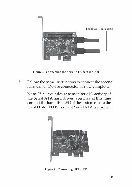
3. Connect one end of the Serial ATA data cable to thehard disk drive.
4. Attach the other end of the Serial ATA data cable to theSerial ATA connector on the DP SATA 6Gb/s 2S1PPCIe adapter.
Serial ATA data cable
Power cable
Figure 2. Hard disk drive connections
5
Figure 3. Connecting the Serial ATA data cable(s)
Serial ATA data cable
5. Follow the same instructions to connect the secondhard drive. Device connection is now complete.
Note: If it is your desire to monitor disk activity ofthe Serial ATA hard drives, you may at this timeconnect the hard disk LED of the system case to theHard Disk LED Pins on the Serial ATA controller.
Figure 4. Connecting HDD LED

6
PATA (IDE) Hard Disk ConnectionThe PATA (IDE) connector is a single channel Ultra ATA/133 channel that supports up to two IDE hard disk drivesor ATAPI devices.In order to achieve high-speed data transfer, a 40-pin/80-wire Ultra ATA ribbon cable is recommended. Also,do not mix Ultra ATA hard disks with slower IDE orATAPI devices on the same cable.
1. Attach one connector on the long end of the UltraATA ribbon cable to the board's PATA connectorand the other connector(s) to your IDE drive(s).Make sure pin 1 on the cable (indicated by thecolored stripe) matches pin 1 on the board's IDEconnector and your IDE drive(s).
2. When two drives are installed, make sure one driveis set up as Master and the other as Slave.
3. The Ultra ATA ribbon cable has two connectors. Ifyou install only one IDE drive, connect it to the endconnector of the cable and set it as Master. On theother hand, if you install two IDE drives, connect theMaster drive to the end connector of the cable andthe Slave drive in the middle connector.
4. Replace the computer cover and reconnect thesystem power and other peripherals to yourcomputer.
RAID ArraysThis controller can be configure for hardware RAID 0 and1, if needed. The PATA channel cannot be used for RAIDsetup. If you don't need RAID 0 or 1 and only use thiscontroller as a stand alone controller, please proceed toDriver Installation in page 9. RAID Arrays are setup inthe DP SATA 6Gb/s 2S1P PCIe adapter BIOS.

7
RAID 0 (Stripping)This RAID array to be used on New/Blank hard drives.Striping will destroy existing data on the hard drive.
1. As the BIOS boots press Ctrl+M when prompted toenter the RAID BIOS.
2. At the next screen select HBA Marvell 0, pressEnter. Select Configuration Wizard, then pressEnter.
3. Use Up or Down arrow key to choose hard drive.Press Spacebar to select the hard drive. Perform thesame procedure with the other hard drive. Onceboth hard drives are selected, press Enter.
4. Select RAID Level, press Enter. Select RAID 0, thenpress Enter.
Note: You can rename the VD Name. This isoptional.
5. Select Next, press Enter. When asked Do you wantto create this virtual disk? press Y to select Yes.
6. Press F10 to exit the BIOS. When asked Do you wantto exit from Marvell BIOS Setup? press Y to exitand reboot.
RAID 1 (Mirror)1. As the BIOS boots press Ctrl+M when prompted to
enter the RAID BIOS.2. At the next screen select HBA Marvell 0, press
Enter. Select Configuration Wizard, press Enter.3. Use Up or Down arrow key to choose hard drive.
Press Spacebar to select the hard drive. Perform thesame procedure with the other hard drive. Onceboth hard drives are selected press Enter.

8
4. Select RAID Level, press Enter. Select RAID1, thenpress Enter.
Note: You can rename the VD Name. This isoptional.
5. Select Next, press Enter. When asked Do you wantto create this virtual disk? press Y to select Yes.
6. Press F10 to exit the BIOS. When asked Do youwant to exit from Marvell BIOS Setup? press Y toexit and reboot.
Rebuilding a Failed Mirror SetWhen a failure to one member occurs, you will be notifiedeither by the RAID BIOS during boot up.The stepsbelow will guide you in rebuilding a failed mirror set.
1. Replace the failed drive with one of equal or greatercapacity, then power on the computer.
2. As the BIOS boots press Ctrl+M when prompted toenter the RAID BIOS.
3. Select VD 0, press Enter. Select Rebuild then pressEnter.
4. Select new hard drive under Free Physical Disks.5. Press Spacebar to select hard drive, then press
Enter.6. When asked Do you want to rebuild with selected
physical disk on this vd? press Y to select Yes. Themirror will begin rebuilding. Do not interfere withthe process until completion. Continue to step 7after completion.
7. Press F10 to exit the BIOS. When asked Do youwant to exit from Marvell BIOS setup? press Y toexit and reboot.

9
Deleting RAID Arrays1. As the BIOS boots press Ctrl+M when prompted to
enter the RAID BIOS.2. Select VD 0 press Enter. Select Delete then press
Enter.3. When asked Do you want to delete this virtual
disk? press Y to select Yes.4. When asked Do you want to delete MBR from this
virtual disk? press Y to select Yes.5. Press F10 to exit the BIOS. When asked Do you want
to exit from Marvell BIOS setup? press Y to exitand reboot.
Driver InstallationThis section provides information on how to install theDP SATA 6Gb/s 2S1P PCIe adapter drivers.
Server 2012For Server 2012, driver was already embedded in thesystem. Simply insert the card and boot up Windows, thecard is ready for use, no extra driver installation isneeded.
Windows 8 (32-/64-bit) / 7 (32-/64-bit) / Server2008 R2For New Installation1. Setup the RAID array prior to Windows installation.
If RAID is not required, go directly to step 2.2. Follow Windows installation procedure.3. At the Windows desktop, insert the driver CD, close
the CD autoplay window if prompted.

10
4. Press and release the Windows key and R keysimultaneously, type D:\Drivers\drvSetup.exe,click OK. (Change D: to match your CD-/DVD-ROM drive letter)
5. At the User Account Control, click Yes. Skip thisstep if not prompted.
6. At Magni driver Setup, click Next, and click Nextagain.
7. Change the Destination Folder if you want to changeit; otherwise, click Install.
8. Click Finish, then restart the computer to completethe installation.
For Existing Installation1. Setup the RAID array prior to driver installation and
boot up to Windows. If RAID is not required, bootup to Windows and go directly to step 2.
2. Insert the driver CD, close the CD autoplay windowif prompted.
3. Click Windows key and R, type D:\Drivers\drvSetup.exe, click OK. (Change D: to match yourCD-/DVD-ROM drive letter)
4. At the User Account Control, click Yes. Skip thisstep if not prompted.
5. At Magni driver Setup, click Next, and click Nextagain.
6. Change the Destination Folder if you want to changeit; otherwise, click Install.
7. Click Finish, then restart the computer.

11
Windows Vista (32-/64-bit) / Server 2008 (32-/64-bit)For A New Installation1. Setup the RAID array prior to Windows installation.2. Follow Windows installation procedure.3. After booting up the Windows, click Cancel at the
Found New Hardware window.4. Insert the driver CD, close the CD autoplay window
if prompted.5. Click Start, at the Start Search, typeD:\Drivers\drvSetup.exe, click Enter. (Change D:to match your CD-/DVD-ROM drive letter)
6. At the User Account Control, click Continue. Skipthis step if not prompted.
7. At Magni driver Setup, click Next, and click Nextagain.
8. Change the Destination Folder if you want to changeit; otherwise, click Install.
9. Click Finish, then restart the computer.
For Existing Installation1. Setup the RAID array prior to driver installation and
boot up to Windows. If RAID is not required, godirectly to step 2.
2. Click Cancel at the Found New Hardware window.3. Insert the driver CD, close the CD autoplay window
if prompted.4. Click Start, at the Start Search, type D:\Drivers\
drvSetup.exe, click Enter. (Change D: to match yourCD-/DVD-ROM drive letter)
5. At the User Account Control, click Continue. Skipthis step if not prompted.

12
6. At Magni driver Setup, click Next, and click Nextagain.
7. Change the Destination Folder if you want to changeit; otherwise, click Install.
8. Click Finish, then restart the computer.
Windows XP (32-/64-bit) / Server 2003 (32-/64-bit)For A New Installation (32-bit)A new installation requires a floppy disk for the driverinstallation. To make this floppy disk, copy the contentsof the Floppy32 folder which is under Drivers/ miniportfolder on the driver CD onto a blank floppy disk, thenfollow the directions below.
1. Setup the RAID array prior to Windows installation.If RAID is not required, go directly to step 2.
2. Follow Windows installation procedure.3. At the Windows Setup screen, press F6 to install the
RAID driver.4. When prompted, press S to specify the location of
the driver.5. Insert the floppy disk, then press Enter.6. Select Marvell shared library (install first), then
press Enter.7. Press S to specify the location of the driver. Select
Marvell 91xx SATA controller 32bit Driver, thenpress Enter.
Note: Do not remove the floppy diskette from thefloppy drive. You need to install the driver againduring the installation.

13
8. Press Enter again to finish the driver installation,then follow the on-screen instructions to completeyour Windows installation.
9. After the installation, insert the driver CD. Close theCD autoplay window if prompted.
10. Click Start , Run, type D:\Drivers\drvSetup.exe,click OK. (Change D: to match yourCD-/DVD-ROM drive letter)
11. At Magni driver Setup, click Next, and click Nextagain.
12. Change the Destination Folder if you want to changeit; otherwise, click Install.
13. Click Finish, then restart the computer to completethe installation.
For A New Installation (64-bit)A new installation requires a floppy disk for the driverinstallation. Copy the contents of the Floppy64 folderwhich is under Drivers/ miniport on the driver CD, ontoa blank floppy disk, then follow the directions below.
1. Setup the RAID array prior to Windows installation.If RAID is not required, go directly to step 2.
2. Follow Windows installation procedure.3. At the Windows Setup screen, press F6 to install the
RAID driver.4. When prompted, press S to specify the location of
the driver.5. Insert the floppy disk, then press Enter.6. Select Marvell shared library (install first), then
press Enter.

14
7. Press S to specify the location of the driver. SelectMarvell 91xx SATA controller 64bit Driver, thenpress Enter.
Note: Do not remove the floppy diskette from thefloppy drive. You need to install the driver againduring the installation.
8. Press Enter again to finish the driver installation,then follow the on-screen instructions to completeyour Windows installation.
9. After the installation, insert the driver CD. Close theCD autoplay window if prompted.
10. Click Start , Run, type D:\Drivers\drvSetup.exe,click OK. (Change D: to match your CD-/DVD-ROM drive letter)
11. At Magni driver Setup, click Next, and click Nextagain.
12. Change the Destination Folder if you want to changeit, otherwise, click Install.
13. Click Finish, then restart Windows.
For Existing Installation1. Setup the RAID array prior to driver installation and
boot up to Windows. If RAID is not required, bootup to Windows and go directly to step 2.
2. Click Cancel at the Found New Hardware.3. Insert the driver CD, close the CD autoplay window
if prompted.4. Click Start , Run, type D:\Drivers\ drvSetup.exe,
click OK. (Change D: to match your CD-/DVD-ROM drive letter)
15
5. At Magni driver Setup, click Next, and click Nextagain.
6. Change the Destination Folder if you want to changeit; otherwise, click Install.
7. Click Finish, then restart Windows.
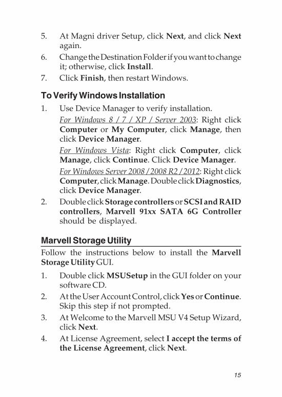
To Verify Windows Installation1. Use Device Manager to verify installation.
For Windows 8 / 7 / XP / Server 2003: Right clickComputer or My Computer, click Manage, thenclick Device Manager.For Windows Vista: Right click Computer, clickManage, click Continue. Click Device Manager.For Windows Server 2008 / 2008 R2 / 2012: Right clickComputer, click Manage. Double click Diagnostics,click Device Manager.
2. Double click Storage controllers or SCSI and RAIDcontrollers, Marvell 91xx SATA 6G Controllershould be displayed.
Marvell Storage UtilityFollow the instructions below to install the MarvellStorage Utility GUI.
1. Double click MSUSetup in the GUI folder on yoursoftware CD.
2. At the User Account Control, click Yes or Continue.Skip this step if not prompted.
3. At Welcome to the Marvell MSU V4 Setup Wizard,click Next.
4. At License Agreement, select I accept the terms ofthe License Agreement, click Next.

16
5. Click Next again.6. Change the Destination folder if you want to change
it; otherwise, click Install.7. Click Allow access at the Windows Security Alert.
Skip this step if not prompted.8. At the Completing the Marvell MSU V4 Setup
Wizard, click Finish.10. After successful installation, the MSU GUI is ready
for use. Enable the software by double click on it.11. Type in the Username and Password to log in.
Username and Password are your Windows username and password. If you have a user name but nopassword, please leave the password field blank.See Figure 5.
Figure 5
12. After log in, you can access to the MSU user interfacefor further VD management. See Figure 6.Refer to your UserGuide on the software CD formore details.

17
Figure 6

18
Blank Page

19
Technical Support and WarrantyQUESTIONS? SIIG’ s Online Support has answers! Simply visit our web siteat www.siig.com and click Support. Our online support database is updateddaily with new drivers and solutions. Answers to your questions could be justa few clicks away. You can also submit questions online and a technical supportanalyst will promptly respond.SIIG offers a lifetime manufacturer warranty with this product. This warrantycovers the original purchaser and guarantees the product to be free of anydefects in materials or workmanship for the life of the product.SIIG will, at our discretion, repair or replace (with an identical product orproduct having similar features and functionality) the product if defective inmaterials or workmanship. This warranty gives you specific legal rights, andyou may also have other rights which vary from state to state. Please see ourweb site for more warranty details.If you encounter any problems with this product, please follow the proceduresbelow.A) If it is within the store's return policy period, please return the product tothe store where you purchased it.B) If your purchase has passed the store's return policy period, please followthese steps to have the product repaired or replaced.
Step 1: Submit your RMA request. Go to www.siig.com, click Support,then Request A Product Replacement to submit a request to SIIG RMA orfax a request to 510-657-5962. Your RMA request will be processed, if theproduct is determined to be defective, an RMA number will be issued.Step 2: After obtaining an RMA number, ship the product.• Properly pack the product for shipping. All software, cable(s) and any
other accessories that came with the original package must be included.• Clearly write your RMA number on the top of the returned package.
SIIG will refuse to accept any shipping package, and will not beresponsible for a product returned without an RMA number posted onthe outside of the shipping carton.
• You are responsible for the cost of shipping to SIIG. Ship the productto the following address:SIIG, Inc.6078 Stewart AvenueFremont, CA 94538-3152, USARMA #:
• SIIG will ship the repaired or replaced product via Ground in the U.S.and International Economy outside of the U.S. at no cost to thecustomer.
About SIIG, Inc.Founded in 1985, SIIG, Inc. is a leading manufacturer of IT connectivitysolutions (including Serial ATA and Ultra ATA Controllers, FireWire, USB,and legacy I/O adapters) that bridge the connection between Desktop/Notebook systems and external peripherals. SIIG continues to grow byadding A/V and Digital Signage connectivity solutions to our extensiveportfolio. All centered around the distribution and switching of A/V signalsover CAT5/6, these products include matrix switches, distribution amplifiers,extenders, converters, splitters, cabling, and more.SIIG is the premier one-stop source of upgrades and is committed toproviding high quality products while keeping economical and competitiveprices. High-quality control standards are evident by one of the lowestdefective return rates in the industry. Our products offer comprehensiveuser manuals, user-friendly features, and most products are backed by alifetime warranty.SIIG products can be found in many computer retail stores, mail ordercatalogs, and e-commerce sites in the Americas, as well as through majordistributors, system integrators, and VARs.
PRODUCT NAMEDP SATA 6Gb/s 2S1P PCIe
FCC RULES: TESTED TO COMPLY WITH FCC PART 15, CLASSB OPERATING ENVIRONMENT: FOR HOME OR OFFICE USE
FCC COMPLIANCE STATEMENT:This device complies with part 15 of the FCC Rules. Operation issubject to the following two conditions: (1) This device may not causeharmful interference, and (2) this device must accept any interferencereceived, including interference that may cause undesired operation.
THE PARTY RESPONSIBLE FOR PRODUCT COMPLIANCE
SIIG, Inc.6078 Stewart AvenueFremont, CA 94538-3152, USAPhone: 510-657-8688
DP SATA 6Gb/s 2S1P PCIe is a trademark of SIIG, Inc. SIIG and the SIIG logo are registered trademarksof SIIG, Inc. Microsoft and Windows are registered trademarks of Microsoft Corporation. All othernames used in this publication are for identification only and may be trademarks of their respectiveowners.
December, 2013 Copyright © 2013 by SIIG, Inc. All rights reserved.


![Pricelist · 2020. 5. 20. · 512GB Adata DP900 SSD 2.5 inch SATA 6Gb/s, 1M Hrs MTBF [CS] -39 256GB ADATA Solid State Drive 2.5 inch SATA 6Gb/s [CS] -39 252-10007 256GB ADATA Solid](https://static.fdocuments.us/doc/165x107/5fe5a366dd0b2532737c2eb0/pricelist-2020-5-20-512gb-adata-dp900-ssd-25-inch-sata-6gbs-1m-hrs-mtbf.jpg)