DP Bøtker
35
1 Dynamically Positioned FPSO with Disconnectable Riser Buoy Flexible FPSO Design for Numerous Applications Tekna Thursday the 19 th June Holmen Fjordhotel Stig Bøtker Sales & Marketing Manager
-
Upload
armi-valdez -
Category
Documents
-
view
10 -
download
0
description
fpsocean
Transcript of DP Bøtker

1
Dynamically Positioned FPSO with Disconnectable Riser Buoy
Flexible FPSO Design for Numerous Applications
Tekna
Thursday the 19th June Holmen Fjordhotel
Stig Bøtker Sales & Marketing Manager

Presentation Overview
� Company introduction
� Setting the scene
� Generic design
� Main components of a DP FPSO
� Project Status
� Concluding remarks
2

Company Introduction - General
� FPSOcean was established in 2005 by individuals with substantial
experience in founding and running world class oil service contractors
� FPSOcean’s vision is to become a significant niche player in the global
market for floating production system in deep to ultra deep waters
� Our business model is to build, own and operate Floating Production
Systems
� FPSOcean has established a long term partnership for Technical
Management & Operations with Aberdeen-based Bibby Offshore and
Houston-based Greystar Corporation
� The company has a goal of developing a fleet of 5 units over the next 4-6
years
� Main office is in Oslo, site office in Dubai & customer support offices in
Rio de Janeiro and Houston
3

4
Company Introduction - Projects
FPSO conversion ongoing, deepwater technology being developed
� “DeeP Producer 1” (DPP1); Panamax shuttle tanker “Nordic
Laurita”, built Tsuneishi Japan 1981, delivered in July 2006,
dry-docked and classed August 2006, entered Drydocks World
Dubai May 2007 for conversion to Dynamic Positioning FPSO.
Ready for First Oil end 2008/early 2009 pending field specific
items.
� “DeeP Producer 2” (DPP2); Double sided Aframax tanker
“Semakau Spirit”, built Koyo Japan 1988, purchased for
delivery July 2008. Scheduled completion end Q3 2010. Long
lead items secured.

Setting the Scene - The New Deep Water Frontiers
� Deep to ultra deep waters (1000 m down to 3000 m)
� Areas may be prone to hurricanes and typhoons
� No infrastructure
� Challenging reservoir
� Sub-salt
� Heavy oil
� High pressure
� New geological areas
5
Characterized by

Setting the Scene - The New Deep Water Frontiers
� Determine reservoir parameters
� Confirmation of reserves, depletion strategy and full field
development
� High risk level
� Cash flow and schedule of full field development
6
Field development challengers

7
Setting the Scene - The new Deep Water Frontiers
� Generic designed Dynamic Positioned FPSO’s
The solution offer
� Increased definition of
reservoir parameters
� Minimum lead time
� Independency of infrastructure
� Easily deployable and
redeployable
� Cash flow improvement
The solution to the field development challenge
Conventional Development
Extended Well Testing
Early Production
Exploration OperationAppraisal Execution
Project Cash Flow

Setting the Scene -Why DP ?
� Station keeping by dynamic positioning is independent of water depth
�The deeper the water the more competitive is Dynamic Positioning
�Easily deployable and easily re-deployable to new locations
�Dynamic Positioning systems have proved very favourable in subsea
construction, drilling and shuttle tanker segments
� 20 years successful experience with Seillean DP FPSO in UK and Brazil
8

Setting the Scene - Development Scenarios
Scenario Field size
Extended Well Testing Significant
Early Production System Significant
Marginal Field Development Marginal
Environmental Exposed Development Marginal to medium
9
FPSOCean head office
FPSOCean sales offic
Partner offices
Target Areas

10
Generic Design
� To make the DeeP Producer 1 suitable for a variety of fields but still
keep the cost low to allow the concept to be attractive to several
potential clients
Key to success
� To build flexibility into the design but still be able to defer decisions
with significant cost impact related to functions which may not be
required for all field development
Important issues when freezing the Generic Design
� Environmental design criteria
� Topside Facilities
� Process capacity
Dilemma

11
Generic Design - Environmental Criteria
Impact of design criteria
� Selection of conversion candidates
� Size of/number of thrusters and the power plant
� General facility design
� Areas where the DeeP Producer 1 can operate
� Operational uptime
Environment used in generic design
� Structural Integrity based on a Hs 10 meter
� Stay on location in a Hs of minimum 7,5 meter
� Operation in a Hs of minimum 6,0 meter
� Typical current and wind conditions for offshore Brazil, Gulf of Mexico and West
of Africa

12
Generic Design – Environmental Criteria
The selected environmental design criteria
� Allow operation in the majority of the new deep water frontiers
without controlled disconnect due to adverse environmental
conditions
� May result in controlled disconnect in hurricanes and typhoon
areas
� Allow operation in area with harsher environment though multiple
disconnect and a reduced uptime may be experienced

13
Generic Design - Topside Facilities
� Functions incorporated into basic generic design.
� Functions the topside has been prepared for to incorporate.
� Functions not incorporated into the topside or not
prepared for.
To be able to minimize cost, defer important decisions and still
make the vessel flexible, three topside function categories has
been developed

14
Generic Design - Topside Facilities
� Receive well fluid from the inlet manifold.
� Separate oil, gas and water.
� Stabilize and deliver crude oil to storage tanks within
specified standards.
� Condition produced water and dump it to sea.
� Condition produced gas to deliver it as fuel gas to gas
turbines or to the flare.
Functions incorporated into basic generic design.
15
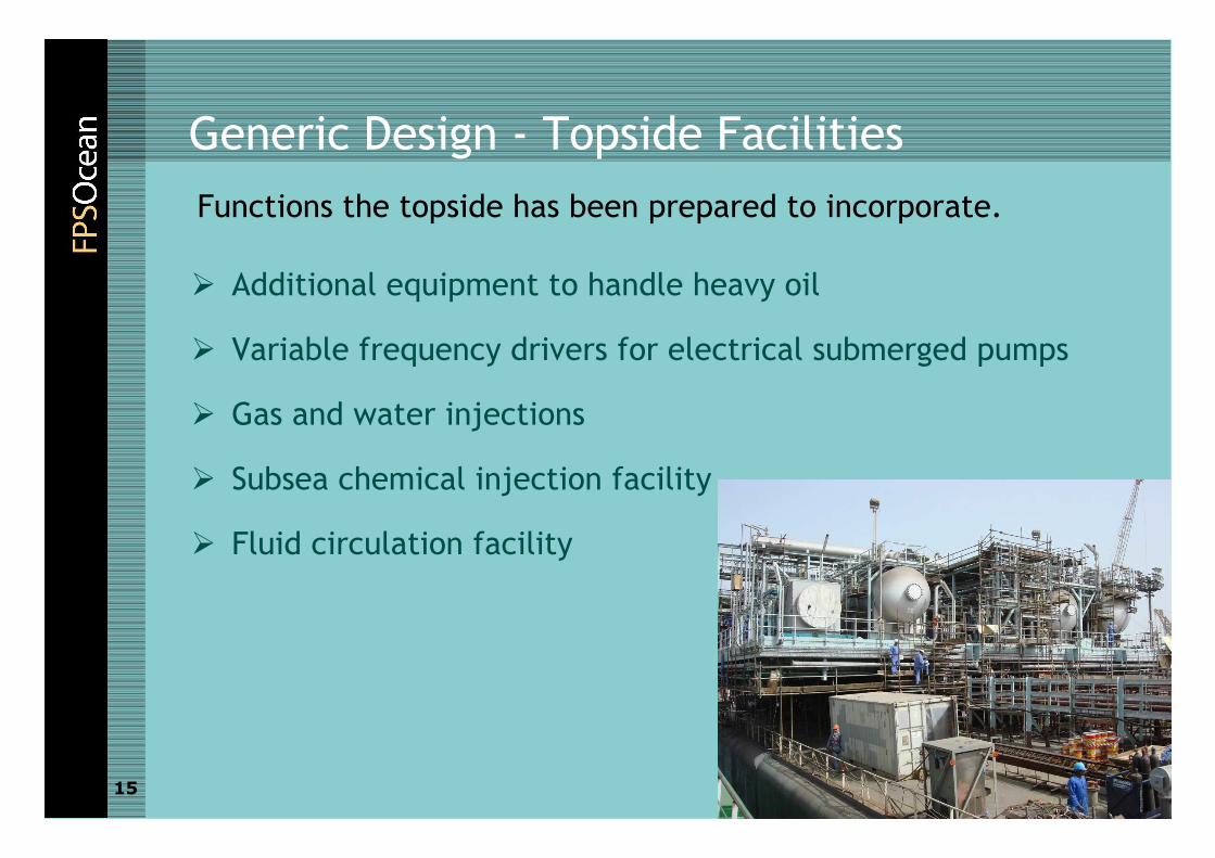
Generic Design - Topside Facilities
� Additional equipment to handle heavy oil
� Variable frequency drivers for electrical submerged pumps
� Gas and water injections
� Subsea chemical injection facility
� Fluid circulation facility
Functions the topside has been prepared to incorporate.

16
Generic Design - Topside Facilities
� Gas compression and export
� Very large GOR ratios
� Design for high content of CO2 and H2S
� High pressure
� Gas to liquid plant
Equipment/functions not incorporated into the topside or
not prepared for

17
Generic Design - Topside Facilities
� The selected strategy will allow the DeeP Producer 1 to
produce from the most deepwater oil reservoirs without
jeopardizing the schedule for the full field development
� The DeeP Producer 1 will not be able to producer from gas
fields without impact on schedule
Topside Facility Conclusion

18
Generic Design - Process capacity
� Number of wells to be tied in and the flow from each well
� Vessel size
� Revenue versus day rate
Selected capacity
� Liquid capacity 60 000 bpd
� Oil capacity 40 000 bpd
� Water production 20 000 bpd
� Gas oil Ratio <1000
Process capacity requirement for an EWT or EP facility is
determined by
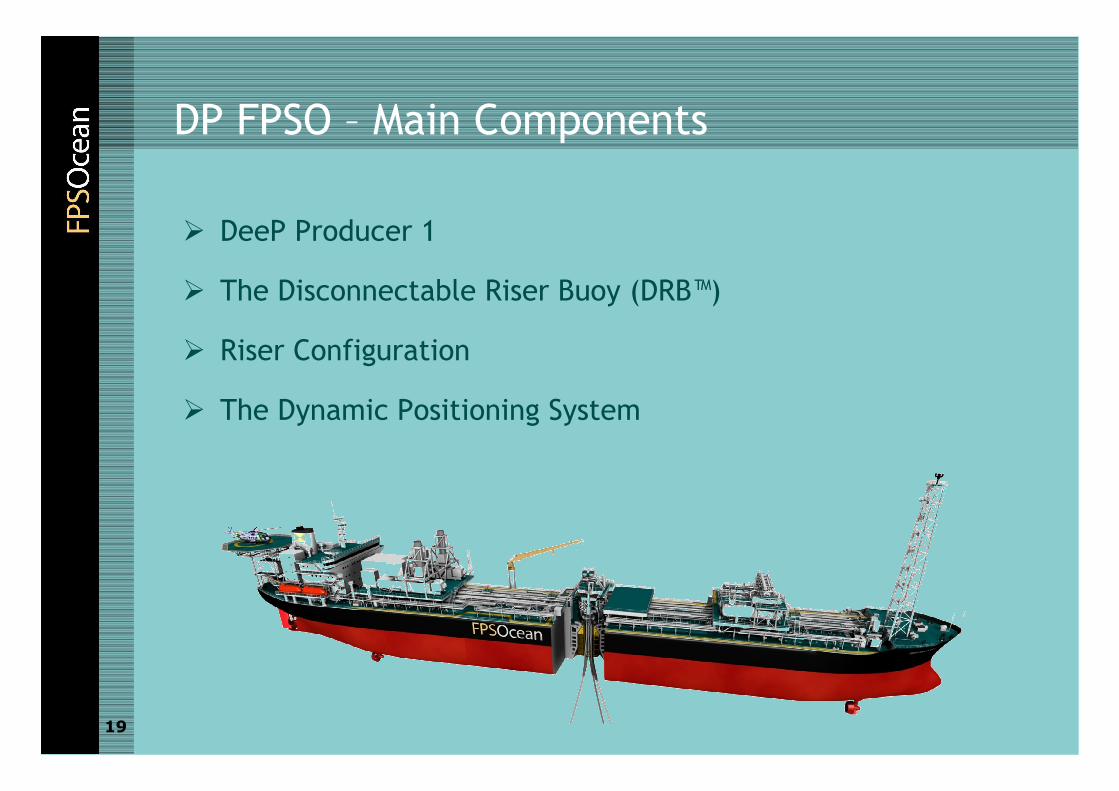
DP FPSO – Main Components
� DeeP Producer 1
� The Disconnectable Riser Buoy (DRB™)
� Riser Configuration
� The Dynamic Positioning System
19
20
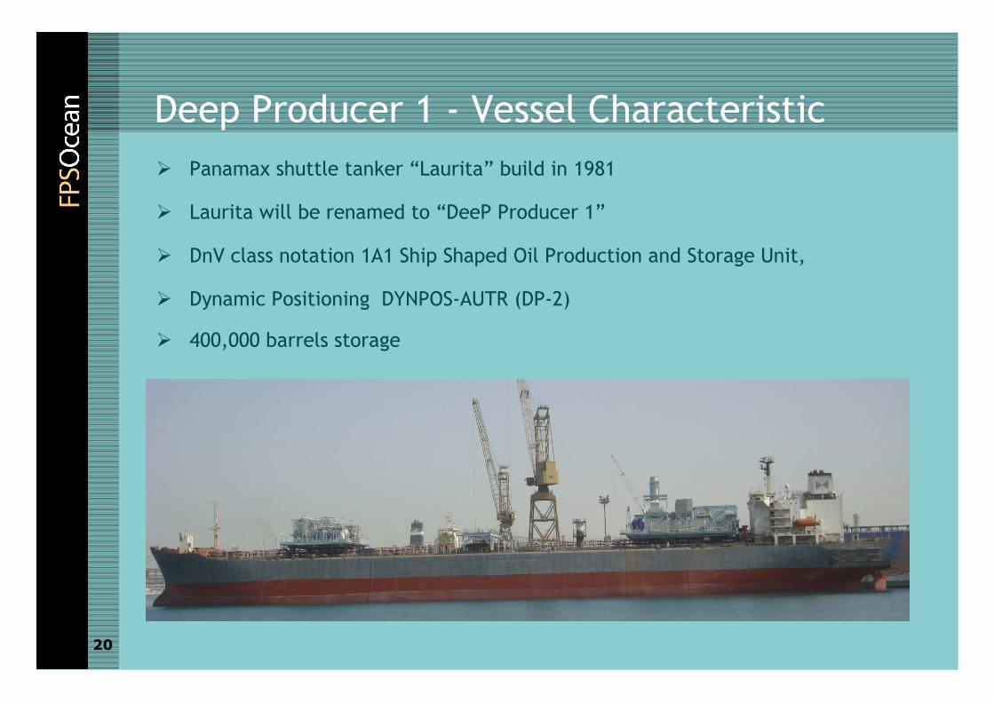
Deep Producer 1 - Vessel Characteristic
� Panamax shuttle tanker “Laurita” build in 1981
� Laurita will be renamed to “DeeP Producer 1”
� DnV class notation 1A1 Ship Shaped Oil Production and Storage Unit,
� Dynamic Positioning DYNPOS-AUTR (DP-2)
� 400,000 barrels storage
DeeP Producer 1
21

DP FPSO – Full Field Development Configuration
� Design used for stability and global strength calculation
� Gas injection module, two process modules, subsea
chemical injection module and water injection module
22

23
DP FPSO - Disconnectable Riser Buoy (DRBTM)
� The DRBTM is developed & owned jointly by
FPSOcean & Scana
� An internal turret with an active turning drive
controled by the vessel ICS/heading control.
� A multipath riser connector with built-in ESD ball
valves.
� A 5-path fluid toroid swivel + multipath hydraulic
swivel and electric swivel.
� Quick dis-connect for operational safety
� Dis-connected DRBTM stabilised in ≈40 m below
surface
Key technology element allowing tie-in of multiple risers

24
DP FPSO - Disconnetable Riser Buoy™

DP FPSO - Riser Configurations
00
500500
10001000
15001500
20002000
25002500
Pliant wave Hybrid Mid water archPliant wave Hybrid Mid water arch Deep wave CatenaryDeep wave Catenary
Umbil ical (red)
OP Riser (yellow)
Polyester Tether (white)
1mt/m Chain (blue)
3-inch Chain (green)
Buoyancy (green)
WI Riser (yellow)
Multiple Risers Single Riser
26
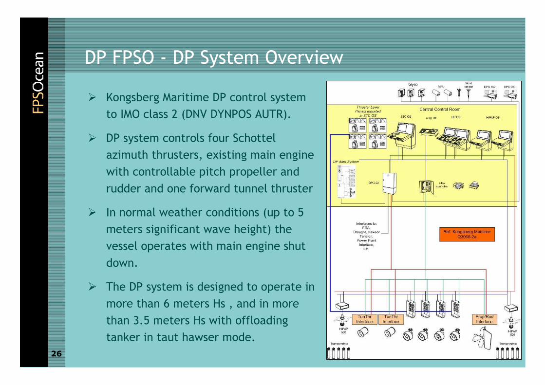
DP FPSO - DP System Overview
� Kongsberg Maritime DP control system
to IMO class 2 (DNV DYNPOS AUTR).
� DP system controls four Schottel
azimuth thrusters, existing main engine
with controllable pitch propeller and
rudder and one forward tunnel thruster
� In normal weather conditions (up to 5
meters significant wave height) the
vessel operates with main engine shut
down.
� The DP system is designed to operate in
more than 6 meters Hs , and in more
than 3.5 meters Hs with offloading
tanker in taut hawser mode.
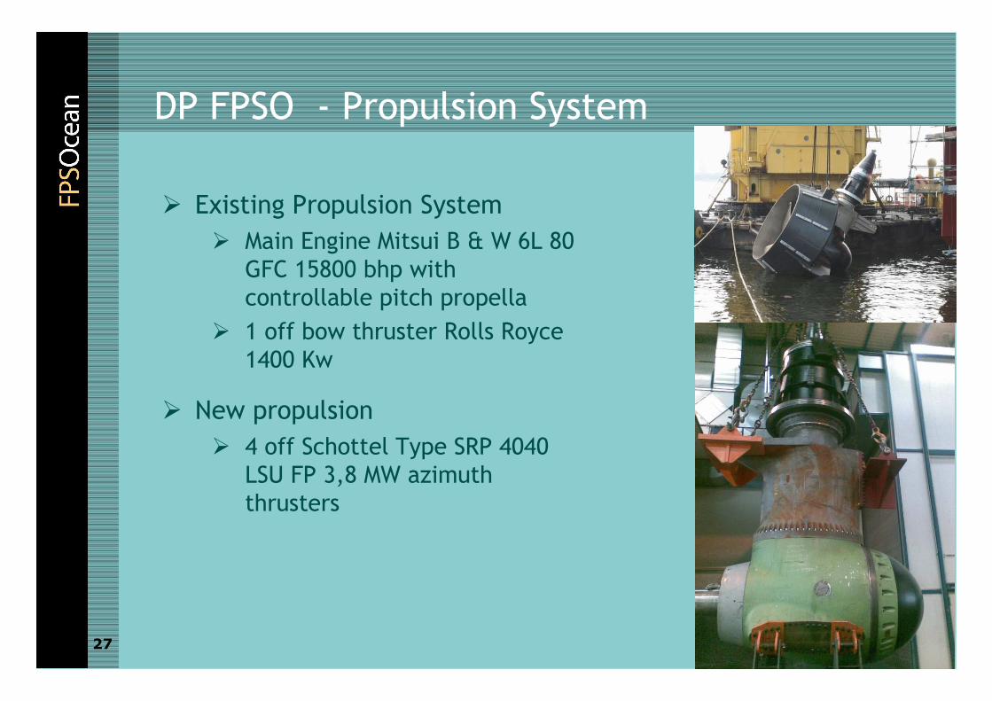
DP FPSO - Propulsion System
� Existing Propulsion System
� Main Engine Mitsui B & W 6L 80
GFC 15800 bhp with
controllable pitch propella
� 1 off bow thruster Rolls Royce
1400 Kw
� New propulsion
� 4 off Schottel Type SRP 4040
LSU FP 3,8 MW azimuth
thrusters
27

28
DP FPSO - Power Generation
� Shaft alt 1 x 1688 KW (existing)
� 2 off Siemens SGT 500 17 MW dual fuel gas turbine generators
� In normal operations, the gas turbines are fired by associated gas
from the produced oil. In case of process or gas compression
shutdown, the gas turbines will switch to MDO within one minute
without loss of power. Heavy fuel oil (HFO) operation is optional.

DP FPSO - Siemens SGT 500
29
Robust dual fuel Gas Turbine power generation
�Proven design with high availability and
reliability
� Industrial light weight turbine
�Low maintenance and operation cost
�Nominally 5 years between overhauls
�Fuel flexibility
� Gas, marine diesel and heavy fuel oil and
crude

Project Status – HSE Statistic
30
DD
Man-hours Sub Con
Man-hours Total
Man-hours Hazards Spotted
First Aid
Minor
LTI
Fire
Dama
ge
Near Miss
Heat Stress
Last week
24,435 11,620 36,055 11 1 0 0 0 0 0 0
Cumulative
1,056,776 143,680 1,200,456 358 7 6 1 0 0 0 0
HSE Report Cumulated
Near Misses 0
No. of Fatalities 0
No. of injuries 0
Medical Treatment Cases 0
First Aid Cases 13
No. of lost time injuries 0
Hours Worked 307348
Lost Time Injury Frequency Rate 0
SOAP Cards 17
Lamprell
Drydocks World Dubai (end of April 2008)
Lamprell (work scope completed end February 2008)

Project Status – Vessel Integration
31
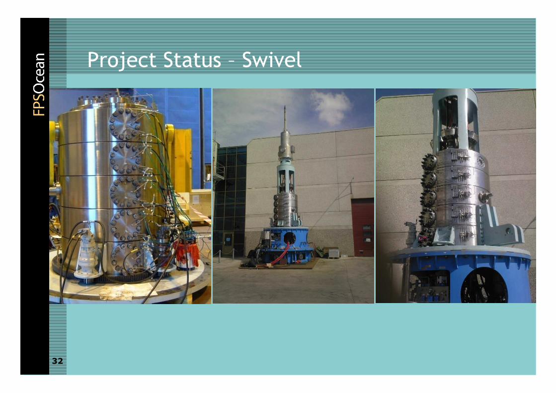
Project Status – Swivel
32

Project Status – Mechanical Equipment

34
Conclusions
� An flexible Dynamically Positioned FPSO facility has been
developed
� The generic design will allow the DeeP Producer 1 to operated at
the majority of new deep water field
� The innovative Disconnectable Riser Buoy™ ensure that multible
risers can be accomodated and it warrant the viability of the
dynamically positioned FPSO
� Conversion are well underway and the DeeP Producer 1 will be
able to start producing late 2008 early 2009

35
Thank You For Your Attention
Laurita
Semakau Spirit