Downloaded from ...EIA-557 - Statistical Process Control Systems. EIA-364-20 - Withstanding Voltage...
26
INCH-POUND MIL-DTL-83513F 22 March 2007 SUPERSEDING MIL-DTL-83513E 29 May 2002 DETAIL SPECIFICATION CONNECTORS, ELECTRICAL, RECTANGULAR, MICROMINIATURE, POLARIZED SHELL, GENERAL SPECIFICATION FOR This specification is approved for use by all Departments and Agencies of the Department of Defense. 1. SCOPE 1.1 Scope . This specification covers polarized shell, microminiature, rectangular connectors. 1.2 Classification . 1.2.1 Classes . P - All plastic (shell and insulator) M - Metal shell (plastic insulator) 1.2.2 Types . I - Crimp contacts (nonremovable) II - Solder contacts (nonremovable) 2. APPLICABLE DOCUMENTS 2.1 General . The documents listed in this section are specified in sections 3, 4, or 5 of this specification. This section does not include documents cited in other sections of this specification or recommended for additional information or as examples. While every effort has been made to ensure the completeness of this list, document users are cautioned that they must meet all specified requirements documents cited in sections 3, 4, or 5 of this specification, whether or not they are listed. 2.2 Government documents . 2.2.1 Specifications, standards, and handbooks . The following specifications, standards, and handbooks form a part of this document to the extent specified herein. Unless otherwise specified, the issues of these documents are those cited in the solicitation or contract. Comments, suggestions, or questions on this document should be addressed to: Defense Supply Center, Columbus (DSCC-VAI), P.O. Box 3990, Columbus, OH 43218-3990 or email to [email protected] . Since contract information can change, you may want to verify the currency of this address information using the ASSIST Online database at http://assist.daps.mil. AMSC N/A FSC 5935 Downloaded from http://www.everyspec.com
Transcript of Downloaded from ...EIA-557 - Statistical Process Control Systems. EIA-364-20 - Withstanding Voltage...
INCH-POUND
MIL-DTL-83513F 22 March 2007SUPERSEDING MIL-DTL-83513E 29 May 2002
DETAIL SPECIFICATION
CONNECTORS, ELECTRICAL, RECTANGULAR,
MICROMINIATURE, POLARIZED SHELL, GENERAL SPECIFICATION FOR
This specification is approved for use by all Departments and Agencies of the Department of Defense.
1. SCOPE
1.1 Scope. This specification covers polarized shell, microminiature, rectangular connectors.
1.2 Classification.
1.2.1 Classes.
P - All plastic (shell and insulator) M - Metal shell (plastic insulator)
1.2.2 Types.
I - Crimp contacts (nonremovable) II - Solder contacts (nonremovable)
2. APPLICABLE DOCUMENTS
2.1 General. The documents listed in this section are specified in sections 3, 4, or 5 of this
specification. This section does not include documents cited in other sections of this specification or recommended for additional information or as examples. While every effort has been made to ensure the completeness of this list, document users are cautioned that they must meet all specified requirements documents cited in sections 3, 4, or 5 of this specification, whether or not they are listed.
2.2 Government documents.
2.2.1 Specifications, standards, and handbooks. The following specifications, standards, and handbooks form a part of this document to the extent specified herein. Unless otherwise specified, the issues of these documents are those cited in the solicitation or contract.
Comments, suggestions, or questions on this document should be addressed to: Defense Supply Center, Columbus (DSCC-VAI), P.O. Box 3990, Columbus, OH 43218-3990 or email to [email protected]. Since contract information can change, you may want to verify the currency of this address information using the ASSIST Online database at http://assist.daps.mil.
AMSC N/A FSC 5935
Downloaded from http://www.everyspec.com
MIL-DTL-83513F
2
COMMERCIAL ITEM DESCRIPTIONS
A-A-59551 - Wire, Electrical, Copper (Uninsulated). A-A-59588 - Rubber, Silicone.
DEPARTMENT OF DEFENSE SPECIFICATIONS
MIL-M-24519 - Molding Plastics, Electrical, Thermoplastic. MIL-DTL-83513/12 - Connectors, Electrical, Rectangular, Plug, Microminiature, Polarized
Shell, Right Angle, Pin Contacts, 4 Row, Solder Type, Narrow Profile, 100 Contacts, Printed Circuit BoardMIL-DTL-83513/15 -
MIL-DTL-83513/15 - Connectors, Electrical, Rectangular, Receptacle, Microminiature, Polarized Shell, Right Angle, Sockets Contacts, 4 Row, Solder Type, Narrow Profile, 100 Contacts, Printed Circuit Board
MIL-DTL-83513/18 - Connectors, Electrical, Rectangular, Plug, Microminiature, Polarized Shell, Right Angle, Pin Contacts, 4 Row, Solder Type, Standard Profile, 100 Contacts, Printed Circuit Board
MIL-DTL-83513/21 - Connectors, Electrical, Rectangular, Receptacle, Microminiature, Polarized Shell, Right Angle, Socket Contacts, 4 Row, Solder Type, Standard Profile, 100 Contacts, Printed Circuit Board
MIL-DTL-83513/24 - Connectors, Electrical, Rectangular, Plug, Microminiature, Polarized Shell, Straight, Pin Contacts, 4 Row, Solder Type, 100 Contacts, Printed Circuit Board
MIL-DTL-83513/27 - Connectors, Electrical, Rectangular, Receptacle, Microminiature, Polarized Shell, Straight, Socket Contacts, 4 Row, Solder Type, 100 Contacts, Printed Circuit Board
MIL-DTL-83513/30 - Connectors, Electrical, Rectangular, Plug, Microminiature, Polarized Shell, Straight, Pin Contacts, 4 Row, Solder Type, Standard Profile, 100 Contacts, Printed Circuit Board
MIL-DTL-83513/33 - Connectors, Electrical, Rectangular, Receptacle, Microminiature, Polarized Shell, Straight, Socket Contacts, 4 Row, Solder Type, Standard Profile, 100 Contacts, Printed Circuit Board
(See Supplement 1 for list of associated specifications).
FEDERAL STANDARD
FED-STD-H28 - Screw Thread Standards for Federal Services.
DEPARTMENT OF DEFENSE STANDARDS
MIL-STD-202 - Test Methods for Electronic and Electrical Component Parts. MIL-STD-681 - Identification Coding and Application of Hookup and Lead Wire. MIL-STD-790 - Reliability Assurance Program for Electronic Parts Specifications. MIL-STD-810 - Environmental Engineering Considerations and Laboratory Tests. MIL-STD-889 - Dissimilar Metals MIL-STD-1285 - Marking of Electrical and Electronic Parts.
(Copies of these documents are available online at http://assist.daps.dla.mil/quicksearch/ or
http://assist.daps.dla.mil or from the Standardization Documents Order Desk, 700 Robbins Avenue, Bldg. 4D, Philadelphia, PA 19111-5094.)
Downloaded from http://www.everyspec.com
MIL-DTL-83513F
3
2.2.2 Other Government documents, drawings and publications. The following other Government documents, drawings and publications form a part of this document to the extent specified herein. Unless otherwise specified, the issues of these documents are those cited in the solicitation or contract (see 6.2).
NATIONAL AERONAUTICS AND SPACE ADMINISTRATION (NASA)
JSC SP-R-0022 - Vacuum Stability Requirements of Polymeric Material for Spacecraft Applications.
(Copies of these documents are available online at www.nasa.gov/centers/johnson/home/ or the NASA
Johnson Space Center 2101 NASA Parkway Houston, Texas 77058.)
DEFENSE SUPPLY CENTER COLUMBUS (DSCC)
04035 - Wire, Electrical, Composite, Polytetraflouroethylene/Polyimide insulated, Light Weight, Silver Coated, High Strength or Ultra High Strength Copper Alloy, 200°C, 600 Volt
(Copies of these documents are available online at http://www.dscc.dla.mil/Programs/MilSpec/ or from
the Defense Supply Center Columbus, ATTN: VAI, P.O. Box 3990, Columbus, OH 43218-3990.)
2.3 Non-Government publications. The following documents form a part of this document to the extent specified herein. Unless otherwise specified, the issues of these documents are those cited in the solicitation or contract (see 6.2).
ASME INTERNATIONAL
ASME Y-14.5 - Dimensioning and Tolerancing.
(Copies of these documents are available online at http://www.asme.org or from the ASME International, Three Park Avenue, New York, NY 10016-5990.) ASTM INTERNATIONAL
ASTM A342/A342M - Standard Test Method for Permeability of Materials Feebly Magnetic ASTM A693 - Precipitation Hardening Stainless and Heat Resisting Steel Plate, Sheet,
and Strip. ASTM B85 - Aluminum-Alloy Die Castings, Standard Specification for. ASTM B221 - Aluminum and Aluminum Alloy Extruded Bars, Rods, Wire, Profiles and
Tubes. ASTM B488 - Gold for Engineering Uses, Electrodeposited Coatings of. ASTM B733 - Metal, Autocatylitic Electroless Nickel-Phosphorous Coatings on. ASTM D4067 - Standard Classification System for Reinforced and Filled Poly(Phenylene
Sulfide) (PPS) Injection Molding and Extrusion Materials Using ASTM Methods
ASTM D5138 - Liquid Crystal Polymers, Standard Specification for. ASTM D5927 - Thermoplastic Polyester (TPES) Injection and Extrusion Materials Based
on ISO Test methods, Standard Specification for. ASTM D5948 - Compounds Molding, Thermosetting. ASTM E595 - Material from Outgassing in a Vacuum Environment, Total Mass Loss
and Collected Volatile Condensable, Standard Test Method for.
Downloaded from http://www.everyspec.com
MIL-DTL-83513F
4
Copies of these documents are available online at http://www.astm.org or from the ASTM International, P.O. Box C700, 100 Barr Harbor Drive, West Conshohocken, PA 19428-2959.)ELECTRONIC INDUSTRIES ASSOCIATION (EIA)
EIA-557 - Statistical Process Control Systems. EIA-364-20 - Withstanding Voltage Test Procedure for Electrical Connectors, Sockets
and Coaxial Contacts EIA-364-21 - Insulation Resistance Test Procedures for Electrical Connectors,
Sockets, and Coaxial Contacts EIA-364-23 - Low Level Contact Resistance Test Procedure for Electrical Connectors
and Sockets EIA-364-26 - Salt Spray Test Procedure for Electrical Connectors, Contacts and
Sockets EIA-364-27 - Mechanical Shock (Specified Pulse) Test Procedure for Electrical
Connectors EIA-364-28 - Vibration Test Procedure for Electrical Connectors and Sockets EIA-364-29 - Contact Retention Test Procedure for Electrical Connectors EIA-364-31 - Humidity Test Procedure for Electrical Connectors and Sockets EIA-364-32 - Thermal Shock (Temperature Cycling) Test Procedure for Electrical
Connectors and Sockets
(Copies of these documents are available online at http://www.eia.org or from the Electronic Industries Alliance, Engineering Department, 2500 Wilson Boulevard, Arlington, VA 22201.) INTERNATIONAL ORGANIZATION FOR STANDARDS (ISO)
ISO 10012-1 - Equipment, Quality Assurance Requirements for Measuring, Part 1: Meteorological Confirmation System for Measuring Equipment.
(Copies of these documents are available online at http://www.iso.ch or from the International
Organization for Standardization American National Standards Institute, 11 West 42nd Street, 13th Floor, New York, NY 10036.)
IPC - ASSOCIATION CONNECTING ELECTRONICS INDUSTRIES
J-STD-004 - Requirements for Solder Fluxes J-STD-005 - Requirements for Solder Paste J-STD-006 - Requirements for Electronic Grade Solder Alloys, Fluxed and Non
Fluxed Solid Solders for Electronic soldering applications.
(Copies of these documents are available online at http://www.ipc.org or from the IPC - Association Connecting Electronics Industries, 3000 Lakeside Drive, Suite 309 S, Bannockburn, IL 60015-1249.)
NCSL INTERNATIONAL
NCSL Z540.1 - Calibration Laboratories and Measuring and Test equipment, General Requirements.
(Copies of these documents are available online at http://www.ncsli.org or from NCSL International
2995 Wilderness Place, Suite 107 Boulder, Colorado 80301-5404)
Downloaded from http://www.everyspec.com
MIL-DTL-83513F
5
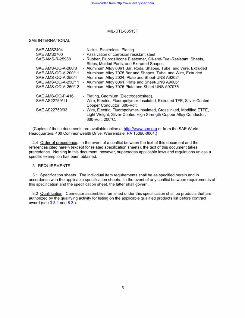
SAE INTERNATIONAL
SAE AMS2404 - Nickel, Electroless, Plating SAE AMS2700 - Passivation of corrosion resistant steel SAE-AMS-R-25988 - Rubber, Fluorosilicone Elastomer, Oil-and-Fuel-Resistant, Sheets,
Strips, Molded Parts, and Extruded Shapes SAE AMS-QQ-A-200/8 - Aluminum Alloy 6061 Bar, Rods, Shapes, Tube, and Wire, Extruded SAE AMS-QQ-A-200/11 - Aluminum Alloy 7075 Bar and Shapes, Tube, and Wire, Extruded SAE AMS-QQ-A-250/4 - Aluminum Alloy 2024, Plate and Sheet-UNS A92024 SAE AMS-QQ-A-250/11 - Aluminum Alloy 6061, Plate and Sheet-UNS A96061 SAE AMS-QQ-A-250/12 - Aluminum Alloy 7075 Plate and Sheet-UNS A97075
SAE AMS-QQ-P-416 - Plating, Cadmium (Electrodeposited). SAE AS22759/11 - Wire, Electric, Fluoropolymer-Insulated, Extruded TFE, Silver-Coated
Copper Conductor, 600-Volt. SAE AS22759/33 - Wire, Electric, Fluoropolymer-Insulated, Crosslinked, Modified ETFE,
Light Weight, Silver-Coated High Strength Copper Alloy Conductor, 600-Volt, 200!C.
(Copies of these documents are available online at http://www.sae.org or from the SAE World
Headquarters, 400 Commonwealth Drive, Warrendale, PA 15096-0001.) 2.4 Order of precedence. In the event of a conflict between the text of this document and the
references cited herein (except for related specification sheets), the text of this document takes precedence. Nothing in this document, however, supersedes applicable laws and regulations unless a specific exemption has been obtained.
3. REQUIREMENTS
3.1 Specification sheets. The individual item requirements shall be as specified herein and in accordance with the applicable specification sheets. In the event of any conflict between requirements of this specification and the specification sheet, the latter shall govern.
3.2 Qualification. Connector assemblies furnished under this specification shall be products that are authorized by the qualifying activity for listing on the applicable qualified products list before contract award (see 3.3.1 and 6.3 ).
Downloaded from http://www.everyspec.com
MIL-DTL-83513F
6
3.2.1 Quality.
3.2.1.1 Statistical process control (SPC). The contractor shall implement and use statistical process control techniques in the manufacturing process for parts covered by this specification. The SPC program shall be developed and maintained in accordance with EIA-557. Where SPC cannot be utilized because of non-continuous production requirements, a lot sampling plan for inspection in accordance with table IX with c = 0 can be utilized. The SPC and c = 0 programs shall be documented and maintained as part of the overall reliability assurance program in accordance with EIA-557 and MIL-STD-790. Evidence of such compliance shall be verified by the qualifying activity of this specification as a prerequisite for qualification. Dimensioning and tolerancing shall be in accordance with ASME Y-14.5.
3.3 Materials. Materials shall be as identified herein or as approved by the qualifying activity. However, when a definite material is not specified, a material shall be used which will enable the connectors to meet the performance requirements of this specification. Acceptance or approval of any constituent material shall not be construed as a guarantee of acceptance of the finished product.
3.3.1 Interface, materials, platings and processes. The interface, materials, platings, and processes identified in this specification have been identified to assure that connectors manufactured to this specification will properly interface to similar industry standard or government specified connector systems without problems of electrochemical contamination or excessive mechanical wear. The manufacturers of connectors supplied to this specification are allowed to use industry standard materials, platings, and processes other than those identified in 3.3. The use of alternate materials, platings and processes must be coordinated with the qualifying activity as part of the qualification process. The use of alternate materials, plating, and processes must not result in inferior short or long term performance or reliability of these connectors as compared with connectors manufactured using the referenced materials, platings, or processes described in this specification. Short or long term failures or reliability problems due to use of these alternate materials or processes shall be the responsibility of the supplier.
3.3.1.1 Recycled, recovered, or environmentally preferable materials. Recycled, recovered, or environmentally preferable materials should be used to the maximum extent possible provided that the material meets or exceeds the operational and maintenance requirements, and promotes economically advantageous life cycle costs.
3.3.2 Dissimilar metals. When dissimilar metals are used in intimate contact with each other, protection against electrolytic corrosion shall be provided. Dissimilar metals such as brass, copper or steel (except corrosion-resisting steel passivated in accordance with SAE-AMS2700) (see 3.3.1 ) shall not be used in intimate contact with aluminum or aluminum alloy without protective measures for dissimilar metals in accordance with MIL-STD-889.
3.3.3 Nonmagnetic materials. All parts used shall be made from materials which are classed as nonmagnetic (see 3.5.1 ).
3.3.4 Contact materials. Contacts shall be made of suitably conductive copper based alloys. All contacts shall be suitably protected from corrosion.
3.3.5 Contact plating. Contacts shall be gold plated in accordance with ASTM B488, type II, class 1.27 (50 micro inches minimum), code C over suitable underplate. Silver underplating shall not be used.
Downloaded from http://www.everyspec.com

MIL-DTL-83513F
7
3.3.6 Dielectric materials.
3.3.6.1 Inserts, class M. Inserts for class M connector material shall conform to the requirements of type GDI-30F or type SDG-F in accordance with ASTM D5948, or shall be glass filled thermoplastic materials in accordance with ASTM D5927 or MIL-M-24519 (color optional) or Liquid Crystal Polymer (LCP) in accordance with ASTM D5138, color optional..
3.3.6.2 Inserts, class P. All plastic class P connectors shall conform to the requirements of type GDI-30F or SDG-F in accordance with ASTM D 5948, or types TPES102G30, TPES013G30, TPES023G30, in accordance with ASTM D5927, or GPT-30F, GET-30F, and GCT-30F in accordance with MIL-M-24519 or PPS000G40A30330E1F01Y11 in accordance with ASTM D4067, or GST-40F in accordance with MIL-M-24519, or LCP0120G30A43430 EA300ED035EE200EF140 or LCP0120G50A44230 EA300ED042EE200EF180 in accordance with ASTM D5138, or GLCP-30F or GLCP-50 in accordance with MIL-M-24519 (color optional).
3.3.7 Shells. Shells shall be die cast or extruded aluminum type A380 in accordance with ASTM B85, or bar stock aluminum in accordance with ASTM B 221, or aluminum alloy 2024 in accordance with SAE-AMS-QQ-A-250/4 or 6061, in accordance with SAE-AMS-QQ-A-200/8 or SAE-AMS-QQ-A-250/11 or 7075 in accordance with SAE-AMS-QQ-A-200/11 or SAE-AMS-QQ-A-250/12 or 300 series stainless steel passivated in accordance with SAE-AMS-2700, type 2.
3.3.7.1 Finish (class M). Cadmium plated in accordance with SAE-AMS-QQ-P-416, type II, class 3. A suitable underplate is permissible for aluminum shells when cadmium plating is used. Shells shall be electroless nickel-plated, in accordance with SAE AMS2404, class 3 or 4, .0005 inch minimum thickness or ASTM B733, class 3 or 4, service code SC2 for space applications only.
3.3.8 Fungus resistant. Materials used in the construction of these connectors shall be fungus inert (see 4.2.5 ).
3.3.9 Interfacial seals. Seals shall be made from silicone or fluorosilicone elastomer in accordance with A-A-59588 or SAE-AMS-R-25988.
3.3.10 Flux. When flux is used, it shall conform to type RMA flux, soldering liquid, (rosin base) in accordance with J-STD-004, J-STD-005, or J-STD-006.
3.3.11 Pure tin. The use of pure tin is prohibited. Tin content used in connector materials shall not exceed 97 percent, and an alloy material shall be chosen to inhibit the growth of tin whiskers (see 6.4 ).
3.4 Design, construction, and physical dimensions. Connectors shall be of the design, construction and physical dimensions specified (see 3.1). Connectors shall be so designed that neither the pins nor the sockets will be damaged during normal mating of counterpart connectors.
3.4.1 Contact design. Contacts shall be the reverse gender type. The live pin shall be installed in a protective insulator with the static socket protruding from a suitably shrouded insulator.
3.4.1.1 Solder contacts. Solder contacts shall be nonremovable from the insert and shall have solder cup terminals as specified (see 3.1). Solder cups shall be so designed that during soldering no components shall be damaged and no liquid solder shall escape.
3.4.1.2 Crimp contacts. Crimp contacts shall be nonremovable from the insert.
3.4.1.3 Contact identification. Contact position number one shall have an identifiable mark placed on the surface or side of the number one contact position.
Downloaded from http://www.everyspec.com
MIL-DTL-83513F
8
3.4.2 Insert design and construction. Inserts shall be designed with suitable sections and radii such that they will not readily chip, crack, or break in assembly or in normal service. Inserts shall be molded in or bonded into the metal shell (class M) or as specified (see 3.1). Pin inserts shall provide adequate protection against a socket contacting a pin before the mating pair of connectors has been polarized. The insert shall be so designed that the insert cannot be removed from the shells (class M) in accordance with the retention requirement of 3.5.17. The contact retention system shall provide positive retention.
3.4.2.1 Insert arrangement. The contact arrangement shall be as specified by the connector Part or Identifying Number (PIN) (see 3.1).
3.4.2.2 Contact alignment and stability. With all contacts in place, the alignment of pin/socket contacts shall always permit engagement irrespective of buildup of allowable tolerances on hole locations, distortion of contacts due to crimping, and insulator location in the shell.
3.4.3 Shell design (class M). The shell shall be designed to positively retain the insulator and shall be constructed so that the insulator cannot be removed (see 3.4.2).
3.4.3.1 Shell polarization. Polarization shall be accomplished by a keystone shape shell design with polarization accomplished before engagement of the pins and sockets.
3.4.3.2 Mounting hardware (see MI-DTL-83513/5 for mounting hardware options). Hardware shall conform to ASTM A693, SAE AMS2700, type 2, and FED-STD-H28 (see 3.1). Mounting hardware is to be ordered independently of connectors and shall be supplied loose pack unless otherwise specified.
3.4.4 Interchangeability. All connectors and accessories having the same military PIN shall be completely interchangeable with each other with respect to installation (physical), performance (function) and intermateability, as specified herein. Solder and crimp contact connectors shall be intermatable (see 3.1).
3.4.5 Pigtail wire. Insulated wire shall be in accordance with SAE AS22759/11, DSCC Drawing 04035, SAE AS22759/33, except SAE AS22759/33 is acceptable for space applications. (Note: Corrosion has been experienced with connectors that are prewired in accordance with SAE AS22759/33 and stored in a sealed environment. This should be considered when using, packaging and storing connectors using this wire. There are no established industry standards for test procedures or acceptable outgas product levels for these wires). Uninsulated wire shall be in accordance with A-A-59551, except shall be gold plated or tin-lead plated with a minimum of 3 percent lead in accordance with the individual specification sheet.
3.5 Performance. Connectors shall be designed to meet the performance requirements specified herein.
3.5.1 Magnetic permeability. The relative permeability shall not exceed 2.0 " when measured as specified in 4.5.3, except for hardware, see 3.1.
3.5.2 Mating and unmating force. The maximum mating and unmating force shall not exceed a value equal to 10 ounces times the number of contacts. Testing shall be as specified in 4.5.4.
3.5.3 Contact retention. Contacts for connectors shall be retained in the insulators by a 5-pound minimum force as specified in 4.5.5.
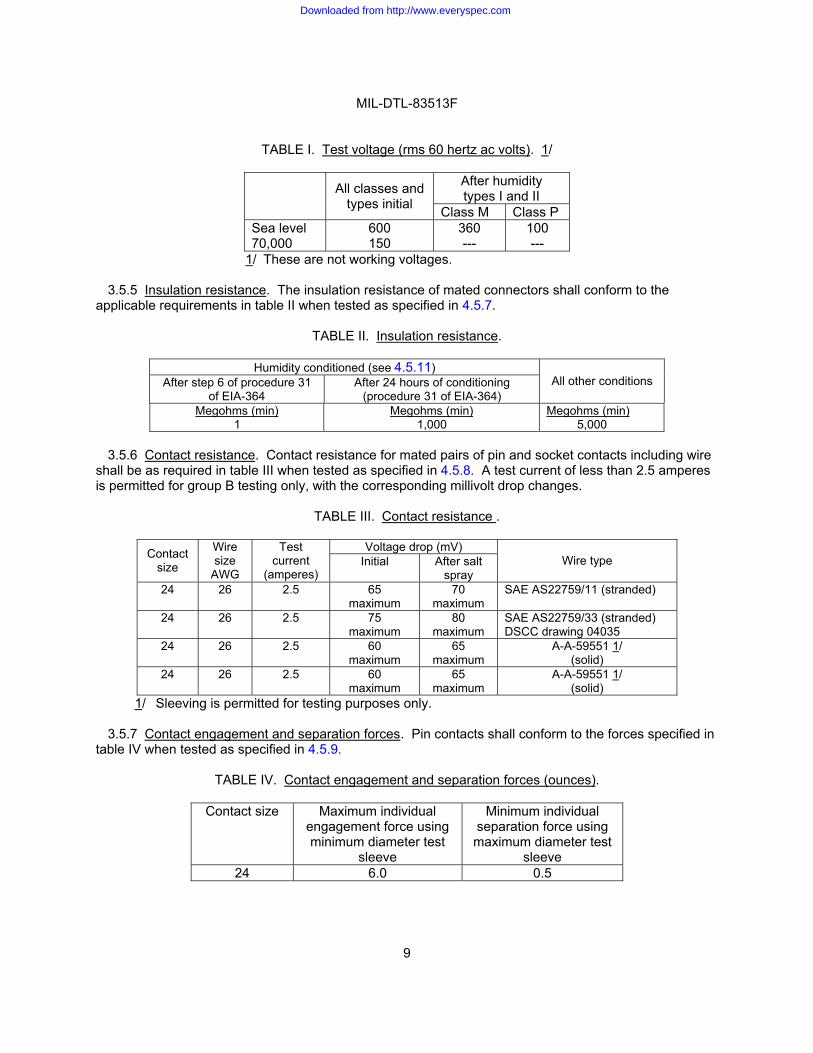
3.5.4 Dielectric withstanding voltage. Mated or unmated connectors shall show no evidence of breakdown or flashover when subjected to the test voltages and altitude in table I. Corona shall not be considered as specified in 4.5.6.
Downloaded from http://www.everyspec.com
MIL-DTL-83513F
9
TABLE I. Test voltage (rms 60 hertz ac volts). 1/
After humidity types I and II
All classes and types initial Class M Class P
Sea level 70,000
600 150
360 ---
100 ---
1/ These are not working voltages.
3.5.5 Insulation resistance. The insulation resistance of mated connectors shall conform to the applicable requirements in table II when tested as specified in 4.5.7.
TABLE II. Insulation resistance.
Humidity conditioned (see 4.5.11) After step 6 of procedure 31
of EIA-364 After 24 hours of conditioning
(procedure 31 of EIA-364) All other conditions
Megohms (min) 1
Megohms (min) 1,000
Megohms (min) 5,000
3.5.6 Contact resistance. Contact resistance for mated pairs of pin and socket contacts including wire
shall be as required in table III when tested as specified in 4.5.8. A test current of less than 2.5 amperes is permitted for group B testing only, with the corresponding millivolt drop changes.
TABLE III. Contact resistance .
Voltage drop (mV) Contact size
Wire size
AWG
Test current
(amperes) Initial After salt
spray Wire type
24 26 2.5 65 maximum
70 maximum
SAE AS22759/11 (stranded)
24 26 2.5 75 maximum
80 maximum
SAE AS22759/33 (stranded) DSCC drawing 04035
24 26 2.5 60 maximum
65 maximum
A-A-59551 1/ (solid)
24 26 2.5 60 maximum
65 maximum
A-A-59551 1/ (solid)
1/ Sleeving is permitted for testing purposes only.
3.5.7 Contact engagement and separation forces. Pin contacts shall conform to the forces specified in table IV when tested as specified in 4.5.9.
TABLE IV. Contact engagement and separation forces (ounces).
Contact size Maximum individual engagement force using minimum diameter test
sleeve
Minimum individual separation force using maximum diameter test
sleeve 24 6.0 0.5
Downloaded from http://www.everyspec.com
MIL-DTL-83513F
10
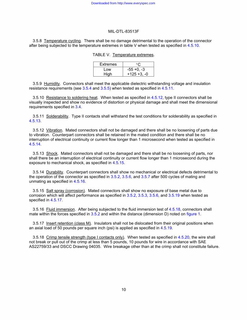
3.5.8 Temperature cycling. There shall be no damage detrimental to the operation of the connector after being subjected to the temperature extremes in table V when tested as specified in 4.5.10.
TABLE V. Temperature extremes.
Extremes !C Low High
-55 +0, -3 +125 +3, -0
3.5.9 Humidity. Connectors shall meet the applicable dielectric withstanding voltage and insulation
resistance requirements (see 3.5.4 and 3.5.5) when tested as specified in 4.5.11.
3.5.10 Resistance to soldering heat. When tested as specified in 4.5.12, type II connectors shall be visually inspected and show no evidence of distortion or physical damage and shall meet the dimensional requirements specified in 3.4.
3.5.11 Solderability. Type II contacts shall withstand the test conditions for solderability as specified in 4.5.13.
3.5.12 Vibration. Mated connectors shall not be damaged and there shall be no loosening of parts due to vibration. Counterpart connectors shall be retained in the mated condition and there shall be no interruption of electrical continuity or current flow longer than 1 microsecond when tested as specified in 4.5.14.
3.5.13 Shock. Mated connectors shall not be damaged and there shall be no loosening of parts, nor
shall there be an interruption of electrical continuity or current flow longer than 1 microsecond during the exposure to mechanical shock, as specified in 4.5.15.
3.5.14 Durability. Counterpart connectors shall show no mechanical or electrical defects detrimental to the operation of the connector as specified in 3.5.2, 3.5.6, and 3.5.7 after 500 cycles of mating and unmating as specified in 4.5.16.
3.5.15 Salt spray (corrosion). Mated connectors shall show no exposure of base metal due to corrosion which will affect performance as specified in 3.5.2, 3.5.3, 3.5.6, and 3.5.19 when tested as specified in 4.5.17.
3.5.16 Fluid immersion. After being subjected to the fluid immersion test of 4.5.18, connectors shall
mate within the forces specified in 3.5.2 and within the distance (dimension D) noted on figure 1.
3.5.17 Insert retention (class M). Insulators shall not be dislocated from their original positions when an axial load of 50 pounds per square inch (psi) is applied as specified in 4.5.19.
3.5.18 Crimp tensile strength (type I contacts only). When tested as specified in 4.5.20, the wire shall
not break or pull out of the crimp at less than 5 pounds, 10 pounds for wire in accordance with SAE AS22759/33 and DSCC Drawing 04035. Wire breakage other than at the crimp shall not constitute failure.
Downloaded from http://www.everyspec.com
MIL-DTL-83513F
11
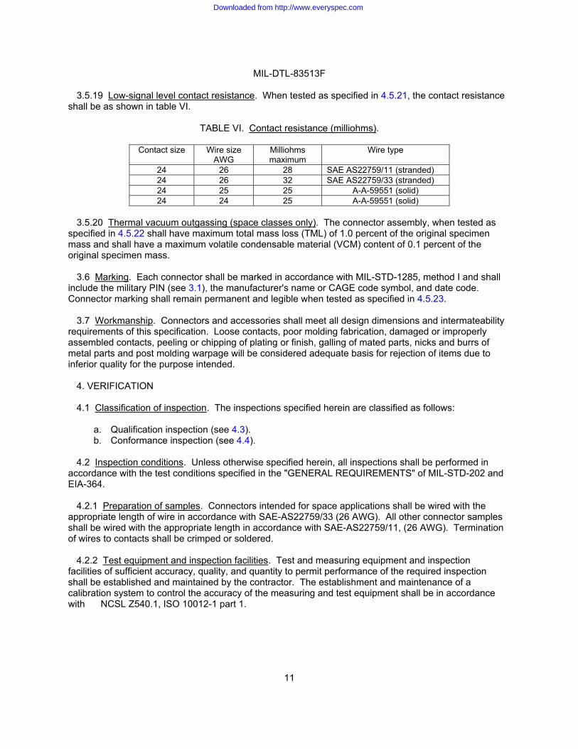
3.5.19 Low-signal level contact resistance. When tested as specified in 4.5.21, the contact resistance shall be as shown in table VI.
TABLE VI. Contact resistance (milliohms).
Contact size Wire size AWG
Milliohms maximum
Wire type
24 26 28 SAE AS22759/11 (stranded) 24 26 32 SAE AS22759/33 (stranded) 24 25 25 A-A-59551 (solid) 24 24 25 A-A-59551 (solid)
3.5.20 Thermal vacuum outgassing (space classes only). The connector assembly, when tested as
specified in 4.5.22 shall have maximum total mass loss (TML) of 1.0 percent of the original specimen mass and shall have a maximum volatile condensable material (VCM) content of 0.1 percent of the original specimen mass.
3.6 Marking. Each connector shall be marked in accordance with MIL-STD-1285, method I and shall
include the military PIN (see 3.1), the manufacturer's name or CAGE code symbol, and date code. Connector marking shall remain permanent and legible when tested as specified in 4.5.23.
3.7 Workmanship. Connectors and accessories shall meet all design dimensions and intermateability requirements of this specification. Loose contacts, poor molding fabrication, damaged or improperly assembled contacts, peeling or chipping of plating or finish, galling of mated parts, nicks and burrs of metal parts and post molding warpage will be considered adequate basis for rejection of items due to inferior quality for the purpose intended.
4. VERIFICATION
4.1 Classification of inspection. The inspections specified herein are classified as follows:
a. Qualification inspection (see 4.3). b. Conformance inspection (see 4.4).
4.2 Inspection conditions. Unless otherwise specified herein, all inspections shall be performed in
accordance with the test conditions specified in the "GENERAL REQUIREMENTS" of MIL-STD-202 and EIA-364.
4.2.1 Preparation of samples. Connectors intended for space applications shall be wired with the appropriate length of wire in accordance with SAE-AS22759/33 (26 AWG). All other connector samples shall be wired with the appropriate length in accordance with SAE-AS22759/11, (26 AWG). Termination of wires to contacts shall be crimped or soldered.
4.2.2 Test equipment and inspection facilities. Test and measuring equipment and inspection
facilities of sufficient accuracy, quality, and quantity to permit performance of the required inspection shall be established and maintained by the contractor. The establishment and maintenance of a calibration system to control the accuracy of the measuring and test equipment shall be in accordance with NCSL Z540.1, ISO 10012-1 part 1.
Downloaded from http://www.everyspec.com
MIL-DTL-83513F
12
4.2.3 Assembly plants. Assembly plants must be listed on or approved for listing on the applicable qualified products list. The qualified connector manufacturer shall certify that the assembly plant is approved for the distribution of the manufacturer's parts. The assembly plant shall use only piece parts supplied by the qualified connector manufacturer. No testing other than visual inspection is required on certified piece parts obtained from the qualified connector manufacturer, except when there is cause for rejection. All assemblies produced at the assembly plant shall be subjected to examination of product to assure that the assembly process conforms with that established at the qualified manufacturing plant. Quality control requirements, including government inspection surveillance, shall be the same as required for the qualified connector manufacturer.
4.2.4 Established reliability and high reliability practice . An established reliability and high reliability practice shall be established and maintained in accordance with MIL-STD-790. Evidence of such compliance shall be verified by the qualifying activity of this specification as a prerequisite for qualification and continued qualification.
4.2.5 Fungus resistance. Certification of method 508.5 of MIL-STD-810 is required (see 3.3.8).
4.3 Qualification inspection. Qualification inspection shall be performed at a laboratory acceptable to the Government (see 6.3) on sample units produced with equipment and procedures normally used in production. Use of alternate materials, platings and processes (see 3.3.1) shall be identified for inclusion in the product test documentation.
4.3.1 Sample size.
4.3.1.1 Connectors. To qualify all connector sizes, samples of the connectors with the largest number
of contacts for the class and type for which qualification is desired shall be inspected. If only one class is to be qualified, samples of six mated pairs of the largest size consisting of four samples of type I, and two samples of type II, shall be submitted. If both class P and M connectors are being qualified at the same time, samples of four mated pairs of the largest size in each class consisting of three samples of type I, and one sample of type II, shall be submitted. If qualification of only one type of any class is desired, samples of two mated pairs of each finish shall be submitted. For dielectric material, quantities and tests shall be determined by the qualification agency. If qualification of class M, nickel-plated connectors (intended for space using specified wire) is desired in addition to qualification of class P and M cadmium and nickel plated connectors, two additional mated pairs (one type I and one type II connector) of the largest size shall be submitted in addition to all other samples submitted. If the space application nickel plated connectors are submitted in addition to other test samples not including nickel plate, samples of four mated pairs of nickel plated connectors ( three of type I and one of type II) shall be submitted in addition to the other samples. In addition, four samples of type II (solid wire and solder cup) shall be tested to group V only specified in table VII.
4.3.1.2 Contacts. Individual contacts to be used in the connectors proposed for qualification shall be subject to crimp tensile strength testing in accordance with group IV specified in table VII. Twenty contact mating pairs for each wire type, shall be tested for qualification purposes and 10 contact mating pairs for each particular design shall be tested for retention of qualification (see 3.4.5).
4.3.1.3 Qualification of other connector sizes. For other connector sizes only, of both class P and M,
types I and II for which qualification is desired, two completely assembled type I mating connector pairs for each size and class shall be subjected to the tests specified in table VII. Successful qualification of type I connectors will qualify type II. If only qualification of one type is desired, only two each additional connectors of that type are to be submitted.
Downloaded from http://www.everyspec.com
MIL-DTL-83513F
13
4.3.2 Inspection routine. The samples shall be subjected to the inspections specified in table VII, in the order shown. All sample units shall be subjected to the inspections of group I. The sample shall then be divided equally into two groups; one shall be subjected to the group II inspections, and the other shall be subjected to the group III inspections. Group IV is for contacts only and the sample size shall be as specified in 4.3.1.2.
4.3.3 Failures. One or more failures shall be cause for refusal to grant qualification approval.
4.3.4 Verification of qualification. To retain qualification, the contractor shall verify in coordination with qualifying activity the capability of manufacturing products, which meet the performance requirements of this specification. Refer to the qualifying activity for the guidelines necessary to retain qualification to this specification. The contractor shall immediately notify the qualifying activity at any time that the inspection data indicates failure of the qualified product to meet the requirements of this specification.
Downloaded from http://www.everyspec.com
MIL-DTL-83513F
14
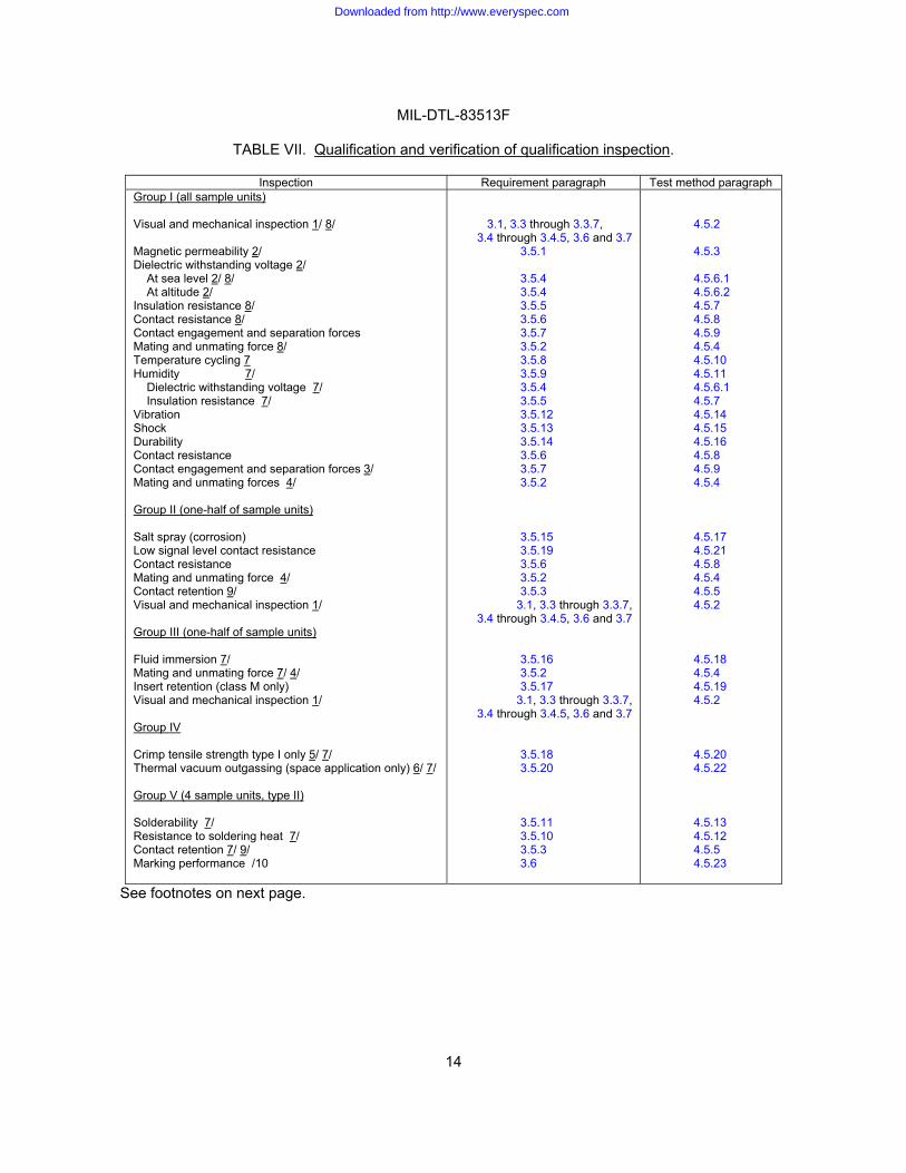
TABLE VII. Qualification and verification of qualification inspection.
Inspection Requirement paragraph Test method paragraph Group I (all sample units) Visual and mechanical inspection 1/ 8/ Magnetic permeability 2/ Dielectric withstanding voltage 2/
At sea level 2/ 8/ At altitude 2/
Insulation resistance 8/ Contact resistance 8/ Contact engagement and separation forces Mating and unmating force 8/ Temperature cycling 7Humidity 7/
Dielectric withstanding voltage 7/ Insulation resistance 7/
Vibration Shock Durability Contact resistance Contact engagement and separation forces 3/ Mating and unmating forces 4/ Group II (one-half of sample units) Salt spray (corrosion) Low signal level contact resistance Contact resistance Mating and unmating force 4/ Contact retention 9/ Visual and mechanical inspection 1/ Group III (one-half of sample units) Fluid immersion 7/ Mating and unmating force 7/ 4/ Insert retention (class M only) Visual and mechanical inspection 1/ Group IV Crimp tensile strength type I only 5/ 7/ Thermal vacuum outgassing (space application only) 6/ 7/ Group V (4 sample units, type II) Solderability 7/ Resistance to soldering heat 7/ Contact retention 7/ 9/ Marking performance /10
3.1, 3.3 through 3.3.7, 3.4 through 3.4.5, 3.6 and 3.7
3.5.1
3.5.4 3.5.4 3.5.5 3.5.6 3.5.73.5.2 3.5.8 3.5.9 3.5.4 3.5.5 3.5.12 3.5.133.5.14 3.5.6 3.5.7 3.5.2
3.5.15 3.5.19 3.5.6 3.5.2 3.5.3
3.1, 3.3 through 3.3.7, 3.4 through 3.4.5, 3.6 and 3.7
3.5.16 3.5.2 3.5.17
3.1, 3.3 through 3.3.7, 3.4 through 3.4.5, 3.6 and 3.7
3.5.183.5.20
3.5.11 3.5.10 3.5.3 3.6
4.5.2
4.5.3
4.5.6.1 4.5.6.2 4.5.7 4.5.8 4.5.94.5.4 4.5.10 4.5.11 4.5.6.1 4.5.7 4.5.14 4.5.15 4.5.16 4.5.8 4.5.9 4.5.4
4.5.17 4.5.21 4.5.8 4.5.4 4.5.5 4.5.2
4.5.18 4.5.4 4.5.19 4.5.2
4.5.20 4.5.22
4.5.13 4.5.12 4.5.5 4.5.23
See footnotes on next page.
Downloaded from http://www.everyspec.com
MIL-DTL-83513F
15
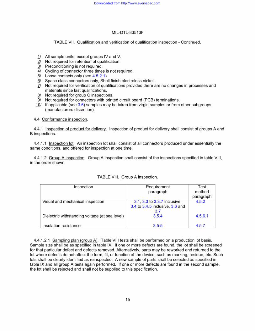
TABLE VII. Qualification and verification of qualification inspection - Continued.
1/ All sample units, except groups IV and V. 2/ Not required for retention of qualification. 3/ Preconditioning is not required. 4/ Cycling of connector three times is not required. 5/ Loose contacts only (see 4.5.2.1). 6/ Space class connectors only, Shell finish electroless nickel. 7/ Not required for verification of qualifications provided there are no changes in processes and
materials since last qualifications. 8/ Not required for group C inspections. 9/ Not required for connectors with printed circuit board (PCB) terminations.
10/ If applicable (see 3.6) samples may be taken from virgin samples or from other subgroups (manufacturers discretion).
4.4 Conformance inspection.
4.4.1 Inspection of product for delivery. Inspection of product for delivery shall consist of groups A and
B inspections.
4.4.1.1 Inspection lot. An inspection lot shall consist of all connectors produced under essentially the same conditions, and offered for inspection at one time.
4.4.1.2 Group A inspection. Group A inspection shall consist of the inspections specified in table VIII, in the order shown.
TABLE VIII. Group A inspection.
Inspection Requirement paragraph
Test method
paragraph Visual and mechanical inspection Dielectric withstanding voltage (at sea level) Insulation resistance
3.1, 3.3 to 3.3.7 inclusive, 3.4 to 3.4.5 inclusive, 3.6 and
3.7 3.5.4
3.5.5
4.5.2 4.5.6.1 4.5.7
4.4.1.2.1 Sampling plan (group A). Table VIII tests shall be performed on a production lot basis. Sample size shall be as specified in table IX. If one or more defects are found, the lot shall be screened for that particular defect and defects removed. Alternatively, parts may be reworked and returned to the lot where defects do not affect the form, fit, or function of the device, such as marking, residue, etc. Such lots shall be clearly identified as reinspected. A new sample of parts shall be selected as specified in table IX and all group A tests again performed. If one or more defects are found in the second sample, the lot shall be rejected and shall not be supplied to this specification.
Downloaded from http://www.everyspec.com

MIL-DTL-83513F
16
TABLE IX. Lot and sample size.
Lot size Visual and mechanical examination
2 to 13 14 to 150
151 to 280 281 to 500 501 to 1,200
1,201 to 3,200 3,201 to 10,000
10,001 to 35,000 35,001 to 150,000
150,001 to 500,000 500,001 and over
100% 13 20 29 34 42 50 60 74 90
102
4.4.1.3 Group B inspection. Group B inspection shall consist of the inspections specified in table X and shall be made on sample units randomly selected from inspection lots which have been subjected to and have passed the group A inspection.
TABLE X. Group B inspection.
Inspection Requirement paragraph
Test method paragraph
Contact resistance Mating and unmating force
3.5.6 3.5.2
4.5.8 4.5.4
4.4.1.3.1 Sampling plan. Table X tests shall be performed on a production lot basis. Sample size shall be as specified in table IX. If one or more defects are found, the lot shall be screened for that particular defect and defects removed. Alternatively, parts may be reworked and returned to the lot where defects do not affect the form, fit, or function of the device, such as marking, residue, etc. Such lots shall be clearly identified as reinspected. After screening and removal of defects, a new sample of parts shall be randomly selected and subjected to all tests in table X. If one or more defects are found in the second sample the lot shall be rejected and shall not be supplied to this specification.
4.4.1.3.2 Disposition of sample units. Sample units, which have passed all of group B inspection, may be delivered on the contract, if the lot is accepted.
4.4.2 Periodic inspection. Periodic inspection shall consist of group C inspection. Except where the results of these inspections show noncompliance with the applicable requirements (see 4.4.2.1.4), delivery of products which have passed groups A and B inspections shall not be delayed pending the results of these inspections.
4.4.2.1 Group C inspection. Group C inspection shall consist of the inspections specified in table VII, in the order shown. Group C inspection shall be made on sample units selected from inspection lots, which have passed the groups A and B inspections.
Downloaded from http://www.everyspec.com
MIL-DTL-83513F
17
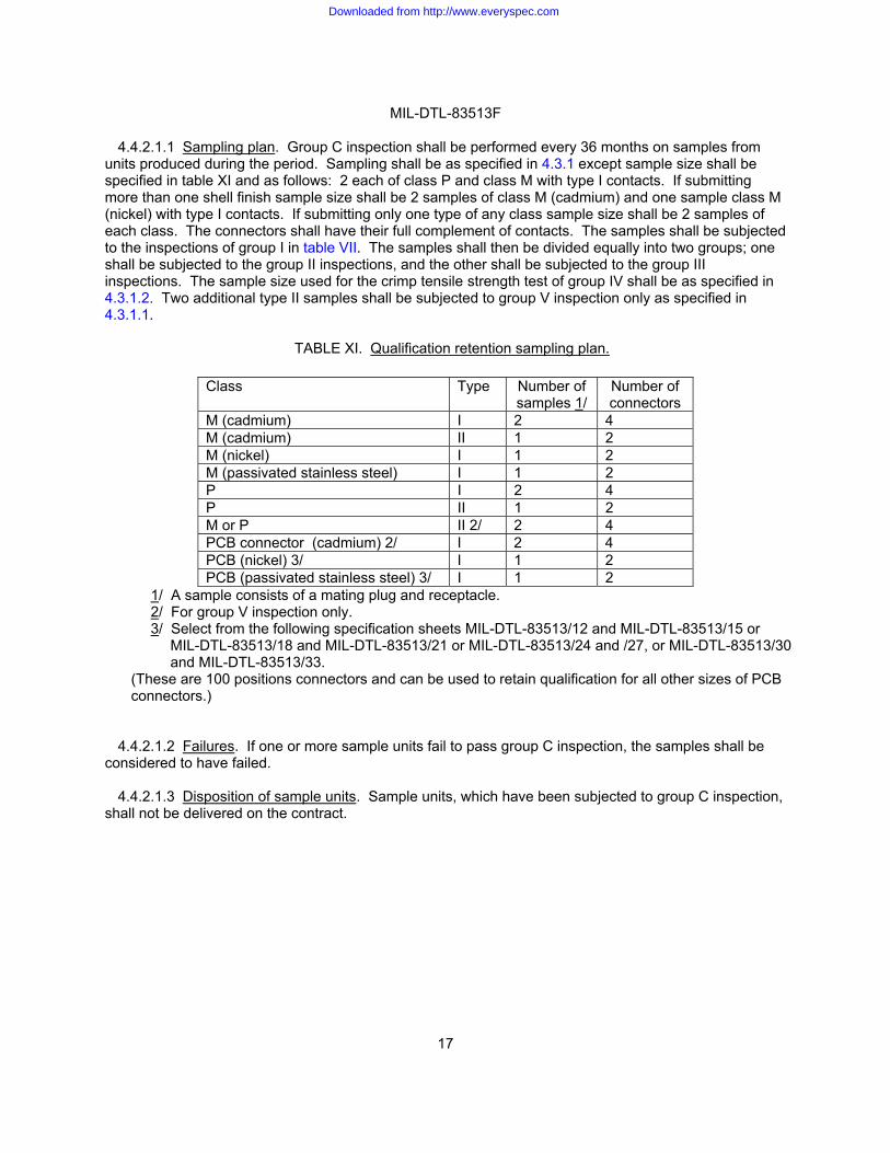
4.4.2.1.1 Sampling plan. Group C inspection shall be performed every 36 months on samples from units produced during the period. Sampling shall be as specified in 4.3.1 except sample size shall be specified in table XI and as follows: 2 each of class P and class M with type I contacts. If submitting more than one shell finish sample size shall be 2 samples of class M (cadmium) and one sample class M (nickel) with type I contacts. If submitting only one type of any class sample size shall be 2 samples of each class. The connectors shall have their full complement of contacts. The samples shall be subjected to the inspections of group I in table VII. The samples shall then be divided equally into two groups; one shall be subjected to the group II inspections, and the other shall be subjected to the group III inspections. The sample size used for the crimp tensile strength test of group IV shall be as specified in 4.3.1.2. Two additional type II samples shall be subjected to group V inspection only as specified in 4.3.1.1.
TABLE XI. Qualification retention sampling plan.
Class Type Number of
samples 1/ Number of connectors
M (cadmium) I 2 4 M (cadmium) II 1 2 M (nickel) I 1 2 M (passivated stainless steel) I 1 2 P I 2 4 P II 1 2 M or P II 2/ 2 4 PCB connector (cadmium) 2/ I 2 4 PCB (nickel) 3/ I 1 2 PCB (passivated stainless steel) 3/ I 1 2
1/ A sample consists of a mating plug and receptacle. 2/ For group V inspection only. 3/ Select from the following specification sheets MIL-DTL-83513/12 and MIL-DTL-83513/15 or
MIL-DTL-83513/18 and MIL-DTL-83513/21 or MIL-DTL-83513/24 and /27, or MIL-DTL-83513/30 and MIL-DTL-83513/33.
(These are 100 positions connectors and can be used to retain qualification for all other sizes of PCB connectors.)
4.4.2.1.2 Failures. If one or more sample units fail to pass group C inspection, the samples shall be considered to have failed.
4.4.2.1.3 Disposition of sample units. Sample units, which have been subjected to group C inspection, shall not be delivered on the contract.
Downloaded from http://www.everyspec.com

MIL-DTL-83513F
18
4.4.2.1.4 Noncompliance. If a sample fails to pass group C inspection, the manufacturer shall notify the qualifying activity and the cognizant inspection activity of such failure and take corrective action on the materials or processes, or both, as warranted, and on all units of product which can be corrected and which were manufactured under essentially the same materials and processes, and which are considered subject to the same failure. Acceptance of the product shall be discontinued until corrective action, acceptable to the qualifying activity has been taken. After the corrective action has been taken, group C inspection shall be repeated on additional sample units (all inspections, or the inspection which the original sample failed, at the option of the qualifying activity). Groups A and B inspections may be reinstituted; however, final acceptance and shipment shall be withheld until the group C inspection has shown that the corrective action was successful. In the event of failure after reinspection, information concerning the failure and corrective action shall be made available to the cognizant inspection activity and the qualifying activity.
4.5 Methods of inspection.
4.5.1 Test methods. The following tests and test methods assure connector integrity within typical operating conditions and applications. Alternate commercial industry standard test methods are allowed, however when and alternate method is used, the qualifying activity must be notified prior to performance of the test. The test methods described herein are proven methods and shall be the referee method in cases of dispute.
4.5.2 Visual and mechanical inspection. Contacts and connectors shall be examined to ensure conformance with this specification and the applicable detail documents not covered by the performance requirements specified in 3.5. In process controls of component parts, unrelated to lot sizes of finished connectors, may be utilized in lieu of examination of these components in the finished contacts or connectors to assure conformance of these component parts. Examination in a continuing manner shall be performed to assure compliance with the following requirements:
a. Specification sheets (3.1).
b. Materials (3.3 to 3.3.7, inclusive).
c. Design, construction and physical dimensions (3.4 to 3.4.5, inclusive).
d. Marking (3.6). e. Workmanship (3.7).
4.5.2.1 Final examination. Final examination of crimp contacts shall include a thorough examination to insure that the contact is free from mechanical defects, that there are no cracks around the crimp area, and that the contacts meet the physical requirements specified herein. Examination shall be made with a device having magnification power of approximately 3X.
4.5.3 Magnetic permeability. Permeability shall be measured on connectors with an instrument in accordance with ASTM A342/A342M. The connectors may be wired or unwired, but shall not be carrying current. Requirements shall be as specified in 3.5.1.
Downloaded from http://www.everyspec.com
MIL-DTL-83513F
19
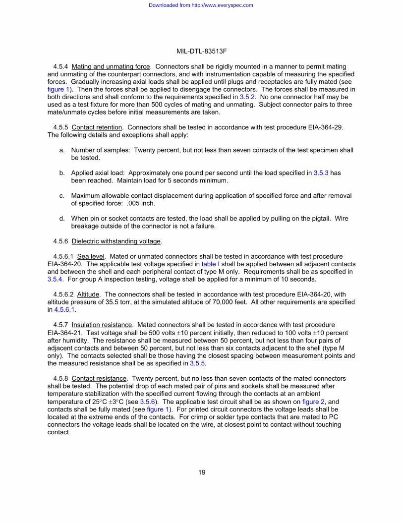
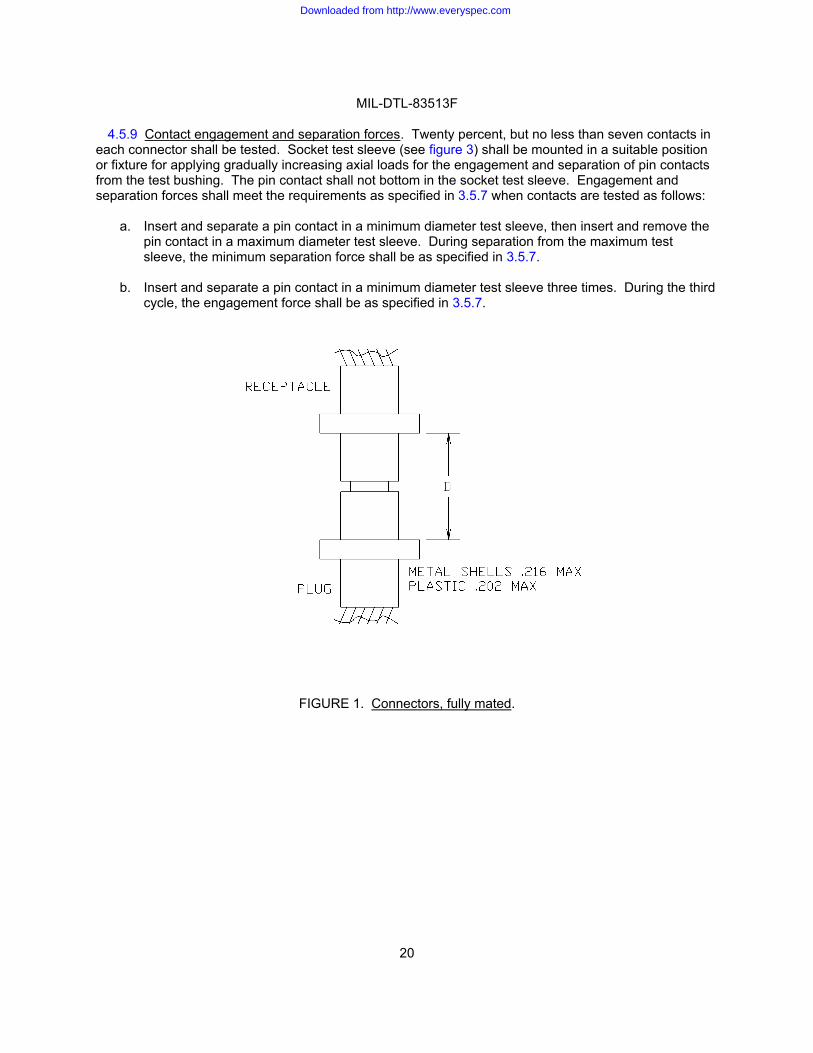
4.5.4 Mating and unmating force. Connectors shall be rigidly mounted in a manner to permit mating and unmating of the counterpart connectors, and with instrumentation capable of measuring the specified forces. Gradually increasing axial loads shall be applied until plugs and receptacles are fully mated (see figure 1). Then the forces shall be applied to disengage the connectors. The forces shall be measured in both directions and shall conform to the requirements specified in 3.5.2. No one connector half may be used as a test fixture for more than 500 cycles of mating and unmating. Subject connector pairs to three mate/unmate cycles before initial measurements are taken.
4.5.5 Contact retention. Connectors shall be tested in accordance with test procedure EIA-364-29. The following details and exceptions shall apply:
a. Number of samples: Twenty percent, but not less than seven contacts of the test specimen shall be tested.
b. Applied axial load: Approximately one pound per second until the load specified in 3.5.3 has
been reached. Maintain load for 5 seconds minimum.
c. Maximum allowable contact displacement during application of specified force and after removal of specified force: .005 inch.
d. When pin or socket contacts are tested, the load shall be applied by pulling on the pigtail. Wire
breakage outside of the connector is not a failure.
4.5.6 Dielectric withstanding voltage.
4.5.6.1 Sea level. Mated or unmated connectors shall be tested in accordance with test procedure EIA-364-20. The applicable test voltage specified in table I shall be applied between all adjacent contacts and between the shell and each peripheral contact of type M only. Requirements shall be as specified in 3.5.4. For group A inspection testing, voltage shall be applied for a minimum of 10 seconds.
4.5.6.2 Altitude. The connectors shall be tested in accordance with test procedure EIA-364-20, with altitude pressure of 35.5 torr, at the simulated altitude of 70,000 feet. All other requirements are specified in 4.5.6.1.
4.5.7 Insulation resistance. Mated connectors shall be tested in accordance with test procedure EIA-364-21. Test voltage shall be 500 volts #10 percent initially, then reduced to 100 volts #10 percent after humidity. The resistance shall be measured between 50 percent, but not less than four pairs of adjacent contacts and between 50 percent, but not less than six contacts adjacent to the shell (type M only). The contacts selected shall be those having the closest spacing between measurement points and the measured resistance shall be as specified in 3.5.5.
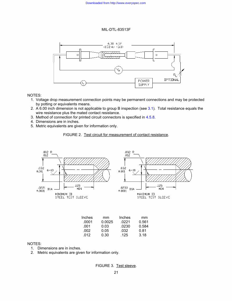
4.5.8 Contact resistance. Twenty percent, but no less than seven contacts of the mated connectors shall be tested. The potential drop of each mated pair of pins and sockets shall be measured after temperature stabilization with the specified current flowing through the contacts at an ambient temperature of 25!C #3!C (see 3.5.6). The applicable test circuit shall be as shown on figure 2, and contacts shall be fully mated (see figure 1). For printed circuit connectors the voltage leads shall be located at the extreme ends of the contacts. For crimp or solder type contacts that are mated to PC connectors the voltage leads shall be located on the wire, at closest point to contact without touching contact.
Downloaded from http://www.everyspec.com
MIL-DTL-83513F
20
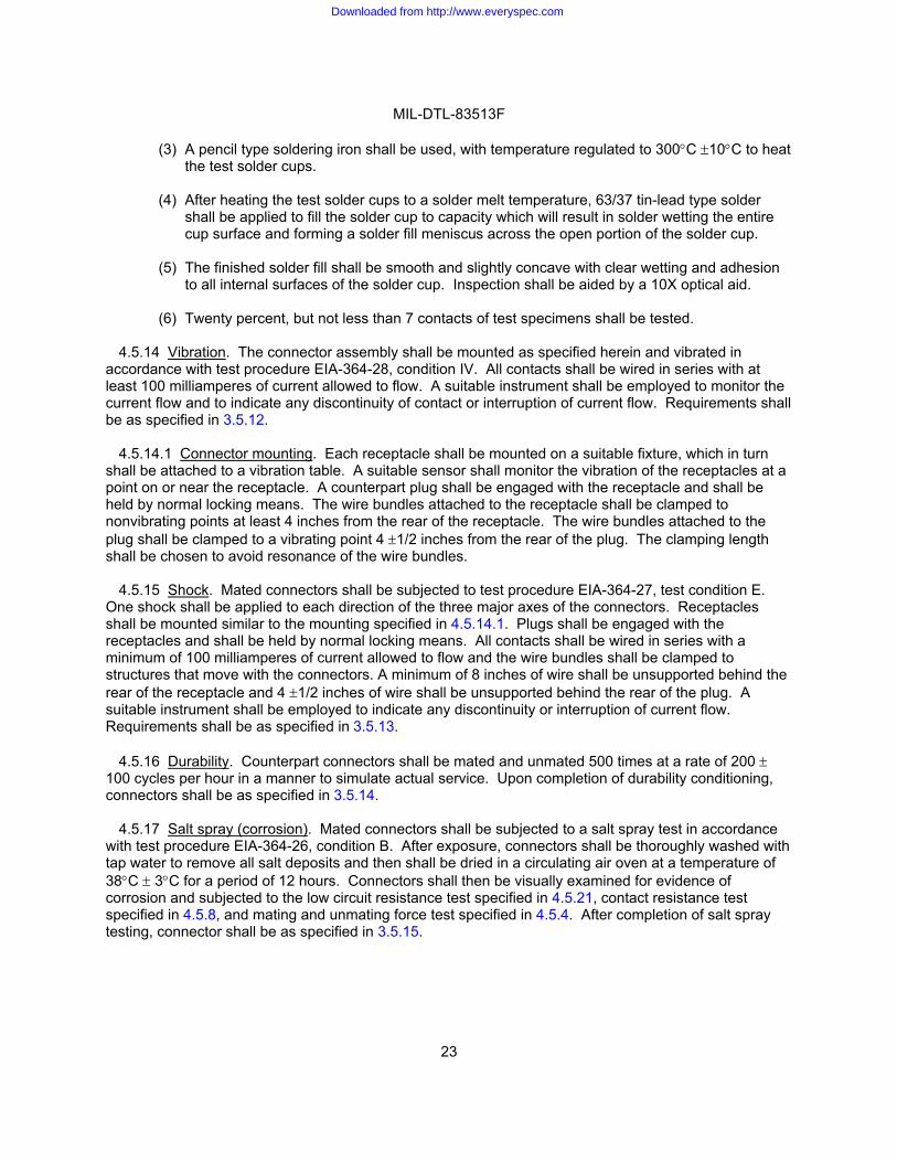
4.5.9 Contact engagement and separation forces. Twenty percent, but no less than seven contacts in each connector shall be tested. Socket test sleeve (see figure 3) shall be mounted in a suitable position or fixture for applying gradually increasing axial loads for the engagement and separation of pin contacts from the test bushing. The pin contact shall not bottom in the socket test sleeve. Engagement and separation forces shall meet the requirements as specified in 3.5.7 when contacts are tested as follows:
a. Insert and separate a pin contact in a minimum diameter test sleeve, then insert and remove the
pin contact in a maximum diameter test sleeve. During separation from the maximum test sleeve, the minimum separation force shall be as specified in 3.5.7.
b. Insert and separate a pin contact in a minimum diameter test sleeve three times. During the third
cycle, the engagement force shall be as specified in 3.5.7.
FIGURE 1. Connectors, fully mated.
Downloaded from http://www.everyspec.com
MIL-DTL-83513F
21
NOTES:
1. Voltage drop measurement connection points may be permanent connections and may be protected by potting or equivalents means.
2. A 6.00 inch dimension is not applicable to group B inspection (see 3.1). Total resistance equals the wire resistance plus the mated contact resistance.
3. Method of connection for printed circuit connectors is specified in 4.5.8. 4. Dimensions are in inches. 5. Metric equivalents are given for information only.
FIGURE 2. Test circuit for measurement of contact resistance.
Inches mm Inches mm .0001 0.0025 .0221 0.561 .001 0.03 .0230 0.584 .002 0.05 .032 0.81 .012 0.30 .125 3.18
NOTES:
1. Dimensions are in inches. 2. Metric equivalents are given for information only.
FIGURE 3. Test sleeve.
Downloaded from http://www.everyspec.com

MIL-DTL-83513F
22
4.5.10 Temperature cycling. Unmated connectors shall be tested in accordance with test procedure EIA-364-32, condition I, 5 cycles, except that the maximum temperature shall be 125!C +3!C, -0!C. At the completion of the last cycle, the connectors shall be returned to room temperature for further examination and shall meet the requirements specified in 3.5.8.
4.5.11 Humidity. The connectors shall be fully wired and mated. Then the connectors shall be subjected to testing in accordance with test procedure EIA-364-31, method IV (except steps 7a and 7b shall not be required). The following exceptions and details specified in 3.5.9 shall apply:
a. After the 24-hour conditioning period, the insulation resistance shall be measured as specified in 3.5.5.
b. Upon completion of step 6 of the final cycle, connectors shall be removed from the chamber,
unmated, and surface moisture removed from the inserts. Dielectric withstanding voltage test specified in 4.5.6.1 (sea level) and insulation resistance test specified in 4.5.7 shall be performed for all classes of connectors within 1 to 2 hours.
4.5.12 Resistance to soldering heat (see 3.5.10). All solder cup termination type connectors shall be
tested as follows:
a. Unless otherwise specified, the applicable copper wire size 2 to 4 inches in length, properly prepared for the applicable solder cup size shall be inserted into the contact termination. Seven contacts or 20 percent of the contacts, whichever is greater, shall be tested.
b. The test specimens shall be fluxed (see 3.5.20) accordingly with liquid or other techniques.
c. Unless otherwise specified, a pencil type solder iron rated for 25 watts shall be used.
d. The solder iron shall be heated to a temperature of 360!C #10!C and shall be applied along with
SN-63 solder to the termination for a time duration allowing the solder to become liquid and remain in the liquid state for 4 to 5 seconds.
e. After application, the soldering iron shall be removed and a visual and mechanical inspection
performed. The visual inspection shall be at 10X.
f. The connector shall show no evidence of distortion or damage to any area of the connector housing or evidence of contact misalignment.
4.5.13 Solderability (see 3.5.11).
a. Connectors with wire terminations (A-A-59551) shall be tested for solderability in accordance with
MIL-STD-202, method 208.
b. Connectors with wire cup termination shall be tested for solderability using the following methods.
(1) Test samples shall not be cleaned prior to soldering.
(2) Test sample connectors shall have the solder cups dipped in, or brushed with, flux type RMA just prior to the application of solder.
Downloaded from http://www.everyspec.com
MIL-DTL-83513F
23
(3) A pencil type soldering iron shall be used, with temperature regulated to 300!C #10!C to heat the test solder cups.
(4) After heating the test solder cups to a solder melt temperature, 63/37 tin-lead type solder
shall be applied to fill the solder cup to capacity which will result in solder wetting the entire cup surface and forming a solder fill meniscus across the open portion of the solder cup.
(5) The finished solder fill shall be smooth and slightly concave with clear wetting and adhesion
to all internal surfaces of the solder cup. Inspection shall be aided by a 10X optical aid.
(6) Twenty percent, but not less than 7 contacts of test specimens shall be tested.
4.5.14 Vibration. The connector assembly shall be mounted as specified herein and vibrated in accordance with test procedure EIA-364-28, condition IV. All contacts shall be wired in series with at least 100 milliamperes of current allowed to flow. A suitable instrument shall be employed to monitor the current flow and to indicate any discontinuity of contact or interruption of current flow. Requirements shall be as specified in 3.5.12.
4.5.14.1 Connector mounting. Each receptacle shall be mounted on a suitable fixture, which in turn shall be attached to a vibration table. A suitable sensor shall monitor the vibration of the receptacles at a point on or near the receptacle. A counterpart plug shall be engaged with the receptacle and shall be held by normal locking means. The wire bundles attached to the receptacle shall be clamped to nonvibrating points at least 4 inches from the rear of the receptacle. The wire bundles attached to the plug shall be clamped to a vibrating point 4 #1/2 inches from the rear of the plug. The clamping length shall be chosen to avoid resonance of the wire bundles.
4.5.15 Shock. Mated connectors shall be subjected to test procedure EIA-364-27, test condition E. One shock shall be applied to each direction of the three major axes of the connectors. Receptacles shall be mounted similar to the mounting specified in 4.5.14.1. Plugs shall be engaged with the receptacles and shall be held by normal locking means. All contacts shall be wired in series with a minimum of 100 milliamperes of current allowed to flow and the wire bundles shall be clamped to structures that move with the connectors. A minimum of 8 inches of wire shall be unsupported behind the rear of the receptacle and 4 #1/2 inches of wire shall be unsupported behind the rear of the plug. A suitable instrument shall be employed to indicate any discontinuity or interruption of current flow. Requirements shall be as specified in 3.5.13.
4.5.16 Durability. Counterpart connectors shall be mated and unmated 500 times at a rate of 200 # 100 cycles per hour in a manner to simulate actual service. Upon completion of durability conditioning, connectors shall be as specified in 3.5.14.
4.5.17 Salt spray (corrosion). Mated connectors shall be subjected to a salt spray test in accordance with test procedure EIA-364-26, condition B. After exposure, connectors shall be thoroughly washed with tap water to remove all salt deposits and then shall be dried in a circulating air oven at a temperature of 38!C # 3!C for a period of 12 hours. Connectors shall then be visually examined for evidence of corrosion and subjected to the low circuit resistance test specified in 4.5.21, contact resistance test specified in 4.5.8, and mating and unmating force test specified in 4.5.4. After completion of salt spray testing, connector shall be as specified in 3.5.15.
Downloaded from http://www.everyspec.com
MIL-DTL-83513F
24
4.5.18 Fluid immersion. Unmated connectors shall be immersed fully in the fluids specified below for the required periods. At least one connector shall be immersed in each fluid. After removal from the fluid, each connector shall remain for 1 hour in free air at room conditions. Subsequent testing shall be performed on connectors mated with the same mating connectors used previously in the test. The connector shall be mated as specified in 4.5.4. The mating force shall not exceed the force requirement specified in 3.5.2 at the distances denoted on figure 3. Following mating, connectors shall be cleaned in a suitable solvent to remove the cleaning solvents and lubricating oil.
a. Lubricating oil Aircraft turbine engines, synthetic base: 20 hours.
b. Coolant-dielectric fluid synthetic silicate ester base lubricant (coolanol 25 or equivalent): 1 hour # 1 minute.
4.5.19 Insert retention (class M connectors only). Inserts shall be subjected to axial loads in each
direction. Loading shall be accomplished by applying air pressure or equivalent load. The pressure shall be increased gradually at a rate approximately 10 psi per second until the pressure specified in 3.5.17 is reached. The insert shall retain its normal position in the connector shell for at least 5 seconds at the maximum pressure specified in 3.5.17.
4.5.20 Crimp tensile strength (type I contacts only). Specimens of contacts crimped to wires shall be placed in a standard tensile-testing machine and an axial load shall be applied. The holding surfaces or clamps of tensile testing machine may be serrated to provide sufficient gripping or holding strength. The rate of travel of the head of the testing machine shall be approximately 1 inch per minute minimum. The crimp tensile shall be as specified in 3.5.18.
4.5.21 Low-signal level contact resistance (see 3.5.19). The low-signal level contact resistance test shall be in accordance with test procedure EIA-364-23. The following detail shall apply: Environmental conditioning not required.
4.5.22 Thermal vacuum outgassing (space classes only, see 3.5.20). All nonmetallic materials, including lubricants, used in the manufacture of these connectors shall be tested in accordance with SP-R-0022 or ASTM E595 to determine the maximum TML of the original specimen mass and the VCM content of the original specimen mass. For the purpose of determining TML and VCM of connectors, the original specimen mass shall be the assembled connector mass excluding metallic parts. The TMC and VCM for the connectors may be determined by testing the specific materials of the connector and calculating the loss for the connector.
4.5.23 Marking performance. The marking shall meet the requirements specified in 3.6 when tested in
accordance with MIL-STD-202, method 215.
5. PACKAGING 5.1 Packaging. For acquisition purposes, the packaging requirement shall be as specified in the contract or order (see 6.2). When packaging of materiel is to be performed by DoD or in-house contractor personnel, these personnel need to contact the responsible packaging activity to ascertain requisite packaging requirements. Packaging requirements are maintained by the Inventory Control Point's packaging activity within the Military Service or Defense Agency, or within the military service's system commands. Packaging data retrieval is available from the managing Military Department or Defense Agency's automated packaging files, CD-ROM products, or by contacting the responsible packaging activity.
Downloaded from http://www.everyspec.com
MIL-DTL-83513F
25
6. NOTES
(This section contains information of a general or explanatory nature, that may be helpful but is not mandatory.)
6.1 Intended use. These connectors are intended for use in airborne, ground support, and shipboard electrical and electronic equipment in nonenvironmental resisting applications where the operating temperature ranges from -55!C to +125!C. These connectors are not intended for use in blind mating rack and panel applications.
6.1.1 Class M connectors. Class M connectors may be used in applications where some exposure to high humidity is experienced.
6.1.2 Class P connectors. Class P connectors are intended for use in low humidity controlled environments such as telecommunications, computers, sealed enclosures, etc.
6.1.3 Space application. Electroless nickel is intended to be used in space applications. Cadmium is not to be used in space applications.
6.2 Acquisition requirements. Acquisition documents should specify the following:
a. Title, number, and date of this specification.
b. Title, number, and date of the applicable specification sheet and the complete PIN (see 3.1).
6.3 Qualification. With respect to products requiring qualification, awards will be made only for products which are at the time of award of contract, qualified for inclusion in Qualified Products List QPL No. 83513 whether or not such products have actually been so listed by that date. The attention of the contractors is called to these requirements, and manufacturers are urged to arrange to have the products that they propose to offer to the Federal Government tested for qualification in order that they may be eligible to be awarded contracts or purchase orders for the products covered by this specification. Information pertaining to qualification of products may be obtained from the Defense Supply Center Columbus (DSCC-VQ), Document Control Unit, Columbus, OH 43218-3990 or e mail [email protected] .
6.4 Tin whisker growth. The use of alloys with tin content greater than 97 percent may exhibit tin
whisker growth problems after manufacture. Tin whiskers may occur anytime from a day to years after, and can develop under typical operation conditions on products that use such materials. Conformal coatings applied over top of a whisker-prone surface will not prevent the formation of tin whiskers. Alloys of 3 percent lead have shown to inhibit the growth of tin whiskers.
6.5 Subject term (key word) listing.
Arrangement Contacts Dielectric Engagement Force Hardware Inserts Insulation resistance Materials Metals
Downloaded from http://www.everyspec.com
MIL-DTL-83513F
26
Military specification Packaging Plug Receptacle
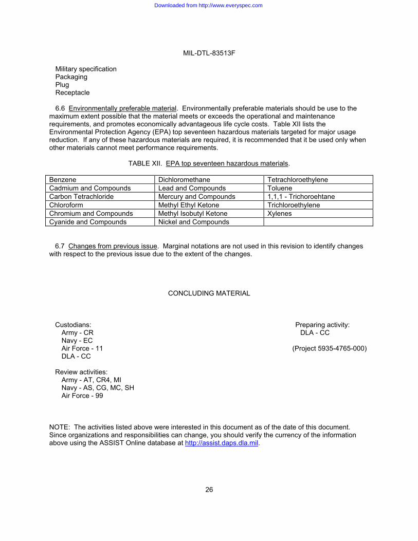
6.6 Environmentally preferable material. Environmentally preferable materials should be use to the
maximum extent possible that the material meets or exceeds the operational and maintenance requirements, and promotes economically advantageous life cycle costs. Table XII lists the Environmental Protection Agency (EPA) top seventeen hazardous materials targeted for major usage reduction. If any of these hazardous materials are required, it is recommended that it be used only when other materials cannot meet performance requirements.
TABLE XII. EPA top seventeen hazardous materials. Benzene Dichloromethane Tetrachloroethylene Cadmium and Compounds Lead and Compounds Toluene Carbon Tetrachloride Mercury and Compounds 1,1,1 - Trichoroehtane Chloroform Methyl Ethyl Ketone Trichloroethylene Chromium and Compounds Methyl Isobutyl Ketone Xylenes Cyanide and Compounds Nickel and Compounds 6.7 Changes from previous issue. Marginal notations are not used in this revision to identify changes with respect to the previous issue due to the extent of the changes.
CONCLUDING MATERIAL
Custodians: Preparing activity: Army - CR DLA - CC Navy - EC Air Force - 11 (Project 5935-4765-000) DLA - CC
Review activities:
Army - AT, CR4, MI Navy - AS, CG, MC, SH Air Force - 99
NOTE: The activities listed above were interested in this document as of the date of this document. Since organizations and responsibilities can change, you should verify the currency of the information above using the ASSIST Online database at http://assist.daps.dla.mil.
Downloaded from http://www.everyspec.com