Dovetail Jig - Axminster Tools & Machinery · What’s Included 3 Quantity Item Part Model Number...
32
Code 506300 • Through Dovetail • Lapped/Half Blind Dovetail • Finger/ Box Joint AT&M: 06/04/2018 BOOK REF: 508484 Dovetail Jig
Transcript of Dovetail Jig - Axminster Tools & Machinery · What’s Included 3 Quantity Item Part Model Number...
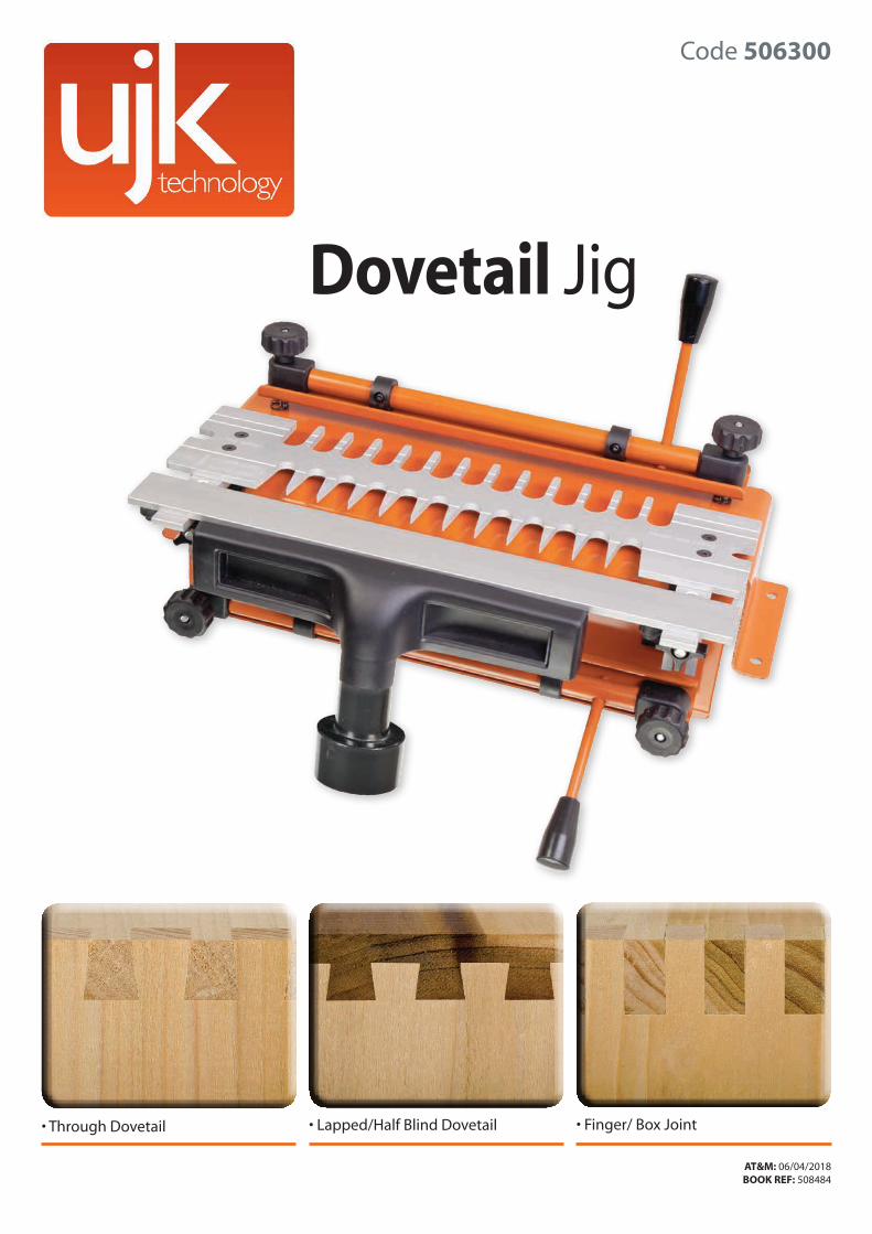
Code 506300
• Through Dovetail • Lapped/Half Blind Dovetail • Finger/ Box Joint
AT&M: 06/04/2018 BOOK REF: 508484
Dovetail Jig

Index of Contents
2
Copyright
The symbols below advise that you follow the correct safety procedures when using this product.
Fully read manualand safety instructions
before use
Eye protectionshould be worn
Ear protectionshould be worn
Dust maskshould be worn
This product has been wholly manufactured
in TAIWAN incorporation with Axminster Tools & Machinery Ltd
Index of Contents 02
Copyright 02
What’s Included 03
Introduction 04
Key Features 04
General Instructions for 230V Routers 04-05
Safety Instructions for use of Routers 05
Dovetail Jig Assembly 06-07
Illustration and Parts Description 08-09-10
Dovetail Jig Set-up 11
UJK Dovetail Jig Processes
(Chapter 0.1) Process for Through Dovetail 12-13-14-15-16-17
(Chapter 0.2) Process for Lapped/Half Blind Dovetail 17-18-19-20-21-22
(Chapter 0.3) Process for Finger/Box Joint 23-24-25
Exploded Diagram/Parts List 26-27
Notes 28-29-30-31
What’s Included
3
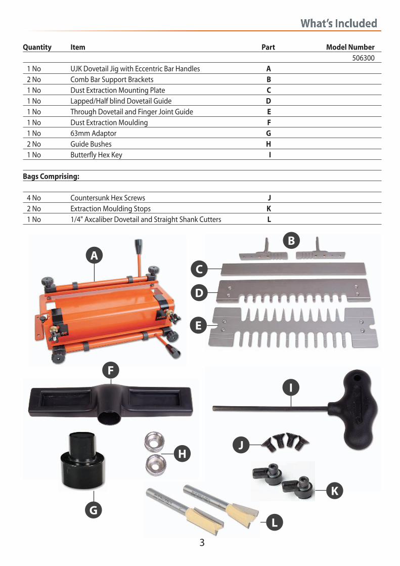
Quantity Item Part Model Number 506300 1 No UJK Dovetail Jig with Eccentric Bar Handles A 2 No Comb Bar Support Brackets B 1 No Dust Extraction Mounting Plate C 1 No Lapped/Half blind Dovetail Guide D 1 No Through Dovetail and Finger Joint Guide E 1 No Dust Extraction Moulding F 1 No 63mm Adaptor G 2 No Guide Bushes H 1 No Butterfly Hex Key I
Bags Comprising:
4 No Countersunk Hex Screws J 2 No Extraction Moulding Stops K 1 No 1/4" Axcaliber Dovetail and Straight Shank Cutters L
AB
C
D
E
F
H
I
K
L
J
G
Introduction
4
General Instructions for 230V Routers
Good Working Practices/Safety
The following suggestions will enable you to observe good working practices, keep yourself and fellowworkers safe and maintain your tools and equipment in good working order.
Always carry the machine in its carrying case. If the case is not available do not carry the machine with a cutter fitted and protruding below the base. The machines are not designed for sub-aqua operation, do not use when or where they are liable to get soaking wet. If machines are set up in the open and it starts to rain (unusual though this would be in U.K.), cover them up or move them into the dry. If machines have gotten wet, dry them off as soon as possible, with a cloth or paper towel. Do not use 230Va.c. powered machines anywhere within the site area that is flooded or puddled, and do not trail extension cables across wet areas. Keep the machines clean; it will enable you to more easily see any damage that may have occurred. Clean the machine with a damp cloth if needs be, do not use any solvents or cleaners, as these may cause damage to any plastic parts or to the electrical components. Keep the work area as uncluttered as is practical, this includes personnel as well as material. Under no circumstances should CHILDREN be allowed
• Half blind, through dovetails and finger joints
• 300 Capacity, 6-28mm thickness of material
• Heavy gauge steel pressings
• Stabiliser bar for more accurate machining
• Supplied with a pair of 1/4" shank cutters
The UJK Technology Dovetail Jig can be used to cut half blind dovetails for drawer construction, as well as precise comb or finger joints which could be used, for example, in utility furniture. It will also cut through dovetails, which would be ideally suited for a project like a toolbox. This tool is robustly made from heavy gauge, 3.5mm steel pressing and is very simple to set up and use. Fitted with cam action clamps, the workpieces are held quickly and securely while the smooth anodised finish on the 6mm thick, machined finger template ensures that both parts of the joint are cut accurately and cleanly. The jig can be used with any router that will take 1/2” or 8mm shank cutters. It also has a pre-set router depth
adjustment knob as well as a unique stabiliser bar located in front of the comb, which provides a much greater surface area on which to bear the router base. A matched pair of Axcaliber cutters (7° dovetail/straight) and an additional guide bush adaptor to suit the router should also be purchased. The UJK Dovetail Jig also incorporates a 62mm dust extraction port to aid safe and efficient operation. Supplied with 2 x 6mm thick aluminium combs, American style threaded guide bush as well as full instructions. Material capacity: 300mm width, 6–28mm thickness.
Key Features
• Finger joint 1/2" (12.7mm) width, maximum board
thickness 20mm
• American style threaded guide bush (included)
• Guide bush adaptor to suit your router (additional
parts required)
• 2 x 6mm thick aluminium guide templates
These tools are supplied with a moulded 13 Amp Plug and 3 core power cable. Before using the tool inspectthe cable and the plug to make sure that neither are damaged. If any damage is visible have the toolinspected/repaired by a suitably qualified person. Ifit is necessary to replace the plug, it is preferable to usean ‘unbreakable’ type that will resist damage on site. Only use a 13 Amp plug, make sure the terminal postsand the cable clamp are tightened securely. Fuse at 13 Amp. If extension leads are to be used, carry out thesame safety checks on them and ensure that they are correctly rated to safely supply the current that isrequired for your machine.
WARNING!! KEEP TOOLS AND EQUIPMENT OUT OF THE REACH OF YOUNG CHILDREN
Mains Powered Tools
Primary Precautions
Work Place/Environment
General Instructions for 230V Routers
5
Safety Instructions for use of Routers
in work areas. It is good practice to leave the machine unplugged until work is about to commence, also make sure to unplug the machine when it is not in use, or unattended. Always disconnect by pulling on the plug body and not the cable. Once you are ready to commence work, fit the cutter and remove all tools used in the setting operations (if any) and place safely out of the way. Clamp the workpiece to a stable work surface, check that the ‘cutting path’ is unobstructed, and observe theold woodworkers’ adage of ‘never putting your hands closer than one handbreadth to the cutting tool’. Do not attempt to mould or work any pieces that can not be held by the clamp. Make sure you are comfortable before you start work,
balanced, not reaching etc. If the work you are carrying out is liable to generate flying grit, dust or chips, wear the appropriate safety clothing, goggles, gloves, masks etc. If the work operation appears to be excessively noisy, wear ear defenders. If you wear your hair in a long style, wearing a cap, safety helmet, hairnet, even a sweatband, will minimise the possibility of your hair being caught up in the rotating parts of the tool, likewise, consideration should be given to the removal of rings and wristwatches, if these are liable to be a ‘snag’ hazard. Do not work with cutting tools of any description if you are tired, your attention is wandering or you are being subjected to distraction. A deep cut, a lost fingertip or worse, is not worth it!
1. Make sure you have read and fully understood theGeneral Instructions and safety precautions that applyto your router. 2. Before connecting the machine to the supply; checkfor obvious signs of damage, paying particular attentionto the plug and the power cable. Rectify or have rectified any damage you discover. Fit and set the guide bush, using the Guide Bush Check Centre, to checkconcentricity, if you are doubtful of correct centering.Check the cutter bit you are about to fit is the correcttool for the job. In this case a 8mm or ½” Router Bit. Check the bit for damage, make sure it is sharp andclean, check you have the correct collet for the cutter shank size you are about to fit, ensure that a sufficient length of the shank is inserted in the collet to guarantee a secure fixing. (‘K’ line on cutter shank)Conversely, ensure there is sufficient length of cutter to carry out the cutting task. Make sure that the tools you use to fit the cutter bit, or any accessories are the correctones, DO NOT risk damaging the router by using thewrong size spanners, Hex keys, etc. Make sure the ‘chipscreens’ (if available) are fitted securely. If dustextraction is available, connect it. 3. Check that all accessories, tools etc., that have beenused to set the machine up, are removed and setcarefully aside or stowed away correctly.
4. Set the depth of cut, either as one plunge orincrementally (Staight cutters only). 5. Ensure the machine is switched off. Never engage atrigger hold-on unless you are actually holding themachine. Plug the power cable into a correctly ratedswitched socket outlet. If extension leads are beingused, check these for damage, do not use if damaged,check that any extension cables in use are correctlyrated for use with your machine. Switch on the supply. 6. Make sure you are holding the machine in a safeposition, ensure that the cutter bit is not in contactwith anything, and the ‘plunge’ is locked off. Give themachine a quick “burst”, to ensure that everything is working correctly, check especially for vibration, which might indicate that the cutter is incorrectly fitted. If you disconnect the machine; re-fit the cutter and test again. 7. If there is any vibration make sure that the jig is clamped or fixed firmly to the workbench. 8. Make sure that the power cable is safely positioned away from the operating area, and when operatingthe router, the movement of this operation will notdrag it to within range of the router or cutter.
Dovetail Jig Asssembly
6
Fig 01-02
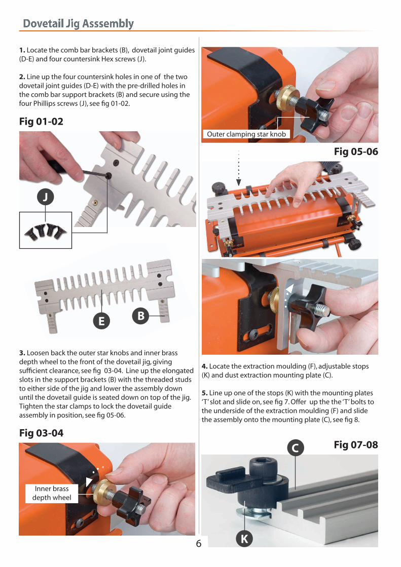
1. Locate the comb bar brackets (B), dovetail joint guides (D-E) and four countersink Hex screws (J). 2. Line up the four countersink holes in one of the twodovetail joint guides (D-E) with the pre-drilled holes in the comb bar support brackets (B) and secure using the four Phillips screws (J), see fig 01-02.
3. Loosen back the outer star knobs and inner brass depth wheel to the front of the dovetail jig, giving sufficient clearance, see fig 03-04. Line up the elongated slots in the support brackets (B) with the threaded studs to either side of the jig and lower the assembly down until the dovetail guide is seated down on top of the jig. Tighten the star clamps to lock the dovetail guide assembly in position, see fig 05-06.
Fig 03-04
Fig 05-06
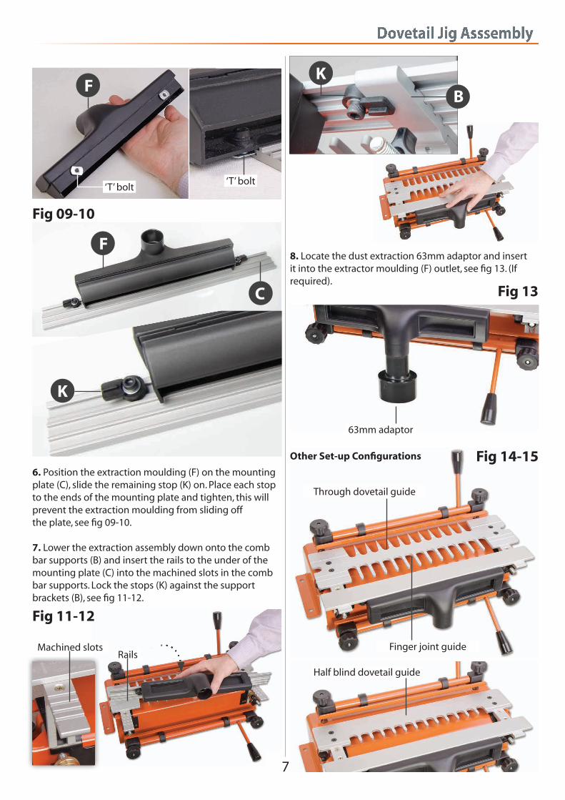
4. Locate the extraction moulding (F), adjustable stops (K) and dust extraction mounting plate (C). 5. Line up one of the stops (K) with the mounting plates ‘T’ slot and slide on, see fig 7. Offer up the the ‘T’ bolts to the underside of the extraction moulding (F) and slide the assembly onto the mounting plate (C), see fig 8.
Fig 07-08C
K
Inner brassdepth wheel
Outer clamping star knob
E B
J
Dovetail Jig Asssembly
7
6. Position the extraction moulding (F) on the mounting plate (C), slide the remaining stop (K) on. Place each stop to the ends of the mounting plate and tighten, this will prevent the extraction moulding from sliding off the plate, see fig 09-10. 7. Lower the extraction assembly down onto the comb bar supports (B) and insert the rails to the under of the mounting plate (C) into the machined slots in the comb bar supports. Lock the stops (K) against the support brackets (B), see fig 11-12.
Fig 09-10
Fig 11-12
8. Locate the dust extraction 63mm adaptor and insert it into the extractor moulding (F) outlet, see fig 13. (If required).
Fig 14-15
Fig 13
Finger joint guide
Half blind dovetail guide
Through dovetail guide
63mm adaptor
Machined slotsRails
F
C
F
K
‘T’ bolt‘T’ bolt
Other Set-up Configurations
KB
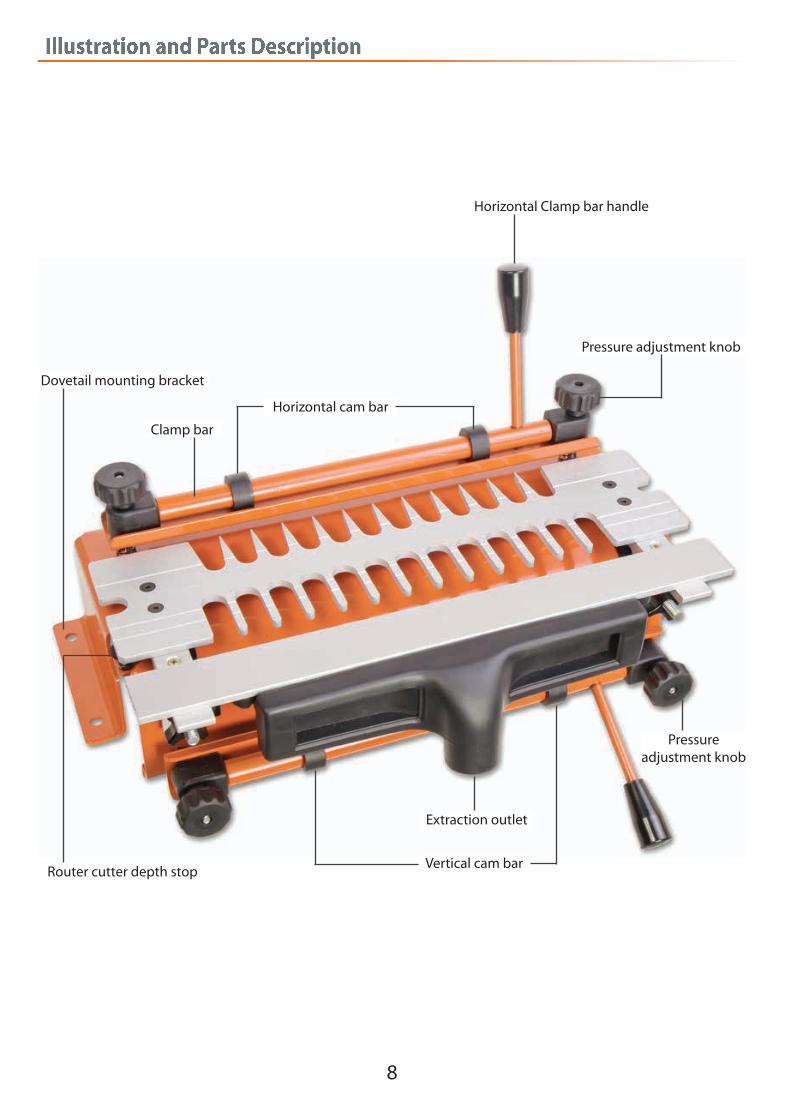
Illustration and Parts Description
8
Horizontal Clamp bar handle
Horizontal cam bar
Clamp bar
Dovetail mounting bracket
Pressure adjustment knob
Router cutter depth stopVertical cam bar
Extraction outlet
Pressureadjustment knob
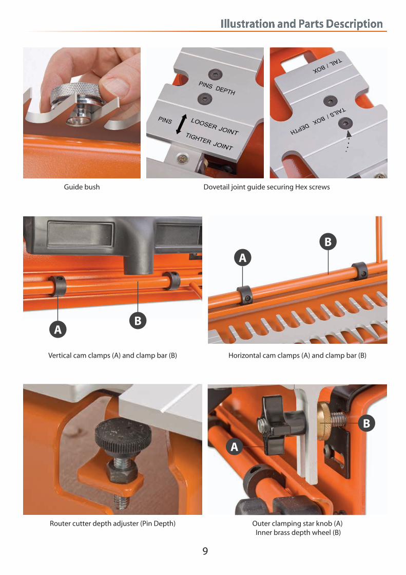
Illustration and Parts Description
9
Vertical cam clamps (A) and clamp bar (B) Horizontal cam clamps (A) and clamp bar (B)
Router cutter depth adjuster (Pin Depth) Outer clamping star knob (A) Inner brass depth wheel (B)
Guide bush Dovetail joint guide securing Hex screws
A
A
B
B
A
B

Illustration and Parts Description
10
Mounting bracket holes Vertical pressure adjustment knob Side stop cap screw (A) Side stop (B)
Horizontal clamping bar assembly Clamping bar plate
Support plate for extraction outlet
Dovetail jig rear view
Dovetail joint guide
B
A
Dovetail Jig Set-up
11
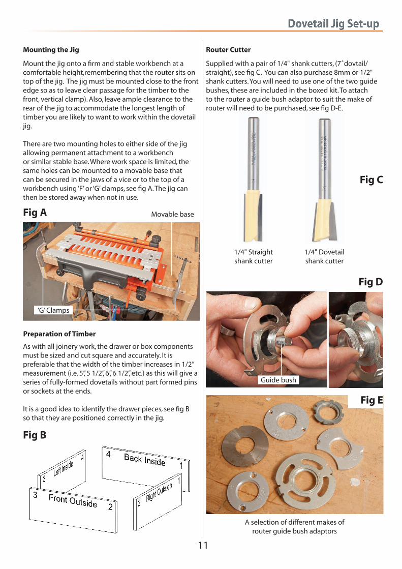
Mounting the Jig
Mount the jig onto a firm and stable workbench at a comfortable height,remembering that the router sits on top of the jig. The jig must be mounted close to the front edge so as to leave clear passage for the timber to the front, vertical clamp). Also, leave ample clearance to the rear of the jig to accommodate the longest length of timber you are likely to want to work within the dovetail jig. There are two mounting holes to either side of the jig allowing permanent attachment to a workbenchor similar stable base. Where work space is limited, the same holes can be mounted to a movable base thatcan be secured in the jaws of a vice or to the top of a workbench using ‘F’ or ‘G’ clamps, see fig A. The jig can then be stored away when not in use.
Fig A
Preparation of Timber
As with all joinery work, the drawer or box components must be sized and cut square and accurately. It is preferable that the width of the timber increases in 1/2” measurement (i.e. 5”, 5 1/2”, 6”, 6 1/2”, etc.) as this will give a series of fully-formed dovetails without part formed pins or sockets at the ends. It is a good idea to identify the drawer pieces, see fig B so that they are positioned correctly in the jig.
Fig B
Router Cutter
Supplied with a pair of 1/4" shank cutters, (7˚dovtail/straight), see fig C. You can also purchase 8mm or 1/2" shank cutters. You will need to use one of the two guide bushes, these are included in the boxed kit. To attach to the router a guide bush adaptor to suit the make of router will need to be purchased, see fig D-E.
Fig C
Fig D
Fig E
A selection of different makes of router guide bush adaptors
1/4" Straightshank cutter
1/4" Dovetailshank cutter
Guide bush
‘G’ Clamps
Movable base

UJK Dovetail Jig Processes
12
(Chapter 0.1)
Process for Through Dovetail
1. Select the through dovetail and finger joint comb, (E). Bolt this onto the comb bar support brackets (B) using the four countersunk hex screws (J) making sure that engraved wording of ‘Tail /Box’ is facing the front of the jig, see fig 01 (see parts list on page 3).
0.1 Fig 01
Dovetail joint guide
Marking guage
0.1 Fig 02
Hex screw
2. Whilst the comb bar assembly is removed from the jig, on the left hand side of the jig, slacken the Hex screwthat hold the side stop location bracket. Slide the bracket as far left as possible and gently re-tighten hex screw, see fig 02.
0.1 Fig 03-04
3. To help set up the cutter depth it is worth using acutting gauge. Scribe a depth line across the end of the boards, use the boards to set the cutting gauge up, take one jointing corner, set the gauge to the thicknessof one board, see fig 03. Once the gauge is set, mark this depth across the end of the other jointing board, see fig 04. It is also worth labelling the boards, the ‘Pin’ boards being the front and back of a drawer and the ‘Tail’ boards being the sides.
4. Locate the Comb bar assembly onto the jig, check the legs of the comb bar support brackets are fitted between the black star knob (A) and the brass depth adjustment wheel (B), and that the correct template comb is facing forward toward the front of the jig, see fig 05. 5. Position the boards within the jig, the ‘Tail’ board (drawer sides) being cut first. These need to be loaded into the vertical position, with scribe line facing towards the user. Load a board of the same thickness as the ‘Pin’ boards (can use the pin board) placed in the horizontal position in the jig, see fig 06.
Scribe line
0.1 Fig 05
AB
0.1 Fig 06
Pin
Pin
Tail
Tail
Tail
UJK Dovetail Jig Processes
13
0.1 Fig 10
Continues Over....
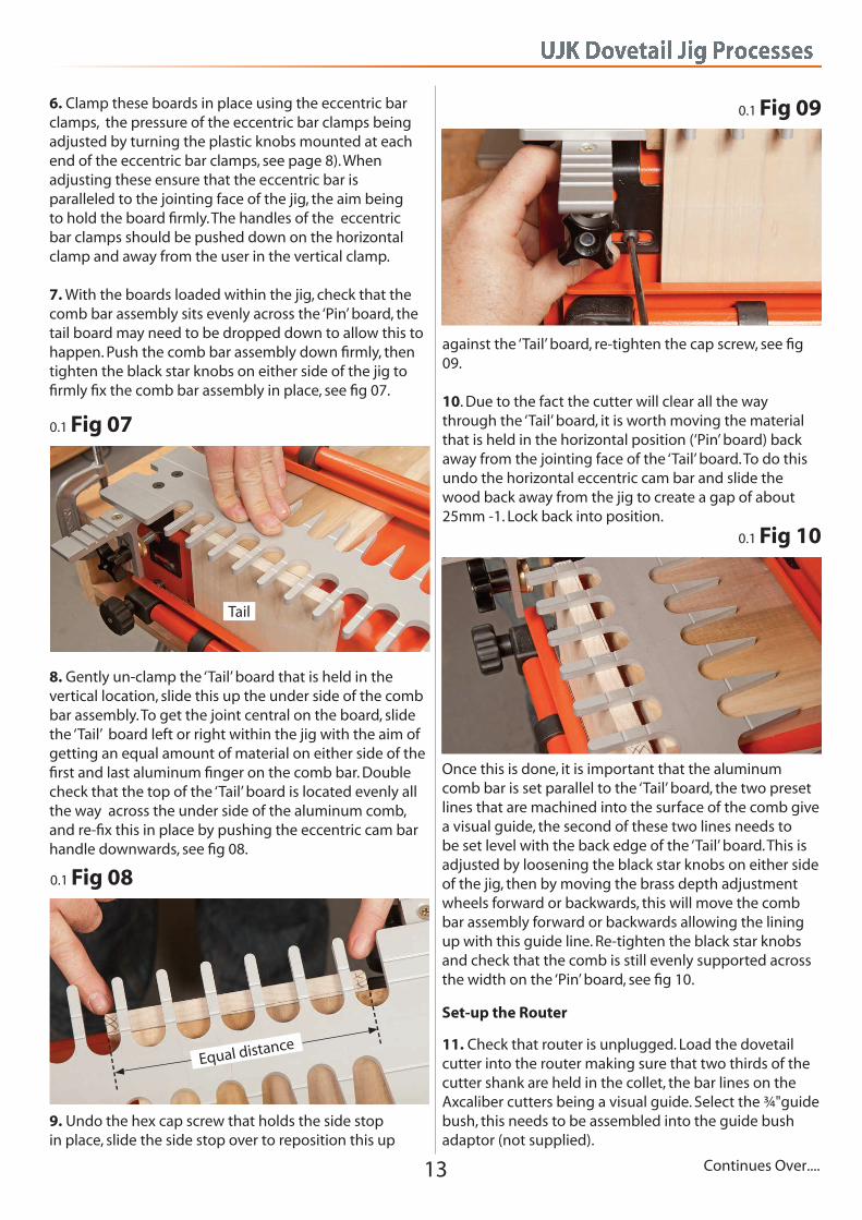
6. Clamp these boards in place using the eccentric bar clamps, the pressure of the eccentric bar clamps being adjusted by turning the plastic knobs mounted at each end of the eccentric bar clamps, see page 8). When adjusting these ensure that the eccentric bar is paralleled to the jointing face of the jig, the aim being to hold the board firmly. The handles of the eccentric bar clamps should be pushed down on the horizontal clamp and away from the user in the vertical clamp. 7. With the boards loaded within the jig, check that the comb bar assembly sits evenly across the ‘Pin’ board, the tail board may need to be dropped down to allow this to happen. Push the comb bar assembly down firmly, then tighten the black star knobs on either side of the jig to firmly fix the comb bar assembly in place, see fig 07.
0.1 Fig 07
Tail
8. Gently un-clamp the ‘Tail’ board that is held in the vertical location, slide this up the under side of the comb bar assembly. To get the joint central on the board, slide the ‘Tail’ board left or right within the jig with the aim of getting an equal amount of material on either side of the first and last aluminum finger on the comb bar. Double check that the top of the ‘Tail’ board is located evenly all the way across the under side of the aluminum comb, and re-fix this in place by pushing the eccentric cam bar handle downwards, see fig 08.
0.1 Fig 08
Equal distance
0.1 Fig 09
9. Undo the hex cap screw that holds the side stop in place, slide the side stop over to reposition this up
against the ‘Tail’ board, re-tighten the cap screw, see fig 09. 10. Due to the fact the cutter will clear all the way through the ‘Tail’ board, it is worth moving the material that is held in the horizontal position (‘Pin’ board) back away from the jointing face of the ‘Tail’ board. To do this undo the horizontal eccentric cam bar and slide the wood back away from the jig to create a gap of about 25mm -1. Lock back into position.
Once this is done, it is important that the aluminum comb bar is set parallel to the ‘Tail’ board, the two preset lines that are machined into the surface of the comb give a visual guide, the second of these two lines needs to be set level with the back edge of the ‘Tail’ board. This is adjusted by loosening the black star knobs on either side of the jig, then by moving the brass depth adjustment wheels forward or backwards, this will move the comb bar assembly forward or backwards allowing the lining up with this guide line. Re-tighten the black star knobs and check that the comb is still evenly supported across the width on the ‘Pin’ board, see fig 10.
Set-up the Router
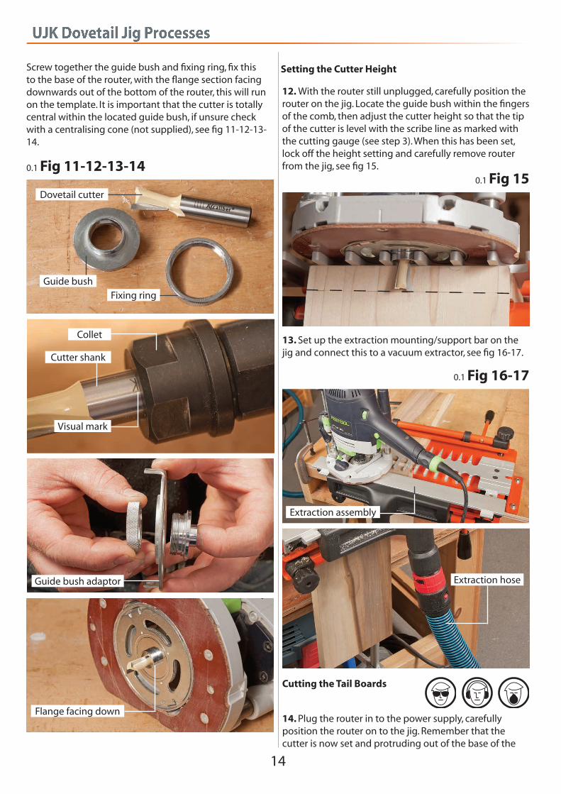
11. Check that router is unplugged. Load the dovetail cutter into the router making sure that two thirds of the cutter shank are held in the collet, the bar lines on theAxcaliber cutters being a visual guide. Select the ¾"guide bush, this needs to be assembled into the guide bush adaptor (not supplied).
UJK Dovetail Jig Processes
14
Screw together the guide bush and fixing ring, fix this to the base of the router, with the flange section facing downwards out of the bottom of the router, this will run on the template. It is important that the cutter is totally central within the located guide bush, if unsure check with a centralising cone (not supplied), see fig 11-12-13-14.
0.1 Fig 11-12-13-14
Dovetail cutter
Guide bushFixing ring
Guide bush adaptor
Cutter shank
Collet
Visual mark
Flange facing down
Setting the Cutter Height
12. With the router still unplugged, carefully position the router on the jig. Locate the guide bush within the fingers of the comb, then adjust the cutter height so that the tip of the cutter is level with the scribe line as marked with the cutting gauge (see step 3). When this has been set, lock off the height setting and carefully remove router from the jig, see fig 15.
0.1 Fig 15
13. Set up the extraction mounting/support bar on the jig and connect this to a vacuum extractor, see fig 16-17.
0.1 Fig 16-17
Extraction assembly
Extraction hose
14. Plug the router in to the power supply, carefully position the router on to the jig. Remember that the cutter is now set and protruding out of the base of the
Cutting the Tail Boards
UJK Dovetail Jig Processes
15
0.1 Fig 18
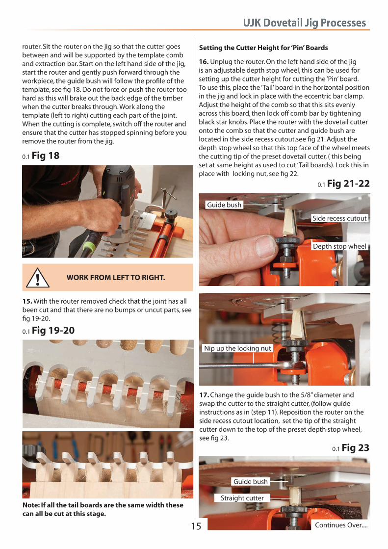
router. Sit the router on the jig so that the cutter goes between and will be supported by the template comb and extraction bar. Start on the left hand side of the jig, start the router and gently push forward through the workpiece, the guide bush will follow the profile of the template, see fig 18. Do not force or push the router too hard as this will brake out the back edge of the timber when the cutter breaks through. Work along the template (left to right) cutting each part of the joint. When the cutting is complete, switch off the router and ensure that the cutter has stopped spinning before you remove the router from the jig.
15. With the router removed check that the joint has all been cut and that there are no bumps or uncut parts, see fig 19-20.
0.1 Fig 19-20
WORK FROM LEFT TO RIGHT.
Setting the Cutter Height for ‘Pin’ Boards
16. Unplug the router. On the left hand side of the jig is an adjustable depth stop wheel, this can be used for setting up the cutter height for cutting the ‘Pin’ board. To use this, place the ‘Tail’ board in the horizontal position in the jig and lock in place with the eccentric bar clamp. Adjust the height of the comb so that this sits evenly across this board, then lock off comb bar by tightening black star knobs. Place the router with the dovetail cutter onto the comb so that the cutter and guide bush are located in the side recess cutout,see fig 21. Adjust the depth stop wheel so that this top face of the wheel meets the cutting tip of the preset dovetail cutter, ( this being set at same height as used to cut ‘Tail boards). Lock this in place with locking nut, see fig 22.
0.1 Fig 21-22
Side recess cutout
Guide bush
Nip up the locking nut
Depth stop wheel
17. Change the guide bush to the 5/8” diameter and swap the cutter to the straight cutter, (follow guide instructions as in (step 11). Reposition the router on the side recess cutout location, set the tip of the straight cutter down to the top of the preset depth stop wheel, see fig 23.
Note: If all the tail boards are the same width these can all be cut at this stage.
0.1 Fig 23
Guide bush
Straight cutter
Continues Over....
UJK Dovetail Jig Processes
16
Setting up jig for the ‘Pin’ boards
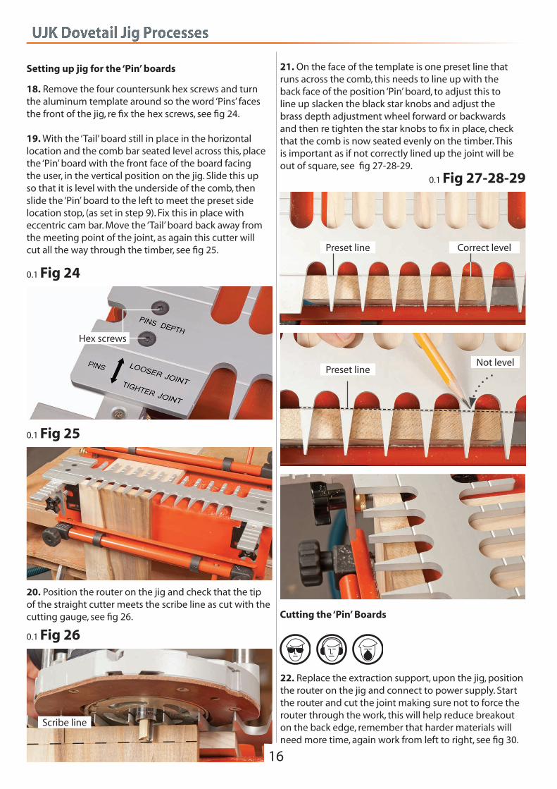
18. Remove the four countersunk hex screws and turn the aluminum template around so the word ‘Pins’ faces the front of the jig, re fix the hex screws, see fig 24. 19. With the ‘Tail’ board still in place in the horizontal location and the comb bar seated level across this, place the ‘Pin’ board with the front face of the board facingthe user, in the vertical position on the jig. Slide this upso that it is level with the underside of the comb, then slide the ‘Pin’ board to the left to meet the preset side location stop, (as set in step 9). Fix this in place with eccentric cam bar. Move the ‘Tail’ board back away from the meeting point of the joint, as again this cutter will cut all the way through the timber, see fig 25.
0.1 Fig 24
Hex screws
0.1 Fig 25
20. Position the router on the jig and check that the tip of the straight cutter meets the scribe line as cut with the cutting gauge, see fig 26.
0.1 Fig 26
Scribe line
21. On the face of the template is one preset line that runs across the comb, this needs to line up with theback face of the position ‘Pin’ board, to adjust this toline up slacken the black star knobs and adjust thebrass depth adjustment wheel forward or backwardsand then re tighten the star knobs to fix in place, check that the comb is now seated evenly on the timber. Thisis important as if not correctly lined up the joint will beout of square, see fig 27-28-29.
0.1 Fig 27-28-29
Correct levelPreset line
Preset lineNot level
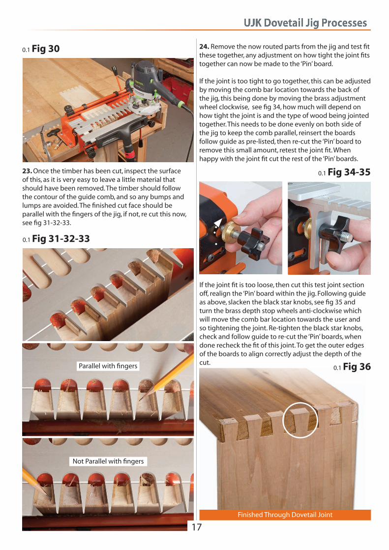
22. Replace the extraction support, upon the jig, position the router on the jig and connect to power supply. Start the router and cut the joint making sure not to force the router through the work, this will help reduce breakout on the back edge, remember that harder materials will need more time, again work from left to right, see fig 30.
Cutting the ‘Pin’ Boards
UJK Dovetail Jig Processes
17
0.1 Fig 30
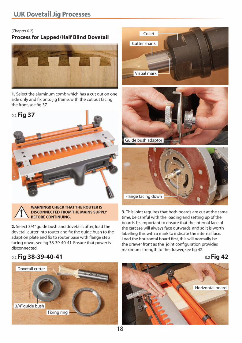
23. Once the timber has been cut, inspect the surfaceof this, as it is very easy to leave a little material that should have been removed. The timber should followthe contour of the guide comb, and so any bumps and lumps are avoided. The finished cut face should be parallel with the fingers of the jig, if not, re cut this now, see fig 31-32-33.
0.1 Fig 31-32-33
Parallel with fingers
Not Parallel with fingers
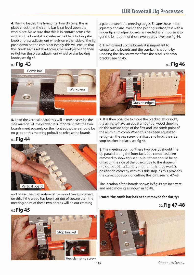
24. Remove the now routed parts from the jig and test fit these together, any adjustment on how tight the joint fits together can now be made to the ‘Pin’ board. If the joint is too tight to go together, this can be adjusted by moving the comb bar location towards the back of the jig, this being done by moving the brass adjustment wheel clockwise, see fig 34, how much will depend on how tight the joint is and the type of wood being jointed together. This needs to be done evenly on both side of the jig to keep the comb parallel, reinsert the boardsfollow guide as pre-listed, then re-cut the ‘Pin’ board to remove this small amount, retest the joint fit. When happy with the joint fit cut the rest of the ‘Pin’ boards.
0.1 Fig 34-35
If the joint fit is too loose, then cut this test joint section off, realign the ‘Pin’ board within the jig. Following guide as above, slacken the black star knobs, see fig 35 and turn the brass depth stop wheels anti-clockwise which will move the comb bar location towards the user and so tightening the joint. Re-tighten the black star knobs, check and follow guide to re-cut the ‘Pin’ boards, when done recheck the fit of this joint. To get the outer edges of the boards to align correctly adjust the depth of the cut.
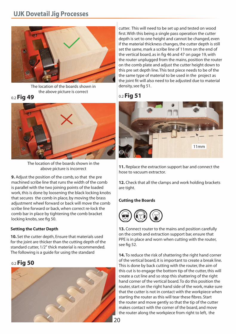
0.1 Fig 36
Finished Through Dovetail Joint
UJK Dovetail Jig Processes
18
(Chapter 0.2)
Process for Lapped/Half Blind Dovetail
1. Select the aluminum comb which has a cut out on one side only and fix onto jig frame, with the cut out facing the front, see fig 37.
0.2 Fig 37
WARNING!! CHECK THAT THE ROUTER IS DISCONNECTED FROM THE MAINS SUPPLY BEFORE CONTINUING.
0.2 Fig 38-39-40-41
2. Select 3/4” guide bush and dovetail cutter, load the dovetail cutter into router and fix the guide bush to the adaption plate and fix to router base with flange step facing down, see fig 38-39-40-41. Ensure that power is disconnected.
Guide bush adaptor
Cutter shank
Collet
Visual mark
Flange facing down
Dovetail cutter
3/4” guide bush
Fixing ring
3. This joint requires that both boards are cut at the same time, be careful with the loading and setting up of the boards. Its important to ensure that the internal face of the carcase will always face outwards, and so it is worth labelling this with a mark to indicate the internal face.Load the horizontal board first, this will normally be the drawer front as the joint configuration provides maximum strength to the drawer, see fig 42.
0.2 Fig 42
Horizontal board
UJK Dovetail Jig Processes
19
4. Having loaded the horizontal board, clamp this in place check that the comb bar is sat level upon theworkpiece. Make sure that this is in contact across the width of the board, if not, release the black locking star knob or brass adjustment wheels on either side of the jig, push down on the comb bar evenly, this will ensure that the comb bar is set level across the workpiece and then re-tighten the brass adjustment wheel or star locking knobs, see fig 43.
0.2 Fig 43Comb bar
Workpiece
5. Load the vertical board, this will in most cases be the side material of the drawer. It is important that the two boards meet squarely on the front edge, there should be no gaps at this meeting point, if so release the boards
0.2 Fig 44
and reline. The preparation of the wood can also reflect on this, if the wood has been cut out of square then the meeting point of these two boards will be out creating
Vertical board
a gap between the meeting edges. Ensure these meet squarely and are level on the jointing surface, test with a finger tip and adjust boards as needed, it is important to get the joint point of these two boards level, see fig 44. 6. Having lined up the boards it is important tocentralise the boards and the comb, this is done byundoing the Hex screw that fixes the black side stop bracket, see fig 45.
0.2 Fig 45
Hex clamping screw
Stop bracket
7. It is then possible to move the bracket left or right, the aim is to have an equal amount of wood showing on the outside edge of the first and last comb point of the aluminum comb. When this has been equalized re-tighten the cap screw that fixes and locks the sidestop bracket in place, see fig 46. 8. The meeting point of these two boards should line up parallel along the front face, (the comb has been removed to show this set up) but there should be an offset on the side of the boards due to the shape of the side stop bracket, it is important that the work is positioned correctly with this side stop as this provides the correct position for cutting the joint, see fig 47-48. The location of the boards shown in fig 49 are incorrect and need moving as shown in fig 48.
(Note: the comb bar has been removed for clarity)
0.2 Fig 46
Outside edges
0.2 Fig 47-48
Continues Over....
UJK Dovetail Jig Processes
20
The location of the boards shown inthe above picture is correct
0.2 Fig 49
The location of the boards shown in theabove picture is incorrect
9. Adjust the position of the comb, so that the pre machined scribe line that runs the width of the comb is parallel with the two joining points of the loaded work, this is done by loosening the black locking knobs that secures the comb in place, by moving the brass adjustment wheel forward or back will move the comb scribe line forward or back, when correct re-lock the comb bar in place by tightening the comb bracket locking knobs, see fig 50.
0.2 Fig 50
cutter. This will need to be set up and tested on wood first. With this being a single pass operation the cutter depth is set to one height and cannot be changed, even if the material thickness changes, the cutter depth is still set the same, mark a scribe line of 11mm on the end of the vertical board, as in fig 46 and 47 on page 19, with the router unplugged from the mains, position the router on the comb plate and adjust the cutter height down to this pre set depth line. This test piece needs to be of the the same type of material to be used in the project as the joint fit will also need to be adjusted due to material density, see fig 51.
0.2 Fig 51
11mm
11. Replace the extraction support bar and connect the hose to vacuum extractor.
12. Check that all the clamps and work holding brackets are tight.
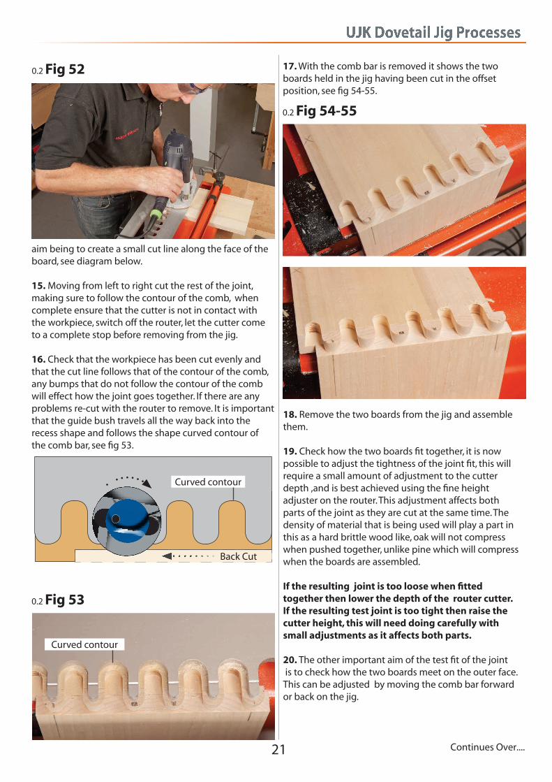
13. Connect router to the mains and position carefully on the comb and extraction support bar, ensure that PPE is in place and worn when cutting with the router, see fig 52. 14. To reduce the risk of shattering the right hand corner of the vertical board, it is important to create a break line. This is done by back cutting with the router, the aim of this cut is to engage the bottom tip of the cutter, this will create a cut line and so stop this shattering of the right hand corner of the vertical board. To do this position the router, start on the right hand side of the work, make sure that the cutter is not in contact with the workpiece when starting the router as this will tear these fibres. Start the router and move gently so that the tip of the cutter makes contact with the corner of the board, and move the router along the workpiece from right to left, the
Setting the Cutter Depth
10. Set the cutter depth, Ensure that materials used for the joint are thicker than the cutting depth of the standard cutter, 1/2" thick material is recommended. The following is a guide for using the standard
Cutting the Boards
UJK Dovetail Jig Processes
21 Continues Over....
0.2 Fig 52
aim being to create a small cut line along the face of the board, see diagram below. 15. Moving from left to right cut the rest of the joint, making sure to follow the contour of the comb, when complete ensure that the cutter is not in contact with the workpiece, switch off the router, let the cutter come to a complete stop before removing from the jig. 16. Check that the workpiece has been cut evenly and that the cut line follows that of the contour of the comb, any bumps that do not follow the contour of the comb will effect how the joint goes together. If there are any problems re-cut with the router to remove. It is important that the guide bush travels all the way back into the recess shape and follows the shape curved contour of the comb bar, see fig 53.
0.2 Fig 53
Curved contour
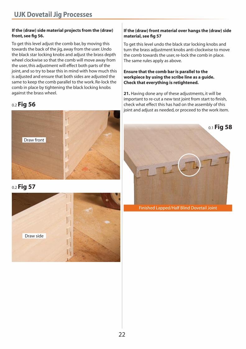
17. With the comb bar is removed it shows the two boards held in the jig having been cut in the offsetposition, see fig 54-55.
0.2 Fig 54-55
18. Remove the two boards from the jig and assemble them. 19. Check how the two boards fit together, it is now possible to adjust the tightness of the joint fit, this will require a small amount of adjustment to the cutterdepth ,and is best achieved using the fine height adjuster on the router. This adjustment affects bothparts of the joint as they are cut at the same time. The density of material that is being used will play a part in this as a hard brittle wood like, oak will not compress when pushed together, unlike pine which will compress when the boards are assembled. If the resulting joint is too loose when fitted together then lower the depth of the router cutter. If the resulting test joint is too tight then raise the cutter height, this will need doing carefully withsmall adjustments as it affects both parts. 20. The other important aim of the test fit of the joint is to check how the two boards meet on the outer face. This can be adjusted by moving the comb bar forward or back on the jig.
Back Cut
Curved contour
UJK Dovetail Jig Processes
22
To get this level adjust the comb bar, by moving this towards the back of the jig, away from the user. Undo the black star locking knobs and adjust the brass depth wheel clockwise so that the comb will move away from the user, this adjustment will effect both parts of the joint, and so try to bear this in mind with how much this is adjusted and ensure that both sides are adjusted the same to keep the comb parallel to the work. Re-lock the comb in place by tightening the black locking knobs against the brass wheel.
0.2 Fig 56
0.2 Fig 57
Draw front
Draw side
To get this level undo the black star locking knobs and turn the brass adjustment knobs anti-clockwise to move the comb towards the user, re-lock the comb in place. The same rules apply as above.
Ensure that the comb bar is parallel to the workpiece by using the scribe line as a guide. Check that everything is retightened.
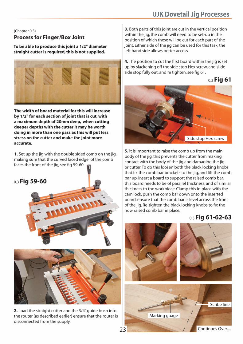
21. Having done any of these adjustments, it will be important to re-cut a new test joint from start to finish, check what effect this has had on the assembly of this joint and adjust as needed, or proceed to the work item.
Finished Lapped/Half Blind Dovetail Joint
0.1 Fig 58
If the (draw) side material projects from the (draw) front, see fig 56.
If the (draw) front material over hangs the (draw) side material, see fig 57
UJK Dovetail Jig Processes
23
(Chapter 0.3)
Process for Finger/Box Joint
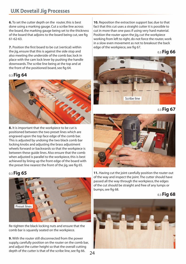
The width of board material for this will increase by 1/2" for each section of joint that is cut, with a maximum depth of 20mm deep, when cutting deeper depths with the cutter it may be worth doing in more than one pass as this will put less stress on the cutter and make the joint more accurate. 1. Set up the jig with the double sided comb on the jig, making sure that the curved faced edge of the comb faces the front of the jig, see fig 59-60.
0.3 Fig 59-60
2. Load the straight cutter and the 3/4” guide bush into the router (as described earlier) ensure that the router is disconnected from the supply.
0.3 Fig 61
Side stop Hex screw
5. It is important to raise the comb up from the main body of the jig, this prevents the cutter from making contact with the body of the jig and damaging the jig or cutter. To do this loosen both the black locking knobs that fix the comb bar brackets to the jig, and lift the comb bar up. Insert a board to support the raised comb bar, this board needs to be of parallel thickness, and of similar thickness to the workpiece. Clamp this in place with the cam lock, push the comb bar down onto the inserted board, ensure that the comb bar is level across the front of the jig. Re-tighten the black locking knobs to fix the now raised comb bar in place.
0.3 Fig 61-62-63
Marking guage
Scribe line
3. Both parts of this joint are cut in the vertical position within the jig, the comb will need to be set-up in the position of which these will be cut for each part of the joint. Either side of the jig can be used for this task, the left hand side allows better access. 4. The position to cut the first board within the jig is set up by slackening off the side stop Hex screw, and slide side stop fully out, and re tighten, see fig 61.
Continues Over....
To be able to produce this joint a 1/2" diameter straight cutter is required, this is not supplied.
UJK Dovetail Jig Processes
24
8. It is important that the workpiece to be cut is positioned between the two preset lines which are engraved upon the top face edge of the comb bar. This is adjusted by undoing the two black comb bar locking knobs and adjusting the brass adjustment wheels forward or backwards so that the workpiece is between these guide lines. Also ensure that the comb when adjusted is parallel to the workpiece, this is best achieved by lining up the front edge of the board with the preset line nearest the front of the jig, see fig 65.
0.3 Fig 65
Re-tighten the black locking nuts and ensure that the comb bar is squarely seated on the workpiece. 9. With the router still disconnected from the power supply, carefully position on the router on the comb bar, and adjust the cutter height so that the overall cutting depth of the cutter is that of the scribe line, see fig 66.
Preset lines
0.3 Fig 66
Scribe line
11. Having cut the joint carefully position the router out of the way and inspect the joint. The cutter should have passed all the way through the workpiece, the edges of the cut should be straight and free of any lumps or bumps, see fig 68.
0.3 Fig 67
0.3 Fig 68
6. To set the cutter depth on the router, this is bestdone using a marking gauge. Cut a scribe line acrossthe board, the marking gauge being set to the thickness of the board that adjoins to the board being cut, see fig61-62-63. 7. Position the first board to be cut (vertical) within the jig, ensure that this is against the side stop andalso meeting the underside of the comb bar, lock inplace with the cam lock lever by pushing the handle downwards. The scribe line being at the top and atthe front of the positioned board, see fig 64.
0.3 Fig 64
10. Reposition the extraction support bar, due to that fact that this cut uses a straight cutter it is possible to cut in more than one pass if using very hard material. Position the router upon the jig, cut the workpiece working from left to right, do not force the router, work in a slow even movement as not to breakout the back edge of the workpiece, see fig 67.
UJK Dovetail Jig Processes
25 Continues Over....
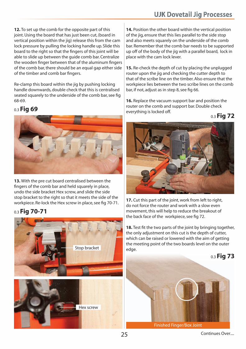
12. To set up the comb for the opposite part of this joint. Using the board that has just been cut, (board in vertical position within the jig) release this from the cam lock pressure by pulling the locking handle up. Slide this board to the right so that the fingers of this joint will be able to slide up between the guide comb bar. Centralize the wooden finger between that of the aluminum fingers of the comb bar, there should be an equal gap either side of the timber and comb bar fingers. Re-clamp this board within the jig by pushing locking handle downwards, double check that this is centralised seated squarely to the underside of the comb bar, see fig 68-69.
0.3 Fig 69
13. With the pre cut board centralised between the fingers of the comb bar and held squarely in place, undo the side bracket Hex screw, and slide the side stop bracket to the right so that it meets the side of the workpiece. Re-lock the Hex screw in place, see fig 70-71.
0.3 Fig 70-71
Stop bracket
Hex screw
14. Position the other board within the vertical position of the jig, ensure that this lies parallel to the side stop and also meets squarely on the underside of the comb bar. Remember that the comb bar needs to be supported up off of the body of the jig with a parallel board, lock in place with the cam lock lever. 15. Re-check the depth of cut by placing the unplugged router upon the jig and checking the cutter depth to that of the scribe line on the timber. Also ensure that the workpiece lies between the two scribe lines on the comb bar, if not, adjust as in step 8, see fig 66.
16. Replace the vacuum support bar and position the router on the comb and support bar. Double check everything is locked off.
17. Cut this part of the joint, work from left to right, do not force the router and work with a slow even movement, this will help to reduce the breakout ofthe back face of the workpiece, see fig 72. 18. Test fit the two parts of the joint by bringing together, the only adjustment on this cut is the depth of cutter, which can be raised or lowered with the aim of getting the meeting point of the two boards level on the outer edge.
0.3 Fig 72
Finished Finger/Box Joint
0.3 Fig 73
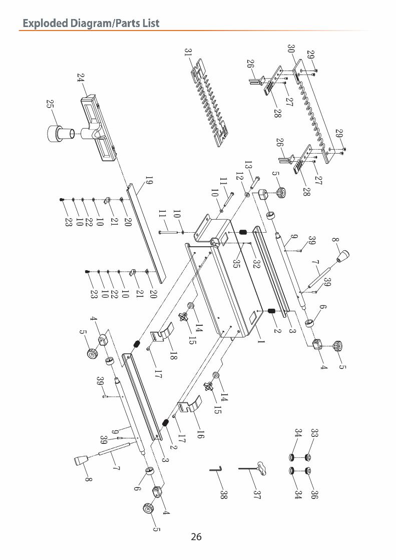
Exploded Diagram/Parts List
26

Exploded Diagram/Parts List
27
No Part No Description Qty
1 DJA1-9B BASE 1
2 4212-21 SPRING 4
3 DJA1-14B CLAMP BAR 2
4 4212-17 CLAMP ROD BLOCK 4
5 H211014000011Z KNOB 4
6 4212-16 CLAMP ROD CAM 4
7 DJA1-16B CLAMP ROD LEVER 2
8 G259038000071D KNOB 2
9 DJA1-15B CLAMP ROD 2
10 E0113060101Z WASHER 10
11 A201014300011Z HEX HEAD SCREW 4
12 E0118100151Z WASHER 2
13 A201038212011Z HEX HEAD SCREW 2
14 4212-4 BRASS THUMB WHEEL 2
15 142232-01 KNOB 2
16 DJA1-11B RIGHT OFFSET GUIDE 1
17 A206014012031D RND HD SCREW 2
18 DJA1-10B LEFT OFFSET GUIDE 1
19 DJA1-1 STABILIZER BAR 1
20 D235014000011Z SLIDING NUT 4
21 DJA1-17 LOCK KNOB 2
22 E0811060033D SPRING WASHER 2
23 A211014038031D SCREW 2
24 DJA1-7 DUST COLLECTOR 1
25 DJA1-6 REDUCER 1
26 DJA1-3 TEMPLATE BRACKET 2
27 A108005010011Z SCREW 4
28 DJA1-2 TEMPLATE BAR 2
29 A110006012031D SCREW 4
30 DJA1-4 HALF-BLIND TEMPLATE 1
31 DJA1-5 DOVETAIL TEMPLATE 1
32 F152006023011Z KNOB 1
33 DE6212-XJ-13 TEMPLATE GUIDE-3/4”OD 1
34 DE6212-XJ-14 LOCK NUT 2
35 D101006000011D SLIDING NUT 1
36 DE6212-XJ-15 TEMPLATE GUIDE-5/8”OD 1
37 4212-32 T-HANDLE HEX WRENCH 1
38 61-5-Z L-HEX WRENCH 1
39 A206010012032D RND HD SCREW 4

Notes
28

Notes
29

Notes
30

Notes
31
Axminster Tools & Machinery LtdWeycroft Avenue, Axminster, Devon EX13 5PH
ujktechnology.co.uk
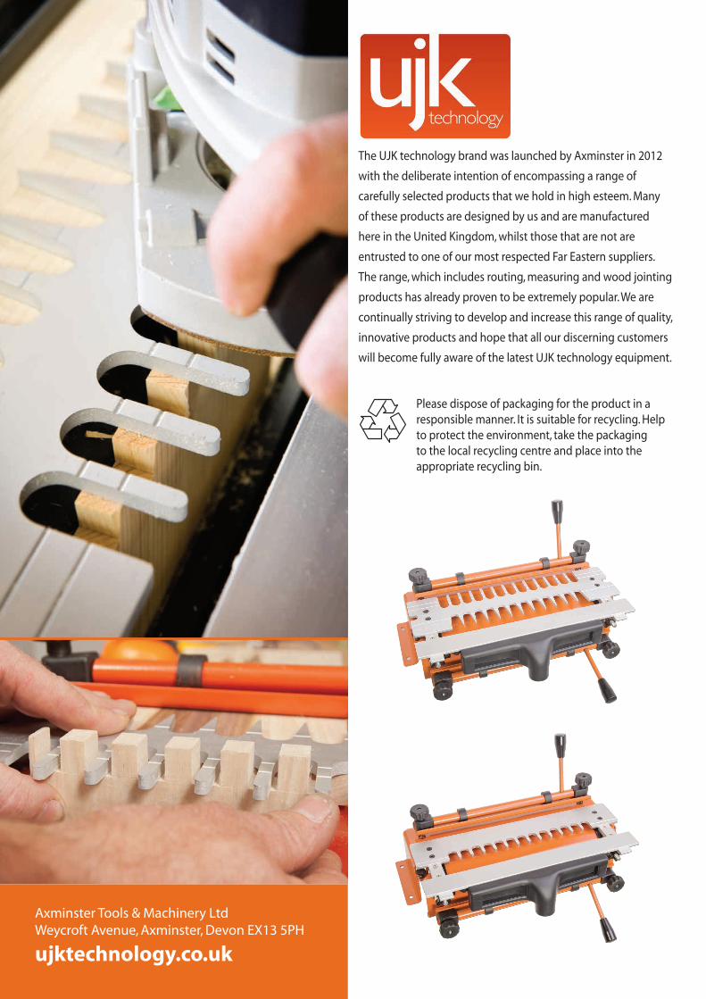
Please dispose of packaging for the product in a responsible manner. It is suitable for recycling. Help to protect the environment, take the packaging to the local recycling centre and place into the appropriate recycling bin.
The UJK technology brand was launched by Axminster in 2012
with the deliberate intention of encompassing a range of
carefully selected products that we hold in high esteem. Many
of these products are designed by us and are manufactured
here in the United Kingdom, whilst those that are not are
entrusted to one of our most respected Far Eastern suppliers.
The range, which includes routing, measuring and wood jointing
products has already proven to be extremely popular. We are
continually striving to develop and increase this range of quality,
innovative products and hope that all our discerning customers
will become fully aware of the latest UJK technology equipment.