Double-lok - Metl-Span
94
DOUBLE-LOK ® TECHNICAL/INSTALLATION INFORMATION
Transcript of Double-lok - Metl-Span

Double-lok®
Technical/insTallaTion informaTion
Descriptions and specifications contained herein were in effect at the time this publication was approved for printing. In a continuing effort to refine and improve products, Metl-Span reserves the right to discontinue products at any time or change specifications and/or designs without incurring obligation. To ensure you have the latest information available, please inquire or visit our website at www.metlspan.com. Application details are for illustration purposes only and may not be appropriate for all environmental conditions, building designs or panel profiles. Projects should be designed to conform to applicable building codes, regulations and accepted industry practices. If there is a conflict between this manual and project erection drawings, the erection drawings will take precedence.
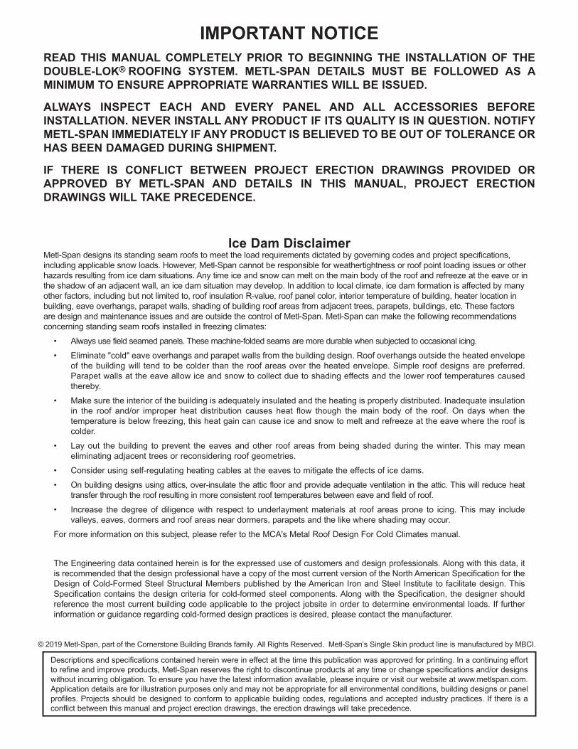
IMPORTANT NOTICEREAD THIS MANUAL COMPLETELY PRIOR TO BEGINNING THE INSTALLATION OF THE DOUBLE-LOk® ROOFING SYSTEM. METL-SPAN DETAILS MUST BE FOLLOWED AS A MINIMUM TO ENSURE APPROPRIATE WARRANTIES WILL BE ISSUED.
ALWAYS INSPECT EACH AND EVERY PANEL AND ALL ACCESSORIES BEFORE INSTALLATION. NEVER INSTALL ANY PRODUCT IF ITS QUALITY IS IN QUESTION. NOTIFY METL-SPAN IMMEDIATELY IF ANY PRODUCT IS BELIEVED TO BE OUT OF TOLERANCE OR HAS BEEN DAMAGED DURING SHIPMENT.
IF THERE IS CONFLICT BETWEEN PROJECT ERECTION DRAWINGS PROVIDED OR APPROVED BY METL-SPAN AND DETAILS IN THIS MANUAL, PROJECT ERECTION DRAWINGS WILL TAkE PRECEDENCE.
Ice Dam DisclaimerMetl-Span designs its standing seam roofs to meet the load requirements dictated by governing codes and project specifications, including applicable snow loads. However, Metl-Span cannot be responsible for weathertightness or roof point loading issues or other hazards resulting from ice dam situations. Any time ice and snow can melt on the main body of the roof and refreeze at the eave or in the shadow of an adjacent wall, an ice dam situation may develop. In addition to local climate, ice dam formation is affected by many other factors, including but not limited to, roof insulation R-value, roof panel color, interior temperature of building, heater location in building, eave overhangs, parapet walls, shading of building roof areas from adjacent trees, parapets, buildings, etc. These factors are design and maintenance issues and are outside the control of Metl-Span. Metl-Span can make the following recommendations concerning standing seam roofs installed in freezing climates:
• Alwaysusefieldseamedpanels.Thesemachine-foldedseamsaremoredurablewhensubjectedtooccasionalicing.
• Eliminate"cold"eaveoverhangsandparapetwallsfromthebuildingdesign.Roofoverhangsoutsidetheheatedenvelopeof the building will tend to be colder than the roof areas over the heated envelope. Simple roof designs are preferred.Parapet walls at the eave allow ice and snow to collect due to shading effects and the lower roof temperatures causedthereby.
• Makesuretheinteriorofthebuildingisadequatelyinsulatedandtheheatingisproperlydistributed.Inadequateinsulationin the roof and/or improper heat distribution causes heat flow though the main body of the roof. On days when thetemperature is below freezing, this heat gain can cause ice and snow to melt and refreeze at the eave where the roof iscolder.
• Layout thebuilding toprevent theeavesandother roofareas frombeingshadedduring thewinter.Thismaymeaneliminating adjacent trees or reconsidering roof geometries.
• Considerusingself-regulatingheatingcablesattheeavestomitigatetheeffectsoficedams.
• Onbuildingdesignsusingattics,over-insulatetheatticfloorandprovideadequateventilationintheattic.Thiswillreduceheattransfer through the roof resulting in more consistent roof temperatures between eave and field of roof.
• Increase thedegreeof diligencewith respect to underlaymentmaterials at roof areasprone to icing.Thismay includevalleys, eaves, dormers and roof areas near dormers, parapets and the like where shading may occur.
Formoreinformationonthissubject,pleaserefertotheMCA'sMetalRoofDesignForColdClimatesmanual.
TheEngineeringdatacontainedhereinisfortheexpresseduseofcustomersanddesignprofessionals.Alongwiththisdata,itis recommended that the design professional have a copy of the most current version of the North American Specification for the DesignofCold-FormedSteelStructuralMemberspublishedbytheAmericanIronandSteel Institutetofacilitatedesign.ThisSpecification contains the design criteria for cold-formed steel components. Along with the Specification, the designer should reference the most current building code applicable to the project jobsite in order to determine environmental loads. If further information or guidance regarding cold-formed design practices is desired, please contact the manufacturer.
© 2019 Metl-Span, part of the Cornerstone Building Brands family. All Rights Reserved. Metl-Span’sSingleSkinproductlineismanufacturedbyMBCI.
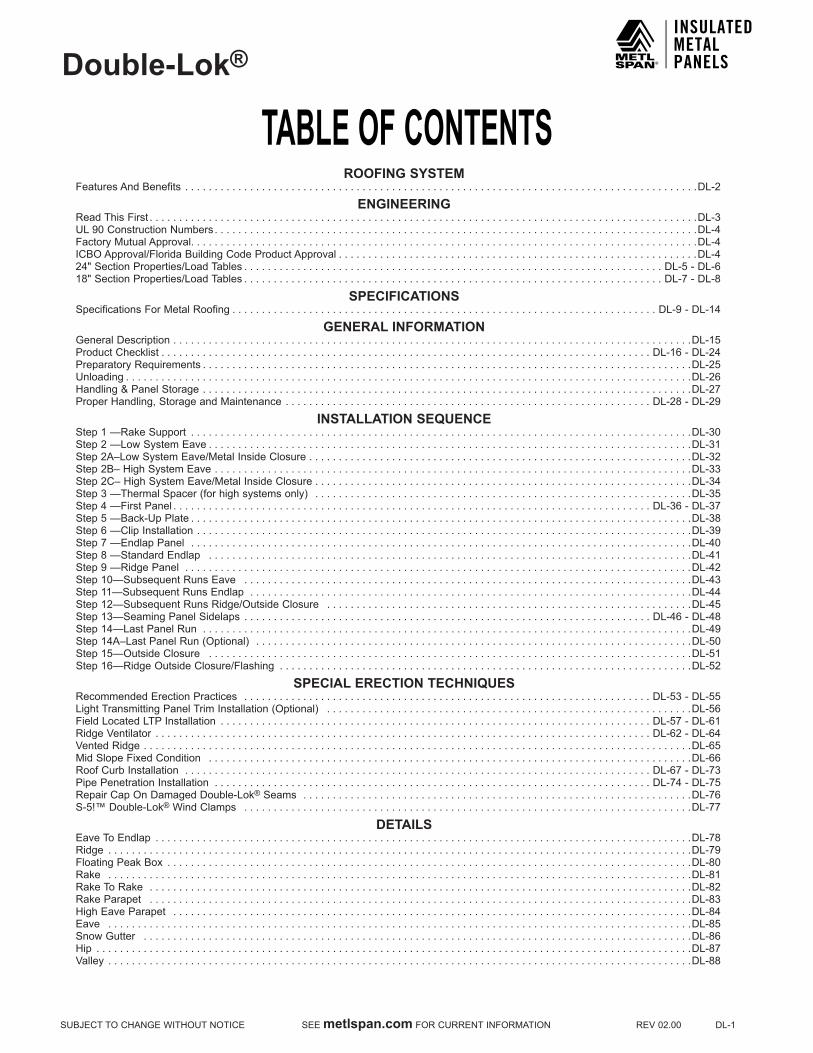
TABLE OF CONTENTSDouble-Lok®
SUBJECTTOCHANGEWITHOUTNOTICESEEmetlspan.comFORCURRENTINFORMATIONREV02.00DL-1
ROOFING SYSTEMFeaturesAndBenefits . . . . . . . . . . . . . . . . . . . . . . . . . . . . . . . . . . . . . . . . . . . . . . . . . . . . . . . . . . . . . . . . . . . . . . . . . . . . . . . . . . . . . . .DL-2
ENGINEERINGRead This First . . . . . . . . . . . . . . . . . . . . . . . . . . . . . . . . . . . . . . . . . . . . . . . . . . . . . . . . . . . . . . . . . . . . . . . . . . . . . . . . . . . . . . . . . . . . .DL-3UL90ConstructionNumbers . . . . . . . . . . . . . . . . . . . . . . . . . . . . . . . . . . . . . . . . . . . . . . . . . . . . . . . . . . . . . . . . . . . . . . . . . . . . . . . . . .DL-4Factory Mutual Approval. . . . . . . . . . . . . . . . . . . . . . . . . . . . . . . . . . . . . . . . . . . . . . . . . . . . . . . . . . . . . . . . . . . . . . . . . . . . . . . . . . . . . .DL-4ICBOApproval/FloridaBuildingCodeProductApproval . . . . . . . . . . . . . . . . . . . . . . . . . . . . . . . . . . . . . . . . . . . . . . . . . . . . . . . . . . . . .DL-424"SectionProperties/LoadTables . . . . . . . . . . . . . . . . . . . . . . . . . . . . . . . . . . . . . . . . . . . . . . . . . . . . . . . . . . . . . . . . . . . . . . . DL-5-DL-618"SectionProperties/LoadTables . . . . . . . . . . . . . . . . . . . . . . . . . . . . . . . . . . . . . . . . . . . . . . . . . . . . . . . . . . . . . . . . . . . . . . . DL-7-DL-8
SPECIFICATIONSSpecifications For Metal Roofing . . . . . . . . . . . . . . . . . . . . . . . . . . . . . . . . . . . . . . . . . . . . . . . . . . . . . . . . . . . . . . . . . . . . . . . . DL-9-DL-14
GENERAL INFORMATIONGeneralDescription . . . . . . . . . . . . . . . . . . . . . . . . . . . . . . . . . . . . . . . . . . . . . . . . . . . . . . . . . . . . . . . . . . . . . . . . . . . . . . . . . . . . . . . .DL-15ProductChecklist . . . . . . . . . . . . . . . . . . . . . . . . . . . . . . . . . . . . . . . . . . . . . . . . . . . . . . . . . . . . . . . . . . . . . . . . . . . . . . . . . . . DL-16-DL-24Preparatory Requirements . . . . . . . . . . . . . . . . . . . . . . . . . . . . . . . . . . . . . . . . . . . . . . . . . . . . . . . . . . . . . . . . . . . . . . . . . . . . . . . . . . .DL-25Unloading . . . . . . . . . . . . . . . . . . . . . . . . . . . . . . . . . . . . . . . . . . . . . . . . . . . . . . . . . . . . . . . . . . . . . . . . . . . . . . . . . . . . . . . . . . . . . . . .DL-26Handling & Panel Storage . . . . . . . . . . . . . . . . . . . . . . . . . . . . . . . . . . . . . . . . . . . . . . . . . . . . . . . . . . . . . . . . . . . . . . . . . . . . . . . . . . .DL-27Proper Handling, Storage and Maintenance . . . . . . . . . . . . . . . . . . . . . . . . . . . . . . . . . . . . . . . . . . . . . . . . . . . . . . . . . . . . . . DL-28-DL-29
INSTALLATION SEQUENCEStep1—RakeSupport . . . . . . . . . . . . . . . . . . . . . . . . . . . . . . . . . . . . . . . . . . . . . . . . . . . . . . . . . . . . . . . . . . . . . . . . . . . . . . . . . . . . .DL-30Step2—LowSystemEave . . . . . . . . . . . . . . . . . . . . . . . . . . . . . . . . . . . . . . . . . . . . . . . . . . . . . . . . . . . . . . . . . . . . . . . . . . . . . . . . . .DL-31Step2A–LowSystemEave/MetalInsideClosure . . . . . . . . . . . . . . . . . . . . . . . . . . . . . . . . . . . . . . . . . . . . . . . . . . . . . . . . . . . . . . . . .DL-32Step2B–HighSystemEave . . . . . . . . . . . . . . . . . . . . . . . . . . . . . . . . . . . . . . . . . . . . . . . . . . . . . . . . . . . . . . . . . . . . . . . . . . . . . . . . .DL-33Step2C–HighSystemEave/MetalInsideClosure . . . . . . . . . . . . . . . . . . . . . . . . . . . . . . . . . . . . . . . . . . . . . . . . . . . . . . . . . . . . . . . .DL-34Step3—ThermalSpacer(forhighsystemsonly) . . . . . . . . . . . . . . . . . . . . . . . . . . . . . . . . . . . . . . . . . . . . . . . . . . . . . . . . . . . . . . . .DL-35Step4—FirstPanel . . . . . . . . . . . . . . . . . . . . . . . . . . . . . . . . . . . . . . . . . . . . . . . . . . . . . . . . . . . . . . . . . . . . . . . . . . . . . . . . . DL-36-DL-37Step5—Back-UpPlate . . . . . . . . . . . . . . . . . . . . . . . . . . . . . . . . . . . . . . . . . . . . . . . . . . . . . . . . . . . . . . . . . . . . . . . . . . . . . . . . . . . . .DL-38Step6—ClipInstallation . . . . . . . . . . . . . . . . . . . . . . . . . . . . . . . . . . . . . . . . . . . . . . . . . . . . . . . . . . . . . . . . . . . . . . . . . . . . . . . . . . . .DL-39Step7—EndlapPanel . . . . . . . . . . . . . . . . . . . . . . . . . . . . . . . . . . . . . . . . . . . . . . . . . . . . . . . . . . . . . . . . . . . . . . . . . . . . . . . . . . . . .DL-40Step8—StandardEndlap . . . . . . . . . . . . . . . . . . . . . . . . . . . . . . . . . . . . . . . . . . . . . . . . . . . . . . . . . . . . . . . . . . . . . . . . . . . . . . . . . .DL-41Step9—RidgePanel . . . . . . . . . . . . . . . . . . . . . . . . . . . . . . . . . . . . . . . . . . . . . . . . . . . . . . . . . . . . . . . . . . . . . . . . . . . . . . . . . . . . . .DL-42Step10—SubsequentRunsEave . . . . . . . . . . . . . . . . . . . . . . . . . . . . . . . . . . . . . . . . . . . . . . . . . . . . . . . . . . . . . . . . . . . . . . . . . . . .DL-43Step11—SubsequentRunsEndlap . . . . . . . . . . . . . . . . . . . . . . . . . . . . . . . . . . . . . . . . . . . . . . . . . . . . . . . . . . . . . . . . . . . . . . . . . . .DL-44Step12—SubsequentRunsRidge/OutsideClosure . . . . . . . . . . . . . . . . . . . . . . . . . . . . . . . . . . . . . . . . . . . . . . . . . . . . . . . . . . . . . .DL-45Step13—SeamingPanelSidelaps . . . . . . . . . . . . . . . . . . . . . . . . . . . . . . . . . . . . . . . . . . . . . . . . . . . . . . . . . . . . . . . . . . . . . DL-46-DL-48Step14—LastPanelRun . . . . . . . . . . . . . . . . . . . . . . . . . . . . . . . . . . . . . . . . . . . . . . . . . . . . . . . . . . . . . . . . . . . . . . . . . . . . . . . . . . .DL-49Step14A–LastPanelRun(Optional) . . . . . . . . . . . . . . . . . . . . . . . . . . . . . . . . . . . . . . . . . . . . . . . . . . . . . . . . . . . . . . . . . . . . . . . . . .DL-50Step15—OutsideClosure . . . . . . . . . . . . . . . . . . . . . . . . . . . . . . . . . . . . . . . . . . . . . . . . . . . . . . . . . . . . . . . . . . . . . . . . . . . . . . . . . .DL-51Step16—RidgeOutsideClosure/Flashing . . . . . . . . . . . . . . . . . . . . . . . . . . . . . . . . . . . . . . . . . . . . . . . . . . . . . . . . . . . . . . . . . . . . . .DL-52
SPECIAL ERECTION TECHNIQUESRecommendedErectionPractices . . . . . . . . . . . . . . . . . . . . . . . . . . . . . . . . . . . . . . . . . . . . . . . . . . . . . . . . . . . . . . . . . . . . . DL-53-DL-55LightTransmittingPanelTrimInstallation(Optional) . . . . . . . . . . . . . . . . . . . . . . . . . . . . . . . . . . . . . . . . . . . . . . . . . . . . . . . . . . . . . .DL-56FieldLocatedLTPInstallation . . . . . . . . . . . . . . . . . . . . . . . . . . . . . . . . . . . . . . . . . . . . . . . . . . . . . . . . . . . . . . . . . . . . . . . . . DL-57-DL-61RidgeVentilator . . . . . . . . . . . . . . . . . . . . . . . . . . . . . . . . . . . . . . . . . . . . . . . . . . . . . . . . . . . . . . . . . . . . . . . . . . . . . . . . . . . . DL-62-DL-64VentedRidge . . . . . . . . . . . . . . . . . . . . . . . . . . . . . . . . . . . . . . . . . . . . . . . . . . . . . . . . . . . . . . . . . . . . . . . . . . . . . . . . . . . . . . . . . . . . .DL-65MidSlopeFixedCondition . . . . . . . . . . . . . . . . . . . . . . . . . . . . . . . . . . . . . . . . . . . . . . . . . . . . . . . . . . . . . . . . . . . . . . . . . . . . . . . . . .DL-66RoofCurbInstallation . . . . . . . . . . . . . . . . . . . . . . . . . . . . . . . . . . . . . . . . . . . . . . . . . . . . . . . . . . . . . . . . . . . . . . . . . . . . . . . DL-67-DL-73Pipe Penetration Installation . . . . . . . . . . . . . . . . . . . . . . . . . . . . . . . . . . . . . . . . . . . . . . . . . . . . . . . . . . . . . . . . . . . . . . . . . . DL-74-DL-75RepairCapOnDamagedDouble-Lok® Seams . . . . . . . . . . . . . . . . . . . . . . . . . . . . . . . . . . . . . . . . . . . . . . . . . . . . . . . . . . . . . . . . . .DL-76S-5!™Double-Lok®WindClamps . . . . . . . . . . . . . . . . . . . . . . . . . . . . . . . . . . . . . . . . . . . . . . . . . . . . . . . . . . . . . . . . . . . . . . . . . . . .DL-77
DETAILSEaveToEndlap . . . . . . . . . . . . . . . . . . . . . . . . . . . . . . . . . . . . . . . . . . . . . . . . . . . . . . . . . . . . . . . . . . . . . . . . . . . . . . . . . . . . . . . . . . .DL-78Ridge . . . . . . . . . . . . . . . . . . . . . . . . . . . . . . . . . . . . . . . . . . . . . . . . . . . . . . . . . . . . . . . . . . . . . . . . . . . . . . . . . . . . . . . . . . . . . . . . . . .DL-79FloatingPeakBox . . . . . . . . . . . . . . . . . . . . . . . . . . . . . . . . . . . . . . . . . . . . . . . . . . . . . . . . . . . . . . . . . . . . . . . . . . . . . . . . . . . . . . . . .DL-80Rake . . . . . . . . . . . . . . . . . . . . . . . . . . . . . . . . . . . . . . . . . . . . . . . . . . . . . . . . . . . . . . . . . . . . . . . . . . . . . . . . . . . . . . . . . . . . . . . . . . .DL-81Rake To Rake . . . . . . . . . . . . . . . . . . . . . . . . . . . . . . . . . . . . . . . . . . . . . . . . . . . . . . . . . . . . . . . . . . . . . . . . . . . . . . . . . . . . . . . . . . . .DL-82Rake Parapet . . . . . . . . . . . . . . . . . . . . . . . . . . . . . . . . . . . . . . . . . . . . . . . . . . . . . . . . . . . . . . . . . . . . . . . . . . . . . . . . . . . . . . . . . . . .DL-83HighEaveParapet . . . . . . . . . . . . . . . . . . . . . . . . . . . . . . . . . . . . . . . . . . . . . . . . . . . . . . . . . . . . . . . . . . . . . . . . . . . . . . . . . . . . . . . .DL-84Eave . . . . . . . . . . . . . . . . . . . . . . . . . . . . . . . . . . . . . . . . . . . . . . . . . . . . . . . . . . . . . . . . . . . . . . . . . . . . . . . . . . . . . . . . . . . . . . . . . . .DL-85SnowGutter . . . . . . . . . . . . . . . . . . . . . . . . . . . . . . . . . . . . . . . . . . . . . . . . . . . . . . . . . . . . . . . . . . . . . . . . . . . . . . . . . . . . . . . . . . . . .DL-86Hip . . . . . . . . . . . . . . . . . . . . . . . . . . . . . . . . . . . . . . . . . . . . . . . . . . . . . . . . . . . . . . . . . . . . . . . . . . . . . . . . . . . . . . . . . . . . . . . . . . . . .DL-87Valley . . . . . . . . . . . . . . . . . . . . . . . . . . . . . . . . . . . . . . . . . . . . . . . . . . . . . . . . . . . . . . . . . . . . . . . . . . . . . . . . . . . . . . . . . . . . . . . . . . .DL-88

ROOFING SYSTEM
DL-2 REV02.00 SEEmetlspan.comFORCURRENTINFORMATION SUBJECTTOCHANGEWITHOUTNOTICE
CAUTIONApplication and design details are for illustration purposes only, and may not be appropriate for all environmental conditions or building designs. Projects should be engineered to conform to applicable building codes, regulations, and accepted industry practices.
FEATURES AND BENEFITS1. DESIGNINTEGRITY
Metl-Span’sDouble-Lok® mechanically seamed system begins and ends in the high, reducing the risk of leakage at the rake that can occur when finishing in the low. The panel seam includes factory-applied mastic.
2. FLOATINGROOFThe Double-Lok®roofwasdesignedtocopewiththeforcesofexpansionandcontraction.Thisisaccomplishedbyallowingthe panels to freely move up and down the roof slope.
3. SLIDINGCLIPS2"and4"SlidingClipsareavailable,with the2"versionproviding11/4"movement ineachdirectionwhile the4"versionprovidesfor2"ofmovementineachdirection.Bothclipsarealsoavailableinhighandlowversions,whichprovidesa3/8"clearanceora13/8" clearance, allowing for a variety of thermal spacer and insulation thickness combinations.
4. UL90RATINGThe Double-Lok®roofsystemhas7differentUL90constructionnumbers,eachofwhichisavailablewithseveraloptions.
5. FACTORYMUTUALAPPROVALThe Double-Lok®roofhasbeentestedbyFactoryMutualResearchCorporationforwinduplift,fireandhaildamageunderStandard4471achievingvariousratings.RefertopageDL-4forsummaryinformation.
6. FIRERESISTANCERATINGSTheroofsystemqualifiesforuseinseveralULdesignassembliesandcarriesaUL“ClassA”FireRating.
7. SIMPLICITYNo troublesome batten cap is needed. The panels simply seam together forming a watertight seal.
8. FLEXIBILITYMetl-Span’sDouble-Lok®roofsystemofferswelcomeflexibilitytotheerector.Wallcoveringcanbeerectedbeforeorafterthe roof is installed. Panel installation is an uninterrupted procedure.
9. EASEOFINSTALLATIONThe erector has the option to sheet each side of the roof separately or both sides simultaneously, which greatly increases thespeedandconvenienceoferection.Beingreversibleend-for-end,sheetsdonothavetobespecialorderedforeachside of the building. No field notching of panels at endlaps or ridge is required.
10. FORGIVINGSYSTEMThe Double-Lok® design allows for the roof to be finished in the high when an out-of-square condition or other factors cause therooftoterminateupto4"outofmodule.
11. BUILDINGLENGTHOdd,aswellaseven,footagebuildingscanbeterminatedinamajorribwiththeuseofour18"panelorinthelowbyfieldbending the panel.
12. PREPUNCHEDPANELSANDCOMPONENTSMetl-Span’sprepunchedsystem,combinedwithself-engagingback-upplates,assurespanelmoduleandspeedsuproofinstallation.
13. DURABILITYEvery unpainted panel is manufactured fromGalvalume Plus®, your assurance of the manufacturer's commitment toquality.
14. COLORANDFINISHESDouble-Lok® is available in a wide variety of popular colors in three different paint systems. Double-Lok®isaregisteredtrademarkofthe Cornerstone Building Brands family.Galvalume Plus®isaregisteredtrademarkofBIECInternational,Inc.Vise-Grip®isaregisteredtrademarkofAmericanToolCompanies,Inc.S-5!™ is a trademark of Metal Roof Innovations.
Double-Lok®
ENGINEERINGDouble-Lok®
SUBJECTTOCHANGEWITHOUTNOTICESEEmetlspan.comFORCURRENTINFORMATIONREV02.00DL-3
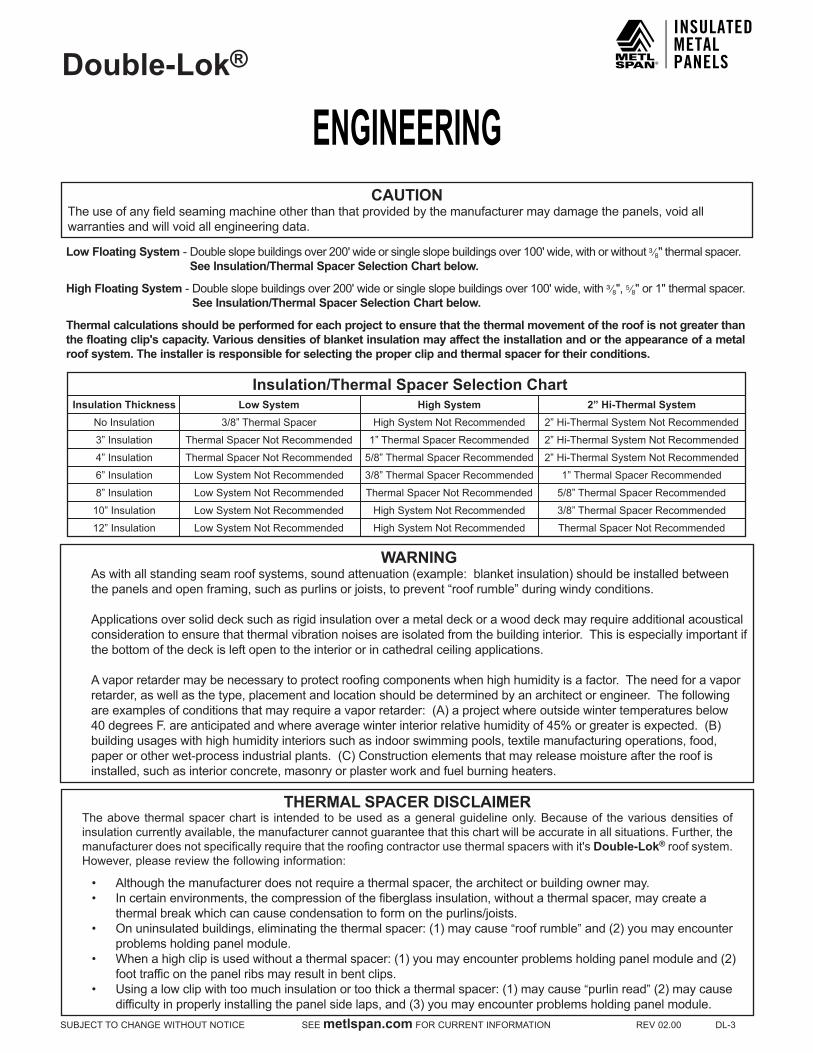
CAUTIONThe use of any field seaming machine other than that provided by the manufacturer may damage the panels, void all warranties and will void all engineering data.
Low Floating System-Doubleslopebuildingsover200'wideorsingleslopebuildingsover100'wide,withorwithout³ ⁄8"thermalspacer.See Insulation/Thermal Spacer Selection Chart below.
High Floating System-Doubleslopebuildingsover200'wideorsingleslopebuildingsover100'wide,with³ ⁄8",5⁄8"or1"thermalspacer.See Insulation/Thermal Spacer Selection Chart below.
Thermal calculations should be performed for each project to ensure that the thermal movement of the roof is not greater than the floating clip's capacity. Various densities of blanket insulation may affect the installation and or the appearance of a metal roof system. The installer is responsible for selecting the proper clip and thermal spacer for their conditions.
THERMAL SPACER DISCLAIMERTheabovethermalspacerchart is intendedtobeusedasageneralguidelineonly.Becauseof thevariousdensitiesofinsulation currently available, the manufacturer cannot guarantee that this chart will be accurate in all situations. Further, the manufacturerdoesnotspecificallyrequirethattheroofingcontractorusethermalspacerswithit'sDouble-Lok® roof system. However, please review the following information:
• Although the manufacturer does not require a thermal spacer, the architect or building owner may.• In certain environments, the compression of the fiberglass insulation, without a thermal spacer, may create a
thermal break which can cause condensation to form on the purlins/joists.• Onuninsulatedbuildings,eliminatingthethermalspacer:(1)maycause“roof rumble”and(2)youmayencounter
problems holding panel module.• Whenahighclipisusedwithoutathermalspacer:(1)youmayencounterproblemsholdingpanelmoduleand(2)
foot traffic on the panel ribs may result in bent clips.• Usingalowclipwithtoomuchinsulationortoothickathermalspacer:(1)maycause“purlin read”(2)maycause
difficultyinproperlyinstallingthepanelsidelaps,and(3)youmayencounterproblemsholdingpanelmodule.
WARNINGAswithallstandingseamroofsystems,soundattenuation(example:blanketinsulation)shouldbeinstalledbetweenthepanelsandopenframing,suchaspurlinsorjoists,toprevent“roofrumble”duringwindyconditions.
Applications over solid deck such as rigid insulation over a metal deck or a wood deck may require additional acoustical consideration to ensure that thermal vibration noises are isolated from the building interior. This is especially important if the bottom of the deck is left open to the interior or in cathedral ceiling applications.
A vapor retarder may be necessary to protect roofing components when high humidity is a factor. The need for a vapor retarder, as well as the type, placement and location should be determined by an architect or engineer. The following areexamplesofconditionsthatmayrequireavaporretarder:(A)aprojectwhereoutsidewintertemperaturesbelow40degreesF.areanticipatedandwhereaveragewinterinteriorrelativehumidityof45%orgreaterisexpected.(B)buildingusageswithhighhumidityinteriorssuchasindoorswimmingpools,textilemanufacturingoperations,food,paperorotherwet-processindustrialplants.(C)Constructionelementsthatmayreleasemoistureaftertheroofisinstalled, such as interior concrete, masonry or plaster work and fuel burning heaters.
Insulation/Thermal Spacer Selection ChartInsulation Thickness Low System High System 2” Hi-Thermal System
No Insulation 3/8” Thermal Spacer High System Not Recommended 2” Hi-Thermal System Not Recommended
3” Insulation Thermal Spacer Not Recommended 1” Thermal Spacer Recommended 2” Hi-Thermal System Not Recommended
4” Insulation Thermal Spacer Not Recommended 5/8” Thermal Spacer Recommended 2” Hi-Thermal System Not Recommended
6” Insulation Low System Not Recommended 3/8” Thermal Spacer Recommended 1” Thermal Spacer Recommended
8” Insulation Low System Not Recommended Thermal Spacer Not Recommended 5/8” Thermal Spacer Recommended
10” Insulation Low System Not Recommended High System Not Recommended 3/8” Thermal Spacer Recommended
12” Insulation Low System Not Recommended High System Not Recommended Thermal Spacer Not Recommended

ENGINEERINGDouble-Lok®
DL-4REV02.00SEEmetlspan.comFORCURRENTINFORMATIONSUBJECTTOCHANGEWITHOUTNOTICE
Construction Number
Panel Width (In.) Gauge Clip Type Substrate UL-2218
Impact Resistance UL-263
Fire RatingUL-580 Rating
165 24 24min. Sliding Open Framing Class4 ClassA Class90180C 24 24min. Sliding CompositeSystem Class4 ClassA Class90287 24 24min. Sliding Open Framing Class4 ClassA Class90308A 24 24min. Sliding CompositeSystem Class4 ClassA Class90450 24 24min. Sliding Open Framing Class4 ClassA Class90538 24 24min. Sliding Open Framing Class4 ClassA Class90539 24 24min. Sliding CompositeSystem Class4 ClassA Class90540 24 24min. Sliding CompositeSystem Class4 ClassA Class90
NOTES:1.TestsproceduresareinaccordancewithUnderwritersLaboratoriesStandardUL-580under“TestsForUpliftResistanceofRoofAssemblies”.
2.AdetailedinstallationmethodisavailableforeachConstructionNumberaboveandcanbefoundintheULRoofingMaterialsand Systems Directory. The panels must be installed in a certain manner to achieve the published results when installed over aClassAsubstructure.
3.ThepanelqualifiesforaClassAfireratingincompliancewithUnderwritersLaboratoriesStandardUL-263.4.ThepanelsystemislistedunderthefollowingFireResistanceDesignNumbers:P225,P227,P230,P237,P265,P268,P508,P510,P512,P701,P711,P717,P720,P722,P726,P731,P734,P801,P815,andP819.Refer to theULFireResistanceDirectory for specific construction methods and hourly ratings.
5.ConstructionNumber450includestheuseofadomedskylight.
FACTORY MUTUAL APPROVALDouble-Lok®
Panel Width Gauge Clip Type Clip
Spacing Substrate # of Fasteners per Clip
Wind Clamp per Clip
Hail Damage Rating
ASTM E108 Fire Rating
FM Windstorm Rating
24 24 2"Sliding 5'-0" Open Framing 2 n/a Class1-SH ClassA Class1-6024 24 2"Sliding 5'-0" Open Framing 2 1 Class1-SH ClassA Class1-7524 22 2"Sliding 5'-0" Open Framing 2 n/a Class1-SH ClassA Class1-7524 24 2"Sliding 5'-0" Open Framing 2 1 Class1-SH ClassA Class1-9024 22 2"Sliding 4'-0" Open Framing 2 n/a Class1-SH ClassA Class1-9018 24 2"Sliding 5'-0" Open Framing 2 n/a Class1-SH ClassA Class1-9024 22 2"Sliding 4'-0" Open Framing 2 n/a Class1-SH ClassA Class1-10524 22 2"Sliding 3'-6" Open Framing 2 n/a Class1-SH ClassA Class1-10524 22 4"Sliding 5'-0" Open Framing 3 1 Class1-SH ClassA Class1-12018 24 2"Sliding 5'-0" Open Framing 3 1 Class1-SH ClassA Class1-13524 22 4"Sliding 5'-0" Open Framing 3 2 Class1-SH ClassA Class1-150
NOTES:1.TestsproceduresareinaccordancewithFactoryMutualResearchCorporation(FMRC)Standard4471.2.Adetailedtestreportisavailableforeachproductabove.Thepanelsmustbeinstalledinaspecificmannertoachievethepublishedresults.Contactthemanufacturerformoreinformation.
FLORIDA BUILDING CODE PRODUCT APPROVALDouble-Lok®RoofingSystemdetailsandengineeringloadtableshavebeenexaminedbytheStateofFloridaandcomplywiththe2010FloridaBuildingCodeProductApprovalNumber(FL#11819.2).

ENGINEERINGDouble-Lok®
SUBJECTTOCHANGEWITHOUTNOTICESEEmetlspan.comFORCURRENTINFORMATIONREV02.00DL-5
SECTION PROPERTIESNEGATIVE BENDING POSITIVE BENDING
PANEL GAUGE
Fy (kSI)
WEIGHT (PSF)
Ixe (IN.4/FT.)
Sxe (IN.3/FT.)
Maxo (kIP-IN.)
Ixe (IN.4/FT.)
Sxe (IN.3/FT.)
Maxo (kIP-IN.)
24 50 1.23 0.1507 0.0989 2.9619 0.3224 0.1308 3.916622 50 1.56 0.2059 0.1394 4.1741 0.4205 0.1709 5.1171
NOTES:1.AllcalculationsforthepropertiesofDouble-Lok®panelsarecalculatedinaccordancewiththe2012Editionofthe
North American Specification For Design Of Cold-Formed Steel Structural Members.2.Ixeisfordeflectiondetermination.3.Sxeisforbending.4.Maxoisallowablebendingmoment.5.Allvaluesarefortheonefootofpanelwidth.
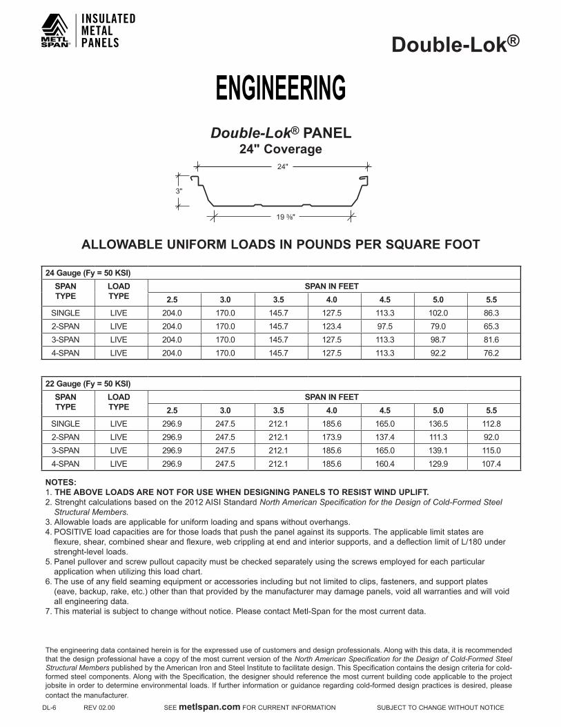
Double-Lok® PANEL24" Coverage
24"
3"
19 ³⁄₈"
Theengineeringdatacontainedhereinisfortheexpresseduseofcustomersanddesignprofessionals.Alongwiththisdata,itisrecommendedthat the design professional have a copy of the most current version of the North American Specification for the Design of Cold-Formed Steel Structural Members published by the American Iron and Steel Institute to facilitate design. This Specification contains the design criteria for cold-formed steel components. Along with the Specification, the designer should reference the most current building code applicable to the project jobsite in order to determine environmental loads. If further information or guidance regarding cold-formed design practices is desired, please contact the manufacturer.
ENGINEERINGDouble-Lok®
DL-6REV02.00SEEmetlspan.comFORCURRENTINFORMATIONSUBJECTTOCHANGEWITHOUTNOTICE
Double-Lok® PANEL24" Coverage
24"
3"
19 ³⁄₈"
ALLOWABLE UNIFORM LOADS IN POUNDS PER SQUARE FOOT
24 Gauge (Fy = 50 kSI)SPAN TYPE
LOAD TYPE
SPAN IN FEET2.5 3.0 3.5 4.0 4.5 5.0 5.5
SINGLE LIVE 204.0 170.0 145.7 127.5 113.3 102.0 86.32-SPAN LIVE 204.0 170.0 145.7 123.4 97.5 79.0 65.33-SPAN LIVE 204.0 170.0 145.7 127.5 113.3 98.7 81.64-SPAN LIVE 204.0 170.0 145.7 127.5 113.3 92.2 76.2
22 Gauge (Fy = 50 kSI)SPAN TYPE
LOAD TYPE
SPAN IN FEET2.5 3.0 3.5 4.0 4.5 5.0 5.5
SINGLE LIVE 296.9 247.5 212.1 185.6 165.0 136.5 112.82-SPAN LIVE 296.9 247.5 212.1 173.9 137.4 111.3 92.03-SPAN LIVE 296.9 247.5 212.1 185.6 165.0 139.1 115.04-SPAN LIVE 296.9 247.5 212.1 185.6 160.4 129.9 107.4
NOTES:1.THE ABOVE LOADS ARE NOT FOR USE WHEN DESIGNING PANELS TO RESIST WIND UPLIFT.2.Strenghtcalculationsbasedonthe2012AISIStandardNorth American Specification for the Design of Cold-Formed Steel Structural Members.3.Allowableloadsareapplicableforuniformloadingandspanswithoutoverhangs.4.POSITIVEloadcapacitiesareforthoseloadsthatpushthepanelagainstitssupports.Theapplicablelimitstatesare flexure,shear,combinedshearandflexure,webcripplingatendandinteriorsupports,andadeflectionlimitofL/180under strenght-level loads.5.Panelpulloverandscrewpulloutcapacitymustbecheckedseparatelyusingthescrewsemployedforeachparticular application when utilizing this load chart.6.Theuseofanyfieldseamingequipmentoraccessoriesincludingbutnotlimitedtoclips,fasteners,andsupportplates (eave,backup,rake,etc.)otherthanthatprovidedbythemanufacturermaydamagepanels,voidallwarrantiesandwillvoid all engineering data.7.Thismaterialissubjecttochangewithoutnotice.PleasecontactMetl-Spanforthemostcurrentdata.
Theengineeringdatacontainedhereinisfortheexpresseduseofcustomersanddesignprofessionals.Alongwiththisdata,itisrecommendedthat the design professional have a copy of the most current version of the North American Specification for the Design of Cold-Formed Steel Structural Members published by the American Iron and Steel Institute to facilitate design. This Specification contains the design criteria for cold-formed steel components. Along with the Specification, the designer should reference the most current building code applicable to the project jobsite in order to determine environmental loads. If further information or guidance regarding cold-formed design practices is desired, please contact the manufacturer.

ENGINEERINGDouble-Lok®
SUBJECTTOCHANGEWITHOUTNOTICESEEmetlspan.comFORCURRENTINFORMATIONREV02.00DL-7
SECTION PROPERTIESNEGATIVE BENDING POSITIVE BENDING
PANEL GAUGE
Fy (kSI)
WEIGHT (PSF)
Ixe (IN.4/FT.)
Sxe (IN.3/FT.)
Maxo (kIP-IN.)
Ixe (IN.4/FT.)
Sxe (IN.3/FT.)
Maxo (kIP-IN.)
24 50 1.32 0.1994 0.1313 3.9306 0.3814 0.1651 4.944922 50 1.66 0.2718 0.1846 5.5274 0.4968 0.2154 6.4494
NOTES:1.AllcalculationsforthepropertiesofDouble-Lok®panelsarecalculatedinaccordancewiththe2012Editionofthe
North American Specification For Design Of Cold-Formed Steel Structural Members.2.Ixeisfordeflectiondetermination.3.Sxeisforbending.4.Maxoisallowablebendingmoment.5.Allvaluesarefortheonefootofpanelwidth.
Double-Lok® PANEL18" Coverage
18"
3"
13 ³⁄₈"
Theengineeringdatacontainedhereinisfortheexpresseduseofcustomersanddesignprofessionals.Alongwiththisdata,itisrecommendedthat the design professional have a copy of the most current version of the North American Specification for the Design of Cold-Formed Steel Structural Members published by the American Iron and Steel Institute to facilitate design. This Specification contains the design criteria for cold-formed steel components. Along with the Specification, the designer should reference the most current building code applicable to the project jobsite in order to determine environmental loads. If further information or guidance regarding cold-formed design practices is desired, please contact the manufacturer.

ENGINEERINGDouble-Lok®
DL-8REV02.00SEEmetlspan.comFORCURRENTINFORMATIONSUBJECTTOCHANGEWITHOUTNOTICE
Double-Lok® PANEL18" Coverage
ALLOWABLE UNIFORM LOADS IN POUNDS PER SQUARE FOOT
24 Gauge (Fy = 50 kSI)SPAN TYPE
LOAD TYPE
SPAN IN FEET2.5 3.0 3.5 4.0 4.5 5.0 5.5
SINGLE LIVE 272.0 226.7 194.3 170.0 151.1 131.9 109.02-SPAN LIVE 272.0 226.7 194.3 163.8 129.4 104.8 86.63-SPAN LIVE 272.0 226.7 194.3 170.0 151.1 131.0 108.34-SPAN LIVE 272.0 226.7 194.3 170.0 151.0 122.3 101.1
22 Gauge (Fy = 50 kSI)SPAN TYPE
LOAD TYPE
SPAN IN FEET2.5 3.0 3.5 4.0 4.5 5.0 5.5
SINGLE LIVE 395.9 329.9 282.8 247.5 212.3 172.0 142.12-SPAN LIVE 395.9 329.9 282.8 230.3 182.0 147.4 121.83-SPAN LIVE 395.9 329.9 282.8 247.5 220.0 184.2 152.34-SPAN LIVE 395.9 329.9 282.8 247.5 212.4 172.0 142.2
NOTES:1.THE ABOVE LOADS ARE NOT FOR USE WHEN DESIGNING PANELS TO RESIST WIND UPLIFT.2.Strenghtcalculationsbasedonthe2012AISIStandardNorth American Specification for the Design of Cold-Formed Steel Structural Members.3.Allowableloadsareapplicableforuniformloadingandspanswithoutoverhangs.4.LIVEloadcapacitiesareforthoseloadsthatpushthepanelagainstitssupports.Theapplicablelimitstatesareflexure, shear,combinedshearandflexure,webcripplingatendandinteriorsupports,andadeflectionlimitofL/180under strenght-level loads.5.Panelpulloverandscrewpulloutcapacitymustbecheckedseparatelyusingthescrewsemployedforeachparticular application when utilizing this load chart.6.Theuseofanyfieldseamingequipmentoraccessoriesincludingbutnotlimitedtoclips,fasteners,andsupportplates (eave,backup,rake,etc.)otherthanthatprovidedbythemanufacturermaydamagepanels,voidallwarrantiesandwill void all engineering data.7.Thismaterialissubjecttochangewithoutnotice.PleasecontactMetl-Spanforthemostcurrentdata.
18"
3"
13 ³⁄₈"
Theengineeringdatacontainedhereinisfortheexpresseduseofcustomersanddesignprofessionals.Alongwiththisdata,itisrecommendedthat the design professional have a copy of the most current version of the North American Specification for the Design of Cold-Formed Steel Structural Members published by the American Iron and Steel Institute to facilitate design. This Specification contains the design criteria for cold-formed steel components. Along with the Specification, the designer should reference the most current building code applicable to the project jobsite in order to determine environmental loads. If further information or guidance regarding cold-formed design practices is desired, please contact the manufacturer.

SPECIFICATIONSDouble-Lok®
SUBJECTTOCHANGEWITHOUTNOTICESEEmetlspan.comFORCURRENTINFORMATIONREV02.00DL-9
SECTION 07 41 13 METAL ROOFING PANELS
PART 1 - GENERAL1.1 SECTION INCLUDES
A. Trapezoidal-rib, seamed joint, standing seam metal roof panels, with related metal trim and accessories.
1.2 RELATED REQUIREMENTSSpecifier: If retaining this optional article, edit list below to correspond to Project.
A. Division01Section"SustainableDesignRequirements"forrelatedLEEDgeneralrequirements.
B. Division05Section"StructuralSteelFraming"forstructural steel framing supporting metal panels.
C. Division05Section"SteelDecking"forcontinuousmetal decking supporting metal panels.
D. Division05Section"Cold-FormedMetalFraming"forcold-formed metal framing supporting metal panels.
E.Division05Section"Cold-FormedMetalTrusses"forcold-formed metal trusses supporting metal panels.
F. Division06Section"Sheathing"forsheathingsubstrate for metal roof panels.
G.Division07Section["ThermalInsulation"]["RoofInsulation"]forthermalinsulationinstalledundermetal panels.
H.Division07Section"AirBarriers"forairbarrierswithinroof assembly and adjacent to roof assembly.
I.Division07Section"MetalWallPanels"forfactory-formedmetalwall[andsoffit]panels.
J.Division07Section"SheetMetalFlashingandTrim"for formed sheet metal copings, flashings, reglets, and roof drainage items in addition to items specified in this Section.
K. Division07Section"ManufacturedRoofSpecialties"for manufactured copings, reglets, and roof drainage items in addition to items specified in this Section.
L. Division07Section"JointSealants"forfield-appliedjoint sealants.
M.Division13Section"MetalBuildingSystems"forsteelframing supporting metal panels.
1.3 REFERENCESSpecifier: If retaining this optional article, edit list below to correspond to Project.
A. AmericanArchitecturalManufacturer'sAssociation(AAMA):www.aamanet.org:1. AAMA621-VoluntarySpecificationsforHigh
PerformanceOrganicCoatingsonCoilCoatedArchitecturalHotDippedGalvanized(HDG)&Zinc-AluminumCoatedSteelSubstrates.
2. AAMA809.2-VoluntarySpecificationNon-DryingSealants.
B. AmericanSocietyofCivilEngineers(ASCE):www.asce.org/codes-standards: 1. ASCE7-MinimumDesignLoadsforBuildings
and Other Structures.C. ASTMInternational(ASTM):www.astm.org:
1. ASTMA653-SpecificationforSteelSheet,Zinc-Coated(Galvanized)orZinc-IronAlloy-Coated(Galvannealed)bytheHot-DipProcess.
2. ASTMA755-SpecificationforSteelSheet,MetallicCoatedbytheHot-DipProcessandPrepaintedbytheCoil-CoatingProcessforExteriorExposedBuildingProducts.
3. ASTMA792/A792M-StandardSpecificationforSteelSheet,55%Aluminum-ZincAlloy-Coatedbythe Hot-Dip Process.
4. ASTMA980-StandardSpecificationforSteel,Sheet,Carbon,UltraHighStrengthColdRolled.
5. ASTMC645-SpecificationforNonstructuralSteel Framing Members.
6. ASTMC920-SpecificationforElastomericJointSealants.
7. ASTMD1003-StandardTestMethodforHazeandLuminousTransmittanceofTransparentPlastics.
8. ASTMD2244-TestMethodforCalculationofColorDifferencesfromInstrumentallyMeasuredColorCoordinates.
9. ASTMD4214-TestMethodsforEvaluatingDegreeofChalkingofExteriorPaintFilms.
10.ASTME1514-StandardSpecificationforStructural Standing Seam Steel Roof Panel Systems.
11. ASTME1592-StandardTestMethodforStructural Performance of Sheet Metal Roof and Siding Systems by Uniform Static Air Pressure Difference.
12. ASTME1646-StandardTestMethodforWaterPenetrationofExteriorMetalRoofPanelSystemsby Uniform Static Air Pressure Difference.
13. ASTME1680-StandardTestMethodforRateofAirLeakageThroughExteriorMetalRoofPanelSystems.
14. ASTME1980-PracticeforCalculatingSolarReflectanceIndexofHorizontalandLow-SlopedOpaque Surfaces.
D. CoolRoofRatingCouncil(CRRC):www.coolroofs.org/productratingprogram.html: 1. CRRC-1-2008-CRRCProductRatingprogram.
E. FMGlobal(FM):www.fmglobal.com:1. ANSI/FM4471-ApprovalStandardforClass1
Panel Roofs.F. InternationalAccreditationService(IAS):
1. IASAC472-AccreditationCriteriaforInspection

SPECIFICATIONSDouble-Lok®
DL-10REV02.00SEEmetlspan.comFORCURRENTINFORMATIONSUBJECTTOCHANGEWITHOUTNOTICE
ProgramsforManufacturersofMetalBuildingSystems,PartB.
G.UnderwritersLaboratories,Inc.(UL):www.ul.com:1. UL580-TestsforUpliftResistanceofRoof
AssembliesH. USEnvironmentalProtectionAgency: www.energystar.gov/index.cfm:
1. EnergyStarReflectiveRoofProducts.I. USGreenBuildingCouncil(USGBC):www.usgbc.org:
1. LEED-LeadershipinEnergyandEnvironmentalDesign(LEED)GreenBuildingRatingSystems.
1.4 ADMINISTRATIVE REQUIREMENTSA. Preinstallation Meeting: Prior to erection of framing,
conduct preinstallation meeting at site attended by Owner,Architect,manufacturer'stechnicalrepresentative, inspection agency and related trade contractors.1. Coordinatebuildingframinginrelationtometal
panel system. 2. Coordinateopeningsandpenetrationsofmetal
panel system.3. CoordinateworkofDivision07Sections"Roof
Specialties"and"RoofAccessories"andopeningsandpenetrationsandmanufacturer'saccessorieswith installation of metal panels.
1.5 QUALITY ASSURANCEA. Manufacturer/Source: Provide metal roof panel
assembly and accessories from a single manufacturerprovidingfixed-baserollforming,andaccreditedunderIASAC472PartB.
B. ManufacturerQualifications:Approvedmanufacturerlisted in this Section with minimum five years experienceinmanufactureofsimilarproductsinsuccessful use in similar applications.
Specifier: Retain paragraph below if Owner allows substitutions but requires strict control over qualifying of substituted manufacturers.
1. ApprovalofComparableProducts:Submitthefollowing in accordance with project substitution requirements, within time allowed for substitution review:a. Product data, including certified independent
test data indicating compliance with requirements.
b. Samples of each component.c. Sample submittal from similar project.d. Project references: Minimum of five
installations not less than five years old, with Owner and Architect contact information.
e. Sample warranty.f. IASAC472certificate.
2. SubstitutionsfollowingawardofcontractarenotallowedexceptasstipulatedinDivision01GeneralRequirements.
3. Approvedmanufacturersmustmeetseparate
requirements of Submittals Article.Specifier:Reviewofmanufacturers'qualifyingofinstallersisrecommended for larger projects. Metl-Span requires Installer and supervisor certification when project requirements include extendedwarranty.
C. InstallerQualifications:ExperiencedInstaller[certifiedbymetalpanelmanufacturer]withminimumoffiveyearsexperiencewithsuccessfullycompletedprojects of a similar nature and scope.1. Installer'sFieldSupervisor:Experienced
mechanic[certifiedbymetalpanelmanufacturer]supervising work on site whenever work is underway.
Specifier: Retain paragraph below and edit as appropriate for Federal projects and for public works projects utilizing Federal funds;consultwithprojectContractingOfficer.CoordinatewithSubmittals Article.
D. BuyAmericanCompliance:Materialsprovidedunderwork of this Section shall comply with the following requirements:1. BuyAmericanActof1933BAA-41U.S.C§§10a
–10d.2. BuyAmericanprovisionsofSection1605ofthe
American Recovery and Reinvestment Act of 2009(ARRA).
1.6 ACTION SUBMITTALSA. ProductData:Manufacturer’sdatasheetsfor
specified products.Specifier: Retain and edit below to comply with Project requirementsforLEEDorothersustainabledesignrequirements.
B. LEEDSubmittals:1. CreditSS7.2HeatIslandEffect-Roof:Productdata
indicatingcompliancewithsolarreflectanceindexrequirement.
2. CreditMR4RecycledContent:Productdataindicating the following:a. Material costs for each product having recycled
content.b. Percentages by weight of post-consumer and pre-
consumer recycled content for each item.c. Total weight of products provided.
C. ShopDrawings:Showlayoutsofmetalpanels.Includedetails of each condition of installation, panel profiles, and attachment to building. Provide details at a minimum scale1-1/2-inchperfootofedgeconditions,joints,fastener and sealant placement, flashings, openings, penetrations, roof accessories, lightning arresting equipment, and special details. Make distinctions between factory and field assembled work.1. Indicatepointsofsupportingstructurethatmust
coordinate with metal panel system installation.2. Includedataindicatingcompliancewithperformance
requirements.3. Includestructuraldataindicatingcompliancewith
requirements of authorities having jurisdiction.

SPECIFICATIONSDouble-Lok®
SUBJECTTOCHANGEWITHOUTNOTICESEEmetlspan.comFORCURRENTINFORMATIONREV02.00DL-11
D. SamplesforInitialSelection:Foreachexposedproductspecified including sealants. Provide representative color chartsofmanufacturer'sfullrangeofcolors.
E. SamplesforVerification:Provide12-inch-(305mm-)long section of each metal panel profile. Provide color chip verifying color selection.
1.7 INFORMATIONAL SUBMITTALSA. Product Test Reports: Indicating compliance of products
with requirements, witnessed by a professional engineer.B. QualificationInformation:ForInstallerfirmandInstaller’s
field supervisor.C. IASAccreditationCertificate:Indicatingthat
manufacturerisaccreditedunderprovisionsofIASAC472.
Specifier: Retain one or more of three paragraphs below when required for project.
D. BuyAmericanCertification:Manufacturers'lettersofcompliance acceptable to authorities having jurisdiction, indicating that products comply with requirements.
E. FloridaStateBuildingCodeCertificate.F. Manufacturer'sWarranty:Samplecopyofmanufacturer's
standard warranty.
1.8 CLOSEOUT SUBMITTALSA. Maintenance data.B. Manufacturer'sWarranty:Executedcopyof
manufacturer'sstandardwarranty.
1.9 DELIVERY, STORAGE, AND HANDLINGA. Protect products of metal panel system during shipping,
handling, and storage to prevent staining, denting, deterioration of components or other damage. Protect panels and trim bundles during shipping. 1. Deliver,unload,store,anderectmetalpanelsystem
and accessory items without misshaping panels or exposingpanelstosurfacedamagefromweatherorconstruction operations.
2. StoreinaccordancewithManufacturer'swritteninstructions. Provide wood collars for stacking and handling in the field.
1.10 COORDINATIONA. Coordinatesizes,profiles,andlocationsofroofcurbsand
other roof-mounted equipment and roof penetrations, based upon sizes of actual selected equipment.
1.11 WARRANTYSpecifier:WarrantytermsbelowareavailablefromMetl-Span.Verifythatotherallowablemanufacturersfurnishwarrantymeetingrequirements.
A. SpecialManufacturer’sWarranty:Onmanufacturer’sstandard form, in which manufacturer agrees to repair or replace metal panel assemblies that fail in materials and workmanship within one year from date of Substantial Completion.
Specifier:Metl-Span'soptionalsinglesourceweathertightnesswarranties below are available for projects installed by an Metl-Span-certified installer under inspection by an Metl-Span field technical representative. Metl-Span representative can provide warranty cost estimate for desired combination of cost limitation and period of warranty desired by owner.
B. SpecialWeathertightnessWarranty:Onmanufacturer’sstandard form, in which manufacturer agrees to repair or replace metal panel assemblies that fail to remain weathertight,includingleaks,[withoutmonetarylimitation][uptocostlimitationofsevendollars($7.00)persquarefootofcoveredarea][uptocostlimitationoffourteendollars($14.00)persquarefootofcoveredarea]within[5][10][15][20]yearsfromdateofSubstantialCompletion.
Specifier:Confirmwarrantedvaluesbelowforcustomcolors.ColorfadingforMetl-SpanBrite-Rediswarrantedat10Hunterunits,andchalkingatNo.6rating.
C. SpecialPanelFinishWarranty:OnManufacturer’sstandard form, in which Manufacturer agrees to repair or replace metal panels that evidence deterioration of factory-appliedfinishwithin[25]yearsfromdateofSubstantialCompletion,including:1. FluoropolymerTwo-CoatSystem:
Specifier:Confirmwarrantedperformancevaluesbelowforcustom colors. Second options in subparagraphs below are for Metl-SpanBrite-Red.
a. Colorfadinginexcessof[5][10]HunterunitsperASTMD2244.
b. ChalkinginexcessofNo.[8][6]ratingperASTMD4214.
c. Failure of adhesion, peeling, checking, or cracking.
2. ModifiedSilicone-PolyesterTwo-CoatSystem:Specifier:Confirmwarrantedperformancevaluesbelowforcustom colors. Second options in subparagraphs below are for Metl-SpanBrite-Red.Metl-SpanPolarWhitePolyesterdoesnotcarry a warranty against chalking.
a. Colorfadinginexcessof[5][7]HunterunitsperASTMD2244,forverticalapplications.
b. Colorfadinginexcessof[7][10]HunterunitsperASTMD2244,fornon-verticalapplications.
c. ChalkinginexcessofNo.[8][7]ratingperASTMD4214,forverticalapplications.
d. ChalkinginexcessofNo.[6][5]ratingperASTMD4214,fornon-verticalapplications.
e. Failure of adhesion, peeling, checking, or cracking.
PART 2 - PRODUCTS2.1 MANUFACTURERSpecifier: Retain basis of design manufacturer and products listed in this Article where allowed. If inserting comparable manufacturers, carefully review products and engineering capabilities in relation to requirements of this Section, to ensure that other approved manufacturers offer products meetingMetl-Span'sstandards.

SPECIFICATIONSDouble-Lok®
DL-12 REV02.00 SEEmetlspan.comFORCURRENTINFORMATION SUBJECTTOCHANGEWITHOUTNOTICE
A. BasisofDesignManufacturer:Metl-SpanMetalRoofandWallSystems,DivisionofCornerstone Building Brands family; Lewisville,TX.Tel:(972)221-6656; Email:[email protected];Web:www.metlspan.com.1. Providebasisofdesignproduct[,orcomparable
productapprovedbyArchitectpriortobid].
2.2 PERFORMANCE REQUIREMENTSA. General:Providemetalroofpanelsystemmeeting
performance requirements as determined by application of specified tests by a qualified testing facility on manufacturer'sstandardassemblies.
Specifier:RecycledContentparagraphbelowdescribescalculationutilizedforLEED-NCCreditMR4.Modifyasrequiredto meet project recycled content requirements, or delete if recycled contentrequirementsarestipulatedsolelyinDivision01Section"SustainableDesignRequirements."
B. RecycledContent:ForSteelProducts:Postconsumerrecycled content plus one-half of preconsumer recycled contentnotlessthan[25]percent.
Specifier: Retain one or more radiative property performance subparagraphs below based on project requirements. Retain SolarReflectanceIndexforLEEDprojects.RetainEnergyStarreferenceforprojectsseekingEnergyStarrating;productsmustbelistedonEPAEnergyStarwebsite.RetainCRRCcomplianceforprojectsrequiredtocomplywithCECrequirements.Verifyvalueswithmanufacturerforselectedpanelfinishes.ConfirmthatEnergyCoderequirementsarealsometbybelow.
C. RadiativePropertyPerformance:1. SolarReflectanceIndex:Minimum78forroofslopes
of2:12orlessand29forroofslopesgreaterthan2:12undermediumwindconditions,perASTME1980.
2. EnergyStarQualified:ListedonUSDoEENERGYSTARRoofProductsQualifiedProductList.
3. EnergyPerformance:ListedinCRRCRatedProductDirectory, with minimum properties as required by applicableEnergyefficiencyorHigh-PerformanceGreenBuildingstandard.
D. SystemPerformance:ComplywithASTME1514andrequirements of this Section.
E. StructuralPerformance:Providemetalpanelassembliescapable of withstanding the effects of indicated loads and stresses within limits and under conditions indicated:
Specifier:Consultstructuralengineerandeditbelowasrequiredby local codes. Insert structural data below if not indicated on drawings. Select applicable deflection limit.
1. WindLoads:Determineloadsbasedonuniformpressure,importancefactor,exposurecategory,andbasic wind speed indicated on drawings.a. WindUpliftTesting:Certifycapacityofmetal
panels by actual testing of proposed assembly perASTME1592.
2. SnowLoads:[__lbf/sq.ft.(___Pa)][Asindicated].3. DeflectionLimits:Withstandinwardandoutward
wind-load design pressures in accordance withapplicablebuildingcodewithmaximumdeflectionof
[1/120][1/180][1/240]ofthespanwithnoevidenceoffailure.
4. SeismicPerformance:ComplywithASCE7,Section9,"EarthquakeLoads."
F. WindUpliftResistance:ComplywithUL580forwind-upliftclass[UL-30][UL-60][UL-90].
Specifier:RetainFMApprovals'listingrequirementforFMGlobal-insuredprojectsorwhereFMGlobalrequirementsareusedasminimum design standard. Select required windstorm classification baseduponcalculationmethodinFMGlobalLossPreventionDataSheet1-28;notethatFMApprovals'windstormclassificationdoes not correlate directly to design wind speed.
G. FMApprovalsListing:ComplywithFMApprovals4471as part of a panel roofing system, and that are listed in FMApprovals'"RoofNav"forClass1construction.Identify materials with FM Approvals markings.1. Fire/WindstormClassification:[Class1A-60][Class
1A-75][Class1A-90][Class1A-105].2. HailResistanceRating:SH.
H. FloridaStateBuildingCodeCompliance:ComplywithrequirementsofFloridaStateBuildingCode.www.floridabuilding.org/pr/pr_app_srch.aspx
I. AirInfiltration,ASTME1680:Maximum0.013cfm/sq.ft.(0.07L/spersq.m)atstatic-air-pressuredifferenceof6.24lbf/sq.ft.(300Pa).
J. WaterPenetrationStaticPressure,ASTME1646:Nouncontrolledwaterpenetrationatastaticpressureof12lbf/sq.ft.(575Pa).
K. Thermal Movements: Allow for thermal movements from variations in both ambient and internal temperatures. Accommodate movement of support structure caused by thermalexpansionandcontraction.Allowfordeflectionand design for thermal stresses caused by temperature differences from one side of the panel to the other.
2.3 METAL ROOF PANELSA. MechanicallySeamed,ConcealedFastener,Trapezoidal
Seam Metal Roof Panels: Structural metal roof panel consisting of formed metal sheet with raised trapezoidal ribs at panel edges, installed by lapping and mechanically interconnecting edges of adjacent panels, and attaching panels to supports using concealed clips and fasteners in a weathertight installation.1. BasisofDesign:Metl-Span,Double-Lok,
www.metlspan.com/doublelok.html.Specifier:MaterialdescriptionbelowcorrespondstoBIECInternational,Inc.http://galvalume.com/Galvalumesubstrate,available Prepainted from Metl-Span. Second paragraph below describesGalvalumePluswithclearacryliccoatingforuseasexposedmetallicfinish.
2. Aluminum-ZincAlloy-CoatedSteelSheet:ASTMA792/A792M,structuralquality,Grade50,CoatingClassAZ50(Grade340,CoatingClassAZM150),prepainted by the coil-coating process per ASTM A 755/A755M.
3. Aluminum-ZincAlloy-CoatedSteelSheet:ASTMA792/A792M,structuralquality,Grade50,Coating

SPECIFICATIONSDouble-Lok®
SUBJECTTOCHANGEWITHOUTNOTICESEEmetlspan.comFORCURRENTINFORMATIONREV02.00DL-13
ClassAZ55(Grade340,CoatingClassAZM165)unpaintedGalvalumePluscoating.
Specifier: Prior to selecting metal thickness and panel thickness below,consultmanufacturer’sspantablesandreviewselectionagainst panel thickness requirements and span condition. Select appropriate panel configuration to meet requirements of design windpressure.Important:Consultthisdocumentwhenspecifyinggauge with the intent that it meet a prescriptive decimal thickness requirement in addition to strength performance requirements. Metal panels do not provide diaphragm strength for building stability.
a. NominalThickness:[26gage][24gage][22gage]coatedthickness.
b. PanelSurface:[Smoothwithminorribsinpan][Stuccoembossedwithstriationsinpan].
c. ExteriorFinish:[Modifiedsilicone-polyestertwo-coatsystem][Fluoropolymertwo-coatsystem][Fluoropolymertwo-coatmetalliccolorsystem][ExposedGalvalumePluscoating].
d. Color:[Asindicated][AsselectedbyArchitectfrommanufacturer'sstandardcolors][MatchArchitect'scustomcolor].
4. PanelWidth:[12inches(305)][18inches(457mm)][24inches(610mm)].
5. PanelSeamHeight:3inch(76mm).6. JointType:Doublefolded.
2.4 METAL ROOF PANEL ACCESSORIESA. General:Providecompletemetalroofpanelassembly
incorporating trim, copings, fasciae, gutters and downspouts, and miscellaneous flashings, in [manufacturer'sstandardprofiles][profilesasindicated].Provide required fasteners, closure strips, splice plates, support plates, and sealants as indicated in manufacturer'swritteninstructions.
B. FlashingandTrim:Matchmaterial,thickness,andfinishof metal panel face sheet.
C. TwoPieceFloatingClips:ASTMC645,withASTMA653/A653M,G90(Z180)hot-dipgalvanizedzinccoating,configured for concealment in panel joints, and identical to clips utilized in tests demonstrating compliance with performance requirements.
D. Panel Fasteners: Self-tapping screws and other acceptable corrosion-resistant fasteners recommended byroofpanelmanufacturer.Whereexposedfastenerscannotbeavoided,supplyfastenerswithEPDMorneoprene gaskets, and heads matching color of metal panels by means of factory-applied coating.
E. JointSealers:Manufacturer'sstandardorrecommendedliquid and preformed sealers and tapes, and as follows:1. Factory-AppliedSeamSealant:Manufacturer's
standard hot-melt type.2. TapeSealers:Manufacturer'sstandardnon-curing
butyltape,AAMA809.2.Specifier: Retain one or more of the following four optional paragraphs as required by Project.
F. SteelSheetMiscellaneousFramingComponents:ASTM
C645,withASTMA653/A653M,G60(Z180)hot-dipgalvanized zinc coating.
G. LightTransmittingPanel:Manufacturer'sstandardUV-resistanttranslucentpanel,24inch(610mm)wide,white,withhazevalueofnotlessthan90percentwhenmeasuredperASTMD1003.
H. Roof Accessories: Approved by metal roof panel manufacturer.RefertoSection077200"RoofAccessories"forrequirementsforroofaccessories.
I.SnowGuards:Approvedbymetalroofpanelmanufacturer.RefertoSection077253"SnowGuards"for requirements for snow guards attached to metal roof panels.
2.5 FABRICATIONA. General:Providefactoryfabricatedandfinishedmetal
panels and accessories meeting performance requirements, indicated profiles, and structural requirements.
B. Fabricatemetalpaneljointsconfiguredtoacceptfactory-applied sealant providing weathertight seal and preventing metal-to-metal contact and minimizing noise resulting from thermal movement.
C. Formpanelsincontinuouslengthsforfulllengthofdetailedruns,exceptwhereotherwiseindicatedonapproved shop drawings.
D. Sheet Metal Flashing and Trim: Fabricate flashing and trimtocomplywithmanufacturer'swritteninstructions,approved shop drawings, and project drawings. Form from materials matching metal panel substrate and finish.
2.6 FINISHESA. Finishes,General:Prepare,pretreat,andapplycoating
toexposedmetalsurfacestocomplywithcoatingandresinmanufacturers'writteninstructions.
Specifier: Retain one or more of the following three finish paragraphs asapplicabletotheproject.CoordinatewithWarrantyarticleinPart1.
B. Modified Silicone-Polyester Two-Coat System: 0.20 –0.25milprimerwith0.7–0.8milcolorcoat[,meetingsolarreflectanceindexrequirements].1. BasisofDesign:Metl-Span,Signature200.
Specifier:Metl-Span'sfluoropolymercoatingsarebasedonArkema,Inc.Kynar500andSolvaySolexisHylar500PVF2resins.
C. FluoropolymerTwo-Coat System: 0.2 – 0.3mil primerwith 0.7 - 0.8mil 70percentPVDF fluoropolymer colorcoat, AAMA 621[, meeting solar reflectance indexrequirements].
1. BasisofDesign:Metl-Span,Signature300.D.FluoropolymerTwo-CoatMetallicSystem: 0.2–0.3milprimer with 0.7 - 0.8 mil 70 percent PVDF metallicfluoropolymer color coat, AAMA 621[, meeting solarreflectanceindexrequirements].1. BasisofDesign:Metl-Span,Signature300Metallic.
E. InteriorFinish:0.5miltotaldryfilmthicknessconsistingofprimer coat and wash coat of manufacturer's standardlight-colored acrylic or polyester backer finish.

SPECIFICATIONSDouble-Lok®
DL-14REV02.00SEEmetlspan.comFORCURRENTINFORMATIONSUBJECTTOCHANGEWITHOUTNOTICE
PART 3 - EXECUTION3.1 EXAMINATION
A. ExaminemetalpanelsystemsubstrateandsupportswithInstaller present. Inspect for erection tolerances and other conditions that would adversely affect installation of metal panel installation. 1. Inspectmetalpanelsupportsubstratetodetermineif
support components are installed as indicated on approved shop drawings. Confirm presence ofacceptable supports at recommended spacing to match installation requirements of metal panels.
2. Panel Support Tolerances: Confirm that panelsupports are within tolerances acceptable to metal panel system manufacturer but not greater than the following:a. 1/4inch(6mm)in20foot(6.1m)inanydirection.b. 3/8inch(9mm)overanysingleroofplane.
B. Correctout-of-toleranceworkandotherdeficientconditionsprior to proceeding with insulated metal roof panel system installation.
3.2 PREPARATIONA. Miscellaneous Supports: Install subframing, girts, furring,
and other miscellaneous panel support members according to ASTM C 754 and manufacturer's writteninstructions.
B. Flashings: Provide flashings as required to completemetal roof panel system. Install in accordance with Section076200 "SheetMetalFlashingandTrim"andapproved shop drawings.
3.3 METAL PANEL INSTALLATIONA. Mechanically-Seamed, Trapezoidal Standing Seam Metal
Roof Panels: Install weathertight metal panel system in accordance with manufacturer's written instructions,approved shop drawings, and project drawings. Install metal roof panels in orientation, sizes, and locations indicated, free of waves, warps, buckles, fastening stresses, and distortions. Anchor panels and other components securely in place. Provide for thermal and structural movement.
B. Attachpanelstosupportsusingclips,screws,fasteners,and sealants recommended by manufacturer and indicated on approved shop drawings.1. Fastenmetalpanelstosupportswithconcealedclips
at each location indicated on approved shop drawings, with spacing and fasteners recommended by manufacturer.
2. Seamed Joint: Crimp standing seams withmanufacturer-approved, motorized seamer tool so clip, metal roof panel, and factory-applied sealant are completely engaged.
3. Provide weatherproof jacks for pipe and conduitpenetrating metal panels of types recommended by manufacturer.
4. DissimilarMaterials:Whereelementsofmetalpanelsystem will come into contact with dissimilar materials, treat faces and edges in contact with dissimilar materials as recommended by manufacturer.
3.4 ACCESSORY INSTALLATIONA. General:Installmetalpaneltrim,flashing,andaccessories
using recommended fasteners and joint sealers, with positive anchorage to building, and with weather tight mounting. Provide for thermal expansion. Coordinateinstallation with flashings and other components.1. Installcomponentsrequiredforacompletemetalpanel
assembly, including trim, copings, flashings, sealants, closure strips, and similar items.
2. Complywithdetailsofassembliesutilizedtoestablishcompliance with performance requirements and manufacturer'swritteninstallationinstructions.
3. Provide concealed fastenersexceptwherenotedonapproved shop drawings.
4. Setunitstruetolineandlevelasindicated.Installworkwith laps, joints, and seams that will be permanently weather resistant.
B. Joint Sealers: Install joint sealers where indicated andwhere required for weathertight performance of metal panel assemblies, in accordance with manufacturer'swritten instructions.1. Preparejointsandapplysealantsperrequirementsof
Division07Section"JointSealants."
3.5 FIELD QUALITY CONTROLSpecifier: Retain paragraph below and edit options when scope and complexity of metal roof panel installation justifies independentinspection and testing provisions.
A. Testing Agency: [Owner will engage] [Engage] anindependent testing and inspecting agency acceptable to Architect to perform field tests and inspections and to prepare test reports.
3.6 CLEANING AND PROTECTIONA. Remove temporary protective films immediately in
accordance with metal roof panel manufacturer'sinstructions.Cleanfinishedsurfacesasrecommendedbymetal roof panel manufacturer.
B. Replacedamagedpanelsandaccessoriesthatcannotberepaired to the satisfaction of the Architect.
END OF SECTION

GENERAL INFORMATIONDouble-Lok®
SUBJECTTOCHANGEWITHOUTNOTICE SEEmetlspan.comFORCURRENTINFORMATION REV02.00DL-15
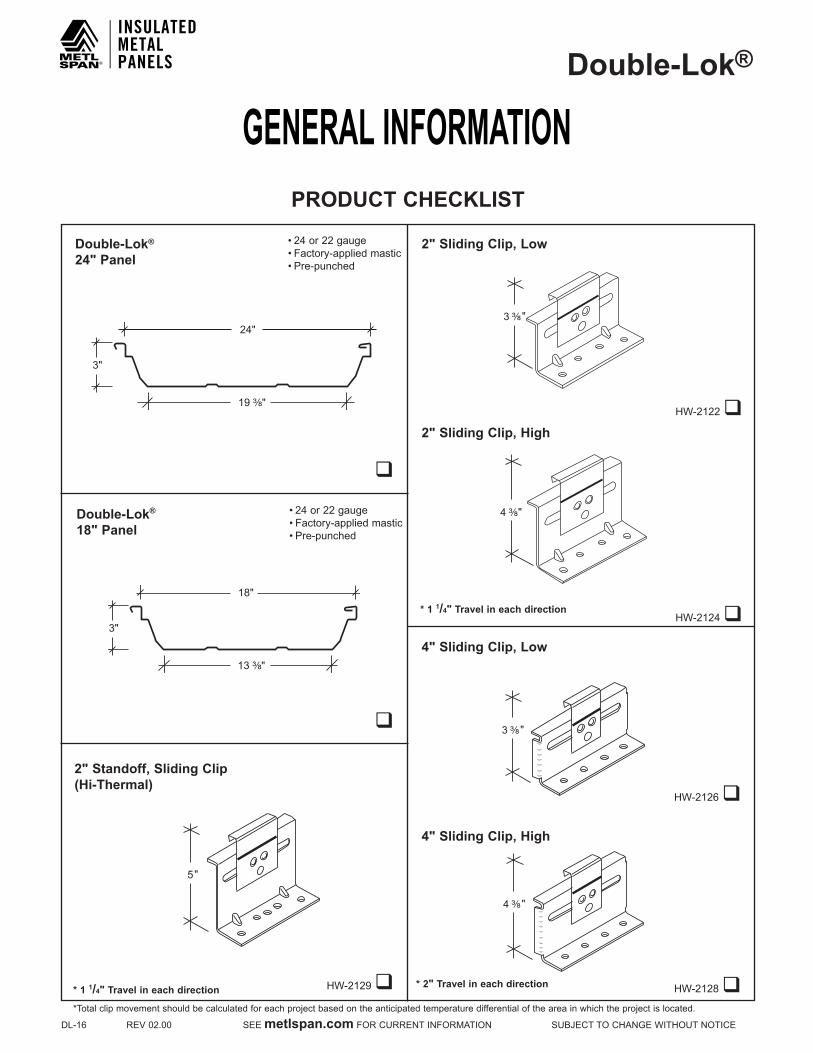
CoverageWidth-24"withminorribs-prepunched6holes 18"withminorribs-prepunched5holes
MinimumSlope-¼":12
PanelAttachment-Low,high(sliding)
PanelSubstrate-GalvalumePlus®(standard)
Gauge-Standard:24Optional:22
Finishes - Smooth or embossed with minor ribs
Coatings-Signature®200,Signature®300,Signature®300Metallic
GENERAL INFORMATION
PRODUCT SELECTION CHART
3"
19 ³⁄₈"
24" or 18"
Signature® is a registered trademark of the Cornerstone Bulding Brands family. Galvalume Plus® is a registered trademark of BIEC Internationall- Available in any quantity. q- Minimum quantity may be required.
Signature® 200 White only 24 Gauge is available in all widths, at any quantity. Other colors, finishes, gauges, and materials available; please inquire.
CAUTIONDiaphram capabilities and purlin stability are not provided by the Double-Lok® roof system. Therefore, other bracing may be requiredtoconformtoA.I.S.C.orA.I.S.I.specifications.
FINISH Signature®300 Signature®300 Metallic
Signature®200 Galvalume Plus®
PRODUCT 24Gauge 22Gauge 24Gauge 22Gauge 24Gauge 22Gauge 24Gauge 22GaugeDouble-Lok®
24"Wide q q q q q q l q
18"Wide l q q q l q l q
GENERAL INFORMATIONDouble-Lok®
DL-16REV02.00SEEmetlspan.comFORCURRENTINFORMATIONSUBJECTTOCHANGEWITHOUTNOTICE
PRODUCTCHECKLISTPRODUCT CHECkLIST
q
HW-2129q
•24or22gauge•Factory-applied mastic•Pre-punched
Double-Lok® 24" Panel
2" Sliding Clip, Low
2" Standoff, Sliding Clip(Hi-Thermal)
4" Sliding Clip, High
q
Double-Lok® 18" Panel
•24or22gauge•Factory-applied mastic•Pre-punched
24"
3"
19 ³⁄₈"
18"
3"
13 ³⁄₈"
5"
* 1 1/4" Travel in each direction
2" Sliding Clip, HighHW-2122q
HW-2124q
4" Sliding Clip, Low
HW-2126q
HW-2128q* 2" Travel in each direction
*Total clip movement should be calculated for each project based on the anticipated temperature differential of the area in which the project is located.
3 ³⁄₈ "
4 ³⁄₈ "
3 ³⁄₈ "
4 ³⁄₈"
* 1 1/4" Travel in each direction

GENERAL INFORMATIONDouble-Lok®
SUBJECTTOCHANGEWITHOUTNOTICESEEmetlspan.comFORCURRENTINFORMATIONREV02.00DL-17
HW-7618qHW-7617q
HW-7636qHW-7632q
1"
1 ¹⁄₂"
1 ¹⁄₂"
1 ¹⁄₂"
5 ⁷⁄₁₆"
1"³⁄₈"
1 ¹⁄₂"
4 ¹⁄₂"¹⁵⁄₁₆"
4 ¹⁄₁₆"
³⁄₈"
1 ⁷⁄₈"1"
4 ¹⁄₁₆"
1 ³⁄₈"
1 ³⁄₄"2 ¹⁄₈"
1¹⁄₂"
19⁄16"
³⁄₈"
15⁄16"
PRODUCTCHECKLISTPRODUCT CHECkLIST
HW-7616qHW-7600q
Eave Plate, Low(Optional)
Eave Plate, High
Floating Eave Plate, Low Floating Eave Plate, High
HW-7628q1"
³⁄₈" 6 ¹⁄₁₆"
1 ⁷⁄₈"
4" Floating Eave Plate, Low
Mid-Slope Fixed Plate, Low Mid-Slope Fixed Plate, High
• 8'-0"length• 14gaugepainted• Factory slots• For use with high clips
• 8'-0"length• 14gaugepainted• Factory slots• For use with high clips
• 20'-0"length• 14gaugepainted• Factory slots• For use with low clips
• 20'-0"length• 14gaugepainted• Factory slots• For use with high clips
• 8'-0"length• 14gaugepainted• Use at eave when
attaching panels to substructure at midpoint
• 8'-0"length• 14gaugepainted• Use at eave when
attaching panels to substructure at midpoint
• 6'-0"length• 14gaugepainted• Use at mid-point endlap
when attaching panels to substructure at midpoint
• 6'-0"length• 14gaugepainted• Use at mid-point endlap
when attaching panels to substructure at midpoint
• 8'-0"length• 14gaugepainted• Use at eave when
attaching panels to substructure at midpoint
• 8'-0"length• 14gaugepainted• Use at eave when
attaching panels to substructure at midpoint
HW-7629q
2³⁄₈"
1"
6¹⁄₁₆"1¹⁄₂"
4" Floating Eave Plate, High
Rake Support, High
HW-7720q
4 ³⁄₈"
1 ¹⁄₂"HW-7710q
Rake Support, Low
3 ³⁄₈"
2 ¹⁄₂ "*Total clip movement should be calculated for each project based on the anticipated temperature differential of the area in which the project is located.
GENERAL INFORMATIONDouble-Lok®
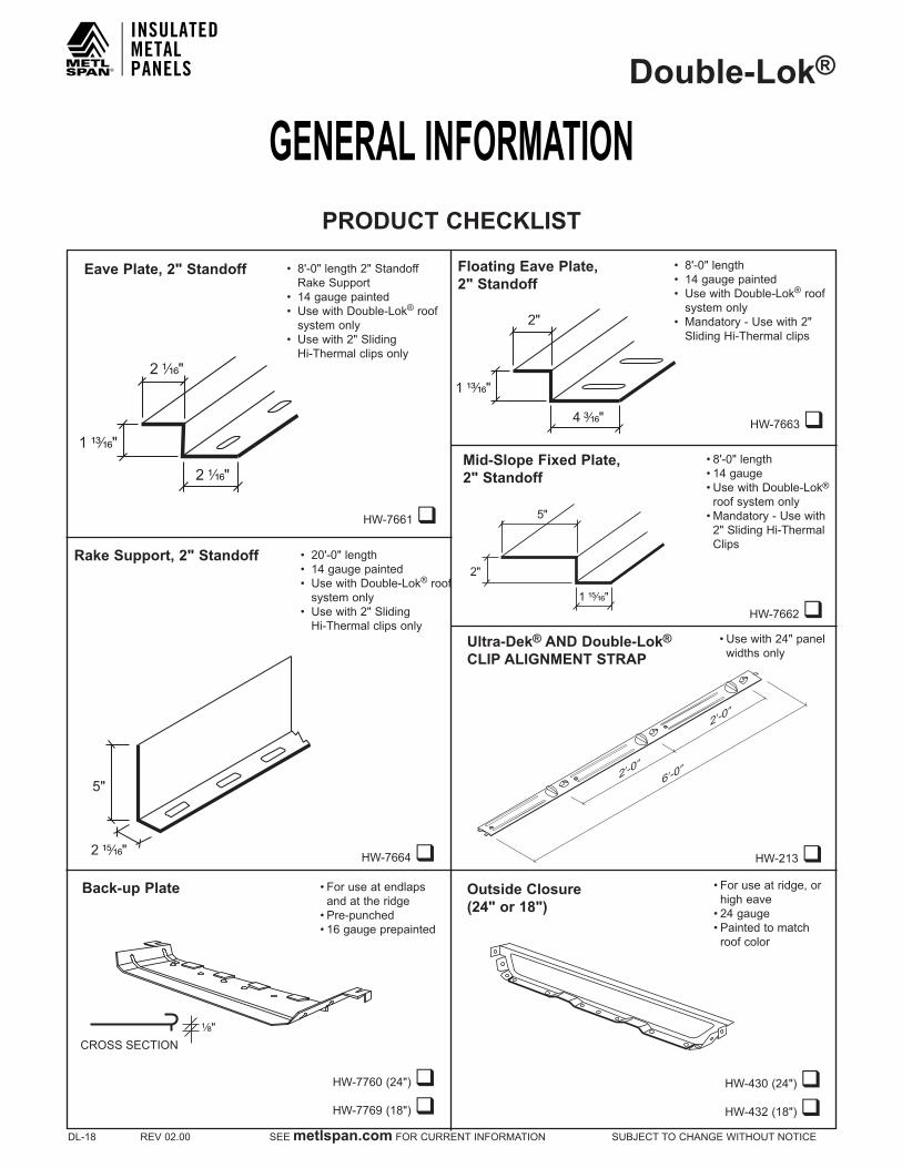
DL-18REV02.00SEEmetlspan.comFORCURRENTINFORMATIONSUBJECTTOCHANGEWITHOUTNOTICE
Outside Closure(24" or 18")
Ultra-Dek® AND Double-Lok®
CLIP ALIGNMENT STRAP
HW-213q
HW-430(24")qHW-432(18")q
• For use at ridge, or high eave•24gauge• Painted to match
roof color
•Usewith24"panelwidths only
6’-0”2’-0”
2’-0”
Floating Eave Plate, 2" Standoff
HW-7663q4 ³⁄₁₆"
1 ¹³⁄₁₆"
2"
PRODUCT CHECkLIST
HW-7661q
2 ¹⁄₁₆"
1 ¹³⁄₁₆"
2 ¹⁄₁₆"
Eave Plate, 2" Standoff
HW-7664q2 ¹⁵⁄₁₆"
5"
Rake Support, 2" Standoff
Back-up Plate • For use at endlaps and at the ridge •Pre-punched•16gaugeprepainted
¹⁄₈"CROSS SECTION
HW-7760(24")qHW-7769(18")q
Mid-Slope Fixed Plate,2" Standoff
HW-7662q
•8'-0"length•14gauge•UsewithDouble-Lok®
roof system only• Mandatory - Use with 2"SlidingHi-ThermalClips
1 ¹⁵⁄₁₆"
2"
5"
• 8'-0"length2"StandoffRake Support
• 14gaugepainted• UsewithDouble-Lok® roof
system only• Usewith2"Sliding
Hi-Thermal clips only
• 20'-0"length• 14gaugepainted• UsewithDouble-Lok® roof
system only• Usewith2"Sliding
Hi-Thermal clips only
• 8'-0"length• 14gaugepainted• UsewithDouble-Lok® roof
system only• Mandatory-Usewith2"
Sliding Hi-Thermal clips
GENERAL INFORMATIONDouble-Lok®
SUBJECTTOCHANGEWITHOUTNOTICESEEmetlspan.comFORCURRENTINFORMATIONREV02.00DL-19
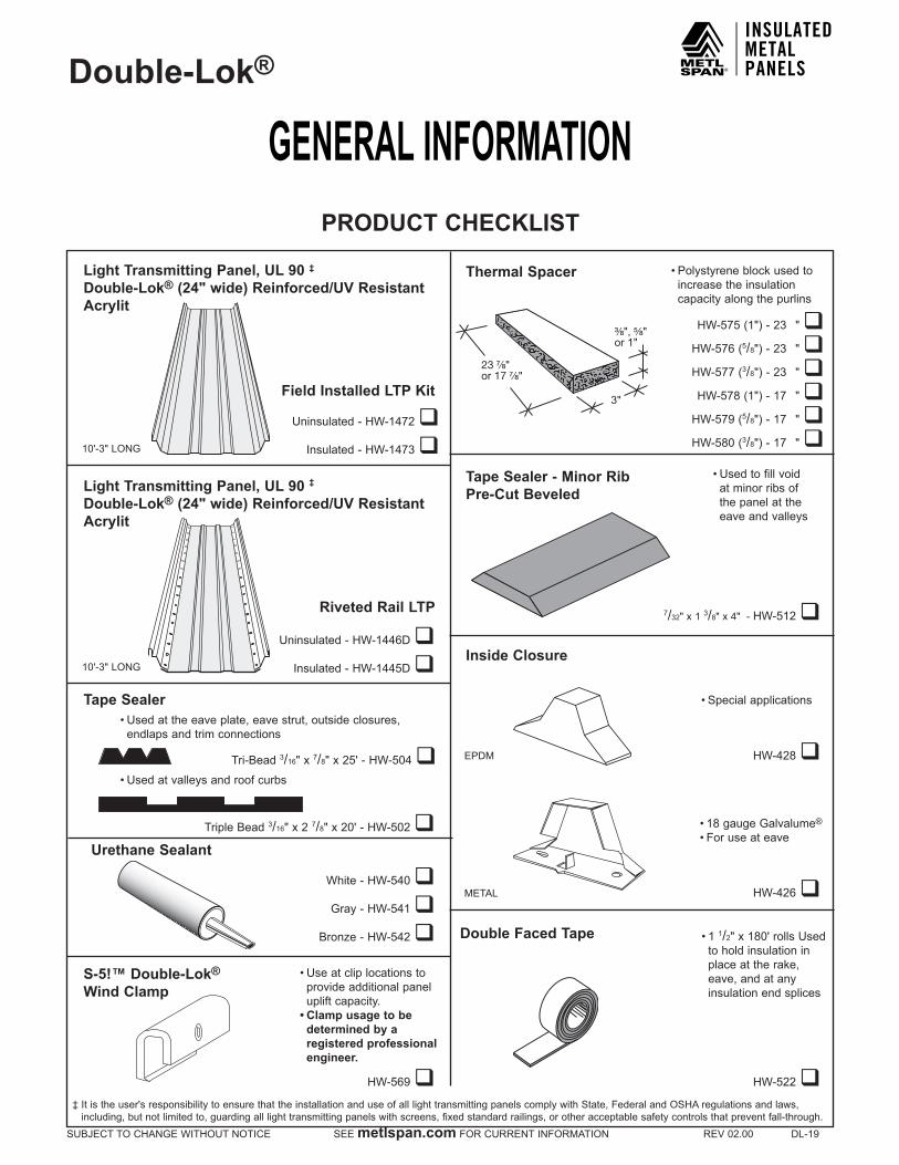
HW-569q
White-HW-540qGray-HW-541q
Bronze-HW-542q
• Used at the eave plate, eave strut, outside closures, endlaps and trim connections
Light Transmitting Panel, UL 90 ‡
Double-Lok® (24" wide) Reinforced/UV Resistant Acrylit
Thermal Spacer
S-5!™ Double-Lok® Wind Clamp
Inside Closure
Uninsulated-HW-1472qInsulated-HW-1473q
Light Transmitting Panel, UL 90 ‡
Double-Lok® (24" wide) Reinforced/UV Resistant Acrylit
Urethane Sealant
Tape Sealer - Minor RibPre-Cut Beveled
7/32"x13/8"x4"-HW-512q
HW-522q
• Use at clip locations to provide additional panel uplift capacity.• Clamp usage to be
determined by a registered professional engineer.
•Special applications
•Polystyrene block used to increase the insulation capacity along the purlins
• Used to fill void at minor ribs of the panel at the eave and valleys
Field Installed LTP kit
10'-3"LONG
10'-3"LONG
Uninsulated-HW-1446DqInsulated-HW-1445Dq
Riveted Rail LTP
• Used at valleys and roof curbs
Tape Sealer
TripleBead3/16"x27/8"x20'-HW-502q
Tri-Bead3/16"x7/8"x25'-HW-504q
HW-575(1")-23MMM"qHW-576(5/8")-23MMM"q
HW-577(3/8")-23MMM"qHW-578(1")-17MMM"qHW-579(5/8")-17MMM"q
HW-580(3/8")-17MMM"q
•18gaugeGalvalume®
•For use at eave
HW-428q
HW-426q
Double Faced Tape •11/2"x180'rollsUsedto hold insulation in place at the rake, eave, and at any insulation end splices
3"
³⁄₈", ⁵⁄₈"or 1"
23 ⁷⁄₈"or 17 ⁷⁄₈"
EPDM
METAL
PRODUCT CHECkLIST
‡Itistheuser'sresponsibilitytoensurethattheinstallationanduseofalllighttransmittingpanelscomplywithState,FederalandOSHAregulationsandlaws,including,butnotlimitedto,guardingalllighttransmittingpanelswithscreens,fixedstandardrailings,orotheracceptablesafetycontrolsthatpreventfall-through.
GENERAL INFORMATIONDouble-Lok®
DL-20REV02.00SEEmetlspan.comFORCURRENTINFORMATIONSUBJECTTOCHANGEWITHOUTNOTICE
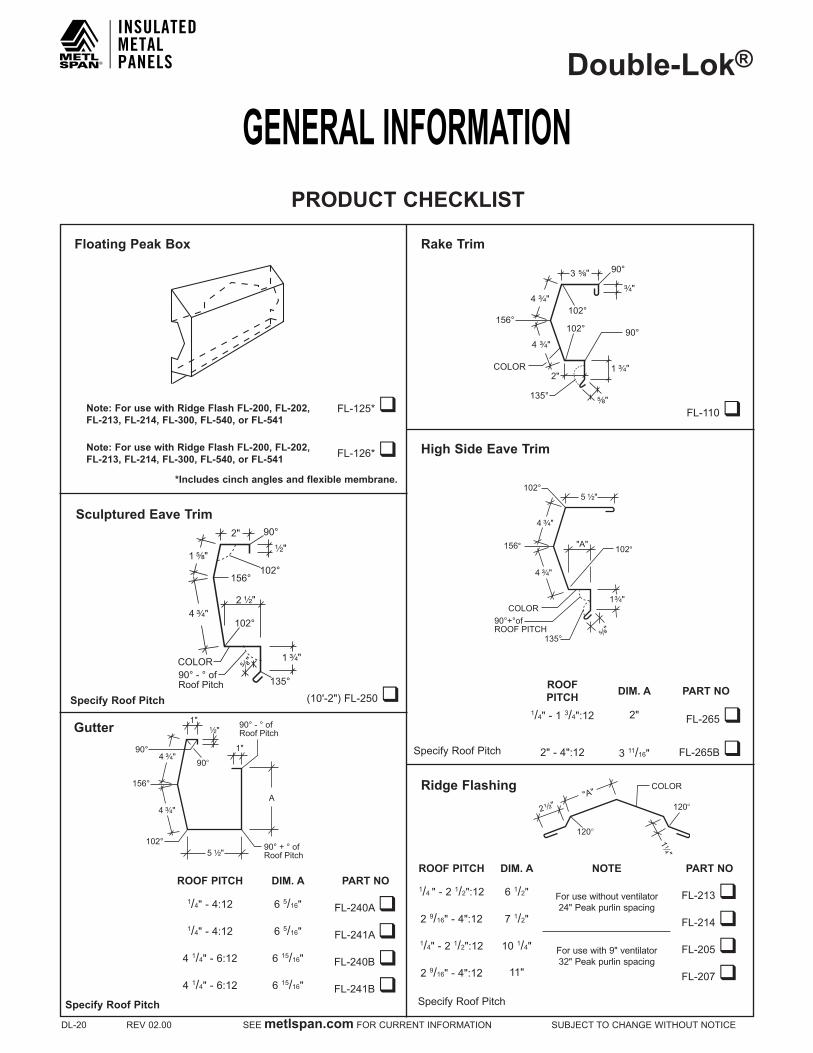
(10'-2")FL-250q
Floating Peak Box Rake Trim
Gutter
Ridge Flashing
FL-125*q
FL-126*q
Sculptured Eave Trim
High Side Eave Trim
FL-110q
Specify Roof Pitch
Specify Roof Pitch
*Includes cinch angles and flexible membrane.
Note: For use with Ridge Flash FL-200, FL-202,FL-213, FL-214, FL-300, FL-540, or FL-541
Note: For use with Ridge Flash FL-200, FL-202,FL-213, FL-214, FL-300, FL-540, or FL-541
ROOF PITCH DIM. A PART NO
1/4"-4:12 65/16" FL-240Aq1/4"-4:12 65/16" FL-241Aq41/4"-6:12 615/16" FL-240Bq41/4"-6:12 615/16" FL-241Bq
ROOF PITCH DIM. A PART NO
1/4"-13/4":12 2" FL-265q
2"-4":12 311/16" FL-265Bq
ROOF PITCH DIM. A NOTE PART NO
1/4"-21/2":12 61/2" For use without ventilator 24"Peakpurlinspacing
FL-213q29/16"-4":12 71/2" FL-214q1/4"-21/2":12 101/4" Forusewith9"ventilator
32"PeakpurlinspacingFL-205q
29/16"-4":12 11" FL-207qSpecify Roof Pitch
90° 1"
1"
156°
102°
90° - ° ofRoof Pitch
90° + ° ofRoof Pitch
¹⁄₂"
4 ³⁄₄"
4 ³⁄₄"
5 ¹⁄₂"
90°
A
5 ¹⁄₂"
"A"
COLOR
156°
135°
102°
90°+°ofROOF PITCH
102°
4 ³⁄₄"
4 ³⁄₄"
⁵⁄₈"
1³⁄₄"
2"COLOR
156°
135°
90°
90°
102°
102°
³⁄₄"4 ³⁄₄"
⁵⁄₈"
3 ⁵⁄₈"
4 ³⁄₄"
1 ³⁄₄"
2 ¹⁄₂"
"A"
1¹⁄₄"
120°
120°
COLOR
2"
COLOR
1 ⁵⁄₈"¹⁄₂"
4 ³⁄₄"
1 ³⁄₄"
2 ¹⁄₂"
⁵⁄₈"
90°
102°
102°
90° - ° of Roof Pitch 135°
156°
PRODUCT CHECkLIST
Specify Roof Pitch

GENERAL INFORMATIONDouble-Lok®
SUBJECTTOCHANGEWITHOUTNOTICESEEmetlspan.comFORCURRENTINFORMATIONREV02.00DL-21
FL-132q
FL-265q
FL-110q
Gutter Strap
Mitered Sculptured High Side Eave (Right or Left)
FL-246q
Sculptured Eave Corner Box
Mitered Sculptured Rake(Left or Right)
PRODUCT CHECkLIST
FL-115q
FL-240q
FL-568q
Ridge End Cap
Mitered Sculptured Gutter(Right or Left)
FL-204q
Rake Slide
Light Transmitting Panel Trim
FL-117q
FL-271q
FL-272q
Perforated Vent Drip
Offset Panel Cap Trim
FL-254q
Variable Termination
Box Panel Cap Trim
10"
LEFT RIGHT
LEFT RIGHT
1 ³⁄₈"
¹⁄₂"
1 ¹⁄₈"95
2" SPECIFY ANGLE
2 ¹⁄₂"
1"
¹⁄₂"
1"
3 ¹⁄₄"
1"
PERFORATED
³⁄₄"
90 °1"
45 °
¹⁄₂" COLOR
"A"
³⁄₄"
9"
90
COLOR
LEFT RIGHT
¹⁄₂"
4"
¹⁄₂"
SPECIFYANGLE
3 ¹⁄₄"
2 ¹⁄₄"
COLOR
90
Specify Roof Pitch Specify Roof Pitch Specify Roof Pitch
Specify Roof Pitch

GENERAL INFORMATIONDouble-Lok®
DL-22REV02.00SEEmetlspan.comFORCURRENTINFORMATIONSUBJECTTOCHANGEWITHOUTNOTICE
FL-285(3")qFL-286(5")qFL-287(7")q
P-141q
Parapet Rake Flash
Hip Support Plate
PRODUCT CHECkLIST
FL-341q
Counter Flash
FL-343q
FL-274(41/2")qFL-275(31/2")q
Alternate Counter Flash
Parapet High Side Eave Flash
24 Gauge Material 24 Gauge Material
1"
150° COLOR
¹⁄₂"
⁵⁄₈"
³⁄₄"
⁵⁄₈"
30°
1"90° COLOR
2 ¹⁄₂"
¹⁄₂"
Extended Valley — All Systems
FL-708q
21"
SPECIFY ANGLE
45°
3"
4 ³⁄₄"
SPECIFY ANGLE
3 ¹⁄₂" or 4 ¹⁄₂"
2 ¹⁄₂"1 ¹⁄₄"
10 ¹¹⁄₁₆"
1"SPECIFY ANGLE
1"
10 ¹¹⁄₁₆"
4"
3", 5" or 7"
1"
OPEN HEM
Standard Valley — All Systems
FL-700q
3"
16"
45°
SPECIFY ANGLE
P-111q
Valley Support Plate — Low Systems
23"
SPECIFY ANGLE
901” °
•ExtendedValleysP-162q
Valley Support Plate — High Systems
21"SPECIFY ANGLE
135°
1 ⁷⁄₁₆"
1 ⁹⁄₁₆"
135°
1"
P-101q
Valley Support Plate — Low Systems
90°
SPECIFY ANGLE
17"1"
17"1”
P-163q
Valley Support Plate — 2" Standoff Systems
2 ⁵⁄₁₆"1 ⁵⁄₈"
20"SPECIFY ANGLE
135°
1 ⁹⁄₁₆"
135°
FL-290q
Parapet Rake Cleat1"
³⁄₄"
¹⁄₂"
COLOR
•StandardandExtendedValleys
•StandardValleys •StandardandExtendedValleys

GENERAL INFORMATIONDouble-Lok®
SUBJECTTOCHANGEWITHOUTNOTICESEEmetlspan.comFORCURRENTINFORMATIONREV02.00DL-23
q
q
q
Fastener #1
Fastener #6
q
Fastener #1F
Fastener #4
PRODUCT CHECkLIST
q
q
Fastener #1E
q
Fastener #2A
Fastener #5
1/4"-14 x 1" Self Driller5/16" Hex Washer Head with 5/8" O. D. washer
1/4"-14 x 1 1/2" Self Driller5/16" Hex Washer Head with 5/8" O.D. washer
1/4"-14 x 7/8" Lap Tek® Long Life Self Driller5/16" Hex Washer Head with sealing washer(Long life exterior fastener)
12-24 x 11/4" TEk® 4.5 Self Driller5/16" Hex Washer Head with5/8" O.D. washer
17 x 1" Type AB Long Life5/16" Hex Washer Head with sealing washer(Long life exterior fastener)
1/4"-14 x 1 1/4" Shoulder Tek® 2 Self Driller5/16" Hex Washer Head, no washer
1/4"-14 x 1 1/4" Long Life Self Driller5/16" Hex Washer Head with sealing washer(Long life exterior fastener)
•Cliptopurlinwithupto4"insulationthickness•Eaveplatetoeave
strut•Inside closure to eave
plate or eave strut•Rake support to purlin (FixedSystemOnly)
•Cliptopurlinwithover4"insulationthickness
•Ridge and other flashing to outside closure•Guttertopanel•Guttertostrap•Trim to trim connections
•Cliptojoist•Eaveplatetobeam•Rake support to joist•(FixedSystemOnly)
• Panel to eave plate or eave strut•Rake trim to roof panel•Outside closure•Endlap
•Use in place of Fasteners#1Eand#4at all stripouts
•Rake support to purlin (FloatingSystemOnly)•Floating eave plate to
eave strut
Fastener #8
q10 x 1 1/2" Woodgrip1/4" Hex Washer Head with1/2" O.D. washer
•Special application fastener•Foruseon2x4lathand
other solid wood deck (Notforuseinplywood)

GENERAL INFORMATIONDouble-Lok®
DL-24REV02.00SEEmetlspan.comFORCURRENTINFORMATIONSUBJECTTOCHANGEWITHOUTNOTICE
q
q
qFastener #14A
Fastener #10
Fastener #12A
PRODUCT CHECkLIST
q
q
q
Fastener #9
Fastener #46
q
Fastener #11
Fastener #14
1/4"-14 x 1" Type B3/8" Hex Washer Head with5/8" O.D. washer
12 x 1" Pancake Head Self Driller#2 Quadrex Drive
1/8" x 3/8" Stainless Steel Pop Rivet
1/4"-14 x 5/8" Long Life Type B5/16" Hex Washer Head with Sealing Washer
1/4" x 1 1/4" Nail DriveMasonry Anchor
1/8" x 3/16" Stainless Steel Pop Rivet
10 x 1 1/2" Long Life Woodgrip5/16" Hex Washer Head with sealing washer(Long life exterior fastener)
•Special application fastener•For use on structural steel
up to 1/2"thick•Requires pre-drilled hole
•Support plate to purlins at valley and hip conditions•Rake angle to purlins
•Snow gutter to eave plate•Outside closure to back-
up angle at hip condition
•Special application fastener•Foruseon2x4lathand
other solid wood deck (Notforuseinplywood)
•Special application fastener•For use on masonry
•Gutterstraptosnowgutter
•Special Application Fastener•Endlapoversoliddeck
or rigid insulation
q
Fastener #226
q
Fastener #228
3/16" x 9/16" Aluminum Closed End Rivet 10 x 1/2" Aluminum Washer
•Dekstriptoexpansionridge/expansionlap
•Dekstriptoexpansionridge/expansionlap•Used with Fastener #226
q
Fastener #43L
1/4"-14 x 1 1/4" Long Life Self Driller5/16" Hex Washer Head with 1 1/8" O.D. Washer
•Use at down slope end lapofLTPS

GENERAL INFORMATIONDouble-Lok®
SUBJECTTOCHANGEWITHOUTNOTICESEEmetlspan.comFORCURRENTINFORMATIONREV02.00DL-25
NOTEIt is the responsibility of the erector to install this roof using safe construction practices that are in compliance with OSHA regulations. Metl-Span is not responsible for the performance of this roof system if it is not installed in accordance with the instructions shown in this manual. Deviations from these instructions and details must be approved in writing by Metl-Span.
PREPARATORY REQUIREMENTS1.AsinglepitcheavestrutmustbeusedwiththeDouble-Lok® roof system.
2.Makesurearakeangleoranalternatestructuralflatsurfacehasbeeninstalledontopofthepurlinstoacceptthe“RakeSupport”.
3.Thewallsdonothavetobeerectedbeforetheroofisinstalled.However,forthepurposeofthismanual,wehaveassumedthat the wall panels have been installed.
4.Allprimaryandsecondaryframingmustbeerected,plumbedandsquaredwithboltstightenedaccordingtoacceptedbuildingpractices.
5.Thesubstructure(eavetoridge)mustbeonplane(1/4"in20'or3/8"in40'tolerance).
6. Double-Lok® can be erected on various types of construction. However, for the purpose of this manual, we have assumed that the roof will be installed on a new, pre-engineered metal building.
7. Double-Lok®roofpanelscanbefurnishedin24",or18"widths.However,forthepurposeofthismanual,wehaveassumedthattheroofpanelswillbe24"wide.
8.Itiscriticalthatthepurlinsorjoistsattheridgeandendlapsbeexactlylocatedasdetailedandthattheyarestraightfromrafter to rafter. Any mislocation or bowing of these members can cause the fasteners at the endlaps or outside closures to foulasthepanelsexpandandcontract.Oilcanningisnotacauseforrejection.
9.Peakpurlinspacing-24"(12"fromthecenterlineofthebuilding).
10.If your roof is to be UL 90 rated, see special UL 90 requirements on page DL-4.
11.ReadrecommendederectionpracticesonpagesDL-53–DL-55beforeproceedingwithroofinstallation.
12.Metl-Span recommends the use of a screw gun with a speed range of 0 - 2000 RPM to properly install all fasteners referenced in this manual. Tools rated to 4000 RPM should never be used for self drilling fasteners typically supplied with metal building components.
13.Fieldcuttingofthepanelsshouldbeavoidedwherepossible.Iffieldcuttingisrequired,thepanelsmustbecutwithnibblers,snips, or shears to prevent edge rusting. Do not cut the panels with saws, abrasive blades, grinders, or torches.
CAUTIONDiaphragmcapabilitiesandpurlinstabilityarenotprovidedbyMetl-Span’sDouble-Lok® roof system. Therefore, other bracing may be required.
CAUTIONThe minimum recommended slope for the roof system is 1/4on12.Aslopeoflessthan1/4on12couldcauseseverepondingand will void material warranties.
CAUTIONApplication and design details are for illustration purposes only, and may not be appropriate for all environmental conditions or building designs. Projects should be engineered to conform to applicable building codes, regulations, and accepted industry practices.
WARNING: Light transmitting panels are not designed or intended to bear the weight of any person walking, stepping, standing or resting on them. Metl-Span DISCLAIMS ANY WARRANTY OR REPRESENTATION, EXPRESS OR IMPLIED, that any person can safely walk, step, stand or rest on or near these light transmitting panels or that they comply with any OSHA regulation.
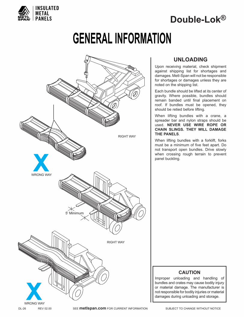
GENERAL INFORMATIONDouble-Lok®
DL-26REV02.00SEEmetlspan.comFORCURRENTINFORMATIONSUBJECTTOCHANGEWITHOUTNOTICE
CAUTIONImproper unloading and handling of bundles and crates may cause bodily injury or material damage. The manufacturer is not responsible for bodily injuries or material damages during unloading and storage.
UNLOADING Upon receiving material, check shipment against shipping list for shortages and damages. Metl-Span will not be responsible for shortages or damages unless they are noted on the shipping list.
Eachbundleshouldbeliftedatitscenterofgravity. Where possible, bundles shouldremain banded until final placement on roof. If bundles must be opened, they should be retied before lifting.
When lifting bundles with a crane, aspreader bar and nylon straps should be used. NEVER USE WIRE ROPE OR CHAIN SLINGS. THEY WILL DAMAGE THE PANELS.
When lifting bundles with a forklift, forksmust be a minimum of five feet apart. Do not transport open bundles. Drive slowly when crossing rough terrain to prevent panel buckling.
RIGHT WAY
WRONG WAYX
5' Minimum
RIGHT WAY
WRONG WAYX

GENERAL INFORMATIONDouble-Lok®
SUBJECTTOCHANGEWITHOUTNOTICESEEmetlspan.comFORCURRENTINFORMATIONREV02.00DL-27
NOTEProtective gloves should always be used while handling panels. OSHA safety regulations must be followed at all times.
1 0 ' t o 1 2 '
1 0 ' t o 1 2 '
5 '
RIGHT WAY
WRONG WAY
HANDLING/ PANEL STORAGE
Standing on one side of the panel, lift it by theseam.Ifthepanelisover10'long,liftitwith two or more people on one side of the panel to prevent buckling.
Do not pick panels up by the ends.
Store bundled sheets off the ground sufficiently high to allow air circulation beneath bundle and to prevent rising water from entering bundle. Slightly elevate one end of bundle. Prevent rain from entering bundle by covering with tarpaulin, making provision for air circulation between draped edges of tarpaulin and the ground. PROLONGED STORAGE OF SHEETS IN A BUNDLE IS NOT RECOMMENDED. If conditions do not permit immediate erection, extra care should be taken toprotect sheets from white rust or water marks.
Checktoseethatmoisturehasnotformedinside the bundles during shipment. If moisture is present, panels should be uncrated and wiped dry, then restacked and loosely covered so that air can circulate between the panels.
BAND ONLYThis method is used on all orders, unless otherwise specified by customer. The panels are banded together, causing them to curl up. This enhances the strength of the bundles. Panels bundled in this manner may be handled by a forklift in lengths to 30'. The forklift should have at least 5'between forks. Lengths in excess of 30'must be lifted utilizing a spreader bar. Special care must be given during handling to avoid damage to the locking edges of the panels.
GENERAL INFORMATIONDouble-Lok®
DL-28REV02.00SEEmetlspan.comFORCURRENTINFORMATIONSUBJECTTOCHANGEWITHOUTNOTICE
PROPER HANDLING, STORAGE AND MAINTENANCE OF PAINTEDAND GALVALUME PLUS® PANELS
PANEL HANDLING•Allpanelbundlesmustbeinspectedduringunloadingandcarriermustbeadvisedimmediatelyifdamageisnoted.
•Neverunloadormovepanelbundlesthathavebeenopenedwithoutadequatelyclampingthem.Withoutthebandingtohold the bundle stable, panels may shift during unloading or movement, causing the bundle to fall.
•Neverusewireslingstounloadormovepanelbundles.
•Whenunloadingormovingpanelbundlesover20'long,aspreaderbarmayberequired.Itistheerector'sresponsibilityto determine the location and number of lift points required to safely unload or move panel bundles.
•Whenhandlingindividualpanels,alwayswearprotectivegloves.OSHAsafetyregulationsmustbefollowedatalltimes.
•Whencuttingpanels,alwayswearallrequiredsafetyequipmentincluding,butnotlimitedto,safetyglassesandgloves.Cutpanelswithnibblers, shearsor snips.Donotuseabrasivebladesawsas thesewillmelt theGalvalume® coating causingthepaneltoedgerustwhichwillvoidtheGalvalume® and paint warranties. Drilling fasteners into panels will create metal filings that will rust and create an unsightly stain. Metal filings must be removed by sweeping or wiping down panels immediately after installation to avoid this occurrence.
PANEL STORAGE•Ifwaterispermittedtoenterpanelbundles,itisnecessarytoopenbundles,separatethepanelsanddryallsurfaces.
•Storebundledpanelsoffthegroundsufficientlyhightoallowaircirculationbeneathbundleandtopreventrisingwaterfromentering bundle. Slightly elevate one end of bundle.
•Preventrainfromenteringbundlebycoveringwithtarpaulin,makingprovisionforaircirculationbetweendrapededgesoftarpaulin and the ground.
•Prolongedstorageofpanelsinabundleisnotrecommended.Ifconditionsdonotpermitimmediateerection,extracareshould be taken to protect panels from white rust or water marks. If panels have not been erected within three weeks of receipt,thepanelsshouldberemovedfromthebundleforinspection.Condensationmaycausedamagetopanels.Themanufacturer'spaintandGalvalume® warranties do not cover damage caused by improper panel storage.

GENERAL INFORMATIONDouble-Lok®
SUBJECTTOCHANGEWITHOUTNOTICESEEmetlspan.comFORCURRENTINFORMATIONREV02.00DL-29
NOTICEUniformvisualappearanceofGalvalumePlus® coatedpanelscannotbeguaranteed.TheGalvalumePlus® coating is subject to variances in spangle from coil to coil which may result in a noticeable shade variation in installed panels. The GalvalumePlus® coating is also subject to differential weathering after panel installation. Panels may appear to be different shades due to this weathering characteristic. If uniform visual appearance is required, the manufacturer recommends that our prepainted Signature®200orSignature®300panelsbeusedinlieuofGalvalumePlus®. Shade variations in panels manufacturedfromGalvalumePlus® coated material do not diminish the structural integrity of the product. These shade variations should be anticipated and are not a cause for rejection.
PROPER HANDLING, STORAGE AND MAINTENANCE OF PAINTEDAND GALVALUME PLUS® PANELS
(CONTINUED)
PANEL MAINTENANCE•NeverallowGalvalume® panels to come into contact with or water runoff from dissimilar materials such as copper, lead, or graphite.ThesematerialswillcausegalvaniccorrosionofthepanelsandwillvoidtheGalvalume® warranty. This includes treatedwoodandACcondensate,bothofwhichcontaincoppercompounds.Thisalsoappliestopaintedpanels.
•Alwaysuselonglifefastenersinallexposedfastenerapplications.Nonlonglifefastenerscanrustthroughthepanelateachexposedfastenerlocation.UseofnonlonglifefastenersinexposedapplicationswillvoidtheGalvalume® and paint warranties.
•Panelsshouldbeprotectedagainstexposuretomasonryproducts,strongacidsorbasesandsolvents.ExposuretotheseagentsmayetchorstainGalvalumePlus® panels and cause painted panels to blister or peel.
•Neverallowanyonetoapplyanycoatingorpatchingmaterialtothepanelsurface.Theseproductsmaycontainchemicalsthatwill adversely affect theGalvalumePlus® or paint coating. Also, water may become trapped between the coating material and the panel, causing premature corrosion.
If you have any question as to proper methods to use in the handling, storage or maintenance of these panels, call your nearest manufacturer representative.
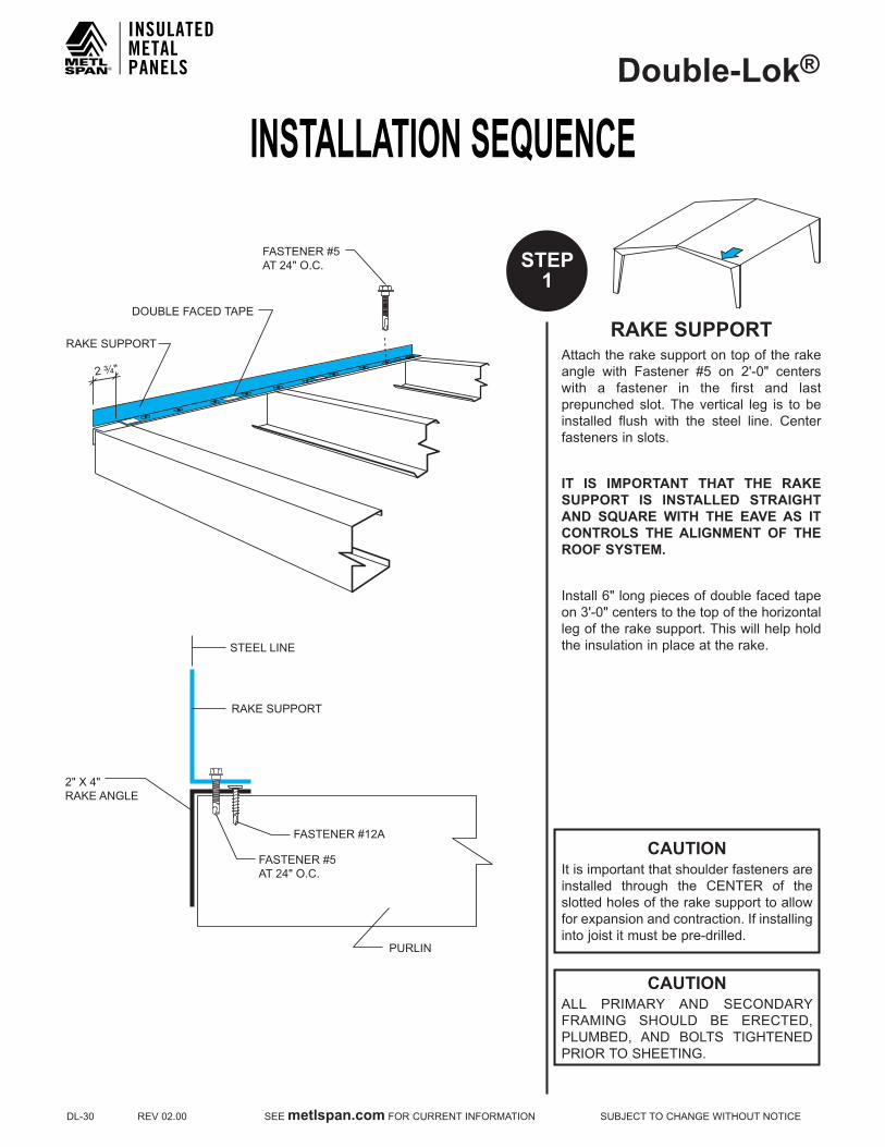
INSTALLATION SEQUENCEDouble-Lok®
DL-30REV02.00SEEmetlspan.comFORCURRENTINFORMATIONSUBJECTTOCHANGEWITHOUTNOTICE
CAUTIONIt is important that shoulder fasteners are installed through the CENTER of theslotted holes of the rake support to allow forexpansionandcontraction.Ifinstallinginto joist it must be pre-drilled.
RAkE SUPPORTAttach the rake support on top of the rake angle with Fastener #5 on 2'-0" centerswith a fastener in the first and last prepunched slot. The vertical leg is to be installed flush with the steel line. Centerfasteners in slots.
IT IS IMPORTANT THAT THE RAkE SUPPORT IS INSTALLED STRAIGHT AND SQUARE WITH THE EAVE AS IT CONTROLS THE ALIGNMENT OF THE ROOF SYSTEM.
Install6"longpiecesofdoublefacedtapeon3'-0"centerstothetopofthehorizontalleg of the rake support. This will help hold the insulation in place at the rake.
CAUTIONALL PRIMARY AND SECONDARYFRAMING SHOULD BE ERECTED,PLUMBED, AND BOLTS TIGHTENEDPRIORTOSHEETING.
STEEL LINE
PURLIN
2" X 4"RAKE ANGLE
RAKE SUPPORT
FASTENER #12A
DOUBLE FACED TAPE
RAKE SUPPORT
2 ³⁄₄"
FASTENER #5 AT 24" O.C.
FASTENER #5AT 24" O.C.
STEP1

INSTALLATION SEQUENCEDouble-Lok®
SUBJECTTOCHANGEWITHOUTNOTICESEEmetlspan.comFORCURRENTINFORMATIONREV02.00DL-31
STEP2
TRI-BEADTAPE SEALER
EAVE STRUT
OFFSET PANELCAP TRIM
TRI-BEADTAPE SEALER
EAVE STRUT
BOX PANELCAP TRIM
WALL PANEL
DOUBLE FACED TAPE
FASTENER #14
DOUBLE FACED TAPE
FASTENER #14
WALL PANEL INSTALLED BEFORE ROOF
WALL PANEL INSTALLED BEFORE OR AFTER ROOF
OFFSETPANEL CAPTRIM
2" LAP
BOX PANELCAP TRIM
URETHANESEALANT
URETHANESEALANT
2" LAP
1"
OFFSET PANEL CAPTRIM ENDLAP DETAIL
BOX PANEL CAP TRIM ENDLAP DETAIL
1"
LOW SYSTEM EAVEFor applications in which the wall panels have already been erected, install boxpanel cap trim to the eave strut with Fastener#14.Trimmustbepulledtight towall panels before fastening to eave strut. Use two fasteners per 10' piece or threefastenersper20'piece.Forapplicationsinwhich the wall panels have not been erected, use offset panel cap trim.
Lay Tri-Bead tape sealer on top of thepanelcaptrim(boxoroffset).
Install double faced tape along the length of the top leg of the panel cap trim (box oroffset).DoublefacedtapemustbeupslopefromTri-Beadtapesealer.
Lapboxoroffsetpanelcap trim2".Applytwo beads of urethane sealant between the trimpieces,approximately1"fromtheendof the bottom piece.

INSTALLATION SEQUENCEDouble-Lok®
DL-32REV02.00SEEmetlspan.comFORCURRENTINFORMATIONSUBJECTTOCHANGEWITHOUTNOTICE
LOW SYSTEM EAVE/METAL INSIDE CLOSUREUsingFastener#1,attachthefirstinsideclosure to the eave strut, locating the face of the inside closure with the steel line. NOTE THAT THE FIRST INSIDE CLOSURE MUST BE FIELD CUT IN HALF TO FILL THE VOID UNDER THE PARTIAL RIB.
Locateadditionalclosureson24"centersfrom the first closure to maintain panel module, attaching each with Fastener #1. Install two fasteners per closure.The first fastener should be installed through the slotted hole to allow for any adjustment that may be required. Place Tri-Beadtapesealeronthetopandsideof each closure to complete the seal at the eave. These may be pre-taped before installation. To maintain panel module, metal inside closures must be installed on 24" centers. Measure from tab to tab located on the metal inside closure.
Roll out insulation from eave to peak, laying the side of the insulation on top of the rake support. The first roll should be 3' wide. This will keep insulationsidelaps 1' from panel sidelaps. Allowapproximately 4" of insulation to hangpast thedouble faced tape (downslope)before sticking the insulation to the double faced tape.Cut and remove thefiberglass approximately 4" and fold thevapor barrier back over the insulation (upslope).
STEP2A
24" ONCENTER
BOX PANELCAP TIRM
CUT FIBERGLASSFROM VAPOR BARRIERAND FOLD VAPORBARRIER OVER
DOUBLE FACED TAPE
TRI-BEADTAPE SEALER
TRI-BEADTAPE SEALER
EAVE STRUT
BOX PANELCAP TRIM
WALL PANEL
DOUBLE FACED TAPE
FASTENER #14
FASTENER #1METAL INSIDECLOSURE
CAUTIONThe fiberglass insulation must not interfere with the Tri-Bead tape sealerwhich provides a positive seal at the eave.
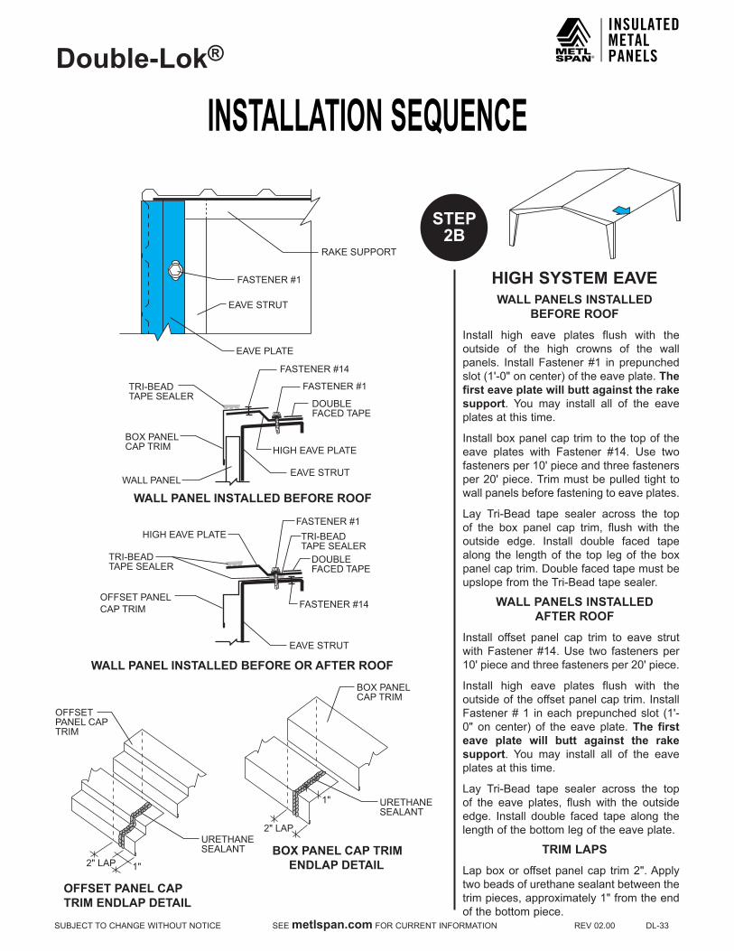
INSTALLATION SEQUENCEDouble-Lok®
SUBJECTTOCHANGEWITHOUTNOTICESEEmetlspan.comFORCURRENTINFORMATIONREV02.00DL-33
STEP2B
RAKE SUPPORT
FASTENER #1
EAVE PLATE
EAVE STRUT
TRI-BEADTAPE SEALER
TRI-BEADTAPE SEALER
EAVE STRUT
FASTENER #1
DOUBLEFACED TAPE
OFFSET PANELCAP TRIM FASTENER #14
HIGH EAVE PLATE
TRI-BEADTAPE SEALER
EAVE STRUT
FASTENER #1
FASTENER #14
WALL PANEL
DOUBLEFACED TAPE
BOX PANELCAP TRIM HIGH EAVE PLATE
OFFSETPANEL CAPTRIM
OFFSET PANEL CAPTRIM ENDLAP DETAIL
WALL PANEL INSTALLED BEFORE OR AFTER ROOF
WALL PANEL INSTALLED BEFORE ROOF
BOX PANEL CAP TRIM ENDLAP DETAIL2" LAP
BOX PANELCAP TRIM
URETHANESEALANT
URETHANESEALANT
2" LAP
1"
1"
HIGH SYSTEM EAVEWALL PANELS INSTALLED
BEFORE ROOF
Install high eave plates flush with the outside of the high crowns of the wall panels. InstallFastener#1 inprepunchedslot(1'-0"oncenter)oftheeaveplate.The first eave plate will butt against the rake support. You may install all of the eaveplates at this time.
Installboxpanelcaptrimtothetopoftheeave plates with Fastener #14. Use twofastenersper10'pieceandthreefastenersper20'piece.Trimmustbepulledtight towall panels before fastening to eave plates.
Lay Tri-Bead tape sealer across the topof the box panel cap trim, flush with theoutside edge. Install double faced tape along the lengthof the top legof theboxpanel cap trim. Double faced tape must be upslopefromtheTri-Beadtapesealer.
WALL PANELS INSTALLED AFTER ROOF
Install offset panel cap trim to eave strut withFastener#14.Use two fastenersper10'pieceandthreefastenersper20'piece.
Install high eave plates flush with the outside of the offset panel cap trim. Install Fastener#1 ineachprepunchedslot (1'-0" on center) of the eaveplate.The first eave plate will butt against the rake support. You may install all of the eaveplates at this time.
Lay Tri-Bead tape sealer across the topof the eave plates, flush with the outside edge. Install double faced tape along the length of the bottom leg of the eave plate.
TRIM LAPS
Lapboxoroffsetpanelcap trim2".Applytwo beads of urethane sealant between the trimpieces,approximately1"fromtheendof the bottom piece.
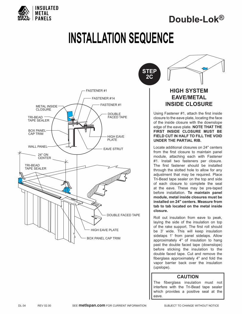
INSTALLATION SEQUENCEDouble-Lok®
DL-34REV02.00SEEmetlspan.comFORCURRENTINFORMATIONSUBJECTTOCHANGEWITHOUTNOTICE
STEP2C
CAUTIONThe fiberglass insulation must not interfere with the Tri-Bead tape sealerwhich provides a positive seal at the eave.
HIGH SYSTEM EAVE/METAL
INSIDE CLOSUREUsingFastener#1,attachthefirstinsideclosure to the eave plate, locating the face of the inside closure with the downslope edge of the eave plate. NOTE THAT THE FIRST INSIDE CLOSURE MUST BE FIELD CUT IN HALF TO FILL THE VOID UNDER THE PARTIAL RIB.
Locateadditionalclosureson24"centersfrom the first closure to maintain panel module, attaching each with Fastener #1. Install two fasteners per closure.The first fastener should be installed through the slotted hole to allow for any adjustment that may be required. Place Tri-Beadtapesealeronthetopandsideof each closure to complete the seal at the eave. These may be pre-taped before installation. To maintain panel module, metal inside closures must be installed on 24" centers. Measure from tab to tab located on the metal inside closure.
Roll out insulation from eave to peak, laying the side of the insulation on top of the rake support. The first roll should be 3' wide. This will keep insulationsidelaps 1' from panel sidelaps. Allowapproximately 4" of insulation to hangpast the double faced tape (downslope)before sticking the insulation to the double faced tape.Cut and remove thefiberglass approximately 4" and fold thevapor barrier back over the insulation (upslope).
TRI-BEADTAPE SEALER
24" ONCENTER
DOUBLE FACED TAPE
BOX PANEL CAP TRIM
TRI-BEADTAPE SEALER
EAVE STRUT
FASTENER #1
FASTENER #14
WALL PANEL
DOUBLEFACED TAPE
BOX PANELCAP TRIM
HIGH EAVEPLATE
HIGH EAVE PLATE
FASTENER #1
METAL INSIDECLOSURE
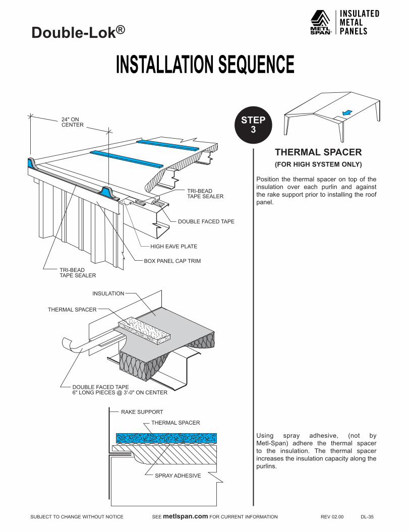
INSTALLATION SEQUENCEDouble-Lok®
SUBJECTTOCHANGEWITHOUTNOTICESEEmetlspan.comFORCURRENTINFORMATIONREV02.00DL-35
STEP3
THERMAL SPACER (FOR HIGH SYSTEM ONLY)
Position the thermal spacer on top of the insulation over each purlin and against the rake support prior to installing the roof panel.
Using spray adhesive, (not by Metl-Span) adhere the thermal spacerto the insulation. The thermal spacer increases the insulation capacity along the purlins.
DOUBLE FACED TAPE6" LONG PIECES @ 3'-0" ON CENTER
INSULATION
THERMAL SPACER
THERMAL SPACER
SPRAY ADHESIVE
RAKE SUPPORT
24" ONCENTER
DOUBLE FACED TAPE
BOX PANEL CAP TRIM
HIGH EAVE PLATE
TRI-BEADTAPE SEALER
TRI-BEADTAPE SEALER
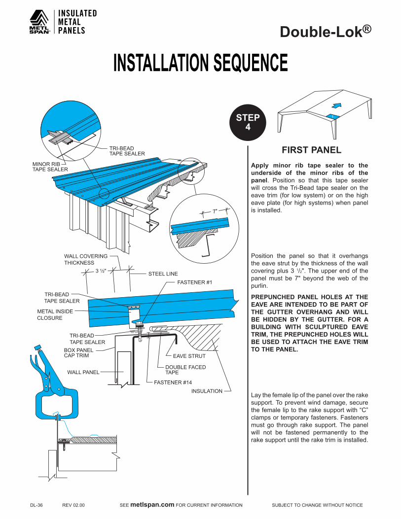
INSTALLATION SEQUENCEDouble-Lok®
DL-36REV02.00SEEmetlspan.comFORCURRENTINFORMATIONSUBJECTTOCHANGEWITHOUTNOTICE
FIRST PANELApply minor rib tape sealer to the underside of the minor ribs of the panel. Position so that this tape sealer willcross theTri-Bead tapesealeron theeave trim (for lowsystem)oron thehigheaveplate(forhighsystems)whenpanelis installed.
Position the panel so that it overhangs the eave strut by the thickness of the wall coveringplus31/2".Theupperendof thepanelmust be 7" beyond theweb of thepurlin.
PREPUNCHED PANEL HOLES AT THE EAVE ARE INTENDED TO BE PART OF THE GUTTER OVERHANG AND WILL BE HIDDEN BY THE GUTTER. FOR A BUILDING WITH SCULPTURED EAVE TRIM, THE PREPUNCHED HOLES WILL BE USED TO ATTACH THE EAVE TRIM TO THE PANEL.
Laythefemalelipofthepanelovertherakesupport. To prevent wind damage, secure thefemaleliptotherakesupportwith“C”clamps or temporary fasteners. Fasteners must go through rake support. The panel will not be fastened permanently to the rake support until the rake trim is installed.
1STEP4
EAVE STRUT
WALL PANEL
TRI-BEADTAPE SEALER
METAL INSIDECLOSURE
STEEL LINE
WALL COVERINGTHICKNESS
3 ¹⁄₂"
FASTENER #1
TRI-BEADTAPE SEALER
INSULATION
DOUBLE FACEDTAPE
FASTENER #14
BOX PANELCAP TRIM
7"
TRI-BEADTAPE SEALER
MINOR RIBTAPE SEALER

INSTALLATION SEQUENCEDouble-Lok®
SUBJECTTOCHANGEWITHOUTNOTICESEEmetlspan.comFORCURRENTINFORMATIONREV02.00DL-37
1STEP4
CONT.
FIRST PANELAttach the panel to the eave strut and metal inside closures with Fastener #1E.Eight fasteners are required at thislocation.
NOTE: IT IS ESSENTIAL THAT THE ERECTOR MAINTAIN A 24" MODULE AT THE EAVE, WITH THE PROPER INSTALLATION OF THE INSIDE CLOSURES AND BY INSTALLING FASTENERS IN THE PROPER SEQUENCE.
2 8 7 6 5 431
FASTENER #1EALL LOCATIONS
CAUTIONDo not, under any circumstance, step on the panel at the seam or at the panel ends until the adjacent side, end panels or eave fasteners are fully attached. The roof panel may not support the weight of a man at these locations and could affect panel module.
CAUTIONThe roof should be swept clean of any drill shavings at the end of each day to prevent rust.

INSTALLATION SEQUENCEDouble-Lok®
DL-38REV02.00SEEmetlspan.comFORCURRENTINFORMATIONSUBJECTTOCHANGEWITHOUTNOTICE
BACk-UP PLATE
Slide a back-up plate onto end of panel; make sure the teeth on top of the back-upplateareontopofthepanel.Visuallycheck to see that the holes in the panel align with the holes in the back-up plate.
PlaceTri-Beadtapesealerovertheentirewidth of the panel. It must be centered directly over the pre-punched holes, following the panel configuration.
1STEP5
NOTEAll back-up plates on first panel run will require field modification to avoid fouling rake support.
CAUTIONForcing the tape sealer back into the corners will lessen the thickness of the tape sealer where it is needed most.
LOW SYSTEM HIGH SYSTEM(FIRST RUN ONLY)
CUT ANDREMOVE
CUT ANDREMOVE
CUT ANDBEND
TAPE SEALERON MALE LEG
RIGHT WAY WRONG WAY
FIELD MODIFY
CUT ANDREMOVE

INSTALLATION SEQUENCEDouble-Lok®
SUBJECTTOCHANGEWITHOUTNOTICESEEmetlspan.comFORCURRENTINFORMATIONREV02.00DL-39
CLIP INSTALLATIONBefore installing the first clip, clamp themale side of the panel to the side of the back-up plate with a pair of Vise-Grip® locking pliers. This will help maintain panel module at the endlaps.
Install a clip on the male leg of the panel at the endlap. This should be the first clip installed as it controls the 24" module for the remainder of the panel. Remove Vise-Grip® locking pliers and install clips on all remaining purlins.
1STEP6
CAUTIONThe panel clip has factory applied mastic in the upper lip. This mastic is compressed when the clip is rotated in place. If, for some reason, a clip must be removed, a new clip must be used.
24"
FASTENER #1
• Position the clip over the male leg of the panelas shown, and rotate clip downward.
• With the uppper clip firmly seated, position the base firmly against the purlin flange.
• When properly positioned, the vertical legs of the upper and lower sections of the clip will be pointedupward, as shown.
FASTENER REQUIREMENTSPurlins-Fastener#1or#1F
Joists-Fastener#6(Twofastenersperclip)
CAUTIONForUL90Roofs,seePageDL-4.
IMPORTANTAseach clip is installed,maintain a 24"panel module.

INSTALLATION SEQUENCEDouble-Lok®
DL-40REV02.00SEEmetlspan.comFORCURRENTINFORMATIONSUBJECTTOCHANGEWITHOUTNOTICE
12STEP
7
CAUTIONThe roof should be swept clean of any drill shavings at the end of each day to prevent rust.
ENDLAP
Position female lip of upper panel over rake support, while holding male side of panel up away from the tape sealer. Using an awl, align the hole nearest the female side of the top panel with the corresponding hole in the lower panel and the back-up plate.
Once this is accomplished, rotate the male side of the upper panel down to rest on the Vise-Grip® locking pliers.
Make sure the panel notches are aligned.
Remove awl and insert in the middle hole nearestthemaleleg.InstallFastener#1Ein the hole by the female leg.
DOWN SLOPE
3"4"
PANEL CLIP
TRI-BEADTAPE SEALANT
FASTENER #1
(2 REQUIRED)
3"
3"
NOTEStep7appliesonlywheremorethanonepanel is used in a single slope.

INSTALLATION SEQUENCEDouble-Lok®
SUBJECTTOCHANGEWITHOUTNOTICESEEmetlspan.comFORCURRENTINFORMATIONREV02.00DL-41
12STEP
8
ENDLAP
All holes in the upper and lower panels and the back-up plate should now be aligned with each other.
Install Fastener #1E in sequence 2, 3and the hole left by the awl after it is removed(4).Next,removetheVise-Grip® lockingpliersandinstallFastener#1Einpositions5,6,7and8.
To ensure that the male legs do not separate at the panel endlap, clamp the horizontal ledge with a “C” clamp untilthe endlap is fastened together. Apply Tri-Bead tape sealer over the notched portion of these male legs.
Repeat the endlap procedures as required for each panel untill the ridge or high eave is reached.
17 8
FASTENER #1EALL LOCATIONS
³⁄₄"
TRI-BEADTAPE SEALER
FASTENER SEQUENCEFIRST RUN - ENDLAP
FASTENER #1E
5
4
3 62
3"
NOTEStep8appliesonlywheremorethanonepanel is used in a single slope.

INSTALLATION SEQUENCEDouble-Lok®
DL-42REV02.00SEEmetlspan.comFORCURRENTINFORMATIONSUBJECTTOCHANGEWITHOUTNOTICE
3 21STEP
9
CAUTIONInstalling the tape sealer to the male leg attheridgeisimportant.Withoutit,watercould be driven behind the outside closure by a strong wind.
RIDGE PANEL
NOTEAll back-up plates on first panel runwill require field modification to avoidfouling rake support.
At the ridge, install a back-up plate as in Step5.Theback-upplateisnecessarytomaintain panel module.
Install Fastener #1E upslope from theholes at each side of the panel. Fasteners should be at the edge of the panel. This will help maintain panel modularity at the ridge.
Install Tri-Bead tape sealer across theprofile of the male leg at the ridge. This tape sealer will be centered 1 1/2" fromthe end of the panel, which is also in alignment with the prepunched holes. DO NOT INSTALL TAPE SEALER ACROSS PANEL AT RIDGE AT THIS TIME.
InstallclipsonridgepanelasinStep6.
FASTENER #1E
FASTENER #1E
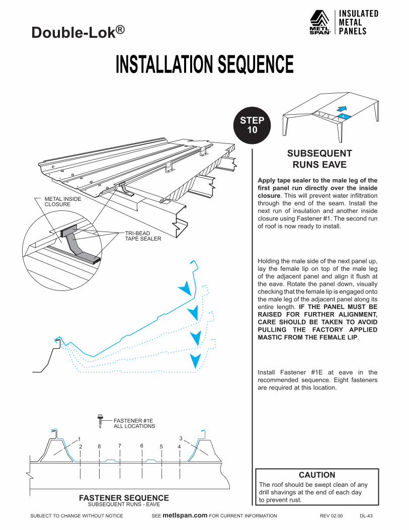
INSTALLATION SEQUENCEDouble-Lok®
SUBJECTTOCHANGEWITHOUTNOTICESEEmetlspan.comFORCURRENTINFORMATIONREV02.00DL-43
43 2
1STEP10
SUBSEQUENT RUNS EAVE
Apply tape sealer to the male leg of the first panel run directly over the inside closure. This will prevent water infiltration through the end of the seam. Install the next run of insulation and another insideclosureusingFastener#1.Thesecondrunof roof is now ready to install.
Holdingthemalesideofthenextpanelup,lay the female lip on top of the male leg of the adjacent panel and align it flush at the eave. Rotate the panel down, visually checking that the female lip is engaged onto the male leg of the adjacent panel along its entire length. IF THE PANEL MUST BE RAISED FOR FURTHER ALIGNMENT, CARE SHOULD BE TAkEN TO AVOID PULLING THE FACTORY APPLIED MASTIC FROM THE FEMALE LIP.
Install Fastener #1E at eave in therecommended sequence. Eight fastenersare required at this location.
CAUTIONThe roof should be swept clean of anydrill shavings at the end of each dayto prevent rust.
12 8 7 6 5 4
3
FASTENER #1EALL LOCATIONS
TRI-BEADTAPE SEALER
METAL INSIDECLOSURE
FASTENER SEQUENCESUBSEQUENT RUNS - EAVE

INSTALLATION SEQUENCEDouble-Lok®
DL-44REV02.00SEEmetlspan.comFORCURRENTINFORMATIONSUBJECTTOCHANGEWITHOUTNOTICE
54
32
1STEP11
SUBSEQUENT RUNS ENDLAP
Install back-up plate and tape sealer as in Step 5. However, on this and allsubsequent runs, care must be taken to engage the tab on the side into the slot of the adjacent back-up plate. This procedurewillassist inmaintaininga24"panel module.
InstallclipsasdescribedinStep6.
Install upper panel as described in Step 7&8.
Repeat the endlap procedures as required for each panel until the ridge is reached.
17 8
FASTENER #1EALL LOCATIONS
FASTENER SEQUENCESUBSEQUENT RUNS - ENDLAP
5
4
3 62
COMPLETE ENGAGEMENTOF BACK-UP PLATES
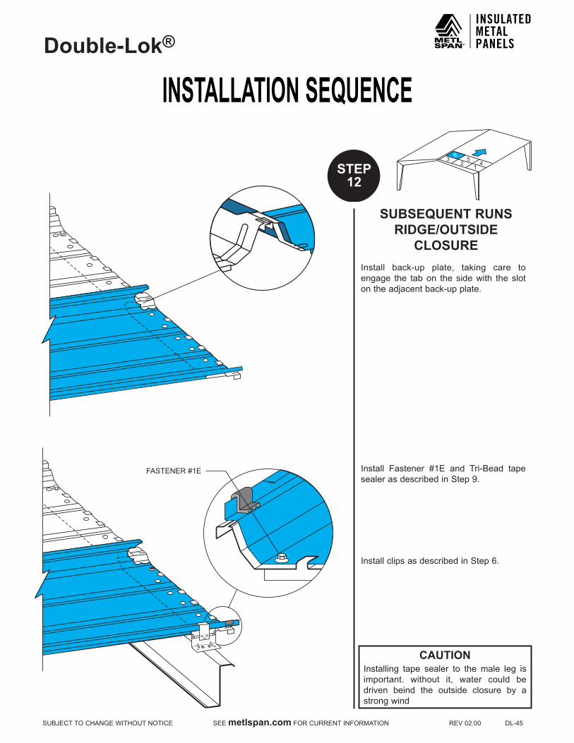
INSTALLATION SEQUENCEDouble-Lok®
SUBJECTTOCHANGEWITHOUTNOTICESEEmetlspan.comFORCURRENTINFORMATIONREV02.00DL-45
43
126
5
STEP12
CAUTIONInstalling tape sealer to the male leg is important. without it, water could be driven beind the outside closure by a strong wind
SUBSEQUENT RUNS RIDGE/OUTSIDE
CLOSUREInstall back-up plate, taking care to engage the tab on the side with the slot on the adjacent back-up plate.
Install Fastener #1E and Tri-Bead tapesealerasdescribedinStep9.
InstallclipsasdescribedinStep6.
FASTENER #1E

INSTALLATION SEQUENCEDouble-Lok®
DL-46REV02.00SEEmetlspan.comFORCURRENTINFORMATIONSUBJECTTOCHANGEWITHOUTNOTICE
SEAMING PANEL SIDELAPS
The seamer comes in a specially designed box accompanied by a field manualand a hand seaming tool. READ THE SEAMER MANUAL THOROUGHLY BEFORE STARTING THE SEAMING OPERATION. FAILURE TO ADHERE TO THESE INSTRUCTIONS MAY RESULT IN PERSONAL INJURY AND DAMAGE TO THE SEAMER AND/OR PANELS. THE ERECTOR WILL BE HELD LIABLE FOR ANY COSTS INCURRED FOR REPLACEMENT OR REPAIR.
PRE-SEAMING INFORMATION1.Locate seamer box. Assemble hand
seaming tool.2.Locatepowersourceandcheckagainst
power requirements in field manual.3.Checkseamsforproperengagement.4.Clean dirt, debris and excess sealant
from seams and panel surfaces to avoid interfering with the seaming operation.
5.Panelsdonothavetobeseamedastheyare installed. However, to prevent panel separation by a strong wind, panels should be seamed as soon as possible. ALL PANELS SHOULD BE SEAMED AT THE END OF EACH DAY.
SEAMING OPERATION
To determine the direction of the seaming process, stand at the eave and look upslope. If the roof is being installed from left to right, the seamer will run from ridge to eave. If the roof is being installed from right to left, the seamer will run from eave to ridge.
INSPECTION OF SEAM
A visual inspection of the seam should be made to determine if the seam is forming properly. Check seam against the crosssection provided. IF THE SEAMER IS NOT PRODUCING A FINISHED SEAM IDENTICAL TO THE CROSS SECTION PICTURED, STOP AT ONCE AND CALL Metl-Span AT 877-585-9969.
STEP13
DIRECTIONOF ROOFINSTALLATION
DIRECTIONOF ROOF
INSTALLATION
⁵⁄₈" ¹⁄₁₆"
³⁄₈" ¹⁄₁₆"
Cross Section of Finished Seam(Actual Size)

INSTALLATION SEQUENCEDouble-Lok®
SUBJECTTOCHANGEWITHOUTNOTICESEEmetlspan.comFORCURRENTINFORMATIONREV02.00DL-47
STEP13
CONT.SEAMING
OPERATION
CAUTIONIt is critical that the panel seams are crimped and folded as shown before using the electric seamer. Failure to follow these guidelines will result in damaged seams.
To begin seaming with hand tool, set the hand tool on the seam making sure seam is in the PHASE 1 ACTION slot. Align the edge of the hand tool with the end of the panel. Rotate the forming arm under the handle toproduce6"ofPHASE 1 seam. This should be done four times along the seamforatotalof24"
Return to the end of the panel to begin PHASE 2 ACTION. Set hand tool onto seam making sure seam is in the PHASE 2 ACTION slot. Align the edge of the hand tool with the end of the panel. Rotate the forming arm under the handle to produce 6"offinishedPHASE 2 seam. This should be done once per rib. The relationship of this 6" of finished seam to the 24" of crimped seam is critical to the proper alignment of the rolls in the electric seamer.
The seam is now ready to accept the electric seamer.
BEGINNINGPHASE 2 ACTION
FINISHEDPHASE 2 ACTION
BEGINNINGPHASE 1 ACTION
FINISHEDPHASE 1 ACTION
FORMINGARM
FORMINGARMGREASE
FITTINGS
HANDLE HANDLE
FORMINGARM
FORMINGARMGREASE
FITTINGS
HANDLE HANDLE
PHASE 2 ACTION(FINISHED SEAM)
PHASE 1 ACTION(FEMALE LIP CRIMPED)
6" 24"

INSTALLATION SEQUENCEDouble-Lok®
DL-48REV02.00SEEmetlspan.comFORCURRENTINFORMATIONSUBJECTTOCHANGEWITHOUTNOTICE
STEP13
CONT.
SEAMING OPERATIONSet seamer on seam with the locking arm up and to open side of the seam. The rear wheels should be at the edge of the panel.
Check to see that the last roll of theseamer is on the finished portion of the seam and the other rolls are on the crimped portion of the seam. Push the locking arm down to engage the rolls and turn the seamer on.
Note: While seamer is running, walk infront of seamer applying foot pressure to top of panel seam while paying attention to end of panel run.
Stop seamer about one foot from ridge. Disengage locking arm and remove the electric seamer.
Finish seam with hand tool by first crimping the remaining portion of female lip. Then, using the second stage of the hand tool, fold and finish the seam. Repeat this procedure for all panels.
STAGES 1 AND 2 (FINISHED SEAM)
STAGE 1 ONLY (FEMALE LIP CRIMPED)
6"
18"
SEAMING DIRECTION
LOCKING ARM
CAUTIONSeamermotor is equippedwith 15 ampcircuit breaker.Extension cordwire sizemust be 10 gauge and no longer than200'frompowersource.
The manufacturer will not be responsible for motor damage if above instructions are not adhered to.
CAUTIONSeamer operation should be closely supervised at all times. A safety cable should be attached to the seamer.
IF DIFFICULTY ARISES USING THE SEAMING MACHINE, PLEASE CALL 877-713-6224 EXT. 28069

INSTALLATION SEQUENCEDouble-Lok®
SUBJECTTOCHANGEWITHOUTNOTICESEEmetlspan.comFORCURRENTINFORMATIONREV02.00DL-49
56
43
21
STEP14
CAUTIONThe seamer will not support itself while flattening the male leg on the last run. It must be supported during this operation.
LAST PANEL RUNThis roof system is designed to finish in the highonevenfootagebuildingsbyusing24"or18"panelsonthelastrun.
Withinsulationinplace,installrakesupportalong steel line.
FINISHING ON MODULEIf your roof is finishing on module, the male leg of the last panel run will need to be flattened before installation, with the exception of the first and the last 6" ofeach panel. This will allow for proper panel engagement at endlaps once panels are installed. Use the hand tool to flatten the male leg 6" from the starting end. (Referto legend plate on seamer to determine the end that the seamer will start from.)With locking bar up, place seamer onmale leg so that the last two rolls of the seamer are on the flattened portion of the seam. The first two rolls will be under the unflattened portion of the seam. Lowerlockingbarand runseamer towithin6"ofthe end of the panel. Raise locking bar and remove seamer. Repeat this procedure for all panels. Install panels as usual. Use hand tool to finish the unflattened portion of the male leg at the eave, ridge and endlaps.
FINISHING OFF MODULEIfthepanelends4"-8"awayfromtherakesupport due to an out-of-square condition or other factors, simply install the panel clips and run seamer over male leg. This will lock the clips in place and flatten the male leg. This system allows for the roof to be trimmed in the high.
6"
9"
6"
6" START SEAMER6" FROM ENDOF PANEL
6"
6"
DO NOT CRIMP THIS AREA
SEAMER DIRECTION
PREPARING PANEL FOR SEAMER WITH HAND TOOL
8" MAX
4" MIN
RAKE SUPPORT
STEEL LINE
FLATTENING MALE LEG BEFORE PANEL INSTALLATION
STOP SEAMER 6" FROM END OF PANEL
FLATTEN WITH HAND TOOL
VARIABLE TERMINATION TRIM
MINIMUM 1" RAKE TRIM
FOLD BACK VINYL
FINISHING WITH HAND TOOL AFTER PANEL
INSTALLATION
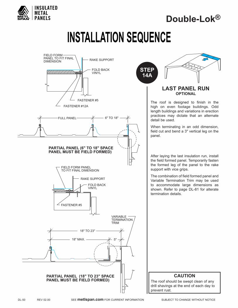
INSTALLATION SEQUENCEDouble-Lok®
DL-50REV02.00SEEmetlspan.comFORCURRENTINFORMATIONSUBJECTTOCHANGEWITHOUTNOTICE
56
43
21STEP
14A
CAUTIONThe roof should be swept clean of anydrill shavings at the end of each day toprevent rust.
LAST PANEL RUN OPTIONAL
The roof is designed to finish in the high on even footage buildings. Odd length buildings and variations in erection practices may dictate that an alternate detail be used.
When terminating in an odd dimension,fieldcutandbenda3"verticallegonthepanel.
After laying the last insulation run, install the field formed panel. Temporarily fasten the formed leg of the panel to the rake support with vice grips.
The combination of field formed panel and Variable Termination Trim may be usedto accommodate large dimensions as shown.Refer topageDL-81 foralteratetermination details.
RAKE SUPPORT
FIELD FORM PANELTO FIT FINAL DIMENSION
FOLD BACKVINYL
FASTENER #5
RAKE SUPPORTFIELD FORMPANEL TO FIT FINALDIMENSION
FOLD BACKVINYL
FASTENER #5
FASTENER #12A
6" TO 18"FULL PANEL
PARTIAL PANEL (6" TO 18" SPACEPANEL MUST BE FIELD FORMED)
18" MAX. 5"
18" TO 23"
PARTIAL PANEL (18" TO 23" SPACEPANEL MUST BE FIELD FORMED)
VARIABLETERMINATIONTRIM

INSTALLATION SEQUENCEDouble-Lok®
SUBJECTTOCHANGEWITHOUTNOTICESEEmetlspan.comFORCURRENTINFORMATIONREV02.00DL-51
STEP15
OUTSIDE CLOSUREAfter all panel runs are installed and seamed, return to first panel run at the ridge.InstallTri-Beadtapesealeracrossfull width of each panel, covering the prepunched holes.
Rotate outside closure into position contacting the female side of the panel first. Using an awl, align the first hole on the female side of the outside closure with the corresponding hole in the panel and back-up plate. Remove the awl and installFastener#1Einthishole.
Push the other end of the outside closure into position and align the holes with the awl. Remove the awl and install Fastener #1Einallremainingholesexceptforthehole at the panel seam. Do not install the panel seam fastener at this time.
Install all outside closures on both sides of the ridge.
If the last panel run was field modified, the final outside closure on the last panel will require field modification as well. A tab should be formed on the end of the outside closure for attachment to theupturned legof the roofpanel (fieldformed). This tab should be attachedto the panel with Fastener #1E, tworequired.
InstallFastener#1Einremainingholeatthe panel seam of all outside closures. The fastener installed in the top hole must go through the panel seam and the corresponding hole of the adjacent outside closure.
Use urethane sealant to fill any voids around panel seam on upslope side of outside cosure.
FASTENER #1E
FASTENER #1E
TAPE SEALANTBACK-UP PLATE(FIELD MODIFIED)
RAKESUPPORT
UPTURNED PANEL LEGFIELD FORMED TAB
FASTENER #1E (2 REQUIRED)FIELD CUT AND BEND
TAPE SEALANT
FASTENER #1E
FASTENER #1EURETHANESEALANT ASREQUIRED
URETHANE SEALANTBETWEEN OUTSIDECLOSURE TABS

INSTALLATION SEQUENCEDouble-Lok®
DL-52REV02.00SEEmetlspan.comFORCURRENTINFORMATIONSUBJECTTOCHANGEWITHOUTNOTICE
56
43
21STEP
16
RIDGE-OUTSIDE CLOSURE/FLASHING
ApplyTri-Beadtapesealertothetopofthe outside closure.
Install the ridge flashing starting and ending11/4"pluswallthicknessoutsidethe steel line. Fasten the ridge flashing to theoutsideclosureswithFastener#4.Installafastener11/2"frompanelseamon both sides of panel. Install additional fasteners directly above minor ribs of panel. Four fasteners are required at each panel.Leave6"unfastenedoneachendto allow for the rake trim to be installed later. DO NOT FASTEN THROUGH THE LOCk OF THE STANDING SEAM.
ForfloatingpeakboxinstallationseepageDL-80.
TRI-BEADTAPE SEALER
URETHANE SEALANTAS REQUIRED
6" MINIMUM
TRI-BEADTAPE SEALER
FASTENER #4
OUTSIDECLOSURE
1 ¹⁄₄" PLUS WALLTHICKNESS
RIDGE FLASH
OUTSIDECLOSURE
FASTENER #4
1 ¹⁄₂ "
Tri-BeadTape Sealer
1 ¹⁄₂ "RIDGE FLASH
1¹⁄₂" 7" 7" 7"
24"

SPECIAL ERECTION TECHNIQUESDouble-Lok®
SUBJECTTOCHANGEWITHOUTNOTICESEEmetlspan.comFORCURRENTINFORMATIONREV02.00DL-53
RECOMMENDED ERECTION PRACTICES
CORRECTING OUT-OF-PLANE SUBSTRUCTURE
Occasionally a purlin may be encountered that islower(out-of-plane)thanthoseadjacenttoit.Whenaclipisattachedtothispurlin,itwillgo down further than those adjacent to it, distortingtheseam.Thiscancausethenextpanel sidelap to be difficult to lap together in this area. To compensate for this lower purlin, a steel shim may be placed under the clip to bringituptotheproperheight(inplane).Thisshim should be no thicker than 1/4". If 1/4" isnot enough, then structural modification will be necessary.
Avoid “stair-stepping” of the panels at theeave. This will cause problems engaging back-up plates at the endlap and ridge. Any “stripped out” fasteners at the endlapsor outside closures should be immediately replaced with Fastener #2A. Place a 1"long piece of tri-bead tape sealer over the “strippedout”holebeforeinstallingFastener#2A.Thiswillallowthefastenerthreadstobecoated with tape sealer and provide a good seal.
NEVER ALLOW PANELS TO COME INTO CONTACT WITH LEAD, COPPER, GRAPHITE, GASOLINE OR OTHER HARSH CHEMICALS AS THIS WILL VOID THE GALVALUME® WARRANTY.
CHECk ROOF FOR PANEL ALIGNMENT
Check the roof every three or four runs forpanel alignment as it is being erected. This can be accomplished by two different means.1.Measure from the rake support to the
seam of the last completed panel run. Take measurements at the ridge, eave, and all endlaps.
2.Attach a stringline to the eave plate andridge purlin, running parallel to the rake support. The stringline should stay ahead of the work and can be moved across the roof as construction progresses. Measure from the stringline back to the last completed panel run. Take measurements at the ridge, eave, and all endlaps.
STEEL SHIM
x
x
EAVE STRUT
PEAKPURLIN
X
FIRST PANEL LAST COMPLETEDPANEL RUN
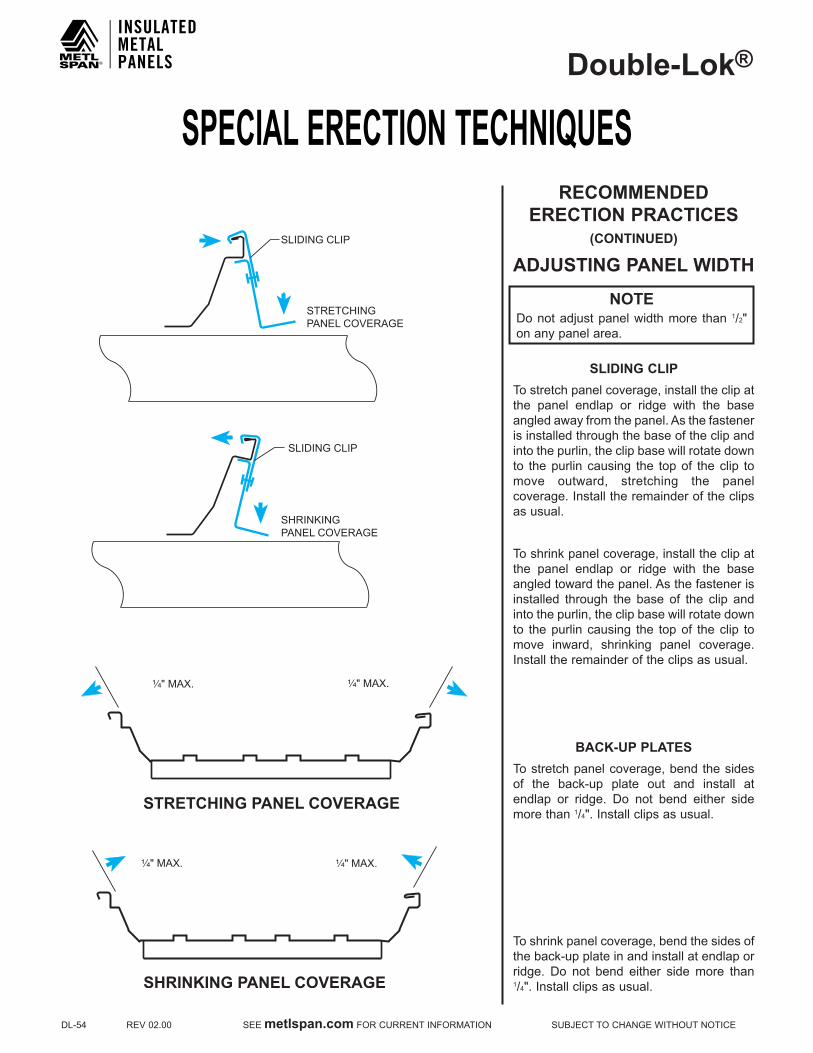
SPECIAL ERECTION TECHNIQUESDouble-Lok®
DL-54REV02.00SEEmetlspan.comFORCURRENTINFORMATIONSUBJECTTOCHANGEWITHOUTNOTICE
RECOMMENDED ERECTION PRACTICES
(CONTINUED)
ADJUSTING PANEL WIDTH
SLIDING CLIPTo stretch panel coverage, install the clip at the panel endlap or ridge with the base angled away from the panel. As the fastener is installed through the base of the clip and into the purlin, the clip base will rotate down to the purlin causing the top of the clip to move outward, stretching the panel coverage. Install the remainder of the clips as usual.
To shrink panel coverage, install the clip at the panel endlap or ridge with the base angled toward the panel. As the fastener is installed through the base of the clip and into the purlin, the clip base will rotate down to the purlin causing the top of the clip to move inward, shrinking panel coverage. Install the remainder of the clips as usual.
BACk-UP PLATESTo stretch panel coverage, bend the sides of the back-up plate out and install at endlap or ridge. Do not bend either side more than 1/4".Installclipsasusual.
To shrink panel coverage, bend the sides of the back-up plate in and install at endlap or ridge. Do not bend either side more than 1/4".Installclipsasusual.
NOTEDo not adjust panel width more than 1/2"on any panel area.
¹⁄₄" MAX. ¹⁄₄" MAX.
STRETCHING PANEL COVERAGE
SHRINKINGPANEL COVERAGE
SLIDING CLIP
SLIDING CLIP
STRETCHINGPANEL COVERAGE
¹⁄₄" MAX. ¹⁄₄" MAX.
SHRINKING PANEL COVERAGE
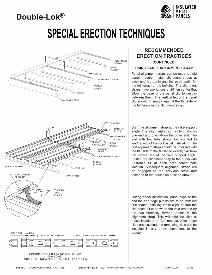
SPECIAL ERECTION TECHNIQUESDouble-Lok®
SUBJECTTOCHANGEWITHOUTNOTICESEEmetlspan.comFORCURRENTINFORMATIONREV02.00DL-55
RECOMMENDED ERECTION PRACTICES
(CONTINUED)USING PANEL ALIGNMENT STRAP
Panel alignment straps can be used to hold panel module. Install alignment straps at each end lap purlin and the peak purlin for the full length of the building. The alignment strapshavetwolancesat24"oncenterthatallow the base of the panel clip to nest in between them. The vertical leg of the panel clip should fit snugly against the flat side of the tall lance in the alignment strap.
Start the alignment strap at the rake support angle. The alignment strap has two tabs on one end and one tab on the other end. The end with two tabs should be oriented to leading end of the roof panel installation. The first alignment strap should be installed with theflatsideofthetalllanceexactly24"fromthe vertical leg of the rake support angle. Fasten the alignment strap to the purlin with Fastener #1 at each prepunched holelocation. Subsequent alignment straps will be engaged to the previous strap and fastened to the purlins as outlined above.
During panel installation, panel clips at the end lap and ridge purlins are to be installed first.Wheninstallingtheseclips,ensuretheclip bases fit in between the void created by the two vertically formed lances in the alignment strap. This will hold the clips at these locations on 24" module.After theseclips are installed, the remaining clips can be installed in any order convenient to the erector.
TRI-BEADTAPE SEALER
3" LAP
EAVE STRUT
FIELD CUT VARIESOF STARTING SIDELAP DIRECTION OF INSTALLATION
OPTIONAL PANEL CLIP ALIGNMENT STRAP(6’-0” LONG)
LOCATED AT ENDLAP PURLIN AND THE PEAK PURLIN
CL
PURLIN
ENDLAPPURLIN
BACK-UPPLATE
ALIGNMENT STRAP
BACK-UPPLATE
PANEL CLIP
ALIGNMENTSTRAP
PEAKPURLIN
EAVE TRIM
TRI-BEADTAPESEALER
METAL INSIDECLOSURE
EAVE STRUT
PURLIN
PURLIN
ENDLAPPURLIN
ALIGNMENT STRAP
ALIGNMENTSTRAP
PEAKPURLIN
24"
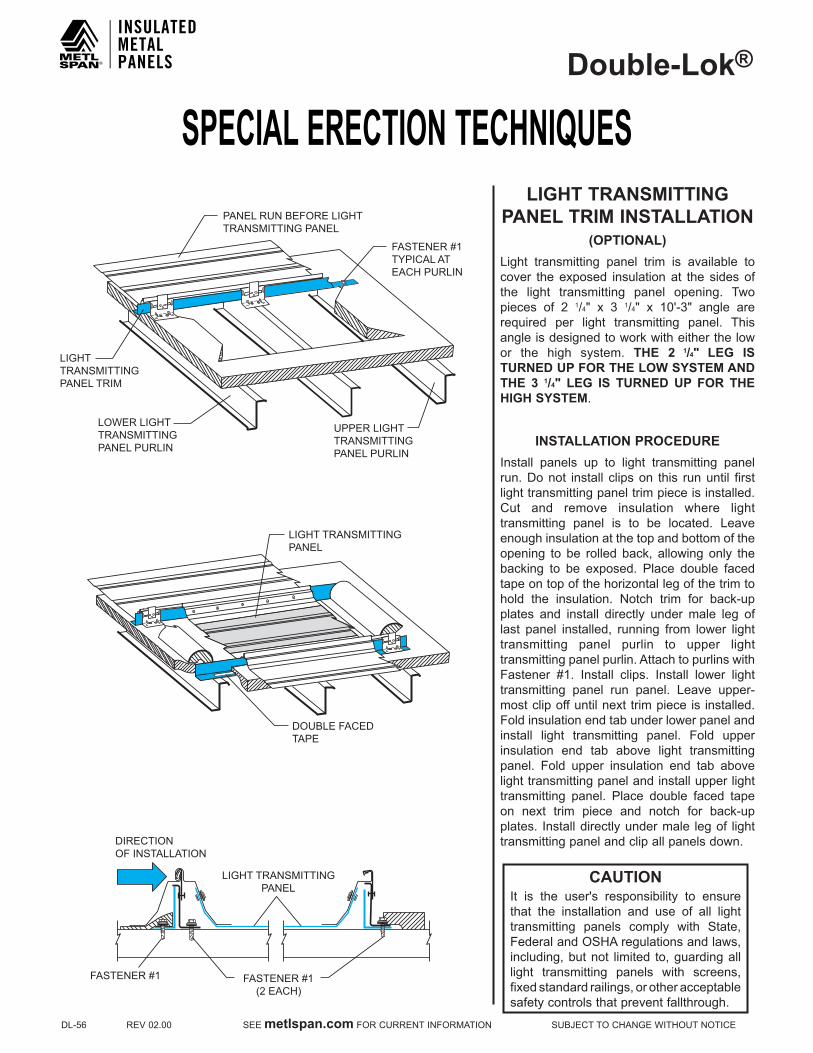
SPECIAL ERECTION TECHNIQUESDouble-Lok®
DL-56REV02.00SEEmetlspan.comFORCURRENTINFORMATIONSUBJECTTOCHANGEWITHOUTNOTICE
CAUTIONIt is the user's responsibility to ensurethat the installation and use of all light transmitting panels comply with State, Federal and OSHA regulations and laws, including, but not limited to, guarding all light transmitting panels with screens, fixedstandardrailings,orotheracceptablesafety controls that prevent fallthrough.
LIGHT TRANSMITTING PANEL TRIM INSTALLATION
(OPTIONAL)Light transmitting panel trim is available tocover theexposed insulationat the sidesofthe light transmitting panel opening. Two pieces of 2 1/4" x 3 1/4" x 10'-3" angle arerequired per light transmitting panel. This angle is designed to work with either the low or the high system. THE 2 1/4" LEG IS TURNED UP FOR THE LOW SYSTEM AND THE 3 1/4" LEG IS TURNED UP FOR THE HIGH SYSTEM.
INSTALLATION PROCEDUREInstall panels up to light transmitting panel run. Do not install clips on this run until first light transmitting panel trim piece is installed. Cut and remove insulation where lighttransmitting panel is to be located. Leaveenough insulation at the top and bottom of the opening to be rolled back, allowing only the backing to be exposed. Place double facedtape on top of the horizontal leg of the trim to hold the insulation. Notch trim for back-up plates and install directly under male leg of last panel installed, running from lower light transmitting panel purlin to upper light transmitting panel purlin. Attach to purlins with Fastener #1. Install clips. Install lower lighttransmitting panel run panel. Leave upper-mostclipoffuntilnexttrimpieceis installed.Fold insulation end tab under lower panel and install light transmitting panel. Fold upper insulation end tab above light transmitting panel. Fold upper insulation end tab above light transmitting panel and install upper light transmitting panel. Place double faced tape on next trim piece and notch for back-upplates. Install directly under male leg of light transmitting panel and clip all panels down.
FASTENER #1 TYPICAL AT EACH PURLIN
PANEL RUN BEFORE LIGHT TRANSMITTING PANEL
LIGHT TRANSMITTING PANEL TRIM
LOWER LIGHT TRANSMITTING PANEL PURLIN
UPPER LIGHT TRANSMITTING PANEL PURLIN
DIRECTION OF INSTALLATION
LIGHT TRANSMITTING PANEL
FASTENER #1 (2 EACH)
FASTENER #1
LIGHT TRANSMITTING PANEL
DOUBLE FACED TAPE

SPECIAL ERECTION TECHNIQUESDouble-Lok®
SUBJECTTOCHANGEWITHOUTNOTICESEEmetlspan.comFORCURRENTINFORMATIONREV02.00DL-57
FIELD LOCATED LTP INSTALLATION DIRECTIONS
The Field Located LTP can be installed atany time, either during roof installation or after the roof has been completed. The Field Located LTP may be installed almostanywhere intheroof.TheLTPmust involveat least two purlin spans and must be at least 5'fromtheeave,ridgeorrake.
Once the Field Located LTP location isdetermined,verifytheexactpurlinlocationattheupslopeanddownslopeendsoftheLTP.Cut out the panel flat as shown in theadjacent drawings. At the up slope end only, notch out the panel ribs as shown.
The opening for an LTP on a roof with 5'purlinspacingwillmeasure9'-9"longby18"wide. The opening at the down slope end will be7"fromthewebofthepurlin.Theopeningattheupslopeendwillbe4"fromthewebofthe purlin.
REMOVEPAN ONLY
3"
18"
1/2"
AA
SECTION A-A
PANEL CROSS SECTION
ROOF PANEL
REMOVE PAN ONLY
9'-9" OPENING
7"
4"
RO
OF
SLO
PE
3"18"3"
CE
NTE
R L
INE
PA
NE
L R
IB
CE
NTE
R L
INE
PA
NE
L R
IB
(BA
SE
D O
N N
OM
INA
L 5'
-0" P
UR
LIN
SPA
CIN
G)
9'-9
"7"
4"
TO B
E R
EM
OV
ED
DO
NO
T ST
EP
5 '-0
"N
OM
INA
L5'
-0"
NO
MIN
AL
PURLIN
PURLIN
WEB OFPURLIN
PURLIN
24"
WEB OFPURLIN
CAUTIONIt is the user's responsibility to ensurethat the installation and use of all light transmitting panels comply with State, Federal and OSHA regulations and laws, including, but not limited to, guarding all light transmitting panels with screens, fixedstandardrailings,orotheracceptablesafety controls that prevent fallthrough.
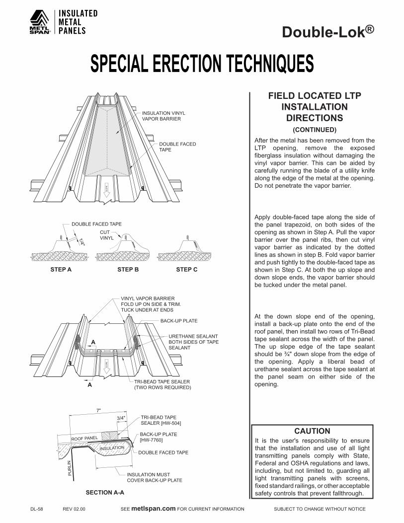
SPECIAL ERECTION TECHNIQUESDouble-Lok®
DL-58REV02.00SEEmetlspan.comFORCURRENTINFORMATIONSUBJECTTOCHANGEWITHOUTNOTICE
FIELD LOCATED LTP INSTALLATION DIRECTIONS
(CONTINUED)After the metal has been removed from the LTP opening, remove the exposedfiberglass insulation without damaging the vinyl vapor barrier. This can be aided by carefully running the blade of a utility knife along the edge of the metal at the opening. Do not penetrate the vapor barrier.
Apply double-faced tape along the side of the panel trapezoid, on both sides of the opening as shown in Step A. Pull the vapor barrier over the panel ribs, then cut vinyl vapor barrier as indicated by the dotted linesasshowninstepB.Foldvaporbarrierand push tightly to the double-faced tape as showninStepC.Atboththeupslopeanddown slope ends, the vapor barrier should be tucked under the metal panel.
At the down slope end of the opening, install a back-up plate onto the end of the roofpanel,theninstalltworowsofTri-Beadtape sealant across the width of the panel. The up slope edge of the tape sealant shouldbe¾"downslopefromtheedgeofthe opening. Apply a liberal bead of urethane sealant across the tape sealant at the panel seam on either side of the opening.
CAUTIONIt is the user's responsibility to ensurethat the installation and use of all light transmitting panels comply with State, Federal and OSHA regulations and laws, including, but not limited to, guarding all light transmitting panels with screens, fixedstandardrailings,orotheracceptablesafety controls that prevent fallthrough.
INSULATION VINYLVAPOR BARRIER
DOUBLE FACEDTAPE
SLO
PE
SLO
PE
STEP A
SECTION A-A
A
A
STEP B STEP C
DOUBLE FACED TAPE
CUTVINYL1/4"
VINYL VAPOR BARRIERFOLD UP ON SIDE & TRIM.TUCK UNDER AT ENDS
BACK-UP PLATE
TRI-BEAD TAPE SEALER(TWO ROWS REQUIRED)
URETHANE SEALANTBOTH SIDES OF TAPESEALANT
INSULATION MUSTCOVER BACK-UP PLATE
DOUBLE FACED TAPE
7"3/4" TRI-BEAD TAPE
SEALER [HW-504]
BACK-UP PLATE[HW-7760]ROOF PANEL
PUR
LIN
INSULATION

SPECIAL ERECTION TECHNIQUESDouble-Lok®
SUBJECTTOCHANGEWITHOUTNOTICESEEmetlspan.comFORCURRENTINFORMATIONREV02.00DL-59
CAUTIONIt is the user's responsibility to ensurethat the installation and use of all light transmitting panels comply with State, Federal and OSHA regulations and laws, including, but not limited to, guarding all light transmitting panels with screens, fixedstandardrailings,orotheracceptablesafety controls that prevent fallthrough.
FIELD LOCATED LTP INSTALLATION DIRECTIONS
(CONTINUED)At the up slopeendof the LTP, install tworows of Tri-Bead tape sealant across itswidth, up to the horizontal shelf of the trapezoid. The up slope edge of the top run oftapesealantshouldbe¾"fromtheedgeoftheLTP.Applya3"longbeadofurethanesealant that covers the rest of the rib of the LTP andmarries to the tape sealant. ThisshouldbedoneonbothsidesoftheLTP.
Cut the "engagement flanges" off of bothsides of a back-up plate and install onto the upslopeendoftheLTP.
Liftthemetalroofpanelattheupslopeendof the opening. While the metal panel isliftedup,slide theupslopeendof theLTP(withtheback-upplateengagedonit)underthemetalpanelfor3".Oncethe3"endlaphas been achieved at the up slope end, lower the down slope end of the LTPontothe metal panel.
CAUTIONDo not step on the LTP panel. It is notdesigned to support the weight of a person.
3/4"UP HILL
3"
3" BACK-UP PLATE
CUT AND REMOVE
TRI-BEAD TAPE SEALER(TWO ROWS REQUIRED)LIGHT
TRANSMITTINGPANEL
ROOF PANEL
ROOF PANEL
BACK-UP PLATE
LIGHT TRANSMITTING PANEL
Slide
9'-9" OPENING
3"
7"
3"
4"
LIFTUP
SLIDEUNDER
LIGHT TRANSMITTINGPANEL
SLO
PE
BACK-UP PLATE
TRI-BEAD TAPE SEALER(TWO ROWS REQUIRED)
URETHANE SEALANTBOTH SIDES OF TAPESEALANT
URETHANE SEALANTBOTH SIDES
PANEL CROSS SECTION

SPECIAL ERECTION TECHNIQUESDouble-Lok®
DL-60REV02.00SEEmetlspan.comFORCURRENTINFORMATIONSUBJECTTOCHANGEWITHOUTNOTICE
CAUTIONIt is the user's responsibility to ensurethat the installation and use of all light transmitting panels comply with State, Federal and OSHA regulations and laws, including, but not limited to, guarding all light transmitting panels with screens, fixedstandardrailings,orotheracceptablesafety controls that prevent fallthrough.
FIELD LOCATED LTP INSTALLATION DIRECTIONS
(CONTINUED)At the up slope end of the LTP, install six#1Efastenersthroughthemetalpanel,LTPand into the back-up plate. Fasteners shouldbe1 1/2"upslope from theedgeofthe metal panel and spaced evenly across the flat of the panel as shown in the top two drawings.
AtthedownslopeendoftheLTP,installsix#43L fasteners through theLTP, themetalpanel and into the back-up plate. Fasteners shouldbe1 1/2"upslope from theedgeoftheLTPandspacedevenlyacross the flatof the panel as shown in the bottom two drawings.

SPECIAL ERECTION TECHNIQUESDouble-Lok®
SUBJECTTOCHANGEWITHOUTNOTICESEEmetlspan.comFORCURRENTINFORMATIONREV02.00DL-61
CAUTIONIt is the user's responsibility to ensurethat the installation and use of all light transmitting panels comply with State, Federal and OSHA regulations and laws, including, but not limited to, guarding all light transmitting panels with screens, fixedstandardrailings,orotheracceptablesafety controls that prevent fallthrough.
FIELD LOCATED LTP INSTALLATION DIRECTIONS
(CONTINUED)InstallTri-Bead tapesealant on the insideand along the full length of two repair caps. At each end of both repair caps, apply a liberal amount of urethane sealant in the rib and up both sides.
Install the repair caps to either side of the LTP. The repair caps should extend pastthe LTP an equal distance at both ends.While putting moderate foot pressure ontherepaircap,installFastener#4at6"oncenter. Fastener must penetrate through the tape sealant on the inside of the repair cap and into panel side cinching repair cap tight. It is best to pre-mark the fastener locations and start in the middle of the repair cap and work towards both ends installing the fasteners.
Whenrepaircapsareattached,inspecttheup slope end of each to insure that the urethane sealant completely sealed the repair cap to the panel and that there are no voids. If any voids are found, inject more urethane sealant into the area and finger wipe.

SPECIAL ERECTION TECHNIQUESDouble-Lok®
DL-62REV02.00SEEmetlspan.comFORCURRENTINFORMATIONSUBJECTTOCHANGEWITHOUTNOTICE
RIDGE VENTILATOR INSTALLATION
Turn ventilator over and place gently on its top. Note that the end cap is pre-formed for a1:12roofpitch.Thefivebenchmarkdotsrepresent 2:12, 3:12, 4:12, 5:12 and 6:12roof pitches. Draw a line between indicated corners and the appropriate dot for the roof pitch. Cut and remove that portion of theendcap.On5:12and6:12roofpitchesseeventmanufacturer’sspecial instructions forthe installation of the vent skirt. The end cap is now ready to receive the end skirt.
Positionendskirtontoendcap.Besurethedown-turned angle of the end skirt is inside of and up against the end cap. Attach end skirt toventilatorendcapwithFastener#4in four places.
PREFORMEDFOR A 1:12 PITCH
2:123:124:12
END CAPSCRIBE LINE
SIDE SKIRT
END SKIRT
FASTENER #4
END CAP
DAMPERCONTROL ARM
END CAP
5:126:12
NOTEMetl-Span does not recommend the use of a ridge ventilator on standing seam roofsystems.Sidewallorendwallexhaustfans or other ventilating methods should be considered. These details are for your convenience only. Only a 9" ridgeventilator can be used with this SSR system. Do not use ridge ventilators on anyroofover200'inwidthorwithaslopelessthan1:12orgreaterthan6:12.

SPECIAL ERECTION TECHNIQUESDouble-Lok®
SUBJECTTOCHANGEWITHOUTNOTICESEEmetlspan.comFORCURRENTINFORMATIONREV02.00DL-63
RIDGE VENTILATOR INSTALLATION
(CONTINUED)AfterTri-Beadtapesealerhasbeenappliedto top of outside closures, install ventilator in properlocation.Besuretocenterinopening.Attach ventilator to outside closures with Fastener#4on6"centers.Usetubesealantto seal between the outside of the ventilator and the end skirt.
Install the ridge flashing as in Step 16,except for those pieces on either side ofventilator. These will lay on top of, and seal to, the ventilator end skirt with a ridge end cap. Use Tri-Bead tape sealer to seal theridge end cap to the ridge flashing and the endskirt.UseFastener#4toinstalltheendcap.Sixfastenersarerequiredtotietheendcaptotheventilatorendskirt.Eightfastenersare required to tie the end cap to the ridge flashing.
For continuous ventilators, install end skirts on both ends of the first ventilator and one end of all following ventilators. Attach ventilator to outside closures as outlined above. Install an additional Fastener #4through the corner of the side skirt and into the end skirt.
Do not connect more than 4 vents to thesame linkage.
VENTILATOREND CAP
TUBE SEALANT
END SKIRT
FASTENER #4
URETHANESEALANT
FASTENER #4
RIDGE FLASHING
RIDGE END CAP
END SKIRT
FASTENER #4
END SKIRT
FASTENER #4
URETHANESEALANT
TRI-BEADTAPE SEALER

SPECIAL ERECTION TECHNIQUESDouble-Lok®
DL-64REV02.00SEEmetlspan.comFORCURRENTINFORMATIONSUBJECTTOCHANGEWITHOUTNOTICE
RIDGE VENTILATOR
TRI-BEADTAPE SEALER
FASTENER #1E(9 PER PANEL)INSULATION FASTENER #1
CLIP
BACK-UPPLATE
(6" O.FASTENER #4
C.)
OUTSIDECLOSURE
9"1'-4" 7"
RIDGE VENTILATOR
CAUTIONThis kit contains two end skirts which must be installed to support the ventilator.
NOTES:ONLY 9" RIDGE VENTILATORS CAN BE USED WITH THIS SSR SYSTEM. DO NOT USE RIDGE VENTILATORS ON ANY ROOF OVER 200' IN WIDTH OR WITH A SLOPE LESS THAN 1:12 OR GREATER THAN 6:12.

SPECIAL ERECTION TECHNIQUESDouble-Lok®
SUBJECTTOCHANGEWITHOUTNOTICESEEmetlspan.comFORCURRENTINFORMATIONREV02.00DL-65
VENTED RIDGE
9"2"
FASTENER #1(2 REQUIRED)
LOWPANEL CLIP
BACK-UP PLATE
(6 PER PANEL)FASTENER #1E
FASTENER #46" O.C.
TRI-BEADTAPE SEALER
Double-Lok®
PANEL
FASTENER #1E(3 PER PANEL)
PURLIN
1' - 4"
7"
VENT MATERIAL(INCLUDED WITHMETAL VENT)
METAL VENTHW-525
FASTENER #46" O.C.
OUTSIDECLOSURE
RIDGEFLASHING
9"2"
FASTENER #1(2 REQUIRED)
LOWPANEL CLIP
BACK-UP PLATE
FASTENER #1E
FASTENER #46" O.C.
TRI-BEADTAPE SEALER
FASTENER #1E(3 PER PANEL)
PURLIN
1' - 4"
7"
PERFORATEDVENT DRIPFL-254
FASTENER #46" O.C.
RIDGEFLASHING
OUTSIDECLOSURE
Double-Lok®
PANEL
(6 PER PANEL)

SPECIAL ERECTION TECHNIQUESDouble-Lok®
DL-66REV02.00SEEmetlspan.comFORCURRENTINFORMATIONSUBJECTTOCHANGEWITHOUTNOTICE
MID SLOPE FIXEDCONDITION
NOTES:1.Thisspecialdetailisforusewhenapanelrunexceedsthethermalmovementcapabilitiesofthepanelclip.PleaserefertopageDL-3.
2.Apositivepanelattachmentismadeatthemid-pointinthepanelrunallowingforthermalmovementtotheeaveandridge.3.Thestandardfloatingridgeconditionmustbeusedinconjunctionwiththisspecialeavedetail.4.Thefloating eave plate must be used to allow for panel movement at the eave.5.RefertopageDL-2formaximumclipmovementineachdirection.Thermalcalculationsmustbeperformedforeachprojecttoensurethatthethermalmovementoftheroofwillnotexceedthedesignoftheclipsandslotinthespecialeaveplate.
FASTENER #1
FASTENER #4 AT 12" O.C.
FASTENER #4
FASTENER #14
** GUTTER WALL PANEL
GUTTER STRAP
INSULATION
3 ¹⁄₂"WALL PANEL THICKNESS
OFFSET PANEL CAP TRIM
LOW SYSTEM
TRI-BEAD TAPE SEALER
FASTENER #1E
INSULATION
FLOATING HIGHEAVE PLATE(HW-7618)
HIGH SYSTEM
Double-Lok® PANEL
BOX PANEL CAP TRIM
FASTENER #5 FASTENER #5
FASTENER #14 FLOATING LOW EAVE PLATE (HW-7617)
EAVE
DOUBLE FACED TAPE
DOUBLE FACED TAPE
TRI-BEAD TAPE SEALER
FASTENER #1E INSIDE CLOSURE
INSIDE CLOSURE
FIXEDENDLAP
SYSTEM
LOW MID FIXEDPLATE (HW-7632)
LOWER Double-Lok®
PANEL
TRI-BEAD TAPE SEALER
FASTENER #1E (11 PER ENDLAP)
UPPER Double-Lok®
PANEL3"
4"
³⁄₈"
LOW SYSTEM FASTENER #1 (6" O.C.)
INSIDE CLOSURE
FASTENER #1 (2) PER CLOSURE
1 ³⁄₈"
FIXEDENDLAP
HIGH MID FIXEDPLATE (HW-7636)
3" 4"
HIGH SYSTEM
LOWER Double-Lok®
PANEL
TRI-BEAD TAPE SEALER
FASTENER #1E (11 PER ENDLAP)
UPPER Double-Lok®
PANEL
FASTENER #1 (6" O.C.)
INSIDE CLOSURE
FASTENER #1 (2) PER CLOSURE
ADDITIONAL FASTENER #1E BETWEEN PRE-PUNCHED HOLES
FASTENER #1E IN PRE-PUNCHED HOLES
FASTENER LOCATION
Double-Lok®
UPPER PANEL
Double-Lok®
LOWER PANEL
1"Min.
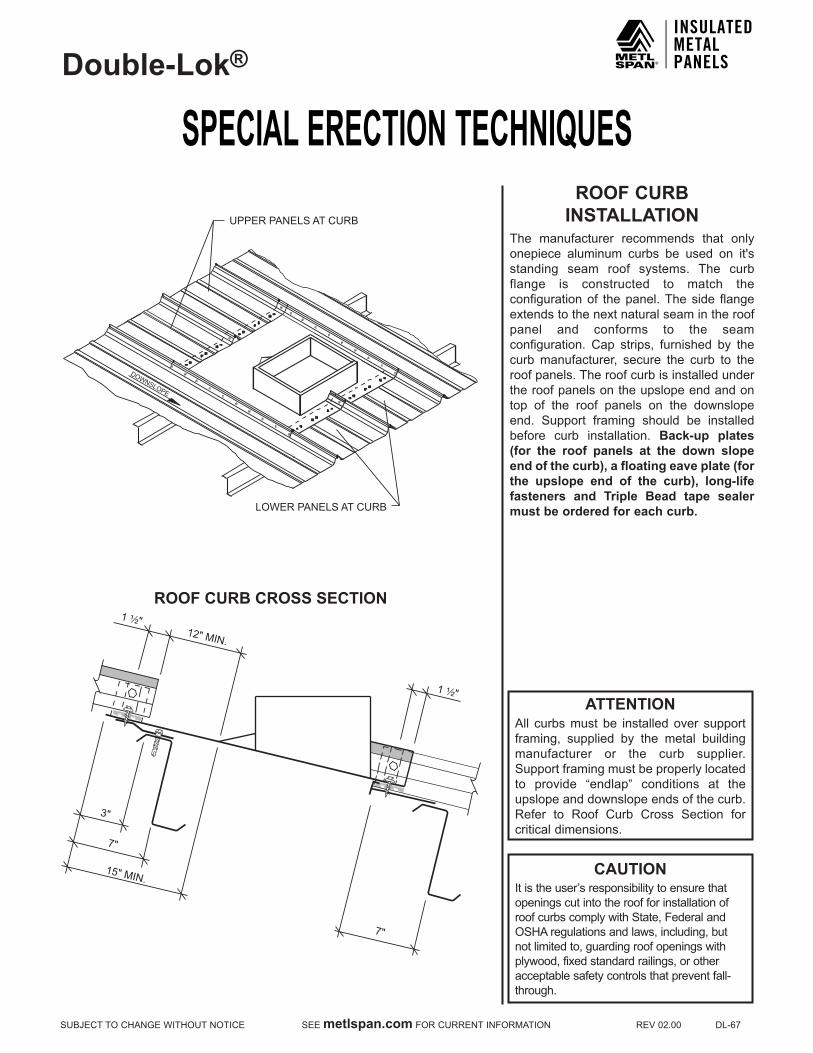
SPECIAL ERECTION TECHNIQUESDouble-Lok®
SUBJECTTOCHANGEWITHOUTNOTICESEEmetlspan.comFORCURRENTINFORMATIONREV02.00DL-67
ROOF CURB INSTALLATION
The manufacturer recommends that only onepiece aluminum curbs be used on it'sstanding seam roof systems. The curb flange is constructed to match the configuration of the panel. The side flange extendstothenextnaturalseamintheroofpanel and conforms to the seam configuration. Cap strips, furnished by thecurb manufacturer, secure the curb to the roof panels. The roof curb is installed under the roof panels on the upslope end and on top of the roof panels on the downslope end. Support framing should be installed before curb installation. Back-up plates (for the roof panels at the down slope end of the curb), a floating eave plate (for the upslope end of the curb), long-life fasteners and Triple Bead tape sealer must be ordered for each curb.
UPPER PANELS AT CURB
LOWER PANELS AT CURB
DOWNSLOPE
ROOF CURB CROSS SECTION
15" MIN.
7"
12" MIN.
1 ¹⁄₂"
1 ¹⁄₂"
3"
7"
ATTENTIONAll curbs must be installed over support framing, supplied by the metal building manufacturer or the curb supplier. Support framing must be properly located to provide “endlap” conditions at the upslope and downslope ends of the curb. Refer to Roof Curb Cross Section forcritical dimensions.
CAUTIONItistheuser’sresponsibilitytoensurethatopenings cut into the roof for installation of roof curbs comply with State, Federal and OSHA regulations and laws, including, but not limited to, guarding roof openings with plywood,fixedstandardrailings,orotheracceptable safety controls that prevent fall-through.

SPECIAL ERECTION TECHNIQUESDouble-Lok®
DL-68REV02.00SEEmetlspan.comFORCURRENTINFORMATIONSUBJECTTOCHANGEWITHOUTNOTICE
ROOF CURB INSTALLATION
(CONTINUED)Install curb support framing at curb location. Install full length roof panels up to curb location. Install lower panels at downslope end of curb. If the lower panels are field cut to length, you must (1) cut the downslope end, leaving a factory cut at the curb end or (2) if the curb end of the panel is field cut, notch the male leg as it is done in the factory. PlaceTripleBeadtape sealer across the full width of each panel as it is installed. To determine how far down on the panel to place the tape sealer, temporarily lay the curb in place and mark the down slope edge of the curb on the first panel. This will give you a reference point as to how far down slope to place the tape sealer. It is critical that the tape sealer be installed across each panel individually so that the tape sealer can be placed over the male leg. This will provide a seal in the panel seamwhen the next panel isinstalled. Install back-up plates onto each of the lower panels.
ATTENTIONAll curbs must be installed over support framing, supplied by the metal building manufacturer or the curb supplier. Support framing must be properly located to provide "endlap" conditions at theupslope and downslope ends of the curb. Refer to Roof Curb Cross Section forcritical dimensions.
CAUTIONItistheuser’sresponsibilitytoensurethatopenings cut into the roof for installation of roof curbs comply with State, Federal and OSHA regulations and laws, including, but not limited to, guarding roof openings with plywood,fixedstandardrailings,orotheracceptable safety controls that prevent fall-through.
FLOATING EAVE PLATELOW SYSTEM HW-7617HIGH SYSTEM HW-7655
TRIPLE BEAD TAPE SEALER
MALE LEG
DOWNSLOPE
LOWER PANELS AT CURB
PURLIN FRAMING MEMBER OR SECONDARY CURB SUPPORT FRAMING
FASTENER #5¹⁄₄"-14 x 1 ¹⁄₄"SHOULDER TEK® 2@ 12" O.C.
1 ¹⁄₂"

SPECIAL ERECTION TECHNIQUESDouble-Lok®
SUBJECTTOCHANGEWITHOUTNOTICESEEmetlspan.comFORCURRENTINFORMATIONREV02.00DL-69
CAUTIONItistheuser’sresponsibilitytoensurethatopenings cut into the roof for installation of roof curbs comply with State, Federal and OSHA regulations and laws, including, but not limited to, guarding roof openings with plywood,fixedstandardrailings,orotheracceptable safety controls that prevent fall-through.
ROOF CURB INSTALLATION
(CONTINUED)Install the roof curb on top of the lower roof panels and the curb support framing. Do not attach the curb to the support framing as this may prevent the curb from floating with the roof. Fasten the down slope end of the roof curb to the lower roof panels and back-up plateswithFastener #1Eas at a standardendlap.Thiswillrequiresixfastenersinthepan of the panel and one in each trapezoid for a total of eight fasteners per panel. FastenersmustgothroughtheTripleBeadtape sealer.
Install Triple Bead tape sealer across thewidth of the upslope end of the roof curb. Use the down slope end of the inside cap cell, which is welded to the roof curb, as a guide for placement of the tape sealer.
Apply minor rib tape sealer to the underside of the minor ribs on the down slope end of the upper panels. Install the upper panels withFastener#1Easatastandardendlap.Thiswill requiresix fasteners in thepanofthe panel and one in each trapezoid for a total of eight fasteners per panel. Fasteners mustgothroughtheTripleBeadtapesealer.The down slope edge of these panels should be flush with the down slope edge of the inside cap cell. Apply urethane sealant to the male leg of all panels directly over the inside cap cell. This will prevent water infiltration through the end of the panel seam.
DOWNSLOPE
FASTENER # 1E (6) PER PANEL FLOATING CURB
PURLIN
TRIPLE BEAD TAPE SEALER
BACK-UP PLATE
1'-0" MIN. TYP.
TRIPLE BEAD TAPE SEALER
LOWER PANELS AT CURB
MALE LEG OF PANEL
URETHANE SEALANT
INSIDE CAP CELL
TRIPLE BEAD TAPE SEALER
DIRECTION OF INSTALLATION
DOWNSLOPE
MINOR RIB TAPE SEALER
UPPER PANELS AT CURB
LOWER PANELS AT CURB
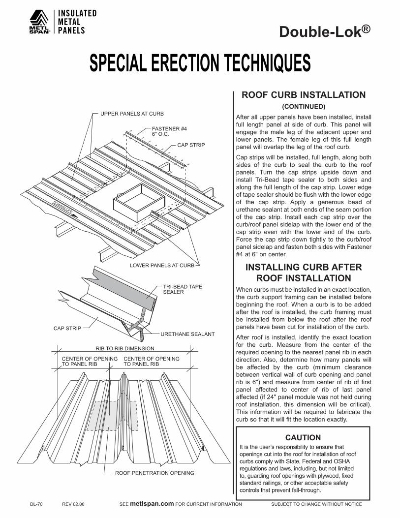
SPECIAL ERECTION TECHNIQUESDouble-Lok®
DL-70REV02.00SEEmetlspan.comFORCURRENTINFORMATIONSUBJECTTOCHANGEWITHOUTNOTICE
CAUTIONItistheuser’sresponsibilitytoensurethatopenings cut into the roof for installation of roof curbs comply with State, Federal and OSHA regulations and laws, including, but not limited to,guardingroofopeningswithplywood,fixedstandard railings, or other acceptable safety controls that prevent fall-through.
ROOF CURB INSTALLATION(CONTINUED)
After all upper panels have been installed, install full length panel at side of curb. This panel will engage the male leg of the adjacent upper and lower panels. The female leg of this full length panel will overlap the leg of the roof curb.
Capstripswillbeinstalled,fulllength,alongbothsides of the curb to seal the curb to the roof panels. Turn the cap strips upside down and install Tri-Bead tape sealer to both sides andalongthefulllengthofthecapstrip.Loweredgeof tape sealer should be flush with the lower edge of the cap strip. Apply a generous bead of urethane sealant at both ends of the seam portion of the cap strip. Install each cap strip over the curb/roof panel sidelap with the lower end of the cap strip even with the lower end of the curb. Force the cap strip down tightly to the curb/roof panel sidelap and fasten both sides with Fastener #4at6"oncenter.
INSTALLING CURB AFTER ROOF INSTALLATION
Whencurbsmustbeinstalledinanexactlocation,the curb support framing can be installed before beginning the roof.Whenacurb is tobeaddedafter the roof is installed, the curb framing must be installed from below the roof after the roof panels have been cut for installation of the curb.
After roof is installed, identify theexact locationfor the curb. Measure from the center of the required opening to the nearest panel rib in each direction. Also, determine how many panels will be affected by the curb (minimum clearancebetween vertical wall of curb opening and panel rib is6")andmeasure fromcenterof ribof firstpanel affected to center of rib of last panel affected(if24"panelmodulewasnotheldduringroof installation, this dimension will be critical).This information will be required to fabricate the curbsothatitwillfitthelocationexactly.
UPPER PANELS AT CURB
DOWNSLOPE
LOWER PANELS AT CURB
RIB TO RIB DIMENSION
CENTER OF OPENING TO PANEL RIB
CENTER OF OPENING TO PANEL RIB
ROOF PENETRATION OPENING
TRI-BEAD TAPESEALER
URETHANE SEALANTCAP STRIP
CAP STRIP
FASTENER #46" O.C.

SPECIAL ERECTION TECHNIQUESDouble-Lok®
SUBJECTTOCHANGEWITHOUTNOTICESEEmetlspan.comFORCURRENTINFORMATIONREV02.00DL-71
CAUTIONItistheuser’sresponsibilitytoensurethatopenings cut into the roof for installation of roof curbs comply with State, Federal and OSHA regulations and laws, including, but not limited to, guarding roof openings with plywood,fixedstandardrailings,orotheracceptable safety controls that prevent fall-through.
INSTALLING CURB AFTER ROOF INSTALLATION
(CONTINUED)Once curb is ready to be installed, lay curb on roof and align opening in the curb with theexactlocationtheopeningisrequiredinthe roof. At the up slope end of the roof curb, the roof panels will be cut on a line even with the beginning of the notch at the vertical leg on each side of the roof curb. Secondly, trace a line along the down slope edge of the roof curb. The roof panels will be cut on aline4"upslopefromthisline.
Cutroofpanelsfromriboffirstpanelaffectedby curb, to rib of last panel affected, along the top and bottom cut lines previously marked.
At the down slope end of the roof opening, install back-up plates onto the ends of the cutroofpanelsandTripleBeadtapesealeracross the full width of these roof panels. The down slope edge of the tape sealer should be on the line previously traced along the downslope edge of the roof curb. The up slope edge of the tape sealer will be approximately11/2"fromtheendofthecutpanel.
ApplyTripleBeadtapesealeracrossthefullwidth of the up slope end of the roof curb. The down slope edge of the tape sealer will align with the down slope edge of the inside cap cells welded to the roof curb.
Install the roof curb under the roof panels at the up slope end and on top of the panels at the down slope end. This will require that you lift the roof panels up slightly at the up slope end to allow the upper flange of the roof curb to slide under the panels. Spray some soapy water on the tape sealer to prevent it from sticking to the roof panels until you have the curb completely in place.
REQUIREDOPENING IN ROOF
MARK LINE AT CURB EDGE(FOR TRIPLE BEAD TAPESEALER PLACEMENT)
MARK LINE AT NOTCH IN CURB
DOWNSLOPE
UPPER PANELSAT CURB
LOWER PANELSAT CURB
PANEL CUT LINE
4"

SPECIAL ERECTION TECHNIQUESDouble-Lok®
DL-72REV02.00SEEmetlspan.comFORCURRENTINFORMATIONSUBJECTTOCHANGEWITHOUTNOTICE
INSTALLING CURB AFTER ROOF INSTALLATION
(CONTINUED)Capstripswillbeinstalled,fulllength,alongboth sides of the curb to seal the curb to the roof panels. Turn the cap strips upside down and install Tri-Bead tape sealer to bothsides and along the full length of the cap strip.Loweredgeof tapesealershouldbeflush with the lower edge of the cap strip. Apply a generous bead of urethane sealant at both ends of the seam portion of the cap strip. Install each cap strip over the curb/roof panel sidelap with the lower end of the cap strip even with the lower end of the curb. Force the cap strip down tightly to the curb/roof panel sidelap and fasten both sideswithFastener#4at6"oncenter.
CAUTIONItistheuser’sresponsibilitytoensurethatopenings cut into the roof for installation of roof curbs comply with State, Federal and OSHA regulations and laws, including, but not limited to, guarding roof openings with plywood,fixedstandardrailings,orotheracceptable safety controls that prevent fall-through.
UPPER PANELS AT CURB
DOWNSLOPE
LOWER PANELS AT CURB
RIB TO RIB DIMENSION
CENTER OF OPENING TO PANEL RIB
CENTER OF OPENING TO PANEL RIB
ROOF PENETRATION OPENING
TRI-BEAD TAPESEALER
URETHANE SEALANTCAP STRIP
CAP STRIP
FASTENER #46" O.C.
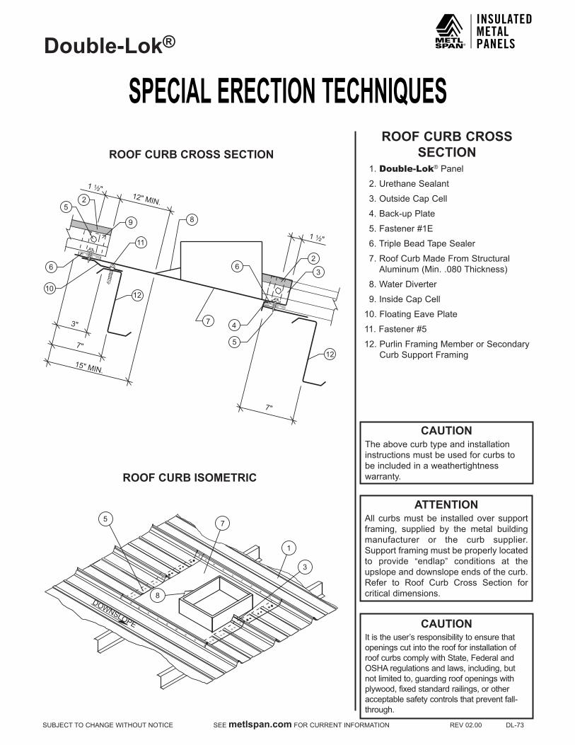
SPECIAL ERECTION TECHNIQUESDouble-Lok®
SUBJECTTOCHANGEWITHOUTNOTICESEEmetlspan.comFORCURRENTINFORMATIONREV02.00DL-73
CAUTIONItistheuser’sresponsibilitytoensurethatopenings cut into the roof for installation of roof curbs comply with State, Federal and OSHA regulations and laws, including, but not limited to, guarding roof openings with plywood,fixedstandardrailings,orotheracceptable safety controls that prevent fall-through.
ROOF CURB CROSS SECTION
1.Double-Lok® Panel
2.UrethaneSealant
3.OutsideCapCell
4.Back-upPlate
5.Fastener#1E
6.TripleBeadTapeSealer
7.RoofCurbMadeFromStructuralAluminum(Min..080Thickness)
8.WaterDiverter
9.InsideCapCell
10.FloatingEavePlate
11.Fastener#5
12.PurlinFramingMemberorSecondaryCurbSupportFraming
3
7
1
5
8 DOWNSLOPE
ROOF CURB ISOMETRIC
ROOF CURB CROSS SECTION
15" MIN.
7"
12" MIN.
1 ¹⁄₂"
1 ¹⁄₂"
3"
7"
8
7 4
3
2 5
6
5
10 12
11
9
12
2 6
ATTENTIONAll curbs must be installed over support framing, supplied by the metal building manufacturer or the curb supplier. Support framing must be properly located to provide “endlap” conditions at the upslope and downslope ends of the curb. Refer to Roof Curb Cross Section forcritical dimensions.
CAUTIONThe above curb type and installationinstructions must be used for curbs tobe included in a weathertightnesswarranty.
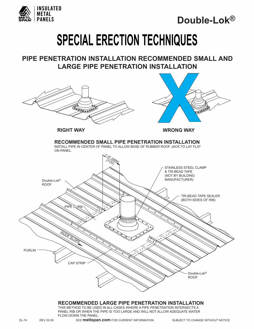
SPECIAL ERECTION TECHNIQUESDouble-Lok®
DL-74REV02.00SEEmetlspan.comFORCURRENTINFORMATIONSUBJECTTOCHANGEWITHOUTNOTICE
PIPE PENETRATION INSTALLATION RECOMMENDED SMALL AND LARGE PIPE PENETRATION INSTALLATION
WRONG WAY RIGHT WAY
RECOMMENDED SMALL PIPE PENETRATION INSTALLATION INSTALL PIPE IN CENTER OF PANEL TO ALLOW BASE OF RUBBER ROOF JACK TO LAY FLAT ON PANEL.
TRI-BEAD TAPE SEALER (BOTH SIDES OF RIB)
CAP STRIP
PIPE CURB
PURLIN
RECOMMENDED LARGE PIPE PENETRATION INSTALLATION THIS METHOD TO BE USED IN ALL CASES WHERE A PIPE PENETRATION INTERSECTS A PANEL RIB OR WHEN THE PIPE IS TOO LARGE AND WILL NOT ALLOW ADEQUATE WATER FLOW DOWN THE PANEL.
STAINLESS STEEL CLAMP & TRI-BEAD TAPE (NOT BY BUILDING MANUFACTURER)
Double-Lok®
ROOF
Double-Lok®
ROOF
1'-0" (MIN) (TYP)
ROOF SLOPE

SPECIAL ERECTION TECHNIQUESDouble-Lok®
SUBJECTTOCHANGEWITHOUTNOTICESEEmetlspan.comFORCURRENTINFORMATIONREV02.00DL-75
PIPE PENETRATION INSTALLATIONDECk-TIGHT INSTALLATION
STEP 2
¹⁄₄"-14 x ⁷⁄₈" LONG LIFE LAP TEK®
S.D. w/WASHER (FASTENER #4)@ 1" O.C.
STEP 1
STAINLESS STEEL CLAMP (NOT BY BUILDING MANUFACTURER)
TRI-BEAD TAPE SEALER (HW-504)
DECK-TIGHT (NOT BY BUILDING MANUFACTURER) ROLL TOP OF DECK-TIGHT DOWN
DECK-TIGHT (NOT BY MANUFACTURER)
STAINLESS STEEL CLAMP (NOT BY BUILDING MANUFACTURER)
TRI-BEAD TAPE SEALER (HW-504)
APPLY TRI-BEAD TAPE SEALER CONTINUOUSLY AROUND PIPE (HW-504)
¹⁄₄"-14 x ⁷⁄₈" LONG LIFE LAP TEK®
S.D. w/WASHER (FASTENER #4)@ 1" O.C.
NOTE: ROLL DECK-TIGHT UP OVER TRI-BEAD TAPE SEALER AND SECURE CLAMP AROUND TOP OF DECK-TIGHT
STEP 3
TRI-BEAD TAPE SEALER (HW-504) STAINLESS STEEL CLAMP
(NOT BY BUILDING MANUFACTURER)
TRI-BEAD TAPE SEALER (HW-504)
DECK-TIGHT (NOT BY MANUFACTURER)
¹⁄₄"-14 x ⁷⁄₈" LONG LIFE LAP TEK®
S.D. w/WASHER (FASTENER #4)@ 1" O.C.

SPECIAL ERECTION TECHNIQUESDouble-Lok®
DL-76REV02.00SEEmetlspan.comFORCURRENTINFORMATIONSUBJECTTOCHANGEWITHOUTNOTICE
Double-Lok® REPAIR CAP INSTALLATION
1. Repair cap must extend 1'-0" above and below the damaged area.2. ³⁄₁₆" x ¹³⁄₁₆" closed end rivet fastened through each clip and both sides of panel rib in damaged area. (2 required per clip)
PRE-DRILL HOLE THROUGH CLIP AND BOTH SIDES OF PANEL SEAM
³⁄₁₆" x ¹³⁄₁₆" CLOSED END RIVET (FASTENER #227) (2) PER CLIP
FLOATING CLIP
FLOATING CLIP
1'-0" MIN.
1'-0" MIN.
DAMAGED SEAM
ROOF SLOPE
STEP 1
Double-Lok®
ROOF
CAP STRIP
URETHANE SEALANT
CAP STRIP
¹⁄₄"-14 x ⁷⁄₈" LONG LIFE LAP TEK®
SDS WITH WASHER (6" O.C.) (FASTENERS #4)(FASTENERS MUST GO THROUGH TAPE SEALANT)
TRI-BEAD TAPE SEALER(BOTH SIDES OF RIB)
1'-0" MIN.
1'-0" MIN.
DAMAGED SEAM
ROOF SLOPE
1. Install a continuous run of Tri-Bead tape sealer to both sides of damaged panel rib.2. Apply a bead of urethane sealant up and over both panel ribs at each end of damaged panel seam.3. Fill seam portion of repair cap with urethane sealant.4. Push repair cap down onto panel rib and fasten with ¹⁄₄"-14 x ⁷⁄₈" Long Life Lap Tek® (Fastener #4) @ 6" O.C. on both sides. Fasteners must go through tape sealer.5. Check repair cap at each end to verify that urethane sealant has sealed across the entire cross section of repair cap.
STEP 2
Double-Lok®
ROOF

SPECIAL ERECTION TECHNIQUESDouble-Lok®
SUBJECTTOCHANGEWITHOUTNOTICESEEmetlspan.comFORCURRENTINFORMATIONREV02.00DL-77
S-5!™ Double-Lok® WIND CLAMPINSTALLATION LOCATION
PURLIN
ROOF PANEL CLIP
SECTION A-A
S-5!™ Double-Lok® WIND CLAMP(HW-569)
SECTION B-B
S-5!™ Double-Lok® WIND CLAMP(HW-569)
PURLIN
ROOF PANEL CLIP
Double-Lok®
ROOF PANEL
PURLIN
ROOF PANEL CLIP
S-5!™ Double-Lok® WIND CLAMP(HW-569) (CLAMP MUSTBE TORQUED TO 140 in. lbs.)
Double-Lok®
ROOF PANEL
Double-Lok®
ROOF PANEL
NOTES:1.OnlyforusewithHW-2122,2124,2126,and2128clips.2.Torquesetscrewto140in-lbs.3.Application zone and feasibility of wind clamps must be determined by a Registered Professional Engineer.4.Forloadtablespleaseinquire.
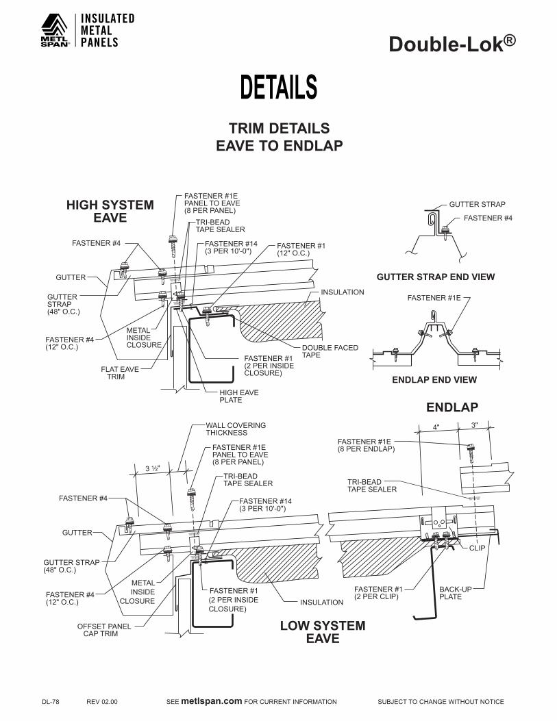
DETAILSDouble-Lok®
DL-78REV02.00SEEmetlspan.comFORCURRENTINFORMATIONSUBJECTTOCHANGEWITHOUTNOTICE
TRIM DETAILSEAVE TO ENDLAP
FASTENER #1EPANEL TO EAVE(8 PER PANEL)
FASTENER #4
METALINSIDECLOSURE
GUTTER
INSULATION
FASTENER #1(2 PER INSIDECLOSURE)
FASTENER #1(12" O.C.)
FASTENER #4(12" O.C.)
TRI-BEADTAPE SEALER
GUTTERSTRAP(48" O.C.)
HIGH SYSTEMEAVE
HIGH EAVEPLATE
DOUBLE FACEDTAPE
FLAT EAVE TRIM
FASTENER #1E
ENDLAP END VIEW
GUTTER STRAP END VIEW
FASTENER #4
GUTTER STRAP
FASTENER #14(3 PER 10'-0")
3 ¹⁄₂"
WALL COVERINGTHICKNESS
FASTENER #1EPANEL TO EAVE(8 PER PANEL)
GUTTER STRAP(48" O.C.)
FASTENER #4
METALINSIDE
CLOSURE
GUTTER
OFFSET PANEL CAP TRIM
INSULATIONFASTENER #1(2 PER INSIDECLOSURE)
4" 3"
FASTENER #1(2 PER CLIP)
CLIP
BACK-UPPLATE
FASTENER #1E(8 PER ENDLAP)
LOW SYSTEMEAVE
ENDLAP
FASTENER #4(12" O.C.)
TRI-BEADTAPE SEALER
TRI-BEADTAPE SEALER
FASTENER #14(3 PER 10'-0")
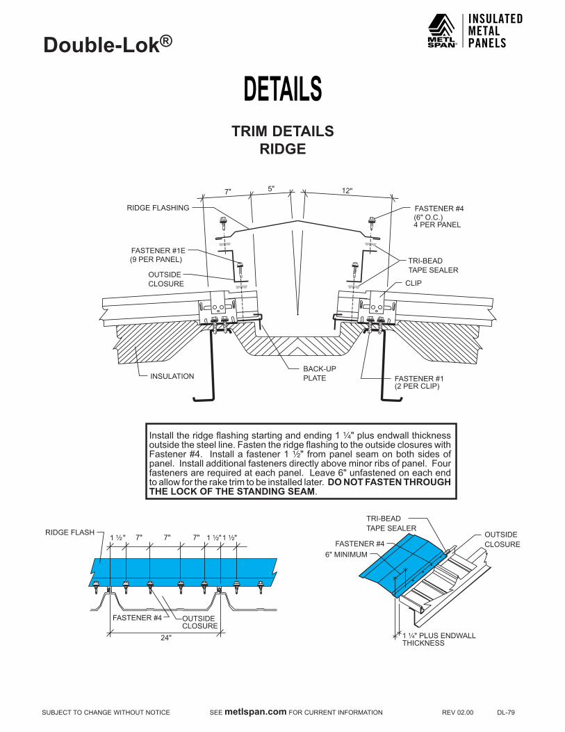
DETAILSDouble-Lok®
SUBJECTTOCHANGEWITHOUTNOTICESEEmetlspan.comFORCURRENTINFORMATIONREV02.00DL-79
TRIM DETAILSRIDGE
OUTSIDECLOSURE
FASTENER #4
1 ¹⁄₂"1 ¹⁄₂"RIDGE FLASH
1 ¹⁄₂ " 7" 7" 7"
24"
TRI-BEADTAPE SEALER
FASTENER #1(2 PER CLIP)
BACK-UPPLATE
FASTENER #4(6" O.C.)4 PER PANEL
12"
CLIP
INSULATION
OUTSIDECLOSURE
FASTENER #1E(9 PER PANEL)
RIDGE FLASHING
5"7"
6" MINIMUM
TRI-BEADTAPE SEALER
FASTENER #4OUTSIDECLOSURE
1 ¹⁄₄" PLUS ENDWALLTHICKNESS
Install the ridge flashing starting and ending 1 ¹⁄₄" plus endwall thickness outside the steel line. Fasten the ridge flashing to the outside closures with Fastener #4. Install a fastener 1 ¹⁄₂" from panel seam on both sides of panel. Install additional fasteners directly above minor ribs of panel. Four fasteners are required at each panel. Leave 6" unfastened on each end to allow for the rake trim to be installed later. DO NOT FASTEN THROUGH THE LOCK OF THE STANDING SEAM.
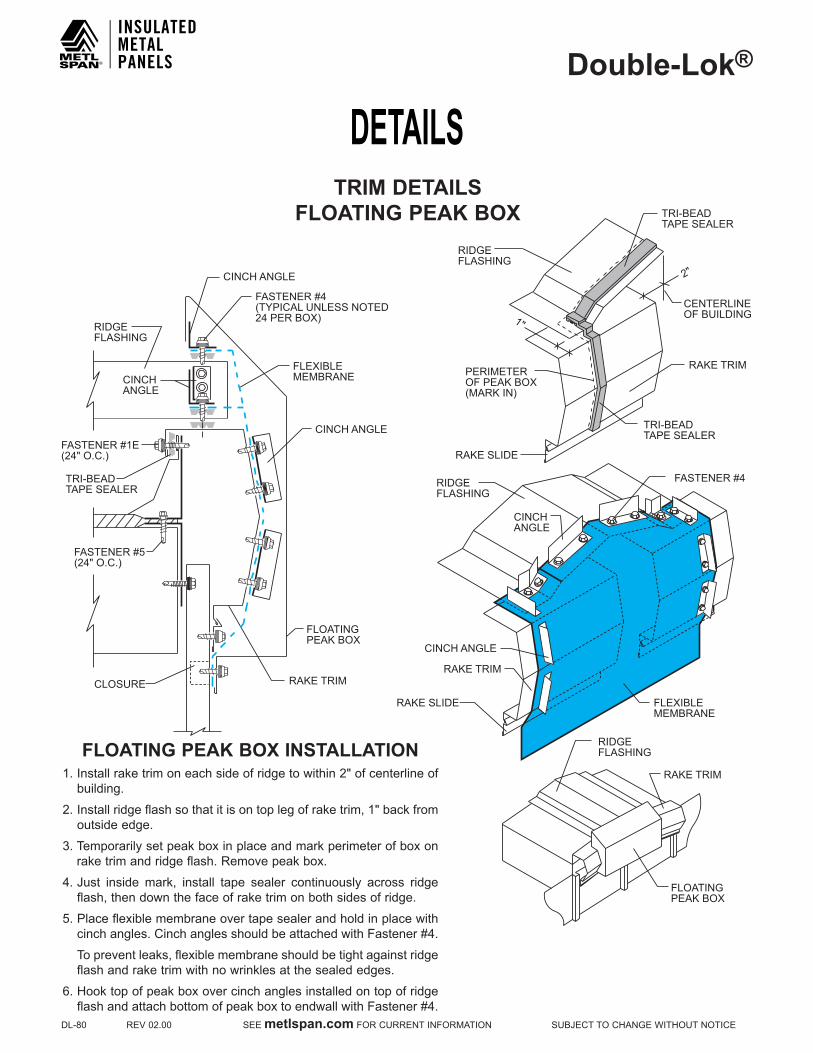
DETAILSDouble-Lok®
DL-80REV02.00SEEmetlspan.comFORCURRENTINFORMATIONSUBJECTTOCHANGEWITHOUTNOTICE
TRIM DETAILSFLOATING PEAk BOX
FLOATING PEAk BOX INSTALLATION1.Installraketrimoneachsideofridgetowithin2"ofcenterlineof
building.
2.Installridgeflashsothatitisontoplegofraketrim,1"backfromoutside edge.
3.Temporarilysetpeakboxinplaceandmarkperimeterofboxonraketrimandridgeflash.Removepeakbox.
4.Just inside mark, install tape sealer continuously across ridgeflash, then down the face of rake trim on both sides of ridge.
5.Placeflexiblemembraneovertapesealerandholdinplacewithcinchangles.CinchanglesshouldbeattachedwithFastener#4.
Topreventleaks,flexiblemembraneshouldbetightagainstridgeflash and rake trim with no wrinkles at the sealed edges.
6.HooktopofpeakboxovercinchanglesinstalledontopofridgeflashandattachbottomofpeakboxtoendwallwithFastener#4.
CINCH ANGLE
CINCH ANGLE
FASTENER #4(TYPICAL UNLESS NOTED24 PER BOX)
FLEXIBLEMEMBRANE
FASTENER #1E(24" O.C.)
CLOSURE
CINCHANGLE
RIDGEFLASHING
FLOATING PEAK BOX
RAKE TRIM RAKE TRIM
RIDGEFLASHING
RAKE TRIM
CINCHANGLE
RIDGEFLASHING
TRI-BEADTAPE SEALER
PERIMETEROF PEAK BOX(MARK IN)
RAKE SLIDE
RAKE SLIDE
CINCH ANGLE
FLEXIBLEMEMBRANE
FASTENER #4
CENTERLINEOF BUILDING
RAKE TRIM
RIDGEFLASHING
FLOATINGPEAK BOX
2"
1"
TRI-BEADTAPE SEALER
TRI-BEADTAPE SEALER
FASTENER #5(24" O.C.)
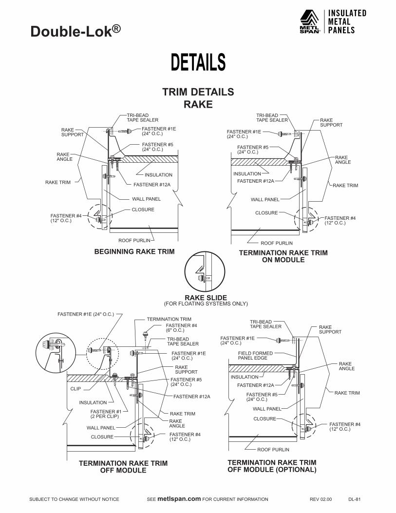
DETAILSDouble-Lok®
SUBJECTTOCHANGEWITHOUTNOTICESEEmetlspan.comFORCURRENTINFORMATIONREV02.00DL-81
TRIM DETAILSRAkE
FASTENER #5(24" O.C.)
FASTENER #4(12" O.C.)
FASTENER #1E(24" O.C.)
INSULATION
RAKESUPPORT
RAKEANGLE
CLOSURE
WALL PANEL
RAKE TRIM
TRI-BEADTAPE SEALER
ROOF PURLIN
FASTENER #5(24" O.C.)
FASTENER #4(12" O.C.)
FASTENER #1E(24" O.C.)
INSULATION
RAKESUPPORT
RAKEANGLE
CLOSURE
WALL PANEL
RAKE TRIM
TRI-BEADTAPE SEALER
ROOF PURLIN
FIELD FORMEDPANEL EDGE
FASTENER #5(24" O.C.)
FASTENER #4(12" O.C.)
FASTENER #1E(24" O.C.)
INSULATION
RAKESUPPORT
RAKEANGLE
CLOSURE
WALL PANEL
RAKE TRIM
TRI-BEADTAPE SEALER
ROOF PURLIN
TERMINATION TRIMFASTENER #4(6" O.C.)
FASTENER #5(24" O.C.)
FASTENER #4(12" O.C.)
FASTENER #1(2 PER CLIP)
FASTENER #1E(24" O.C.)
FASTENER #1E (24" O.C.)
INSULATION
CLIP
RAKESUPPORT
RAKEANGLE
CLOSURE
WALL PANEL
RAKE TRIM
TRI-BEADTAPE SEALER
RAKE SLIDE(FOR FLOATING SYSTEMS ONLY)
BEGINNING RAKE TRIM TERMINATION RAKE TRIMON MODULE
TERMINATION RAKE TRIMOFF MODULE
TERMINATION RAKE TRIMOFF MODULE (OPTIONAL)
FASTENER #12A
FASTENER #12A
FASTENER #12A
FASTENER #12A

DETAILSDouble-Lok®
DL-82REV02.00SEEmetlspan.comFORCURRENTINFORMATIONSUBJECTTOCHANGEWITHOUTNOTICE
TRIM DETAILSRAkE TO RAkE
NOTES:For an adequate understanding of how to design the Double-Lok® roof system, it is important to read the section of this manual which includes all trim details.
BEGINNING- ALL BUILDINGS
FEMALE LIP
24" or 18" 24" or 18" MALE LEGSTEEL LINE
RAKE SUPPORT
RAKESLIDE
12"
TERMINATION - ODD FOOTAGE BUILDINGS
FIELD CUT PANEL RAKE
SUPPORT
24" or 18"
24" or 18" TERMINATIONTRIM
TERMINATION - BUILDINGS OFF MODULEA TERMINATION TRIM IS PROVIDED FOR THIS CONDITION
TERMINATION - EVEN FOOTAGE BUILDINGS
24" or 18" 24" or 18"
RAKETRIM
STEELLINE
RAKESLIDE (FORFLOATINGSYSTEMSONLY)
RAKE SUPPORT

DETAILSDouble-Lok®
SUBJECTTOCHANGEWITHOUTNOTICESEEmetlspan.comFORCURRENTINFORMATIONREV02.00DL-83
TRIM DETAILSRAkE PARAPET
URETHANE SEALANT
ALTERNATECOUNTERFLASH
FASTENER #1E
PURLIN
FASTENER #11
URETHANE SEALANTCOUNTERFLASH
PARAPET RAKEFLASH
TRI-BEADTAPE SEALER
RAKE SUPPORTANGLE
PARAPETWALL
PARAPETRAKE CLEAT
BEGINNINGON MODULE
FINISHINGOFF MODULE
FASTENER #11
TRI-BEADTAPE SEALER
FASTENER #1E(24" O.C.)
FASTENER #5(24" O.C.)
RAKE ANGLE
FASTENER #11
BEGINNINGPARAPET RAKE
TERMINATIONPARAPET RAKE
2" MINIMUM2" MINIMUM
Double-Lok®
PANELFASTENER #12A
FASTENER #12A
FASTENER #5(24" O.C.)
URETHANE SEALANT
COUNTERFLASH
FASTENER #1E(24" O.C.)
PURLIN
FINISHINGOFF MODULE
FASTENER
TRI-BEAD TAPE SEALER
TERMINATIONPARAPET RAKE (Optional)
PARAPETRAKE CLEAT
RAKE ANGLE
RAKE SUPPORTANGLE
PARAPET RAKEFLASH
2" MINIMUMDouble-Lok®
PANEL
FASTENER #12A
DETAIL A(Optional)
Use in areas that experiencesnow loads greater than 10PSF.
Double-Lok®
PANEL
FASTENER
FASTENER
FASTENER #1E@ 12" O.C.
URETHANE SEALANT
TAPE SEALER
COUNTER FLASHING
PARAPETRAKE CLEAT
TAPE SEALER
PARAPET RAKE FLASHING
RAKEANGLE
FASTENER #5@ 24" O.C.
2" MIN.
FLEXIBLEMEMBRANE(EPDM)
RAKE ANGLESUPPORT
URETHANE SEALANT
ALTERNATECOUNTERFLASH
FASTENER #1E
PURLIN
FASTENER #11
URETHANE SEALANTCOUNTERFLASH
PARAPET RAKEFLASH
TRI-BEADTAPE SEALER
RAKE SUPPORTANGLE
PARAPETWALL
PARAPETRAKE CLEAT
BEGINNINGON MODULE
FINISHINGOFF MODULE
FASTENER #11
TRI-BEADTAPE SEALER
FASTENER #1E(24" O.C.)
FASTENER #5(24" O.C.)
RAKE ANGLE
FASTENER #11
BEGINNINGPARAPET RAKE
TERMINATIONPARAPET RAKE
2" MINIMUM2" MINIMUM
Double-Lok®
PANELFASTENER #12A
FASTENER #12A
FASTENER #5(24" O.C.)
URETHANE SEALANT
COUNTERFLASH
FASTENER #1E(24" O.C.)
PURLIN
FINISHINGOFF MODULE
FASTENER
TRI-BEAD TAPE SEALER
TERMINATIONPARAPET RAKE (Optional)
PARAPETRAKE CLEAT
RAKE ANGLE
RAKE SUPPORTANGLE
PARAPET RAKEFLASH
2" MINIMUMDouble-Lok®
PANEL
FASTENER #12A
DETAIL A(Optional)
Use in areas that experiencesnow loads greater than 10PSF.
Double-Lok®
PANEL
FASTENER
FASTENER
FASTENER #1E@ 12" O.C.
URETHANE SEALANT
TAPE SEALER
COUNTER FLASHING
PARAPETRAKE CLEAT
TAPE SEALER
PARAPET RAKE FLASHING
RAKEANGLE
FASTENER #5@ 24" O.C.
2" MIN.
FLEXIBLEMEMBRANE(EPDM)
RAKE ANGLESUPPORT

DETAILSDouble-Lok®
DL-84REV02.00SEEmetlspan.comFORCURRENTINFORMATIONSUBJECTTOCHANGEWITHOUTNOTICE
TRIM DETAILSHIGH EAVE PARAPET
NOTES:HIGH SIDE PURLIN IS 9" DOWN SLOPE
7" 2"
FASTENER #1(2 REQUIRED)
CLIP
BACK-UP PLATE
FASTENER #1E(6 PER PANEL)
TRI-BEAD TAPE SEALER
URETHANE SEALANT
COUNTER FLASH
PARAPET HIGH SIDE FLASHING
FASTENER #4 (6" O.C.)4 PER PANEL
TRI-BEADTAPE SEALER
FASTENER #11 (24" O.C.)
FASTENER #1E(3 PER PANEL)
PURLIN
Double-Lok®
PANEL
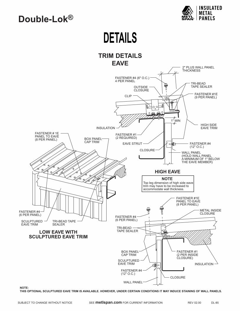
DETAILSDouble-Lok®
SUBJECTTOCHANGEWITHOUTNOTICESEEmetlspan.comFORCURRENTINFORMATIONREV02.00DL-85
TRIM DETAILSEAVE
NOTE:THIS OPTIONAL SCULPTURED EAVE TRIM IS AVAILABLE. HOWEVER, UNDER CERTAIN CONDITIONS IT MAY INDUCE STAINING OF WALL PANELS.
TRI-BEADTAPE SEALEROUTSIDE
CLOSURE
EAVE STRUT
INSULATION
FASTENER #1E(9 PER PANEL)
CLOSURE
HIGH SIDE EAVE TRIM
FASTENER #4 (6" O.C.)4 PER PANEL
WALL PANEL(HOLD WALL PANELA MINIMUM OF 1" BELOWTHE EAVE MEMBER)
FASTENER #1(2 REQUIRED)
FASTENER #4(12" O.C.)
CLIP
2" PLUS WALL PANELTHICKNESS
1" MIN
FASTENER # 1EPANEL TO EAVE(8 PER PANEL)
FASTENER #4(6 PER PANEL)
SCULPTURED EAVE TRIM
BOX PANELCAP TRIM
TRI-BEAD TAPESEALER
TRI-BEADTAPE SEALER
FASTENER #4(6 PER PANEL)
METAL INSIDECLOSURE
INSULATION
CLOSURE
SCULPTURED EAVE TRIM
FASTENER #4(12" O.C.)
WALL PANEL
FASTENER #1(2 PER INSIDECLOSURE)
FASTENER #1EPANEL TO EAVE(8 PER PANEL)
BOX PANELCAP TRIM
LOW EAVE WITHSCULPTURED EAVE TRIM
HIGH EAVE
Top leg dimension of high side eavetrim may have to be increased to accommodate wall thickness.
NOTE

DETAILSDouble-Lok®
DL-86REV02.00SEEmetlspan.comFORCURRENTINFORMATIONSUBJECTTOCHANGEWITHOUTNOTICE
TRIM DETAILSSNOW GUTTER
NOTES:1.AttachguttertoeaveplatewithFastener#14A(3fastenersper10'piece).2.Installgutterstraps3'-0"o.c.3.ApplyTri-Beadtapesealertoslopelegofgutter.4.UseminorribtapesealertofillvoidsinpanelatminorribsasshownonpageDL-36.5.InstallpanelwithFastener#1Eatprepunchedholes.Panel must not overhang into gutter.6.Fronttopedgeofguttermustnotprojectabovetheplaneofthepanelpan.
WALL PANEL
FASTENER #14A(3 PER 10'-0")
TRI-BEADTAPE SEALER
METAL INSIDECLOSURE
FASTENER #1EPANEL TO EAVE STRUTAND INSIDE CLOSURE(8 PER PANEL)
FASTENER #1(2 PER INSIDECLOSURE)
Double-Lok®
PANEL
GUTTER STRAP(3'-0" O.C.)
SNOWGUTTER
FASTENER #14
LOW SYSTEM
INSULATION
EAVE STRUT
DOUBLE FACED TAPE
¹⁄₂"
INSULATION
WALL PANEL
FASTENER #1(12" O.C.)
HIGH EAVEPLATE
EAVE STRUT
FASTENER #14A(3 PER 10'-0")
DOUBLE FACED TAPE
HIGH SYSTEM
TRI-BEADTAPE SEALER
METAL INSIDECLOSURE
FASTENER #1EPANEL TO EAVE STRUTAND INSIDE CLOSURE(8 PER PANEL)
FASTENER #1(2 PER INSIDECLOSURE)
Double-Lok®
PANELGUTTER STRAP(3'-0" O.C.)
SNOWGUTTER
FASTENER #14

DETAILSDouble-Lok®
SUBJECTTOCHANGEWITHOUTNOTICESEEmetlspan.comFORCURRENTINFORMATIONREV02.00DL-87
TRIM DETAILSFLOATING HIP
CAUTIONAlltrapezoidalpanelsareextremelydifficulttoinstallathipsandvalleysinaweathertightmanner.Theuseofthesedetailsshouldonlybeattemptedbyinstallationcrewsthatarehighlyexperienced.Inordertoassureweathertightness,Metl-Spanrecommendsoneofit’sverticallegstandingseamsystemsforuseonroofsthatrequirehipsandvalleys.
FLOATINGRIDGE/HIP FLASH
TRI-BEADTAPE SEALER
HIP SUPPORT PLATE (P-141)(FIELD NOTCH @ PURLINS)
FASTENER #14A
PURLIN
URETHANE SEALANT
ZEE CLOSURE(FIELD CUT TO LENGTHAND BEVEL CUT TO FIT PANEL)
3" x 3" x 16 GA. ANGLE
FASTENER #4(6" O.C.)
FASTENER #12ATWO PER PURLIN
Double-Lok®
PANEL
URETHANE SEALANT
TRI-BEADTAPE SEALER
FLOATING RIDGE/HIPFLASHING
HIP
ZEE CLOSURE(FIELD CUT TO LENGTH AND BEVELCUT TO FIT PANEL)
HIP SUPPORT PLATE (P-141)(FIELD NOTCH @ PURLINS)
3" x 3" x 16 GA.BACK-UP ANGLE
FASTENER #1
FASTENER #4(6" O.C.)
LOW FLOATING CLIP
FASTENER #14A(4" O.C. MAX.)
5"
FASTENER #12ATWO PER PURLIN
PURLIN
Double-Lok®
PANEL
2"
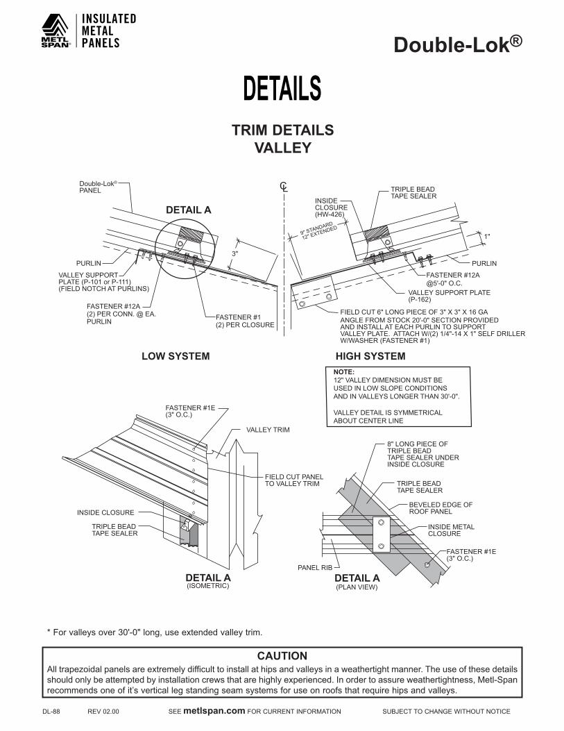
DETAILSDouble-Lok®
DL-88REV02.00SEEmetlspan.comFORCURRENTINFORMATIONSUBJECTTOCHANGEWITHOUTNOTICE
TRIM DETAILSVALLEY
CAUTIONAlltrapezoidalpanelsareextremelydifficulttoinstallathipsandvalleysinaweathertightmanner.Theuseofthesedetailsshouldonlybeattemptedbyinstallationcrewsthatarehighlyexperienced.Inordertoassureweathertightness,Metl-Spanrecommendsoneofit’sverticallegstandingseamsystemsforuseonroofsthatrequirehipsandvalleys.
*Forvalleysover30'-0"long,useextendedvalleytrim.
PANEL RIB
8" LONG PIECE OFTRIPLE BEAD TAPE SEALER UNDERINSIDE CLOSURE
TRIPLE BEADTAPE SEALER
BEVELED EDGE OFROOF PANEL
INSIDE METAL CLOSURE
FASTENER #1E(3" O.C.)
DETAIL A(PLAN VIEW)
TRIPLE BEADTAPE SEALER
INSIDE CLOSURE
FIELD CUT PANELTO VALLEY TRIM
VALLEY TRIM
DETAIL A(ISOMETRIC)
DETAIL A
FASTENER #1E(3" O.C.)
NOTE: 12" VALLEY DIMENSION MUST BEUSED IN LOW SLOPE CONDITIONSAND IN VALLEYS LONGER THAN 30'-0".
VALLEY DETAIL IS SYMMETRICALABOUT CENTER LINE
Double-Lok® PANEL
1"
VALLEY SUPPORT PLATE(P-162)
FASTENER #12A@5'-0" O.C.
LOW SYSTEM HIGH SYSTEM
PURLIN
TRIPLE BEADTAPE SEALER
INSIDECLOSURE(HW-426)
9" STANDARD
12" EXTENDED
3"
C L
VALLEY SUPPORTPLATE (P-101 or P-111)(FIELD NOTCH AT PURLINS)
PURLIN
FASTENER #12A(2) PER CONN. @ EA.PURLIN FASTENER #1
(2) PER CLOSURE
FIELD CUT 6" LONG PIECE OF 3" X 3" X 16 GA ANGLE FROM STOCK 20'-0" SECTION PROVIDED AND INSTALL AT EACH PURLIN TO SUPPORT VALLEY PLATE. ATTACH W/(2) 1/4"-14 X 1" SELF DRILLER W/WASHER (FASTENER #1)
NOTESDouble-Lok®
SUBJECTTOCHANGEWITHOUTNOTICESEEmetlspan.comFORCURRENTINFORMATIONREV02.00DL-89

NOTESDouble-Lok®
DL-90REV02.00SEEmetlspan.comFORCURRENTINFORMATIONSUBJECTTOCHANGEWITHOUTNOTICE

NOTESDouble-Lok®
SUBJECTTOCHANGEWITHOUTNOTICESEEmetlspan.comFORCURRENTINFORMATIONREV02.00DL-91
1720 lakepointe Drive suite #101 lewisville, Texas 75057
Toll-free: 877.585.9969 | email: [email protected] Web: metlspan.com
© 2019 Metl-Span, part of the Cornerstone Building Brands family. All Rights Reserved. Printed in the U.S.A. | January 31, 2019 / Rev 01.01