Double Diamond MMU Operating Manual - Peek Trafficpeektraffic.com/manuals/Double Diamond Operating...
158
Operating Manual Double Diamond Malfunction Management Unit NEMA TS 2 Compatible ®
Transcript of Double Diamond MMU Operating Manual - Peek Trafficpeektraffic.com/manuals/Double Diamond Operating...
Operating Manual
Double DiamondMalfunction Management Unit
NEMA TS 2 Compatible
®

Operating Manual
Double Diamond MMU™ NEMA-Compatible Malfunction Management Unit
1/7/2009 p/n: 8313A Rev 5

manual assembly: 8314B manual content: 8313A manual cover art: 99-344
Copyright © 2005 Peek Traffic Corporation. All rights reserved. Information furnished by Peek Traffic Corporation is believed to be accurate and reliable, however Peek does not warranty the accuracy, completeness, or fitness for use of any of the information furnished. No license is granted by implication or otherwise under any intellectual property. Peek reserves the right to alter any of the Company's products or published technical data relating thereto at any time without notice. No part of this publication may be reproduced, stored in a retrieval system, or transmitted in any form or via any electronic or mechanical means for any purpose other than the purchaser’s personal use without the expressed, written permission of Peek Traffic Corporation. Peek Traffic Corporation 2906 Corporate Way Palmetto, FL 34221 U.S.A. Trademarks Double Diamond MMU and 3000E Series Traffic Controllers are trademarks or registered trademarks of Peek Traffic Corporation, in the USA and other countries. Microsoft and Windows are trademarks or registered trademarks of Microsoft Corporation. Idris,™ Idris Technology,™ and the Idris logo are registered trademarks of Diamond Consulting Services, Ltd. Other brands and their products are trademarks or registered trademarks of their respective holders and should be noted as such.
Double Diamond MMU Operating Manual iii
Contents
Preface — About This Manual................................................................................... 1
Purpose and Scope ................................................................................................................................. 1 Assumptions ............................................................................................................................................ 1 Related Documents ................................................................................................................................. 2 Technical Assistance............................................................................................................................... 2
Chapter 1 — Introduction to the Double Diamond MMU ........................................ 3 Overview.................................................................................................................................................. 4
General Description of an MMU........................................................................................................ 4 Double Diamond MMU Operational Modes............................................................................................. 5
TS 2 Backward Compatibility ............................................................................................................ 5 Additional Features Available in TS 2 Mode ..................................................................................... 5
Other Advanced Features of the DD MMU.............................................................................................. 7 Monitoring Modes .................................................................................................................................... 9 Quick Set-Up Instructions...................................................................................................................... 11
Installation Notes............................................................................................................................. 11 General Guidelines During Setup ................................................................................................... 12 Configuring Global Settings ............................................................................................................ 12 Configuring Channel by Channel Settings ...................................................................................... 14
Chapter 2 — Double Diamond Hardware ............................................................... 17 Overview................................................................................................................................................ 18 Front Panel Controls and Indicators ...................................................................................................... 19
LCD Display .................................................................................................................................... 19 Keypad ............................................................................................................................................ 20 TS 2 Programming Card Slot .......................................................................................................... 21 TS 1 Programming Card Slot .......................................................................................................... 21 LED Status Indicators ..................................................................................................................... 22 Reset Button ................................................................................................................................... 23 Fuse ................................................................................................................................................ 23 Port 1............................................................................................................................................... 23 RS-232 Port .................................................................................................................................... 24 Connector A .................................................................................................................................... 24 Connector B .................................................................................................................................... 24
Programming Cards .............................................................................................................................. 25 TS 1 Programming Card ................................................................................................................. 25 TS 2 Programming Card ................................................................................................................. 26
Contents
iv Double Diamond MMU Operating Manual
Compatible Channel Programming .................................................................................................27 Ped Jumpers in Type 16 Mode ....................................................................................................... 29 Compatibility Jumper Cautionary Notes..........................................................................................29
Port 1 General Operation....................................................................................................................... 30 Frame Types ................................................................................................................................... 31
Configuring the Unit for ELRA/ELRB/LSM/LNME Operation................................................................. 32 Jumper Installation Procedure ........................................................................................................ 33
Chapter 3 — Using the Interface ............................................................................ 35 General Instructions for Using the Interface .......................................................................................... 36
Navigating the Menus ..................................................................................................................... 36 Configuration/Setup Menu .............................................................................................................. 37
Displays Shown During Power Up......................................................................................................... 38 Power-Up Min Flash Display........................................................................................................... 38
Status Displays ...................................................................................................................................... 39 Normal Status Display..................................................................................................................... 39 Navigating the Double Diamond Status Screens ............................................................................ 40 Port 1 Type 0 Message Display ...................................................................................................... 41 Date/Time Status Screen ................................................................................................................ 41 I/O Status Screen............................................................................................................................ 42 Voltages Status Screens................................................................................................................. 43 Active Blink Log Status Screen ....................................................................................................... 46 Programming Card Status Screens ................................................................................................48 Data XFER Status Screens............................................................................................................. 50
Menu System......................................................................................................................................... 51 R-Y-G .............................................................................................................................................. 52 Status Menu .................................................................................................................................... 52 View Log Command........................................................................................................................ 52 Config Menu.................................................................................................................................... 52 Utilities Menu................................................................................................................................... 53 Rev/Ser# Screen............................................................................................................................. 55
Setting the Date, Time, and Daylight Savings Time .............................................................................. 55 Procedures for Resetting and Exiting Flash .......................................................................................... 56
Chapter 4 — Controller Output Fault Monitoring.................................................. 57 Overview of Output Monitoring .............................................................................................................. 58
Conflict Monitoring .......................................................................................................................... 58 Red Failure Monitoring.................................................................................................................... 58 No Yellow, Min Yellow And Clearance Monitoring .......................................................................... 59 Multiple Indications Monitoring........................................................................................................ 59 Local Flash Request Monitoring...................................................................................................... 61
Fault Detection Displays ........................................................................................................................ 62 Conflict Fault Detected.................................................................................................................... 62 Red Failure Fault Detected ............................................................................................................. 63 No Yellow Fault Detected................................................................................................................ 63 Minimum (or Short) Yellow Fault Detected ..................................................................................... 64 Clearance Fault Detected ............................................................................................................... 64 Multiple Indications Fail ................................................................................................................... 65 +24VDC Failure Detected ............................................................................................................... 65
Configuring the MMU for Output Monitoring .......................................................................................... 66 Per Unit Monitoring Options ............................................................................................................ 66 Per Channel Monitoring Options ..................................................................................................... 69
Electrical Connections for Output Monitoring ........................................................................................ 75 Field Input Channels for TS 1 or TS 2 Type 12 Configuration ........................................................ 75 Field Input Channels for TS 2 Type 16 Configuration ..................................................................... 75 Output Relay System - Typical Wiring ............................................................................................ 76 Red Enable Input Control ................................................................................................................ 76 Start Delay Relay System ............................................................................................................... 77 Effect of the “Type 0” Message LS Flash Command ...................................................................... 78
Contents
Double Diamond MMU Operating Manual v
Compatibility Checking By The Controller....................................................................................... 78 Leakage Current Effect ................................................................................................................... 79
Chapter 5 — CVM: Cabinet Voltage Monitoring .................................................... 81 Available Types of Voltage Monitoring .................................................................................................. 82 Cabinet Voltage Monitoring Fault Displays............................................................................................ 83
CVM Fault Displays......................................................................................................................... 83 24VDC I and II Fault Displays ......................................................................................................... 85
Additional Information About Voltage Monitoring .................................................................................. 86 Controller Voltage Monitoring.......................................................................................................... 86 24VDC I or II Monitoring (Non-Latched or Latched) ....................................................................... 88
Chapter 6 — Additional Monitoring/Unit Configuration Options......................... 89 Overview................................................................................................................................................ 90
Fault Reinitialization ........................................................................................................................ 90 Watchdog Status Monitoring ........................................................................................................... 90 Port 1 Monitoring............................................................................................................................. 90 Port 1 Disable Input Monitoring....................................................................................................... 91 Type Monitoring .............................................................................................................................. 91 Programming Card Monitoring ........................................................................................................ 91 Field Check Monitoring ................................................................................................................... 91 Diagnostics Fail............................................................................................................................... 91
Additional Monitoring Fault Displays ..................................................................................................... 92 Port 1 Monitoring............................................................................................................................. 92 Field Check Monitoring ................................................................................................................... 92 Type Change Monitoring................................................................................................................. 93 Programming Card Monitoring ........................................................................................................ 93 Diagnostics Monitoring.................................................................................................................... 94
Chapter 7 — Event Logs and Replay Mode ........................................................... 95 Working With the Voltage Log ............................................................................................................... 96
To Set Up The Voltage Log............................................................................................................. 96 Viewing Voltage Logs Once Recorded ........................................................................................... 98
Working With the Blink Log ................................................................................................................... 99 Viewing an Active Blink Log Record ............................................................................................... 99
Working With the Event Log ................................................................................................................ 100 To View The Event Log................................................................................................................. 100 Using the View Event Log Interface .............................................................................................. 100 Clearing The Event Log ................................................................................................................ 103 Types of Events Recorded in the Event Log................................................................................. 104
Uploading Logs to a PC....................................................................................................................... 106 Uploading MMU Logs Using CLMATS.......................................................................................... 106
Replay Mode ....................................................................................................................................... 107 Using the Replay Feature ............................................................................................................. 107 Example Of Replay Key Usage..................................................................................................... 108
Chapter 8 — Security .............................................................................................111 Security Code ...................................................................................................................................... 112
Changing the Security Code ......................................................................................................... 112 If You Forget the Code.................................................................................................................. 112
Enabling The Security System ............................................................................................................ 113 Security Code Prompt ................................................................................................................... 113
Chapter 9 — Technical Details ..............................................................................115 Overview.............................................................................................................................................. 116 Specifications ...................................................................................................................................... 116
Physical Dimensions ..................................................................................................................... 116 Standards Conformance ............................................................................................................... 116 Electrical Specifications ................................................................................................................ 116 Timing Specifications .................................................................................................................... 117
Contents
vi Double Diamond MMU Operating Manual
MMU Connector “A” Pin Assignments ................................................................................................. 119 MMU Connector “B” Pin Assignments ................................................................................................. 121 Port 1 Connector.................................................................................................................................. 122
Port 1 Pin Assignments................................................................................................................. 122 Disabling Port 1............................................................................................................................. 123
RS-232 Connector ............................................................................................................................... 124 Pin Assignments ........................................................................................................................... 124 Communications Parameters........................................................................................................ 124
Pre-set Configurations For MMU Testing And Restoration ................................................................. 125 Standard Test Settings.................................................................................................................. 125 Factory Ship Settings .................................................................................................................... 126 Extended Test Settings ................................................................................................................. 126 Use Of The Config Pre-Sets With Automatic Monitor Testers ...................................................... 127
Priority And Requirements Of Faults ................................................................................................... 128 Notes About the Above Table ....................................................................................................... 128
Double Diamond MMU CHART Date:.......................................................................................... 129 MMU DOUBLE DIAMOND DEFAULTS CHART (Factory Default Settings)............................. 130 LSM/LNM/ELRA/ELRB Series Compatibility Option ........................................................................... 131
Glossary.................................................................................................................. 133 Index ........................................................................................................................ 137
Contents
Double Diamond MMU Operating Manual vii
Tables
Table 1 – Documentation related to the Double Diamond MMU................................................ 2 Table 2 – Types of monitoring provided by the DD MMU .......................................................... 9 Table 3 – Special monitoring options ....................................................................................... 10 Table 4 – Double Diamond TS 2 card-configurable parameters .............................................. 11 Table 5 – Controller Frames .................................................................................................... 31 Table 6 – MMU Response Frames .......................................................................................... 31 Table 7 – Jumper configuration description ............................................................................. 33 Table 8 – I/O Status Display Descriptions................................................................................ 42 Table 9 – Meanings of Voltage log screen abbreviations......................................................... 44 Table 10 – List of event types that can appear in the Event Log ........................................... 104 Table 11 – Parts required to upload logs from a DD MMU .................................................... 106 Table 12 – MMU connector ‘A’ pin assignments.................................................................... 119 Table 13 – MMU connector ‘B’ pin assignments.................................................................... 121 Table 14 – Port 1 pin assignments ........................................................................................ 122 Table 15 – RS-232 pin assignments ...................................................................................... 124 Table 16 – Parameter values in the Standard Test pre-set configuration .............................. 125 Table 17 – Parameter values in the Factory Ship pre-set configuration................................. 126 Table 18 – Parameter values in the Factory Ship pre-set configuration................................. 126 Table 19 – Fault priorities and requirements.......................................................................... 128 Table 20 – Coded status bit outputs ...................................................................................... 131

Contents
viii Double Diamond MMU Operating Manual
Double Diamond MMU Operating Manual 1
Preface — About This Manual
PURPOSE AND SCOPE This manual describes the installation, configuration and operation of the Double Diamond Malfunction Management Unit from Peek Traffic Corporation. It also provides technical specfications for pin wiring and port connections.
ASSUMPTIONS It is assumed that the reader and user of this manual and the hardware described herein are authorized to work in and around traffic cabinets by the local traffic governing body. The reader should be familiar with the operation and wiring of traffic control cabinets in their area, and must be aware of, and follow, all safety and security protocols of the traffic agency. It is also assumed that the operator of the Double Diamond MMU knows how to work with and configure the traffic controller located within the cabinet, and knows what signal standard is being used inside the cabinet (NEMA TS 1, TS 2, NTCIP, Protocol-90, etc.)
Preface — About This Manual
2 Double Diamond MMU Operating Manual
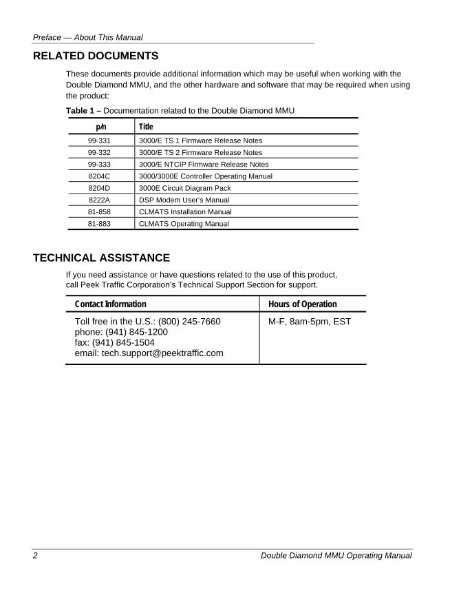
RELATED DOCUMENTS These documents provide additional information which may be useful when working with the Double Diamond MMU, and the other hardware and software that may be required when using the product:
Table 1 – Documentation related to the Double Diamond MMU
p/n Title 99-331 3000/E TS 1 Firmware Release Notes 99-332 3000/E TS 2 Firmware Release Notes 99-333 3000/E NTCIP Firmware Release Notes 8204C 3000/3000E Controller Operating Manual 8204D 3000E Circuit Diagram Pack 8222A DSP Modem User’s Manual 81-858 CLMATS Installation Manual 81-883 CLMATS Operating Manual
TECHNICAL ASSISTANCE If you need assistance or have questions related to the use of this product, call Peek Traffic Corporation’s Technical Support Section for support.
Contact Information Hours of Operation
Toll free in the U.S.: (800) 245-7660 phone: (941) 845-1200 fax: (941) 845-1504 email: [email protected]
M-F, 8am-5pm, EST
Double Diamond MMU Operating Manual 3
Chapter 1 — Introduction to the Double Diamond MMU
This chapter introduces the concept of the Malfunction Management Unit (MMU) and describes how the Double Diamond fills that role. The following topics are discussed in detail in this chapter:
• Introduction to the role of an MMU, on page 4.
• Operating modes of the Double Diamond MMU, on page 5.
• Advanced features of the Double Diamond, on page 7.
• An introduction to the monitoring modes that are available, on page 9.
• A set of quick setup instructions for operators with previous exposure to MMUs, on page 11.
Chapter 1 — Introduction to the Double Diamond MMU
4 Double Diamond MMU Operating Manual
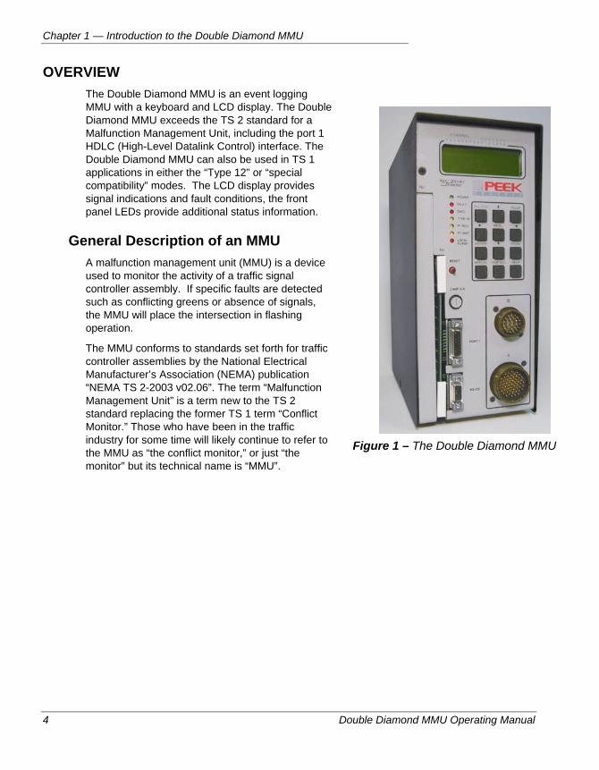
OVERVIEW The Double Diamond MMU is an event logging MMU with a keyboard and LCD display. The Double Diamond MMU exceeds the TS 2 standard for a Malfunction Management Unit, including the port 1 HDLC (High-Level Datalink Control) interface. The Double Diamond MMU can also be used in TS 1 applications in either the “Type 12” or “special compatibility” modes. The LCD display provides signal indications and fault conditions, the front panel LEDs provide additional status information.
General Description of an MMU A malfunction management unit (MMU) is a device used to monitor the activity of a traffic signal controller assembly. If specific faults are detected such as conflicting greens or absence of signals, the MMU will place the intersection in flashing operation.
The MMU conforms to standards set forth for traffic controller assemblies by the National Electrical Manufacturer’s Association (NEMA) publication “NEMA TS 2-2003 v02.06”. The term “Malfunction Management Unit” is a term new to the TS 2 standard replacing the former TS 1 term “Conflict Monitor.” Those who have been in the traffic industry for some time will likely continue to refer to the MMU as “the conflict monitor,” or just “the monitor” but its technical name is “MMU”.
Figure 1 – The Double Diamond MMU
Double Diamond MMU Operational Modes
Double Diamond MMU Operating Manual 5
DOUBLE DIAMOND MMU OPERATIONAL MODES True TS 1 mode — TS 1 compatible using a TS 1 card. 12 R-Y-G-W channels. Port 1 comm not required. The unit assumes True TS 1 operation when a TS 1 (old style, smaller) card is inserted.
TS 2 Type 12 — TS 1 compatible with but with TS 2 card. 12 R-Y-G-W channels. Port 1 comm not required. The unit assumes TS 2 type 12 operation when a TS 2 (new style, larger) card is inserted, but the type input is (A-HH) is not true.
TS 2 Type 16 — TS 2 compatible with 16 R-Y-G channels. Port 1 comm required unless defeated by applying logic ground to Port 1 pin 10 (see page 122). The unit assumes TS 2 type 16 operation when a TS 2 (large) card is inserted, and the type input is (A-HH) is true.
ELRA/ELRB/LSM/LNME Compatible Mode — (special). Internal DC electrical jumpers must be modified. The I/O is configured for compatibility with ELRA/ELRB/LSM/LNME monitors (Status bits, DC Red Mon inhibit)
Caution Do not install a Double Diamond MMU that has been configured with DC
jumpers to operate in ELRA/ELRB/LSM/LNME compatible mode into a TS 2 Type 16 wired cabinet. Extreme damage will likely result.
For more details on this, refer to page 32.
TS 2 Backward Compatibility The field connectors used in the TS 2 version are physically the same as those used in TS 1 conflict monitors. By NEMA definition, the MMU is downward compatible to TS 1 operation by use of the Type 12 mode. Port 1 operation is not required in this mode and the field input configuration is per TS 1. The Type 16 mode is invoked by logic grounding a new input (MSA pin HH). This pin was formally a spare in the TS 1 standard, thus cabinets wired for TS 1 operation would automatically default to TS 1 type 12 mode (the pin should not be grounded). When type 16 mode is invoked, port 1 operation is required and the field input configuration is per TS 2 type 16. Note that the Double Diamond MMU surpasses NEMA requirements by also allowing use of the TS 1 card.
Additional Features Available in TS 2 Mode The major differences between a TS 2 MMU (such as the Double Diamond) and a TS 1 Conflict Monitor are described below.
Port 1 Interface The MMU provides an EIA-485 synchronous serial communications port for interface to the controller unit. The protocol is based on the IBM SDLC (Synchronous Data Link Control) protocol. The information field formats, frame types, content, and data exchanged between the controller, MMU, and other devices are defined in the TS 2 standard. The serial port allows the controller to inform the MMU of its desired output configuration. Conversely, the MMU can inform the controller of its AC field signal status, its compatibility program card configuration, relay status, etc.
Chapter 1 — Introduction to the Double Diamond MMU
6 Double Diamond MMU Operating Manual
Expanded Channels The MMU in the “type 16 mode” has up to 16 channels with three 120V inputs on each one (Green/Walk, Yellow, or Red/Don’t Walk.) The type 12 mode is the same as the TS 1 conflict monitor in that it has twelve R, Y, G, or W channels. (Refer to NEMA TS 2-2003, Section 4.1.)
Defined Feature Set Some of the features that had become to be regarded as “NEMA plus” features prior to TS 2 are now incorporated in the standard. These include minimum clearance interval plus CVM and 24 VDC fail latching.
New Jumper Card By NEMA definition, a TS 2 MMU would only use the new compatibility programming card which is not compatible with old cards from existing TS 1 monitors. Included on the card is; 16 channel compatibility jumpers, minimum yellow disable jumpers for each channel, min flash timing jumpers, plus 24 and CVM latch jumpers. To make downward compatibility easier, however, the DIAMOND MMU has been designed to accept both TS 1 and TS 2 style cards.
Other Advanced Features of the DD MMU
Double Diamond MMU Operating Manual 7
OTHER ADVANCED FEATURES OF THE DD MMU The following features exceed the standard TS 2 specification:
Dual Programming Cards The Double Diamond MMU can accept both TS 1 and TS 2 style Programming Cards. This allows the unit to serve as both a true TS 1 and TS 2 unit and is fully downward compatible without need of installing jumpers in a TS 2 card just to duplicate an existing TS 1 card when the Double Diamond is substituted for a TS 1 conflict monitor.
Voltage Measuring and Displaying The Double Diamond MMU analog to digital processes AC line, Red Enable, and all 48 signal inputs to give numeric readouts of each of 48 signal inputs in volts AC.
Full R-Y-G-W Status on the LCD Display plus status of all I/O and Programming Card jumpers, and port 1 comm.
Port 1, Type 16 Run Screen Mode To view R-Y-G status per the message frames sent by the controller (in addition to normal status as determined by field AC inputs).
Special “Auto GY vs R” Feature This feature allows factory to set GY vs R on all channels. The mode does not become officially enabled until the channel red cycles off one time after power-up. Protects against dark approaches during red.
Special “Display G as W” Programming Allows a ped channel (with walk on green) to be configured so that when the green is on a “W” is displayed. Useful for type 16 mode where walks must be monitored on green (no walk inputs).
Replay Special push-button which allows the user to replay up to the last 20 G-Y-R displays leading up to either; the active display at the moment pressed, the current fault, or any historical fault logged in memory. The replay displays each indicate the screen’s time duration and can be stepped manually through the displays.
Chapter 1 — Introduction to the Double Diamond MMU
8 Double Diamond MMU Operating Manual
Event Log Each event log provides the time, date, and type of event, plus an “additional information screen” which, in the case of faults, contains the G-Y-R status, port 1 comm status (if port 1 enabled), plus the replay screens leading up to the fault at the time of fault.
If it is the very last recorded fault, however, the full compliment of unit status is recorded and is available, including:
-The Relay and DC Input status screen
-The Voltage screens
-The Programming Card screens
Over Voltage and Low Voltage Recording The user can specify the thresholds over which or under which the unit will record. The record includes the time, date and voltages.
Blinking Signals Log The unit records signals that briefly “blink on” or “blink off” These are not long enough to cause conflict or red fail, but are recorded for evaluation. If Blink Logs fill up the Event Log and make finding faults that cause flash conditions difficult to capture, the blink logs can be disabled (per channel) on the MM > Config > Monitor > Per Chan menu. Blinks are most typically caused by load switches that are not precisely zero crossing.
Monitoring Modes
Double Diamond MMU Operating Manual 9
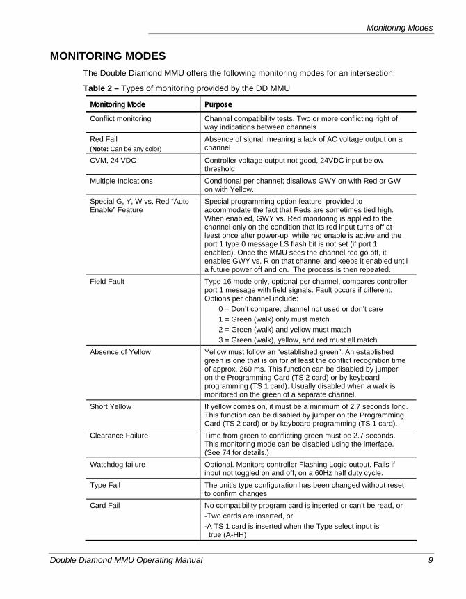
MONITORING MODES The Double Diamond MMU offers the following monitoring modes for an intersection.
Table 2 – Types of monitoring provided by the DD MMU
Monitoring Mode Purpose Conflict monitoring Channel compatibility tests. Two or more conflicting right of
way indications between channels Red Fail (Note: Can be any color)
Absence of signal, meaning a lack of AC voltage output on a channel
CVM, 24 VDC Controller voltage output not good, 24VDC input below threshold
Multiple Indications Conditional per channel; disallows GWY on with Red or GW on with Yellow.
Special G, Y, W vs. Red “Auto Enable” Feature
Special programming option feature provided to accommodate the fact that Reds are sometimes tied high. When enabled, GWY vs. Red monitoring is applied to the channel only on the condition that its red input turns off at least once after power-up while red enable is active and the port 1 type 0 message LS flash bit is not set (if port 1 enabled). Once the MMU sees the channel red go off, it enables GWY vs. R on that channel and keeps it enabled until a future power off and on. The process is then repeated.
Field Fault Type 16 mode only, optional per channel, compares controller port 1 message with field signals. Fault occurs if different. Options per channel include:
0 = Don’t compare, channel not used or don’t care 1 = Green (walk) only must match 2 = Green (walk) and yellow must match 3 = Green (walk), yellow, and red must all match
Absence of Yellow Yellow must follow an “established green”. An established green is one that is on for at least the conflict recognition time of approx. 260 ms. This function can be disabled by jumper on the Programming Card (TS 2 card) or by keyboard programming (TS 1 card). Usually disabled when a walk is monitored on the green of a separate channel.
Short Yellow If yellow comes on, it must be a minimum of 2.7 seconds long. This function can be disabled by jumper on the Programming Card (TS 2 card) or by keyboard programming (TS 1 card).
Clearance Failure Time from green to conflicting green must be 2.7 seconds. This monitoring mode can be disabled using the interface. (See 74 for details.)
Watchdog failure Optional. Monitors controller Flashing Logic output. Fails if input not toggled on and off, on a 60Hz half duty cycle.
Type Fail The unit’s type configuration has been changed without reset to confirm changes
Card Fail No compatibility program card is inserted or can’t be read, or -Two cards are inserted, or -A TS 1 card is inserted when the Type select input is true (A-HH)
Chapter 1 — Introduction to the Double Diamond MMU
10 Double Diamond MMU Operating Manual
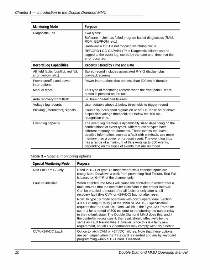
Monitoring Mode Purpose Diagnostic Fail Two types:
Software = Unit has failed program based diagnostics (RAM, ROM, EEPROM, etc.) Hardware = CPU is not toggling watchdog circuit RECORD LOG CAPABILITY = Diagnostic failures can be logged to the event log, stored by the date and time that the error occurred.
Record Log Capabilities Records Stored by Time and Date All field faults (conflict, red fail, short yellow, etc.)
Stored record includes associated R-Y-G display, plus playback screens
Power on/off’s and power interruptions
Power interruptions that are less than 500 ms in duration
Manual reset This type of monitoring records when the front panel Reset button is pressed on the unit.
Auto recovery from flash i.e. from non-latched failures Voltage log records User settable above & below thresholds to trigger record Blinking (intermittent) signals Counts spurious short signals on or off, i.e. those on or above
a specified voltage threshold, but below the 100 ms recognition time.
Event log capacity The event log memory is dynamically sized depending on the combinations of event types. Different event types have different memory requirements. Those events that have detailed information, such as a fault with playback, use more memory than a power on or reset event. The event log thus has a range of a minimum of 82 events up to 800 events, depending on the types of events that are recorded.
Table 3 – Special monitoring options
Special Monitoring Mode Purpose Red Fail R-Y-G Only Used in TS 1 or type 12 mode where walk channel inputs are
recognized. Disallows a walk from preventing Red Failure. Red Fail is based on G-Y-R of the channel only.
Fault re-initialize When enabled, the MMU will cause the controller to restart after a fault. Insures that the controller exits flash in the proper interval. Can be enabled to restart after all faults or only after a self recovery fault (like CVM or +24VDC) but not after reset. Note: In type 16 mode operation with port 1 operational, Section 4.3.4.1 (“Output Relay”) of the 1998 NEMA TS 2 specification requires that the Start-Up Flash Call bit in the Type 129 Frame be set to 1 for a period of 500 ms prior to transferring the output relay to the no-fault state. The Double Diamond MMU does this, and if the controller recognizes it, the result should effectively be the same as Fault Re-initialize. However, since this is a fairly new requirement, not all TS 2 controllers may comply with this function.
CVM/+24VDC Latch Option to latch CVM or +24VDC failures. Note that these options are per jumper when the TS 2 card is inserted and are by keyboard programming when a TS 1 card is inserted.
Quick Set-Up Instructions
Double Diamond MMU Operating Manual 11
QUICK SET-UP INSTRUCTIONS The following abbreviated procedures are for users who are already familiar with the Double Diamond, or MMUs in general, and who only need quick guidelines to get started with the setup of the unit.
Installation Notes
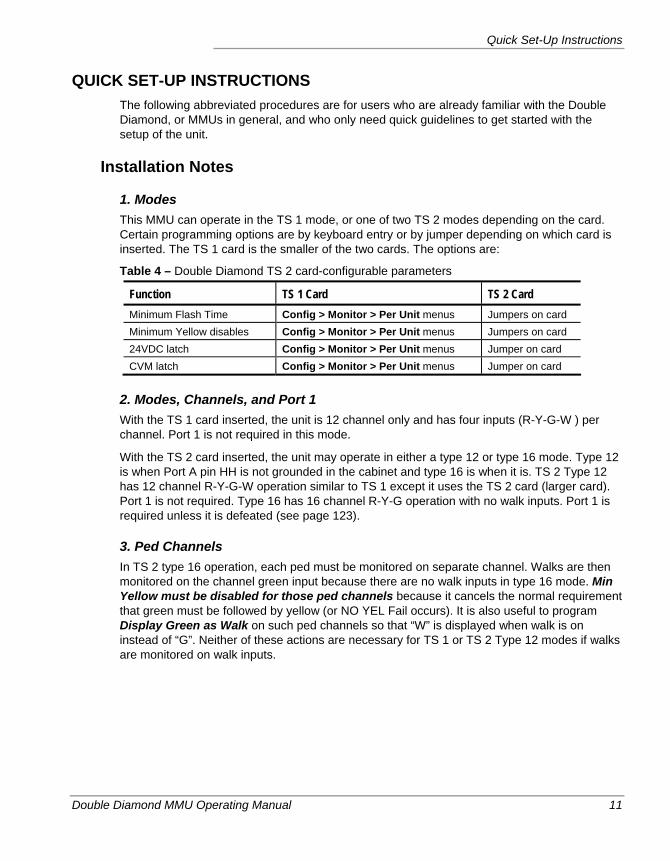
1. Modes This MMU can operate in the TS 1 mode, or one of two TS 2 modes depending on the card. Certain programming options are by keyboard entry or by jumper depending on which card is inserted. The TS 1 card is the smaller of the two cards. The options are:
Table 4 – Double Diamond TS 2 card-configurable parameters
Function TS 1 Card TS 2 Card Minimum Flash Time Config > Monitor > Per Unit menus Jumpers on card Minimum Yellow disables Config > Monitor > Per Unit menus Jumpers on card 24VDC latch Config > Monitor > Per Unit menus Jumper on card CVM latch Config > Monitor > Per Unit menus Jumper on card
2. Modes, Channels, and Port 1 With the TS 1 card inserted, the unit is 12 channel only and has four inputs (R-Y-G-W ) per channel. Port 1 is not required in this mode.
With the TS 2 card inserted, the unit may operate in either a type 12 or type 16 mode. Type 12 is when Port A pin HH is not grounded in the cabinet and type 16 is when it is. TS 2 Type 12 has 12 channel R-Y-G-W operation similar to TS 1 except it uses the TS 2 card (larger card). Port 1 is not required. Type 16 has 16 channel R-Y-G operation with no walk inputs. Port 1 is required unless it is defeated (see page 123).
3. Ped Channels In TS 2 type 16 operation, each ped must be monitored on separate channel. Walks are then monitored on the channel green input because there are no walk inputs in type 16 mode. Min Yellow must be disabled for those ped channels because it cancels the normal requirement that green must be followed by yellow (or NO YEL Fail occurs). It is also useful to program Display Green as Walk on such ped channels so that “W” is displayed when walk is on instead of “G”. Neither of these actions are necessary for TS 1 or TS 2 Type 12 modes if walks are monitored on walk inputs.
Chapter 1 — Introduction to the Double Diamond MMU
12 Double Diamond MMU Operating Manual
General Guidelines During Setup 1. MM = Main Menu, go to the R-Y-G (Normal status) display if not already displayed and
press MENU. This is the Main Menu.
2. Use the arrow buttons to select a menu. The cursor is indicated by a flashing asterisk. Press ENTER to implement that menu.
3. When entering the CONFIG MENU, an instruction page first appears, hit ENTER again to pass through this screen.
4. To configure the unit, use left and right arrows to move the cursor, up/down arrows to scroll values. Be sure to press ENTER to implement before exiting the screen. Press the RYG Stat button to return to the Normal Status screen.
5. The unit has menu selection memory, i.e. it will follow the same path through the menus as last used (if no power interruptions have occurred). Thus, if you are programming the same item as the last time you navigated the menus, just select MENU and keep hitting ENTER to follow the same path.
6. Many screens can be accessed by paging down (PGDN) from the previous screen.
7. Press the REPLAY key to display the screens that lead up to a fault. Once in this mode, hit PGDN each time to go back one more screen prior to the event.
Configuring Global Settings These are the items that need to be configured on a unit-wide basis. The following listing is a suggested order, but you need not follow it exactly. Just be sure to check each of these settings at least once before deploying the unit. Unit-wide settings are functions that are not channel related or that apply to all channels when they are enabled.
1. Set Field Check Enable–Unit Wide This setting must also be set on a per channel basis, if used.
Go to MM > CONFIG >MONITOR > PER UNIT > 1st PAGE and select a value for FIELD CHECK ENAB. The available values are: 0 = OFF, 1=ON.
2. Set Red Fail G-Y-R Only This setting is only important for 12 channel modes only. (TS 2 Type 16 has no defined ‘walk’ inputs.) See also the Per Channel configuration.
Go to MM > CONFIG > MONITOR > PER UNIT > 1st PAGE and select a value for RED FAIL R-Y-G ONLY. The available values are 0 = OFF, 1=ON.
Quick Set-Up Instructions
Double Diamond MMU Operating Manual 13
3. Set Fault Re-Initialize This setting tells the MMU whether or not it should re-initialize the traffic controller after a fault event, so that it exits Flash properly.
Go to MM > CONFIG > MONITOR > PER UNIT > 1st PAGE and select a value for FAULT RE-INTIALIZE. The available values are:
0 = OFF, which does not re-initialize the controller
1 = Re-initialize the controller after both reset and non-latched, self healing faults such as CVM or +24V Fail.
2 = Re-initialize after non-latched, self healing faults only (but not after reset)
4. Set Watchdog Enable This tells the MMU to monitor the controller’s flashing logic. This signal must be wired to pin S on Port B.
Go to MM > CONFIG > MONITOR > PER UNIT > 2nd PAGE and select a value for WATCHDOG ENAB. The available values are: 0 = OFF, 1=ON.
5. Set TS 1 24V or CVM Latch This step is necessary only if a TS 1 card is installed in the unit. (These values are set by jumpers on a TS 2 card.)
Go to MM > CONFIG > MONITOR > PER UNIT > 2nd PAGE and select values for the +24V LATCH and the CVM LATCH. The available values are: 0 = OFF, 1=ON.
6. Set TS 1 Min Flash Time This only applies if a TS 1 card is inserted in the unit. (This value is set by jumpers if you are using a TS 2 card.)
Go to MM > CONFIG > MONITOR > PER UNIT > 3rd PAGE and select a value for the MIN FLASH setting. The available values are: 4-10 seconds.
7. Set Canadian Fast Flash Mode This is used when fast flashing left turns are used as indications.
Go to MM > CONFIG > MONITOR > PER UNIT > 4th PAGE and select a value for the FAST FLASH ENABLE setting. The available values are: 0 = OFF, 1=ON.
8. Set Status Bit ABC Mode This is used when the LSM/LNM/ELRB/ELRA emulation DC jumpers are in place. It defines the output mode.
Go to MM > CONFIG > MONITOR > PER UNIT > 5th PAGE and set the STATUS MODE parameter. The available values are: 0=LSM/LNM/ELRB, 1=ELRA.
Chapter 1 — Introduction to the Double Diamond MMU
14 Double Diamond MMU Operating Manual
Configuring Channel by Channel Settings These are the items that need to be configured on a ‘per channel’ basis. These settings use the channel numbers that are printed above the LCD display to indicate the setting for each of the 16 channels. The order of these instructions is merely a suggestion and need not be followed religiously. And please be aware that the following settings apply only to channels that are enabled.
1. Setting GWY vs. R Enables Green, walk, or yellow cannot be on with red or a MULT IND fault occurs.
Go to MM > CONFIG > MONITOR > PER CHAN > GWY vs. R and choose a setting for each channel from these options:
0 = Off, does not care if GWY on with Red for that channel.
1 = On, does not allow GWY on with Red for that channel unconditionally 2 = AUTO, does not allow GWY on with Red for that channel after red cycles off one time
(default mode)
2. Setting GW vs. Yellow Enables If set to ON for a channel, then a Green or Walk cannot be on with Yellow on that channel. If they are on together, then a MULT IND fault occurs.
Simply PGDN from the previous screen, or go to MM > CONFIG > MONITOR > PER CHAN > GW vs. Y and choose a setting for each channel from these options: 0 = OFF, 1=ON.
3. Display Green As Walk This optional setting is used when Walk is monitored on one or more channels and Walk is ON. When these conditions are met, a “W” will appear on the Normal Status screen instead of a “G” to show the Walk ON state.
Simply PGDN from the previous screen, or go to MM > CONFIG > MONITOR > PER CHAN > CHN=WLK and choose a setting for each channel from these options: 0 = OFF, 1=ON.
4. Set up Field Check Enables This option checks the field against controller port 1 info. This setting must also be enabled globally in the Per Unit settings.
Simply pgdn from the previous screen, or go to MM > CONFIG > MONITOR > PER CHAN > FIELD CHK and choose a setting for each channel from these options:
0 = Off, no channel R, Y or G matching required
1 = Chan Green (walk) only must match
2 = Chan Green (walk) and yellow must match
3 = Green (walk), yel, and red must match
Quick Set-Up Instructions
Double Diamond MMU Operating Manual 15
5. Disable Minimum Yellow Monitoring in TS 1 Environments
This setting is only required if a TS 1 card is installed in the unit. (It can be set using jumpers on a TS 2 card.)
Simply PGDN from the previous screen, or go to MM > CONFIG > MONITOR > PER CHAN > MIN YEL and choose a setting for each channel from these options: 0 = MIN YELLOW ENABLED, 1 = DISABLED.
Note ‘Min Yellow Disable’ disables “Short Yellow” and “No Yellow” (absence of yellow) monitoring, but does not disable “Clearance Failure” = time from the end of green to the next conflicting green. Min Yellow Disable should be applied to channels where yellow is not expected to follow green, such as when walk is monitored on green, especially when using TS 2 type 16 mode.
6. Set RED FAIL R-Y-G ONLY in 12 Channel Environments This is only necessary for 12 channel modes. (TS 2 Type 16 has no walks) This setting must also be set in the global (Per Unit) parameters for it to function properly.
Simply PGDN from the previous screen, or go to MM > CONFIG > MONITOR > PER CHAN > RYG ONLY and choose a setting for each channel from these options: 0 = OFF, 1 = ON. When this value is enabled (ON), Walk cannot prevent Red failure.
7. Set up Clearance Failure Inihibits (GG INHIB) This disables clearance failures. To enable this for active channels, go to MM > CONFIG > MONITOR > PER CHAN > PGDN. Choose the setting for each channel from these options: 0 = Green to Conflict Green Monitoring ON 1 = Green to Conflict Green Monitoring OFF (inhibited)
8. Set Date and Time in TS 1 Environments Go to MM > Config > Set Time and use the left and right arrows to move the cursor and the up and down arrows to change the numbers. Enable or disable daylight savings time.
9. Enable the Blink Log Blink events can quickly fill up the Event Log, making it hard to view other fault events. To turn off (inhibit) blink logging, go to MM > CONFIG > MONITOR > PER CHANNEL > PGDN > BLINK LOG. Choose the setting for each channel. The Blink Log is ON by default, so the options are 0 = Blink Log Inhibit is OFF (i.e. Blink Logs will be recorded for this channel) and 1 = Blink Log Inhibit is ON (i.e. Blink Logs will not be recorded for this channel.) To inhibit blink logs, set all channels to 1.
Chapter 1 — Introduction to the Double Diamond MMU
16 Double Diamond MMU Operating Manual
10. Set a Security Code This is not a ‘Per Chan’ setting, but since it can interfere with quick set up of the unit, we’ve left this global setting until the end of the quick setup process. If you want your MMU to prevent inadvertent or unauthorized changes to its configuration, you should enable the security system by setting its code to something other than ‘0000’.
Go to MM > CONFIG > SEC CODE and fill in a four-digit security code number.
Important Write this number down somewhere!
Double Diamond MMU Operating Manual 17
Chapter 2 — Double Diamond Hardware
This chapter introduces and details the Double Diamond MMU hardware. The following topics are discussed in detail in this chapter:
• An introduction to the Double Diamond hardware, on page 18.
• Descriptions of the front panel controls of the unit, on page 19.
• A discussion about the Programming Card, on page 25.
• A description of the operation of Port 1, on page 30.
• How to configure the unit to emulate ELRA/ELRB/LSM or LNME monitors, on page 32.
Chapter 2 — Double Diamond Hardware
18 Double Diamond MMU Operating Manual
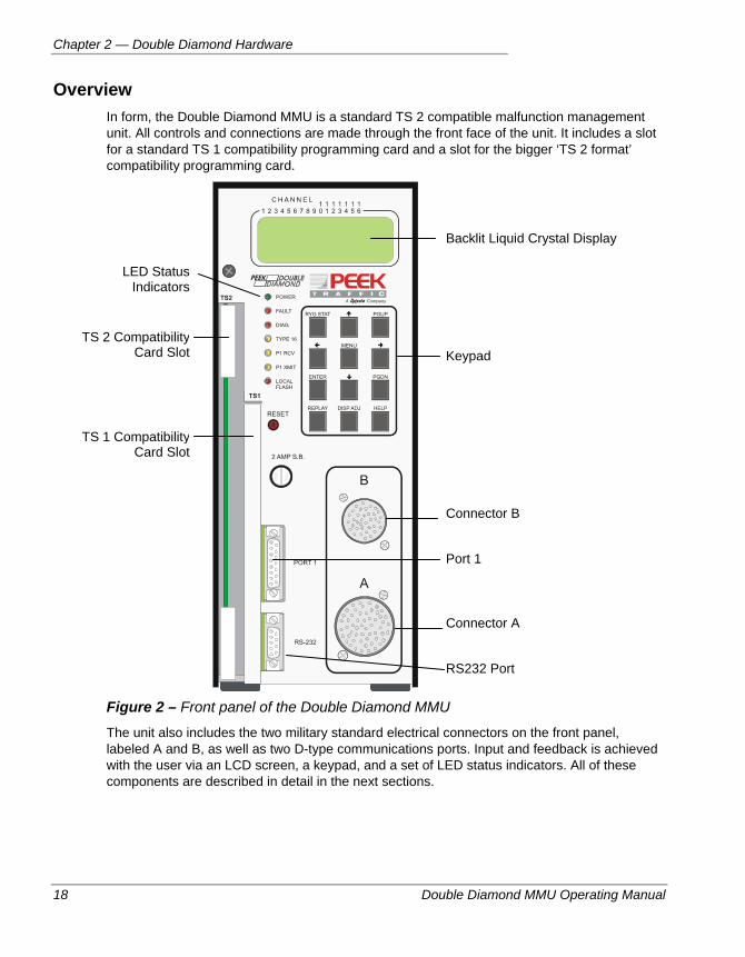
Overview In form, the Double Diamond MMU is a standard TS 2 compatible malfunction management unit. All controls and connections are made through the front face of the unit. It includes a slot for a standard TS 1 compatibility programming card and a slot for the bigger ‘TS 2 format’ compatibility programming card.
Figure 2 – Front panel of the Double Diamond MMU
The unit also includes the two military standard electrical connectors on the front panel, labeled A and B, as well as two D-type communications ports. Input and feedback is achieved with the user via an LCD screen, a keypad, and a set of LED status indicators. All of these components are described in detail in the next sections.
Backlit Liquid Crystal Display
Keypad
Connector B
Connector A
Port 1
RS232 Port
LED Status Indicators
TS 2 Compatibility Card Slot
TS 1 Compatibility Card Slot
Front Panel Controls and Indicators
Double Diamond MMU Operating Manual 19
FRONT PANEL CONTROLS AND INDICATORS The purpose and usage of each button, control and indicator on the front panel of the Double Diamond MMU are described in the next sections.
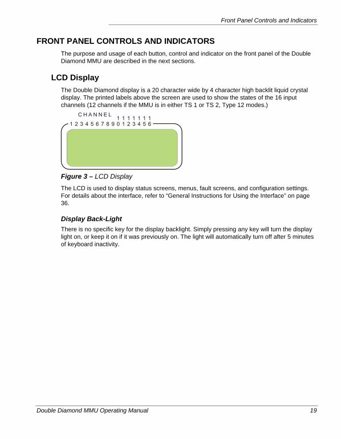
LCD Display The Double Diamond display is a 20 character wide by 4 character high backlit liquid crystal display. The printed labels above the screen are used to show the states of the 16 input channels (12 channels if the MMU is in either TS 1 or TS 2, Type 12 modes.)
Figure 3 – LCD Display
The LCD is used to display status screens, menus, fault screens, and configuration settings. For details about the interface, refer to “General Instructions for Using the Interface” on page 36.
Display Back-Light There is no specific key for the display backlight. Simply pressing any key will turn the display light on, or keep it on if it was previously on. The light will automatically turn off after 5 minutes of keyboard inactivity.
Chapter 2 — Double Diamond Hardware
20 Double Diamond MMU Operating Manual
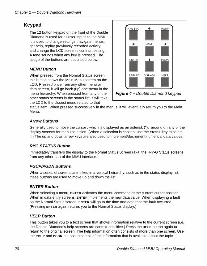
Keypad The 12 button keypad on the front of the Double Diamond is used for all user inputs to the MMU. It is used to change settings, navigate menus, get help, replay previously recorded activity, and change the LCD screen’s contrast setting. A tone sounds when any key is pressed. The usage of the buttons are described below.
MENU Button When pressed from the Normal Status screen, this button shows the Main Menu screen on the LCD. Pressed once from any other menu or data screen, it will go back (up) one menu in the menu hierarchy. When pressed from any of the other status screens in the status list, it will take the LCD to the closest menu related to that status item. When pressed successively in the menus, it will eventually return you to the Main Menu.
Arrow Buttons Generally used to move the cursor , which is displayed as an asterisk (*), around on any of the display screens for menu selection. (When a selection is chosen, use the ENTER key to select it.) The up and down arrow keys are also used to increment/decrement numerical data values.
RYG STATUS Button Immediately transfers the display to the Normal Status Screen (aka, the R-Y-G Status screen) from any other part of the MMU interface.
PGUP/PGDN Buttons When a series of screens are linked in a vertical heirarchy, such as in the status display list, these buttons are used to move up and down the list.
ENTER Button When selecting a menu, ENTER activates the menu command at the current cursor position. When in data entry screens, ENTER implements the new data value. When displaying a fault on the Normal Status screen, ENTER will go to the time and date that the fault occurred (Pressing ENTER again returns you to the Normal Status display.)
HELP Button This button takes you to a text screen that shows information relative to the current screen (i.e. the Double Diamond’s help screens are context-sensitive.) Press the HELP button again to return to the original screen. The help information often consists of more than one screen. Use the PGUP and PGDN buttons to see all of the information that is available about the topic.
Figure 4 – Double Diamond keypad
Front Panel Controls and Indicators
Double Diamond MMU Operating Manual 21
DISP ADJ Button The Display Adjustment button is used to modify the contrast setting of the MMU’s LCD display. Press it repeatedly to increase the contrast of the display, until the screen is most easily legible from your viewing angle. The screen has 16 levels of contrast. This contrast setting wraps around to the low contrast level.
REPLAY Button The Replay button can be used to play back the last 20 Normal Status screens as recorded by the Double Diamond. These status screens are latched and stored with the event log after fault occurrences. For more details about Replay mode, refer to page 107.
TS 2 Programming Card Slot This slot will accept a single Programming Card that meets the TS 2 Programming Card standard. The MMU should house only one Programming Card, either a TS 1 or TS 2 card. To insert a card here, remove power from the unit and remove the old card. Slide the card in with the sockets at the rear and press the card firmly into the slot using the two plastic corner pieces.
To remove the card, remove power from the MMU and allow it to lose residual charge by waiting a few seconds. Lift the two plastic corner brackets to force the card out of the slot.
For more details about the Programming Cards and how to configure them, refer to page 25.
Note The TS 2 card slot may be covered if the unit was shipped from the factory as a TS 1 unit. To allow the installation of a TS 2 card, you will need to remove the metal cover from the slot. The cover is held in place by a single, Philips-head screw at the bottom of the unit.
TS 1 Programming Card Slot This slot will accept a single Programming Card that meets the TS 1 Programming Card standard. The MMU should house only one Programming Card, either a TS 1 or TS 2 card. To insert a card here, remove power from the unit and remove the old card. Slide the card in with the connector pads toward the rear of the unit, and press the card firmly into the slot.
To remove the card, remove power from the MMU and allow it to lose residual charge by waiting a few seconds. Lift the two plastic corner brackets to force the card out of the slot.
For more details about the Programming Cards and how to configure them, refer to page 25.
Note The TS 1 card slot may be covered if the unit was shipped from the factory as a TS 2 unit. To allow the installation of a TS 1 card, you will need to remove the metal cover from the TS 1 slot. The cover is held in place by a single, Philips-head screw at the bottom of the unit.
Chapter 2 — Double Diamond Hardware
22 Double Diamond MMU Operating Manual
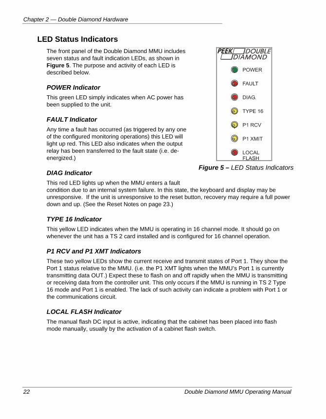
LED Status Indicators The front panel of the Double Diamond MMU includes seven status and fault indication LEDs, as shown in Figure 5. The purpose and activity of each LED is described below.
POWER Indicator This green LED simply indicates when AC power has been supplied to the unit.
FAULT Indicator Any time a fault has occurred (as triggered by any one of the configured monitoring operations) this LED will light up red. This LED also indicates when the output relay has been transferred to the fault state (i.e. de-energized.)
DIAG Indicator This red LED lights up when the MMU enters a fault condition due to an internal system failure. In this state, the keyboard and display may be unresponsive. If the unit is unresponsive to the reset button, recovery may require a full power down and up. (See the Reset Notes on page 23.)
TYPE 16 Indicator This yellow LED indicates when the MMU is operating in 16 channel mode. It should go on whenever the unit has a TS 2 card installed and is configured for 16 channel operation.
P1 RCV and P1 XMT Indicators These two yellow LEDs show the current receive and transmit states of Port 1. They show the Port 1 status relative to the MMU. (i.e. the P1 XMT lights when the MMU’s Port 1 is currently transmitting data OUT.) Expect these to flash on and off rapidly when the MMU is transmitting or receiving data from the controller unit. This only occurs if the MMU is running in TS 2 Type 16 mode and Port 1 is enabled. The lack of such activity can indicate a problem with Port 1 or the communications circuit.
LOCAL FLASH Indicator The manual flash DC input is active, indicating that the cabinet has been placed into flash mode manually, usually by the activation of a cabinet flash switch.
Figure 5 – LED Status Indicators
Front Panel Controls and Indicators
Double Diamond MMU Operating Manual 23
Reset Button The reset push-button clears any latched failures and causes the output relay to energize. The reset button also re-configures the unit, for example if the type 12 or 16 mode has been changed. An audible tone sounds whenever the reset button is activated. Reset is a one-time operation and cannot be permanently invoked (See note 2 below.)
Important Notes About Resetting the Double Diamond 1. Caution should be exercised when resetting from a fault condition, as the signals may abruptly change from flashing to automatic operation. Consideration should always be given as to how the signals are flashing and to what controller interval will immediately follow flash. Review the Proper Procedures for Resetting and Exiting Flash below.
2. The reset state cannot be permanently invoked. Reset is a one-time operation. Continuous activation of the button will not disable any MMU monitoring functions. The reset button must be released then re-applied for a new reset.
3. The 1998 NEMA TS 2 (and retained in the 2003 version) specification added a requirement (4.3.4.1) that states when transferring the output relay “from the fault state to the no fault state, a transition state of 500 milliseconds shall occur.” During this period the output relay will remain in the fault state and the Start-up Flash bit in the Port 1 type 129 frame will be set to 1. The controller is then required to re-initialize itself upon recognition of this bit (i.e. after a reset, or self heal recovery such as from CVM or 24 VDC fail). This function then has the same result as the Fault Re-initialize feature (see page 90) and would suffice in its place. The Double Diamond MMU does meet this requirement. However, since it was added in 1998, there are two versions of TS 2 controllers that do not respond to the Start-up bit. Thus, the capability of the TS 2 controller should be evaluated to determine if this capability exists. If not, Fault Re-initialize may be used instead.
Fuse The Double Diamond requires a 2 Amp, 250V standard 1¼” tubular fuse. It is housed in a fuse holder that can be accessed from the front of the MMU. To access the fuse, turn the notched fuse holder 1/8th turn counter-clockwise.
Port 1 Port 1 of the DD MMU is a standard MMU port 1 as described in sections 3.3.1 and 4.3.1 of the NEMA TS 2-2003 standard. The plug is a 15-pin metal-shell D subminiature type. Port 1 is the primary connector for attaching the controller to the MMU in a TS 2 cabinet. Port 1 is typically not used in a TS 1 cabinet, since the Double Diamond runs only as a simple conflict monitor in that situation. For more information about the operation of Port 1, refer to page 30. For Port 1 pin assignments, refer to page 122.
Chapter 2 — Double Diamond Hardware
24 Double Diamond MMU Operating Manual
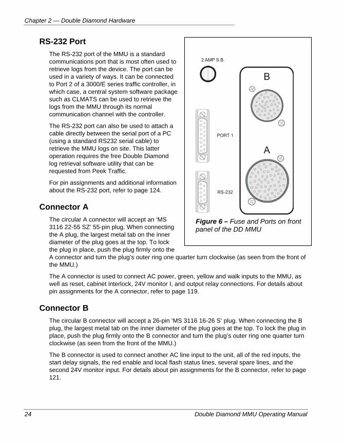
RS-232 Port The RS-232 port of the MMU is a standard communications port that is most often used to retrieve logs from the device. The port can be used in a variety of ways. It can be connected to Port 2 of a 3000/E series traffic controller, in which case, a central system software package such as CLMATS can be used to retrieve the logs from the MMU through its normal communication channel with the controller.
The RS-232 port can also be used to attach a cable directly between the serial port of a PC (using a standard RS232 serial cable) to retrieve the MMU logs on site. This latter operation requires the free Double Diamond log retrieval software utility that can be requested from Peek Traffic.
For pin assignments and additional information about the RS-232 port, refer to page 124.
Connector A The circular A connector will accept an ‘MS 3116 22-55 SZ’ 55-pin plug. When connecting the A plug, the largest metal tab on the inner diameter of the plug goes at the top. To lock the plug in place, push the plug firmly onto the A connector and turn the plug’s outer ring one quarter turn clockwise (as seen from the front of the MMU.)
The A connector is used to connect AC power, green, yellow and walk inputs to the MMU, as well as reset, cabinet interlock, 24V monitor I, and output relay connections. For details about pin assignments for the A connector, refer to page 119.
Connector B The circular B connector will accept a 26-pin ‘MS 3116 16-26 S’ plug. When connecting the B plug, the largest metal tab on the inner diameter of the plug goes at the top. To lock the plug in place, push the plug firmly onto the B connector and turn the plug’s outer ring one quarter turn clockwise (as seen from the front of the MMU.)
The B connector is used to connect another AC line input to the unit, all of the red inputs, the start delay signals, the red enable and local flash status lines, several spare lines, and the second 24V monitor input. For details about pin assignments for the B connector, refer to page 121.
Figure 6 – Fuse and Ports on front panel of the DD MMU
Programming Cards
Double Diamond MMU Operating Manual 25
PROGRAMMING CARDS Programming Cards are a method defined in the NEMA TS 1 and TS 2 standards for transferring a particular intersection’s phase/traffic movement compatibilities from one CMU or MMU to another. All Peek MMUs can accept either type of Programming Card. The TS 2 standard specifies a larger card that contains not only compatibility information, but also minimum yellow, minimum flash time, 24V latch enabled, and CVM latch enabled status settings. Both types of Programming Cards are made up of a single printed circuit board with holes that can accept soldered loops of wire. The locations of these loops determine the parameters stored on the card.
Important Programming Cards are tied to a particular intersection plan. If the MMU is
moved to another intersection, or the intersection changes in some fundamental way, the Programming Card in the MMU will either need to be “reprogrammed” or replaced with a card containing the proper settings.
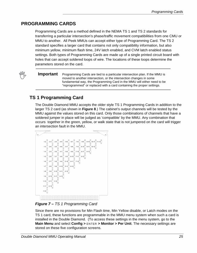
TS 1 Programming Card The Double Diamond MMU accepts the older style TS 1 Programming Cards in addition to the larger TS 2 card (as shown in Figure 8.) The cabinet’s output channels will be tested by the MMU against the values stored on this card. Only those combinations of channels that have a soldered jumper in place will be judged as ‘compatible’ by the MMU. Any combination that occurs together in the green, yellow, or walk state that is not jumpered on the card will trigger an intersection fault in the MMU.
Figure 7 – TS 1 Programming Card
Since there are no provisions for Min Flash time, Min Yellow disable, or Latch modes on the TS 1 card, these functions are programmable in the MMU menu system when such a card is installed in the Double Diamond. (To access these settings in the menu system, go to the Main Menu and select Config > ENTER > Monitor > Per Unit. The necessary settings are stored on these five configuration screens.
Chapter 2 — Double Diamond Hardware
26 Double Diamond MMU Operating Manual
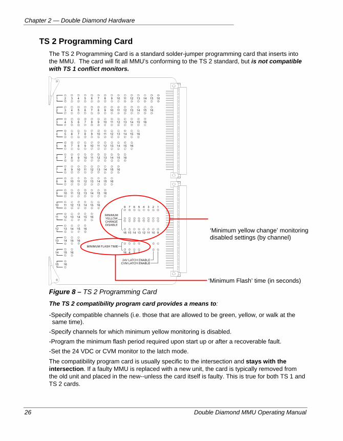
TS 2 Programming Card The TS 2 Programming Card is a standard solder-jumper programming card that inserts into the MMU. The card will fit all MMU’s conforming to the TS 2 standard, but is not compatible with TS 1 conflict monitors.
Figure 8 – TS 2 Programming Card
The TS 2 compatibility program card provides a means to:
-Specify compatible channels (i.e. those that are allowed to be green, yellow, or walk at the same time).
-Specify channels for which minimum yellow monitoring is disabled. -Program the minimum flash period required upon start up or after a recoverable fault. -Set the 24 VDC or CVM monitor to the latch mode. The compatibility program card is usually specific to the intersection and stays with the intersection. If a faulty MMU is replaced with a new unit, the card is typically removed from the old unit and placed in the new--unless the card itself is faulty. This is true for both TS 1 and TS 2 cards.
‘Minimum yellow change’ monitoring disabled settings (by channel)
‘Minimum Flash’ time (in seconds)
Programming Cards
Double Diamond MMU Operating Manual 27
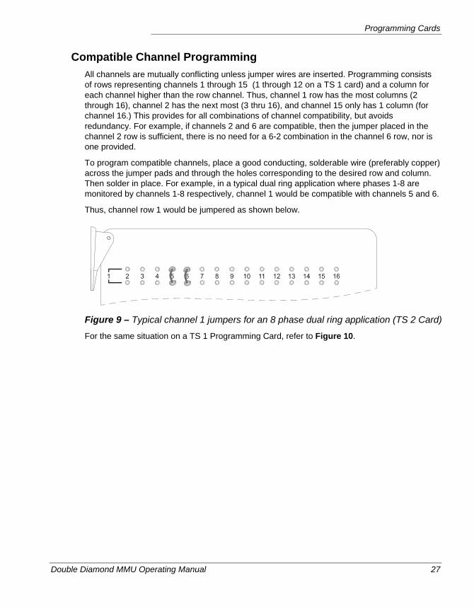
Compatible Channel Programming All channels are mutually conflicting unless jumper wires are inserted. Programming consists of rows representing channels 1 through 15 (1 through 12 on a TS 1 card) and a column for each channel higher than the row channel. Thus, channel 1 row has the most columns (2 through 16), channel 2 has the next most (3 thru 16), and channel 15 only has 1 column (for channel 16.) This provides for all combinations of channel compatibility, but avoids redundancy. For example, if channels 2 and 6 are compatible, then the jumper placed in the channel 2 row is sufficient, there is no need for a 6-2 combination in the channel 6 row, nor is one provided.
To program compatible channels, place a good conducting, solderable wire (preferably copper) across the jumper pads and through the holes corresponding to the desired row and column. Then solder in place. For example, in a typical dual ring application where phases 1-8 are monitored by channels 1-8 respectively, channel 1 would be compatible with channels 5 and 6.
Thus, channel row 1 would be jumpered as shown below.
Figure 9 – Typical channel 1 jumpers for an 8 phase dual ring application (TS 2 Card)
For the same situation on a TS 1 Programming Card, refer to Figure 10.
Chapter 2 — Double Diamond Hardware
28 Double Diamond MMU Operating Manual
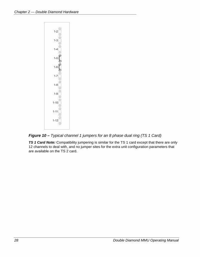
Figure 10 – Typical channel 1 jumpers for an 8 phase dual ring (TS 1 Card)
TS 1 Card Note: Compatibility jumpering is similar for the TS 1 card except that there are only 12 channels to deal with, and no jumper sites for the extra unit configuration parameters that are available on the TS 2 card.
Programming Cards
Double Diamond MMU Operating Manual 29
Ped Jumpers in Type 16 Mode Since there are no walk inputs in the type 16 mode, peds have to be brought in on separate channels. Compatibility jumpers then have to be placed so the peds are able to time with their associated phases. Peds in the type 16 modes are wired to greens. The MMU red input is typically “tied high” (connected to 120 VAC). The MMU yellow wire on the ped channel is typically removed, and the associated terminal is used for the don’t walk output. Don’t walk may or may not be monitored.
Ped Channel Notes 1. Ped channels must have min yellow defeated (by jumper of keyboard) to disable the
requirement that yellow must follow green.
2. The Double Diamond MMU has an option in which ped channels can be made to be display W’s (for walk) instead of G’s (for green). This is a viewing issue only, the physical wiring is strictly to green inputs. It is less confusing, however, to display them as W’s when used as peds. See the set ped channels option programming in section 5.
Compatibility Jumper Cautionary Notes 1. Be sure that the intended jumper is correct (see compatibility checking by the controller on
page 78.) When in place, the MMU will consider those channels compatible--be sure that they indeed should be. Insertion of compatibility jumpers is the responsibility of the person configuring the card.
Be careful to avoid assumptions about phasing and the channel to which the phase is assigned. Phase 1 is not necessarily assigned to channel 1, even though that is usually the case. The assignment of channels to movements tends to be more complex whenever overlap movements are involved (see the next point).
Be careful not to make wrong jumper decisions when overlaps are involved. For example, say phases 1-4 are wired to channels 1-4 respectively and channel 5 is wired to overlap A, which is a 1 + 2 overlap. The jumpers would then be 1-5 and 2-5, but not 1-2 . This is a common mistake made with overlaps. Each of the overlap’s “parent phases” are compatible with the overlap, but the parents are not necessarily compatible with each other.
2. Use good soldering practices to avoid “cold solder joints”. If the soldering iron is not hot enough when the jumper is positioned, the solder may not form a good electrical connection with the pad. This tends to be a common problem with jumper cards.
Chapter 2 — Double Diamond Hardware
30 Double Diamond MMU Operating Manual
PORT 1 GENERAL OPERATION Port 1 allows the controller, the MMU, and other cabinet devices to exchange information. In the case of the controller MMU exchange, the controller can inform the MMU of its output driver configuration. Conversely, upon request, the MMU can inform the controller of its AC field signal status, its compatibility program card configuration, relay status, failure mode condition, etc.
The Port 1 connector provides for a high-speed synchronous channel link and conforms to the Electronics Industry Association standard EIA-485. As a synchronous link, there are both data and clock signals.
The port 1 interface is based on a differential driver/receiver technique. Each data and clock signal has a plus and minus component and it is the difference between them that determines the signal state--not a fixed reference point. This provides high noise immunity
Port 1 is used strictly for inside-the-cabinet communications between the controller, MMU, and BIU’s (Bus Interface Units). It is not used for inter-cabinet or remote data exchange (i.e. not used for communications between one cabinet and another or to a remote communications station). Controller port 3 is the systems port and is used for this purpose.
The cabinet port 1 interface provides a full duplex party line configuration in which the controller unit is the primary station and interfaces to secondary stations, including the MMU (this unit), up to 8 detector stations and up to 8 terminal and facilities (TF) stations via BIU’s.
Port 1 operates at 153.6 Kbaud
The protocol, structure, frames, and information fields within frames are fully defined by the NEMA TS 2 standard. The protocol is based on the IBM SDLC protocol.
Port 1 uses 16 bit CRC error checking for all received frames
Each station is responsible for transmitting frames containing information fields. Frames transmitted by the primary station (the controller) are called command frames, and frames transmitted by secondary stations (such as the MMU) are called response frames. Each command and response frame has a specified type (with a type number). The controller polls all activated secondaries (MMU always activated if port 1 enabled) and issues appropriate command frames for the secondary in question. The secondary responds accordingly.
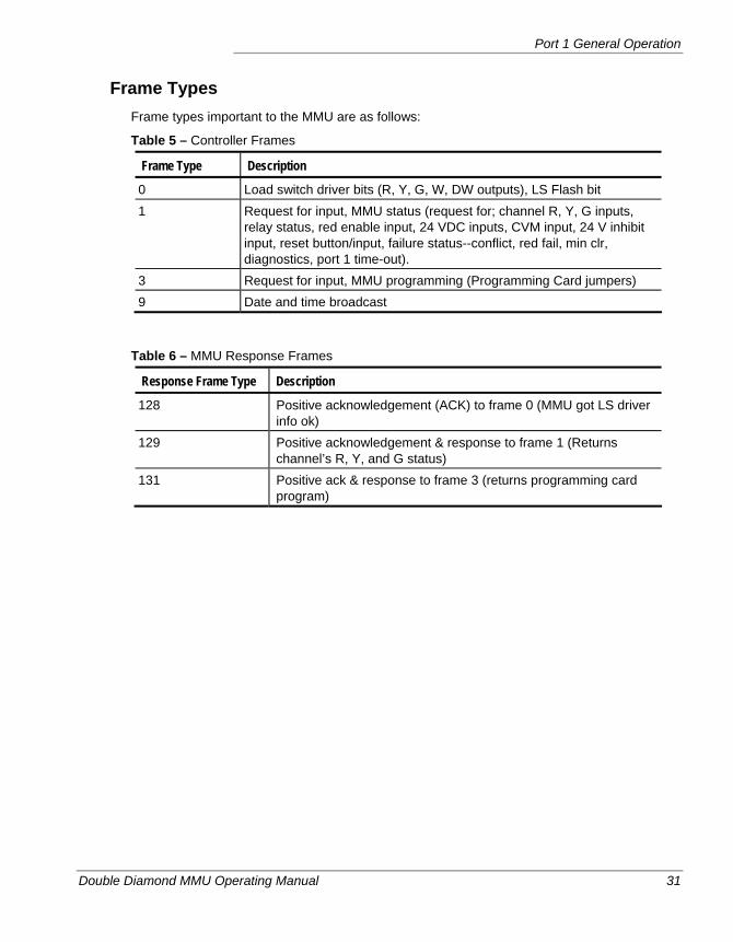
Port 1 General Operation
Double Diamond MMU Operating Manual 31
Frame Types Frame types important to the MMU are as follows:
Table 5 – Controller Frames
Frame Type Description
0 Load switch driver bits (R, Y, G, W, DW outputs), LS Flash bit 1 Request for input, MMU status (request for; channel R, Y, G inputs,
relay status, red enable input, 24 VDC inputs, CVM input, 24 V inhibit input, reset button/input, failure status--conflict, red fail, min clr, diagnostics, port 1 time-out).
3 Request for input, MMU programming (Programming Card jumpers) 9 Date and time broadcast
Table 6 – MMU Response Frames
Response Frame Type Description
128 Positive acknowledgement (ACK) to frame 0 (MMU got LS driver info ok)
129 Positive acknowledgement & response to frame 1 (Returns channel’s R, Y, and G status)
131 Positive ack & response to frame 3 (returns programming card program)
Chapter 2 — Double Diamond Hardware
32 Double Diamond MMU Operating Manual
CONFIGURING THE UNIT FOR ELRA/ELRB/LSM/LNME OPERATION The Double Diamond MMU can be configured so that it is compatible with ELRA, ELRB, LSM, and LNME series monitors. To do this, one needs to modify the DC jumpers located on the back of the front panel circuit board. These four monitoring units were developed prior to the TS 2 standard and utilized what were previously unused Connector A and B pins for their own special functions. These pins now have assignments in the TS 2 standard and therefore must be jumpered to configure the Double Diamond for this previous mode of operation. The standard factory ship mode is TS 2 operation. Refer to page 131 for functional descriptions when this hardware mode is configured.
Caution Do not install a Double Diamond MMU that has been configured like this into
a TS 2 Type 16 wired cabinet. Extreme damage will likely result.
When in TS2 Type 16 mode, MSB Pins T, W, X, and Y are used as channel 13 through 16 red inputs respectively. Although these pins are defined as spares in the TS 1 standard, the TS 1 ELRA/ELRB /LSM/LNME series conflict monitor units used them for special DC level inputs and outputs. Since they are reds in type 16 cabinets, they are likely to be either tied high (to AC+ ) or actually used for AC red signals. In either case, severe damage would result if a Double Diamond MMU configured with DC jumpers (or one of the above TS 1 units themselves) is connected and AC voltages are applied to DC level I/O.
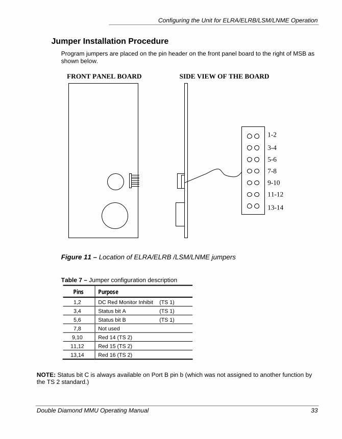
Configuring the Unit for ELRA/ELRB/LSM/LNME Operation
Double Diamond MMU Operating Manual 33
Jumper Installation Procedure Program jumpers are placed on the pin header on the front panel board to the right of MSB as shown below.
Figure 11 – Location of ELRA/ELRB /LSM/LNME jumpers
Table 7 – Jumper configuration description
Pins Purpose 1,2 DC Red Monitor Inhibit (TS 1) 3,4 Status bit A (TS 1) 5,6 Status bit B (TS 1) 7,8 Not used
9,10 Red 14 (TS 2) 11,12 Red 15 (TS 2) 13,14 Red 16 (TS 2)
NOTE: Status bit C is always available on Port B pin b (which was not assigned to another function by the TS 2 standard.)
1-2
3-4
5-6
7-8
9-10
11-12
13-14
FRONT PANEL BOARD SIDE VIEW OF THE BOARD
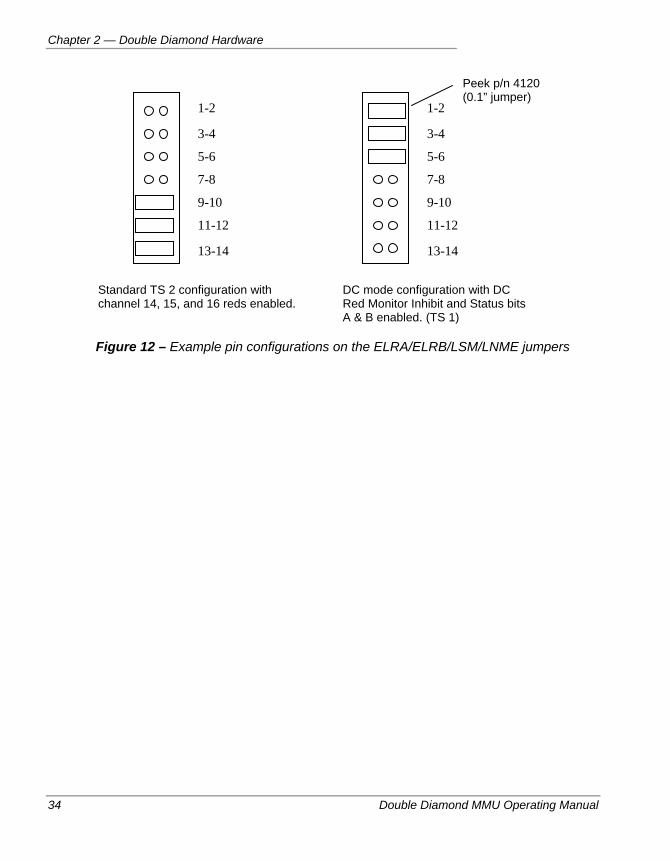
Chapter 2 — Double Diamond Hardware
34 Double Diamond MMU Operating Manual
Figure 12 – Example pin configurations on the ELRA/ELRB/LSM/LNME jumpers
Standard TS 2 configuration with channel 14, 15, and 16 reds enabled.
DC mode configuration with DC Red Monitor Inhibit and Status bits A & B enabled. (TS 1)
1-2
3-4
5-6
7-8
9-10
11-12
13-14
1-2
3-4
5-6
7-8
9-10
11-12
13-14
Peek p/n 4120 (0.1” jumper)
Double Diamond MMU Operating Manual 35
Chapter 3 — Using the Interface
This chapter describes the display interface of the Double Diamond, including the status displays and menus, and how to use the keypad to access them. The following topics are discussed in detail in this chapter:
• General instructions, on page 36.
• Power-up displays, on page 38.
• All of the available status displays are described, starting on page 39.
• The menu system of the Double Diamond, on page 51.
• Setting the date and time is described on page 55.
• Procedures for resetting the unit and exiting flash, on page 56.
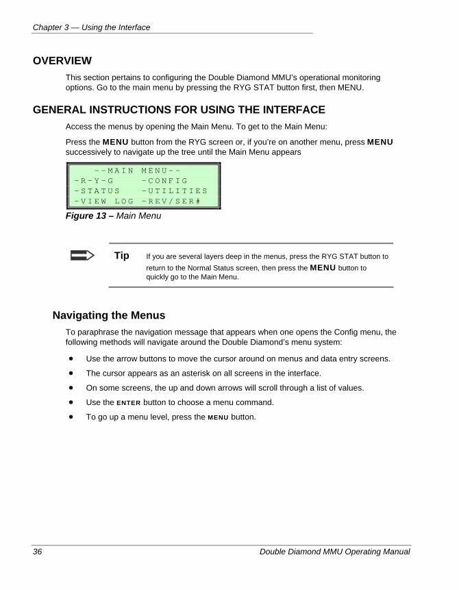
Chapter 3 — Using the Interface
36 Double Diamond MMU Operating Manual
OVERVIEW This section pertains to configuring the Double Diamond MMU’s operational monitoring options. Go to the main menu by pressing the RYG STAT button first, then MENU.
GENERAL INSTRUCTIONS FOR USING THE INTERFACE Access the menus by opening the Main Menu. To get to the Main Menu:
Press the MENU button from the RYG screen or, if you’re on another menu, press MENU successively to navigate up the tree until the Main Menu appears
- - M A I N M E N U - - - R - Y - G - C O N F I G - S T A T U S - U T I L I T I E S - V I E W L O G - R E V / S E R #
Figure 13 – Main Menu
Tip If you are several layers deep in the menus, press the RYG STAT button to return to the Normal Status screen, then press the MENU button to quickly go to the Main Menu.
Navigating the Menus To paraphrase the navigation message that appears when one opens the Config menu, the following methods will navigate around the Double Diamond’s menu system:
Use the arrow buttons to move the cursor around on menus and data entry screens.
The cursor appears as an asterisk on all screens in the interface.
On some screens, the up and down arrows will scroll through a list of values.
Use the ENTER button to choose a menu command.
To go up a menu level, press the MENU button.
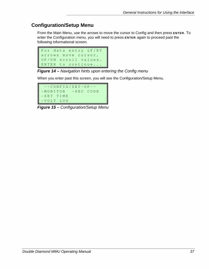
General Instructions for Using the Interface
Double Diamond MMU Operating Manual 37
Configuration/Setup Menu From the Main Menu, use the arrows to move the cursor to Config and then press ENTER. To enter the Configuration menu, you will need to press ENTER again to proceed past the following informational screen.
F o r d a t a e n t r y L F / R T a r r o w s m o v e c u r s o r , U P / D N s c r o l l v a l u e s . E N T E R t o c o n t i n u e . . .
Figure 14 – Navigation hints upon entering the Config menu
When you enter past this screen, you will see the Configuration/Setup Menu.
- - C O N F I G / S E T - U P - - - M O N I T O R - S E C C O D E - S E T T I M E - V O L T L O G
Figure 15 – Configuration/Setup Menu
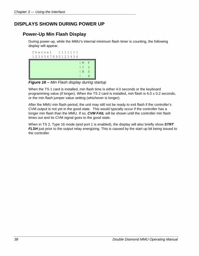
Chapter 3 — Using the Interface
38 Double Diamond MMU Operating Manual
DISPLAYS SHOWN DURING POWER UP
Power-Up Min Flash Display During power-up, while the MMU’s internal minimum flash timer is counting, the following display will appear.
C h a n n e l 1 1 1 1 1 1 1 1 2 3 4 5 6 7 8 9 0 1 2 3 4 5 6
| M F | I L | N S | H
Figure 16 – Min Flash display during startup
When the TS 1 card is installed, min flash time is either 4.0 seconds or the keyboard programming value (if longer). When the TS 2 card is installed, min flash is 6.0 ± 0.2 seconds, or the min flash jumper value setting (whichever is longer).
After the MMU min flash period, the unit may still not be ready to exit flash if the controller’s CVM output is not yet in the good state. This would typically occur if the controller has a longer min flash than the MMU. If so, CVM FAIL will be shown until the controller min flash times out and its CVM signal goes to the good state.
When in TS 2, Type 16 mode (and port 1 is enabled), the display will also briefly show STRT FLSH just prior to the output relay energizing. This is caused by the start up bit being issued to the controller.
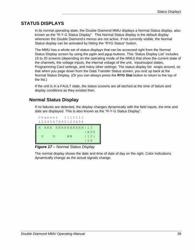
Status Displays
Double Diamond MMU Operating Manual 39
STATUS DISPLAYS In its normal operating state, the Double Diamond MMU displays a Normal Status display, also known as the “R-Y-G Status Display”. This Normal Status display is the default display whenever the Double Diamond’s menus are not active. If not currently visible, the Normal Status display can be activated by hitting the “RYG Status” button.
The MMU has a whole set of status displays that can be accessed right from the Normal Status Display screen by using the pgdn and pgup buttons. This ‘Status Display List’ includes 15 to 20 screens (depending on the operating mode of the MMU) that show the current state of the channels, the voltage inputs, the internal voltage of the unit, input/output states, Programming Card settings, and many other settings. The status display list wraps around, so that when you page down from the Data Transfer Status screen, you end up back at the Normal Status Display. (Or you can always press the RYG Stat button to return to the top of the list.)
If the unit is in a FAULT state, the status screens are all latched at the time of failure and display conditions as they existed then.
Normal Status Display If no failures are detected, the display changes dynamically with the field inputs, the time and date are displayed. This is also known as the “R-Y-G Status Display”.
C h a n n e l 1 1 1 1 1 1 1 1 2 3 4 5 6 7 8 9 0 1 2 3 4 5 6
R R R R R R R R R R R R R R | 1 3 | A U G G G W W | 1 2 : | 5 9
Figure 17 – Normal Status Display
The normal display shows the date and time of date of day on the right. Color indications dynamically change as the actual signals change.
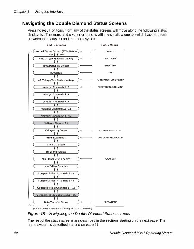
Chapter 3 — Using the Interface
40 Double Diamond MMU Operating Manual
Navigating the Double Diamond Status Screens Pressing PGUP or PGDN from any of the status screens will move along the following status display list. The MENU and RYG STAT buttons will always allow one to switch back and forth between the status list and the menu system.
Status MenusStatus Screens
Normal Status Screen (RYG Status)
Port 1 (Type 0) Status Display
Time/Date/Line Voltage
I/O Status
AC Voltage/Red Enable Voltage
Voltage: Channels 1 - 3
Voltage: Channels 4 - 6
Voltage: Channels 7 - 9
Voltage: Channels 10 - 12
Voltage Log Status
Blink Log Status
Blink ON Status
Blink OFF Status
Min Flash/Latch Enables
Min Yellow Disables
Compatibilities: Channels 1 - 4
Compatibilities: Channels 5 - 8
Compatibilities: Channels 9 - 12
Data Transfer Status
(Shaded items only appear if using TS 2 Type 16 mode)
PGDN PGUP
Voltage: Channels 13 - 15
Voltage: Channel 16
Compatibilities: Channels 13 - 15
“R-Y-G”
“Port1 RYG”
“Date/Time”
“I/O”
“VOLTAGES>LINE/REDN”
“VOLTAGES>SIGNALS”
“VOLTAGES>VOLT LOG”
“VOLTAGES>BLINK LOG”
“COMPAT”
“DATA XFR”
Figure 18 – Navigating the Double Diamond Status screens
The rest of the status screens are described in the sections starting on the next page. The menu system is described starting on page 51.
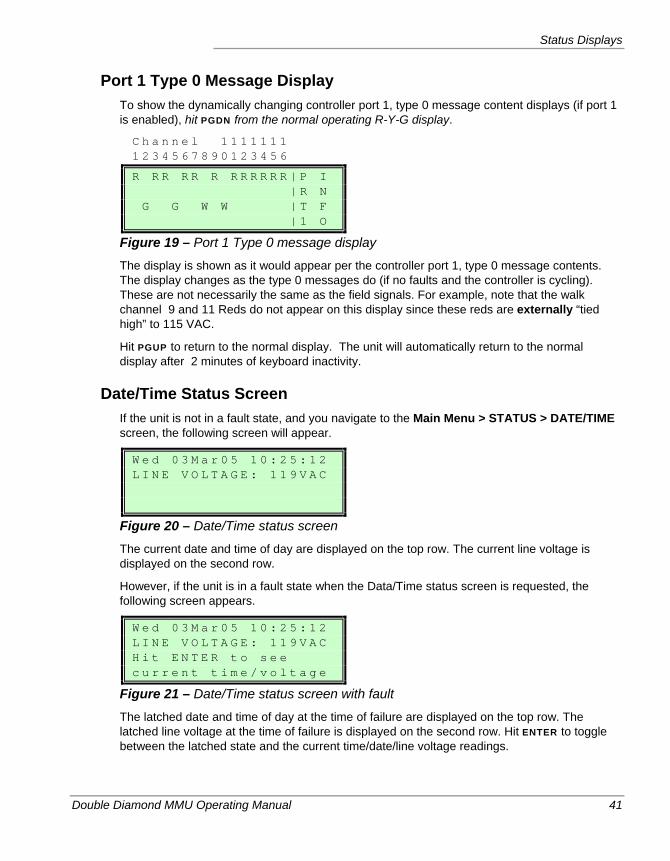
Status Displays
Double Diamond MMU Operating Manual 41
Port 1 Type 0 Message Display To show the dynamically changing controller port 1, type 0 message content displays (if port 1 is enabled), hit PGDN from the normal operating R-Y-G display.
C h a n n e l 1 1 1 1 1 1 1 1 2 3 4 5 6 7 8 9 0 1 2 3 4 5 6
R R R R R R R R R R R R | P I | R N G G W W | T F | 1 O
Figure 19 – Port 1 Type 0 message display
The display is shown as it would appear per the controller port 1, type 0 message contents. The display changes as the type 0 messages do (if no faults and the controller is cycling). These are not necessarily the same as the field signals. For example, note that the walk channel 9 and 11 Reds do not appear on this display since these reds are externally “tied high” to 115 VAC.
Hit PGUP to return to the normal display. The unit will automatically return to the normal display after 2 minutes of keyboard inactivity.
Date/Time Status Screen If the unit is not in a fault state, and you navigate to the Main Menu > STATUS > DATE/TIME screen, the following screen will appear.
W e d 0 3 M a r 0 5 1 0 : 2 5 : 1 2 L I N E V O L T A G E : 1 1 9 V A C
Figure 20 – Date/Time status screen
The current date and time of day are displayed on the top row. The current line voltage is displayed on the second row.
However, if the unit is in a fault state when the Data/Time status screen is requested, the following screen appears.
W e d 0 3 M a r 0 5 1 0 : 2 5 : 1 2 L I N E V O L T A G E : 1 1 9 V A C H i t E N T E R t o s e e c u r r e n t t i m e / v o l t a g e
Figure 21 – Date/Time status screen with fault
The latched date and time of day at the time of failure are displayed on the top row. The latched line voltage at the time of failure is displayed on the second row. Hit ENTER to toggle between the latched state and the current time/date/line voltage readings.
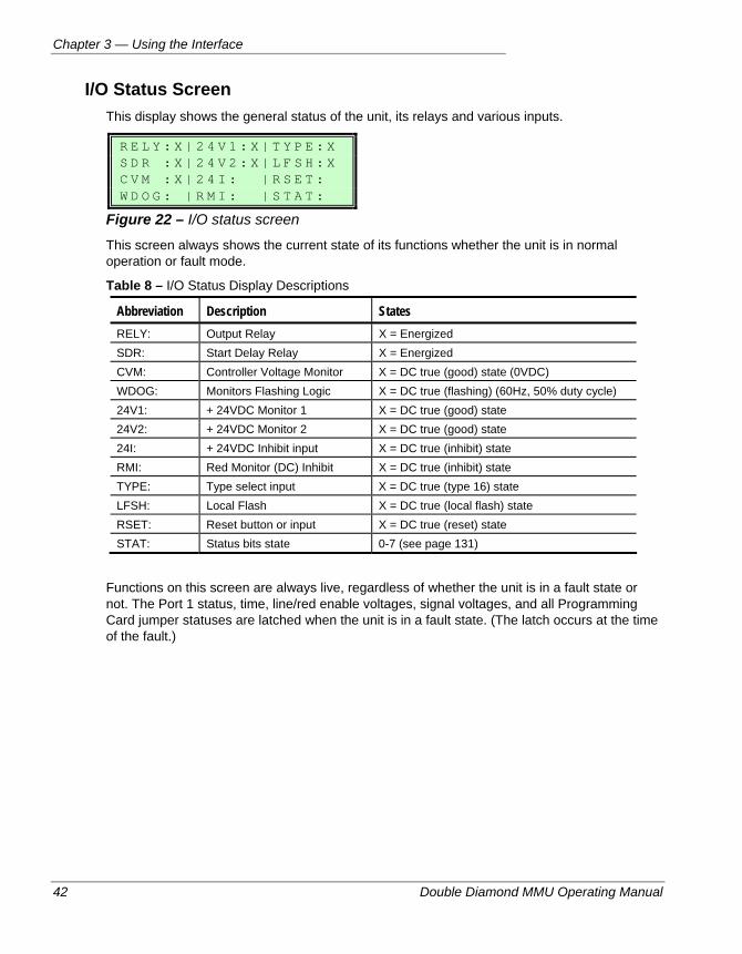
Chapter 3 — Using the Interface
42 Double Diamond MMU Operating Manual
I/O Status Screen This display shows the general status of the unit, its relays and various inputs.
R E L Y : X | 2 4 V 1 : X | T Y P E : X S D R : X | 2 4 V 2 : X | L F S H : X C V M : X | 2 4 I : | R S E T : W D O G : | R M I : | S T A T :
Figure 22 – I/O status screen
This screen always shows the current state of its functions whether the unit is in normal operation or fault mode.
Table 8 – I/O Status Display Descriptions
Abbreviation Description States RELY: Output Relay X = Energized SDR: Start Delay Relay X = Energized CVM: Controller Voltage Monitor X = DC true (good) state (0VDC) WDOG: Monitors Flashing Logic X = DC true (flashing) (60Hz, 50% duty cycle) 24V1: + 24VDC Monitor 1 X = DC true (good) state 24V2: + 24VDC Monitor 2 X = DC true (good) state 24I: + 24VDC Inhibit input X = DC true (inhibit) state RMI: Red Monitor (DC) Inhibit X = DC true (inhibit) state TYPE: Type select input X = DC true (type 16) state LFSH: Local Flash X = DC true (local flash) state RSET: Reset button or input X = DC true (reset) state STAT: Status bits state 0-7 (see page 131)
Functions on this screen are always live, regardless of whether the unit is in a fault state or not. The Port 1 status, time, line/red enable voltages, signal voltages, and all Programming Card jumper statuses are latched when the unit is in a fault state. (The latch occurs at the time of the fault.)
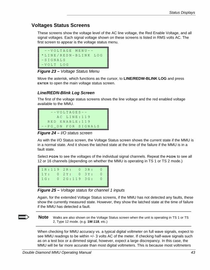
Status Displays
Double Diamond MMU Operating Manual 43
Voltages Status Screens These screens show the voltage level of the AC line voltage, the Red Enable Voltage, and all signal voltages. Each signal voltage shown on these screens is listed in RMS volts AC. The first screen to appear is the voltage status menu.
- - V O L T A G E M E N U - - * L I N E / R E D N - B L I N K L O G - S I G N A L S - V O L T L O G
Figure 23 – Voltage Status Menu
Move the asterisk, which functions as the cursor, to LINE/REDW-BLINK LOG and press ENTER to open the main voltage status screen.
Line/REDN-Blink Log Screen The first of the voltage status screens shows the line voltage and the red enabled voltage available to the MMU.
- - V O L T A G E S - - A C L I N E : 1 1 9 R E D E N A B L E : 1 1 9 - - P G _ D N F O R S I G N A L S
Figure 24 – I/O status screen
As with the I/O Status screen, the Voltage Status screen shows the current state if the MMU is in a normal state. And it shows the latched state at the time of the failure if the MMU is in a fault state.
Select PGDN to see the voltages of the individual signal channels. Repeat the PGDN to see all 12 or 16 channels (depending on whether the MMU is operating in TS 1 or TS 2 mode.)
1 R : 1 1 9 2 R : 0 3 R : 0 1 Y : 0 2 Y : 0 3 Y : 0 1 G : 0 2 G : 1 1 9 3 G : 0
Figure 25 – Voltage status for channel 1 inputs
Again, for the extended Voltage Status screens, if the MMU has not detected any faults, these show the currently measured state. However, they show the latched state at the time of failure if the MMU has detected a fault.
Note Walks are also shown on the Voltage Status screen when the unit is operating in TS 1 or TS 2, Type 12 mode. (e.g. 1W:118, etc.)
When checking for MMU accuracy vs. a typical digital voltmeter on full wave signals, expect to see MMU readings to be within +/- 3 volts AC of the meter. If checking half-wave signals such as on a test box or a dimmed signal, however, expect a large discrepancy. In this case, the MMU will be far more accurate than most digital voltmeters. This is because most voltmeters
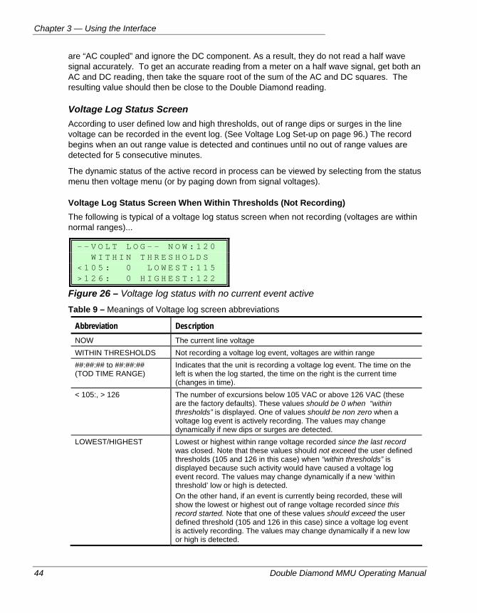
Chapter 3 — Using the Interface
44 Double Diamond MMU Operating Manual
are “AC coupled” and ignore the DC component. As a result, they do not read a half wave signal accurately. To get an accurate reading from a meter on a half wave signal, get both an AC and DC reading, then take the square root of the sum of the AC and DC squares. The resulting value should then be close to the Double Diamond reading.
Voltage Log Status Screen According to user defined low and high thresholds, out of range dips or surges in the line voltage can be recorded in the event log. (See Voltage Log Set-up on page 96.) The record begins when an out range value is detected and continues until no out of range values are detected for 5 consecutive minutes.
The dynamic status of the active record in process can be viewed by selecting from the status menu then voltage menu (or by paging down from signal voltages).
Voltage Log Status Screen When Within Thresholds (Not Recording) The following is typical of a voltage log status screen when not recording (voltages are within normal ranges)...
- - V O L T L O G - - N O W : 1 2 0 W I T H I N T H R E S H O L D S < 1 0 5 : 0 L O W E S T : 1 1 5 > 1 2 6 : 0 H I G H E S T : 1 2 2
Figure 26 – Voltage log status with no current event active Table 9 – Meanings of Voltage log screen abbreviations
Abbreviation Description NOW The current line voltage WITHIN THRESHOLDS Not recording a voltage log event, voltages are within range ##:##:## to ##:##:## (TOD TIME RANGE)
Indicates that the unit is recording a voltage log event. The time on the left is when the log started, the time on the right is the current time (changes in time).
< 105:, > 126 The number of excursions below 105 VAC or above 126 VAC (these are the factory defaults). These values should be 0 when “within thresholds” is displayed. One of values should be non zero when a voltage log event is actively recording. The values may change dynamically if new dips or surges are detected.
LOWEST/HIGHEST Lowest or highest within range voltage recorded since the last record was closed. Note that these values should not exceed the user defined thresholds (105 and 126 in this case) when “within thresholds” is displayed because such activity would have caused a voltage log event record. The values may change dynamically if a new ‘within threshold’ low or high is detected. On the other hand, if an event is currently being recorded, these will show the lowest or highest out of range voltage recorded since this record started. Note that one of these values should exceed the user defined threshold (105 and 126 in this case) since a voltage log event is actively recording. The values may change dynamically if a new low or high is detected.
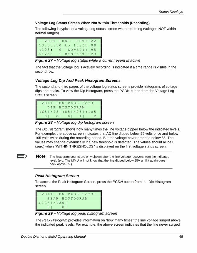
Status Displays
Double Diamond MMU Operating Manual 45
Voltage Log Status Screen When Not Within Thresholds (Recording) The following is typical of a voltage log status screen when recording (voltages NOT within normal ranges)...
- - V O L T L O G - - N O W : 1 2 2 1 3 : 5 3 : 5 0 t o 1 5 : 0 5 : 0 8 < 1 0 5 : 0 L O W E S T : 9 8 > 1 2 6 : 1 H I G H E S T : 1 2 3
Figure 27 – Voltage log status while a current event is active
The fact that the voltage log is actively recording is indicated if a time range is visible in the second row.
Voltage Log Dip And Peak Histogram Screens The second and third pages of the voltage log status screens provide histograms of voltage dips and peaks. To view the Dip Histogram, press the PGDN button from the Voltage Log Status screen.
- V O L T L O G : P A G E 2 o f 3 - D I P H I S T O G R A M < 6 5 | < 7 5 | < 8 5 | < 9 5 | < 1 0 5 0 | 0 | 0 | 1 | 2
Figure 28 – Voltage log dip histogram screen
The Dip Histogram shows how many times the line voltage dipped below the indicated levels. For example, the above screen indicates that AC line dipped below 95 volts once and below 105 volts twice during the recording period. But the voltage never dropped below 85. The values may change dynamically if a new threshold is detected. The values should all be 0 (zero) when “WITHIN THRESHOLDS” is displayed on the first voltage status screen.
Note The histogram counts are only shown after the line voltage recovers from the indicated level. (e.g. The MMU will not know that the line dipped below 85V until it again goes back above 85.)
Peak Histogram Screen To access the Peak Histogram Screen, press the PGDN button from the Dip Histogram screen.
- V O L T L O G : P A G E 3 o f 3 - P E A K H I S T O G R A M > 1 2 5 | > 1 3 0 | 0 | 0 |
Figure 29 – Voltage log peak histogram screen
The Peak Histogram provides information on “how many times” the line voltage surged above the indicated peak levels. For example, the above screen indicates that the line never surged
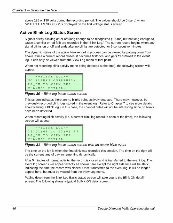
Chapter 3 — Using the Interface
46 Double Diamond MMU Operating Manual
above 125 or 130 volts during the recording period. The values should be 0 (zero) when “WITHIN THRESHOLDS” is displayed on the first voltage status screen.
Active Blink Log Status Screen Signals briefly blinking on or off (long enough to be recognized (100ms) but not long enough to cause a conflict or red fail) are recorded in the “Blink Log.” The current record begins when any signal blinks on or off and ends after no blinks are detected for 5 consecutive minutes.
The dynamic status of the active blink record in process can be viewed by paging down from above. Once a current record closes, it becomes historical and gets transferred to the event log. It can only be viewed from the View Log menu at that point.
When not recording blink activity (none being detected at the time), the following screen will appear.
- - B L I N K L O G - - N O B L I N K S C U R R E N T L Y . P G _ D N T O V I E W P E R C H A N N E L D E T A I L .
Figure 30 – Blink log basic status screen
This screen indicates there are no blinks being actively detected. There may, however, be previously recorded blink logs stored in the event log. (Refer to Chapter 7 to see more details about viewing a Blink log.) In this case, the channel detail will not be interesting since no blinks have been detected.
When recording blink activity (i.e. a current blink log record is open at the time), the following screen will appear.
- - B L I N K L O G - - 1 2 : 0 1 : 0 6 t o 1 2 : 0 3 : 1 8 P G _ D N T O V I E W P E R C H A N N E L D E T A I L .
Figure 31 – Blink log basic status screen with an active blink event
The time on the left is when the first blink was recorded this session. The time on the right will be the current time of day incrementing dynamically.
After 5 minutes of normal activity, the record is closed and is transferred to the event log. The event log screens will appear exactly as shown here except the right side time will be static, indicating the time the record was closed. Once transferred to the event log, it will no longer appear here, but must be viewed from the View Log menu.
Paging down from the Blink Log Basic status screen will take you to the Blink ON detail screen. The following shows a typical BLINK ON detail screen.
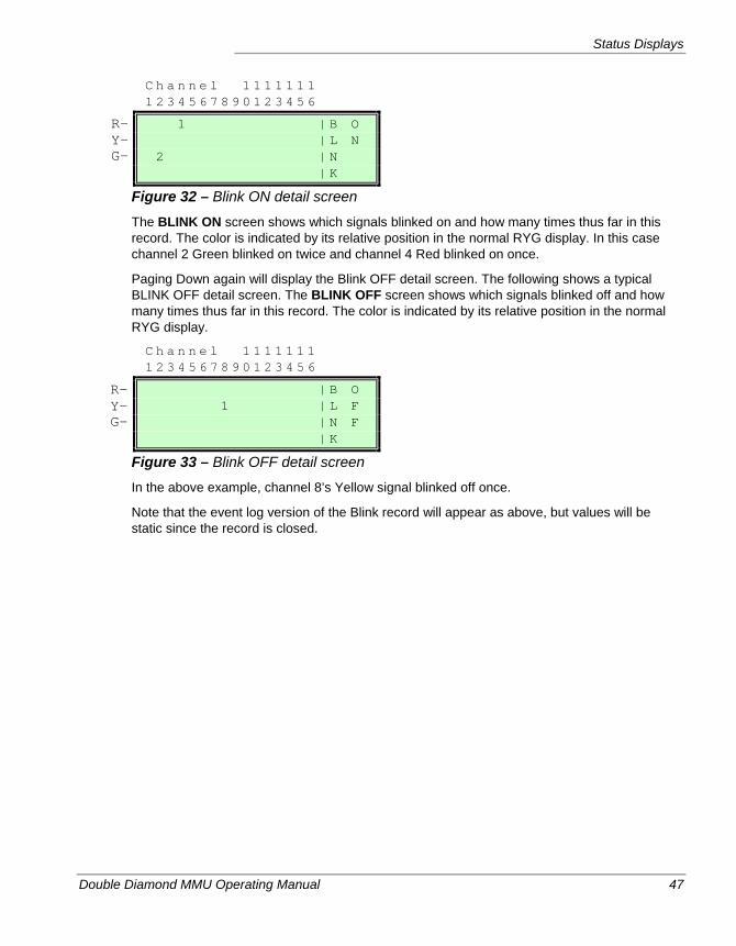
Status Displays
Double Diamond MMU Operating Manual 47
C h a n n e l 1 1 1 1 1 1 1 1 2 3 4 5 6 7 8 9 0 1 2 3 4 5 6
1 | B O | L N 2 | N | K
Figure 32 – Blink ON detail screen
The BLINK ON screen shows which signals blinked on and how many times thus far in this record. The color is indicated by its relative position in the normal RYG display. In this case channel 2 Green blinked on twice and channel 4 Red blinked on once.
Paging Down again will display the Blink OFF detail screen. The following shows a typical BLINK OFF detail screen. The BLINK OFF screen shows which signals blinked off and how many times thus far in this record. The color is indicated by its relative position in the normal RYG display.
C h a n n e l 1 1 1 1 1 1 1 1 2 3 4 5 6 7 8 9 0 1 2 3 4 5 6
| B O 1 | L F | N F | K
Figure 33 – Blink OFF detail screen
In the above example, channel 8’s Yellow signal blinked off once.
Note that the event log version of the Blink record will appear as above, but values will be static since the record is closed.
R- Y- G-
R- Y- G-
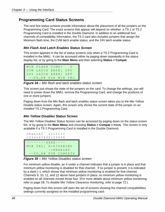
Chapter 3 — Using the Interface
48 Double Diamond MMU Operating Manual
Programming Card Status Screens The next few status screens provide information about the placement of all the jumpers on the Programming Card. The exact screens that appear will depend on whether a TS 1 or TS 2 Programming Card is installed in the Double Diamond. In addition to an additional four channels of compatibility information, the TS 2 card also includes jumpers that assign the Minimum flash time, the CVM latch enable status, and the 24V latch enable status.
Min Flash And Latch Enables Status Screen This screen appears in the list of status screens only when a TS 2 Programming Card is installed in the MMU. It can be accessed either by paging down repeatedly in the status display list, or by going to the Main Menu and then selecting Status > Compat.
M I N F L A S H T I M E : 6 C V M L A T C H E N A B : O F F 2 4 V L A T C H E N A B : O F F - - P G _ D N F O R M I N Y E L
Figure 34 – Min flash and latch enables status screen
This screen just shows the state of the jumpers on the card. To change the settings, you will need to power down the MMU, remove the Programming Card, and change the positions of one or more jumpers.
Paging down from the Min flash and latch enables status screen takes you to the Min Yellow Disable status screen. Again, this screen only shows the current state of the jumper on an installed TS 2 Programming Card.
Min Yellow Disables Status Screen The Min Yellow Disables Status Screen can be accessed by paging down on the status screen list, or by going to the Main Menu and choosing Status > Compat > PGDN. This screen is only available if a TS 2 Programming Card is installed in the Double Diamond.
C h a n n e l 1 1 1 1 1 1 1 1 2 3 4 5 6 7 8 9 0 1 2 3 4 5 6
- - - - - - - - X X X X - - - - M I N Y E L : X = D I S A B L E D - = E N A B L E D - - P G _ D N F O R C O M P A T S
Figure 35 – Min Yellow Disables status screen
For minimum yellow disable, an X under a channel indicates that a jumper is in place and that minimum yellow monitoring is disabled for that channel. If no jumper is present, it is indicated by a dash (–), which shows that minimum yellow monitoring is enabled for that channel. Channels 9, 10, 11, and 12 above have jumpers in place, so minimum yellow monitoring is enabled on all channels except those four. (For more details about minimum yellow monitoring, refer to page 59. To disable Min Yellow Clearance monitoring, refer to page 72.)
Paging down from this screen will open the set of screens showing the channel compatibilities settings currently assigned on the installed programming card.
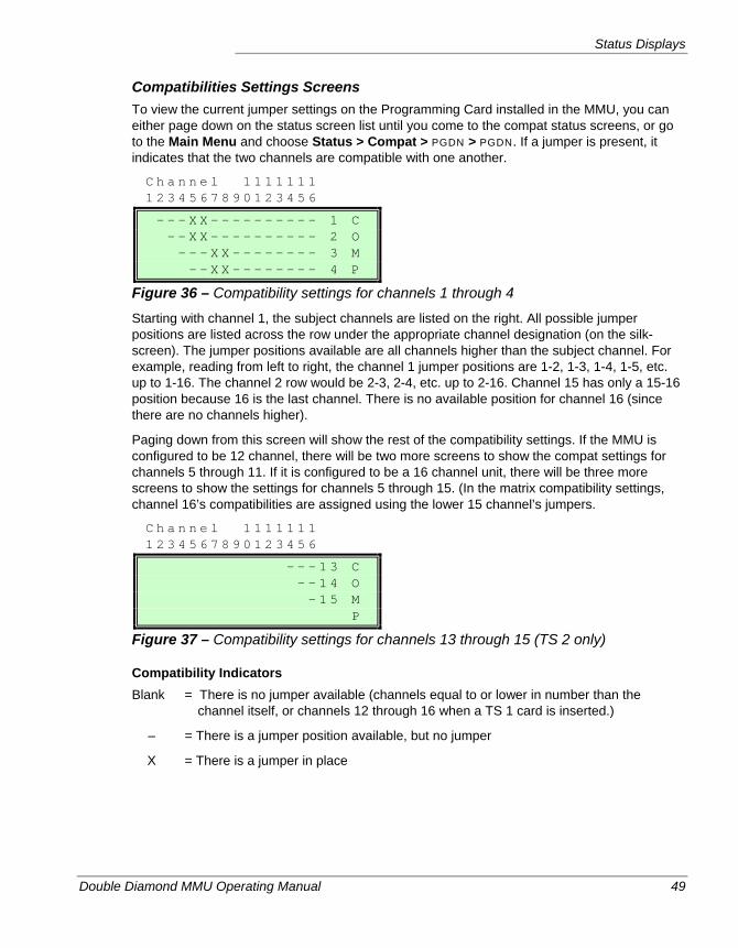
Status Displays
Double Diamond MMU Operating Manual 49
Compatibilities Settings Screens To view the current jumper settings on the Programming Card installed in the MMU, you can either page down on the status screen list until you come to the compat status screens, or go to the Main Menu and choose Status > Compat > PGDN > PGDN. If a jumper is present, it indicates that the two channels are compatible with one another.
C h a n n e l 1 1 1 1 1 1 1 1 2 3 4 5 6 7 8 9 0 1 2 3 4 5 6
- - - X X - - - - - - - - - - 1 C - - X X - - - - - - - - - - 2 O - - - X X - - - - - - - - 3 M - - X X - - - - - - - - 4 P
Figure 36 – Compatibility settings for channels 1 through 4
Starting with channel 1, the subject channels are listed on the right. All possible jumper positions are listed across the row under the appropriate channel designation (on the silk-screen). The jumper positions available are all channels higher than the subject channel. For example, reading from left to right, the channel 1 jumper positions are 1-2, 1-3, 1-4, 1-5, etc. up to 1-16. The channel 2 row would be 2-3, 2-4, etc. up to 2-16. Channel 15 has only a 15-16 position because 16 is the last channel. There is no available position for channel 16 (since there are no channels higher).
Paging down from this screen will show the rest of the compatibility settings. If the MMU is configured to be 12 channel, there will be two more screens to show the compat settings for channels 5 through 11. If it is configured to be a 16 channel unit, there will be three more screens to show the settings for channels 5 through 15. (In the matrix compatibility settings, channel 16’s compatibilities are assigned using the lower 15 channel’s jumpers.
C h a n n e l 1 1 1 1 1 1 1 1 2 3 4 5 6 7 8 9 0 1 2 3 4 5 6
- - - 1 3 C - - 1 4 O - 1 5 M P
Figure 37 – Compatibility settings for channels 13 through 15 (TS 2 only)
Compatibility Indicators Blank = There is no jumper available (channels equal to or lower in number than the
channel itself, or channels 12 through 16 when a TS 1 card is inserted.)
– = There is a jumper position available, but no jumper
X = There is a jumper in place
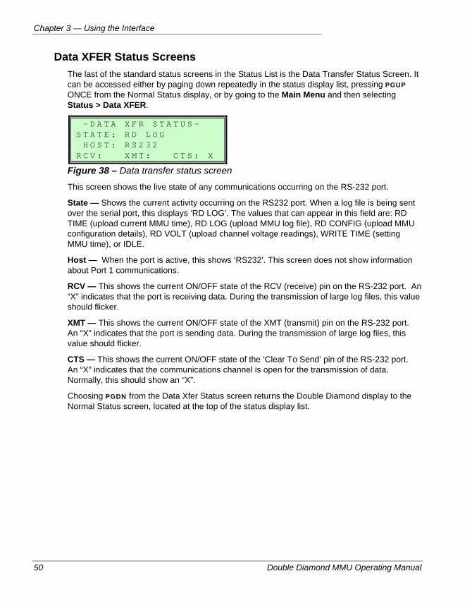
Chapter 3 — Using the Interface
50 Double Diamond MMU Operating Manual
Data XFER Status Screens The last of the standard status screens in the Status List is the Data Transfer Status Screen. It can be accessed either by paging down repeatedly in the status display list, pressing PGUP ONCE from the Normal Status display, or by going to the Main Menu and then selecting Status > Data XFER.
- D A T A X F R S T A T U S - S T A T E : R D L O G H O S T : R S 2 3 2 R C V : X M T : C T S : X
Figure 38 – Data transfer status screen
This screen shows the live state of any communications occurring on the RS-232 port.
State — Shows the current activity occurring on the RS232 port. When a log file is being sent over the serial port, this displays ‘RD LOG’. The values that can appear in this field are: RD TIME (upload current MMU time), RD LOG (upload MMU log file), RD CONFIG (upload MMU configuration details), RD VOLT (upload channel voltage readings), WRITE TIME (setting MMU time), or IDLE.
Host — When the port is active, this shows ‘RS232’. This screen does not show information about Port 1 communications.
RCV — This shows the current ON/OFF state of the RCV (receive) pin on the RS-232 port. An “X” indicates that the port is receiving data. During the transmission of large log files, this value should flicker.
XMT — This shows the current ON/OFF state of the XMT (transmit) pin on the RS-232 port. An “X” indicates that the port is sending data. During the transmission of large log files, this value should flicker.
CTS — This shows the current ON/OFF state of the ‘Clear To Send’ pin of the RS-232 port. An “X” indicates that the communications channel is open for the transmission of data. Normally, this should show an “X”.
Choosing PGDN from the Data Xfer Status screen returns the Double Diamond display to the Normal Status screen, located at the top of the status display list.
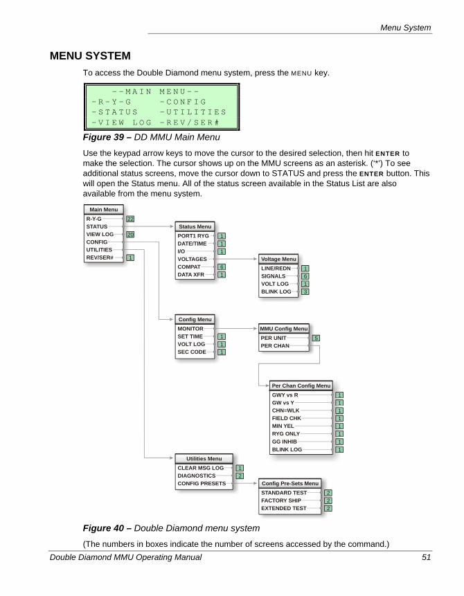
Menu System
Double Diamond MMU Operating Manual 51
MENU SYSTEM To access the Double Diamond menu system, press the MENU key.
- - M A I N M E N U - - - R - Y - G - C O N F I G - S T A T U S - U T I L I T I E S - V I E W L O G - R E V / S E R #
Figure 39 – DD MMU Main Menu
Use the keypad arrow keys to move the cursor to the desired selection, then hit ENTER to make the selection. The cursor shows up on the MMU screens as an asterisk. (‘*’) To see additional status screens, move the cursor down to STATUS and press the ENTER button. This will open the Status menu. All of the status screen available in the Status List are also available from the menu system.
Main Menu
Per Chan Config Menu
Status Menu
Config Menu
Utilities Menu
Config Pre-Sets Menu
Voltage Menu
MMU Config Menu
R-Y-G
GWY vs R
PORT1 RYG
MONITOR
CLEAR MSG LOG
STANDARD TEST
LINE/REDN
PER UNIT
STATUS
GW vs Y
DATE/TIME
SET TIME
DIAGNOSTICS
FACTORY SHIP
SIGNALS
PER CHAN
VIEW LOG
CHN=WLK
I/O
VOLT LOG
CONFIG PRESETS
EXTENDED TEST
VOLT LOG
CONFIG
FIELD CHK
VOLTAGES
SEC CODE
BLINK LOG
UTILITIES
MIN YEL
COMPATREV/SER#
RYG ONLYGG INHIBBLINK LOG
DATA XFR
22
11
1
1
1
1
1
1
2
2
1
5
6
20
1
1
1
1
2
2
6
13
1
111
1
Figure 40 – Double Diamond menu system
(The numbers in boxes indicate the number of screens accessed by the command.)
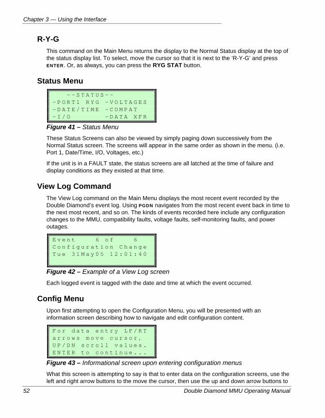
Chapter 3 — Using the Interface
52 Double Diamond MMU Operating Manual
R-Y-G This command on the Main Menu returns the display to the Normal Status display at the top of the status display list. To select, move the cursor so that it is next to the ‘R-Y-G’ and press ENTER. Or, as always, you can press the RYG STAT button.
Status Menu - - S T A T U S - - - P O R T 1 R Y G - V O L T A G E S - D A T E / T I M E - C O M P A T - I / O - D A T A X F R
Figure 41 – Status Menu
These Status Screens can also be viewed by simply paging down successively from the Normal Status screen. The screens will appear in the same order as shown in the menu. (i.e. Port 1, Date/Time, I/O, Voltages, etc.)
If the unit is in a FAULT state, the status screens are all latched at the time of failure and display conditions as they existed at that time.
View Log Command The View Log command on the Main Menu displays the most recent event recorded by the Double Diamond’s event log. Using PGDN navigates from the most recent event back in time to the next most recent, and so on. The kinds of events recorded here include any configuration changes to the MMU, compatibility faults, voltage faults, self-monitoring faults, and power outages.
E v e n t 6 o f 6 C o n f i g u r a t i o n C h a n g e T u e 3 1 M a y 0 5 1 2 : 0 1 : 4 0
Figure 42 – Example of a View Log screen
Each logged event is tagged with the date and time at which the event occurred.
Config Menu Upon first attempting to open the Configuration Menu, you will be presented with an information screen describing how to navigate and edit configuration content.
F o r d a t a e n t r y L F / R T a r r o w s m o v e c u r s o r , U P / D N s c r o l l v a l u e s . E N T E R t o c o n t i n u e . . .
Figure 43 – Informational screen upon entering configuration menus
What this screen is attempting to say is that to enter data on the configuration screens, use the left and right arrow buttons to the move the cursor, then use the up and down arrow buttons to
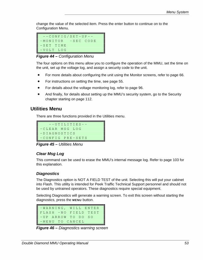
Menu System
Double Diamond MMU Operating Manual 53
change the value of the selected item. Press the enter button to continue on to the Configuration Menu.
- - C O N F I G / S E T - U P - - - M O N I T O R - S E C C O D E - S E T T I M E - V O L T L O G
Figure 44 – Configuration Menu
The four options on this menu allow you to configure the operation of the MMU, set the time on the unit, set up the voltage log, and assign a security code to the unit.
For more details about configuring the unit using the Monitor screens, refer to page 66.
For instructions on setting the time, see page 55.
For details about the voltage monitoring log, refer to page 96.
And finally, for details about setting up the MMU’s security system, go to the Security chapter starting on page 112.
Utilities Menu There are three functions provided in the Utilities menu.
- - U T I L I T I E S - - - C L E A R M S G L O G - D I A G N O S T I C S - C O N F I G P R E - S E T S
Figure 45 – Utilities Menu
Clear Msg Log This command can be used to erase the MMU’s internal message log. Refer to page 103 for this explanation.
Diagnostics The Diagnostics option is NOT A FIELD TEST of the unit. Selecting this will put your cabinet into Flash. This utility is intended for Peek Traffic Technical Support personnel and should not be used by untrained operators. These diagnostics require special equipment.
Selecting Diagnostics will generate a warning screen. To exit this screen without starting the diagnostics, press the MENU button.
- W A R N I N G , W I L L E N T E R F L A S H - N O F I E L D T E S T - U P A R R O W T O D O S O - M E N U T O C A N C E L
Figure 46 – Diagnostics warning screen
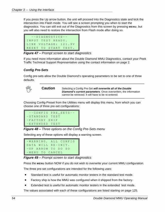
Chapter 3 — Using the Interface
54 Double Diamond MMU Operating Manual
If you press the Up arrow button, the unit will proceed into the Diagnostics state and kick the intersection into Flash mode. You will see a screen prompting you when to start the diagnostics. You can still exit out of the Diagnostics from this screen by pressing MENU, but you will also need to restore the intersection from Flash mode after doing so.
- - D I A G N O S T I C S - - I N P U T T E S T R E A D Y . L I N E V O L T A G E : 1 2 1 . 9 V R E S E T T O S T A R T T E S T .
Figure 47 – Prompt screen to start diagnostics
If you need more information about the Double Diamond MMU Diagnostics, contact your Peek Traffic Technical Support Representative using the contact information on page 2.
Config Pre-Sets
Config pre-sets allow the Double Diamond’s operating parameters to be set to one of three defaults.
Caution Selecting a Config Pre-Set will overwrite all of the Double
Diamond’s current parameters. Once overwritten, the information cannot be retrieved. It will have to be re-entered.
Choosing Config-Preset from the Utilities menu will display this menu, from which you can choose one of three pre-set configurations:
- - C O N F I G P R E _ S E T S - - - S T A N D A R D T E S T - F A C T O R Y S H I P - E X T E N D E D T E S T
Figure 48 – Three options on the Config Pre-Sets menu
Selecting any of these options will display a warning screen.
- W A R N I N G , A L L C O N F I G D A T A W I L L R E - I N I T . - U P A R R O W T O D O S O - M E N U T O C A N C E L
Figure 49 – Prompt screen to start diagnostics
Press the MENU button NOW if you do not wish to overwrite your current MMU configuration.
The three pre-set configurations are intended for the following uses:
Standard test is useful for automatic monitor testers in the standard test mode.
Factory ship is how the MMU was configured when it shipped from the factory.
Extended test is useful for automatic monitor testers in the extended test mode.
The values associated with each of these configurations are listed starting on page 125.
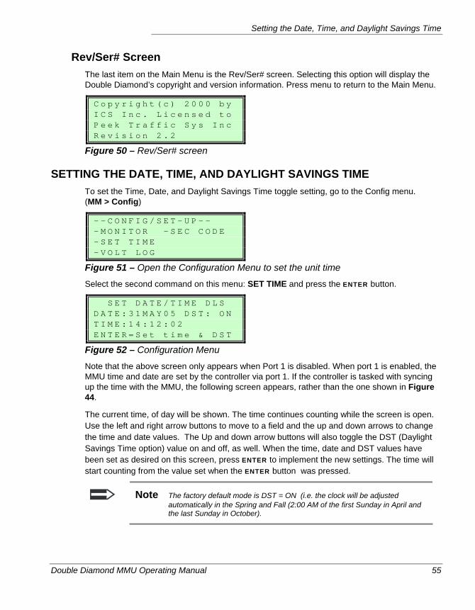
Setting the Date, Time, and Daylight Savings Time
Double Diamond MMU Operating Manual 55
Rev/Ser# Screen The last item on the Main Menu is the Rev/Ser# screen. Selecting this option will display the Double Diamond’s copyright and version information. Press menu to return to the Main Menu.
C o p y r i g h t ( c ) 2 0 0 0 b y I C S I n c . L i c e n s e d t o P e e k T r a f f i c S y s I n c R e v i s i o n 2 . 2
Figure 50 – Rev/Ser# screen
SETTING THE DATE, TIME, AND DAYLIGHT SAVINGS TIME To set the Time, Date, and Daylight Savings Time toggle setting, go to the Config menu. (MM > Config)
- - C O N F I G / S E T - U P - - - M O N I T O R - S E C C O D E - S E T T I M E - V O L T L O G
Figure 51 – Open the Configuration Menu to set the unit time
Select the second command on this menu: SET TIME and press the ENTER button.
S E T D A T E / T I M E D L S D A T E : 3 1 M A Y 0 5 D S T : O N T I M E : 1 4 : 1 2 : 0 2 E N T E R = S e t t i m e & D S T
Figure 52 – Configuration Menu
Note that the above screen only appears when Port 1 is disabled. When port 1 is enabled, the MMU time and date are set by the controller via port 1. If the controller is tasked with syncing up the time with the MMU, the following screen appears, rather than the one shown in Figure 44.
The current time, of day will be shown. The time continues counting while the screen is open. Use the left and right arrow buttons to move to a field and the up and down arrows to change the time and date values. The Up and down arrow buttons will also toggle the DST (Daylight Savings Time option) value on and off, as well. When the time, date and DST values have been set as desired on this screen, press ENTER to implement the new settings. The time will start counting from the value set when the ENTER button was pressed.
Note The factory default mode is DST = ON (i.e. the clock will be adjusted automatically in the Spring and Fall (2:00 AM of the first Sunday in April and the last Sunday in October).
Chapter 3 — Using the Interface
56 Double Diamond MMU Operating Manual
PROCEDURES FOR RESETTING AND EXITING FLASH
Arbitrarily resetting a field controller from an improper interval can be hazardous. For example, it is improper to reset from flashing amber on main street to cross street green. Keep in mind that stop time is applied to the controller at the time of fault occurrence and it may have stopped in any interval. Steps should be taken to “re-initialize” properly as indicated below.
1. Before resetting, if there is a cabinet switch that does not also apply external start to the controller, place that switch in the flash position first. This prevents inadvertent exit from flash. If the flash switch also applies external start, and that is the only switch available, do not place it in the flash position until after the controller has been evaluated.
2. Still before resetting, evaluate the MMU, controller, and Load switches to determine the cause of the failure. Once the controller has been evaluated (displays, etc.), if not already done, place the flash switch in the flash position regardless of whether external start is applied or not. Make replacements and/or repairs as necessary.
Important Things to Remember When Resetting Your agency may have specific intersection reset procedures. Defer to those, if available.
Some cabinets may be provided with a pulse circuit to automatically re-initialize the controller. Those TS 2 controllers responding to Port 1 (as described in Reset Note 3 on page 23) will automatically re-initialize after reset.
Finally, the MMU has a feature called Fault Re-initialize, which also automatically re-initializes the controller after reset when enabled.
Double Diamond MMU Operating Manual 57
Chapter 4 — Controller Output Fault Monitoring
This chapter introduces and explains the controller output monitoring capabilities of the Double Diamond MMU. The following topics are discussed in detail in this chapter:
• The types of controller outputs that are monitored, on page 58.
• Displays used to indicate output faults, on page 62.
• Configuring the MMU for output monitoring, on page 66.
• A description of the electrical connections and concerns of output monitoring, on page 75.
Chapter 4 — Controller Output Fault Monitoring
58 Double Diamond MMU Operating Manual
OVERVIEW OF OUTPUT MONITORING The following topics describe the variety of controller outputs and output combinations that can be monitored by the Double Diamond MMU.
Conflict Monitoring A conflict occurs when any combination of Green, Yellow, or Walk (GYW) inputs are active on two or more non-compatible channels for a specified period. A pair of ‘non-compatible’ channels are two channels which do not have a jumper installed on the MMU’s Programming Card. (Refer to page 25 for details about the Programming Cards.)
Conflict Recognition Time — The time to recognize a conflict is 325 +/- 125 milliseconds in the standard mode. This is the minimum time required for G, Y, Walk signals to be in a conflicting state before they will be registered as a conflict and the output relay trips. Thus, G, Y, W signals conflicting less than 200 milliseconds must not cause a conflict and G, Y, W signals conflicting for more than 450 milliseconds must cause a conflict. An option called ‘Fast Flash’ can be turned on to lower this conflict recognition time to approximately 150 milliseconds for Canadian intersections.
Green, Yellow, Walk Signal Thresholds — The MMU expects signals to be at least 20 +/- 5 VAC (RMS) when ON. Therefore, Green, Yellow, and Walk signals of less than 15 volts AC must be considered “OFF” and signals above 25 volts AC must be considered “ON”. Signals from 15 to 25 may be considered either OFF or ON.
Red Signal Threshold — The MMU expects the red signal on a channel to show at least 60 +/-10 VAC (RMS) when ON. Thus, a channel’s Red signal of less than 50 volts AC must be considered “OFF” and a red signal above 70 volts AC must be considered “ON”. A red signal from 50 to 70 may be considered either OFF or ON.
Red Failure Monitoring Red failure occurs whenever all signals are absent (below threshold) on a channel for a specified period. In other words, each channel must have at least one R, Y, G (or walk in TS 1 or type 12 modes) input above threshold at all times. “Red failure” is a familiar term, but often misinterpreted. A better term would be “signal loss” because absence of any signal can cause the failure. For example, if a load switch fails to display green when it should, then a “red failure” will occur, even though the green driver is at fault (and the red driver may be fine). Regardless of appropriateness, “Red Fail” is the term used.
Red Fail Recognition Time — The minimum Red Fail recognition time is 850 +/- 125 milliseconds. This is the minimum time all the signals must be absent (below threshold) on a channel to cause a Red Failure.
Red Enable Input — Red failure monitoring is only executed when the AC Red Enable input is active (120 VAC). Red Enable is usually controlled by the cabinet signal bus system so that red monitoring only occurs during automatic operation and not in flash or when signals are off (see Red Enable Input Control, page 76).
Red fail, RYG Only Option — This option is only available in the true TS 1 or type 12 modes. This keyboard option removes walk from the red fail determination in these modes. When
Overview of Output Monitoring
Double Diamond MMU Operating Manual 59
enabled, walk alone on a channel cannot prevent a red failure from occurring. This option does not pertain to type 16 operation because Type 16 mode uses no walk inputs.
Tying unused and no-red channels high — Since all channels must have at least one signal active at all times, the red input of all unused monitor channels must be tied high (to 120 VAC.) Red is the obvious choice because it does not cause conflicts. Red may also be tied high for peds and 5 section head left turns because they have no red signal (FDW is usually not considered as “red” and is usually not monitored, although may be in some cases).
No Yellow, Min Yellow And Clearance Monitoring These monitoring states all pertain to the duration of the yellow signal on a channel.
No Yellow Failure A No Yellow Failure will occur if no yellow comes on after green. Yellow must follow a green that has been on for 260 ms or more. No yellow monitoring is enabled only when the red enable input is active (120 VAC). There is also a keyboard option when the TS 1 card is installed, or a jumper option on the card when the TS 2 card is installed which permanently disables all yellow monitoring on a per channel basis.
Short Yellow Failure A Short Yellow Fail (minimum yellow change) will occur if yellow comes on, but is too short. Yellow must be greater than 2.7 seconds in duration. Short yellow monitoring is enabled only when the red enable input is active (120 VAC). There is also a keyboard option when the TS 1 card is installed, or a jumper option on the card when the TS 2 card is installed which permanently disables all yellow monitoring on a per channel basis.
Clearance Failure In the Double Diamond, a ‘Clearance Failure’ is the same thing as a ‘Green to conflicting green inhibit’ failure. A Clearance Failure will occur any time the signal sequence goes from a green to a conflicting green in less than 2.7 seconds. Clearance failure will occur regardless of whether yellow monitoring is enabled or disabled or whether a yellow occurs or not. Clearance failure monitoring is enabled only when the red enable input is active (120 VAC). This setting is configured in the ‘Per Channel’ monitoring configuration screens, under ‘GG INHIB’. See page 74 for details.
Multiple Indications Monitoring To use this monitoring mode, it will need to be programmed into the MMU’s interface. It cannot be defined on the Programming Card. With this type of monitoring, a Multiple Indications failure occurs if certain combinations of signals are active on the same channel. There are two types of “MULT-IND” failure and they can be activated/deactivated independently in the ‘Per Channel’ section of the Monitor menu.
Per Channel G or W vs. Yellow Monitoring When enabled on a channel (via the MMU’s Per Chan interface,) that channel cannot allow a yellow to be ON at the same time as a green or walk.
Chapter 4 — Controller Output Fault Monitoring
60 Double Diamond MMU Operating Manual
Per Channel G, Y, W vs. Red Monitoring When enabled (set to ‘1’) for a particular channel via the Config > Monitor > Per Chan > GWY vs R screen, that channel cannot allow a red to be on with a green, walk, or a yellow. Note that this feature is often not enabled for channels with 5-section-head left or right turns and peds. This is because such movements have no red signals and often have their reds permanently “tied high” (to 120 VAC) to prevent red failures. The red then appears to the MMU to be ON all of the time, so subsequently this monitoring feature would normally be disabled. Note that there is one alternative approach in which a “dummy load” is placed on these red signals. In that case, the red load is simulated and, as long as the controller drives it appropriately, the G, Y, W vs. Red feature can be enabled. There is also a special feature provided in the Double Diamond MMU interface to handle this. Refer to the Auto Enable feature described below.
Auto Enable Option This is a special programming option provided to accommodate the fact that Reds are sometimes tied high. This is programmed by setting the GWY vs Red setting for a channel to mode 2 (in the Config > Monitor > Per Chan screens.) When this option is enabled, Green, Walk, or Yellow monitoring is applied to the channel only on the condition that its red input turns off at least once after a power-up or reset of the MMU, while red enable is active and the port 1 type 0 msg LS flash bit is not set. (This last requirement applies only if port 1 is enabled.) Once the MMU sees the channel red go OFF, it enables GWY vs. R on that channel and keeps it enabled, even after a future power off and on. Once enabled, it can only be cleared by an MMU reset. After a reset, the process is repeated on the next cycle.
The purpose of mode 2 is so that the GWY vs. R feature is only applied to channels with “real” reds that turn on and off and not those that simply have their reds “tied high.” The “Auto” feature allows the feature to be applied to all channels upon factory shipment without prior knowledge of which channels might be tied high (if any). For the user, it is usually better to apply the manual code (1) rather than the Auto code (2) appropriately based upon knowledge of which channels actually use red versus those that are simply tied high.
Overview of Output Monitoring
Double Diamond MMU Operating Manual 61
Local Flash Request Monitoring Local Flash is an intentional entry into flash mode activated by a signal on pin s of the MMU’s Port B. It is typically driven by a cabinet flash switch (such as a cabinet door-mounted Police flash switch.) When activated, the output relay will drop and the intersection will be placed into flash. It is not a latched mode, so the intersection and the MMU will return to normal operation when the pin s input de-activates.
So that the controller exits flash in the proper interval, the Start-Up Flash Call bit in the Type 129 Frame is set just prior to energizing the output relay (when the unit is in the type 16 mode with port 1 active.) If this capability is not available, either because port 1 is not used or because the controller does not respond to the flash call bit, the Fault Re-initialize option can be used instead to provide a controller restart. (Fault Re-initialize is described in more detail on page 90.) It is a good idea to provide some means of insuring a controller restart upon flash exit, especially if Local Flash is used for a police door switch. Review the first two paragraphs on Procedures For Resetting & Exiting Flash, on page 56.
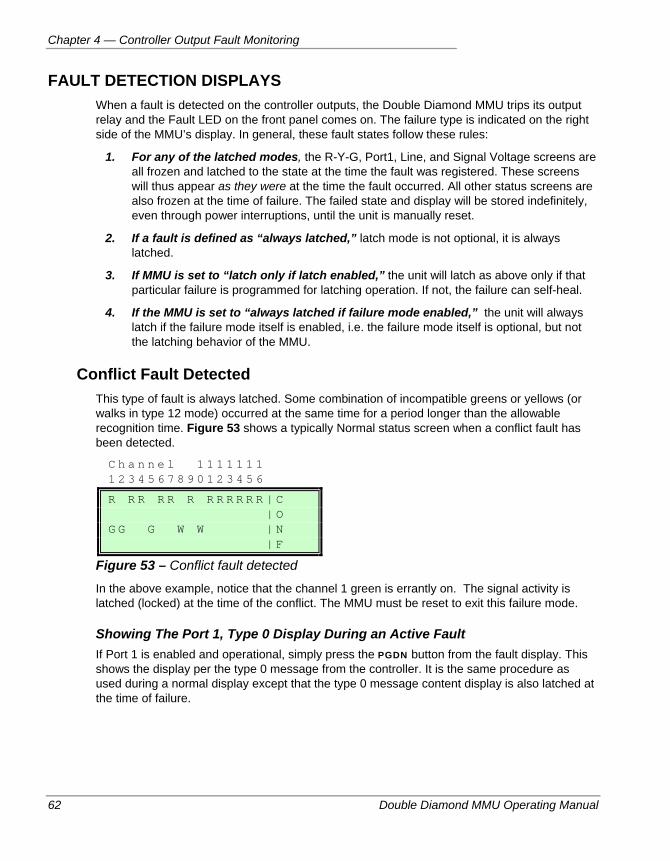
Chapter 4 — Controller Output Fault Monitoring
62 Double Diamond MMU Operating Manual
FAULT DETECTION DISPLAYS When a fault is detected on the controller outputs, the Double Diamond MMU trips its output relay and the Fault LED on the front panel comes on. The failure type is indicated on the right side of the MMU’s display. In general, these fault states follow these rules:
1. For any of the latched modes, the R-Y-G, Port1, Line, and Signal Voltage screens are all frozen and latched to the state at the time the fault was registered. These screens will thus appear as they were at the time the fault occurred. All other status screens are also frozen at the time of failure. The failed state and display will be stored indefinitely, even through power interruptions, until the unit is manually reset.
2. If a fault is defined as “always latched,” latch mode is not optional, it is always latched.
3. If MMU is set to “latch only if latch enabled,” the unit will latch as above only if that particular failure is programmed for latching operation. If not, the failure can self-heal.
4. If the MMU is set to “always latched if failure mode enabled,” the unit will always latch if the failure mode itself is enabled, i.e. the failure mode itself is optional, but not the latching behavior of the MMU.
Conflict Fault Detected This type of fault is always latched. Some combination of incompatible greens or yellows (or walks in type 12 mode) occurred at the same time for a period longer than the allowable recognition time. Figure 53 shows a typically Normal status screen when a conflict fault has been detected.
C h a n n e l 1 1 1 1 1 1 1 1 2 3 4 5 6 7 8 9 0 1 2 3 4 5 6
R R R R R R R R R R R R | C | O G G G W W | N | F
Figure 53 – Conflict fault detected
In the above example, notice that the channel 1 green is errantly on. The signal activity is latched (locked) at the time of the conflict. The MMU must be reset to exit this failure mode.
Showing The Port 1, Type 0 Display During an Active Fault If Port 1 is enabled and operational, simply press the PGDN button from the fault display. This shows the display per the type 0 message from the controller. It is the same procedure as used during a normal display except that the type 0 message content display is also latched at the time of failure.
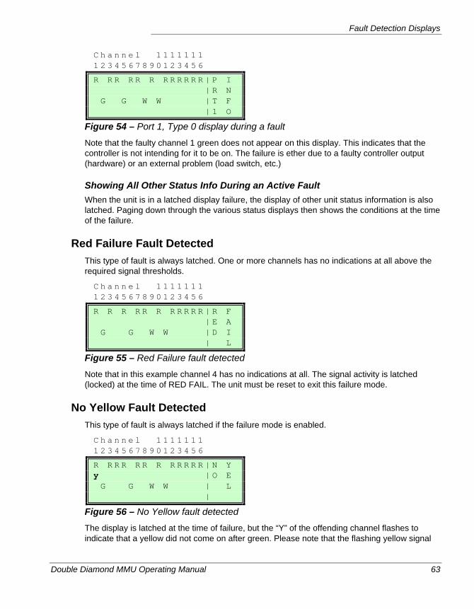
Fault Detection Displays
Double Diamond MMU Operating Manual 63
C h a n n e l 1 1 1 1 1 1 1 1 2 3 4 5 6 7 8 9 0 1 2 3 4 5 6
R R R R R R R R R R R R | P I | R N G G W W | T F | 1 O
Figure 54 – Port 1, Type 0 display during a fault
Note that the faulty channel 1 green does not appear on this display. This indicates that the controller is not intending for it to be on. The failure is ether due to a faulty controller output (hardware) or an external problem (load switch, etc.)
Showing All Other Status Info During an Active Fault When the unit is in a latched display failure, the display of other unit status information is also latched. Paging down through the various status displays then shows the conditions at the time of the failure.
Red Failure Fault Detected This type of fault is always latched. One or more channels has no indications at all above the required signal thresholds.
C h a n n e l 1 1 1 1 1 1 1 1 2 3 4 5 6 7 8 9 0 1 2 3 4 5 6
R R R R R R R R R R R | R F | E A G G W W | D I | L
Figure 55 – Red Failure fault detected
Note that in this example channel 4 has no indications at all. The signal activity is latched (locked) at the time of RED FAIL. The unit must be reset to exit this failure mode.
No Yellow Fault Detected This type of fault is always latched if the failure mode is enabled.
C h a n n e l 1 1 1 1 1 1 1 1 2 3 4 5 6 7 8 9 0 1 2 3 4 5 6
R R R R R R R R R R R R | N Y y | O E G G W W | L |
Figure 56 – No Yellow fault detected
The display is latched at the time of failure, but the “Y” of the offending channel flashes to indicate that a yellow did not come on after green. Please note that the flashing yellow signal
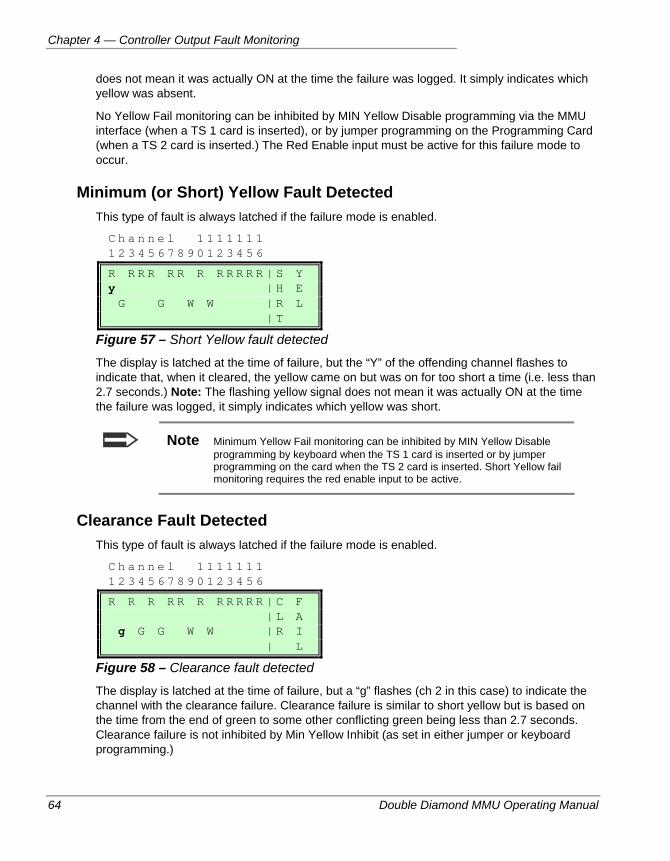
Chapter 4 — Controller Output Fault Monitoring
64 Double Diamond MMU Operating Manual
does not mean it was actually ON at the time the failure was logged. It simply indicates which yellow was absent.
No Yellow Fail monitoring can be inhibited by MIN Yellow Disable programming via the MMU interface (when a TS 1 card is inserted), or by jumper programming on the Programming Card (when a TS 2 card is inserted.) The Red Enable input must be active for this failure mode to occur.
Minimum (or Short) Yellow Fault Detected This type of fault is always latched if the failure mode is enabled.
C h a n n e l 1 1 1 1 1 1 1 1 2 3 4 5 6 7 8 9 0 1 2 3 4 5 6
R R R R R R R R R R R R | S Y y | H E G G W W | R L | T
Figure 57 – Short Yellow fault detected
The display is latched at the time of failure, but the “Y” of the offending channel flashes to indicate that, when it cleared, the yellow came on but was on for too short a time (i.e. less than 2.7 seconds.) Note: The flashing yellow signal does not mean it was actually ON at the time the failure was logged, it simply indicates which yellow was short.
Note Minimum Yellow Fail monitoring can be inhibited by MIN Yellow Disable programming by keyboard when the TS 1 card is inserted or by jumper programming on the card when the TS 2 card is inserted. Short Yellow fail monitoring requires the red enable input to be active.
Clearance Fault Detected This type of fault is always latched if the failure mode is enabled.
C h a n n e l 1 1 1 1 1 1 1 1 2 3 4 5 6 7 8 9 0 1 2 3 4 5 6
R R R R R R R R R R R | C F | L A g G G W W | R I | L
Figure 58 – Clearance fault detected
The display is latched at the time of failure, but a “g” flashes (ch 2 in this case) to indicate the channel with the clearance failure. Clearance failure is similar to short yellow but is based on the time from the end of green to some other conflicting green being less than 2.7 seconds. Clearance failure is not inhibited by Min Yellow Inhibit (as set in either jumper or keyboard programming.)
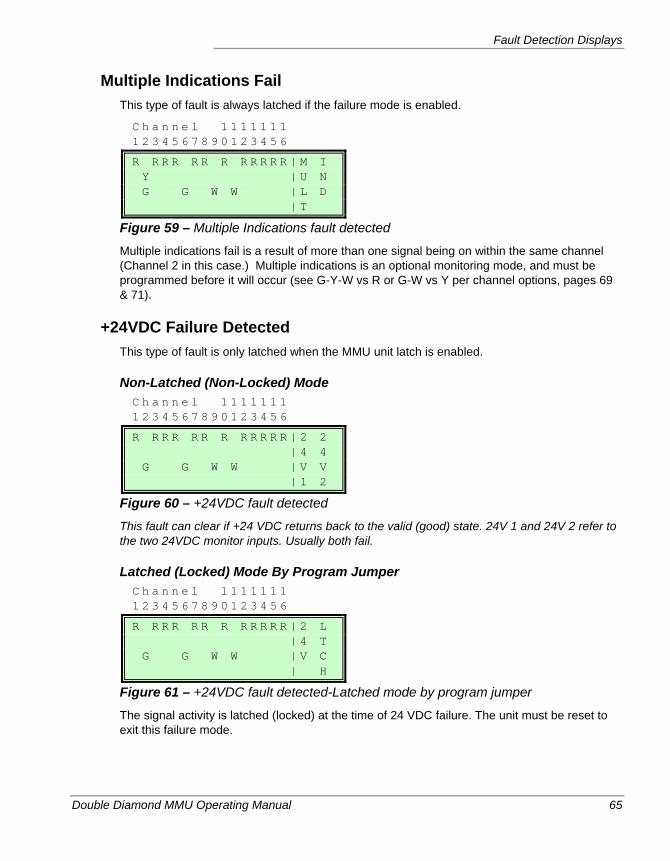
Fault Detection Displays
Double Diamond MMU Operating Manual 65
Multiple Indications Fail This type of fault is always latched if the failure mode is enabled.
C h a n n e l 1 1 1 1 1 1 1 1 2 3 4 5 6 7 8 9 0 1 2 3 4 5 6
R R R R R R R R R R R R | M I Y | U N G G W W | L D | T
Figure 59 – Multiple Indications fault detected
Multiple indications fail is a result of more than one signal being on within the same channel (Channel 2 in this case.) Multiple indications is an optional monitoring mode, and must be programmed before it will occur (see G-Y-W vs R or G-W vs Y per channel options, pages 69 & 71).
+24VDC Failure Detected This type of fault is only latched when the MMU unit latch is enabled.
Non-Latched (Non-Locked) Mode C h a n n e l 1 1 1 1 1 1 1 1 2 3 4 5 6 7 8 9 0 1 2 3 4 5 6
R R R R R R R R R R R R | 2 2 | 4 4 G G W W | V V | 1 2
Figure 60 – +24VDC fault detected
This fault can clear if +24 VDC returns back to the valid (good) state. 24V 1 and 24V 2 refer to the two 24VDC monitor inputs. Usually both fail.
Latched (Locked) Mode By Program Jumper C h a n n e l 1 1 1 1 1 1 1 1 2 3 4 5 6 7 8 9 0 1 2 3 4 5 6
R R R R R R R R R R R R | 2 L | 4 T G G W W | V C | H
Figure 61 – +24VDC fault detected-Latched mode by program jumper
The signal activity is latched (locked) at the time of 24 VDC failure. The unit must be reset to exit this failure mode.
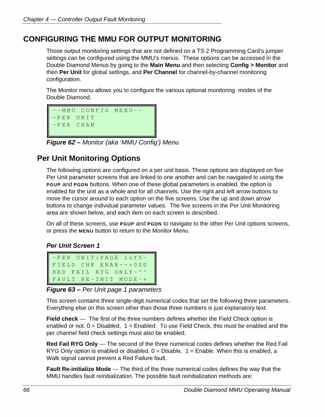
Chapter 4 — Controller Output Fault Monitoring
66 Double Diamond MMU Operating Manual
CONFIGURING THE MMU FOR OUTPUT MONITORING Those output monitoring settings that are not defined on a TS 2 Programming Card’s jumper settings can be configured using the MMU’s menus. These options can be accessed in the Double Diamond Menus by going to the Main Menu and then selecting Config > Monitor and then Per Unit for global settings, and Per Channel for channel-by-channel monitoring configuration.
The Monitor menu allows you to configure the various optional monitoring modes of the Double Diamond.
- - M M U C O N F I G M E N U - - - P E R U N I T - P E R C H A N
Figure 62 – Monitor (aka ‘MMU Config’) Menu
Per Unit Monitoring Options The following options are configured on a per unit basis. These options are displayed on five Per Unit parameter screens that are linked to one another and can be navigated to using the PGUP and PGDN buttons. When one of these global parameters is enabled, the option is enabled for the unit as a whole and for all channels. Use the right and left arrow buttons to move the cursor around to each option on the five screens. Use the up and down arrow buttons to change individual parameter values. The five screens in the Per Unit Monitoring area are shown below, and each item on each screen is described.
On all of these screens, use PGUP and PGDN to navigate to the other Per Unit options screens, or press the MENU button to return to the Monitor Menu.
Per Unit Screen 1
- P E R U N I T : P A G E 1 o f 5 - F I E L D C H K E N A B - - > 0 0 0 R E D F A I L R Y G O N L Y - ^ ^ F A U L T R E - I N I T M O D E - +
Figure 63 – Per Unit page 1 parameters
This screen contains three single-digit numerical codes that set the following three parameters. Everything else on this screen other than those three numbers is just explanatory text.
Field check — The first of the three numbers defines whether the Field Check option is enabled or not. 0 = Disabled, 1 = Enabled. To use Field Check, this must be enabled and the per channel field check settings must also be enabled.
Red Fail RYG Only — The second of the three numerical codes defines whether the Red Fail RYG Only option is enabled or disabled. 0 = Disable, 1 = Enable. When this is enabled, a Walk signal cannot prevent a Red Failure fault.
Fault Re-initialize Mode — The third of the three numerical codes defines the way that the MMU handles fault reinitialization. The possible fault reinitialization methods are:
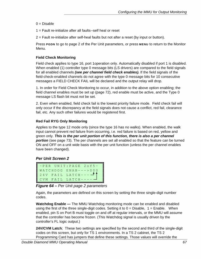
Configuring the MMU for Output Monitoring
Double Diamond MMU Operating Manual 67
0 = Disable
1 = Fault re-initialize after all faults--self heal or reset
2 = Fault re-initialize after self-heal faults but not after a reset (by input or button).
Press PGDN to go to page 2 of the Per Unit parameters, or press MENU to return to the Monitor Menu.
Field Check Monitoring Field check applies to type 16, port 1operation only. Automatically disabled if port 1 is disabled. When enabled (1) controller type 0 message bits (LS drivers) are compared to the field signals for all enabled channels (see per channel field check enables). If the field signals of the field-check-enabled channels do not agree with the type 0 message bits for 10 consecutive messages a FIELD CHECK FAIL will be declared and the output relay will drop.
1. In order for Field Check Monitoring to occur, in addition to the above option enabling; the field channel enables must be set up (page 72), red enable must be active, and the Type 0 message LS flash bit must not be set.
2. Even when enabled, field check fail is the lowest priority failure mode. Field check fail will only occur if the discrepancy at the field signals does not cause a conflict, red fail, clearance fail, etc. Any such other failures would be registered first.
Red Fail RYG Only Monitoring Applies to the type 12 mode only (since the type 16 has no walks). When enabled, the walk input cannot prevent red failure from occurring, i.e. red failure is based on red, yellow and green only. This is the per unit portion of this function, there is also a per channel portion (see page 73). The per channels are set all enabled so that the feature can be turned ON and OFF on a unit wide basis with the per unit function (unless the per channel enables have been changed).
Per Unit Screen 2
- P E R U N I T : P A G E 2 o f 5 - W A T C H D O G E N A B - - - > 0 0 0 2 4 V F A I L L A T C H - - - - C V M F A I L L A T C H - - - - -
Figure 64 – Per Unit page 2 parameters
Again, the parameters are defined on this screen by setting the three single-digit number codes.
Watchdog Enable — The MMU Watchdog monitoring mode can be enabled and disabled using the first of the three single-digit codes. Setting it to 0 = Disable, 1 = Enable. When enabled, pin S on Port B must toggle on and off at regular intervals, or the MMU will assume that the controller has become frozen. (This Watchdog signal is usually driven by the controller’s FL logic output.)
24V/CVM Latch; These two settings are specified by the second and third of the single-digit codes on this screen, but only for TS 1 environments. In a TS 2 cabinet, the TS 2 Programming Card has jumpers that define these settings. Those values will override the
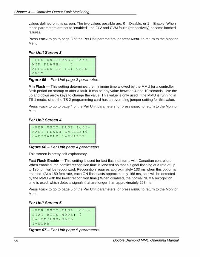
Chapter 4 — Controller Output Fault Monitoring
68 Double Diamond MMU Operating Manual
values defined on this screen. The two values possible are: 0 = Disable, or 1 = Enable. When these parameters are set to ‘enabled’, the 24V and CVM faults (respectively) become latched failures.
Press PGDN to go to page 3 of the Per Unit parameters, or press MENU to return to the Monitor Menu.
Per Unit Screen 3
- P E R U N I T : P A G E 3 o f 5 - M I N F L A S H : 7 A P P L I E S I F T S 1 C A R D O N L Y .
Figure 65 – Per Unit page 3 parameters
Min Flash — This setting determines the minimum time allowed by the MMU for a controller flash period on startup or after a fault. It can be any value between 4 and 10 seconds. Use the up and down arrow keys to change the value. This value is only used if the MMU is running in TS 1 mode, since the TS 2 programming card has an overriding jumper setting for this value.
Press PGDN to go to page 4 of the Per Unit parameters, or press MENU to return to the Monitor Menu.
Per Unit Screen 4
- P E R U N I T : P A G E 4 o f 5 - F A S T F L A S H E N A B L E : 0 0 = D I S A B L E 1 = E N A B L E
Figure 66 – Per Unit page 4 parameters
This screen is pretty self-explanatory.
Fast Flash Enable — This setting is used for fast flash left turns with Canadian controllers. When enabled, the conflict recognition time is lowered so that a signal flashing at a rate of up to 180 fpm will be recognized. Recognition requires approximately 133 ms when this option is enabled. (At a 180 fpm rate, each ON flash lasts approximately 166 ms, so it will be detected by the MMU with the lower recognition time.) When disabled, the normal NEMA recognition time is used, which detects signals that are longer than approximately 267 ms.
Press PGDN to go to page 5 of the Per Unit parameters, or press MENU to return to the Monitor Menu.
Per Unit Screen 5
- P E R U N I T : P A G E 5 o f 5 - S T A T B I T S M O D E : 0 0 = L S M / L N M / E L R B 1 = E L R A
Figure 67 – Per Unit page 5 parameters
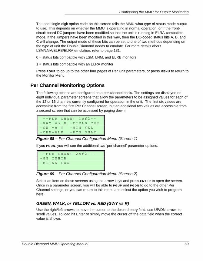
Configuring the MMU for Output Monitoring
Double Diamond MMU Operating Manual 69
The one single-digit option code on this screen tells the MMU what type of status mode output to use. This depends on whether the MMU is operating in normal operation, or if the front-circuit board DC jumpers have been modified so that the unit is running in ELRA-compatible mode. If the jumpers have been modified in this way, then the DC-coded status bits A, B, and C will change. The output mode of these bits can be set to one of two methods depending on the type of unit the Double Diamond needs to emulate. For more details about LSM/LNM/ELRB/ELRA emulation, refer to page 131.
0 = status bits compatible with LSM, LNM, and ELRB monitors
1 = status bits compatible with an ELRA monitor
Press PGUP to go up to the other four pages of Per Unit parameters, or press MENU to return to the Monitor Menu.
Per Channel Monitoring Options The following options are configured on a per channel basis. The settings are displayed on eight individual parameter screens that allow the parameters to be assigned values for each of the 12 or 16 channels currently configured for operation in the unit. The first six values are accessible from the first Per Channel screen, but an additional two values are accessible from a second screen that can be accessed by paging down.
- - P E R C H A N : 1 o f 2 - - - G W Y v s R - F I E L D C H K - G W v s Y - M I N Y E L - C H N = W L K - R Y G O N L Y
Figure 68 – Per Channel Configuration Menu (Screen 1)
If you PGDN, you will see the additional two ‘per channel’ parameter options.
- - P E R C H A N : 2 o f 2 - - - G G I N H I B - B L I N K L O G
Figure 69 – Per Channel Configuration Menu (Screen 2)
Select an item on these screens using the arrow keys and press ENTER to open the screen. Once in a parameter screen, you will be able to PGUP and PGDN to go to the other Per Channel settings, or you can return to this menu and select the option you wish to program here.
GREEN, WALK, or YELLOW vs. RED (GWY vs R) Use the right/left arrows to move the cursor to the desired entry field, use UP/DN arrows to scroll values. To load hit Enter or simply move the cursor off the data field when the correct value is shown.
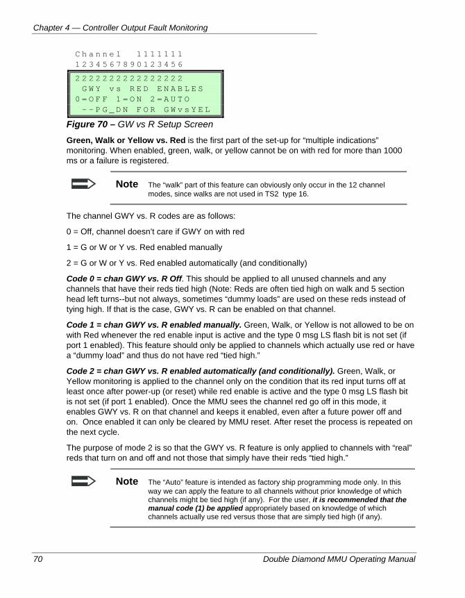
Chapter 4 — Controller Output Fault Monitoring
70 Double Diamond MMU Operating Manual
C h a n n e l 1 1 1 1 1 1 1 1 2 3 4 5 6 7 8 9 0 1 2 3 4 5 6
2 2 2 2 2 2 2 2 2 2 2 2 2 2 2 2 G W Y v s R E D E N A B L E S 0 = O F F 1 = O N 2 = A U T O - - P G _ D N F O R G W v s Y E L
Figure 70 – GW vs R Setup Screen
Green, Walk or Yellow vs. Red is the first part of the set-up for “multiple indications” monitoring. When enabled, green, walk, or yellow cannot be on with red for more than 1000 ms or a failure is registered.
Note The “walk” part of this feature can obviously only occur in the 12 channel modes, since walks are not used in TS2 type 16.
The channel GWY vs. R codes are as follows:
0 = Off, channel doesn’t care if GWY on with red
1 = G or W or Y vs. Red enabled manually
2 = G or W or Y vs. Red enabled automatically (and conditionally)
Code 0 = chan GWY vs. R Off. This should be applied to all unused channels and any channels that have their reds tied high (Note: Reds are often tied high on walk and 5 section head left turns--but not always, sometimes “dummy loads” are used on these reds instead of tying high. If that is the case, GWY vs. R can be enabled on that channel.
Code 1 = chan GWY vs. R enabled manually. Green, Walk, or Yellow is not allowed to be on with Red whenever the red enable input is active and the type 0 msg LS flash bit is not set (if port 1 enabled). This feature should only be applied to channels which actually use red or have a “dummy load” and thus do not have red “tied high.”
Code 2 = chan GWY vs. R enabled automatically (and conditionally). Green, Walk, or Yellow monitoring is applied to the channel only on the condition that its red input turns off at least once after power-up (or reset) while red enable is active and the type 0 msg LS flash bit is not set (if port 1 enabled). Once the MMU sees the channel red go off in this mode, it enables GWY vs. R on that channel and keeps it enabled, even after a future power off and on. Once enabled it can only be cleared by MMU reset. After reset the process is repeated on the next cycle.
The purpose of mode 2 is so that the GWY vs. R feature is only applied to channels with “real” reds that turn on and off and not those that simply have their reds “tied high.”
Note The “Auto” feature is intended as factory ship programming mode only. In this way we can apply the feature to all channels without prior knowledge of which channels might be tied high (if any). For the user, it is recommended that the manual code (1) be applied appropriately based on knowledge of which channels actually use red versus those that are simply tied high (if any).
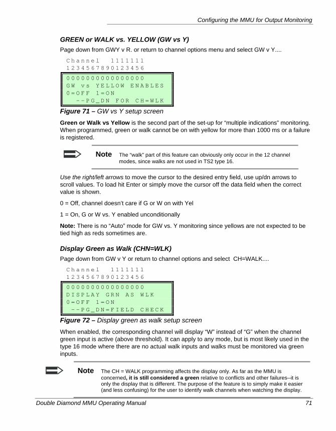
Configuring the MMU for Output Monitoring
Double Diamond MMU Operating Manual 71
GREEN or WALK vs. YELLOW (GW vs Y) Page down from GWY v R. or return to channel options menu and select GW v Y....
C h a n n e l 1 1 1 1 1 1 1 1 2 3 4 5 6 7 8 9 0 1 2 3 4 5 6
0 0 0 0 0 0 0 0 0 0 0 0 0 0 0 0 G W v s Y E L L O W E N A B L E S 0 = O F F 1 = O N - - P G _ D N F O R C H = W L K
Figure 71 – GW vs Y setup screen
Green or Walk vs Yellow is the second part of the set-up for “multiple indications” monitoring. When programmed, green or walk cannot be on with yellow for more than 1000 ms or a failure is registered.
Note The “walk” part of this feature can obviously only occur in the 12 channel modes, since walks are not used in TS2 type 16.
Use the right/left arrows to move the cursor to the desired entry field, use up/dn arrows to scroll values. To load hit Enter or simply move the cursor off the data field when the correct value is shown.
0 = Off, channel doesn’t care if G or W on with Yel
1 = On, G or W vs. Y enabled unconditionally
Note: There is no “Auto” mode for GW vs. Y monitoring since yellows are not expected to be tied high as reds sometimes are.
Display Green as Walk (CHN=WLK) Page down from GW v Y or return to channel options and select CH=WALK....
C h a n n e l 1 1 1 1 1 1 1 1 2 3 4 5 6 7 8 9 0 1 2 3 4 5 6
0 0 0 0 0 0 0 0 0 0 0 0 0 0 0 0 D I S P L A Y G R N A S W L K 0 = O F F 1 = O N - - P G _ D N = F I E L D C H E C K
Figure 72 – Display green as walk setup screen
When enabled, the corresponding channel will display “W” instead of “G” when the channel green input is active (above threshold). It can apply to any mode, but is most likely used in the type 16 mode where there are no actual walk inputs and walks must be monitored via green inputs.
Note The CH = WALK programming affects the display only. As far as the MMU is concerned, it is still considered a green relative to conflicts and other failures--it is only the display that is different. The purpose of the feature is to simply make it easier (and less confusing) for the user to identify walk channels when watching the display.
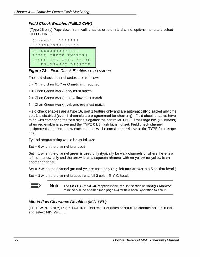
Chapter 4 — Controller Output Fault Monitoring
72 Double Diamond MMU Operating Manual
Field Check Enables (FIELD CHK) (Type 16 only) Page down from walk enables or return to channel options menu and select FIELD CHK.....
C h a n n e l 1 1 1 1 1 1 1 1 2 3 4 5 6 7 8 9 0 1 2 3 4 5 6
0 0 0 0 0 0 0 0 0 0 0 0 0 0 0 0 F I E L D C H E C K E N A B L E S 0 = O F F 1 = G 2 = Y G 3 = R Y G - - P G _ D N = M Y C D I S A B L E
Figure 73 – Field Check Enables setup screen
The field check channel codes are as follows:
0 = Off, no chan R, Y or G matching required
1 = Chan Green (walk) only must match
2 = Chan Green (walk) and yellow must match
3 = Chan Green (walk), yel, and red must match
Field check enables are a type 16, port 1 feature only and are automatically disabled any time port 1 is disabled (even if channels are programmed for checking). Field check enables have to do with comparing the field signals against the controller TYPE 0 message bits (LS drivers) when red enable is active and the TYPE 0 LS flash bit is not set. Field check channel assignments determine how each channel will be considered relative to the TYPE 0 message bits.
Typical programming would be as follows:
Set = 0 when the channel is unused
Set = 1 when the channel green is used only (typically for walk channels or where there is a left turn arrow only and the arrow is on a separate channel with no yellow (or yellow is on another channel).
Set = 2 when the channel grn and yel are used only (e.g. left turn arrows in a 5 section head.)
Set = 3 when the channel is used for a full 3 color, R-Y-G head.
Note The FIELD CHECK MON option in the Per Unit section of Config > Monitor must be also be enabled (see page 66) for field check operation to occur.
Min Yellow Clearance Disables (MIN YEL) (TS 1 CARD ONLY) Page down from field check enables or return to channel options menu and select MIN YEL.....
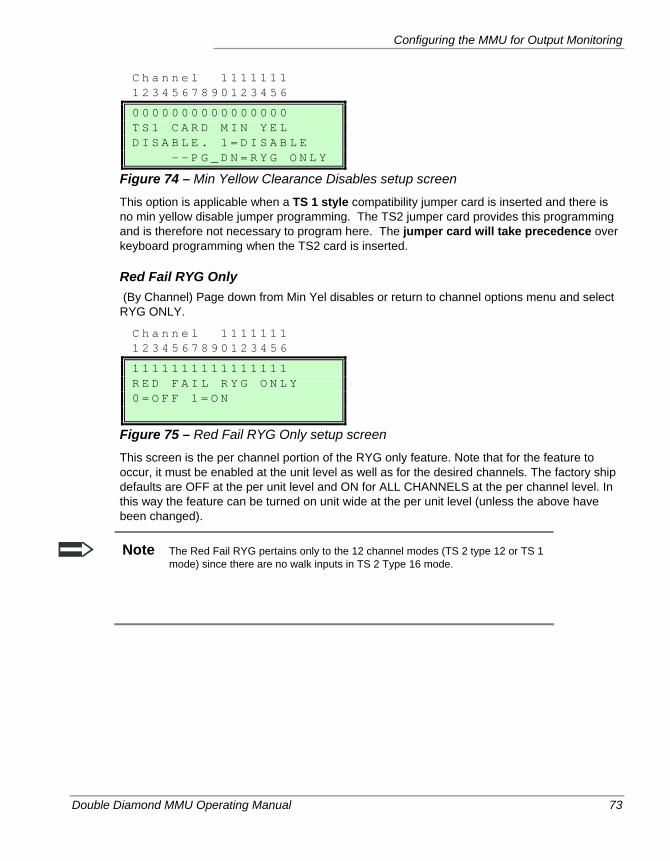
Configuring the MMU for Output Monitoring
Double Diamond MMU Operating Manual 73
C h a n n e l 1 1 1 1 1 1 1 1 2 3 4 5 6 7 8 9 0 1 2 3 4 5 6
0 0 0 0 0 0 0 0 0 0 0 0 0 0 0 0 T S 1 C A R D M I N Y E L D I S A B L E . 1 = D I S A B L E - - P G _ D N = R Y G O N L Y
Figure 74 – Min Yellow Clearance Disables setup screen
This option is applicable when a TS 1 style compatibility jumper card is inserted and there is no min yellow disable jumper programming. The TS2 jumper card provides this programming and is therefore not necessary to program here. The jumper card will take precedence over keyboard programming when the TS2 card is inserted.
Red Fail RYG Only (By Channel) Page down from Min Yel disables or return to channel options menu and select RYG ONLY.
C h a n n e l 1 1 1 1 1 1 1 1 2 3 4 5 6 7 8 9 0 1 2 3 4 5 6
1 1 1 1 1 1 1 1 1 1 1 1 1 1 1 1 R E D F A I L R Y G O N L Y 0 = O F F 1 = O N
Figure 75 – Red Fail RYG Only setup screen
This screen is the per channel portion of the RYG only feature. Note that for the feature to occur, it must be enabled at the unit level as well as for the desired channels. The factory ship defaults are OFF at the per unit level and ON for ALL CHANNELS at the per channel level. In this way the feature can be turned on unit wide at the per unit level (unless the above have been changed).
Note The Red Fail RYG pertains only to the 12 channel modes (TS 2 type 12 or TS 1 mode) since there are no walk inputs in TS 2 Type 16 mode.
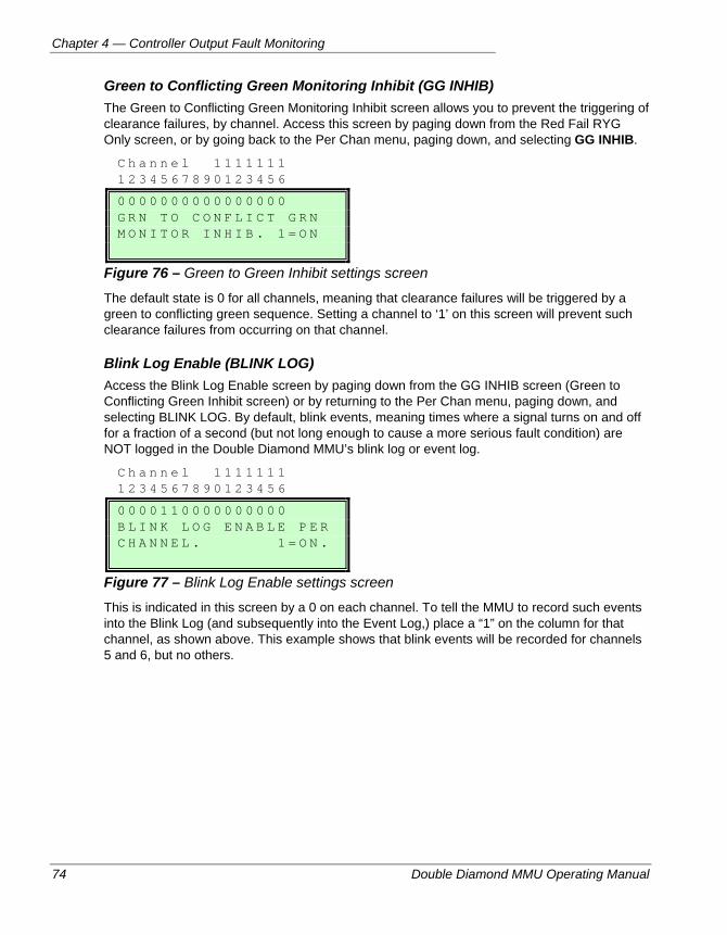
Chapter 4 — Controller Output Fault Monitoring
74 Double Diamond MMU Operating Manual
Green to Conflicting Green Monitoring Inhibit (GG INHIB) The Green to Conflicting Green Monitoring Inhibit screen allows you to prevent the triggering of clearance failures, by channel. Access this screen by paging down from the Red Fail RYG Only screen, or by going back to the Per Chan menu, paging down, and selecting GG INHIB.
C h a n n e l 1 1 1 1 1 1 1 1 2 3 4 5 6 7 8 9 0 1 2 3 4 5 6
0 0 0 0 0 0 0 0 0 0 0 0 0 0 0 0 G R N T O C O N F L I C T G R N M O N I T O R I N H I B . 1 = O N
Figure 76 – Green to Green Inhibit settings screen
The default state is 0 for all channels, meaning that clearance failures will be triggered by a green to conflicting green sequence. Setting a channel to ‘1’ on this screen will prevent such clearance failures from occurring on that channel.
Blink Log Enable (BLINK LOG) Access the Blink Log Enable screen by paging down from the GG INHIB screen (Green to Conflicting Green Inhibit screen) or by returning to the Per Chan menu, paging down, and selecting BLINK LOG. By default, blink events, meaning times where a signal turns on and off for a fraction of a second (but not long enough to cause a more serious fault condition) are NOT logged in the Double Diamond MMU’s blink log or event log.
C h a n n e l 1 1 1 1 1 1 1 1 2 3 4 5 6 7 8 9 0 1 2 3 4 5 6
0 0 0 0 1 1 0 0 0 0 0 0 0 0 0 0 B L I N K L O G E N A B L E P E R C H A N N E L . 1 = O N .
Figure 77 – Blink Log Enable settings screen
This is indicated in this screen by a 0 on each channel. To tell the MMU to record such events into the Blink Log (and subsequently into the Event Log,) place a “1” on the column for that channel, as shown above. This example shows that blink events will be recorded for channels 5 and 6, but no others.
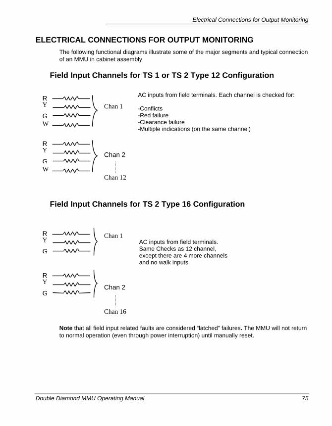
Electrical Connections for Output Monitoring
Double Diamond MMU Operating Manual 75
ELECTRICAL CONNECTIONS FOR OUTPUT MONITORING The following functional diagrams illustrate some of the major segments and typical connection of an MMU in cabinet assembly
Field Input Channels for TS 1 or TS 2 Type 12 Configuration
Field Input Channels for TS 2 Type 16 Configuration
Note that all field input related faults are considered “latched” failures. The MMU will not return to normal operation (even through power interruption) until manually reset.
Chan 1 R Y
GW
AC inputs from field terminals. Each channel is checked for: -Conflicts -Red failure -Clearance failure -Multiple indications (on the same channel)
Chan 2
Chan 12
AC inputs from field terminals. Same Checks as 12 channel, except there are 4 more channels and no walk inputs.
R Y
GW
Chan 1
Chan 2
Chan 16
R Y
G
R Y
G
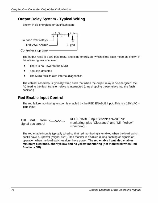
Chapter 4 — Controller Output Fault Monitoring
76 Double Diamond MMU Operating Manual
Output Relay System - Typical Wiring Shown in de-energized or fault/flash state
The output relay is a two pole relay, and is de-energized (which is the flash mode, as shown in the above figure) whenever:
There is no Power to the MMU
A fault is detected
The MMU fails its own internal diagnostics
The cabinet assembly is typically wired such that when the output relay is de-energized: the AC feed to the flash transfer relays is interrupted (thus dropping those relays into the flash position.)
Red Enable Input Control The red failure monitoring function is enabled by the RED ENABLE input. This is a 120 VAC = True input
The red enable input is typically wired so that red monitoring is enabled when the load switch packs have AC power (“signal bus”). Red monitor is disabled during flashing or signals off operation when the load switches don’t have power. The red enable input also enables minimum clearance, short yellow and no yellow monitoring (not monitored when Red Enable is Off)
To flash xfer relays 120 VAC source
Controller stop time
L. gnd
120 VAC from signal bus control
RED ENABLE input; enables “Red Fail” monitoring, plus ”Clearance” and “Min Yellow” monitoring.
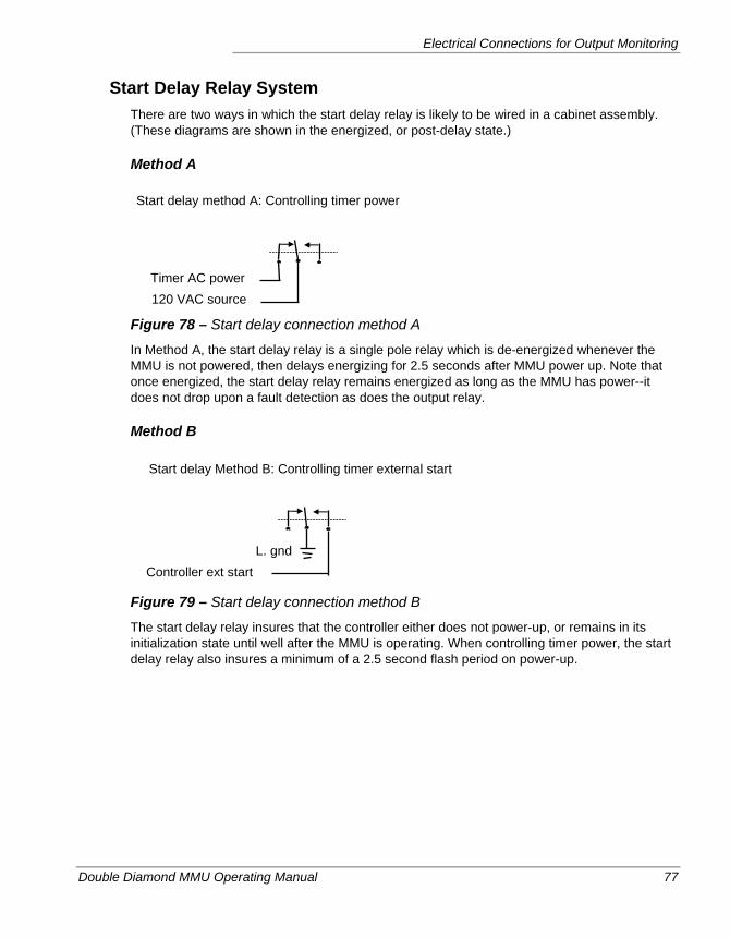
Electrical Connections for Output Monitoring
Double Diamond MMU Operating Manual 77
Start Delay Relay System There are two ways in which the start delay relay is likely to be wired in a cabinet assembly. (These diagrams are shown in the energized, or post-delay state.)
Method A
Figure 78 – Start delay connection method A
In Method A, the start delay relay is a single pole relay which is de-energized whenever the MMU is not powered, then delays energizing for 2.5 seconds after MMU power up. Note that once energized, the start delay relay remains energized as long as the MMU has power--it does not drop upon a fault detection as does the output relay.
Method B
Figure 79 – Start delay connection method B
The start delay relay insures that the controller either does not power-up, or remains in its initialization state until well after the MMU is operating. When controlling timer power, the start delay relay also insures a minimum of a 2.5 second flash period on power-up.
Timer AC power 120 VAC source
Start delay method A: Controlling timer power
Start delay Method B: Controlling timer external start
L. gnd Controller ext start
Chapter 4 — Controller Output Fault Monitoring
78 Double Diamond MMU Operating Manual
Effect of the “Type 0” Message LS Flash Command When the MMU is in type 16 mode and the controller is operating in “type 1” mode (BIU’s instead of MSA, B, and C), the controller issues commands to the MMU and BIU’s. The type 0 message from the controller contains all the load switch driver bits. Bit 112 of this message is the “LS flash” command. This bit being active is much like red enabled not being active in terms of MMU monitoring. As a result, when this LS flash bit is active; red fail, yellow monitoring, and minimum clearance are all disabled.
Compatibility Checking By The Controller Since the MMU presents its Programming Card information to the controller via port 1, and the controller knows how its phasing has been assigned to MMU channels, the controller can check the programming card to see if the jumpers are valid. Some manufacturers have this capability and it is useful. You should, however, always check your own work and use the controller only as verification.
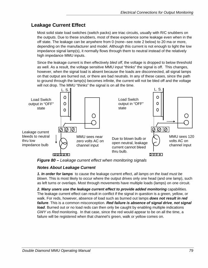
Electrical Connections for Output Monitoring
Double Diamond MMU Operating Manual 79
Leakage Current Effect Most solid state load switches (switch packs) are triac circuits, usually with R/C snubbers on the outputs. Due to these snubbers, most of these experience some leakage even when in the off state. The leakage can be anywhere from 0 (none--see note 2 below) to 20 ma or more, depending on the manufacturer and model. Although this current is not enough to light the low impedance signal lamp(s), it normally flows through them to neutral instead of the relatively high impedance MMU inputs.
Since the leakage current is then effectively bled off, the voltage is dropped to below threshold as well. As a result, the voltage sensitive MMU input “thinks” the signal is off. This changes, however, when the signal load is absent because the loads are disconnected, all signal lamps on that output are burned out, or there are bad neutrals. In any of these cases, since the path to ground through the lamp(s) becomes infinite, the current will not be bled off and the voltage will not drop. The MMU “thinks” the signal is on all the time.
Figure 80 – Leakage current effect when monitoring signals
Notes About Leakage Current 1. In order for lamps to cause the leakage current effect, all lamps on the load must be blown. This is most likely to occur where the output drives only one head (and one lamp), such as left turns or overlaps. Most through movements have multiple loads (lamps) on one circuit. 2. Many users use the leakage current effect to provide added monitoring capabilities. The leakage current effect can result in conflict if the signal in question is a green, yellow, or walk. For reds, however, absence of load such as burned out lamps does not result in red failure. This is a common misconception. Red failure is absence of signal drive, not signal load. Burned out or no load reds can then only be caught by enabling multiple indications GWY vs Red monitoring. In that case, since the red would appear to be on all the time, a failure will be registered when that channel’s green, walk or yellow comes on.
Leakage current bleeds to neutral thru low impedance bulb
Load Switch output in “OFF”
state
MMU sees near zero volts AC on channel input
Due to blown bulb or open neutral, leakage current cannot bleed thru bulb.
Load Switch output in “OFF” state
MMU sees 120 volts AC on channel input
L. S. L. S.
Chapter 4 — Controller Output Fault Monitoring
80 Double Diamond MMU Operating Manual
Double Diamond MMU Operating Manual 81
Chapter 5 — CVM: Cabinet Voltage Monitoring
This chapter describes the voltage monitoring capabilities of the Double Diamond. The following topics are discussed in detail in this chapter:
• The available types of voltage monitoring, on page 82.
• A description of CVM:Cabinet voltage monitoring, on page 83.
• Additional details about voltage monitoring, on page 86.
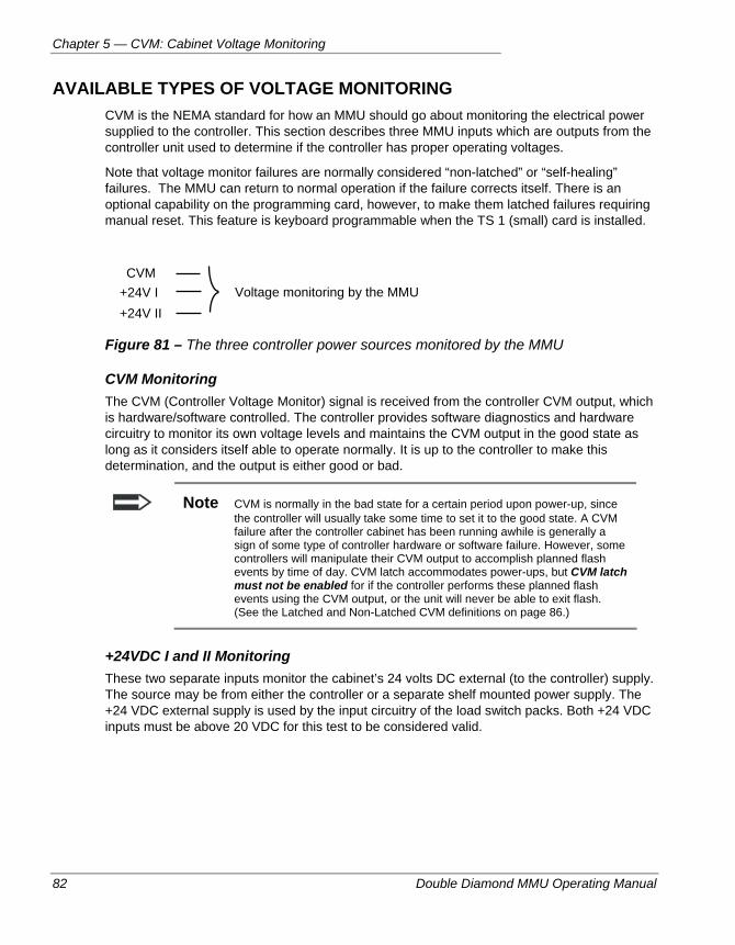
Chapter 5 — CVM: Cabinet Voltage Monitoring
82 Double Diamond MMU Operating Manual
AVAILABLE TYPES OF VOLTAGE MONITORING CVM is the NEMA standard for how an MMU should go about monitoring the electrical power supplied to the controller. This section describes three MMU inputs which are outputs from the controller unit used to determine if the controller has proper operating voltages.
Note that voltage monitor failures are normally considered “non-latched” or “self-healing” failures. The MMU can return to normal operation if the failure corrects itself. There is an optional capability on the programming card, however, to make them latched failures requiring manual reset. This feature is keyboard programmable when the TS 1 (small) card is installed.
Figure 81 – The three controller power sources monitored by the MMU
CVM Monitoring The CVM (Controller Voltage Monitor) signal is received from the controller CVM output, which is hardware/software controlled. The controller provides software diagnostics and hardware circuitry to monitor its own voltage levels and maintains the CVM output in the good state as long as it considers itself able to operate normally. It is up to the controller to make this determination, and the output is either good or bad.
Note CVM is normally in the bad state for a certain period upon power-up, since the controller will usually take some time to set it to the good state. A CVM failure after the controller cabinet has been running awhile is generally a sign of some type of controller hardware or software failure. However, some controllers will manipulate their CVM output to accomplish planned flash events by time of day. CVM latch accommodates power-ups, but CVM latch must not be enabled for if the controller performs these planned flash events using the CVM output, or the unit will never be able to exit flash. (See the Latched and Non-Latched CVM definitions on page 86.)
+24VDC I and II Monitoring These two separate inputs monitor the cabinet’s 24 volts DC external (to the controller) supply. The source may be from either the controller or a separate shelf mounted power supply. The +24 VDC external supply is used by the input circuitry of the load switch packs. Both +24 VDC inputs must be above 20 VDC for this test to be considered valid.
CVM +24V I +24V II
Voltage monitoring by the MMU
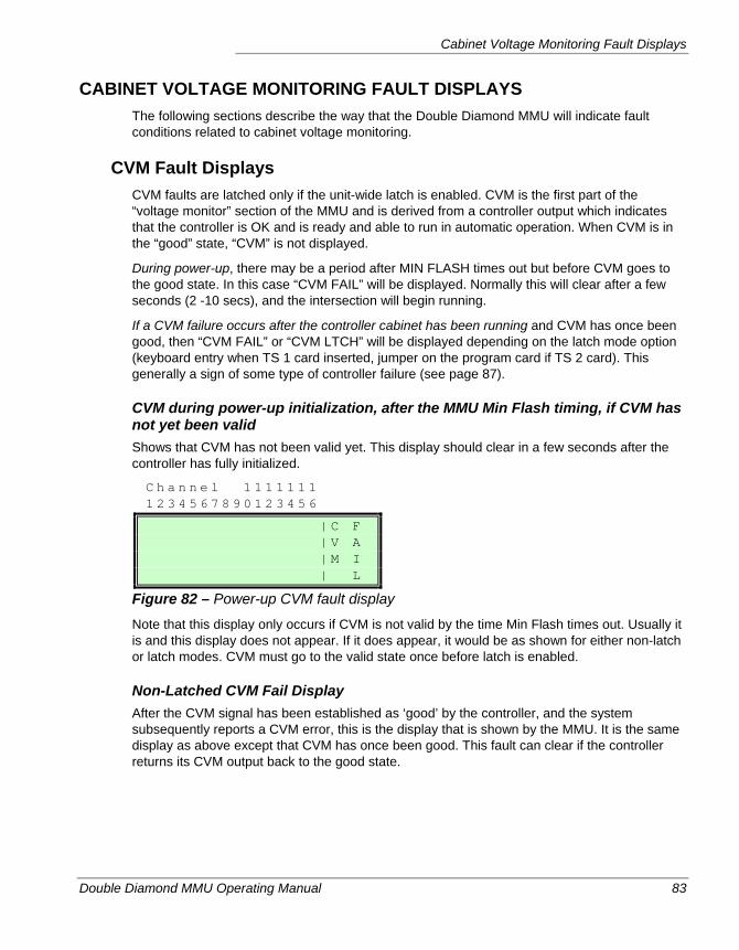
Cabinet Voltage Monitoring Fault Displays
Double Diamond MMU Operating Manual 83
CABINET VOLTAGE MONITORING FAULT DISPLAYS The following sections describe the way that the Double Diamond MMU will indicate fault conditions related to cabinet voltage monitoring.
CVM Fault Displays CVM faults are latched only if the unit-wide latch is enabled. CVM is the first part of the “voltage monitor” section of the MMU and is derived from a controller output which indicates that the controller is OK and is ready and able to run in automatic operation. When CVM is in the “good” state, “CVM” is not displayed.
During power-up, there may be a period after MIN FLASH times out but before CVM goes to the good state. In this case “CVM FAIL” will be displayed. Normally this will clear after a few seconds (2 -10 secs), and the intersection will begin running.
If a CVM failure occurs after the controller cabinet has been running and CVM has once been good, then “CVM FAIL” or “CVM LTCH” will be displayed depending on the latch mode option (keyboard entry when TS 1 card inserted, jumper on the program card if TS 2 card). This generally a sign of some type of controller failure (see page 87).
CVM during power-up initialization, after the MMU Min Flash timing, if CVM has not yet been valid Shows that CVM has not been valid yet. This display should clear in a few seconds after the controller has fully initialized.
C h a n n e l 1 1 1 1 1 1 1 1 2 3 4 5 6 7 8 9 0 1 2 3 4 5 6
| C F | V A | M I | L
Figure 82 – Power-up CVM fault display
Note that this display only occurs if CVM is not valid by the time Min Flash times out. Usually it is and this display does not appear. If it does appear, it would be as shown for either non-latch or latch modes. CVM must go to the valid state once before latch is enabled.
Non-Latched CVM Fail Display After the CVM signal has been established as ‘good’ by the controller, and the system subsequently reports a CVM error, this is the display that is shown by the MMU. It is the same display as above except that CVM has once been good. This fault can clear if the controller returns its CVM output back to the good state.
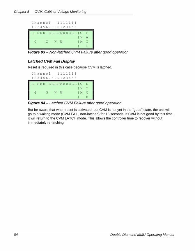
Chapter 5 — CVM: Cabinet Voltage Monitoring
84 Double Diamond MMU Operating Manual
C h a n n e l 1 1 1 1 1 1 1 1 2 3 4 5 6 7 8 9 0 1 2 3 4 5 6
R R R R R R R R R R R R R R | C F | V A G G W W | M I | L
Figure 83 – Non-latched CVM Failure after good operation
Latched CVM Fail Display Reset is required in this case because CVM is latched.
C h a n n e l 1 1 1 1 1 1 1 1 2 3 4 5 6 7 8 9 0 1 2 3 4 5 6
R R R R R R R R R R R R R R | C L | V T G G W W | M C | H
Figure 84 – Latched CVM Failure after good operation
But be aware that when reset is activated, but CVM is not yet in the “good” state, the unit will go to a waiting mode (CVM FAIL, non-latched) for 15 seconds. If CVM is not good by this time, it will return to the CVM LATCH mode. This allows the controller time to recover without immediately re-latching.
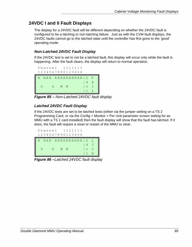
Cabinet Voltage Monitoring Fault Displays
Double Diamond MMU Operating Manual 85
24VDC I and II Fault Displays The display for a 24VDC fault will be different depending on whether the 24VDC fault is configured to be a latching or non-latching failure. Just as with the CVM fault displays, the 24VDC faults cannot go to the latched state until the controller has first gone to the ‘good’ operating mode.
Non-Latched 24VDC Fault Display If the 24VDC test is set to not be a latched fault, this display will occur only while the fault is happening. After the fault clears, the display will return to normal operation.
C h a n n e l 1 1 1 1 1 1 1 1 2 3 4 5 6 7 8 9 0 1 2 3 4 5 6
R R R R R R R R R R R R R R | 2 F | 4 A G G W W | v I | 1 L
Figure 85 – Non-Latched 24VDC fault display
Latched 24VDC Fault Display If the 24VDC tests are set to be latched tests (either via the jumper setting on a TS 2 Programming Card, or via the Config > Monitor > Per Unit parameter screen setting for an MMU with a TS 1 card installed) then the fault display will show that the fault has latched. If it does, the fault will require a reset or restart of the MMU to clear.
C h a n n e l 1 1 1 1 1 1 1 1 2 3 4 5 6 7 8 9 0 1 2 3 4 5 6
R R R R R R R R R R R R R R | 2 L | 4 T G G W W | v C | 1 H
Figure 86 –Latched 24VDC fault display
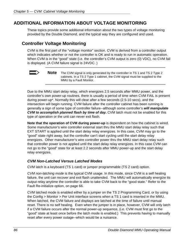
Chapter 5 — CVM: Cabinet Voltage Monitoring
86 Double Diamond MMU Operating Manual
ADDITIONAL INFORMATION ABOUT VOLTAGE MONITORING These topics provide some additional information about the two types of voltage monitoring provided by the Double Diamond, and the typical way they are configured and used.
Controller Voltage Monitoring CVM is the first part of the “voltage monitor” section. CVM is derived from a controller output which indicates whether or not the controller is OK and is ready to run in automatic operation. When CVM is in the “good” state (i.e. the controller’s CVM output is zero (0) VDC), no CVM fail is displayed. (A CVM failure signal is 24VDC. )
Note The CVM signal is only generated by the controller in TS 1 and TS 2 Type 2 cabinets. In a TS 2 Type 1 cabinet, the CVM signal must be supplied to the MMU by a Fault Monitor.
Due to the MMU start delay relay, which energizes 2.5 seconds after MMU power, and the controller’s own power-up routines, there is usually a period of time when CVM FAIL is present during power-up*. Normally this will clear after a few seconds (2.5-10 secs), and the intersection will begin running. CVM failure after the controller cabinet has been running is generally a sign of some type of controller failure--although some controller’s will manipulate CVM to accomplish planned flash by time of day. CVM latch must not be enabled for this type of operation or the unit can never exit flash.
Note that the operation of CVM during power-up is dependent on how the cabinet is wired. Some manufacturer’s wire controller external start thru the MMU start delay relay such that EXT START is applied until the start delay relay energizes. In this case, CVM may go to the “good” state right away, but the controller can’t start cycling until the start delay relay energizes. Other manufacturer’s wire controller power thru the MMU start delay relay such that controller power is not applied until the start delay relay energizes. In this case CVM can not go to the “good” state for at least 2.2 seconds after MMU power-up and the start delay relay energizes.
CVM Non-Latched Versus Latched Modes CVM latch is a keyboard (TS 1 card) or jumper programmable (TS 2 card) option.
CVM non-latching mode is the typical CVM usage. In this mode, since CVM is a self healing failure, the unit can recover and exit flash unattended. The MMU will automatically energize its output relay anytime the controller is able to take CVM back to the “good state.” Refer to the Fault Re-initialize option, on page 66.
CVM latched mode is enabled either by a jumper on the TS 2 Programming Card, or by using the Config > Monitor > Per Unit interface screens when a TS 1 card is inserted in the MMU. When latched, the CVM failure and displays are latched at the time of failure until manual reset. There is no self healing. Even when the jumper is in place, however, CVM will only latch if a CVM failure occurs after the normal power-up sequence, (i.e. CVM must first go to the “good” state at least once before the latch mode is enabled.) This prevents having to manually reset after every power outage--which would be a nuisance.
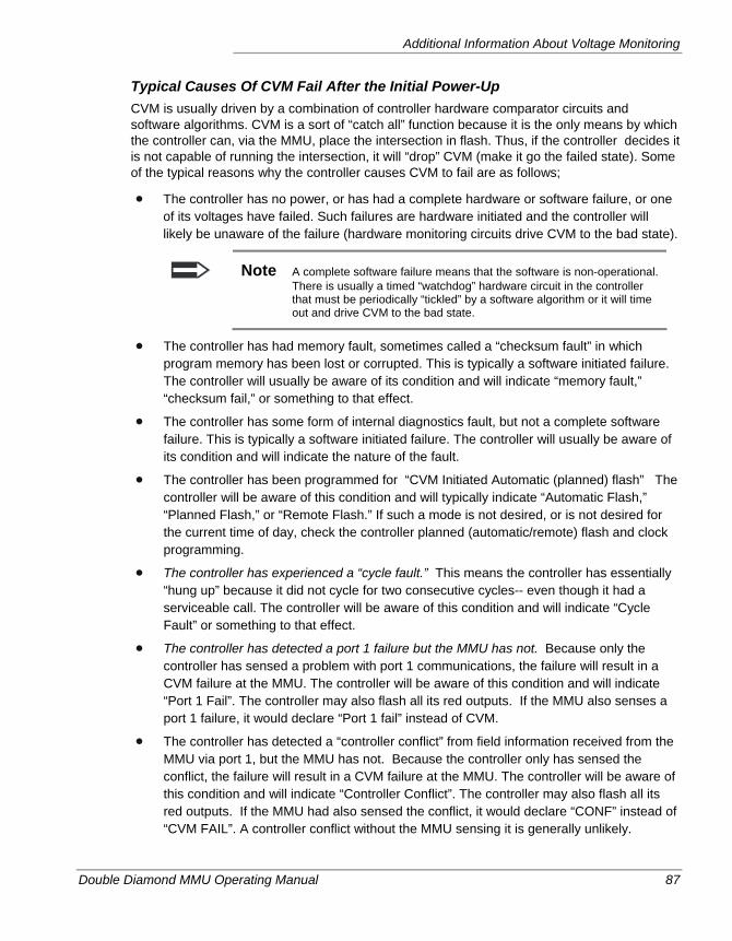
Additional Information About Voltage Monitoring
Double Diamond MMU Operating Manual 87
Typical Causes Of CVM Fail After the Initial Power-Up CVM is usually driven by a combination of controller hardware comparator circuits and software algorithms. CVM is a sort of “catch all” function because it is the only means by which the controller can, via the MMU, place the intersection in flash. Thus, if the controller decides it is not capable of running the intersection, it will “drop” CVM (make it go the failed state). Some of the typical reasons why the controller causes CVM to fail are as follows;
The controller has no power, or has had a complete hardware or software failure, or one of its voltages have failed. Such failures are hardware initiated and the controller will likely be unaware of the failure (hardware monitoring circuits drive CVM to the bad state).
Note A complete software failure means that the software is non-operational. There is usually a timed “watchdog” hardware circuit in the controller that must be periodically “tickled” by a software algorithm or it will time out and drive CVM to the bad state.
The controller has had memory fault, sometimes called a “checksum fault” in which program memory has been lost or corrupted. This is typically a software initiated failure. The controller will usually be aware of its condition and will indicate “memory fault,” “checksum fail,” or something to that effect.
The controller has some form of internal diagnostics fault, but not a complete software failure. This is typically a software initiated failure. The controller will usually be aware of its condition and will indicate the nature of the fault.
The controller has been programmed for “CVM Initiated Automatic (planned) flash” The controller will be aware of this condition and will typically indicate “Automatic Flash,” “Planned Flash,” or “Remote Flash.” If such a mode is not desired, or is not desired for the current time of day, check the controller planned (automatic/remote) flash and clock programming.
The controller has experienced a “cycle fault.” This means the controller has essentially “hung up” because it did not cycle for two consecutive cycles-- even though it had a serviceable call. The controller will be aware of this condition and will indicate “Cycle Fault” or something to that effect.
The controller has detected a port 1 failure but the MMU has not. Because only the controller has sensed a problem with port 1 communications, the failure will result in a CVM failure at the MMU. The controller will be aware of this condition and will indicate “Port 1 Fail”. The controller may also flash all its red outputs. If the MMU also senses a port 1 failure, it would declare “Port 1 fail” instead of CVM.
The controller has detected a “controller conflict” from field information received from the MMU via port 1, but the MMU has not. Because the controller only has sensed the conflict, the failure will result in a CVM failure at the MMU. The controller will be aware of this condition and will indicate “Controller Conflict”. The controller may also flash all its red outputs. If the MMU had also sensed the conflict, it would declare “CONF” instead of “CVM FAIL”. A controller conflict without the MMU sensing it is generally unlikely.
Chapter 5 — CVM: Cabinet Voltage Monitoring
88 Double Diamond MMU Operating Manual
24VDC I or II Monitoring (Non-Latched or Latched) A second function in the “voltage monitor” portion of the MMU. The MMU monitors cabinet 24 volts via two inputs, where both must be above +22 VDC for normal operation. 24 VDC failure is similar to the CVM fail and is normally non-latched, but with a latch mode available by jumper on the Programming Card (or via keyboard when TS 1 card is inserted). In the non-latched mode, since the failure is a self healing failure, the unit can recover and exit flash unattended. The MMU will automatically energize its output relay anytime the controller is able to take +24VDC back to the “good state.” See the Fault Re-initialize option on page 66. When in the latch mode, like CVM, +24 VDC failures are not latched during the normal power-up routine, i.e.+24 VDC must first go to the “good” state before the latch mode is enabled. “24-2 FAIL” occurs similarly, but via a different input. Usually both voltage tests fail at the same time.
There is a 24VDC inhibit input (connector A) which disables the 24VDC monitor function. Note that this input should only be used if the MMU is used to monitor a non-DC controller assembly (with no 24VDC supply) such as an electromechanical controller.
Double Diamond MMU Operating Manual 89
Chapter 6 — Additional Monitoring/Unit Configuration Options
This chapter describes the additional monitoring capabilities of the Double Diamond MMU, in particular its self-monitoring functions. The following topics are discussed in detail in this chapter:
• Self-monitoring overview, on page 90.
• Fault displays used to indicate self-monitored faults, on page 92.
Chapter 6 — Additional Monitoring/Unit Configuration Options
90 Double Diamond MMU Operating Manual
OVERVIEW This chapter provides some more details about several of the Double Diamond’s self-monitoring and unit-configuration options.
Fault Reinitialization The Fault reinitialize option pertains to either type 12 or type 16 mode and causes the Double Diamond MMU to reinitialize the controller after a fault has been cleared. It does this by dropping its start delay relay for 1 second. By doing so, the controller will revert to its initialization phase and interval for a proper transition from flash to automatic operation. This is particularly beneficial on “self-healing” faults such as CVM or +24V (when those faults are not configured to operate as latched faults.) Once bad, these faults can automatically recover in the field while unattended. Without this fault reinitialize option, such recoveries could otherwise cause the cabinet to transfer from flash to any arbitrary set of field signals, depending on the interval the controller happens to be in at the time.
Configuring Fault Reinitialization Fault Reinitialization can be enabled from the menu system by navigating to Main Menu > Config > Monitor > Per Unit > screen 1 and setting Fault Reinit to one of the three single-digit numerical codes.
When option code 0 is invoked, the unit will exit flash immediately with no fault re-initialization.
When option code 1 invoked, the re-initialization process occurs after a manual reset or after a self-healing fault is cleared.
When option code 2 invoked, the re-initialization process occurs after a self-healing fault (such as CVM or +24V) clears but not after a manual or input reset. It is then incumbent upon the field technician to reset the intersection in the proper fashion.
Fault re-initialize should only be used if the cabinet is not otherwise configured to provide this capability, such as in Type 16 mode with a controller that responds properly to the Port 1 Start-Up Flash Call bit, or in a controller cabinet with an R/C pulse circuit from the MMU output relay to external start (see page 56).
Watchdog Status Monitoring When enabled (1), the S pin on connector B must continuously toggle ON and OFF or else a Watchdog Fault will occur. This input is typically driven by controller Flashing Logic out. Since this is not necessarily a standard wiring configuration, do not enable Watchdog unless the cabinet is specifically wired for it.
Port 1 Monitoring In the type 16 mode, if port 1 has not been defeated (see port 1 disable below), the MMU must be in constant communications with the controller. If the MMU does receive a Type 0 command frame from the controller for a period of 300 milliseconds, a port 1 failure will be declared by the MMU and the output relay will drop. This is a latched failure, requiring manual reset.
Overview
Double Diamond MMU Operating Manual 91
Port 1 Disable Input Monitoring In the type 16 mode, port 1 can be defeated by grounding the Port 1 disable pin in the Port 1 connector (pin 10--see page 123). When defeated, the MMU will operate in the 16 channel configuration but without requirement of Port 1 communications.
Type Monitoring The MMU type (12 or 16) is determined by MMU Port A connector pin HH. If the input changes state, the reset key must be manually pressed once to initially configure the Double Diamond for the new type. This prevents the unit from inadvertently changing states on its own in the field due to a field input change (say due to a bad input or weak connection). Thus, if the type (pin HH) changes but the Double Diamond MMU is still configured the old way (i.e. it has not been manually reset since the change) then a TYPE FAIL will be registered. This is a latched failure, requiring manual reset, which will re-configure it.
Programming Card Monitoring Whether or not the Programming Card has any jumpers, it must be inserted and properly seated into the MMU. If unable to detect the presence of the card, a “Card Failure” will be declared by the MMU and the output relay will drop. This is a latched failure, requiring manual reset. A “Card Fail” also occurs if two cards are inserted (only one allowed) or if a TS 1 card is inserted when the Type 16 mode is selected (pin A-HH = Logic ground true).
Field Check Monitoring This monitoring feature requires type 16 mode operation and port 1 enabled. It is an optional fault that must be enabled via keyboard programming. Selected channels must also be enabled. If so enabled, the AC signals as seen by the Double Diamond MMU, when red enable is active and type 0 load switch flash bit is not active, are then continuously compared with the port 1 Type 0 message sent by the controller (LS driver bits). If these bits do not match the selected channels for 10 consecutive messages, and there are no other failures registered*, a “Field Check” failure is registered. Bit #67 (spare bit #1) of the Type 129 response frame will be set to indicate a field check fault has been detected. This monitoring feature is disabled when in flash or signals off, i.e. when red enable is off or the type 0 load switch flash bit (112) is on. This is a latched failure, requiring manual reset.
*Field check faults are subordinate to all other failure modes such as conflict, red fail, etc. If another such fault is registered, it will take precedence on the display. The Field (check) Fault LED may still come on though. (See page 22.)
Diagnostics Fail The Double Diamond MMU has a built in set of internal diagnostic routines that continually self-test major components. These tests must pass for the unit to be considered functional. Should any critical portion of the diagnostics routine fail, a diagnostics fail is registered. This is a latched failure, requiring manual reset.
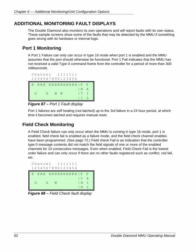
Chapter 6 — Additional Monitoring/Unit Configuration Options
92 Double Diamond MMU Operating Manual
ADDITIONAL MONITORING FAULT DISPLAYS The Double Diamond also monitors its own operations and will report faults with its own status. These sample screens show some of the faults that may be detected by the MMU if something goes wrong with its hardware or internal logic.
Port 1 Monitoring A Port 1 Failure can only can occur in type 16 mode when port 1 is enabled and the MMU assumes that the port should otherwise be functional. Port 1 Fail indicates that the MMU has not received a valid Type 0 command frame from the controller for a period of more than 300 milliseconds.
C h a n n e l 1 1 1 1 1 1 1 1 2 3 4 5 6 7 8 9 0 1 2 3 4 5 6
R R R R R R R R R R R R R R | P F | R A G G W W | T I | 1 L
Figure 87 – Port 1 Fault display
Port 1 failures are self healing (not latched) up to the 3rd failure in a 24 hour period, at which time it becomes latched and requires manual reset.
Field Check Monitoring A Field Check failure can only occur when the MMU is running in type 16 mode, port 1 is enabled, field check fail is enabled as a failure mode, and the field check channel enables have been programmed. (See page 72.) Field check Fail is an indication that the controller type 0 message contents did not match the field signals of one or more of the enabled channels for 10 consecutive messages. Even when enabled, Field Check Fail is the lowest order failure and can only occur if there are no other faults registered such as conflict, red fail, etc.
C h a n n e l 1 1 1 1 1 1 1 1 2 3 4 5 6 7 8 9 0 1 2 3 4 5 6
R R R R R R R R R R R R R R | F F | C A G G W | H I | K L
Figure 88 – Field Check fault display
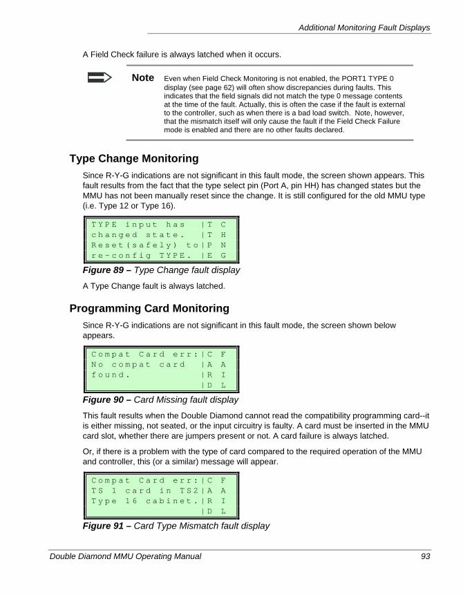
Additional Monitoring Fault Displays
Double Diamond MMU Operating Manual 93
A Field Check failure is always latched when it occurs.
Note Even when Field Check Monitoring is not enabled, the PORT1 TYPE 0 display (see page 62) will often show discrepancies during faults. This indicates that the field signals did not match the type 0 message contents at the time of the fault. Actually, this is often the case if the fault is external to the controller, such as when there is a bad load switch. Note, however, that the mismatch itself will only cause the fault if the Field Check Failure mode is enabled and there are no other faults declared.
Type Change Monitoring Since R-Y-G indications are not significant in this fault mode, the screen shown appears. This fault results from the fact that the type select pin (Port A, pin HH) has changed states but the MMU has not been manually reset since the change. It is still configured for the old MMU type (i.e. Type 12 or Type 16).
T Y P E i n p u t h a s | T C c h a n g e d s t a t e . | T H R e s e t ( s a f e l y ) t o | P N r e - c o n f i g T Y P E . | E G
Figure 89 – Type Change fault display
A Type Change fault is always latched.
Programming Card Monitoring Since R-Y-G indications are not significant in this fault mode, the screen shown below appears.
C o m p a t C a r d e r r : | C F N o c o m p a t c a r d | A A f o u n d . | R I | D L
Figure 90 – Card Missing fault display
This fault results when the Double Diamond cannot read the compatibility programming card--it is either missing, not seated, or the input circuitry is faulty. A card must be inserted in the MMU card slot, whether there are jumpers present or not. A card failure is always latched.
Or, if there is a problem with the type of card compared to the required operation of the MMU and controller, this (or a similar) message will appear.
C o m p a t C a r d e r r : | C F T S 1 c a r d i n T S 2 | A A T y p e 1 6 c a b i n e t . | R I | D L
Figure 91 – Card Type Mismatch fault display
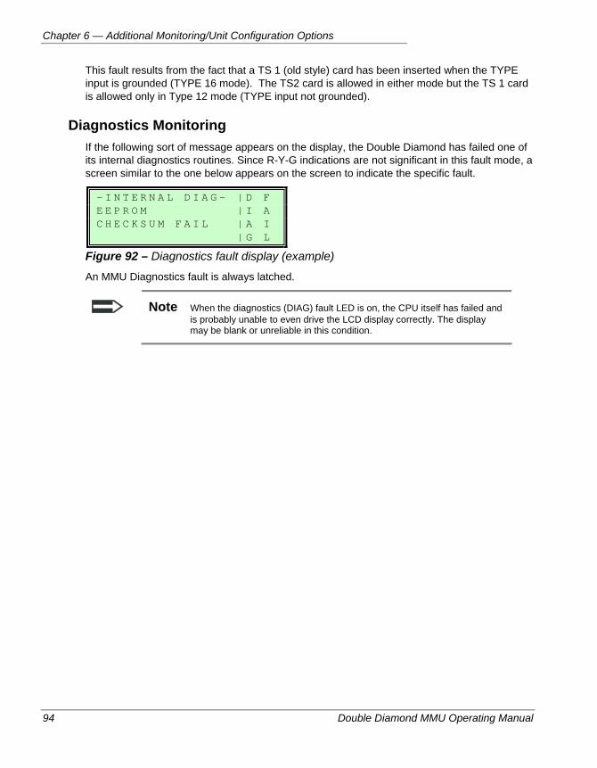
Chapter 6 — Additional Monitoring/Unit Configuration Options
94 Double Diamond MMU Operating Manual
This fault results from the fact that a TS 1 (old style) card has been inserted when the TYPE input is grounded (TYPE 16 mode). The TS2 card is allowed in either mode but the TS 1 card is allowed only in Type 12 mode (TYPE input not grounded).
Diagnostics Monitoring If the following sort of message appears on the display, the Double Diamond has failed one of its internal diagnostics routines. Since R-Y-G indications are not significant in this fault mode, a screen similar to the one below appears on the screen to indicate the specific fault.
- I N T E R N A L D I A G - | D F E E P R O M | I A C H E C K S U M F A I L | A I | G L
Figure 92 – Diagnostics fault display (example)
An MMU Diagnostics fault is always latched.
Note When the diagnostics (DIAG) fault LED is on, the CPU itself has failed and is probably unable to even drive the LCD display correctly. The display may be blank or unreliable in this condition.
Double Diamond MMU Operating Manual 95
Chapter 7 — Event Logs and Replay Mode
This chapter describes the Double Diamond’s historical investigation tools, particularly its voltage, blink and event logs, and its replay capabilities. The following topics are discussed in detail in this chapter:
• Using the voltage log, on page 96.
• Using the blink log, on page 99.
• Using the Event Log, on page 100.
• Uploading logs to a PC, on page 106.
• Using Replay mode is described starting on page 107.
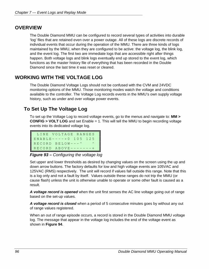
Chapter 7 — Event Logs and Replay Mode
96 Double Diamond MMU Operating Manual
OVERVIEW The Double Diamond MMU can be configured to record several types of activities into durable ‘log’ files that are retained even over a power outage. All of these logs are discrete records of individual events that occur during the operation of the MMU. There are three kinds of logs maintained by the MMU, when they are configured to be active: the voltage log, the blink log, and the event log. The first two are immediate logs that are accessible right after things happen. Both voltage logs and blink logs eventually end up stored to the event log, which functions as the master history file of everything that has been recorded in the Double Diamond since the last time it was reset or cleared.
WORKING WITH THE VOLTAGE LOG The Double Diamond Voltage Logs should not be confused with the CVM and 24VDC monitoring options of the MMU. Those monitoring modes watch the voltage and conditions available to the controller. The Voltage Log records events in the MMU’s own supply voltage history, such as under and over voltage power events.
To Set Up The Voltage Log To set up the Voltage Log to record voltage events, go to the menus and navigate to: MM > CONFIG > VOLT LOG and set Enable = 1. This will tell the MMU to begin recording voltage events into its dedicated voltage log.
L I N E V O L T A G E R A N G E S E N A B L E - - - - > 0 1 0 5 1 2 5 R E C O R D B E L O W - - - ^ ^ R E C O R D A B O V E - - - - - - - +
Figure 93 – Configuring the voltage log
Set upper and lower thresholds as desired by changing values on the screen using the up and down arrow buttons. The factory defaults for low and high voltage events are 105VAC and 125VAC (RMS) respectively. The unit will record if values fall outside this range. Note that this is a log only and not a fault by itself. Values outside these ranges do not trip the MMU (or cause flash) unless the unit is otherwise unable to operate or some other fault is caused as a result.
A voltage record is opened when the unit first senses the AC line voltage going out of range based on the set-up values.
A voltage record is closed when a period of 5 consecutive minutes goes by without any out of range values registered.
When an out of range episode occurs, a record is stored in the Double Diamond MMU voltage log. The message that appear in the voltage log includes the end of the voltage event as shown in Figure 94.
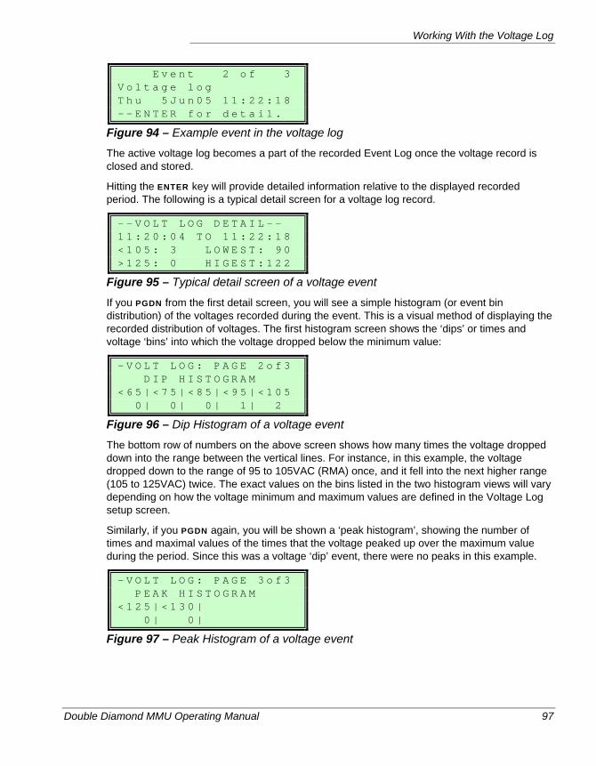
Working With the Voltage Log
Double Diamond MMU Operating Manual 97
E v e n t 2 o f 3 V o l t a g e l o g T h u 5 J u n 0 5 1 1 : 2 2 : 1 8 - - E N T E R f o r d e t a i l .
Figure 94 – Example event in the voltage log
The active voltage log becomes a part of the recorded Event Log once the voltage record is closed and stored.
Hitting the ENTER key will provide detailed information relative to the displayed recorded period. The following is a typical detail screen for a voltage log record.
- - V O L T L O G D E T A I L - - 1 1 : 2 0 : 0 4 T O 1 1 : 2 2 : 1 8 < 1 0 5 : 3 L O W E S T : 9 0 > 1 2 5 : 0 H I G E S T : 1 2 2
Figure 95 – Typical detail screen of a voltage event
If you PGDN from the first detail screen, you will see a simple histogram (or event bin distribution) of the voltages recorded during the event. This is a visual method of displaying the recorded distribution of voltages. The first histogram screen shows the ‘dips’ or times and voltage ‘bins’ into which the voltage dropped below the minimum value:
- V O L T L O G : P A G E 2 o f 3 D I P H I S T O G R A M < 6 5 | < 7 5 | < 8 5 | < 9 5 | < 1 0 5 0 | 0 | 0 | 1 | 2
Figure 96 – Dip Histogram of a voltage event
The bottom row of numbers on the above screen shows how many times the voltage dropped down into the range between the vertical lines. For instance, in this example, the voltage dropped down to the range of 95 to 105VAC (RMA) once, and it fell into the next higher range (105 to 125VAC) twice. The exact values on the bins listed in the two histogram views will vary depending on how the voltage minimum and maximum values are defined in the Voltage Log setup screen.
Similarly, if you PGDN again, you will be shown a ‘peak histogram’, showing the number of times and maximal values of the times that the voltage peaked up over the maximum value during the period. Since this was a voltage ‘dip’ event, there were no peaks in this example.
- V O L T L O G : P A G E 3 o f 3 P E A K H I S T O G R A M < 1 2 5 | < 1 3 0 | 0 | 0 |
Figure 97 – Peak Histogram of a voltage event
Chapter 7 — Event Logs and Replay Mode
98 Double Diamond MMU Operating Manual
Viewing Voltage Logs Once Recorded Once a voltage log has been closed it goes to the event log and can be viewed in the event log by hitting ENTER from a voltage log event screen, or by going to the Event Log viewing area of the menus. (Refer to page 100 for instructions on viewing event logs.) The voltage log screens in the message log will appear exactly as shown in the previous section, except that they are a static recording from some time in the past (i.e. they do not change).
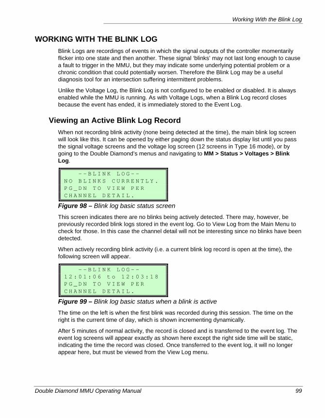
Working With the Blink Log
Double Diamond MMU Operating Manual 99
WORKING WITH THE BLINK LOG Blink Logs are recordings of events in which the signal outputs of the controller momentarily flicker into one state and then another. These signal ‘blinks’ may not last long enough to cause a fault to trigger in the MMU, but they may indicate some underlying potential problem or a chronic condition that could potentially worsen. Therefore the Blink Log may be a useful diagnosis tool for an intersection suffering intermittent problems.
Unlike the Voltage Log, the Blink Log is not configured to be enabled or disabled. It is always enabled while the MMU is running. As with Voltage Logs, when a Blink Log record closes because the event has ended, it is immediately stored to the Event Log.
Viewing an Active Blink Log Record When not recording blink activity (none being detected at the time), the main blink log screen will look like this. It can be opened by either paging down the status display list until you pass the signal voltage screens and the voltage log screen (12 screens in Type 16 mode), or by going to the Double Diamond’s menus and navigating to MM > Status > Voltages > Blink Log.
- - B L I N K L O G - - N O B L I N K S C U R R E N T L Y . P G _ D N T O V I E W P E R C H A N N E L D E T A I L .
Figure 98 – Blink log basic status screen
This screen indicates there are no blinks being actively detected. There may, however, be previously recorded blink logs stored in the event log. Go to View Log from the Main Menu to check for those. In this case the channel detail will not be interesting since no blinks have been detected.
When actively recording blink activity (i.e. a current blink log record is open at the time), the following screen will appear.
- - B L I N K L O G - - 1 2 : 0 1 : 0 6 t o 1 2 : 0 3 : 1 8 P G _ D N T O V I E W P E R C H A N N E L D E T A I L .
Figure 99 – Blink log basic status when a blink is active
The time on the left is when the first blink was recorded during this session. The time on the right is the current time of day, which is shown incrementing dynamically.
After 5 minutes of normal activity, the record is closed and is transferred to the event log. The event log screens will appear exactly as shown here except the right side time will be static, indicating the time the record was closed. Once transferred to the event log, it will no longer appear here, but must be viewed from the View Log menu.
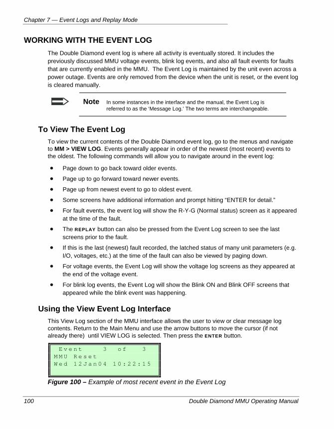
Chapter 7 — Event Logs and Replay Mode
100 Double Diamond MMU Operating Manual
WORKING WITH THE EVENT LOG The Double Diamond event log is where all activity is eventually stored. It includes the previously discussed MMU voltage events, blink log events, and also all fault events for faults that are currently enabled in the MMU. The Event Log is maintained by the unit even across a power outage. Events are only removed from the device when the unit is reset, or the event log is cleared manually.
Note In some instances in the interface and the manual, the Event Log is referred to as the ‘Message Log.’ The two terms are interchangeable.
To View The Event Log To view the current contents of the Double Diamond event log, go to the menus and navigate to MM > VIEW LOG. Events generally appear in order of the newest (most recent) events to the oldest. The following commands will allow you to navigate around in the event log:
Page down to go back toward older events.
Page up to go forward toward newer events.
Page up from newest event to go to oldest event.
Some screens have additional information and prompt hitting “ENTER for detail.”
For fault events, the event log will show the R-Y-G (Normal status) screen as it appeared at the time of the fault.
The REPLAY button can also be pressed from the Event Log screen to see the last screens prior to the fault.
If this is the last (newest) fault recorded, the latched status of many unit parameters (e.g. I/O, voltages, etc.) at the time of the fault can also be viewed by paging down.
For voltage events, the Event Log will show the voltage log screens as they appeared at the end of the voltage event.
For blink log events, the Event Log will show the Blink ON and Blink OFF screens that appeared while the blink event was happening.
Using the View Event Log Interface This View Log section of the MMU interface allows the user to view or clear message log contents. Return to the Main Menu and use the arrow buttons to move the cursor (if not already there) until VIEW LOG is selected. Then press the ENTER button.
E v e n t 3 o f 3 M M U R e s e t W e d 1 2 J a n 0 4 1 0 : 2 2 : 1 5
Figure 100 – Example of most recent event in the Event Log
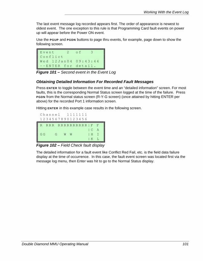
Working With the Event Log
Double Diamond MMU Operating Manual 101
The last event message log recorded appears first. The order of appearance is newest to oldest event. The one exception to this rule is that Programming Card fault events on power up will appear before the Power ON event.
Use the PGUP and PGDN buttons to page thru events, for example, page down to show the following screen.
E v e n t 2 o f 3 C o n f l i c t W e d 1 2 J a n 0 4 0 9 : 4 3 : 4 4 - - E N T E R f o r d e t a i l .
Figure 101 – Second event in the Event Log
Obtaining Detailed Information For Recorded Fault Messages Press ENTER to toggle between the event time and an “detailed information” screen. For most faults, this is the corresponding Normal Status screen logged at the time of the failure. Press PGDN from the Normal status screen (R-Y-G screen) (once attained by hitting ENTER per above) for the recorded Port 1 information screen.
Hitting ENTER in this example case results in the following screen.
C h a n n e l 1 1 1 1 1 1 1 1 2 3 4 5 6 7 8 9 0 1 2 3 4 5 6
R R R R R R R R R R R R R R | F F | C A G G G W W | H I | K L
Figure 102 – Field Check fault display
The detailed information for a fault event like Conflict Red Fail, etc. is the field data failure display at the time of occurrence. In this case, the fault event screen was located first via the message log menu, then Enter was hit to go to the Normal Status display.
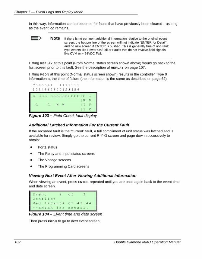
Chapter 7 — Event Logs and Replay Mode
102 Double Diamond MMU Operating Manual
In this way, information can be obtained for faults that have previously been cleared—as long as the event log remains.
Note If there is no pertinent additional information relative to the original event screen, the bottom line of the screen will not indicate “ENTER for Detail” and no new screen if ENTER is pushed. This is generally true of non-fault type events like Power On/Fail or Faults that do not involve field signals like CVM or + 24VDC Fail.
Hitting REPLAY at this point (From Normal status screen shown above) would go back to the last screen prior to this fault. See the description of REPLAY on page 107.
Hitting PGDN at this point (Normal status screen shown) results in the controller Type 0 information at the time of failure (the information is the same as described on page 62).
C h a n n e l 1 1 1 1 1 1 1 1 2 3 4 5 6 7 8 9 0 1 2 3 4 5 6
R R R R R R R R R R R R R R | P I | R N G G W W | T F | 1 O
Figure 103 – Field Check fault display
Additional Latched Information For the Current Fault If the recorded fault is the “current” fault, a full compliment of unit status was latched and is available for review. Simply go the current R-Y-G screen and page down successively to obtain:
Port1 status
The Relay and Input status screens
The Voltage screens
The Programming Card screens
Viewing Next Event After Viewing Additional Information When viewing an event, press ENTER repeated until you are once again back to the event time and date screen.
E v e n t 2 o f 3 C o n f l i c t W e d 1 2 J a n 0 4 0 9 : 4 3 : 4 4 - - E N T E R f o r d e t a i l .
Figure 104 – Event time and date screen
Then press PGDN to go to next event screen.
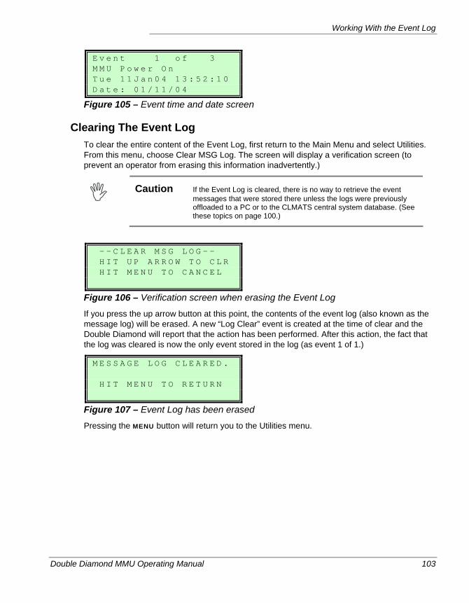
Working With the Event Log
Double Diamond MMU Operating Manual 103
E v e n t 1 o f 3 M M U P o w e r O n T u e 1 1 J a n 0 4 1 3 : 5 2 : 1 0 D a t e : 0 1 / 1 1 / 0 4
Figure 105 – Event time and date screen
Clearing The Event Log To clear the entire content of the Event Log, first return to the Main Menu and select Utilities. From this menu, choose Clear MSG Log. The screen will display a verification screen (to prevent an operator from erasing this information inadvertently.)
Caution If the Event Log is cleared, there is no way to retrieve the event
messages that were stored there unless the logs were previously offloaded to a PC or to the CLMATS central system database. (See these topics on page 100.)
- - C L E A R M S G L O G - - H I T U P A R R O W T O C L R H I T M E N U T O C A N C E L
Figure 106 – Verification screen when erasing the Event Log
If you press the up arrow button at this point, the contents of the event log (also known as the message log) will be erased. A new “Log Clear” event is created at the time of clear and the Double Diamond will report that the action has been performed. After this action, the fact that the log was cleared is now the only event stored in the log (as event 1 of 1.)
M E S S A G E L O G C L E A R E D . H I T M E N U T O R E T U R N
Figure 107 – Event Log has been erased
Pressing the MENU button will return you to the Utilities menu.
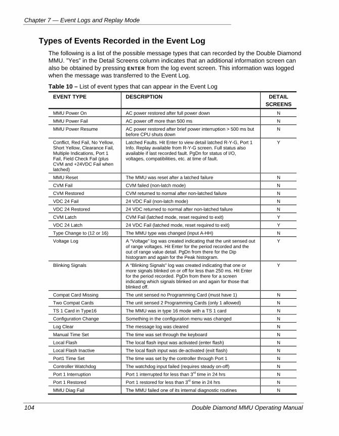
Chapter 7 — Event Logs and Replay Mode
104 Double Diamond MMU Operating Manual
Types of Events Recorded in the Event Log The following is a list of the possible message types that can recorded by the Double Diamond MMU. ”Yes” in the Detail Screens column indicates that an additional information screen can also be obtained by pressing ENTER from the log event screen. This information was logged when the message was transferred to the Event Log.
Table 10 – List of event types that can appear in the Event Log EVENT TYPE DESCRIPTION DETAIL
SCREENS MMU Power On AC power restored after full power down N
MMU Power Fail AC power off more than 500 ms N
MMU Power Resume AC power restored after brief power interruption > 500 ms but before CPU shuts down
N
Conflict, Red Fail, No Yellow, Short Yellow, Clearance Fail, Multiple Indications, Port 1 Fail, Field Check Fail (plus CVM and +24VDC Fail when latched)
Latched Faults. Hit Enter to view detail latched R-Y-G, Port 1 Info. Replay available from R-Y-G screen. Full status also available if last recorded fault. PgDn for status of I/O, voltages, compatibilities, etc. at time of fault.
Y
MMU Reset The MMU was reset after a latched failure N
CVM Fail CVM failed (non-latch mode) N
CVM Restored CVM returned to normal after non-latched failure N
VDC 24 Fail 24 VDC Fail (non-latch mode) N
VDC 24 Restored 24 VDC returned to normal after non-latched failure N
CVM Latch CVM Fail (latched mode, reset required to exit) Y
VDC 24 Latch 24 VDC Fail (latched mode, reset required to exit) Y
Type Change to (12 or 16) The MMU type was changed (input A-HH) N
Voltage Log A “Voltage” log was created indicating that the unit sensed out of range voltages. Hit Enter for the period recorded and the out of range value detail. PgDn from there for the Dip histogram and again for the Peak histogram.
Y
Blinking Signals A “Blinking Signals” log was created indicating that one or more signals blinked on or off for less than 250 ms. Hit Enter for the period recorded. PgDn from there for a screen indicating which signals blinked on and again for those that blinked off.
Y
Compat Card Missing The unit sensed no Programming Card (must have 1) N
Two Compat Cards The unit sensed 2 Programming Cards (only 1 allowed) N
TS 1 Card in Type16 The MMU was in type 16 mode with a TS 1 card N
Configuration Change Something in the configuration menu was changed N
Log Clear The message log was cleared N
Manual Time Set The time was set through the keyboard N
Local Flash The local flash input was activated (enter flash) N
Local Flash Inactive The local flash input was de-activated (exit flash) N
Port1 Time Set The time was set by the controller through Port 1 N
Controller Watchdog The watchdog input failed (requires steady on-off) N
Port 1 Interruption Port 1 interrupted for less than 3rd time in 24 hrs N
Port 1 Restored Port 1 restored for less than 3rd time in 24 hrs N
MMU Diag Fail The MMU failed one of its internal diagnostic routines N
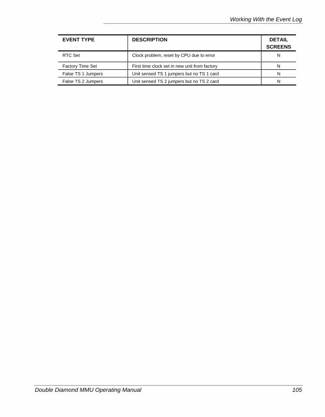
Working With the Event Log
Double Diamond MMU Operating Manual 105
EVENT TYPE DESCRIPTION DETAIL SCREENS
RTC Set Clock problem, reset by CPU due to error N
Factory Time Set First time clock set in new unit from factory N
False TS 1 Jumpers Unit sensed TS 1 jumpers but no TS 1 card N
False TS 2 Jumpers Unit sensed TS 2 jumpers but no TS 2 card N
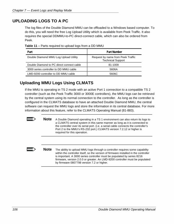
Chapter 7 — Event Logs and Replay Mode
106 Double Diamond MMU Operating Manual
UPLOADING LOGS TO A PC The log files of the Double Diamond MMU can be offloaded to a Windows based computer. To do this, you will need the free Log Upload Utility which is available from Peek Traffic. It also requires the special DDMMU-to-PC direct-connect cable, which can also be ordered from Peek.
Table 11 – Parts required to upload logs from a DD MMU
Part Part Number Double Diamond MMU Log Upload Utility Request by name from Peek Traffic
Technical Support Double Diamond to PC direct connect cable 81-1009 3000 series controller to DD MMU cable 5606A LMD-9200 controller to DD MMU cable 5606C
Uploading MMU Logs Using CLMATS If the MMU is operating in TS 2 mode with an active Port 1 connection to a compatible TS 2 controller (such as the Peek Traffic 3000 or 3000E controllers), the MMU logs can be retrieved by the central system using its normal connection to the controller. As long as the controller is configured in the CLMATS database to have an attached Double Diamond MMU, the central software can request the MMU logs and store the information in its central database. For more information about this feature, refer to the CLMATS Operating Manual (81-883).
Note A Double Diamond operating in a TS 1 environment can also return its logs to a CLMATS central system in this same manner as long as it is connected to the controller over its serial port. (i.e. a serial cable connects the controller’s Port 2 to the MMU’s RS-232 port.) CLMATS version 7.2.12 or higher is required for this operation.
Note The ability to upload MMU logs through a controller requires some capability within the controller itself, so the version of firmware installed in the controller is important. A 3000 series controller must be populated by series 8216 firmware, version 2.0.0 or greater. An LMD-9200 controller must be populated by firmware 0807798 version 7.2 or higher.
Replay Mode
Double Diamond MMU Operating Manual 107
REPLAY MODE
During normal operation, the Double Diamond MMU constantly stores the last 20 Normal Status screen changes in a special area of memory called the “Replay Stack”. If no failures occur, the current replay stack is constantly refreshed by each display change such that the most recent display enters the top of the stack. This pushes all previously stored screens down one location in the stack and the oldest is pushed off the bottom. If a fault occurs, the whole replay stack freezes and immediately gets loaded into a historical memory location that stays with that fault log for future play back. This log remains until it is cleared by the user or it gets overwritten by newer fault event.
Using the Replay Feature 1. To start the replay, first get to the desired R-Y-G screen, then press the REPLAY key.
If it is desired to use the feature on a currently displayed fault, press the Replay button while displaying the fault (which is the current Normal Status screen). It goes back to most recent screen prior to the fault. The Replay stack was automatically frozen at the time of fault.
If it is desired to use the feature on a historically recorded fault (not currently displayed),
a.) Use the message log menu to find the time and date event log screen of that fault.
b.) Hit ENTER when the desired event screen is displayed to go to the R-Y-G display of that recorded fault (Hitting ENTER brings additional info relative to an event log--the Normal Status screen in this case.)
c.) Press the Replay button while displaying the Normal Status screen as selected above. It goes back to the most recent screen prior to that fault. PGDN once to see each prior screen.
2. Once the Replay key has been pushed as above, it will go the most previous screen prior and will indicate “LXX” on the right side of the display (where XX = 00-20). The recorded time value of the display duration is also shown. The recorded time duration of each Replay screen is shown on the lower right portion of the display.
a.) To manually step through the screens, start by pressing PGDN once to go one screen back in history. Press PGDN again to go to one more screen back, etc. This process can be continued until the unit goes back as far as 20 screens. The PGUP button can be used to go one screen forward in history, eventually returning to the original fault screen.
b.) To exit the Replay mode, page up until the original displayed fault is shown or simply hit the REPLAY button from any of the REPLAY screens (but not the original screen.)
Note The display screen will automatically return to the Normal Status display after 10 minutes of keyboard inactivity.
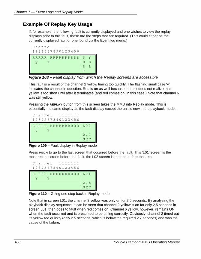
Chapter 7 — Event Logs and Replay Mode
108 Double Diamond MMU Operating Manual
Example Of Replay Key Usage If, for example, the following fault is currently displayed and one wishes to view the replay displays prior to this fault, these are the steps that are required. (This could either be the currently displayed fault or one found via the Event log menu.)
C h a n n e l 1 1 1 1 1 1 1 1 2 3 4 5 6 7 8 9 0 1 2 3 4 5 6
R R R R R R R R R R R R R R R | S Y y Y | H E | R L | T
Figure 108 – Fault display from which the Replay screens are accessible
This fault is a result of the channel 2 yellow timing too quickly. The flashing small case ‘y’ indicates the channel in question. Red is on as well because the unit does not realize that yellow is too short until after it terminates (and red comes on, in this case.) Note that channel 6 was still yellow.
Pressing the REPLAY button from this screen takes the MMU into Replay mode. This is essentially the same display as the fault display except the unit is now in the playback mode.
C h a n n e l 1 1 1 1 1 1 1 1 2 3 4 5 6 7 8 9 0 1 2 3 4 5 6
R R R R R R R R R R R R R R R | L 0 0 y Y | | 0 . 1 | S E C
Figure 109 – Fault display in Replay mode
Press PGDN to go to the last screen that occurred before the fault. This ‘L01’ screen is the most recent screen before the fault, the L02 screen is the one before that, etc.
C h a n n e l 1 1 1 1 1 1 1 1 2 3 4 5 6 7 8 9 0 1 2 3 4 5 6
R R R R R R R R R R R R R R | L 0 1 Y Y | | 2 . 5 | S E C
Figure 110 – Going one step back in Replay mode
Note that in screen L01, the channel 2 yellow was only on for 2.5 seconds. By analyzing the playback display sequence, it can be seen that channel 2 yellow is on for only 2.5 seconds in screen L01, then goes to fault when red comes on. Channel 6 yellow, however, remains ON when the fault occurred and is presumed to be timing correctly. Obviously, channel 2 timed out its yellow too quickly (only 2.5 seconds, which is below the required 2.7 seconds) and was the cause of the failure.
Replay Mode
Double Diamond MMU Operating Manual 109
The Replay mode can go up to L20 (that is, to the 20th previous screen.) For each screen:
PGDN goes one screen back in history
PGUP goes one screen forward toward the present
If the time value is from 0.0 to 9.9 seconds before the time of the fault, then it is shown in tenths of seconds. If the time stamp is from 10 to 255 seconds before the fault, it is shown to the nearest whole second. (A time of 255 indicates that the event occurred 255 seconds or greater before the fault.) The time value remains constant while the Replay screen is displayed.
Chapter 7 — Event Logs and Replay Mode
110 Double Diamond MMU Operating Manual
Double Diamond MMU Operating Manual 111
Chapter 8 — Security
This chapter describes the security capabilities of the Double Diamond MMU. The following topics are discussed in detail in this chapter:
• Using a security code, on page 112.
• Enabling the security system, on page 113.
Chapter 8 — Security
112 Double Diamond MMU Operating Manual
OVERVIEW The Double Diamond provides a rudimentary security system as part of its interface. When a non-zero four-digit code is specified as the ‘security code’, this code must be supplied by the operator before any changes to the MMU’s settings will be permitted.
SECURITY CODE The Double Diamond MMU provides a security code system that restricts data entry. The security code is a 4 digit user defined value. The disable value is 0000, which is also the factory ship mode. When set to the disable value, the security code is not relevant.
When the security code is set to other than 0000, the security code value must be entered prior to changing values. The security code is not required to simply view existing values.* However, a prompt screen requesting the security code is triggered whenever an attempt is made to change a value.
Security code access enables an editing ‘session’ that is lasts for the duration of the display light timing period, or in other words, you will be able to change settings in the interface as long as you keep pressing keys so that the interface remains ‘live’. This period lasts 5 minutes beyond the last time you press a button. Once the light goes out, the active session is closed and a new security code entry will be required to further change data.
The security code affects all CONFIG items (MONITOR, SET TIME, VOLT LOG), plus CLEAR MESSAGE LOG and DIAGNOSTICS.
Changing the Security Code The security code may be changed if the existing code is disabled (0000) or the old value has been entered for access.
If You Forget the Code A “back door” code is available that provides a way of accessing the unit when the security code is unknown. This consists of a function of the date and year that generates a number that can be cross-referenced to a code from a look-up table. This code will be valid for that day only. Contact Peek Traffic Technical Support if this code is needed.
Note Security codes are not given to distributors, so you will need to contact Peek Tech Support directly to request this information.
* Except for the Security Code Change screen itself. Access to this screen is denied until the current security
code is entered.
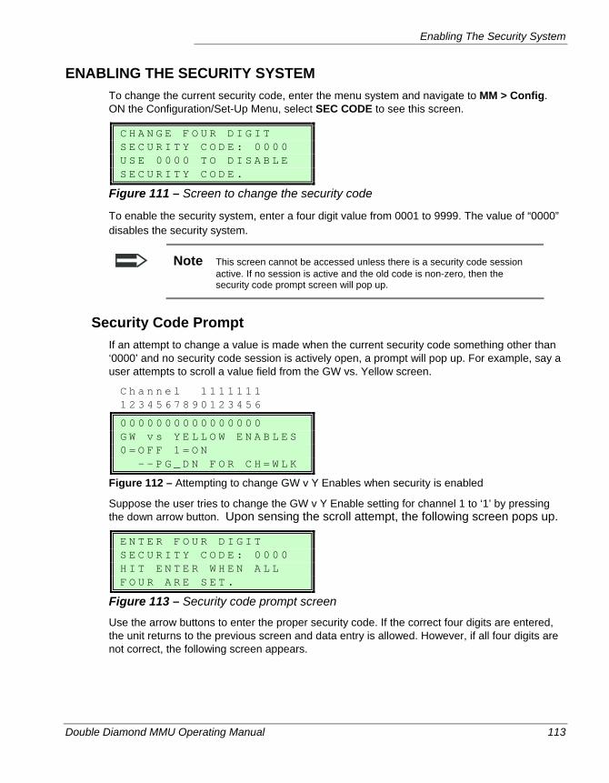
Enabling The Security System
Double Diamond MMU Operating Manual 113
ENABLING THE SECURITY SYSTEM To change the current security code, enter the menu system and navigate to MM > Config. ON the Configuration/Set-Up Menu, select SEC CODE to see this screen.
C H A N G E F O U R D I G I T S E C U R I T Y C O D E : 0 0 0 0 U S E 0 0 0 0 T O D I S A B L E S E C U R I T Y C O D E .
Figure 111 – Screen to change the security code
To enable the security system, enter a four digit value from 0001 to 9999. The value of “0000” disables the security system.
Note This screen cannot be accessed unless there is a security code session active. If no session is active and the old code is non-zero, then the security code prompt screen will pop up.
Security Code Prompt If an attempt to change a value is made when the current security code something other than ‘0000’ and no security code session is actively open, a prompt will pop up. For example, say a user attempts to scroll a value field from the GW vs. Yellow screen.
C h a n n e l 1 1 1 1 1 1 1 1 2 3 4 5 6 7 8 9 0 1 2 3 4 5 6
0 0 0 0 0 0 0 0 0 0 0 0 0 0 0 0 G W v s Y E L L O W E N A B L E S 0 = O F F 1 = O N - - P G _ D N F O R C H = W L K
Figure 112 – Attempting to change GW v Y Enables when security is enabled
Suppose the user tries to change the GW v Y Enable setting for channel 1 to ‘1’ by pressing the down arrow button. Upon sensing the scroll attempt, the following screen pops up.
E N T E R F O U R D I G I T S E C U R I T Y C O D E : 0 0 0 0 H I T E N T E R W H E N A L L F O U R A R E S E T .
Figure 113 – Security code prompt screen
Use the arrow buttons to enter the proper security code. If the correct four digits are entered, the unit returns to the previous screen and data entry is allowed. However, if all four digits are not correct, the following screen appears.
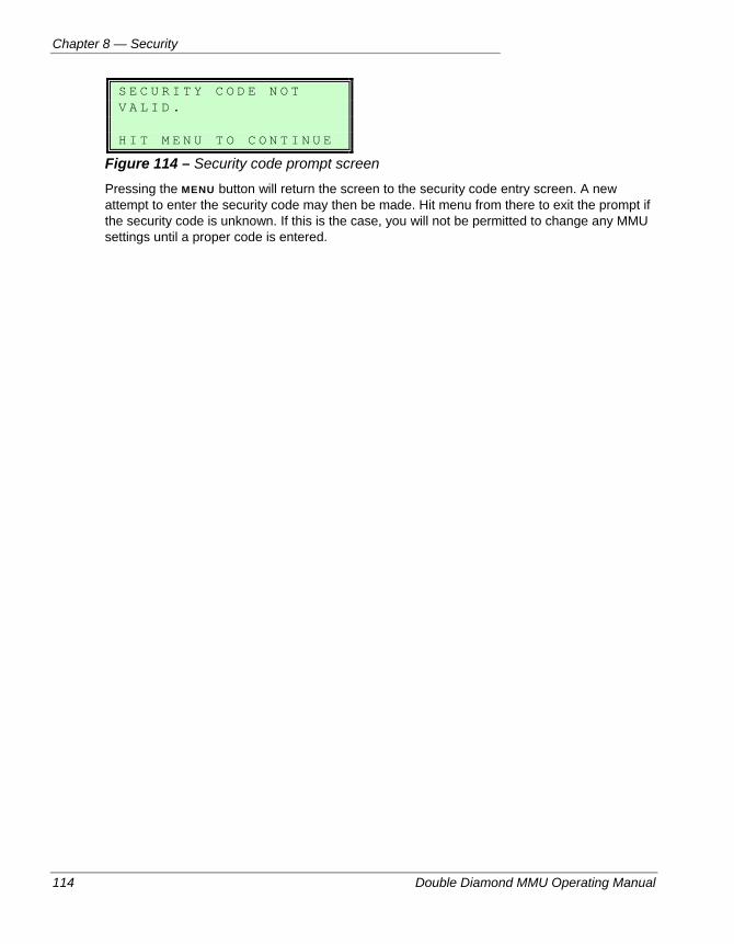
Chapter 8 — Security
114 Double Diamond MMU Operating Manual
S E C U R I T Y C O D E N O T V A L I D . H I T M E N U T O C O N T I N U E
Figure 114 – Security code prompt screen
Pressing the MENU button will return the screen to the security code entry screen. A new attempt to enter the security code may then be made. Hit menu from there to exit the prompt if the security code is unknown. If this is the case, you will not be permitted to change any MMU settings until a proper code is entered.
Double Diamond MMU Operating Manual 115
Chapter 9 — Technical Details
This chapter provides more technical details about the hardware and factory setup of the Double Diamond, including factory default settings and the pin-assignments of the various front panel ports of the unit. The following topics are discussed in detail in this chapter:
• Double Diamond Specifications, on page 116.
• Port A pin assignments, on page 119.
• Port B pin assignments, on page 121.
• Port 1 pin assignments and other details, on page 122.
• RS-232 pin assignments and other details, on page 124.
• Pre-set configurations available in the firmware, on page 125.
• Priority requirements of faults, on page 128.
• Charts for recording current settings and the factory defaults, on page 129.
• Notes about the compatibility of the Double Diamond to the LSM/LNM/ELRA and ELRB monitors, on page 131.
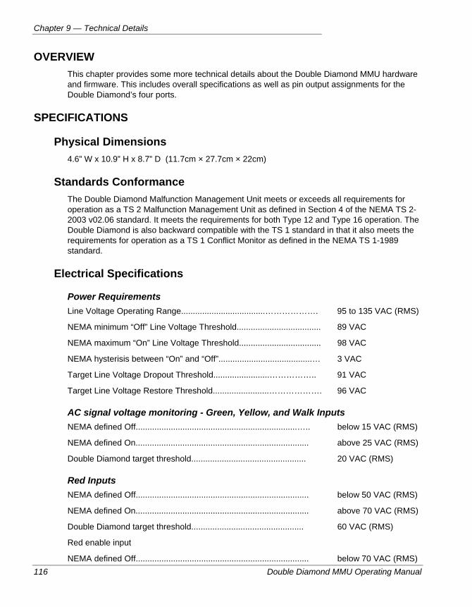
Chapter 9 — Technical Details
116 Double Diamond MMU Operating Manual
OVERVIEW This chapter provides some more technical details about the Double Diamond MMU hardware and firmware. This includes overall specifications as well as pin output assignments for the Double Diamond’s four ports.
SPECIFICATIONS
Physical Dimensions 4.6” W x 10.9” H x 8.7” D (11.7cm × 27.7cm × 22cm)
Standards Conformance The Double Diamond Malfunction Management Unit meets or exceeds all requirements for operation as a TS 2 Malfunction Management Unit as defined in Section 4 of the NEMA TS 2-2003 v02.06 standard. It meets the requirements for both Type 12 and Type 16 operation. The Double Diamond is also backward compatible with the TS 1 standard in that it also meets the requirements for operation as a TS 1 Conflict Monitor as defined in the NEMA TS 1-1989 standard.
Electrical Specifications
Power Requirements Line Voltage Operating Range....................................………………. 95 to 135 VAC (RMS)
NEMA minimum “Off” Line Voltage Threshold.................................... 89 VAC
NEMA maximum “On” Line Voltage Threshold................................... 98 VAC
NEMA hysterisis between “On” and “Off”........................................… 3 VAC
Target Line Voltage Dropout Threshold........................…………….. 91 VAC
Target Line Voltage Restore Threshold........................………………. 96 VAC
AC signal voltage monitoring - Green, Yellow, and Walk Inputs NEMA defined Off.....................................................................….. below 15 VAC (RMS)
NEMA defined On.......................................................................... above 25 VAC (RMS)
Double Diamond target threshold................................................. 20 VAC (RMS)
Red Inputs NEMA defined Off.......................................................................... below 50 VAC (RMS)
NEMA defined On.......................................................................... above 70 VAC (RMS)
Double Diamond target threshold................................................ 60 VAC (RMS)
Red enable input
NEMA defined Off.......................................................................... below 70 VAC (RMS)
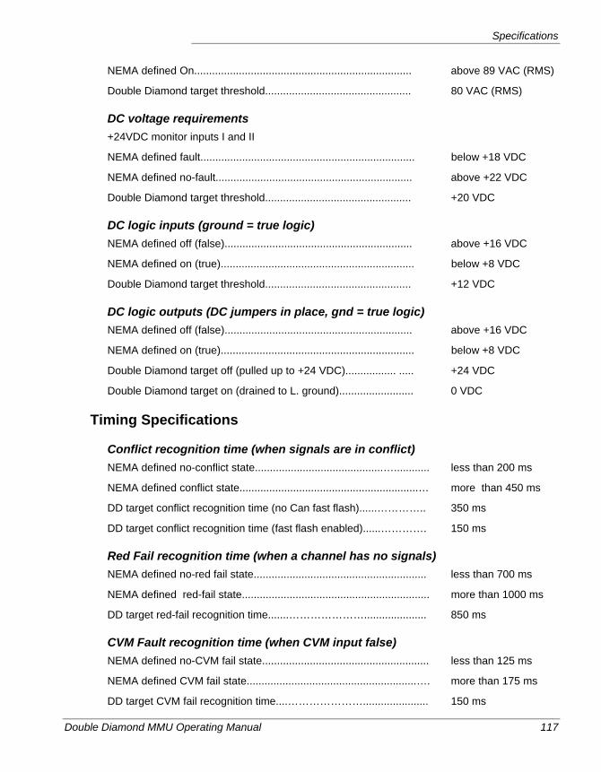
Specifications
Double Diamond MMU Operating Manual 117
NEMA defined On......................................................................... above 89 VAC (RMS)
Double Diamond target threshold................................................. 80 VAC (RMS)
DC voltage requirements +24VDC monitor inputs I and II
NEMA defined fault........................................................................ below +18 VDC
NEMA defined no-fault.................................................................. above +22 VDC
Double Diamond target threshold................................................. +20 VDC
DC logic inputs (ground = true logic) NEMA defined off (false)............................................................... above +16 VDC
NEMA defined on (true)................................................................. below +8 VDC
Double Diamond target threshold................................................. +12 VDC
DC logic outputs (DC jumpers in place, gnd = true logic) NEMA defined off (false)............................................................... above +16 VDC
NEMA defined on (true)................................................................. below +8 VDC
Double Diamond target off (pulled up to +24 VDC)................. ..... +24 VDC
Double Diamond target on (drained to L. ground)......................... 0 VDC
Timing Specifications
Conflict recognition time (when signals are in conflict) NEMA defined no-conflict state...........................................…............ less than 200 ms
NEMA defined conflict state............................................................… more than 450 ms
DD target conflict recognition time (no Can fast flash)......………….. 350 ms
DD target conflict recognition time (fast flash enabled)......…………. 150 ms
Red Fail recognition time (when a channel has no signals) NEMA defined no-red fail state.......................................................... less than 700 ms
NEMA defined red-fail state............................................................... more than 1000 ms
DD target red-fail recognition time.......…………………..................... 850 ms
CVM Fault recognition time (when CVM input false) NEMA defined no-CVM fail state........................................................ less than 125 ms
NEMA defined CVM fail state.........................................................…. more than 175 ms
DD target CVM fail recognition time....…………………...................... 150 ms
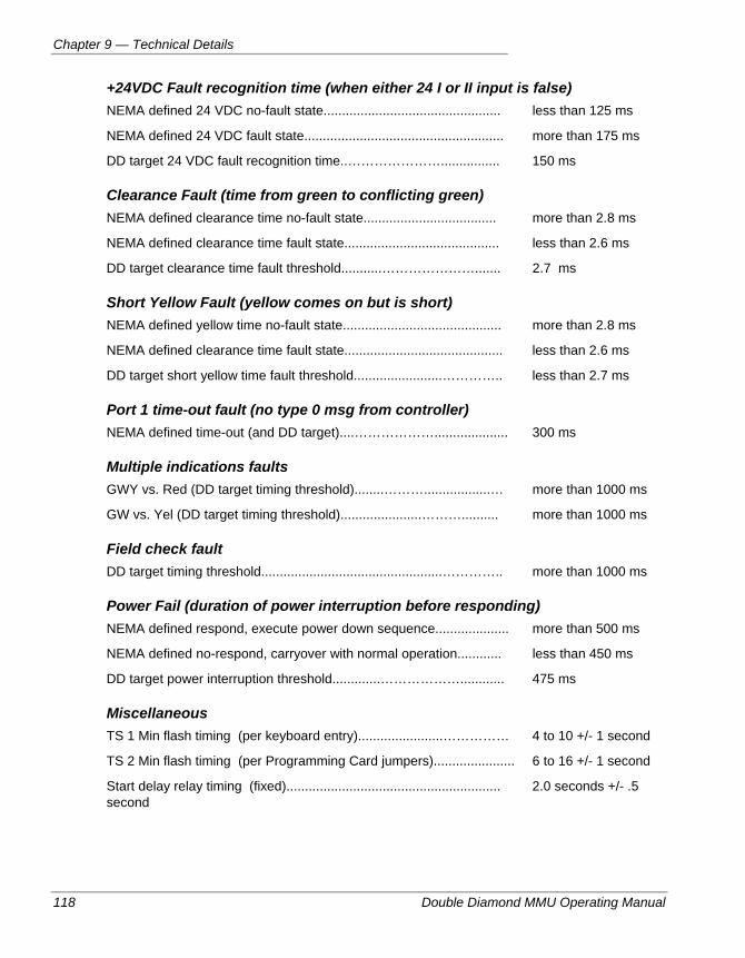
Chapter 9 — Technical Details
118 Double Diamond MMU Operating Manual
+24VDC Fault recognition time (when either 24 I or II input is false) NEMA defined 24 VDC no-fault state................................................ less than 125 ms
NEMA defined 24 VDC fault state...................................................... more than 175 ms
DD target 24 VDC fault recognition time..…………………................ 150 ms
Clearance Fault (time from green to conflicting green) NEMA defined clearance time no-fault state.................................... more than 2.8 ms
NEMA defined clearance time fault state.......................................... less than 2.6 ms
DD target clearance time fault threshold...........…………………....... 2.7 ms
Short Yellow Fault (yellow comes on but is short) NEMA defined yellow time no-fault state........................................... more than 2.8 ms
NEMA defined clearance time fault state........................................... less than 2.6 ms
DD target short yellow time fault threshold........................………….. less than 2.7 ms
Port 1 time-out fault (no type 0 msg from controller) NEMA defined time-out (and DD target)....……………….................... 300 ms
Multiple indications faults GWY vs. Red (DD target timing threshold)........………..................… more than 1000 ms
GW vs. Yel (DD target timing threshold)......................……….......... more than 1000 ms
Field check fault DD target timing threshold.................................................………….. more than 1000 ms
Power Fail (duration of power interruption before responding) NEMA defined respond, execute power down sequence.................... more than 500 ms
NEMA defined no-respond, carryover with normal operation............ less than 450 ms
DD target power interruption threshold.............………………............ 475 ms
Miscellaneous TS 1 Min flash timing (per keyboard entry).......................…………… 4 to 10 +/- 1 second
TS 2 Min flash timing (per Programming Card jumpers)...................... 6 to 16 +/- 1 second
Start delay relay timing (fixed).......................................................... 2.0 seconds +/- .5 second
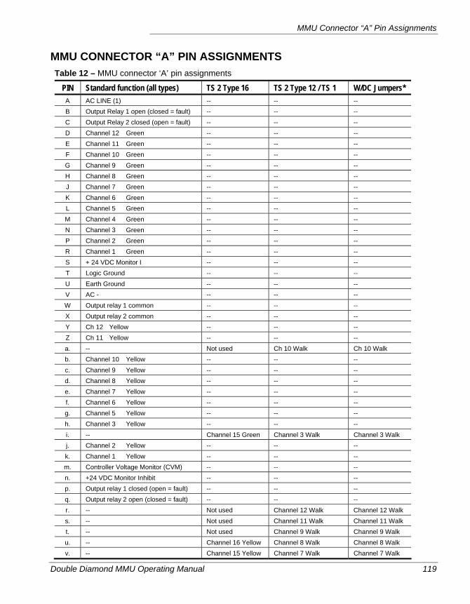
MMU Connector “A” Pin Assignments
Double Diamond MMU Operating Manual 119
MMU CONNECTOR “A” PIN ASSIGNMENTS Table 12 – MMU connector ‘A’ pin assignments
PIN Standard function (all types) TS 2 Type 16 TS 2 Type 12 / TS 1 W/DC Jumpers* A AC LINE (1) -- -- -- B Output Relay 1 open (closed = fault) -- -- -- C Output Relay 2 closed (open = fault) -- -- -- D Channel 12 Green -- -- -- E Channel 11 Green -- -- -- F Channel 10 Green -- -- -- G Channel 9 Green -- -- -- H Channel 8 Green -- -- -- J Channel 7 Green -- -- -- K Channel 6 Green -- -- -- L Channel 5 Green -- -- -- M Channel 4 Green -- -- -- N Channel 3 Green -- -- -- P Channel 2 Green -- -- -- R Channel 1 Green -- -- -- S + 24 VDC Monitor I -- -- -- T Logic Ground -- -- -- U Earth Ground -- -- -- V AC - -- -- -- W Output relay 1 common -- -- -- X Output relay 2 common -- -- -- Y Ch 12 Yellow -- -- -- Z Ch 11 Yellow -- -- -- a. -- Not used Ch 10 Walk Ch 10 Walk b. Channel 10 Yellow -- -- -- c. Channel 9 Yellow -- -- -- d. Channel 8 Yellow -- -- -- e. Channel 7 Yellow -- -- -- f. Channel 6 Yellow -- -- -- g. Channel 5 Yellow -- -- -- h. Channel 3 Yellow -- -- -- i. -- Channel 15 Green Channel 3 Walk Channel 3 Walk j. Channel 2 Yellow -- -- -- k. Channel 1 Yellow -- -- -- m. Controller Voltage Monitor (CVM) -- -- -- n. +24 VDC Monitor Inhibit -- -- -- p. Output relay 1 closed (open = fault) -- -- -- q. Output relay 2 open (closed = fault) -- -- -- r. -- Not used Channel 12 Walk Channel 12 Walk s. -- Not used Channel 11 Walk Channel 11 Walk t. -- Not used Channel 9 Walk Channel 9 Walk u. -- Channel 16 Yellow Channel 8 Walk Channel 8 Walk v. -- Channel 15 Yellow Channel 7 Walk Channel 7 Walk
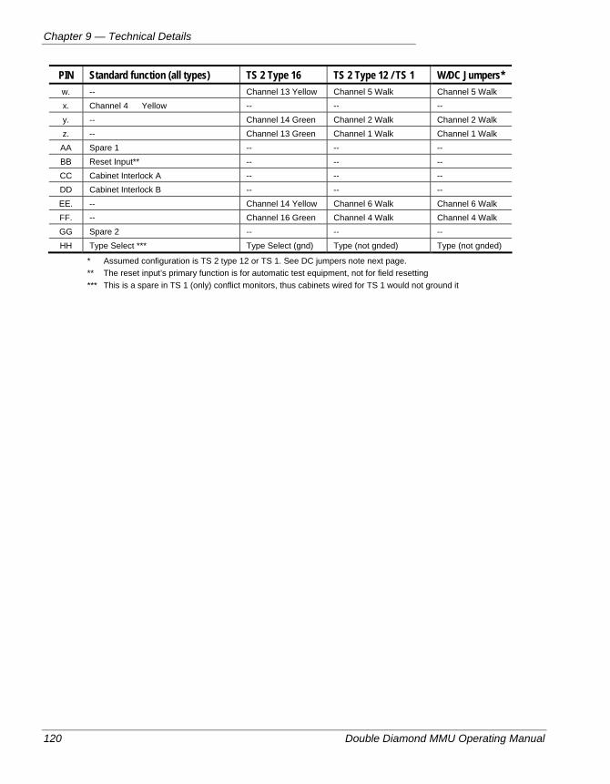
Chapter 9 — Technical Details
120 Double Diamond MMU Operating Manual
PIN Standard function (all types) TS 2 Type 16 TS 2 Type 12 / TS 1 W/DC Jumpers* w. -- Channel 13 Yellow Channel 5 Walk Channel 5 Walk x. Channel 4 Yellow -- -- -- y. -- Channel 14 Green Channel 2 Walk Channel 2 Walk z. -- Channel 13 Green Channel 1 Walk Channel 1 Walk AA Spare 1 -- -- -- BB Reset Input** -- -- -- CC Cabinet Interlock A -- -- -- DD Cabinet Interlock B -- -- -- EE. -- Channel 14 Yellow Channel 6 Walk Channel 6 Walk FF. -- Channel 16 Green Channel 4 Walk Channel 4 Walk GG Spare 2 -- -- -- HH Type Select *** Type Select (gnd) Type (not gnded) Type (not gnded)
* Assumed configuration is TS 2 type 12 or TS 1. See DC jumpers note next page. ** The reset input’s primary function is for automatic test equipment, not for field resetting *** This is a spare in TS 1 (only) conflict monitors, thus cabinets wired for TS 1 would not ground it
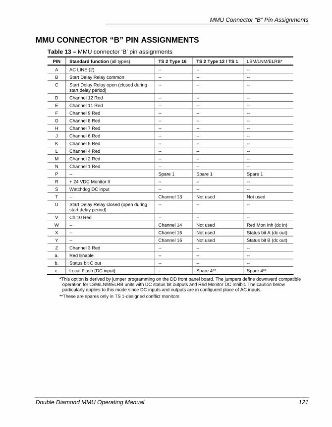
MMU Connector “B” Pin Assignments
Double Diamond MMU Operating Manual 121
MMU CONNECTOR “B” PIN ASSIGNMENTS Table 13 – MMU connector ‘B’ pin assignments
PIN Standard function (all types) TS 2 Type 16 TS 2 Type 12 / TS 1 LSM/LNM/ELRB*
A AC LINE (2) -- -- -- B Start Delay Relay common -- -- -- C Start Delay Relay open (closed during
start delay period) -- -- --
D Channel 12 Red -- -- -- E Channel 11 Red -- -- -- F Channel 9 Red -- -- -- G Channel 8 Red -- -- -- H Channel 7 Red -- -- -- J Channel 6 Red -- -- -- K Channel 5 Red -- -- -- L Channel 4 Red -- -- -- M Channel 2 Red -- -- -- N Channel 1 Red -- -- -- P -- Spare 1 Spare 1 Spare 1 R + 24 VDC Monitor II -- -- -- S Watchdog DC input -- -- -- T -- Channel 13 Not used Not used U Start Delay Relay closed (open during
start delay period) -- -- --
V Ch 10 Red -- -- -- W -- Channel 14 Not used Red Mon Inh (dc in) X -- Channel 15 Not used Status bit A (dc out) Y -- Channel 16 Not used Status bit B (dc out) Z Channel 3 Red -- -- -- a. Red Enable -- -- -- b. Status bit C out -- -- -- c. Local Flash (DC input) -- Spare 4** Spare 4**
*This option is derived by jumper programming on the DD front panel board. The jumpers define downward compatible operation for LSM/LNM/ELRB units with DC status bit outputs and Red Monitor DC Inhibit. The caution below particularly applies to this mode since DC inputs and outputs are in configured place of AC inputs.
**These are spares only in TS 1-designed conflict monitors
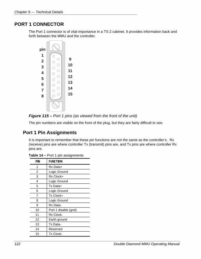
Chapter 9 — Technical Details
122 Double Diamond MMU Operating Manual
PORT 1 CONNECTOR The Port 1 connector is of vital importance in a TS 2 cabinet. It provides information back and forth between the MMU and the controller.
pin 1
9 2 10 3 11 4 12 5 13 6 14 7 15 8
Figure 115 – Port 1 pins (as viewed from the front of the unit)
The pin numbers are visible on the front of the plug, but they are fairly difficult to see.
Port 1 Pin Assignments It is important to remember that these pin functions are not the same as the controller’s. Rx (receive) pins are where controller Tx (transmit) pins are, and Tx pins are where controller Rx pins are.
Table 14 – Port 1 pin assignments PIN FUNCTION 1 Rx Data+ 2 Logic Ground 3 Rx Clock+ 4 Logic Ground 5 Tx Data+ 6 Logic Ground 7 Tx Clock+ 8 Logic Ground 9 Rx Data-
10 Port 1 disable (gnd) 11 Rx Clock- 12 Earth ground 13 Tx Data- 14 Reserved 15 Tx Clock-
Port 1 Connector
Double Diamond MMU Operating Manual 123
Disabling Port 1 Port 1 can be defeated in type 16 mode* by creating a port 1 shunting plug that jumpers pin 10 to any of the Logic ground pins. Note that this will defeat port 1 only as far as the MMU is concerned. If the controller is a TS 2 unit, it must be programmed to defeat port 1 as well (check the controller manual’s port 1 options programming).
Note Port 1 is automatically defeated in TS 2 type 12 and TS 1 modes.
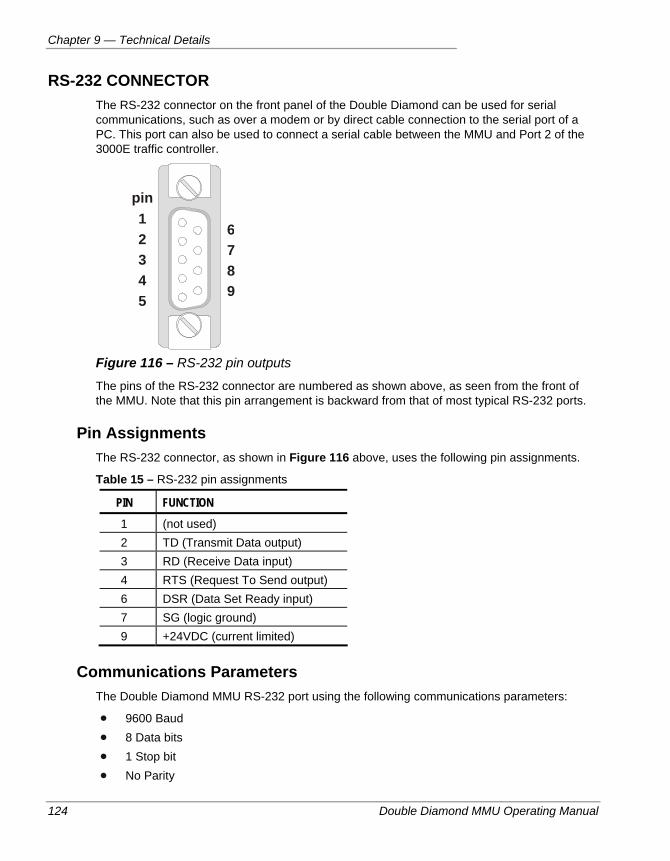
Chapter 9 — Technical Details
124 Double Diamond MMU Operating Manual
RS-232 CONNECTOR The RS-232 connector on the front panel of the Double Diamond can be used for serial communications, such as over a modem or by direct cable connection to the serial port of a PC. This port can also be used to connect a serial cable between the MMU and Port 2 of the 3000E traffic controller.
pin 1 2 3 4 5
6789
Figure 116 – RS-232 pin outputs
The pins of the RS-232 connector are numbered as shown above, as seen from the front of the MMU. Note that this pin arrangement is backward from that of most typical RS-232 ports.
Pin Assignments The RS-232 connector, as shown in Figure 116 above, uses the following pin assignments.
Table 15 – RS-232 pin assignments
PIN FUNCTION 1 (not used) 2 TD (Transmit Data output) 3 RD (Receive Data input) 4 RTS (Request To Send output) 6 DSR (Data Set Ready input) 7 SG (logic ground) 9 +24VDC (current limited)
Communications Parameters The Double Diamond MMU RS-232 port using the following communications parameters:
9600 Baud 8 Data bits 1 Stop bit No Parity
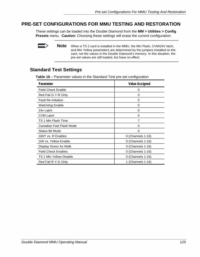
Pre-set Configurations For MMU Testing And Restoration
Double Diamond MMU Operating Manual 125
PRE-SET CONFIGURATIONS FOR MMU TESTING AND RESTORATION These settings can be loaded into the Double Diamond from the MM > Utilities > Config Presets menu. Caution: Choosing these settings will erase the current configuration.
Note When a TS 2 card is installed in the MMU, the Min Flash, CVM/24V latch, and Min Yellow parameters are determined by the jumpers installed on the card, not the values in the Double Diamond’s memory. In this situation, the pre-set values are still loaded, but have no effect.
Standard Test Settings Table 16 – Parameter values in the Standard Test pre-set configuration
Parameter Value Assigned Field Check Enable 0 Red Fail G-Y-R Only 0 Fault Re-Initialize 0 Watchdog Enable 0 24v Latch 0 CVM Latch 0 TS 1 Min Flash Time 7 Canadian Fast Flash Mode 0 Status Bit Mode 0 GWY vs. R Enables 0 (Channels 1-16) GW vs. Yellow Enable 0 (Channels 1-16) Display Green As Walk 0 (Channels 1-16) Field Check Enables 0 (Channels 1-16) TS 1 Min Yellow Disable 0 (Channels 1-16) Red Fail R-Y-G Only 1 (Channels 1-16)
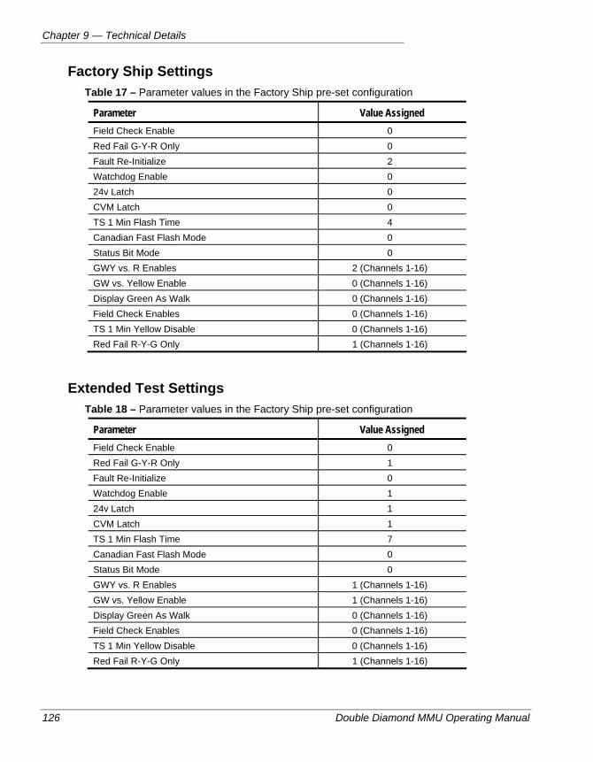
Chapter 9 — Technical Details
126 Double Diamond MMU Operating Manual
Factory Ship Settings Table 17 – Parameter values in the Factory Ship pre-set configuration
Parameter Value Assigned Field Check Enable 0 Red Fail G-Y-R Only 0 Fault Re-Initialize 2 Watchdog Enable 0 24v Latch 0 CVM Latch 0 TS 1 Min Flash Time 4 Canadian Fast Flash Mode 0 Status Bit Mode 0 GWY vs. R Enables 2 (Channels 1-16) GW vs. Yellow Enable 0 (Channels 1-16) Display Green As Walk 0 (Channels 1-16) Field Check Enables 0 (Channels 1-16) TS 1 Min Yellow Disable 0 (Channels 1-16) Red Fail R-Y-G Only 1 (Channels 1-16)
Extended Test Settings Table 18 – Parameter values in the Factory Ship pre-set configuration
Parameter Value Assigned Field Check Enable 0 Red Fail G-Y-R Only 1 Fault Re-Initialize 0 Watchdog Enable 1 24v Latch 1 CVM Latch 1 TS 1 Min Flash Time 7 Canadian Fast Flash Mode 0 Status Bit Mode 0 GWY vs. R Enables 1 (Channels 1-16) GW vs. Yellow Enable 1 (Channels 1-16) Display Green As Walk 0 (Channels 1-16) Field Check Enables 0 (Channels 1-16) TS 1 Min Yellow Disable 0 (Channels 1-16) Red Fail R-Y-G Only 1 (Channels 1-16)

Pre-set Configurations For MMU Testing And Restoration
Double Diamond MMU Operating Manual 127
Use Of The Config Pre-Sets With Automatic Monitor Testers The Config Presets have been provided for setting factory ship defaults and for use with Automatic monitor testers. In the latter case, certain monitoring features can be turned on or off depending on the tests applied.
To use the Config Presets 1. If the unit is from the field and is to be returned to the field, copy the existing config set-
up values on the chart on page 129. These should be restored after testing.
2. Prior to running the tester in the “Standard Test” mode, go to the Utilities menu, Config Presets and load the Standard test config. Run the standard test.
3. After completion of the standard test, the test unit should stop and prompt for the extended test set-up. Go back to the Utilities menu, Config Presets and load the Extended test config. Run the extended test.
4. Prior to installing the unit in the field, re-configure to the state prior to testing. Use factory ship if no specific extended features are required.
5. If the controller is configured to use Canadian fast-flash timings, it should be turned-off if you are using the Config Presets in the MMU.
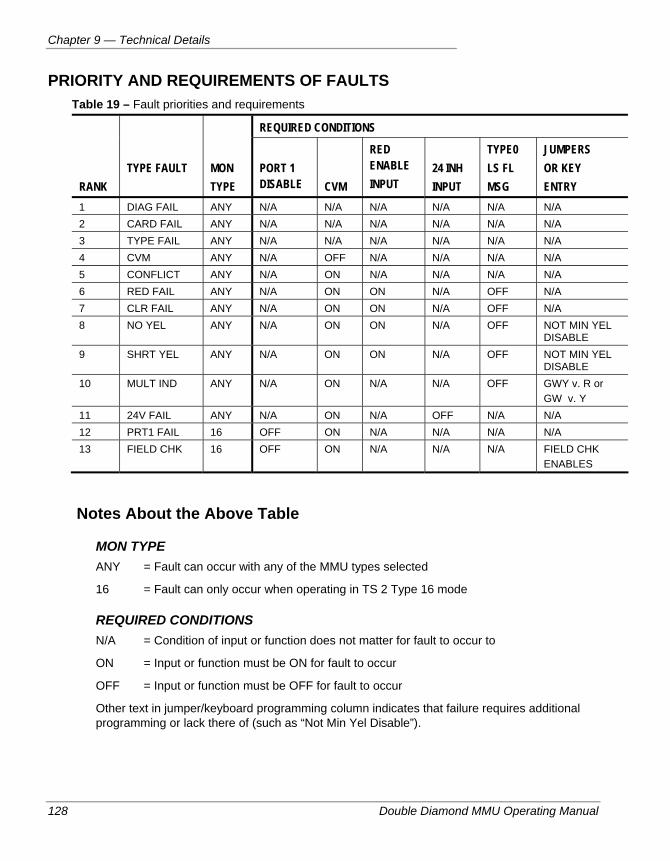
Chapter 9 — Technical Details
128 Double Diamond MMU Operating Manual
PRIORITY AND REQUIREMENTS OF FAULTS Table 19 – Fault priorities and requirements
REQUIRED CONDITIONS
RANK
TYPE FAULT
MON TYPE
PORT 1 DISABLE
CVM
RED ENABLE INPUT
24 INH INPUT
TYPE0 LS FL MSG
JUMPERS OR KEY ENTRY
1 DIAG FAIL ANY N/A N/A N/A N/A N/A N/A 2 CARD FAIL ANY N/A N/A N/A N/A N/A N/A 3 TYPE FAIL ANY N/A N/A N/A N/A N/A N/A 4 CVM ANY N/A OFF N/A N/A N/A N/A 5 CONFLICT ANY N/A ON N/A N/A N/A N/A 6 RED FAIL ANY N/A ON ON N/A OFF N/A 7 CLR FAIL ANY N/A ON ON N/A OFF N/A 8 NO YEL ANY N/A ON ON N/A OFF NOT MIN YEL
DISABLE 9 SHRT YEL ANY N/A ON ON N/A OFF NOT MIN YEL
DISABLE 10 MULT IND ANY N/A ON N/A N/A OFF GWY v. R or
GW v. Y 11 24V FAIL ANY N/A ON N/A OFF N/A N/A 12 PRT1 FAIL 16 OFF ON N/A N/A N/A N/A 13 FIELD CHK 16 OFF ON N/A N/A N/A FIELD CHK
ENABLES
Notes About the Above Table
MON TYPE ANY = Fault can occur with any of the MMU types selected
16 = Fault can only occur when operating in TS 2 Type 16 mode
REQUIRED CONDITIONS N/A = Condition of input or function does not matter for fault to occur to
ON = Input or function must be ON for fault to occur
OFF = Input or function must be OFF for fault to occur
Other text in jumper/keyboard programming column indicates that failure requires additional programming or lack there of (such as “Not Min Yel Disable”).
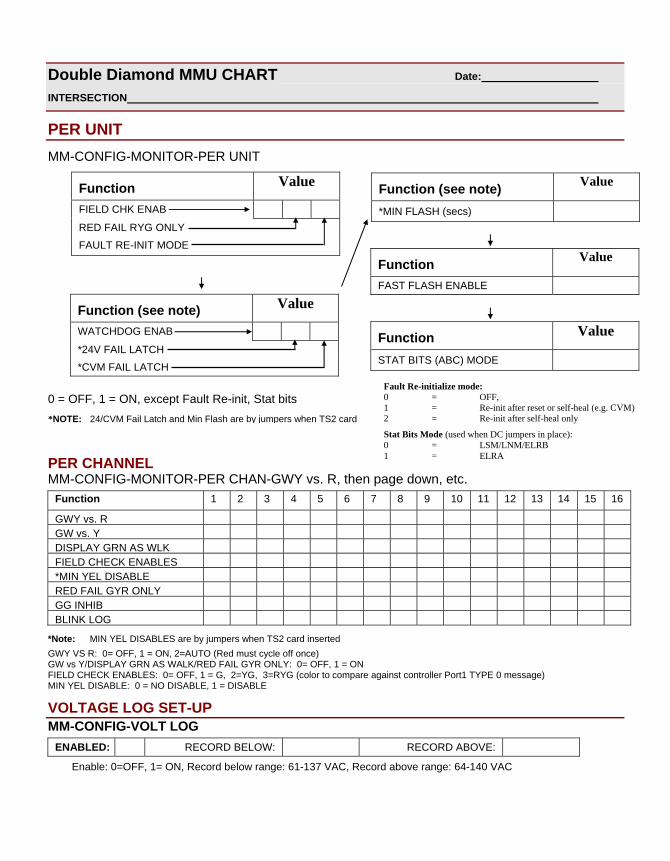
Double Diamond MMU CHART Date: INTERSECTION
PER UNIT MM-CONFIG-MONITOR-PER UNIT
0 = OFF, 1 = ON, except Fault Re-init, Stat bits
PER CHANNEL MM-CONFIG-MONITOR-PER CHAN-GWY vs. R, then page down, etc.
Function 1 2 3 4 5 6 7 8 9 10 11 12 13 14 15 16
GWY vs. R GW vs. Y DISPLAY GRN AS WLK FIELD CHECK ENABLES *MIN YEL DISABLE RED FAIL GYR ONLY GG INHIB BLINK LOG
*Note: MIN YEL DISABLES are by jumpers when TS2 card inserted GWY VS R: 0= OFF, 1 = ON, 2=AUTO (Red must cycle off once) GW vs Y/DISPLAY GRN AS WALK/RED FAIL GYR ONLY: 0= OFF, 1 = ON FIELD CHECK ENABLES: 0= OFF, 1 = G, 2=YG, 3=RYG (color to compare against controller Port1 TYPE 0 message) MIN YEL DISABLE: 0 = NO DISABLE, 1 = DISABLE
VOLTAGE LOG SET-UP MM-CONFIG-VOLT LOG
ENABLED: RECORD BELOW: RECORD ABOVE:
Enable: 0=OFF, 1= ON, Record below range: 61-137 VAC, Record above range: 64-140 VAC
*NOTE: 24/CVM Fail Latch and Min Flash are by jumpers when TS2 card
Function Value
FIELD CHK ENAB
RED FAIL RYG ONLY FAULT RE-INIT MODE
Function (see note) Value
*MIN FLASH (secs)
Function Value
FAST FLASH ENABLE
Function Value
STAT BITS (ABC) MODE
Function (see note) Value
WATCHDOG ENAB *24V FAIL LATCH *CVM FAIL LATCH
Fault Re-initialize mode: 0 = OFF, 1 = Re-init after reset or self-heal (e.g. CVM) 2 = Re-init after self-heal only
Stat Bits Mode (used when DC jumpers in place): 0 = LSM/LNM/ELRB 1 = ELRA
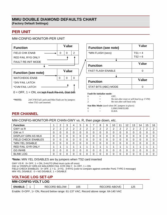
MMU DOUBLE DIAMOND DEFAULTS CHART (Factory Default Settings)
PER UNIT MM-CONFIG-MONITOR-PER UNIT
0 = OFF, 1 = ON, except Fault Re-init, Stat bits
PER CHANNEL
MM-CONFIG-MONITOR-PER CHAN-GWY vs. R, then page down, etc. Function 1 2 3 4 5 6 7 8 9 10 11 12 13 14 15 16 GWY vs R 2 2 2 2 2 2 2 2 2 2 2 2 2 2 2 2 GW vs Y 0 0 0 0 0 0 0 0 0 0 0 0 0 0 0 0 DISPLAY GRN AS WLK 0 0 0 0 0 0 0 0 0 0 0 0 0 0 0 0 FIELD CHECK ENABLES 0 0 0 0 0 0 0 0 0 0 0 0 0 0 0 0 *MIN YEL DISABLE 0 0 0 0 0 0 0 0 0 0 0 0 0 0 0 0 RED FAIL GYR ONLY 1 1 1 1 1 1 1 1 1 1 1 1 1 1 1 1 GG INHIB 0 0 0 0 0 0 0 0 0 0 0 0 0 0 0 0 BLINK LOG 0 0 0 0 0 0 0 0 0 0 0 0 0 0 0 0
*Note: MIN YEL DISABLES are by jumpers when TS2 card inserted GWY VS R: 0= OFF, 1 = ON, 2=AUTO (Red must cycle off once) GW vs Y/DISPLAY GRN AS WALK/RED FAIL GYR ONLY: 0= OFF, 1 = ON FIELD CHECK ENABLES: 0= OFF, 1 = G, 2=YG, 3=RYG (color to compare against controller Port1 TYPE 0 message) MIN YEL DISABLE: 0 = NO DISABLE, 1 = DISABLE
VOLTAGE LOG SET-UP MM-CONFIG-VOLT LOG
ENABLE: 1 RECORD BELOW: 105 RECORD ABOVE: 125
Enable: 0=OFF, 1= ON, Record below range: 61-137 VAC, Record above range: 64-140 VAC
*NOTE: 24/CVM Fail Latch and Min Flash are by jumpers when TS2 card inserted.
Function Value
FIELD CHK ENAB 0 0 2
RED FAIL RYG ONLY FAULT RE-INIT MODE
Function (see note) Value
*MIN FLASH (secs) TS1 = 4 TS2 = 6
Function Value
FAST FLASH ENABLE 0
Function Value
STAT BITS (ABC) MODE 0
Function (see note) Value
WATCHDOG ENAB 0 0 0
*24V FAIL LATCH *CVM FAIL LATCH
Fault Re-initialize mode: 0 = OFF, 1 = Re-init after reset or self-heal (e.g. CVM) 2 = Re-init after self-heal only
Stat Bits Mode (used when DC jumpers in place): 0 = LSM/LNM/ELRB 1 = ELRA
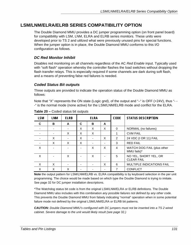
LSM/LNM/ELRA/ELRB Series Compatibility Option
Tables and Pin Listings 131
LSM/LNM/ELRA/ELRB SERIES COMPATIBILITY OPTION The Double Diamond MMU provides a DC jumper programming option (on front panel board) for compatibility with LSM, LNM, ELRA and ELRB series monitors. These units were developed prior to TS 2 and utilized what were previously unused pins for special functions. When the jumper option is in place, the Double Diamond MMU conforms to this I/O configuration as follows.
DC Red Monitor Inhibit Disables red monitoring on all channels regardless of the AC Red Enable input. Typically used with “soft flash” operation whereby the controller flashes the load switches without dropping the flash transfer relays. This is especially required if some channels are dark during soft flash, and a means of preventing false red failures is needed.
Coded Status Bit outputs Three outputs are provided to indicate the operation status of the Double Diamond MMU as follows:
Note that “X” represents the ON state (Logic gnd), of the output and “–“ is OFF (+24V), thus “- - -“ is the normal mode (none active) for the LSM/LNM/ELRB mode and conflict for the ELRA.
Table 20 – Coded status bit outputs
LSM LNM ELRB ELRA C B A C B A
CODE STATUS DESCRIPTION
- - - X X X 0 NORMAL (no failures) - - X X X 1 CVM FAIL - X - X - X 2 24 VDC (I OR 11) FAIL - X X X - - 3 RED FAIL X - - - X X 4 WATCH DOG FAIL (plus other
MMU fails)* X - X - X - 5 NO YEL, SHORT YEL, OR
CLEAR FAIL X X - - - X 6 MULTIPLE INDICATIONS FAIL X X X - - - 7 CONFLICT
Note the output pattern for LSM/LNM/ELRB vs. ELRA compatibility is by keyboard selection in the per unit programming. The choice would be made based on which type the Double Diamond is trying to imitate. See page 32 for DC jumper installation descriptions.
*The Watchdog status bit code is from the original LSM/LNM/ELRA or ELRB definitions. The Double Diamond MMU also includes with this combination any possible failures not defined by any other code. This prevents the Double Diamond MMU from falsely indicating “normal” operation when in some potential failure mode not defined by the original LSM/LNM/ELRA or ELRB bit patterns.
CAUTION: Double Diamond MMU’s configured with DC jumpers must not be inserted into a TS 2 wired cabinet. Severe damage to the unit would likely result (see page 32.)

Chapter 9 — Technical Details
132 Double Diamond MMU Operating Manual
Double Diamond MMU Operating Manual 133
Glossary
3000 Series — A line of traffic controller hardware produced by Peek Traffic, Inc.
AC — Alternating Current
Barrier — A logical term to describe a line of compatibility in a multi-ring signal plan in which all rings are interlocked. Barriers assure that there will be no concurrent selection and timing of conflicting phases for traffic phases on different rings.
BIU — Bus Interface Unit, required to interface a TS 2, Type 1 controller to any type of cabinet hardware.
CA — Controller Assembly
Cabinet — An outdoor enclosure for housing controller units, master units, detector electronics and other associated equipment.
CLMATS — A software package created and maintained by Peek Traffic Systems that allows traffic management personnel to interact with and control a variety of Master and Controller hardware. Stands for Closed Loop Multi-Arterial Traffic Control System.
CLR — Phase Clearance. Includes Ped Clearance times for CNA phases.
CMU — Conflict Monitoring Unit. The TS 1 standard’s version of the malfunction management unit. Unlike the MMU, the CMU has no direct interaction with the intersection’s controller.
CNA — Call to Non-Actuated. Provides a method of phase timing where vehicle and pedestrian detectors are not required to serve the associated phases, with operation as defined by NEMA.
Coordination — The state where two or more intersections are configured to communicate with each other in order to time their signals in some manner that improves the greater system performance, rather than being timed independently at each intersection.
CRC — Cyclical Redundancy Check
DCMATS — The software predecessor to CL-MATS, originally only communicated with single controllers
Glossary
134 Double Diamond MMU Operating Manual
DLL — dynamically linked libraries, in the Windows environment, programs store data, graphics and other resources in these linked libraries. CL-MATS uses a number of them.
EEPROM — Electronically eraseable/programmable read-only memory, the programmable memory storage area on the LMD-40 and several other traffic control components.
EGB — Extended Green Band
EP — End of Permissive
EPP — End of Pedestrian Permissive
FO — Force-Off
FOM — Fiber Optic Modem, a device that modulates a signal appropriately for transmission over fiber optic cables
FSK — Frequency shift key
Greenband Analysis — a method of analyzing the amount of green light time available in a set of coordinated traffic intersections.
HDLC — High-level data link control, a Port 1 protocol for TS 2 standard MMU units
Hz — Hertz, a unit of frequency indicating cycles per second
INIT — Initial or Initialization
Intersection — a Controller assigned to a location
Interval — A unit of time that is assigned a certain of controller behavior and signal output in a time-based (non-NEMA) controller.
ITS — Intelligent traffic systems
Local — Connection to a Controller unit
M3000 — The model number of a master unit manufactured by Peek Traffic. Often used in conjunction with Peeks’ Series 3000 and Series 3000E Traffic Controllers
MCE — Manual Control Enable
MMU — Malfunction Management Unit. A TS 2 equipment standard that functions as a sequel to the TS 1 standard’s Conflict Monitor.
MOE — Methods of efficiency
MSCLR — Main Street Clearance
NEMA — National Electrical Manufacturers Association. The industry group that has designed one of a couple of competing standards for intelligent traffic control systems.
PA — Phase Allocation
PE — Preemption
Ped — Pedestrian or Pedestrian phase
PED CLR — Pedestrian Clearance Interval
Glossary
Double Diamond MMU Operating Manual 135
Phase — a single traffic movement. NEMA compatible controllers typically manage the intersection in terms of phases, while earlier controllers use intervals and circuits instead.
PTSI — Peek Traffic Systems Inc.
RAM — Random Access Memory. The main memory of a computer while power is on. Typically does not maintain its memory when power is turned off.
RGB — Reduced Green Band
ROM — Read Only Memory, hard written memory in a computer that is maintained even when power is removed. Typically used to store basic OS code and firmware programs.
RMS Voltage — Root mean squared voltage. A standardized method of quoting the strength of an AC line voltage that is naturally varying in time.
SDLC — A communications protocol from IBM. It stands for Synchronous Data Link Control.
SP — Start Permissive Period
SPL — Split, in a coordinated traffic system, each intersection in an artery must have the same cycle time. So instead of set times for each phase, a coordinated intersection has a split assigned to each phase. A split is a percentage of the total time available in the cycle.
SPP — Start Pedestrian Permissive Period
TCP/IP — The most common pair of protocols used to send data across an Ethernet or the Internet. Each component in such a system is assigned a unique IP address. IP addressing is used by the various components of CLMATS.
T/F — Terminal and Facilities
TOD — Time of Day
WALK — Walk Interval Time
WRM — Walk Rest Modifier

Glossary
136 Double Diamond MMU Operating Manual
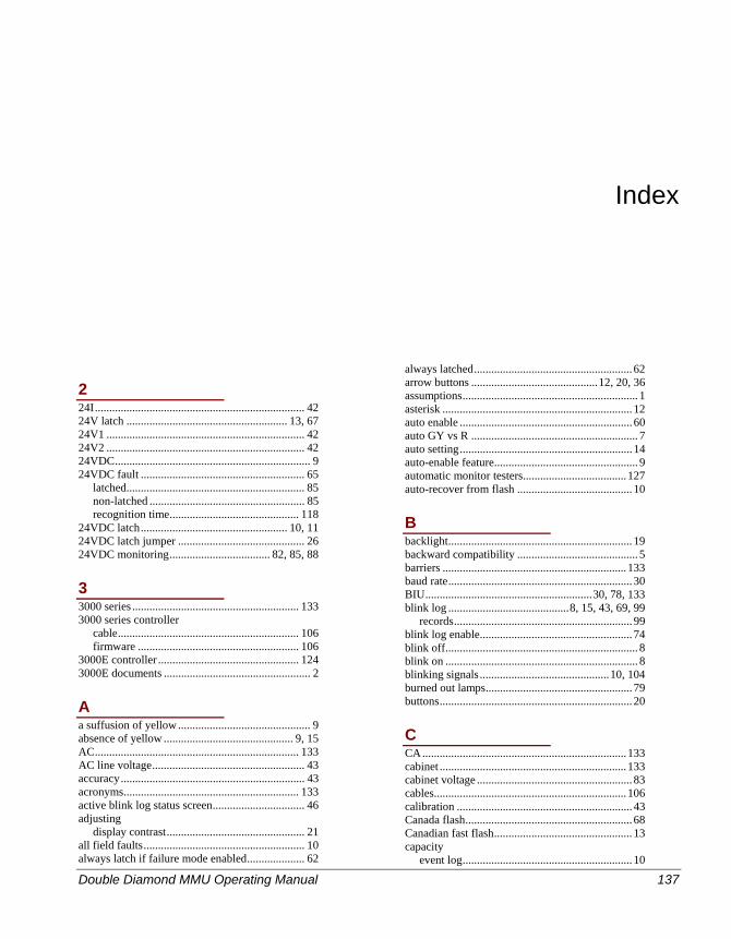
Double Diamond MMU Operating Manual 137
Index
2 24I......................................................................... 42 24V latch ........................................................ 13, 67 24V1 ..................................................................... 42 24V2 ..................................................................... 42 24VDC.................................................................... 9 24VDC fault ......................................................... 65
latched.............................................................. 85 non-latched ...................................................... 85 recognition time............................................. 118
24VDC latch................................................... 10, 11 24VDC latch jumper ............................................ 26 24VDC monitoring................................... 82, 85, 88
3 3000 series .......................................................... 133 3000 series controller
cable............................................................... 106 firmware ........................................................ 106
3000E controller ................................................. 124 3000E documents ................................................... 2
A a suffusion of yellow .............................................. 9 absence of yellow ............................................. 9, 15 AC....................................................................... 133 AC line voltage..................................................... 43 accuracy................................................................ 43 acronyms............................................................. 133 active blink log status screen................................ 46 adjusting
display contrast................................................ 21 all field faults........................................................ 10 always latch if failure mode enabled.................... 62
always latched....................................................... 62 arrow buttons ............................................12, 20, 36 assumptions............................................................. 1 asterisk .................................................................. 12 auto enable ............................................................ 60 auto GY vs R .......................................................... 7 auto setting............................................................ 14 auto-enable feature.................................................. 9 automatic monitor testers....................................127 auto-recover from flash ........................................ 10
B backlight................................................................ 19 backward compatibility .......................................... 5 barriers ................................................................133 baud rate................................................................ 30 BIU..........................................................30, 78, 133 blink log ..........................................8, 15, 43, 69, 99
records.............................................................. 99 blink log enable..................................................... 74 blink off................................................................... 8 blink on ................................................................... 8 blinking signals.............................................10, 104 burned out lamps................................................... 79 buttons................................................................... 20
C CA.......................................................................133 cabinet .................................................................133 cabinet voltage ...................................................... 83 cables...................................................................106 calibration ............................................................. 43 Canada flash.......................................................... 68 Canadian fast flash................................................ 13 capacity
event log........................................................... 10
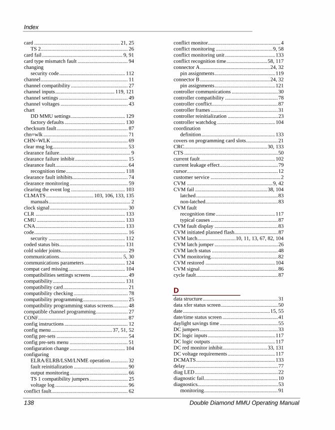
Index
138 Double Diamond MMU Operating Manual
card ................................................................. 21, 25 TS 2.................................................................. 26
card fail ............................................................. 9, 91 card type mismatch fault ...................................... 94 changing
security code.................................................. 112 channel.................................................................. 11 channel compatibility ........................................... 27 channel inputs............................................. 119, 121 channel settings .................................................... 49 channel voltages ................................................... 43 chart
DD MMU settings ......................................... 129 factory defaults .............................................. 130
checksum fault...................................................... 87 chn=wlk ................................................................ 71 CHN=WLK .......................................................... 69 clear msg log......................................................... 53 clearance failure...................................................... 9 clearance failure inhibit ........................................ 15 clearance fault....................................................... 64
recognition time............................................. 118 clearance fault inhibits.......................................... 74 clearance monitoring ............................................ 59 clearing the event log ......................................... 103 CLMATS.................................... 103, 106, 133, 135
manuals.............................................................. 2 clock signal ........................................................... 30 CLR .................................................................... 133 CMU ................................................................... 133 CNA.................................................................... 133 code....................................................................... 16
security .......................................................... 112 coded status bits.................................................. 131 cold solder joints................................................... 29 communications................................................ 5, 30 communications parameters ............................... 124 compat card missing........................................... 104 compatibilities settings screens ............................ 49 compatibility....................................................... 131 compatibility card................................................. 21 compatibility checking ......................................... 78 compatibility programming.................................. 25 compatibility programming status screens........... 48 compatible channel programming........................ 27 CONF.................................................................... 87 config instructions ................................................ 12 config menu .............................................. 37, 51, 52 config pre-sets ...................................................... 54 config pre-sets menu ............................................ 51 configuration change .......................................... 104 configuring
ELRA/ELRB/LSM/LNME operation ............. 32 fault reinitialization ......................................... 90 output monitoring ............................................ 66 TS 1 compatibility jumpers ............................. 25 voltage log ....................................................... 96
conflict fault.......................................................... 62
conflict monitor.......................................................4 conflict monitoring ...........................................9, 58 conflict monitoring unit ......................................133 conflict recognition time...............................58, 117 connector A.....................................................24, 32
pin assignments..............................................119 connector B .....................................................24, 32
pin assignments..............................................121 controller communications ...................................30 controller compatibility ........................................78 controller conflict..................................................87 controller frames ...................................................31 controller reinitialization ......................................23 controller watchdog ............................................104 coordination
definition........................................................133 covers on programming card slots........................21 CRC...............................................................30, 133 CTS .......................................................................50 current fault.........................................................102 current leakage effect............................................79 cursor.....................................................................12 customer service .....................................................2 CVM .................................................................9, 42 CVM fail .......................................................38, 104
latched ..............................................................83 non-latched.......................................................83
CVM fault recognition time .............................................117 typical causes ...................................................87
CVM fault display ................................................83 CVM initiated planned flash.................................87 CVM latch.............................10, 11, 13, 67, 82, 104 CVM latch jumper ................................................26 CVM latch status ..................................................48 CVM monitoring...................................................82 CVM restored .....................................................104 CVM signal...........................................................86 cycle fault..............................................................87
D data structure.........................................................31 data xfer status screen...........................................50 date ..................................................................15, 55 date/time status screen ..........................................41 daylight savings time ............................................55 DC jumpers ...........................................................33 DC logic inputs ...................................................117 DC logic outputs .................................................117 DC red monitor inhibit..................................33, 131 DC voltage requirements ....................................117 DCMATS............................................................133 delay ......................................................................77 diag LED...............................................................22 diagnostic fail........................................................10 diagnostics.............................................................53
monitoring........................................................91
Index
Double Diamond MMU Operating Manual 139
diagnostics fault.................................................... 94 diagnostics monitoring ......................................... 94 dimensions.......................................................... 116 dip histogram.................................................. 45, 97 disabling
blink logs ......................................................... 74 clearance faults ................................................ 74 green to conflicting green................................ 74 min yel clearance............................................. 72 port 1.............................................................. 123 security .......................................................... 113
disp adj button ...................................................... 21 display................................................................... 19
24VDC fault .............................................. 65, 85 active blink log status screen........................... 46 clearance fault.................................................. 64 compatibility programming status .................. 48 conflict fault .................................................... 62 CVM fault........................................................ 83 data xfer status screen ..................................... 50 date/time status ................................................ 41 diagnostics fault............................................... 94 fault detection .................................................. 62 field check fault ............................................... 92 I/O status screen .............................................. 42 min flash .......................................................... 38 min flash and latch enables status ................... 48 min yellow disables status............................... 48 min yellow fault .............................................. 64 multiple indications fault................................. 65 no yellow fault................................................. 63 normal status.................................................... 39 port 1 fault ....................................................... 92 port 1 type 0 message...................................... 41 programming card fault................................... 93 replay screens ................................................ 107 short yellow fault............................................. 64 status ................................................................ 39 type change fault ............................................. 93 voltage log details............................................ 97 voltage log histograms .................................... 45 voltage log status screen.................................. 44 voltage status screens ...................................... 43
display G as W ....................................................... 7 display green as walk ..................................... 14, 71 DLL .................................................................... 134 documentation ........................................................ 2 Double Diamond factory defaults chart ............. 130 Double Diamond front panel................................ 18 Double Diamond settings chart .......................... 129 driver bits.............................................................. 31 dropout threshold................................................ 116 DSP modem manual............................................... 2 DST....................................................................... 55 dual programming cards......................................... 7 dummy load .......................................................... 60
E EEPROM ............................................................134 EGB.....................................................................134 EIA-485 ............................................................5, 30 electrical connections............................................ 75 electrical specs ....................................................116 ELRA mode ............................................................ 5 ELRA/ELRB.................................................69, 131 ELRA/ELRB/LSM/LNME emulation ................. 32
jumpers............................................................. 33 ELRB mode ............................................................ 5 email for tech support ............................................. 2 emulation ............................................................131 enabling
blink log ........................................................... 15 blink logs per channel...................................... 74 fast flash........................................................... 68 field check........................................................ 72 GW vs Y .......................................................... 71 red fail RYG only ............................................ 73 security...........................................................113 voltage log ....................................................... 96
enter button ........................................................... 20 entering
replay mode ..................................................... 21 EP 134 EPP......................................................................134 error checking ....................................................... 30 Ethernet ...............................................................135 event log..........................................................8, 100
capacity ............................................................ 10 clearing...........................................................103 detailed information.......................................101 interface .........................................................100 types of events ...............................................104 viewing...........................................................100
event types ..........................................................104 exiting flash........................................................... 56 ext start.................................................................. 86 extended test ......................................................... 54 extended test settings ..........................................126
F factory ship ........................................................... 54 factory ship settings ............................................126 factory time set ...................................................104 false TS 1 jumpers ..............................................104 false TS 2 jumpers ..............................................104 fast flash enable .................................................... 68 fast flash mode...................................................... 13 fault
24VDC............................................................. 65 24VDC I and II ................................................ 85 cabinet voltage monitoring .............................. 83 card type mismatch.......................................... 94 clearance .......................................................... 64 conflict ............................................................. 62
Index
140 Double Diamond MMU Operating Manual
field check ....................................................... 92 latched info in event log ................................ 102 latches .............................................................. 62 min yellow....................................................... 64 multiple indications ......................................... 65 no yellow ......................................................... 63 port 1................................................................ 92 priorities......................................................... 128 programming card ........................................... 93 red fail.............................................................. 63 requirements .................................................. 128 short yellow ..................................................... 64 showing status during active fault................... 63 type change...................................................... 93
fault detection displays......................................... 62 fault displays......................................................... 39 fault LED .............................................................. 22 fault recovery........................................................ 56 fault reinitialization ........................................ 23, 90 fault reinitialize............................................... 10, 13 fault reinitialize mode........................................... 66 fault state............................................................... 52 fax number.............................................................. 2 field check ............................................................ 66
timing threshold............................................. 118 field check
monitoring ....................................................... 91 field check enable ................................................. 12 field check enables ......................................... 14, 72 field check fault .................................................... 92 field check monitoring.......................................... 67 field chk ................................................................ 69 field fault................................................................. 9 field input channels .............................................. 75 firmware
3000 series controller .................................... 106 LMD-9200 controller .................................... 106
firmware copyright ............................................... 55 flash
exit procedure .................................................. 56 planned ............................................................ 87
flash bit ..................................................... 31, 72, 91 flash request.......................................................... 61 flash time,minimum.............................................. 11 flash timing......................................................... 118 FO ....................................................................... 134 FOM.................................................................... 134 forgotten security code ....................................... 112 frame types ........................................................... 31 frames ................................................................... 30 front panel............................................................. 18 FSK..................................................................... 134 fuse........................................................................ 23
G G to conflicting G fail .......................................... 59 GG inhib ............................................................... 74
GG inhibit .................................................15, 59, 69 green as walk ..................................................14, 71 green to conflicting green monitoring ..................15 greenband analysis..............................................134 GW vs Y .........................................................69, 71 GW vs Y enables ..................................................14 GW vs Y monitoring ............................................59 GWY vs R.......................................................69, 79
codes ................................................................69 GWY vs R enables................................................14 GYW vs R monitoring..........................................60
H hardware overview............................................4, 18 HDLC..............................................................4, 134 help button ............................................................20 highest ...................................................................44 histogram...............................................................97 histograms .............................................................45 host ........................................................................50 hours of service.......................................................2 hysterisis .............................................................116 Hz 134
I I/O status screen....................................................42 IDLE .....................................................................50 INIT.....................................................................134 inputs
electrical ...........................................................75 installation notes ...................................................11 installing
compatibility jumpers ......................................27 interface
overview...........................................................36 intermittent signals................................................10 Internet ................................................................135 intersection..........................................................134 interval ................................................................134 ITS.......................................................................134
J jumper
installation........................................................27 jumper settings......................................................49 jumper soldering ...................................................29 jumpers
ELRA/ELRB/LSM/LNME emulation ............33
K keypad ...................................................................20
L latch.................................................................11, 13
Index
Double Diamond MMU Operating Manual 141
CVM................................................................ 82 date/time .......................................................... 41 fault displays.................................................... 62 lathed info in current fault............................. 102
latch only if latch enabled .................................... 62 latched faults......................................................... 39 latched vs non-latched.......................................... 86 latches ................................................................... 75 LCD ...................................................................... 19
backlight .......................................................... 19 leakage current effect ........................................... 79 LED
diag .................................................................. 22 fault.................................................................. 22 local flash ........................................................ 22 P1 RCV............................................................ 22 P1 XMT........................................................... 22 power ............................................................... 22 type 16 ............................................................. 22
LED status indicators ........................................... 22 LFSH .................................................................... 42 license ................................................................... 55 line voltage ................................................... 41, 116 line/redn................................................................ 43 LMD-9200
cable............................................................... 106 firmware ........................................................ 106
LNME mode........................................................... 5 load switch driver bits .......................................... 31 load switch flash bit........................................ 31, 91 load switch packs.................................................. 82 local .................................................................... 134 local flash............................................................ 104 local flash inactive.............................................. 104 local flash LED..................................................... 22 local flash request monitoring.............................. 61 log
blink................................................................. 46 event .................................................................. 8 viewing ............................................................ 52
log clear .............................................................. 104 log retrieval utility ................................................ 24 log upload utility ................................................ 106 logs
blink................................................................. 99 enabling blink logs .......................................... 74 event .............................................................. 100 overview .......................................................... 96 uploading logs to CLMATS.......................... 106
low voltage ............................................................. 8 lower threshold ..................................................... 96 lowest.................................................................... 44 LS flash command................................................ 78 LSM mode .............................................................. 5 LSM/LNM/ELRB ................................................ 69 LSM/LNM/ELRB/ELRA emulation.................... 13 LSM/LNM/ERLA/ERLB................................... 131
M M3000.................................................................134 main menu.......................................................36, 51 malfunction management unit ................................ 4 manual code .......................................................... 70 manual reset .......................................................... 10 manual time set ...................................................104 manuals ................................................................... 2 MCE....................................................................134 memory fault......................................................... 87 menu
config .........................................................37, 52 main ................................................................. 36 monitor............................................................. 66 setup ................................................................. 37 utilities ............................................................. 53
menu button ....................................................20, 36 menu selection memory........................................ 12 menu system ......................................................... 51 menus
status ................................................................ 52 message log.........................................................100 min flash ............................................................... 68 min flash display................................................... 38 min flash period jumpers ...................................... 26 min flash time .................................................13, 38 min flash time status screen.................................. 48 min yel .................................................................. 69 min yellow ............................................................ 59 min yellow clearance disables .............................. 72 min yellow disables
status screen ..................................................... 48 min yellow fault .................................................... 64 min yellow jumpers .............................................. 26 minimum flash time.............................................. 11 minimum off line voltage threshold ...................116 minimum yellow disables..................................... 11 minimum yellow monitoring ................................ 15 mm ..................... 1, 5, 11, 43, 85, 88, 106, 116, 125 MM ....................................................................... 12 MMU................................................................... 134 MMU config menu ............................................... 51 MMU diag fail ....................................................104 MMU power fail .................................................104 MMU power on ..................................................104 MMU power resume...........................................104 MMU reset ..........................................................104 MMU response frames ......................................... 31 modes ................................................................5, 11 MOE....................................................................134 monitor.................................................................... 4 monitor menu........................................................ 66 monitor testers ....................................................127 monitoring
24VDC............................................................. 88 24VDC I and II ..........................................82, 85 cabinet voltage fault......................................... 83 clearance .......................................................... 59
Index
142 Double Diamond MMU Operating Manual
conflict ............................................................. 58 CVM ................................................................ 82 CVM voltage ................................................... 86 diagnostics ................................................. 91, 94 field check ................................................. 91, 92 green to conflicting green................................ 74 GW vs Y .......................................................... 59 GYW vs R ....................................................... 60 local flash request ............................................ 61 min yellow....................................................... 59 multiple indications ......................................... 59 no yellow ......................................................... 59 overview .......................................................... 58 port 1................................................................ 90 port 1 disable input .......................................... 91 power sources .................................................. 82 programming card ..................................... 91, 93 red fail........................................................ 58, 76 type .................................................................. 91 type change...................................................... 93 voltage ............................................................. 82 watchdog.......................................................... 90
monitors .............................................................. 131 MS 3116 16-26S plug........................................... 24 MS 3116 22-55 SZ plug ....................................... 24 MSCLR............................................................... 134 multiple indications ................................................ 9
timing threshold............................................. 118 multiple indications fault...................................... 65 multiple indications monitoring ........................... 59
N navigating
menus............................................................... 36 status screens ................................................... 40
navigation replay ............................................................. 109
navigation instructions ......................................... 12 NEMA .................................................................... 4
definition........................................................ 134 NEMA plus............................................................. 6 NEMA specification............................................. 23 NEMA TS 2........................................................ 116 NEMA TS 2-2003 standard.................................. 23 no yellow ........................................................ 15, 59 no yellow fault ...................................................... 63 normal status display ...................................... 39, 52 normal status screen ............................................. 20
O opening
menus............................................................... 36 ordering
upload utility.................................................. 106 output monitoring ................................................. 58 output relay........................................................... 23
output relay wiring................................................76 over voltage.............................................................8
P P1 LEDs ................................................................22 PA........................................................................134 paging down..........................................................12 part numbers .......................................................106 PC direct-connect cable ......................................106 PC interface.........................................................106 PE 134 peak histogram................................................45, 97 ped.......................................................................134 ped channels..........................................................11 PED CLR ............................................................134 ped jumpers...........................................................29 peds .......................................................................60 Peek Traffic Technical Support ..............................2 per chan config menu............................................51 per channel monitoring .........................................69 per unit monitoring ...............................................66 permanent reset .....................................................23 pgdn button ...........................................................20 pgup button ...........................................................20 phase
definition........................................................135 phone support..........................................................2 physical dimensions............................................116 picture of the unit....................................................4 pin assignments
connector A....................................................119 connector B ....................................................121 port 1 ..............................................................122 RS-232 port....................................................124
planned flash .........................................................87 plug specification..................................................24 port 1 .........................................................11, 23, 30
disable input monitoring..................................91 disabling.........................................................123 interruption.....................................................104 monitoring........................................................90 pin assignments..............................................122 protocol ............................................................30 restored...........................................................104 time set ...........................................................104 type 0 message display ....................................41
port 1 failure..........................................................87 port 1 fault.............................................................92
time-out ..........................................................118 port 1 interface ........................................................5 port 1 status ...........................................................22 port 1 type 0 ....................................................62, 93 power fail
timing threshold .............................................118 power interruptions ...............................................10 power LED............................................................22 power on/off..........................................................10
Index
Double Diamond MMU Operating Manual 143
power source monitoring...................................... 82 power up min flash display .................................. 38 pre-set configurations......................................... 125 priority of faults.................................................. 128 programming
channel compatibility ...................................... 27 programming card ................................................ 25
monitoring ....................................................... 91 TS 1 ................................................................. 21
programming card monitoring ............................. 93 programming card slot ......................................... 21 programming card status screens ......................... 48 PTSI .................................................................... 135 purpose of manual .................................................. 1
Q quick setup
global settings.................................................. 12 per channel settings ......................................... 14
quick setup instructions........................................ 11
R R/C snubbers ........................................................ 79 RAM ................................................................... 135 RCV...................................................................... 50 RD CONFIG......................................................... 50 RD LOG ............................................................... 50 RD TIME.............................................................. 50 RD VOLT............................................................. 50 re fail RYG only ................................................... 10 receive status ........................................................ 22 recognition time.................................................... 58 red 14 .................................................................... 33 red 15 .................................................................... 33 red 16 .................................................................... 33 red enable input ............................................ 58, 116 red enable input control........................................ 76 red enable voltage................................................. 43 red fail............................................................... 9, 79
recognition time....................................... 58, 117 RYG only option ............................................. 58
red fail fault .......................................................... 63 red fail GYR only ................................................. 12 red fail monitoring.......................................... 58, 76 red fail RYG only ............................... 15, 66, 67, 73 red input................................................................ 29 red inputs ............................................................ 116 red signal thresholds............................................. 58 red signal tied high ............................................... 60 reinitialization....................................................... 90 reinitialize fault............................................... 10, 13 reinitialize mode ................................................... 66 related documents................................................... 2 relay wiring........................................................... 76 release notes ........................................................... 2 RELY.................................................................... 42
removing programming card............................................ 21 slot covers ........................................................ 21
replacing the fuse.................................................. 23 replay.........................................................7, 12, 100
controls...........................................................108 replay button .................................................21, 108 replay mode.........................................................107 replay stack .........................................................107 reset ....................................................................... 10 reset button............................................................ 23 resetting................................................................. 56 resetting the unit ................................................... 23 restore threshold..................................................116 revision.................................................................. 55 RGB ....................................................................135 RMI ....................................................................... 42 RMS ..............................................................58, 135 ROM ...................................................................135 RS232 port ..........................................................106 RS-232 port........................................................... 24
status display.................................................... 50 RS-232 port
pin assignments..............................................124 RS-232 port
communications parameters ..........................124 RSET..................................................................... 42 RTC set ...............................................................104 R-Y-G ................................................................... 52 RYG only.............................................................. 69 RYG screen........................................................... 12 RYG stat button .................................................... 36 RYG status button...........................................20, 39 RYG status display ............................................... 39
S safety ....................................................................... 1 SDLC ..............................................................5, 135 SDLC protocol...................................................... 30 SDR....................................................................... 42 security
code................................................................112 overview......................................................... 112
security code ......................................................... 16 default ............................................................113 if forgotten .....................................................112 prompt............................................................113
self monitoring...................................................... 90 serial comms parameters ....................................124 serial communications ............................................ 5 serial number......................................................... 55 serial port .............................................................. 24 service numbers ...................................................... 2 setting
date/time........................................................... 55 security code ............................................16, 112
setting date and time ............................................. 15
Index
144 Double Diamond MMU Operating Manual
setting values ........................................................ 12 setup menu............................................................ 37 short yellow ................................................ 9, 15, 59
recognition time............................................. 118 short yellow fault.................................................. 64 showing
status during active fault ................................. 63 signal thresholds ................................................... 58 signals ................................................................... 43 slots ....................................................................... 21 snubbers ................................................................ 79 soldering jumpers ................................................. 29 SP 135 special compatibility............................................... 4 special GYW vs R .................................................. 9 specifications ...................................................... 116 SPL ..................................................................... 135 SPP...................................................................... 135 standard test .......................................................... 54 standard test settings........................................... 125 standards conformance ....................................... 116 start delay............................................................ 118 start delay relay................................................... 121 start delay relay system ........................................ 77 start relay .............................................................. 86 startup bit .............................................................. 38 startup displays ..................................................... 38 STAT .................................................................... 42 stat bits mode........................................................ 69 state ....................................................................... 50 status
24V latch status ............................................... 48 active blink log ................................................ 46 compatibilities settings.................................... 49 compatibility programming............................. 48 CVM latch ....................................................... 48 data xfer ........................................................... 50 date/time .......................................................... 41 I/O status.......................................................... 42 min flash time .................................................. 48 min yellow disables ......................................... 48 programming card status ................................. 48 showing other status during fault .................... 63 voltage log ....................................................... 44 voltage log dip and peak.................................. 45 voltage status ................................................... 43
status bit A............................................................ 33 status bit B ............................................................ 33 status bit C ............................................................ 33 status bit outputs ................................................. 131 status display list ............................................ 39, 40 status LEDs........................................................... 22 status menu ..................................................... 51, 52 status mode ........................................................... 13 strt flash ................................................................ 38 switch packs.......................................................... 79 switching between menus and status displays ..... 40
T T/F.......................................................................135 TCP/IP.................................................................135 technical support .....................................................2 terminals and facilities ..................................30, 135 testers ..................................................................127 thresholds ..........................................44, 58, 96, 116 time..................................................................15, 55 timing specs ........................................................117 TOD ....................................................................135 TOD time range ....................................................44 transmit status .......................................................22 true TS 1 mode........................................................5 TS 1 .....................................................................106
electrical inputs ................................................75 min flash time ..................................................38
TS 1 card in type 16............................................104 TS 1 compatibility jumpers ..................................28 TS 1 programming card ..................................21, 25 TS 2
min flash time ..................................................38 standards conformance ..................................116 type 12 electrical inputs ...................................75 type 16 electrical inputs ...................................75
TS 2 compatibility jumpers ..................................27 TS 2 programming card ................................26, 125 TS 2 type 12 mode ..................................................5 TS 2 type 16 mode ..................................................5 two compat cards ................................................104 tying channels high ...............................................59 tying high ..............................................................29 type
monitoring........................................................91 type 0 load switch flash bit ...................................91 type 0 LS flash bit.................................................72 type 0 message LS flash command ......................78 type 12...............................................................4, 11 type 12 mode...........................................................6 type 129 frame ......................................................61 type 16.............................................................11, 29
LED..................................................................22 type 16 mode...........................................................6 type change monitoring ........................................93 type change to 12/16...........................................104 type fail .............................................................9, 91
U unused channels ....................................................59 upload utility .......................................................106 uploading
logs to PC.......................................................106 MMU logs......................................................106
upper threshold .....................................................96 using
config pre-sets................................................127 replay mode....................................................107
using the menus ....................................................36
Index
Double Diamond MMU Operating Manual 145
utilities menu .................................................. 51, 53
V VDC 24 fail ........................................................ 104 VDC 24 latch...................................................... 104 VDC 24 restored................................................. 104 view log command ............................................... 52 viewing
blink log........................................................... 99 date/time .......................................................... 41 event log ........................................................ 100 voltage logs...................................................... 98
volt log.................................................................. 43 voltage
accuracy........................................................... 43 voltage log .......................................................... 104
detail screen..................................................... 97 dip and peak..................................................... 45 peak.................................................................. 45 setting up a voltage log ................................... 96
voltage log recording............................................ 10 voltage log status screen....................................... 44 voltage logs........................................................... 96
viewing ............................................................ 98 voltage measuring................................................... 7 voltage menu ........................................................ 51 voltage monitoring ............................................... 82 voltage record ....................................................... 96
voltage recording .................................................... 8 voltage status screens............................................ 43 voltages ................................................................. 43
W WALK ................................................................135 walk for green ....................................................... 71 watchdog.......................................................87, 104 watchdog enable .............................................13, 67 watchdog failure ..................................................... 9 watchdog status monitoring.................................. 90 WDOG .................................................................. 42 wiring
output relay system.......................................... 76 within thresholds................................................... 44 WRITE TIME....................................................... 50 WRM...................................................................135
X XMT...................................................................... 50
Y yellow disables...................................................... 11 yellow, short.......................................................... 59 yellow,no............................................................... 59

Index
146 Double Diamond MMU Operating Manual


Peek Traffic Corporation2906 Corporate WayPalmetto, FL 34221phone: (941) 366-8770toll free in the U.S.: (866) 260-7335fax: (941) 365-0837email: [email protected]: www.peektraffic.com
8314B