Double Compression Expansion Engine Concepts: A … · Double Compression Expansion Engine...
17
INTRODUCTION Reducing carbon-dioxide emission (CO 2 ) is one of the most important challenges of today to overcome. A major source of CO 2 -emission comes from the usage of internal combustion engines in vehicles to transport people and goods. This emission is directly proportional to fuel consumption. In order to reduce CO 2 -emissions, European Union legislations state that by 2015, the fleet averaged CO 2 -emissions from a passenger car manufacturer is limited to 130g/ km. Reaching 2020 the limitations are even tougher, a fleet average of only 95g/km is allowed. If a manufacturer fails to meet these requirements, the manufacturer has to pay “excess emissions premiums” for every car registered, basically a penalty-tax if the requirements are not fulfilled. Fuel consumption is even more important for engines used in heavy trucks. These vehicles travel longer annual distances, making fuel cost a significantly larger part of total costs compared to a passenger car. Hence, improvements in fuel economy are highly desired. Improving engine brake efficiency is vital in order to achieve these requirements. Brake efficiency (η b ), is the function of four parts: combustion (η c ), thermodynamic (η t ), gas-exchange (η ge ) and mechanical (η m ). All of these efficiencies need to be high in order to reach high brake efficiency. Definitions of these efficiencies are presented in Figure 1. Further information and definitions of the variables used in Figure 1 are presented in appendix A. Double Compression Expansion Engine Concepts: A Path to High Efficiency Nhut Lam, Martin Tuner, and Per Tunestal Lund University Arne Andersson and Staffan Lundgren Volvo Group Bengt Johansson Lund University ABSTRACT Internal combustion engine (ICE) fuel efficiency is a balance between good indicated efficiency and mechanical efficiency. High indicated efficiency is reached with a very diluted air/fuel-mixture and high load resulting in high peak cylinder pressure (PCP). On the other hand, high mechanical efficiency is obtained with very low peak cylinder pressure as the piston rings and bearings can be made with less friction. This paper presents studies of a combustion engine which consists of a two stage compression and expansion cycle. By splitting the engine into two different cycles, high-pressure (HP) and low-pressure (LP) cycles respectively, it is possible to reach high levels of both indicated and mechanical efficiency simultaneously. The HP cycle is designed similar to today's turbo-charged diesel engine but with an even higher boost pressure, resulting in high PCP. To cope with high PCP, the engine needs to be rigid. The usage of higher piston ring tension and larger bearings are examples of measures to cope with higher PCP. These measures will cost in terms of friction. Hence, mechanical efficiency is not as good as other engine concepts with lower PCP. The low-pressure cycle on the other hand, uses a design more similar to current naturally aspirated (NA) spark ignited (SI) engines, but designed for even lower PCP. Because of this, the engine does not need to be as rigidly designed and the overall friction levels will be much lower. By combining these two engine philosophies, a total engine concept with both high indicated and mechanical efficiencies can be achieved. Simulations show net indicated efficiency above 60% and a brake efficiency of 56%. CITATION: Lam, N., Tuner, M., Tunestal, P., Andersson, A. et al., "Double Compression Expansion Engine Concepts: A Path to High Efficiency," SAE Int. J. Engines 8(4):2015, doi:10.4271/2015-01-1260. 2015-01-1260 Published 04/14/2015 Copyright © 2015 SAE International doi:10.4271/2015-01-1260 saeeng.saejournals.org 1562 Downloaded from SAE International by Lund University, Thursday, November 03, 2016
Transcript of Double Compression Expansion Engine Concepts: A … · Double Compression Expansion Engine...

INTRODUCTIONReducing carbon-dioxide emission (CO2) is one of the most important challenges of today to overcome. A major source of CO2-emission comes from the usage of internal combustion engines in vehicles to transport people and goods. This emission is directly proportional to fuel consumption. In order to reduce CO2-emissions, European Union legislations state that by 2015, the fleet averaged CO2-emissions from a passenger car manufacturer is limited to 130g/km. Reaching 2020 the limitations are even tougher, a fleet average of only 95g/km is allowed. If a manufacturer fails to meet these requirements, the manufacturer has to pay “excess emissions premiums” for every car registered, basically a penalty-tax if the requirements are not fulfilled.
Fuel consumption is even more important for engines used in heavy trucks. These vehicles travel longer annual distances, making fuel cost a significantly larger part of total costs compared to a passenger car. Hence, improvements in fuel economy are highly desired.
Improving engine brake efficiency is vital in order to achieve these requirements. Brake efficiency (ηb), is the function of four parts: combustion (ηc), thermodynamic (ηt), gas-exchange (ηge) and mechanical (ηm). All of these efficiencies need to be high in order to reach high brake efficiency. Definitions of these efficiencies are presented in Figure 1. Further information and definitions of the variables used in Figure 1 are presented in appendix A.
Double Compression Expansion Engine Concepts: A Path to High Efficiency
Nhut Lam, Martin Tuner, and Per TunestalLund University
Arne Andersson and Staffan LundgrenVolvo Group
Bengt JohanssonLund University
ABSTRACTInternal combustion engine (ICE) fuel efficiency is a balance between good indicated efficiency and mechanical efficiency. High indicated efficiency is reached with a very diluted air/fuel-mixture and high load resulting in high peak cylinder pressure (PCP). On the other hand, high mechanical efficiency is obtained with very low peak cylinder pressure as the piston rings and bearings can be made with less friction. This paper presents studies of a combustion engine which consists of a two stage compression and expansion cycle. By splitting the engine into two different cycles, high-pressure (HP) and low-pressure (LP) cycles respectively, it is possible to reach high levels of both indicated and mechanical efficiency simultaneously. The HP cycle is designed similar to today's turbo-charged diesel engine but with an even higher boost pressure, resulting in high PCP. To cope with high PCP, the engine needs to be rigid. The usage of higher piston ring tension and larger bearings are examples of measures to cope with higher PCP. These measures will cost in terms of friction. Hence, mechanical efficiency is not as good as other engine concepts with lower PCP. The low-pressure cycle on the other hand, uses a design more similar to current naturally aspirated (NA) spark ignited (SI) engines, but designed for even lower PCP. Because of this, the engine does not need to be as rigidly designed and the overall friction levels will be much lower. By combining these two engine philosophies, a total engine concept with both high indicated and mechanical efficiencies can be achieved. Simulations show net indicated efficiency above 60% and a brake efficiency of 56%.
CITATION: Lam, N., Tuner, M., Tunestal, P., Andersson, A. et al., "Double Compression Expansion Engine Concepts: A Path to High Efficiency," SAE Int. J. Engines 8(4):2015, doi:10.4271/2015-01-1260.
2015-01-1260Published 04/14/2015
Copyright © 2015 SAE Internationaldoi:10.4271/2015-01-1260
saeeng.saejournals.org
1562
Downloaded from SAE International by Lund University, Thursday, November 03, 2016

Figure 1. Energy conversion chart from fuel energy to brake work expressed as mean effective pressures (MEP).
For the concept presented in this paper, pumping losses are defined as the losses that occur from only the gas exchange-phase in the LP cylinder, since this is actually where the real gas exchange (pushing out expanded gases and inducting fresh ambient air) happens. The gas exchange in the HP cylinder is more like a work transfer from the LP cylinder to the HP cylinder.
OTHER SPLIT-CYCLE ENGINE CONCEPTS OF TODAYThe concept presented in this paper is considered as a split-cycle concept. It is not the first though, it began already in 1897 when Rudolf Diesel himself tried to construct the “series XIV-engine” which would be the ultimate in thermal efficiency [1]. This concept consists of two conventional combustion cylinders which feed the combusted gases into a larger expansion cylinder. The engine was constructed and tested but the results obtained were not as Diesel expected. Due to massive heat losses, the thermodynamic efficiency of this engine was very poor. A more recent split-cycle concept is the Compact Compression Ignition (CCI) engine [2]. It uses 3 different types of cylinders, an intake cylinder, a combustion cylinder and an exhaust cylinder. Simulations performed concludes that the CCI engine has an efficiency advantage due to the reduced wall surface area in the combustion cylinder. Heat transfer losses will thus be reduced compared to a conventional engine, but no absolute numbers have been presented yet. The Scuderi engine is another split-cycle concept [3]. This concept uses 2 different cylinders, a compressor cylinder and an expander cylinder. They are slightly separated in phasing and the displacements of the cylinders are quite similarly sized, compared to other split-cycle concepts. So far the Scuderi engine have presented a brake specific fuel consumption (BSFC) of slightly below 240 g/(kW*h) [4]. Assuming a fuel lower heating value of 44 MJ/kg, this will translate into a brake efficiency of 34.1%. Also Ricardo has presented a split-cycle concept called “CryoPower”
where a recuperator and isothermal compression are applied [5]. The recuperator is used to transfer heat from the exhaust gases into the compressed air before combustion. Simulations performed by Ricardo predicts a thermal efficiency of 60%, which is very high. No experimental results have been presented so far though.
OBJECTIVESIn this paper, simulation results for a Double Compression Expansion Engine (DCEE) concept are presented. The aim of the simulations is to establish a first idea of what can be achieved in terms of efficiency and any design challenges to be anticipated. The main target is to reach high brake efficiency and exhaust emissions have not been considered. Exhaust emissions is an important aspect to consider, but today there is a multitude of existing exhaust after treatment systems and it is anticipated that one or several of these solutions can be used in conjunction with the presented concept to pass emission legislations.
Differences between DCEE and Other Split-Cycle Concepts PresentedAlthough several split-cycle concepts have been presented in the past but all of them are in some way different from the DCEE concept. The numbers of cylinders is e.g. different compared to Diesel's XIV engine. Diesel's engine used 2 combustion cylinders in conjunction with a low-pressure cylinder. The DCEE concept has only one combustion cylinder and one low-pressure cylinder. The CCI concept uses 3 different cylinders, compressor, combustor and expander cylinders respectively. Also the cylinder phasing is not the same between CCI and DCEE. The two different pistons in the DCEE concept are 180 crank angle degrees (CAD) apart, i.e. the first piston is at TDC when the other one is at BDC. With the CCI concept the adjacent cylinders are not at the opposite dead centers simultaneously. The Scuderi concept also has 2 different cylinders as the DCEE, but does not utilize a dual stage compression and expansion process, which is used with the DCEE concept. Thus, the obtained in-cylinder pressures will differ substantially between the concepts. The DCEE concept lacks both the recuperator and the isothermal compression present in the Ricardo engine.
EFFICIENCIES OF EXISTING ENGINESToday, the most commonly used engines in vehicles are based on the four-stroke cycle, either spark ignited (SI) or compression ignited (CI). Both of these have some similarities but also major differences in terms of efficiency.
Naturally-Aspirated (NA) SI EngineThe NA SI-gasoline engine, uses a spark to ignite a homogenous air/fuel-mixture to start the combustion. Since the air/fuel-mixture is pushed into the crevice volumes by the flame, some of the fuel will
Lam et al / SAE Int. J. Engines / Volume 8, Issue 4 (September 2015) 1563
Downloaded from SAE International by Lund University, Thursday, November 03, 2016

not be consumed during the combustion process. This leads to combustion losses and combustion efficiency tends to range somewhere between 95 and 98% [6].
The SI engine uses a low compression ratio, which is needed to avoid knock. The low compression ratio will adversely affect thermodynamic efficiency, being only around 35% in engines of today [6]. With a well-designed and optimized intake and exhaust system, gas exchange efficiency at high loads can be up to 98% [6]. However, this is only valid if the engine is operating at high load or unthrottled. At part load a throttle will be needed to restrict the amount of air into the cylinder to maintain a required stoichiometric air/fuel mixture. This will cause pumping losses and gas exchange efficiency will suffer. Usage of stratified direct injection technology and variable valve timing-systems can drastically reduce these losses and improve the gas exchange efficiency. The low compression ratio in conjunction with relatively slow combustion results in relatively low peak cylinder pressure. Thus, the engine can be mechanically designed for lower peak pressure, which is a benefit in terms of friction. Figure 2 presents a FMEP graph for a naturally aspirated SI engine from 2004 and a range of FMEP for contemporary SI engines as shown by the grey area [7]. As an example, the red curve in Figure 2 indicates that a FMEP-value of 0.3 bar is reached at an engine speed of 2300 rpm. This engine was able to produce 11.7 bar brake mean effective pressure (BMEP) (560Nm of torque with an engine displacement of 6 liters gives a specific torque of 93 Nm/liter) at this engine speed, which translates into a mechanical efficiency of around 97%.
Typical efficiency-values for the NA SI engine are presented Table 1
Figure 2. Friction mean effective pressure [bar] as function of engine speed [rpm] [7]. Red line indicates FMEP for the low friction SI engine discussed in this paper and dark grey area represents an interval in FMEP for existing naturally aspirated SI engines.
Table 1. Typical efficiency levels obtained in current NA SI and turbocharged CI engines.
Turbo-Charged Compression-Ignited (CI) EngineCI engines use a leaner than stoichiometric air/fuel-mixture and fuel is directly injected into the cylinder. A leaner than stoichiometric air/fuel-mixtures ensures a sufficient amount of oxygen to oxidize all injected fuel. Also direct injection prevents fuel from being trapped in crevice volumes. Hence, combustion losses are very small and combustion efficiency is normally above 98% and can even reach 99.9% [8].
Unlike the SI engine, knock is not a concern with the CI engine. Higher compression ratios can thus be used and thermodynamic efficiency improves. Current heavy duty truck engines deliver around 50% thermodynamic efficiency [9]. This is not the highest thermodynamic efficiency of production engines of today though.
Current boosted two-stroke ship engines are able to produce 55% thermodynamic efficiency [10]. However, it is not appropriate to implement this engine type in vehicles on land due to excessive weight and space requirements.
With carefully designed intake and exhaust systems, gas exchange efficiency can reach as high as 104% for a turbocharged engine [6]. This means exhaust backpressure is lower than intake boost pressure, giving a positive work contribution on the crankshaft. However, the operating range when this occurs is quite limited. Outside the optimal conditions for the turbine and compressor designs, gas exchange efficiency could drop well below 100%. By using a variable geometry turbine (VGT) turbocharger, widening of the optimal operating range can be achieved, although it is still limited.
1. The brake efficiency calculated for the SI engine is the multiple of all the cited part efficiencies.
Lam et al / SAE Int. J. Engines / Volume 8, Issue 4 (September 2015)1564
Downloaded from SAE International by Lund University, Thursday, November 03, 2016

High compression ratio together with high boost operation will cause very high PCP for the CI engine. Current heavy-duty engines operate with a PCP around 200 bar [11]. To cope with this high pressure, the engine mechanical parts need to be rigid, causing high FMEP levels. An FMEP of 1.2 bar is typical with 200 bar peak pressure. This is four times higher than for the SI engine previously discussed. To reach the same mechanical efficiency as the SI engine, the load has to be multiplied by four. This means a CI engine needs to operate at a BMEP level of 4*11.7 bar = 46.8 bar to obtain the same mechanical efficiency as the NA SI engine. This load level is beyond the capabilities of current engines. For reference, a 13-liter engine presented in 2013, had a BMEP capability of 24.2 bar (13 liter displacement delivering 2508Nm of torque) [12]. This is only slightly more than half of the 46.8 bar BMEP needed and the mechanical efficiency (94%) is thus worse compared to the SI engine.
In total, brake efficiency for current engines used in heavy trucks are around the 44% mark [9]. The right column in Table 1 presents typical efficiency values obtained in a turbo-charged CI engines.
High Efficiency Engine ConceptsOver the years, a lot of research has been performed to improve efficiency. Figure 3 presents a comparison of typical efficiency-values obtained with existing engines but also research engine concepts published.
Figure 3. Part efficiencies obtained in current and research engine concepts.
Combustion, gas exchange and mechanical efficiencies are above the 90% bracket for all the presented concepts. Thermodynamic efficiency on the other hand is significantly less, 57% at best with the PPC research engine [13]. Hence, in order to improve brake efficiency significantly, the greatest potential is in improving the thermodynamic efficiency.
Thermodynamic efficiency is determined by two factors, exhaust losses (QexhMEP) and heat transfer losses (QhtMEP), see Figure 1. Exhaust losses occur when not fully expanded exhaust gases are expelled into the exhaust manifold. With the Atkinson cycle, the effective expansion ratio is greater than the effective compression ratio, which makes it possible to extract more useful work for a given fuel input [14]. However, the relative heat transfer and friction losses increase since the effective displacement is reduced while heat transfer and friction losses remain the same. The gain in thermodynamic efficiency therefore is partly lost and the net gain in brake efficiency is not very large. Adopting a low heat rejection strategy (LHR), heat transfer losses are reduced. However as Johnsson et al. found out, the decreased heat transfer losses caused an almost equal increase in exhaust losses [15]. Overexpansion is therefore needed to improve thermodynamic efficiency. In 2009, theoretical studies of a six-stroke engine concept were made [16]. The six-stroke concept consists of a conventional four-stroke cycle, but with a two-stroke heat recovery cycle added. A substantial increase of work could be extracted with a given fuel amount, but no experimental results have been presented so far.
Low temperature combustion (LTC) concepts are a way to improve thermodynamic efficiency. In 2006, experimental work done by Hyvönen et al. for a Homogenous Charge Compression Ignition (HCCI) engine reached a thermodynamic efficiency of 49% [17]. However, due to poor combustion, gas exchange and mechanical efficiencies, brake efficiency reached merely 43%, which is not better compared to a current CI engine. In 2009, Manente conducted experiments in a Scania D12-engine with Partially Premixed Combustion (PPC) [13]. A thermodynamic efficiency of 57% was reached, which is around 10 percentage points better than CI engines of today. Low in-cylinder heat transfer and low exhaust losses were the keys for obtaining this level of efficiency. A brake efficiency of 48% was estimated. This is only 4 percentage points higher than a CI engine, although thermodynamic efficiency improved by 10 percentage points. This can be explained by the limited load level (12 bar IMEPg) obtained, pumping and friction losses thus become a bigger fraction of the total fuel input. In an effort to reach higher brake efficiency, experiments were later done with a lowered compression ratio to 14.3:1 (instead of 17.1:1) [18]. This enabled the engine to run at higher engine loads, thus improving gas exchange and mechanical efficiencies. The lowered compression ratio slightly reduced the thermodynamic efficiency though (reduced to 55%), and the estimated brake efficiency reached 49.7%.
In 2013, Tunér performed simulations which compared CI and PPC engines [19]. The conclusion was that gross indicated efficiency (combustion and thermodynamic efficiencies multiplied) was drastically improved from 46.7% with CI to 54.1% with PPC. This was mainly due to halved in-cylinder heat transfer losses, while pumping losses were more than three times bigger. CFD studies comparing heat transfer losses in a CI and a PPC engine were performed by Fridriksson [20]. The studies revealed that gas temperatures close to wall surfaces tend to be between 400 and 500 K
Lam et al / SAE Int. J. Engines / Volume 8, Issue 4 (September 2015) 1565
Downloaded from SAE International by Lund University, Thursday, November 03, 2016

lower with PPC than with a conventional CI engine. Hence, the near wall temperature gradient is lower which results in significantly lower heat transfer losses.
Conclusions of Efficiencies in Current EnginesFrom the discussion made in the previous sections, turbocharged CI engines do in general have a higher brake efficiency compared to SI engines. This is mainly due to improved thermodynamic efficiency as the CI engine is not limited by knock. With a LTC concept, even higher levels of thermodynamic efficiency can be obtained. Unfortunately, the gain in thermodynamic efficiency is not fully converted into improved brake efficiency. The limited load range obtained with LTC concepts adversely affects gas-exchange and mechanical efficiencies. Naturally aspirated SI engines on the other hand can obtain very good mechanical efficiency, but suffer from poor thermodynamic efficiency.
It is obvious that each of the mentioned engine concepts has its strengths and weaknesses efficiency-wise. If all of the strengths could be combined into a single engine concept, further improvements in brake efficiency improvements could be achieved.
THE DOUBLE COMPRESSION EXPANSION ENGINE (DCEE) CONCEPTThe DCEE concept is a split cycle concept (SCC), where the cycle is split into a low pressure (LP) and a high pressure (HP) cycle. Fuel injection and combustion will occur in the HP cycle. Also, the compression and expansion strokes are performed in dual stages, once in each cycle. The main parts in the two different cycles are the high pressure cylinder (HP cylinder) for the HP cycle and the low pressure cylinder (LP cylinder) for the LP cycle respectively. Figure 4 presents an overall concept layout for the DCEE concept.
Figure 4. System layout of the DCEE concept.
The LP cylinder has two main purposes. The first one is to induct ambient air, perform a first stage compression and transfer it to the HP cylinder. The second one is to perform second stage expansion of the gas from the HP cylinder. Since the gas from the HP cylinder has already been expanded once, the PCP will be significantly lower in the LP cylinder. Hence, the LP cylinder can have a mechanical design similar to the one of a naturally aspirated SI engine. A big benefit is very low friction. For reference, the previously mentioned SI engine
can obtain a FMEP of only 0.3 bar at 2300 rpm. The LP cylinder will be operated at even lower pressures, meaning FMEP should become even lower.
The LP cylinder head contains three valves with different purposes and an inlet port for the incoming exhaust gases from the HP cylinder. A conventional engine with a 4 valves per cylinder design only needs valves with two different purposes, hence two physical valves can be used for each purpose. The DCEE concept will thus have an effective flow area that is only half of the flow area attained in a conventional 4 valves per cylinder head. Pumping losses is expected to be greater which the simulation results later will confirm.
The HP cylinder is designed more similar to current boosted CI engines, but charged with an even higher boost level. Current engines seldom use a boost pressure in excess of 4 bar absolute pressure. The boost pressure in the DCEE concept is predicted to be in the range of 7 to 16 bar. The LP cylinder will provide the required boost pressure by performing a compression stroke. This is possible since the LP cylinder has a displacement which is 6-12 times greater than the displacement of the HP cylinder.
With the high boost levels used, very high load level can be obtained. At the same time, PCP will also be high. High PCP can partly be compensated by a relatively low compression ratio used in the HP cylinder. A first approximation is to allow 300 bar PCP. Due to the high PCP encountered, the engine needs to be designed for this. For example high tension piston rings and large bearings will be needed and these measures will cause greater friction losses. However, due to the very high load levels attained, mechanical efficiency will still be at acceptable levels.
Figure 5. Wall surface area as function of cylinder volume. Geometry is the same as used in the simulation models.
Figure 5 presents an effective in-cylinder wall surface area comparison between the DCEE and conventional concepts. Figure 6 presents a comparison between the DCEE and conventional concepts regarding area/volume ratio. As previously mentioned, the DCEE concept performs expansion in two stages. The first stage takes place in the HP cylinder and the second stage in the LP cylinder. The conventional cycle on the other hand performs all the expansion in a
Lam et al / SAE Int. J. Engines / Volume 8, Issue 4 (September 2015)1566
Downloaded from SAE International by Lund University, Thursday, November 03, 2016

single cylinder. In-cylinder temperatures will be highest at the beginning of the expansion and monotonically decrease with expansion. Hence, a decreased wall surface area will be a benefit and reduces heat transfer losses. This is achieved with the DCEE concept, where the early stages of expansion are performed in the HP cylinder with small wall surface area and much better area/volume ratio.
Figure 6. Wall surface area to cylinder volume ratio as function of cylinder volume. Geometry is same as used in the simulation models.
Figure 7 below shows the in-cylinder pressure trace for the DCEE concept, while Figure 8 and Figure 9 presents the PV diagrams for the HP and LP cylinders respectively.
At 0 CAD in Figure 7, the second stage compression is initiated in the HP cylinder and a compression pressure of 250 bar is attained at 180 CAD. At the same time, the LP cylinder does its intake stroke and inducts ambient air. At 180 CAD, combustion has been started in the HP cylinder and continues with the first stage expansion. By adjusting combustion phasing, PCP is kept close to 300 bar. The LP cylinder will at the same time perform the first stage compression. When a desired boost pressure has been reached, the compressed air is transferred to the charge-air-cooler unit. When enough compressed air has been transferred, a recompression process starts. The purpose is to equalize the pressure in the LP cylinder and the HP cylinder since they will be interconnected at 360 CAD. The charge-air-cooler has two functions. The first function is to cool down the compressed air when a close to stoichiometric (lambda=1.2) air-fuel mixture is used. The second function is to store the compressed air until the inlet valve for the HP cylinder opens at 540 CAD in Figure 7. The volume of this unit is 30 liters.
At 360 CAD, the LP and HP cylinders are connected when the HP cylinder exhaust valve is opened. From this moment, the HP cylinder will perform its exhaust stroke while the LP cylinder will perform the second stage expansion. A net expansion will be obtained due to the larger displacement of the LP cylinder compared to the HP cylinder.
At 540 CAD, the HP cylinder starts its intake stroke, inducting compressed air that has been momentarily stored in the charge-air-cooler unit. The LP cylinder performs its exhaust stroke where the previously second stage expanded gases are pushed out into the exhaust manifold. This stroke finishes at 720 CAD and a new cycle begins over again.
Figure 7. Pressure traces for the DCEE concept.
Figure 8. PV diagram for the HP cylinder.
Figure 9. PV diagram for the LP cylinder.
SIMULATION SETUPA 1D-simulation of the DCEE concept has been made in GT-power [21]. A simulation model layout of the concept is presented in Figure 10.
Lam et al / SAE Int. J. Engines / Volume 8, Issue 4 (September 2015) 1567
Downloaded from SAE International by Lund University, Thursday, November 03, 2016

Figure 10. Simulation model layout for the DCEE concept in GT-power.
All simulations have been performed with an engine speed of 1900 rpm. Results from two different simulation models are presented. The first model uses a close to stoichiometric air-fuel mixture with a lambda value of 1.2, which is a typical value used in CI engines of today at maximum load. With this relatively rich air/fuel mixture, the combustion temperatures will get very high. In order to keep this temperature at a sustainable level, a charge air cooler (CAC) will be used to cool the first stage compressed air. It is estimated that the CAC is able to cool down the compressed air to 350 K from an uncooled temperature of around 630 K. Hence, peak cylinder temperatures will be significantly lower compared to operating without the CAC.
The second simulation, performed with a lambda value of 3.0, aims to resemble a low temperature combustion (LTC) concept. Previous research work has proved that very high levels of thermodynamic efficiency can be obtained with a high dilution, mainly due to low heat transfer losses [13]. As less heat will be released with a lambda 3.0 combustion, a CAC device is not necessary. Even without a CAC, peak cylinder temperatures will remain lower compared to the lambda 1.2 combustion case.
As mentioned in the DCEE-concept description, all of the simulations performed in this paper are aimed at obtaining a motored compression pressure of 250 bar. A Wiebe combustion model is used and its parameters adjusted to obtain a PCP of 300 bar. Bore and stroke for the HP cylinder are the same for both of the DCEE models, 95 mm and 100 mm respectively. The stroke of the LP cylinder is also kept at 100 mm. Due to the different use of charge air cooling and air/fuel mixtures between the two DCEE models, the optimal LP-cylinder displacement needs to differ. The LP cylinder is used to create the displacement differences.
All valve diameters have been kept at 35% and 32% of cylinder bore for inlet and exhaust valves respectively. The exhaust side of the HP cylinder and inlet side of the LP cylinder are connected by a crossover channel. The volume of this channel is directly connected to the LP-cylinder compression volume. Hence, the LP-cylinder compression volume will be increased which results in a decreased effective compression ratio, opposite to what is desired. Due to this, the crossover-channel volume needs to be kept as small as possible. For the simulations, it is assumed that this channel has a diameter of 45 mm and a length of 100 mm, which transforms into a volume of 0.16 liter.
Estimations of heat transfer losses were done with the WoschniGT-model. In order to improve estimations of heat transfer losses even further, a wall temperature solver was implemented. One of the most important parameters affecting heat transfer losses is the “heat transfer convection multiplier” (HTCM). For the lambda 1.2 case, which is similar to CI combustion, the HTCM parameter is set to 1.0 for both the HP and LP cylinders. However, with the lambda 3.0 simulation model, previous simulation and experimental work shows that heat transfer is basically halved with PPC combustion [19]. Hence, the HTCM is set at 0.5. Heat transfer losses in the crossover channel of the HP cylinder have also been implemented with a fixed wall temperature of 500 K and a heat transfer multiplier of 1.0.
Since combustion efficiency is generally very close to unity with both PPC and CI, combustion losses have been neglected [6] [13].
Figure 11. Friction estimation for a medium duty engine at different conditions [22]
Figure 11 presents FMEP values in a medium duty engine [22]. The simulations performed in this paper are with an engine speed of 1900 rpm. The graph in Figure 11 will give a motored FMEP of 1.2 bar. It is very likely that FMEP will increase at full load, which the other values of the graph suggests. On the other hand, the presented data in Figure 11 are obtained from an engine which has a stroke of 135 mm. Simulations of the DCEE concept are performed with a stroke of only
Lam et al / SAE Int. J. Engines / Volume 8, Issue 4 (September 2015)1568
Downloaded from SAE International by Lund University, Thursday, November 03, 2016
100 mm, thus changing the bore/stroke-ratio. Hence, mean piston speed will be lower and which will affect FMEP. Consider the Chen-Flynn friction model, eq. (1), described in [21].
(1)
Where
FMEPConst is the constant part of FMEP
A is the peak cylinder pressure factor
B is the mean piston speed factor
C is the mean piston speed squared factor
cp,m is the mean piston speed
PCyl,max is the maximum cylinder pressure
FMEP will thus be lower for the simulated DCEE concept if compared at equivalent speed and PCP. A FMEP-value of 1.2 bar at 1900 rpm and 200 bar PCP has therefore been decided as a baseline approximation. To determine FMEP if simulated PCP deviates from 200 bar, a linear interpolation has been performed according to eq. (2).
(2)
Figure 12 presents the FMEP as function of PCP described by eq (2). This is a crude model and assumes that the engine will be redesigned for each new peak pressure level but it will still give an indication of what can be achieved for a given peak pressure level.
Figure 12. Estimated friction mean effective pressure as function of peak cylinder pressure.
In order to compare with a conventional four-stroke cycle, a third simulation model was created. This model was also simulated with two different lambda values, lambda 1.2 and lambda 3.0. Hence, simulation results for 4 different cases are presented. The simulation model for the conventional cycle has been given the same assumptions and conditions as the simulation model for the DCEE concept. Basically it is the DCEE-concept simulation model but with the LP cylinder and its connections removed. The remaining HP cylinder has then been given the same bore and stroke as the LP cylinder in the DCEE concept to obtain roughly equal work output. Compression ratio and combustion properties have been adjusted to reach 250 bar compression pressure and 300 bar PCP, which is the same as the DCEE concept. Figure 13 shows the simulation layout.
Figure 13. Simulation model layout for conventional concept.
Table 2 presents a summary of the simulation setups for all 4 simulation cases presented in this paper.
Table 2. Input data for the 4 simulation models, 2 for the DCEE concept and two for the conventional concept.
Lam et al / SAE Int. J. Engines / Volume 8, Issue 4 (September 2015) 1569
Downloaded from SAE International by Lund University, Thursday, November 03, 2016

RESULTS & DISCUSSION
Simulated Load LevelsBrake mean effective pressure (BMEP) obtained for the 4 different simulation models are presented in Table 3.
Total BMEP (and other MEPs, for example FMEP) for the DCEE concept are calculated according to eq. (3).
(3)
Table 3. Simulated BMEP.
Simulated In-Cylinder Pressures and Temperatures, DCEE ConceptThe main difference between the two DCEE simulation models is the pressure after expansion, as illustrated at 360 CAD in Figure 14. Although both models have the same compression pressure and peak cylinder pressure in the HP cylinder, the pressure after expansion in the HP cylinder is clearly higher with the lambda 1.2 model. This pressure will determine the peak pressure for the LP cylinder, since this will be the moment when both cylinders are connected. Since the PCP in the LP cylinder is lower with the lambda 3.0 model, the LP cylinder in this model can be of a design with very low friction.
Figure 14. Simulated in-cylinder pressure traces, DCEE concept.
With the lambda 1.2 model, which uses a CAC, the gas temperature at firing TDC (TDCF) in the HP cylinder is around 1000 K. The lambda 3.0 model does not use a CAC and thus has a higher temperature of approximately 1350 K. Figure 15 presents temperature traces for the DCEE concept in the HP cylinder.
Although the gas temperature before combustion is lower with lambda 1.2, peak temperatures will be higher compared to the lambda 3.0 model. The less heat released with high lambda combustion more than makes up for the higher compression temperature.
Figure 15. In-cylinder gas temperatures in the HP cylinder. 0 CAD is firing TDC.
Simulated In-Cylinder Pressures and Temperatures, Conventional CycleSimulated in-cylinder pressures for the conventional cycle are presented in Figures 16 and in-cylinder temperatures are presented in Figure 17. As Figure 16 shows, a compression pressure of 250 bar is used and the compression ratio needed to obtain this level is 55:1. Peak pressure after combustion is the same as the DCEE model, 300 bar. Maximum in-cylinder temperature is 2450 K with lambda 1.2 combustion while in-cylinder temperatures reaches a peak of 1800 K with lambda 3.0 combustion.
Figure 16. In-cylinder pressures, conventional cycle.
Lam et al / SAE Int. J. Engines / Volume 8, Issue 4 (September 2015)1570
Downloaded from SAE International by Lund University, Thursday, November 03, 2016
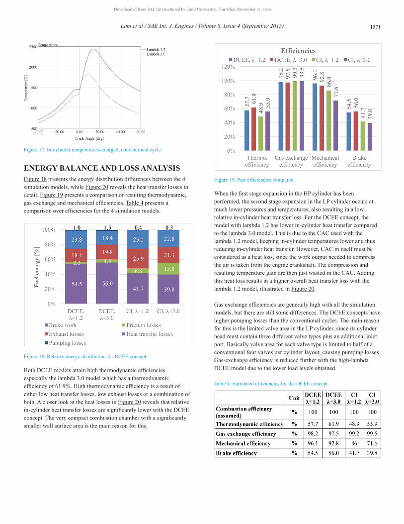
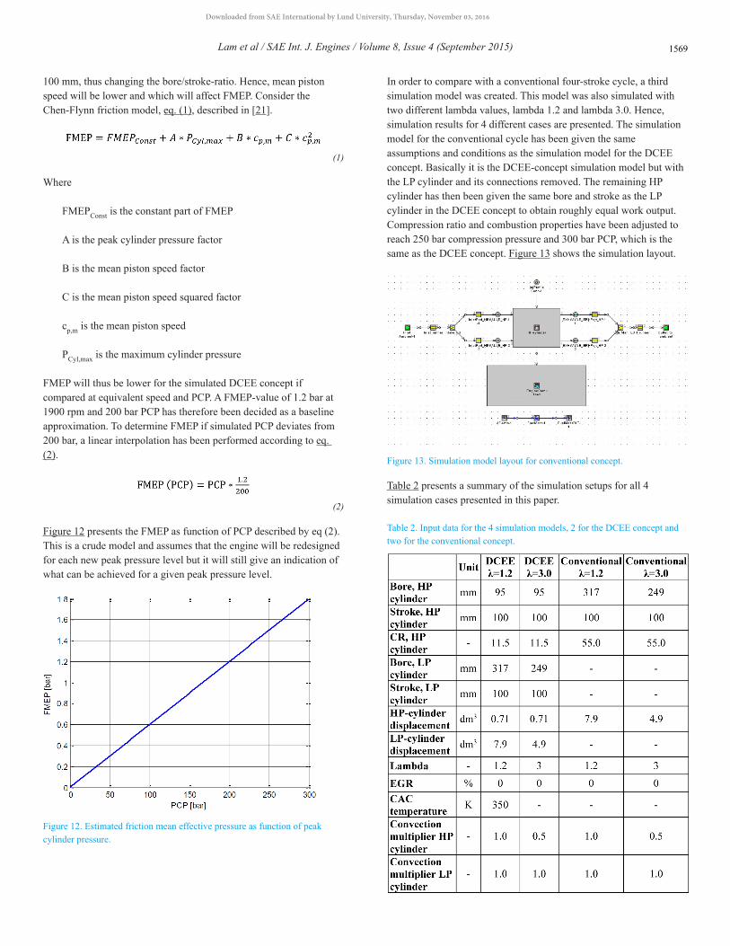
Figure 17. In-cylinder temperatures enlarged, conventional cycle.
ENERGY BALANCE AND LOSS ANALYSISFigure 18 presents the energy distribution differences between the 4 simulation models, while Figure 20 reveals the heat transfer losses in detail. Figure 19 presents a comparison of resulting thermodynamic, gas exchange and mechanical efficiencies. Table 4 presents a comparison over efficiencies for the 4 simulation models.
Figure 18. Relative energy distribution for DCEE concept
Both DCEE models attain high thermodynamic efficiencies, especially the lambda 3.0 model which has a thermodynamic efficiency of 61.9%. High thermodynamic efficiency is a result of either low heat transfer losses, low exhaust losses or a combination of both. A closer look at the heat losses in Figure 20 reveals that relative in-cylinder heat transfer losses are significantly lower with the DCEE concept. The very compact combustion chamber with a significantly smaller wall surface area is the main reason for this.
Figure 19. Part efficiencies compared.
When the first stage expansion in the HP cylinder has been performed, the second stage expansion in the LP cylinder occurs at much lower pressures and temperatures, also resulting in a low relative in-cylinder heat transfer loss. For the DCEE concept, the model with lambda 1.2 has lower in-cylinder heat transfer compared to the lambda 3.0 model. This is due to the CAC used with the lambda 1.2 model, keeping in-cylinder temperatures lower and thus reducing in-cylinder heat transfer. However, CAC in itself must be considered as a heat loss, since the work output needed to compress the air is taken from the engine crankshaft. The compression and resulting temperature gain are then just wasted in the CAC. Adding this heat loss results in a higher overall heat transfer loss with the lambda 1.2 model, illustrated in Figure 20.
Gas exchange efficiencies are generally high with all the simulation models, but there are still some differences. The DCEE concepts have higher pumping losses than the conventional cycles. The main reason for this is the limited valve area in the LP cylinder, since its cylinder head must contain three different valve types plus an additional inlet port. Basically valve area for each valve type is limited to half of a conventional four valves per cylinder layout, causing pumping losses. Gas-exchange efficiency is reduced further with the high-lambda DCEE model due to the lower load levels obtained.
Table 4. Simulated efficiencies for the DCEE concept.
Lam et al / SAE Int. J. Engines / Volume 8, Issue 4 (September 2015) 1571
Downloaded from SAE International by Lund University, Thursday, November 03, 2016
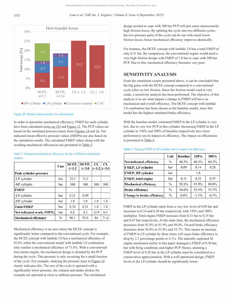
Figure 20. Relative heat transfer loss distribution.
In order to determine mechanical efficiency, FMEP for each cylinder have been calculated using eq. (2) and Figure 12. The PCP values are based on the simulated pressure traces from Figures 14 and 16. Net indicated mean effective pressure values (IMEPn) are also based on the simulation results. The calculated FMEP values along with the resulting mechanical efficiencies are presented in Table 5.
Table 5. Estimated mechanical efficiency for the 4 different simulation models.
Mechanical efficiency is an area where the DCEE concept is significantly better compared to the conventional cycle. For example, the DCEE concept with lambda 3.0 has a mechanical efficiency of 92.8% while the conventional model with lambda 3.0 combustion only reaches a mechanical efficiency of 71.6%. With a conventional four-stroke engine, the mechanical design is dictated by the PCP during the cycle. This pressure is only occurring for a small fraction of the cycle. For example, studying the pressure trace in Figure 16 clearly indicates this. The rest of the cycle is operated with a significantly lower pressure, the exhaust and intake strokes for example are operated at close to ambient pressure. The mechanical
design needed to cope with 300 bar PCP will just cause unnecessarily high friction losses. By splitting the cycle into two different cycles, the low-pressure parts of the cycle can be run with much lower friction losses, hence mechanical efficiency improves drastically.
For instance, the DCEE concept with lambda 3.0 has a total FMEP of only 0.31 bar. By comparison, the conventional engine would need a very high friction design with FMEP of 1.8 bar to cope with 300 bar PCP. Due to this, mechanical efficiency becomes very poor.
SENSITIVITY ANALYSISFrom the simulation results presented above, it can be concluded that the big gains with the DCEE concept compared to a conventional cycle relies on low friction. Since the friction model used is very crude, a sensitivity analysis has been performed. The objective of this analysis is to see what impact a change in FMEP will have on mechanical and overall efficiency. The DCEE concept with lambda 3.0 combustion has been chosen as the baseline model, since this model has the highest simulated brake efficiency.
With the baseline model, estimated FMEP in the LP cylinder is very low, due to very low PCP in this cylinder. Increasing FMEP in the LP cylinder to 150% and 300% of baseline respectively have been performed to see its impact on efficiency. The impact on efficiencies is presented in Table 6.
Table 6. Varying FMEP in LP cylinder and its impact on efficiency.
FMEP in the LP cylinder starts from a very low level of 0.09 bar and increases to 0.14 and 0.28 bar respectively with 150% and 300% multiplier. Total engine FMEP increases from 0.31 bar to 0.35 bar and 0.47 bar respectively. At the same time, the mechanical efficiency decreases from 92.8% to 91.9% and 89.0%. Overall brake efficiency decreases from 56.0% to 55.4% and 53.7%. This means an increase of FMEP in LP cylinder by three times will cause brake efficiency to drop by 2.3 percentage points or 4.1%. The naturally aspirated SI engine mentioned earlier in this paper managed a FMEP of 0.30 bar, but with firing conditions and higher PCP. Hence, attaining a FMEP-level of 0.28 bar in the LP cylinder must be considered as a conservative approximation. With a well optimized design, FMEP levels in the LP cylinder should be significantly lower.
Lam et al / SAE Int. J. Engines / Volume 8, Issue 4 (September 2015)1572
Downloaded from SAE International by Lund University, Thursday, November 03, 2016

Table 7 presents the results of a similar study, but varying FMEP values in the HP cylinder instead. The FMEP value from the baseline model has been multiplied by 150% and 200%. This translates into HP-cylinder FMEP values of 2.7 and 3.6 bar respectively. Since the HP displacement is relatively small compared to the LP cylinder, impact on overall efficiency is not too detrimental. Even with a very high FMEP value of 3.6 bar, brake efficiency drops to a still good level of 52.8%.
Table 7. Varying FMEP in HP cylinder and its impact on efficiency.
Table 8 presents an analysis where FMEP values in both cylinders have been multiplied by 125% and 150% simultaneously. The brake efficiency then drops from 56.0% to 54.9% and 53.8% respectively.
Table 8. Varying FMEP in LP and HP cylinder simultaneously and its impact on efficiency.
SUMMARY/CONCLUSIONSAn engine concept called Double Compression Expansion Engine, DCEE, with a split cycle strategy has been simulated with GT-power 1D-software. Simulations suggest the following:
• The double compression expansion engine concept with lambda 3.0 gives a brake efficiency of 56.0%. With lambda 1.2, brake efficiency of 54.5% is reached. The difference in efficiency is mainly due to higher overall heat transfer losses with close to stoichiometric combustion.
• Very small in-cylinder wall surface area contributes to significantly lower in-cylinder heat transfer losses compared to a conventional engine with a high compression ratio.
• The DCEE concept with lambda 3.0 combustion obtains a thermodynamic efficiency of 61.9%. Low heat transfer loss is the main contributor.
• Due to the need of three different types of valves in the LP cylinder, pumping losses are between 2.5 and 5 times larger for the DCEE concept compared to a conventional four-valve engine. Gas exchange efficiency will be adversely affected.
• A conventional engine using 55:1 compression ratio with lambda 3.0 combustion reaches a thermodynamic efficiency of 55.9%.
• The brake efficiency of the high compression ratio conventional engine suffers mainly from poor mechanical efficiency. High PCP requires a mechanical design with high FMEP. With the high lambda combustion, low load level is obtained which limits mechanical efficiency.
• DCEE-concept friction sensitivity analysis shows that even with very conservative friction estimations, brake efficiency should be well above 50%.
REFERENCES1. Cummins, C.L., Diesel's Engine: From conception to 1918. 1993:
Carnot Press.2. Clarke, J. and O'Malley, E., “Analytical Comparison of a Turbocharged
Conventional Diesel and a Naturally Aspirated Compact Compression Ignition Engine both Sized for a Highway Truck,” SAE Technical Paper 2013-01-1736, 2013, doi:10.4271/2013-01-1736.
3. Phillips, F., Gilbert, I., Pirault, J.-P., and Megel, M., Scuderi Split Cycle Research Engine: Overview, Architecture and Operation. SAE Int. J. Engines, 2011. 4(1)
4. Branyon, D. and Simpson, D., “Miller Cycle Application to the Scuderi Split Cycle Engine (by Downsizing the Compressor Cylinder),” SAE Technical Paper 2012-01-0419, 2012, doi:10.4271/2012-01-0419.
5. Ricardo advancing with two novel heavy-duty vehicle technologies: cryogenic split-cycle engine and microwave fuel reforming. 2013 [cited 2013; Available from: http://www.greencarcongress.com/2013/09/20130904-ricardo.html.
6. Johansson, B., Andersson, Ö., Tunerstål, P., and Tunér, M., Combustion Engines. Vol. 1. 2014.
7. Metzner, D.-I.F.T., Becker, D.-I.N., Demmelbauer-Ebner, D.t.W., Müller, D.-I.R., et al., Der neue 6-l-W12-Motor im Audi A8, in MTZ. 2004
8. Johansson, B., Förbränningsmotorer. 2006, Lund. Eckerle,9. W., Innovate Approaches To Improving Engine Efficiency. 2007: Deer
Conference10. Diesel, M. Two-stroke Low Speed Diesel Engines.11. Megel, M., Westmoreland, B., Jones, G., Phillips, F. et al.,
“Development of a Structurally Optimized Heavy Duty Diesel Cylinder Head Design Capable of 250 Bar Peak Cylinder Pressure Operation,” SAE Int. J. Engines 4(3):2736-2755, 2011, doi:10.4271/2011-01-2232.
12. Borgna, B. Volvo Trucks Announces New Fuel-Efficient 1,850 lb.-ft. Torque Rating for D13 Engine. Available from: http://www.volvotrucks.com/trucks/na/en-us/_layouts/CWP.Internet.VolvoCom/NewsItem.aspx?News.ItemId=140962&News.Language=en-gb.
13. Manente, V., Johansson, B., Tunestal, P., and Cannella, W., “Effects of Different Type of Gasoline Fuels on Heavy Duty Partially Premixed Combustion,” SAE Int. J. Engines 2(2):71-88, 2010, doi:10.4271/2009-01-2668.
14. Atkinson, J., atkinson patent. 1887, Google Patents15. Johnson, B. and Edwards, C., “Exploring the Pathway to High
Efficiency IC Engines through Exergy Analysis of Heat Transfer Reduction,” SAE Int. J. Engines 6(1):150-166, 2013, doi:10.4271/2013-01-0278.
16. Conklin, J.C. and Szybist, J.P., A highly efficient six-stroke internal combustion engine cycle with water injection for in-cylinder exhaust heat recovery. Energy, 2010. 35(4)
17. Hyvönen, J., Wilhelmsson, C., and Johansson, B., “The Effect of Displacement on Air-Diluted Multi-Cylinder HCCI Engine Performance,” SAE Technical Paper 2006-01-0205, 2006, doi:10.4271/2006-01-0205.
Lam et al / SAE Int. J. Engines / Volume 8, Issue 4 (September 2015) 1573
Downloaded from SAE International by Lund University, Thursday, November 03, 2016

18. Manente, V., Tunestal, P., Johansson, B., and Cannella, W., “Effects of Ethanol and Different Type of Gasoline Fuels on Partially Premixed Combustion from Low to High Load,” SAE Technical Paper 2010-01-0871, 2010, doi:10.4271/2010-01-0871.
19. Tuner, M., Johansson, B., Keller, P., and Becker, M., Loss Analysis of a HD-PPC Engine with Two-Stage Turbocharging Operating in the European Stationary Cycle. 2013, SAE International
20. Fridriksson, H., Sundén, B., Hajireza, S., and Tunér, M., CFD Investigation of Heat Transfer in a Diesel Engine with Diesel and PPC Combustion Modes. 2011, SAE International
21. Gamma Technologies Inc., GT-Suite, GT-ISE Version 7.3, Computer Software.
22. Noble, A. and Such, C., Ways to reduce CO2 emissions from on-highway, heavy duty diesel engines, in Transport Research Arena. 2014, Ricardo UK Ltd: Paris
CONTACT INFORMATIONNhut LamPhD. Student, Division of Combustion EnginesDepartment of Energy SciencesLund UniversityLund, Sweden+46 46 [email protected]
ABBREVIATIONSBMEP - Brake Mean Effective Pressure
CAC - Charge Air Cooler
CAD - Crank Angle Degree
CI - Compression Ignited
EGR - Exhaust Gas Recycling
FMEP - Friction Mean Effective Pressure
HCCI - Homogenous Charge Compression Ignition
HTL - Heat Transfer Losses
ICE - Internal Combustion Engine
IMEPg - Gross Indicated Mean Effective Pressure
IMEPn - Net Indicated Mean Effective Pressure
LHR - Low Heat Rejection
LTC - Low Temperature Combustion
NA - Naturally Aspirated
PCP - Peak Cylinder Pressure
PMEP - Pumping Mean Effective Pressure
PPC - Partially Premixed Combustion
SI - Spark Ignited
TDC - Top Dead Center
TDCF - Firing Top Dead Center
VGT - Variable Geometry Turbine
Lam et al / SAE Int. J. Engines / Volume 8, Issue 4 (September 2015)1574
Downloaded from SAE International by Lund University, Thursday, November 03, 2016

APPENDIX
Appendix A- Definitions Of Mean Effective Pressures And Engine Efficiencies
Figure A1. Sankey-diagram from the conversion of fuel energy to brake work.
Fuel Mean Effective Pressure, FuelMEPThe first thing we must do is to feed the engine with some fuel. The fuel energy per cycle is given by the mass of fuel added per cycle times its heating value. The resulting energy should then be divided by the displacement volume to get a pressure. We get
(1)
where
mf = mass of fuel per cycle [kg]
QLHV = Lower heating value of the fuel [J/kg]
VD = Displacement volume [m3]
Heat Mean Effective Pressure, QMEPAfter feeding the engine cylinder with fuel the next step is to convert the chemically bonded energy to heat. The combustion process as such is very complex and will require much explanation before the reader can get a reasonable grasp on the process. This is however not needed in this phase of the discussion. In a thermodynamic sense the only task of the combustion process is to convert the fuel energy to heat. The heat energy is expressed in Joules per cycle or if normalized by the displacement volume in the same way as for FuelMEP we get the heat mean effective pressure, QMEP as
(2)
where
Q = amount of heat added per cycle [J]
VD = displacement volume [m3]
Lam et al / SAE Int. J. Engines / Volume 8, Issue 4 (September 2015) 1575
Downloaded from SAE International by Lund University, Thursday, November 03, 2016

Gross Indicated Mean Effective Pressure, IMEPgThe definition using only compression and expansion strokes is called gross indicated mean effective pressure, IMEPgross or IMEPg
(3)
where the integration starts at BDC and ends at BDC+360 crank angle degrees, CAD, later.
The compression work is defined as:
(4)
And the expansion work is:
(5)
Net Indicated Mean Effective Pressure, IMEPnThe definition using all for strokes is called net indicated mean effective pressure, IMEPnet or IMEPn and is thus expressed as
(6)
Brake Mean Effective Pressure, BMEPBMEP is defined as the useful energy produced by the engine per cycle divided by the displacement volume as
(7a)
but it can also be expressed in terms of Power [W] per displacement and time as
(7b)
Where
P = Engine power [W]
N = Engine speed [rps]
nT = Stroke factor [-]
VD = Displacement Volume [m3]
The stroke factor is 1 for two-stroke engines and 2 for four-stroke engines. It is used to get similar values for BMEP for the two types of engines and also to compensate for the four-stroke engine only giving positive work every second revolution.
Lam et al / SAE Int. J. Engines / Volume 8, Issue 4 (September 2015)1576
Downloaded from SAE International by Lund University, Thursday, November 03, 2016

Combustion Loss Mean Effective Pressure, CLMEPThe combustion losses can be expressed as a mean effective pressure as well. It is defined as
(8)
Heat Transfer Loss Mean Effective Pressure, HTMEPThe heat transfer losses can be expressed as a mean effective pressure as
(9)
where
QHT= Heat transfer losses [J]
Exhaust Loss Mean Effective Pressure, EXMEPThe exhaust losses can be expressed as a mean effective pressure as
(10)
where
QEX= Exhaust energy losses [J]
Pumping Loss Mean Effective Pressure, PMEPThe pumping losses can be expressed as the difference between gross indicated mean effective pressure and net indicated mean effective pressure:
(11)
Friction Loss Mean Effective Pressure, FMEPThe friction losses can be expressed as the difference between net indicated mean effective pressure and brake mean effective pressure:
(12)
Combustion Efficiency, ηCThe combustion efficiency is how much heat that can be generated by the combustion of a fuel. It is defined as
(13)
Thermodynamic Efficiency, ηTThe thermodynamic efficiency is defines as
(14)
Lam et al / SAE Int. J. Engines / Volume 8, Issue 4 (September 2015) 1577
Downloaded from SAE International by Lund University, Thursday, November 03, 2016

Gas-Exchange Efficiency, ηGE
(15)
Mechanical Efficiency, ηMMechanical efficiency is defined as
(16)
Brake Efficiency, ηBMechanical efficiency is defined as
(17)
All rights reserved. No part of this publication may be reproduced, stored in a retrieval system, or transmitted, in any form or by any means, electronic, mechanical, photocopying, recording, or otherwise, without the prior written permission of SAE International.
Positions and opinions advanced in this paper are those of the author(s) and not necessarily those of SAE International. The author is solely responsible for the content of the paper.
Lam et al / SAE Int. J. Engines / Volume 8, Issue 4 (September 2015)1578
Downloaded from SAE International by Lund University, Thursday, November 03, 2016