Double Column Machining Centers - Premium CNC Metal ... · History of Okuma double column machining...
15
Double Column Machining Centers
Transcript of Double Column Machining Centers - Premium CNC Metal ... · History of Okuma double column machining...

Double Column Machining Centers

1 2
In 1964 Okuma introduced the first double-column machining
center. In the almost 50 years since then, we have shipped
over 8,000 units into a wide range of industrial markets. We
have earned the trust of manufacturers and built a solid
reputation of quality, reliability and service.
Okuma’s “total responsibility approach” combines electrical,
mechanical and control technology, high product quality,
machining know-how and ease-of-use. This provides high-
rigidity, high accuracy and a product line that our customers
can count on.
Okuma stays ahead of other machine tool manufacturers with
a consistent approach to the art of manufacturing, employing
“Only One” technologies to produce a full line of double-
column machining centers for nearly any large part
application.
Testament to trust
Expand your expectationsOkuma double column machining. A really big idea whose time has come.

3 4
Photos in this brochure may include optional equipment.
Okuma double column machining centers provide the stability and power required to deliver supersized precision. That’s why detail-oriented industries such as aerospace, electronics, and automotive rely on Okuma to generate accurately machined parts, time and again.
Big Time Production
High rigidity, high output High performance, high accuracy
Linear motor drive, high speed Space-saving, high-speed vertical Quill type vertical
Superior cost performance, multifunctional
Space-saving,superior cost performance

5 6
1964 1970 1972 1974 19911977 1978 1983 1994 1997 2001 2004 2006 2007 2008 2011 2012
Our history of technology development and delivery performance tell the story of quality and reliability
Four keys to the art of manufacturingOkuma’s approach to the art of manufacturing is to provide customers with
high quality, high accuracy products that cannot be matched by others.
This is where we earn customers’ trust, and it is the reason we have the
support of so many.
MCR-BII[5-sided]
■History of Okuma double column machining centers
First die manufacturing system (DMS) withTM-APT-GM auto programmingsystem
JP-type NC boring face milling machines
MCV MCV-A MCV-AII
MCM [5-sided applications]
MCR for 5-sided applications with auto head changers
Okuma's first CNC (OSP 2000) used on the MDB-N
MCR-H high speed machine with linear drive system
Thermo-Friendly Concept for double-column machining centers
MCR-BIII[5-sided]
MCR-A[5-sided]
MCR-A5C[5-sided]
MCR-C[5-sided]
MCR-A5CII[5-sided]
Total shipments of double columns reached 6,000
K5 factory at Kani Plant completed, and with K4 factory achieves start-to-finish production of double columns
Since first introducing Okuma double column machining centers in 1964, we have shipped more than
8,000 units. Today, Okuma boasts a 50%* share of the double-column machining center market.
In the die/mold machining market, our share exceeds 60%*. We will continue to respond to the
confidence shown by customers with double-column machining centers that help them achieve their
ideal form of machining. * Orders received by Japan Machine Tool Builders’ Association members.
Okuma builds the complete package—from machines to controls, motors, and encodersTotal responsibility
Designed for optimum rigidity and higher machining accuracy
Quality engineered production processes
Providing the highest machining accuracy and productivity to customersOkuma’s “Only One” technology
1
2
3
4

7 8
The elevating crossrail has sufficient length and a structure for accuracy and long life with no "snaking" movement.
Double-column construction with square columns maintains good rigidity with respect to vertical loads, horizontal loads, and torsion for heavy-duty cutting with high accuracy.
Square column double-column construction
Spindlehead (ram saddle) guideway
Roller guide system for table guide
Crossrail clamp
Elevating crossrail guideway
Powerful clamping device in which the lever principle is applied to the crossrail clamp.
The spindlehead guide has a wide, highly rigid rectangular cross section, and is supported by a deadweight balancer via rollers on the crossrail. This gives high speed, high accuracy movements and high quality machined surfaces.
The weight of the table and workpiece is supported with roller bearings on hardened and ground surfaces. Movement is not affected by weight changes from heavy workpiece loads, enabling light, smooth movements and accurate positioning. Layout includes the drive system (ball screw) in the table center with a narrow width between the center guides, to achieve outstanding linear motion straightness and long-term stability.
Solid performance achieved byadvanced structural designs
Saddle guideway
Elevating crossrail guideway
Crossrail clamp
Roller guideway
Table
Bed
Crossrail RollerSaddle
Ram Deadweight balancer
Spring
Narrow width between the center guides

9 10
■B-/C-axis universal index head
■Extension head
■90º angular head
Full array of headsAll types of cutting in all types of shapes can be machined by changing the wide array of heads.
Many different processes can be performed in auto operation with the auto tool changer (ATC) and auto head changer (AAC).
Automation for highly productive and flexible performance
Smaller and faster AAC
Completely automate machining of multiple sides with a variety of heads that mount automatically and accept ATC.
Fast NC-ATC
One arm performs the changes for both the horizontal and vertical spindles. The next tool to be used, regardless of the spindle location, is brought to the standby position during cutting. This simultaneous operation greatly reduces tool-to-tool time. ATC is available for 30°angular
heads and universal index heads (B/C axis) in addition to extension heads and 90° angular heads.
Extension head tool change 90º angular head tool change Universal index head tool change
168
90ºB-axis swing
range175
ø220
240
415
267 15
0
450
180 270
ø220
250
Various applications for higher productivity and comfortable operation
● Hinged full-length chip conveyors +collection conveyor
● Hinged half-length chip conveyors +chip bucket
● Full-length gutter system + chip pan
■Examples of chip conveyor placement
Chip panCollection conveyor Chip bucket
Table-side conveyorsTable-side conveyorsTrough Trough
Machine Machine Machine
■Common collection conveyorsType
Shape
Hinge Scraper Magnet scraper Hinge + scraper (with drum filter)
Full-enclosure shielding(w/o ceiling)
100-tool ATC magazineSide-shuttle 2-pallet APC
■These and other options available*1
Table-side conveyor
Collection conveyor
*1. See separate product brochures for detailed descriptions and specifications.
Magnet
* Conveyor flow direction (rear), off-machine conveyor flow direction (operator or magazine side), chip coolant tank position, and other factors can be considered to meet space requirements.

11 12
Xaxis
Yaxis
Zaxis
Sensor information Spindle operation information
Calculation
Dimensional compensationcommand
From theory to effective machine applicationsOkuma’s Intelligent Technology
● Integrated machine design and control technologyThe Thermo-Friendly Concept plays a principal role in our machine design. With simple machine designs and construction that equalize ambient temperatures, deformation is predictable, and complex torsion or tilting is controlled. Moreover, highly accurate compensation technology (Okuma control [OSP] award winning innovation) effectively responds to deformation caused by changes in room temperature, frequent spindle speed changes, and non-coolant cutting.With the Thermo-Friendly Concept (Manageable Deformation—Accurately Controlled), Okuma products provide unrivaled dimensional stability.
Thermo-Friendly Concept
• Thermo Active Stabilizer––Spindle (TAS-S)Thermal deformation from spindle rotation controlled with high accuracy.
• Thermo Active Stabilizer––Table (TAS-T)Control of deformation from thermal expansion of table.
Thermo-Friendly Concept
• Thermo Active Stabilizer––Spindle (TAS-S) • Thermo Active Stabilizer––Construction for large
machines (TAS-C2)
The machine is optimally controlled to maintainmachining accuracies even when ambient temperatures change.
Thermo-Friendly Premium Specs
• “Manageable” thermal deformation construction (controlled vertical thermal growth without tilting)
• Thermo Active Stabilizer––Table (TAS-T)
TAS-S : Thermo Active Stabilizer––Spindle
TAS-T : Thermo Active Stabilizer––Table
TAS-C2 : Construction (TAS-C) + TAS-T
TAS-C : Thermo Active Stabilizer––Construction
Spindle
Ram
Coolant
00
0-10
10
0-10
10
0-10
10
5 10 15
μm
min
-1D
efor
mat
ion
Sp
ind
le s
pee
d
Operation h
■Actual results with TAS-S (30º angular head, 30,000 min-1)
30,000 30,000 30,000 30,000 30,000
10,000 5,000 2,000
X axis
Y axis
Z axis
With Thermo-Friendly Premium
Must find origin every time before machining multi-quantity parts (misalignment from workpiece origin:100 μm)
Previous machine
● Example of parts machiningResult
Confirmation only OK!(misalignment from workpiece origin: 20 μm)Huge reduction in zero offsets
Workpiece No. 2Workpiece No. 1
Machine table
Environmental economic benefits ofOkuma’s Thermo-Friendly Concept
In environments with normal temperature changes, machining accuracies equivalent to those in temperature-controlled rooms are achieved. As long as the operator is comfortable, there is no need for air conditioning to ensure accuracy.
■Amount of energy consumed for temperature-controlled room
Savings of approximately 43,400 kWh(*1)
Prevents CO2 emissions equivalent to about 24,300 beech trees per year
Ecology & Economy
*1. Calculations are examples only, and may differ from actual circumstances. Temperature-controlled room capacity: 30 m x 15 m x H8 m ±0.5ºC*2. Monozukuri: Making things –– better than ever
Thermo-Friendly Concept
Energy-saving function Energy-saving technology
Machines and technology to achieve eco-friendly "monozukuri"*2
NC unit power consumption (%)
0
20
40
60
80
100
120(%)
136%
100%
43%
OSP ofthe 1990s
OSP of the 2000s
OSP-P300
Power consumption
(compared to previous Okuma machine)Reduced 60%
●Allowing operators to focus on making partsNC controller (OSP) with 3D model data of machine components –– workpiece, tool, fixture, head –– performs real time simulation just ahead of actual machine movements. It checks for interference or collisions, and stops the machine movement immediately before collision. Machinists (novice or pro) will benefit from reduced setup and trial cycle times, and the confidence to focus on making parts.
Collision Avoidance System
●Maximizing machine tool performanceBased on the chatter noise captured by the microphone, Machining Navi displays a number of optimal spindle speed possibilities on the screen. The operator can change to the indicated spindle speed with a single touch and immediately confirm the result.
Machining Navi M-g
Chatter noise displayed
One of the proposed spindle speeds is selected and confirmed with a single touch

The touch sensor screen pops up from the tool registration screen. Tool compensation values are set while looking at a guidance message.
13 14
2.0μm 2.0μm
Satisfaction from complete control of a machine tool
■Setup operations
■Trial/continuous cuts■Programming ■Tool preparations
As a “machine & control” builder, Okuma makes further strides in machine tool manufacturing with
this superb, control featuring “Easy Operation”. Okuma took a close look at the way machinists
actually operate machine tools, to help them create smoother and more effective ways of producing
parts. Novice operators as well as professional machinists get complete control—and satisfaction.
Moreover, what you want to see and do conveniently come together in a “single-mode operation”.
First, select one of three operation screens. Then simply touch the screen or press a function key to
see and do your job.
With spreadsheet simplicity —tool offsets, tilt, shape, life, etc—all the tool data required to cut a part can be registered here.Since the registered tool data is also used by Okuma auto programming (Advanced One-Touch IGF) and a collision check function (Collision Avoidance System), this screen will complete the entire registering process.
Okuma’s CNC OSP-P300M
Easy tool registration
The Okuma OSP Control is essentially the “mechatronic” solution for tough machine shop requirements
PFC Projection Flat Control
Lost motion and backlash from axis reverse movements occur at various speed levels.PCF II dynamically flattens out spikes when circular quadrants switch.
Fast contouring Super-NURBS
With the latest development (Sculptured Surface Adaptive Acceleration Control), a variety of free forms can be machined to high accuracy and quality by this fast CNC function.
■Before
■Super-NURBS
Shaping feedrates much faster
Position
Position
Feed
rate
Feed
rate
Much faster acceleration
Feed axis bending compensation
Bending is caused by expansion/contraction and torsion of the drive system. Unevenness from reciprocating movement can be minimized by compensating for bending produced during acceleration and deceleration. This is particularly effective in die/mold machining.
Technology that combines machine and control to give high-speed, high-accuracy machining
+Y
+X
+Y
+X
Projection: 8.1 1.4 μm
Previous control
ø100 mm, feedrate: 8,000 mm/min
With PFC II
G44 X Y Z I J K D
Previous control Bending compensationapplicable
When it is difficult to program feedrates for die-making and you need different feedrates for specific cutting patterns, you can simply program using feedrate numbers. Choose either the rotary switch or the keyboard type F1 parameters.
Parameter F1 digit
Set 3-dimensional tool offsets by commanding the I, J, and K offset directions with the coordinates.
Resume cutting either from the beginning or midway into a desired block.
3-D tool compensation Mid-block restart
15 16
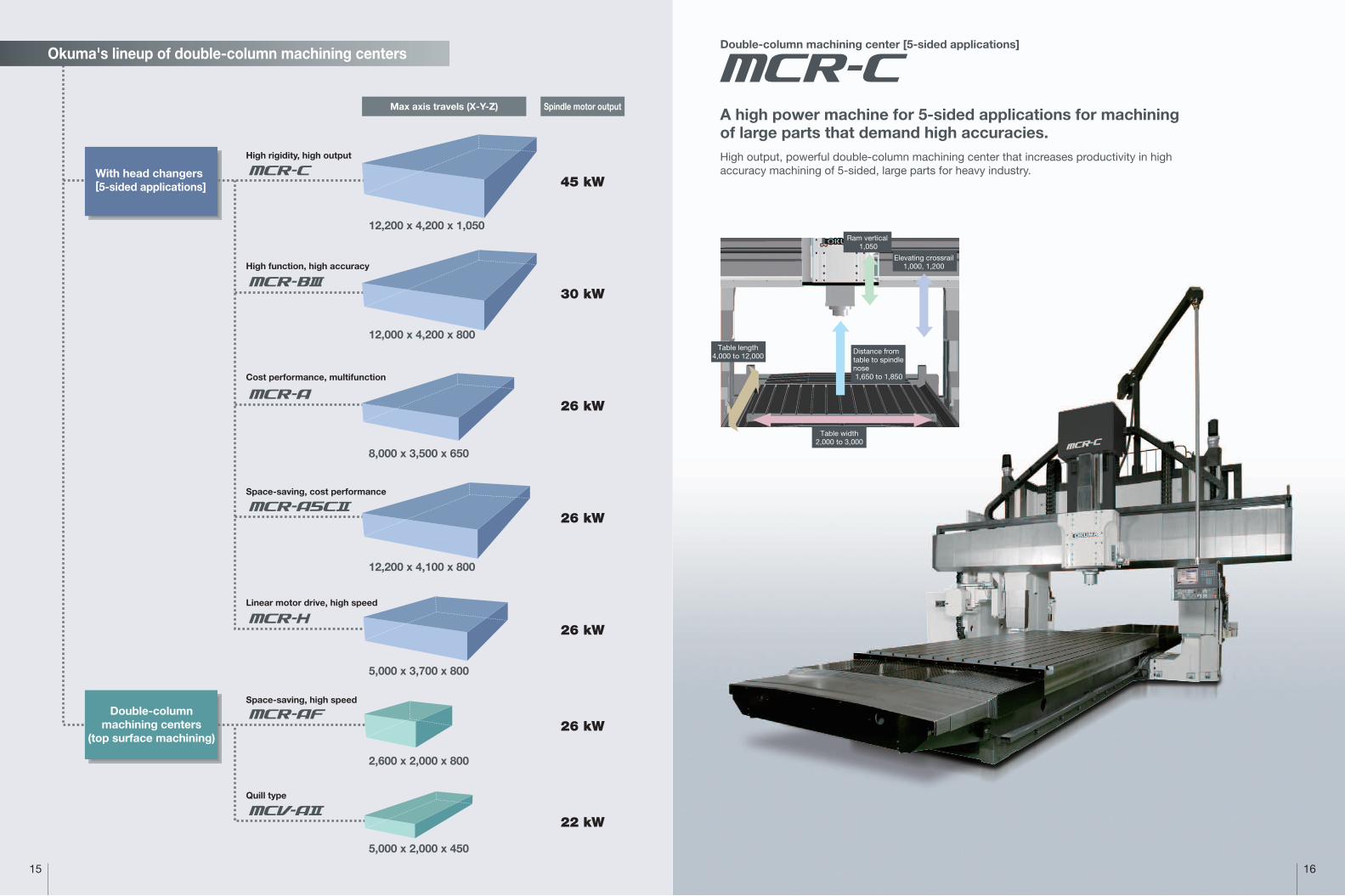
Okuma's lineup of double-column machining centers
2,600 x 2,000 x 800
5,000 x 2,000 x 450
5,000 x 3,700 x 800
12,200 x 4,100 x 800
12,000 x 4,200 x 800
12,200 x 4,200 x 1,050
8,000 x 3,500 x 650
45 kW
30 kW
26 kW
26 kW
26 kW
26 kW
22 kW
With head changers[5-sided applications]
Double-columnmachining centers
(top surface machining)
High function, high accuracy
High rigidity, high output
Cost performance, multifunction
Space-saving, cost performance
Linear motor drive, high speed
Quill type
Space-saving, high speed
Max axis travels (X-Y-Z) Spindle motor output
Double-column machining center [5-sided applications]
Table length4,000 to 12,000
Table width2,000 to 3,000
Ram vertical 1,050
Elevating crossrail1,000, 1,200
A high power machine for 5-sided applications for machining of large parts that demand high accuracies.High output, powerful double-column machining center that increases productivity in high accuracy machining of 5-sided, large parts for heavy industry.
Distance from table to spindle nose1,650 to 1,850
15 16
Okuma's lineup of double-column machining centers
2,600 x 2,000 x 800
5,000 x 2,000 x 450
5,000 x 3,700 x 800
12,200 x 4,100 x 800
12,000 x 4,200 x 800
12,200 x 4,200 x 1,050
8,000 x 3,500 x 650
45 kW
30 kW
26 kW
26 kW
26 kW
26 kW
22 kW
With head changers[5-sided applications]
Double-columnmachining centers
(top surface machining)
High function, high accuracy
High rigidity, high output
Cost performance, multifunction
Space-saving, cost performance
Linear motor drive, high speed
Quill type
Space-saving, high speed
Max axis travels (X-Y-Z) Spindle motor output
Double-column machining center [5-sided applications]
Table length4,000 to 12,000
Table width2,000 to 3,000
Ram vertical 1,050
Elevating crossrail1,000, 1,200
A high power machine for 5-sided applications for machining of large parts that demand high accuracies.High output, powerful double-column machining center that increases productivity in high accuracy machining of 5-sided, large parts for heavy industry.
Distance from table to spindle nose1,650 to 1,850

17 18
Double-column machining center [5-sided applications]
Machine for 5-sided applications with true multi-functionality and cost performance that combines high functionality and economyHigh value-added production of general machine parts in many different kinds of machining with a wide array of heads
Double-column machining center [5-sided applications]
This large high-tech machine features a powerful square-ram spindle with a wide selection of heads available for fully automatic 5-sided applications.Offering top-class operations in heavy-duty cutting of large components as well asstate-of-the-art quality for die/mold applications
Table length2,800 to 11,800
Table width1,500 to 3,000
Ram vertical 800
Elevating crossrail700 to 1,300
Distance from table to spindle nose1,350 to 1,850
Table length3,000 to 7,800
Table width1,500 to 2,500
Ram vertical 650
Elevating crossrail700 to 1,300
Distance from table to spindle nose1,350 to 1,950

19 20
Table length3,800, 4,800
Table width2,000, 2,500
Ram vertical 800
Elevating crossrail1,000, 1,300
Distance from table to spindle nose
1,550, 1,750
Table length3,000 to 12,000 Distance from table
to spindle nose1,450 to 1,850
Table width1,500 to 3,000
Ram vertical800
Elevating crossrail800 to 1,200
Double-column machining center [5-sided applications]
High speed, high accuracy 5-sided machining applications with linear motor take performance to the next dimensionBreaking through to a new machining dimension with high speed cutting feed using Okuma-developed linear motors on the X and Y axes, and outstanding thermal stability
Double-column machining center [5-sided applications]
Agile and highly efficient with 2-station AACA compact machine for cost-effective 5-sided applicationsCan also be extended to a 4-station AAC model, still compact, with quicker load/unload times for more productive machining of general machine components.

21 22
Double-column machining centerDouble-column machining center
Quill-type double-column machining center with light, comfortable operabilityThe best machine for highly efficient machining of medium size general machine parts Streamlines production from powerful heavy-duty cutting to high speed finishing
Fixed crossrail and 800 mm Z axis travel Space-saving, high speed double-column machining centerHigh-speed, high-accuracy machining of medium-sized and large dies/molds and parts High-speed spindle and long Z-axis travel also handles shapes with large height changes
Table length1,800 to 5,000
Table width1,200, 1,500
Quill vertical 450
Elevating crossrail1,000, 1,150
Distance from table to spindle nose1,360 to 1,510
Table lengths1,500, 2,000
Table width2,000
Ram vertical 800
Distance from table to spindle nose
300 to 1,100

23
4,200 to 12,200
3,200 to 4,200
1,050 [1,250]
1,000, 1,200
2,650 to 3,650
1,650 to 1,850
[1,550 to 1,750] *1
2,000 × 4,000 to
3,000 × 12,000
22,000 to 66,000
24H7 × 11, 13, 15
(Center 200)
850 to 950
X-Y: 24, Z: 15
(X-Y: 24*2, Z: 15) *3
(X: 20, Y: 24*2, Z: 15) *4
1 to 10,000
3,000
MAS BT50
MAS 2
50
[80, 100, 120, 180]
W/ adjacent tools: ø135
W/o adjacent tools: ø264
600
25
Fixed address
3,000 to 12,000
2,700 to 4,200
800 [1,000]
700 to 1,300
2,050 to 3,550
1,350 to 1,850
[1,250 to 1,750] *1
1,500 × 2,800 to
3,000 × 11,800
12,000 to 72,600
24H7 × 9 to 15
(Center 200)
800 to 950
X: 15, Y: 20*10, Z: 15
1 to 10,000
3,000
MAS BT50
MAS 2
32*11
[50, 72, 100, 120, 180]
W/ adjacent tools: ø135
W/o adjacent tools: ø230
400
25
Fixed address
3,200 to 8,000
2,500 to 3,500
650 [800]
700 to 1,300
2,050 to 3,050
1,350 to 1,950
[1,250 to 1,850] *1
1,500 × 3,000 to
2,500 × 7,800
10,000 to 35,000
20H7 × 11 to 24H7 × 13
(Center 140, 200)
750 to 850
X-Y: 20, Z: 10
1 to 10,000
1,000
MAS BT50
MAS 2
32
[50, 72, 100, 120, 180]
W/ adjacent tools: ø135
W/o adjacent tools: ø230
400
25
Fixed address
24
MCR-B MCR-AMCR-C MCR-A5C MCR-H MCR-AF MCV-A
3,200 to 12,200
2,600 to 4,100
800
800 to 1,200
2,150 to 3,650
1,450 to 1,850
[1,350 to 1,750] *1
1,500 × 3,000 to
3,000 × 12,000
12,000 to 66,000
20H7 × 11 to 24H7 × 15
(Center 140, 200)
850 to 950
X: 30, Y: 32, Z: 20
(X: 30, Y: 32*2, Z: 20) *20
(X: 20, Y: 32*2, Z: 20) *21
(X: 30, Y: 30*2, Z: 20) *22
(X: 20, Y: 30*2, Z: 20) *23
1 to 10,000
3,000
MAS BT50
MAS 2
50
[80, 100, 120, 180]
W/ adjacent tools: ø135
W/o adjacent tools: ø230
400
25
Fixed address
4,000, 5,000
3,200, 3,700
800
1,000, 1,300
2,550, 3,050
1,550, 1,750
2,000 × 3,800,
2,500 × 4,800
22,000, 33,000
24H7 × 11, 13
(Center 200)
1,020, 1,070
X-Y: 30, Z: 15
X-Y: 1 to 30,000, Z: 1 to 15,000
5,000
MAS BT50
MAS 2
50
[32, 72, 100, 120, 180]
W/ adjacent tools: ø135
W/o adjacent tools: ø230
400
25
Fixed address
2,600
1,500, 2,000
800
−
2,600
1,100
[1,000*29]
2,000 × 1,500,
2,000 × 2,000
10,000
20H7 × 9, 11
(Center 200)
850
X-Y: 20, Z: 10
1 to 10,000
−
MAS BT50 [MAS BT50*29, MAS BT40*30, HSK-A63*31*32]
MAS 2*33
24
[32*30*31*32, 48*30*31*32, 50*34, 72*34, 100*34]
W/ adjacent tools: ø125*34 [ø135*35, ø90*30*31*32]
W/o adjacent tools: ø230*34 [ø125*30*31*32]
400
25*34 [8*30*31*32]
Fixed address*34 [random memory*30*31*32]
2,000 to 5,000
1,600, 2,000
450 (Quill vertical)
1,000, 1,150
1,650, 2,050
1,360 to 1,510
[1,380 to 1,530] *36
1,200 × 1,800 to
1,500 × 5,000
6,000 to 20,000
20H7 × 9, 11
(Center 140)
700 to 800
X-Y: 20, Z: 10
1 to 10,000
420/500 (50/60Hz)*37
MAS BT50
MAS 2
24
[50, 72, 100]
W/ adjacent tools: ø128
W/o adjacent tools: ø230
400
20
Fixed address
15
20
30
40
50
65
80
100
120
16 20 25 30 35
Width between columns(Y-axis)
15
20
30
40
50
65
80
100
120
16 20 25 30 35
15
20
30
40
50
65
80
100
120
16 20 25 30 35
15
20
30
40
50
65
80
100
120
16 20 25 30 35
15
20
30
40
50
65
80
100
120
16 20 25 30 35
15
20
30
40
50
65
80
100
120
16 20 25 30 35
15
20
30
40
50
65
80
100
120
16 20 25 30 35
MACHINE SPECIFICATIONSMCR-B MCR-AMCR-C MCR-H MCR-AF MCV-AMCR-A5C*9
Travel
X-axis travel (table front/back)
Y-axis travel (spindle horizontal)
Z-axis travel (ram vertical)
W-axis travel (crossrail vertical)
Effective width between columns
Table to spindle nose (max)
Table
Working surface
Maximum load
T-slots
[Width x No. (spacing)]
Height from the floor
Feedrates
Rapid traverse
Cutting feedrate
W-axis (crossrail vertical)
ATC
Tool shank
Pull stud
Tool magazine capacity
Max tool diameter
Max tool length
Max tool weight
Tool selection
mm
mm
mm
mm
mm
mm
mm
kg
mm
mm
m/min
mm/min
mm/min
tools
mm
mm
kg
[ ]: Optional
: Fixed crossrail
: Elevating crossrail
■Nominal sizes:
Tab
le t
rave
l (X
-axi
s)
Width between columns(Y-axis)
Tab
le t
rave
l (X
-axi
s)
Width between columns(Y-axis)
Tab
le t
rave
l (X
-axi
s)
Width between columns(Y-axis)
Tab
le t
rave
l (X
-axi
s)
Width between columns(Y-axis)
Tab
le t
rave
l (X
-axi
s)
Width between columns(Y-axis)
Tab
le t
rave
l (X
-axi
s)
Width between columns(Y-axis)
Tab
le t
rave
l (X
-axi
s)

25 26
4,000 [6,000]
7/24 Taper No. 50
ø100 [ø85*5, ø130*6, ø100*7]
VAC 45/37 (30 min/cont)
[37 (cont)] *5
X: 14.0, Y: 9.4, Z: 5.2 × 2
W: 4.6 × 2
60*8
650 (over 0.5 MPa) *8
6,730, 6,980
7,810 × 10,730 to
8,835 × 28,420
44,000 to 108,000
OSP-P300M
4,000 [3,600, 6,000, 8,000, 10,000]
7/24 Taper No. 50
ø100 [ø85*12]
VAC 30/22 (30 min/cont) *8
[45/37 (30 min/cont) *13, 22 (cont) *5
26/22 (30 min/cont) *14]
X: 9.4 (14*15), Y: 7.3, Z: 4.6 × 2
(X: 9.4 (14*16), Y: 9.4, Z: 4.6×2)*17
W: 4.6 (5.2*18) × 2
60*8
650 (over 0.5 MPa) *8
6,250 to 6,850
6,950 × 8,200 to
8,700 × 27,400
36,000 to 120,900
OSP-P300M
4,000 [6,000, 8,000, 10,000]
7/24 Taper No. 50
ø100 [ø85*12]
VAC 26/22 (30 min/cont)
X-Y: 4.6 (9.4*19), Z: 3.6
W: 4.2
60*8
650 (over 0.5 MPa) *8
5,550 to 6,350
6,595 × 8,350 to
7,860 × 18,800
35,000 to 64,000
OSP-P300M
4,000 [6,000, 10,000]
7/24 Taper No. 50
ø100[ø85*24]
VAC 26/22 (30 min/cont) *8
[26/22 (30 min/cont) *24, 30/22 (30 min/cont) *25]
X: 9.4 (14*26), Y: 7.3, Z: 5.2 × 2
W: 4.6 × 2
60*8
650 (over 0.5 MPa) *8
5,820 to 6,300
6,180 × 8,430 to
7,780 × 28,420
31,000 to 100,000
OSP-P300M
8,000
7/24 Taper No. 50
ø85
VAC 26/22 (30 min/cont)
X: 12*27, Y: 6*27, Z: 4.6 × 2
W: 5.1 × 2
80*8
1,370 (over 0.5 MPa) *8
6,800, 7,120
7,790 × 10,500,
8,290 × 12,500
68,000*28
OSP-P300M
8,000 [12,000, 15,000, 20,000, 25,000]
7/24 Taper No. 50
[7/24 Taper No.50*29, 7/24 Taper No.40*30, HSK-A63*31*32]
ø85 [ø100*29*30, ø70*31, ø60*32]
VAC 26/22 (30 min/cont)*8
[37/26 (10 min/cont) *29, 22/18.5 (10 min/cont) *30,
30/22 (10 min/cont)*31, 15/11 (10 min/cont) *32]
X-Y: 5.0, Z: 3.6 × 2
−
55*8
700 (over 0.5 MPa) *8
4,670 [4,450*29]
5,560 × 4,200,
5,560 × 5,230
24,500, 26,000
OSP-P300M
4,000 [6,000, 10,000]
7/24 Taper No. 50
ø100 [ø85*24]
22/18.5 (30 min/cont)
[22/15 (30 min/cont)*5, 22 (cont)*25]
X: 3.5 (4.2*38, 4.6*39)
Y: 4.2, Z: 4.2
3.7 (AC) [3.6*40]
50*8
500 (over 0.5 MPa) *8
4,375 to 4,585*41
4,740 × 6,000 to
5,140 × 12,200
19,500 to 39,500
OSP-P300M
10
50 100 500200
803 1,096 4,000
1,000 5,000
50
100
500
1,000
2,000
1
5
10
50
100
2001,430 N-m (30 min)
1,040 N-m (cont)
22 kW(cont)
10
30 50 100 500
338 3,000 8,000
1,000 5,000
50
100
500
1,000
2,000
735 N-m (30 min)
26 kW (30min)622 N-m (cont)
22 kW (cont)
1
5
10
50
100
200
10
30 50 100 500
338 3,000 8,000
1,000 5,000
50
100
500
1,000
2,000
735 N-m (30 min)
26 kW (30 min)
622 N-m (cont)
1
5
10
50
100
200
10
30 50 100 500
4,000260
1,000 5,000
50
100
500
1,000
2,000
808 N-m (30 min)
22 kW (30 min)
1
5
10
50
100
200
30 kW (30 min)
10 100
50
10
100
500
1,000
2,000
50
100
200
10
5
1
50050
3,690 4,000212
1,000 5,000
93 N-m75 N-m
40 kW32 kW
45 kW (30 min)
37 kW (cont)
2,025 N-m
1,665 N-m
22 kW(cont)
679 N-m (cont)
18.5 kW (cont)
10
30 50 100 500
338 3,000
1,000 5,000
50
100
500
1,000
2,000
735 N-m (30 min)
26 kW (30 min)622 N-m (cont)
1
5
10
50
100
200
4,000
22 kW (cont)
10
30 50 100 500
338 3,000
1,000 5,000
50
100
500
1,000
2,000
735 N-m (30 min)
26 kW (30 min)622 N-m (cont)
1
5
10
50
100
200
4,000
22 kW (cont)
MACHINE SPECIFICATIONS
Spindle
Spindle speed
Taper bore
Bearing diameter
Motors
Spindle drive
Feed drives
Crossrail traverse
Power Requirements
Electrical power supply
Compressed air flow rate
Machine Size
Height
Floor space (machine only)
Weight (machine only)
CNC
min-1
mm
kW
kW
kW
kVA
L/min (ANR)
mm
mm
kg
MCR-B *9 MCR-AMCR-C MCR-H MCR-AF MCV-AMCR-A5C
[ ]: Optional *1. Asterisk *1 marked square brackets indicate with 250-mm extension head. *2. Deceleration near both ends of Y-axis travel *3. ( ): 30 × 50, 30 × 65, 35 × 50, 35 × 65 machine nominal sizes *4. ( ): 30 × 80, 30 × 100, 35 × 80, 35 × 100, 35 × 120 machine nominal sizes *5. 6,000 min-1 specs *6. 4,000 min-1, high output specs *7. 6,000 min-1, high output specs *8. Standard specs *9. Elevating crossrail *10. Deceleration near both ends of Y-axis travel with 30 and 35 size machines *11. With 32-tool ATC there are limitations to ATC range with 25 and larger size machines *12. 6,000, 8,000, 10,000 min-1 specs *13. 3,600 min-1 specs *14. 8,000, 10,000 min-1 specs *15. 30 × 120 size machine *16. 35 × 120 size machine *17. ( ): 35 size machine *18. 35 size machine *19. 30 size machine*20. ( ): 30 × 50, 30 × 65 size machines
*21. ( ): 30 × 80, 30 × 100 size machines *22. ( ): 35 × 50, 35 × 65 size machines *23. ( ): 35 × 80, 35 × 100, 35 × 120 size machines*24. 6,000, 10,000 min-1 specs *25. 10,000 min-1 aluminum machining specs *26. 25 × 50, 25 × 65, 30, 35 size machines *27. Linear motor *28. 25 × 40 size machine *29. 12,000 min-1 specs *30. 15,000 min-1 specs *31. 20,000 min-1 specs *32. 25,000 min-1 specs *33. No pull stud with HSK specs *34. 8,000, 12,000 min-1 specs *35. 8,000 or 12,000 min-1 specs and 50-tool magazine capacity *36. [ ]: 10,000 min-1 specs *37. Auto-positioning crossrail; 400 mm/min for 16, 340 mm/min for 20 size machines *38. 20 × 40 size machine *39. 20 × 50 size machine*40. Auto-positioning crossrail *41. Standard pendant (fixed) and no thru-spindle
■Spindle torque/output diagrams
Spindle speed, min-1
Sp
ind
le t
orq
ue, N
-m
Mot
or o
utp
ut, k
W
Spindle speed, min-1
Mot
or o
utp
ut, k
W
Spindle speed, min-1
Sp
ind
le t
orq
ue, N
-m
Mot
or o
utp
ut, k
W
Spindle speed, min-1
Sp
ind
le t
orq
ue, N
-mS
pin
dle
tor
que
, N-m
Mot
or o
utp
ut, k
W
Spindle speed, min-1
Spindle speed, min-1
Sp
ind
le t
orq
ue, N
-m
Mot
or o
utp
ut, k
W
Spindle speed, min-1
Sp
ind
le t
orq
ue, N
-m
Sp
ind
le t
orq
ue, N
-m
Mot
or o
utp
ut, k
W
Spindle speed: 4,000 min-1
Max output: VAC 45/37 kW (30 min/cont)Max torque: 2,025/1,665 N-m (30 min/cont)
Spindle speed: 4,000 min-1
Max output: VAC 30/22 kW (30 min/cont)Max torque: 1,430/1,040 N-m (30 min/cont)
Spindle speed: 4,000 min-1
Max output: VAC 26/22 kW (30 min/cont)Max torque: 735/622 N-m (30 min/cont)
Spindle speed: 4,000 min-1
Max output: VAC 26/22 kW (30 min/cont)Max torque: 735/622 N-m (30 min/cont)
MCR-C
MCR-B
MCR-A
MCR-A5C
Spindle speed: 8,000 min-1
Max output: VAC 26/22 kW (30 min/cont)Max torque: 735/622 N-m (30 min/cont)
Spindle speed: 8,000 min-1
Max output: VAC 26/22 kW (30 min/cont)Max torque: 735/617 N-m (30 min/cont)
Spindle speed: 4,000 min-1
Max output: VAC 22/18.5 kW (30 min/cont)Max torque: 808/679 N-m (30 min/cont)
MCR-H
MCR-AF
MCV-A
OKUMA Corporation, OGUCHI-CHO, NIWA-GUN, AICHI 480-0193, JAPAN • TEL (0587) 95-7825 • FAX (0587) 95-6074 The specifications, illustrations, and descriptions in this brochure vary in different markets and are subject to change without notice.Consult your local Okuma representative for specific end-user requirements. Pub No. Double Columns-E-(2a)-500 (Mar 2014)
When using Okuma products, always read the safety precautionsmentioned in the instruction manual and attached to the product.
This product is subject to the Japanese government Foreign Exchange and Foreign Trade Control Act with regard to security controlled items; whereby Okuma Corporation should be notified prior to its shipment to another country.
Engine block photo at 1/32 scale.
Double Columns The Framework ofSuperb Reliability