D)OTE1 JO DQJk AJ kGS - nrc.gov · Post Office Box 9541 Columbia, S. C. 29290 Phone 803/771-7676...
18
* REGULATORY INFORMATION DISTRIBUTION SYSTEM (RIDS) ACCESSION NBR:7904180252 DOCDATE; 79/04/02 NOTARIZED; NO DOCKET # FACIL:50-261 H. B. ROBINSON PLANT, UNIT 2#,.CAROLINA POWER AND LIGH 05000261 AUTH.NAME AUTHOR AFFILIATION UTLEYpEE. CAROLINA POWER & LIGHT CO. RECIPINAME RECIPIENT AFFILIATION SCHWENCERPA. OPERATING REACTORS BRANCH I SUBJECT: FORWARDS ADDL INFO RE FIRE PROTECTION MODIFICATIONS REQUESTED BY NRC ON 790305.W/5 OVERSIZED DRAWINGS SENT TO T LEE. DISTRIBUTION CODE: A006S COPIES RECEIVED:LTR . ENCL L SIZE :.L TITLE: FIRE PROTECTION.INFORMATION (AFTER ISSUANCE OF OP.LIC.) NOTES; S. L ge, RECIPIENT COPIES RECIPIENT COPIES ID CODE/NAME LTTR ENCL ID CODE/NAME LTTR ENCL ACTION: 05 BC 4 4 INTERNAL: 0 1 1 02 NRC POR 1 1 09 -2 2 11 TA/EDO 1 1 12 AUXIL SYS BR 2 2 14 PLANT SYS BR. 5 .5 19 WAMBACH 1 1 20 MURANAKAPR 1 1 21 AD SYS/PROJ 1 11 OELD 1 0 EXTERNAL: 03 LPDR 1 1 04 NSIC 1 1 22 ACRS 16 16 D)OTE1 JO DQJk AJ ( kGS C0 / FILES , APR Sig T I TOTAL NUMBER OF COPIES REQUIRED; LTTR 38 ENCL 37
Transcript of D)OTE1 JO DQJk AJ kGS - nrc.gov · Post Office Box 9541 Columbia, S. C. 29290 Phone 803/771-7676...
* REGULATORY INFORMATION DISTRIBUTION SYSTEM (RIDS)
ACCESSION NBR:7904180252 DOCDATE; 79/04/02 NOTARIZED; NO DOCKET # FACIL:50-261 H. B. ROBINSON PLANT, UNIT 2#,.CAROLINA POWER AND LIGH 05000261 AUTH.NAME AUTHOR AFFILIATION UTLEYpEE. CAROLINA POWER & LIGHT CO. RECIPINAME RECIPIENT AFFILIATION SCHWENCERPA. OPERATING REACTORS BRANCH I
SUBJECT: FORWARDS ADDL INFO RE FIRE PROTECTION MODIFICATIONS REQUESTED BY NRC ON 790305.W/5 OVERSIZED DRAWINGS SENT TO T LEE.
DISTRIBUTION CODE: A006S COPIES RECEIVED:LTR . ENCL L SIZE :.L TITLE: FIRE PROTECTION.INFORMATION (AFTER ISSUANCE OF OP.LIC.)
NOTES; S. L ge,
RECIPIENT COPIES RECIPIENT COPIES ID CODE/NAME LTTR ENCL ID CODE/NAME LTTR ENCL
ACTION: 05 BC 4 4
INTERNAL: 0 1 1 02 NRC POR 1 1 09 -2 2 11 TA/EDO 1 1 12 AUXIL SYS BR 2 2 14 PLANT SYS BR. 5 .5 19 WAMBACH 1 1 20 MURANAKAPR 1 1 21 AD SYS/PROJ 1 11 OELD 1 0
EXTERNAL: 03 LPDR 1 1 04 NSIC 1 1 22 ACRS 16 16
D)OTE1 JO DQJk AJ ( kGS C0 / FILES ,
APR Sig
T I
TOTAL NUMBER OF COPIES REQUIRED; LTTR 38 ENCL 37

Carolina Power & Light Company
April 2, 1979
FILE: NG-3514(R) SERIAL: GD-79-871
Office of Nuclear Reactor Regulation ATTENTION: Mr. Albert Schwencer, Chief
Operating Reactors Branch No. 1 United States Nuclear Regulatory Commission Washington, D. C. 20555
H. B. ROBINSON STEAM ELECTRIC PLANT, UNIT NO. 2 DOCKET NO. 50-261
LICENCE NO. DPR-23 FIRE PROTECTION MODIFICATIONS-ADDITIONAL INFORMATION
Dear Mr. Schwencer:
In a telephone conversation with your staff on March , 1979,. Carolina Power & Light Company was requested to provide additional infomation7 concerning certain fire protection modifications at the H. B. Rbinson lant, Unit No. 2. The additional information requested is attached. It is our understanding that this is all the information that was required as a result of the subject telephone call.
If you have any questions concerning this matter, please contact our staff.
Yours very truly,
E. E. Utley Senior Vice President
Power Supply
JJS/t1 Attachment
411 Fayetteville Street o P. 0. Box 1551 o Raleigh, N. C. 27602 I I

CP&L Response to Staff Concern on SER Item 3.1.2
The following information is provided for your review regarding design
details and information on the installation of detectors in the H. B. Robinson
Plant:
1. Qualification of Mr. Alvin E. Kelley, President of Alarm Systems, Inc.
2. Qualifications of Mr. Jon Charles Larson, Regional Engineer for Pyrotronics
3. Zone-by-zone fire detection documentation
4. Pyrotronics drawing (3 sheets) showing detector locations and system layouts
We believe this information is responsive to your concerns and will
demonstrate adequate investigation preceded detector placement by the designer
and installer.

FIRE AND COMMUNICATION SYSTEMS
Post Office Box 9541 Columbia, S. C. 29290 Phone 803/771-7676
Alvin E. Kelley 102 Cardiff Street
Columbia, South Carolina 29209
Personal Data
Date of Birth: July 4, 1935 Marital Status: Married
Education
Lower Richland High School, Hopkins, South Carolina 1953 University of South Carolina 1955-1958
Professional Experience Pertinent to this Project
1955 - 1960
Dixie Electronics, Columbia & Greenville, South Carolina A communications contracting firm dealing in the sales and installations of sound and fire alarm systems.
1969 - 1972 Se-Com, Incorporated, Columbia, South Carolina Manager in charge of and responsible for design, sales and installation of fire detection and intrusion detection systems.
1972 - Present Alarm Systems, Incorporated, Columbia, South Carolina Duties: President A firm regularly engaged in the design, sales and installation of fire detection and suppression systems for commercial, industrial and special hazards applications. An authorized distributor for Pyrotronics, Autocall, Notifier, and other fire alarm manufacturers. An authorized distributor for Cardox and Safety First fire suppression systems. We have designed and installed approximately 50 special hazard systems consisting of fire detection and suppression. We work very closely with numerous engineering firms in our service area in the design of fire detection systems for such facilities as paper mills, computer rooms, flight simulators, switchgear rooms, industrial plant applications, chemical plants, high rise buildings, schools, hospitals, correctional institutions, and numerous government facilities.
Fire * Halon * Sound * Nurse Call * CCTV * MATV * Security

Resume - Alvin E. Kelley Page 2
Attend regularly on an annual basis sales and applications schools sponsored
by Pyrotronics and Autocall. These schools deal with the design and application of various types of detection and equipment to protect hazards in accordance with the NFPA fire codes. Responsible for obtaining and disseminating up to date fire code information to engineering firms in our sales area. Conducts seminars for engineering, plant safety, and related groups concerning fire protection and up to date code requirements.

Jon Charles Larson 3572 Tewksbury Drive Snellville, Georgia 30278 404/972-6246
PERSONAL DATA
Marital Status: Married Children: 1 daughter, age 4 Date of Birth: March 24, 1949 Health: Excellent
EDUCATIONAL BACKGROUND
B.E.E.T. (Bachelor of Electrical Engineering Technology) from the Southern Technical Institute - 1972
Bass High School - Atlanta, Georgia - 1967
WORK EXPERIENCE
- 1973 - to Present: Regional Engineer, Pyrotronics, Atlanta, Georgia
FUNCTIONAL RESPONSIBILITY
Reports to Regional Manager and is primarily responsible for supervision design and layout of all Pyr-A-Larm fire detection systems. Also, supervises the activities of certain exempt and non-exempt personnel and provides tech support to all regional personnel.
DUTIES
1. Supervises and coordinates layout of all Pyr-A-Larm fire detection systems in region.
2. Assists in and/or conducts fire tests and other test operations and collection of field and report data.
3. Oversees the work and training of engineered systems distributors. 4. Develops and maintains up to date regional library of technical materials,
bulletins and other related data and information pertaining to fire codes as related to detection systems requirements.
5. Coordinates drafting and detailing with all design categories.
1974 - to Present: Instructor for the Pyrotronics National Maintenance Test and Service (MTS) School.
1974 - to Present: National Seminar Team for Pyrotronics.
- 1970 - 1973: Western Carloading Company, Atlanta, Georgia DUTIES: 1) Weekly/monthly Tonnage Reports.
2) OS & Y Ratings. 3) Responsible for claims and ratings on freight bills. 4) Billing.
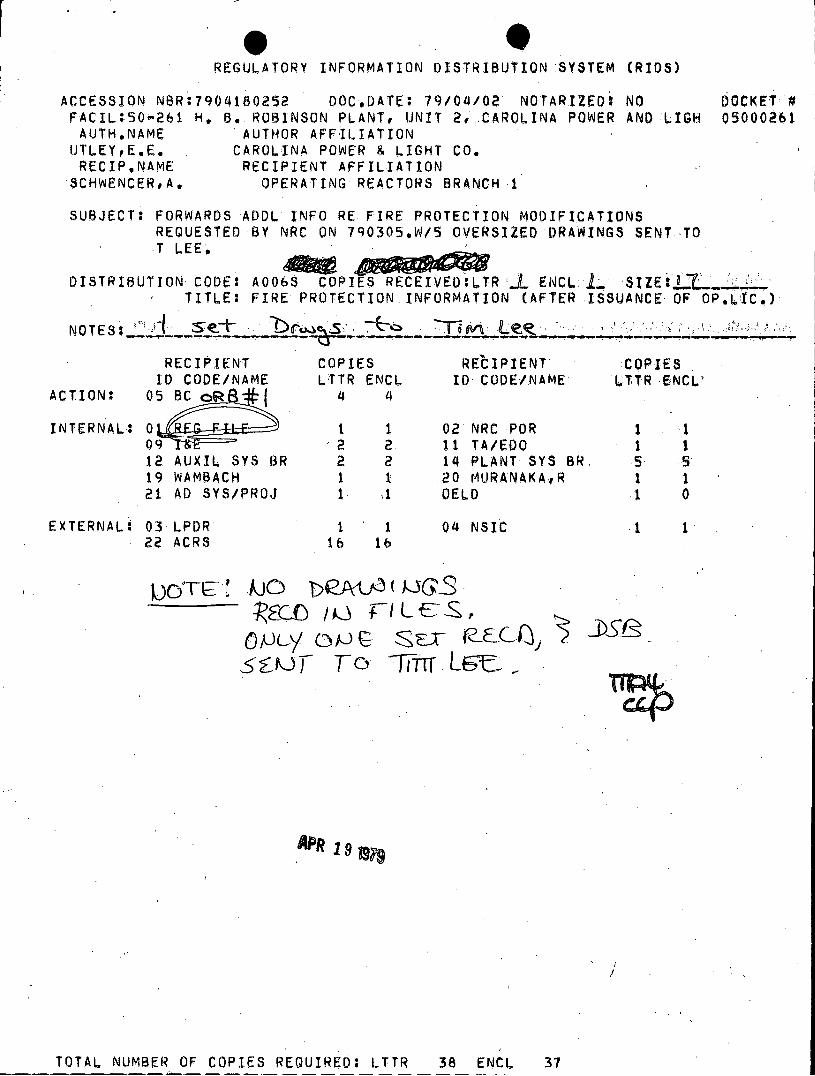
FIRE DETECTION DOCUMENTATION CAROLINA POWER & LIGHT COMPANY
HARTSVILLE, SOUTH CAROLINA
CEILING ACCEPTABLE ACCEPTABLE ACTUAL ACTUAL FIRE ZONE AIR CHANGES HEIGHT & MAX. SQ. FT. MIN. NO. Sq. FT. NO. NO. ROOM SQ. FT. PER HOUR FEET PER DETECTOR DETECTORS PER DETECTOR DETECTORS
1 Diesel 902 4.2 19 Special Gen- 3 NA 3 Gen. B erator Coverage
2 Diesel 902 4.2 19 Special Gen- 3 NA 3 Gen. A erator Coverage
3 SIS 856 7.74 19 740 2 214 4 Pump
4 Charging 845 11.2 19 625 2 211 4 Pump
5 Component 2,340 11.75 15.5 625 4 390 6 Cooling 19
6 Hot Chem. 460 12 15.5 625 2 460 2 & Count 150 15.5 150 Room
7 Aux. FW 208 3.7 15.5 900 1 104 2 Pump
8 Boron 365 2.7 15 900 1 182.5 2 Injection
9 Cable 267 2.5 22.5 900 1 72 4 Vault N
- 10 Cable 676 60 22.5 125 6 113 6 Vault S
11 Corridor 1,024 5.6 19 585 4 256 8 (N)

PAGE 2
CEILING ACCEPTABLE ACCEPTABLE ACTUAL ACTUAL FIRE ZONE AIR CHANGES HEIGHT & MAX. Sq. FT. MIN. NO. SQ. FT. NO. NO. ROOM SQ. FT. PER HOUR FEET PER DETECTOR DETECTORS PER DETECTOR DETECTORS
12 Corridor 1,540 4.2 19 740 4 128 12 (Cent.)
13 Corridor 1,063 11.6 19 625 4 133 8 (S)
14 Solid 1,085 4.9 19 271 4 90 12 Waste
15 Corridor 1,286 5.9 19 257 5 129 10
16 Battery 510 4.5 13 585 2 128 4 Room
17 HVAC 826 6.9 10.5 740 2 207 4Equipment
18 Cable 609 .5.2 10.5. 740 1 304.5 2 Room #1
19 Cable 1,032 32 10.5 180 6 129 8 Room #2
20 Elect. 2,150 8.7 15.2 750 6 60 14 Equip.
21 CRDM 802 14.3 11.5 500 2 267 3
22 Control 1,460 17 12 375 6 146 10 Room
23 Relay 580 21.5 12 300 2 145 4 Room
24 Reactor NA NA NA Local 4 Local 8 Bldg. Application Application Elev. 228'
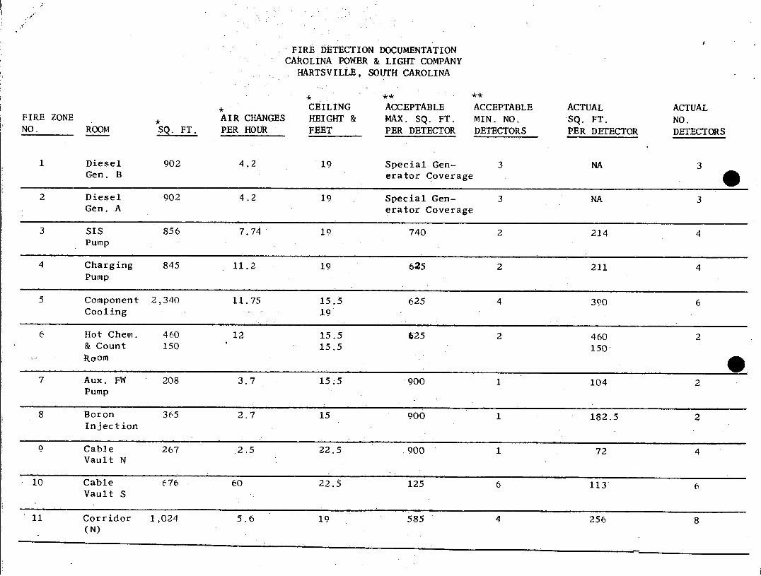
'PAGE 3
CEILING ACCEPTABLE ACCEPTABLE ACTUAL ACTUAL
FIRE ZONE AIR CHANGES HEIGHT & MAX. SQ. FT. MIN. NO. SQ. FT. NO. NO. ROOM SQ. FT. PER HOUR FEET PER DETECTOR DETECTORS PER DETECTOR DETECTORS
25 Reactor NA NA NA Local 3 Local 6 Bldg. Application Application Elev. 251.5'
26 Reactor NA NA NA Local 4 Local 8 Bldg. Application Application Elev. 275'
27 RHR 718 1.49 28 500 2 144 5
28 Pipe 1,696 3.7 19 410 6 242 7
Space
* Information obtained from NUS Task #5137-AC Calculations
** Information obtained from charts and tables in NFPA72E, 1978 Edition including appendix A, manufacturer's
recommendations and engineering judgement as stated in paragraph 4 - 3.1 NFPA72E, 1978.

0 FIRE DETECTION DOCUMENTATION
CAROLINA POWER & LIGHT COMPANY HARTSVILLE, SOUTH CAROLINA
Zone 1 - Diesel Generator B
The UV Detectors are mounted at a height of 10. feet. This is highest
possible height due to pipe obstructions. One detector is mounted on
each side of the DG for optimum protection. Sensitivity is field adjustable
for maximum performance.
Zone 2 - Diesel Generator A
Same as Zone 1,
Zone 3 - SIS Pump
Cable tray exist on both sides. Detectors mounted as close as possible
to cable trays. Beam depth 12". Detector types cross-zoned for maximum
coverage.
Zone 4 - Charging Pump
Beam depth 12". Detector tynes cross-zoned for maximum coverage.
Zone 5 - Component Cooling
Beam depth 12". Detector type cross-zoned for maximum performance.
Zone 6 - Hot Chem. & Count Room
Lay-in ceiling tile. Detectors located using engineering judgement.
Zone 7 - Aux. FW Pump
Same as Zone 6.
Zone 8 - Boron Injection
Beam depth 12". Detectors located using engineering judgement.
Zone Q - Cable Vault N
Beam depth 12". Detector types cross-zoned. Detectors located over cable
trays. Air handler discharge grilles located at 10 ft. level, well below
detector mounting heights.
Zone 10 - Cable Vault S
Detector types cross-zoned. Detectors located over cable trays. Photoelectric
detectors located for optimum back up efficiency. Beam depths 12".

Fire Detection Docum tion Carolina Power & Ligh Company Page 2
Zone 11 - Corridor N
Beam depth 12". Cable trays both sides of hall. Detectors very difficult to locate due to obstructions. Detectors located between both cable trays. Detector types installed alternately.
Zone 12 - Corridor Cent.
Cable trays both sides. Beam depth 12". Large air handler duct located close as possible to cable trays. Bus duct between cable trays and ceiling. Detector types installed alternately.
Zone 13 - Corridor S
Beam depth 12". Detectors located over cable trays or as close as possible. Hall has large duct on side, cable tray on the other. Detectors mounted in 1 ft. space separating the two. Very conjested area.
Zone 14 - Solid Waste
12" beam depth. Detector types installed alternately on the circuits on circuit D. These detectors located in the bays between beams. Detectors on circuit C are installed on the beams for optimum coverage.
Zone 15 - Corridor
Large air handler ducts located on both sides of corridor mounted against the ceiling. Cable trays located on both sides of corridor. Detectors mounted in only area possible without sacrificing engineering judgement. Detectors cross-zoned for optimum coverage.
Zone 16 - Battery Room
Beam depth 12". Detectors cross-zoned for optimum coverage. Detectors primarily located over storage batteries.
Zone 17 - HVAC Equipment
Beam depth 12". Detectors cross-zoned for optimum coverage.
Zone 18 - Cable Room #1
Beam depth 12". Detectors located close to cable trays.
Zone 19 - Cable Room #2
Beam depth 12". Relay racks located on both sides. Detector types cross-zoned for optimum coverage. Detectors primarily located over cable trays.and relay racks.

Fire Detection Documentation Carolina Power & Light Company Page 3
Zone 20 - Electrical Equipment
Beam depth 12". Detector types installed alternately on fire circuit A. B circuit detectors installed cross-zoned with circuit A. Detectors installed primarily over cable trays and motor control centers.
Zone 21 - CRDM
Beam depth 12". Detectors located over cable trays.
Zone 22 - Control Room
Lay-in ceiling tile. Detectors alternately installed on each fire circuit. Each adjacent detector circuit type is alternately installed. Detectors are primarily located over control cabinets.
Zone 23 - Relay Room
Lay-in ceiling tile detector types and circuits are cross-zoned for optimum coverage. Detectors primarily spaced over relay racks.
Zone 24 - Reactor Building - Elev. 228'
Detectors will be mounted to the underside of the catwalk grating with primary coverage over the cable trays. Detectors will be installed alternately by type, on each fire circuit to provide optimum coverage. Adjacent detectors will also be installed alternately.
Zone 25 - Primary Coolant Pumps
Detectors will be installed primarily for the protection of the coolant pumps and detection of fire resulting from spilled oil.
Zone 26 - Containment General Area
Heat Detectors will be mounted under the motor housing. Ionization detectors will be mounted on the underside of the large duct close as possible to charcoal filters in the return air supply.
Fife Detection Documewation
Carolina Power & Light Company
Page 4
Zone 27 - RHR Pump Pit
Detectors installed over RHR pumps. Combustion of oil is primary fire
hazard.
Zone 28 - Pipe Alley
Detectors primarily located in center of hallway. Detector types alternately installed on each circuit. Each circuit alternately
interlaced with each other to provide optimum coverage by detector
type.

Partial Listing of Fire Detection Jobs by Pyrotronics
1. San Onofre Southern California Edison Company
2. Indian Point Consolidated Edison Company of New York, Inc.
3. Pacific Northwest Laboratories - Hanford Richmond, Washington
4. Peach Bottom Philadelphia Electric Co.
5. Enrico Fermi Detroit Edison Co.
6. Connecticut Yankee Connecticut Yankee Atomic Power Co.
7. Shippingport Duquesne Light Co.
8. Hatch Georgia Power Co.
9. Farley Alabama Power Co.
10. Tennessee Valley Authority Plants a) Sequoyah b) Watts Bar c) Bellefonte d) Hartsville e) Phipps Bend
CP&L Response to Staff Concern on SER Item 3.1.17
The following information is provided in response to the concerns in
this area:
a) Regarding the service temperature of the hydrous calcium silicate
material, the vendor, Johns-Manville, has informed CP&L that the
indicated catalog temperature is 1500aF. In exposure situation,
the material will begin to shrink at temperatures in excess of 18000F.
The amount of shrinkage is about 20 percent at a sustained temperature
of 2000*F. The insulation will be applied, in accordance with the
manufacturer's recommendations, in two layers with staggered joints
to overcome the expected shrinkage. The thickness of the outer layer
is two inches, while the thickness of the inner layer is one inch. In
addition, an 18 gauge stainless steel jacket capable of 2800*F exposure
has been specified for the outside wrapping.
According to Mr. W. H. Doyle, damage (shrinkage) of the insulation at
high temperatures involves endothermic loss of bound water of hydration.
This results in the residue being a better barrier to heat transmission
than in its original state and thus, more effective under fire situations.
b) Heat transfer for the fuel oil line was neglected because the oil would
not be pumped into the room with the fire, therefore, there would not
be a flow of oil to remove heat and protect the fuel oil line from
achieving its flash point temperature. The effect of heat transfer
was included in calculating the insulation thickness for the service
water lines because there would be a known flow through the water lines
while a fire was in progress in Diesel Generator Room "A".
c) The effect of using the standard time-temperature curve, rather than
the true one, is to heighten the amount of heat transferred to the
insulated pipe. In a ventilation limited fire, such as the one postula
ted here would be, the temperature would be below that of the standard
time-temperature curve. The reference for this statement is, "Design
of Buildings for Fire Safety," by T. Z. Harmathy, Fire Research Section,
National Research Council of Canada, in "Fire Technology" Volume 12,
No. 2. May 1976.

2
As a result, CP&L believes that the intended installation of insulation
on the service water lines and oil lines in the Diesel Generator area is conserva
tive and fully adequate to provide the desired degree of protection.
CP&L Response to'Staff Concern on SER Item 3.1.21
Information on sizing of oil lines, drip pans, and other components
to accommodate the. maximum credible flow rate of oil from .a spill, leak, or
other failure in the lubrication oil system has not yet been received from the
oil collection system designer. As has been discussed with your staff, CP&L
intends to defer the installation of this system to allow further study of
alternate means of controlling and suppressing a postulated reactor coolant
pump oil fire. This will be addressed and justified in more detail in a sub
sequent submittal. If, after the studies.are completed, it is intended to
continue with installation of an oil collection system, the sizing information
will be forwarded to you at that time for your review.

CP&L Response to Staff Concern on SER Item 3.1.24
One of the outstanding concerns following the telephone conversation
with the Staff and its consultant on March 5, 1979, was the lack of data con
cerning a hose stream test for the H. B. Robinson cable tray penetration tested
by Gold Bond Laboratories and reported in our letter of September 1, 1978.
In a report entitled "Report on Fire Stop Tests for Rancho Seco Nuclear
Generation Station - Unit No. 1, February 24, 1978," the Sacramento Municipal
Utility District performed fire stop qualification testing, including hose stream
testing, on a three-hour fire barrier for cable tray penetrations similar to the
Robinson barrier. The information may be found in Section IV of the report,
which is on file with the Nuclear Regulatory Commission.
The differences between the Robinson barrier design and the Rancho Seco
barrier design are as follows:
1. The Robinson barrier employs two layers of 1/2" maunite XL board instead of
one layer as in the Rancho Seco barrier.
2. The Robinson barrier has a coating of 1/4" dry thickness of Flamemastic 77
instead of 1/8" dry thickness of Flamemastic 71A as in the Rancho Seco
barrier.
3. The Robinson barrier has an internal filling of Kaowool Bulk Fiber instead
of Flamemastic 71A as in the Rancho Seco barrier.
Except for the internal fill material of the barrier, the Robinson design
is much more conservative than the Rancho Seco design, which successfully passed the
hose stream test. As a result, CP&L believes that the Robinson design would have
successfully passed the hose stream test and is suitable for use as a fire barrier
in the plant.