DOT MATRIX PRINTER MODEL CBM-910 - CITIZEN SYSTEMS · CBM-910 User’s Manual CITIZEN 3 2.3...
48
DOT MATRIX PRINTER MODEL CBM-910
Transcript of DOT MATRIX PRINTER MODEL CBM-910 - CITIZEN SYSTEMS · CBM-910 User’s Manual CITIZEN 3 2.3...
DOT MATRIX PRINTERMODEL CBM-910

CBM-910 User’s Manual
CITIZEN
Declaration of Conformity Manufacturer's Name : Japan CBM Corporation Manufacturer's Address : CBM Bldg.,5-68-10, Nakano, Nakano-ku, Tokyo 164-0001, Japan Declare the Product Product Name : Dot Matrix Printer Model Number (s) : CBM-910 Series (CBM-910R, CBM-910P) (S.NO.0090001 - ) Conform to the following Standards LVD : EN60950 :A4:1997 EMC : EN55022 :1998 Class A EN61000-3-2 :1995+A1:1998+A2:1998 EN61000-3-3 :1995 EN55024 :1998 EN61000-4-2 :1995 ±4KV CD, ±8KV AD EN61000-4-3
EN61000-4-4 EN61000-4-5 EN61000-4-6 EN61000-4-8 EN61000-4-11
:1996 3V/m, 80MH-1000MHz AM 1KHz 80% :1995 ±1.0KV (AC Mains), ±0.5KV (Signal Lines) :1995 ±1KV (Normal mode), ±2KV (Cmmon mode) :1996 3V, 0.15MHz-80MHz AM 1KHz 80% :1993 50Hz, 1A/m :1994 0%, 5000ms/ 70%, 500ms/ 0%, 10ms
Supplementary Information "The product complies with the requirements of the Low Voltage Directive 73/23/EEC, 93/68/EEC and the EMC Directive 89/336/EEC, 92/31/EEC, 93/68/EEC"
Place : Tokyo, Japan Date :
September,2000 Signature:
Full Name : Mikio Moriya Position : General Manager R & D Department Europe Contact : Norco Declaration AB Box 7146 S-250 07 Helsingborg, Sweden
This declaration is applied only for 230V model.
CBM-910 User’s Manual
CITIZEN
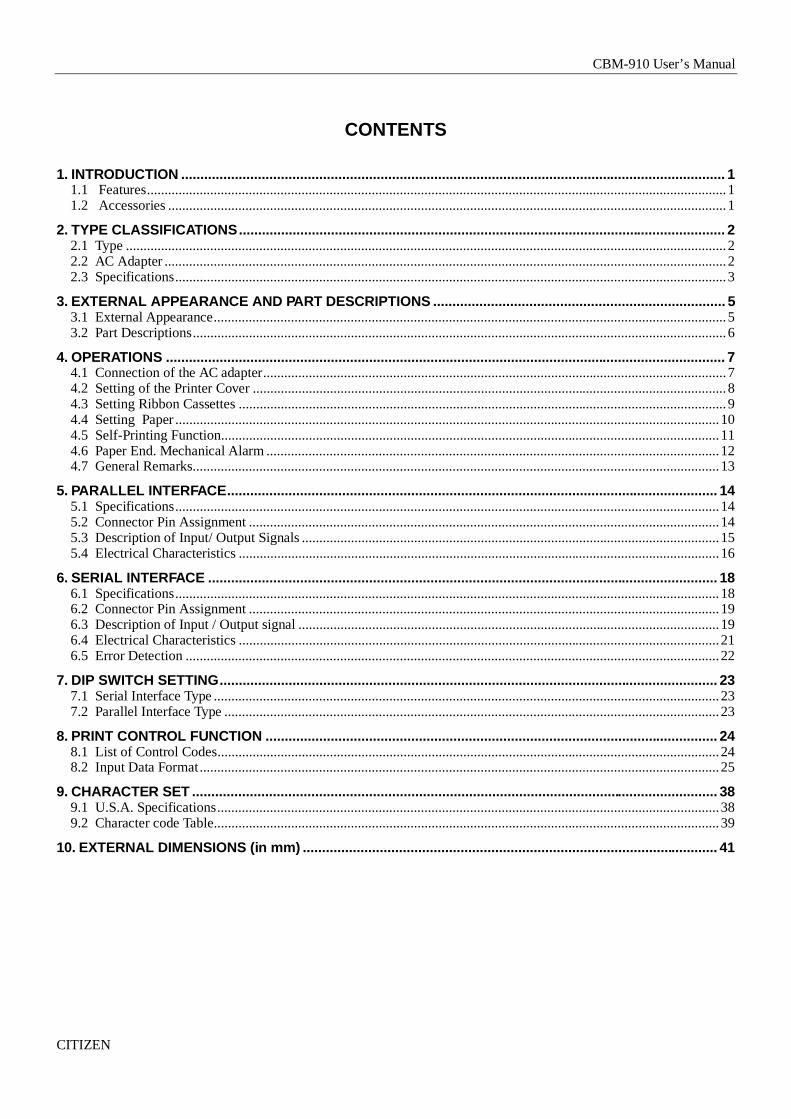
IMPORTANT SAFETY INSTRUCTIONS
* Read all of these instructions and save them for later reference.* Follow all warnings and instructions marked on the product.* Unplug this product from the wall outlet before cleaning. Do not use liquid or aerosol cleaners. Use a damp cloth for
cleaning.* Do not use this product near water.* Do not place this product on an unstable cart, stand of table. The product may fall, causing serious damage to the
product.* Slots and openings on the cabinet and the back or bottom are provided for ventilation.
To ensure reliable operation of the product and to protect it from overheating, do not block or cover these openings.The openings should never be blocked by placing the product on a bed, sofa, rug of other similar surface.This product should never be placed near or over a radiator or heat register.This product should not be placed in a built-in installation unless proper ventilation is provided.
* This product should be operated from the type of power source indicated on the marking label.If you’re not sure of the type of power available, consult your dealer or local power company.
* Do not allow anything to rest on the power cord. Do not locate this product where the cord will be walked on.* In an extension cord is used with this product, make sure that the total of the ampere ratings on the products plugged
into the extension cord do not exceed the extension cord ampere rating.Also, make sure that the total of all products plugged into the wall outlet dose not exceed 15 amperes.
* Never push objects of any kind into this product through cabinet slots as they may touch dangerous voltage points orshort out parts that could result in a risk of fire or electric shock. Never spill liquid of any kind on the product.
* Except as explained elsewhere in this manual, don’t attempt to service this product by yourself.Opening and removing those covers that are marked “Do Not Remove” may expose you to dangerous voltage pointsor other risks. Refer all servicing on those compartments to service personnel.
* Unplug this product from the wall outlet and refer servicing to qualified service personnel under the followingconditions:
A. When the power cord or plug is damaged or frayed.B. If liquid has been spilled into the product.C. If the product has been exposed to rain or water.D. If the product dose not operate normally when the operating instructions are followed. Adjust only those
controls that are covered by the operating instructions since improper adjustment of other controls mayresult in damage and will often require extensive work by a qualified technician to restore the product tonormal operation.
E. If the product has been dropped the cabinet has been damaged.F. If the product exhibits a distinct change in performance, indicating a need for service.

CBM-910 User’s Manual
CITIZEN
IMPORTANT:This equipment generates, uses, and can radiate radio frequency energy and if not installed and used inaccordance with the instruction manual, may cause interference to radio communications. It has been tested andfound to comply with the limits for a Class A computing device pursuant to Subpart J of Part 15 of FCC Rules,which are designed to provide reasonable protection against such interference when operated in a commercialenvironment. Operation of this equipment in a residential area is likely to cause interference, in which case theuser at his own expense will be required to take whatever measures may be necessary to correct the interference.
CAUTION: Use shielded cable for this equipment.
SicherheitshinweisDie Steckdose zum Anschluß dieses Druckers muß nahe dem Gerät angebracht und leicht zugänglich sein.
For Uses in CanadaThis digital apparatus does not exceed the class A limits for radio noise emissions from apparatus, as set out inthe radio interference regulations of the canadian department of communications.
Pour L’utilisateurs CanadiensCet appareil numérique ne dépasse pas limites de carégorie a pour les émissions de bruit radio émanantd’appareils numériques, tel que prévu dand les réglements sur l’ interference radio du départment canadien descommunications.
CBM-910 User’s Manual
CITIZEN
CONTENTS
1. INTRODUCTION .............................................................................................................................................. 11.1 Features.....................................................................................................................................................................11.2 Accessories ...............................................................................................................................................................1
2. TYPE CLASSIFICATIONS........................................................................................................ ....................... 22.1 Type ...........................................................................................................................................................................22.2 AC Adapter ................................................................................................................................................................22.3 Specifications.............................................................................................................................................................3
3. EXTERNAL A PPEARANCE AND PART DESCRIPTIONS ............................................................................ 53.1 External Appearance..................................................................................................................................................53.2 Part Descriptions........................................................................................................................................................6
4. OPERATIONS .................................................................................................................................................. 74.1 Connection of the AC adapter....................................................................................................................................74.2 Setting of the Printer Cover .......................................................................................................................................84.3 Setting Ribbon Cassettes ...........................................................................................................................................94.4 Setting Paper ...........................................................................................................................................................104.5 Self-Printing Function..............................................................................................................................................114.6 Paper End. Mechanical Alarm .................................................................................................................................124.7 General Remarks......................................................................................................................................................13
5. PARALLEL INTERFACE.......................................................................................................... ...................... 145.1 Specifications...........................................................................................................................................................145.2 Connector Pin Assignment ......................................................................................................................................145.3 Description of Input/ Output Signals .......................................................................................................................155.4 Electrical Characteristics .........................................................................................................................................16
6. SERIAL INTERFACE ............................................................................................................ ......................... 186.1 Specifications...........................................................................................................................................................186.2 Connector Pin Assignment ......................................................................................................................................196.3 Description of Input / Output signal ........................................................................................................................196.4 Electrical Characteristics .........................................................................................................................................216.5 Error Detection ........................................................................................................................................................22
7. DIP SWITCH SETTING.................................................................................................................................. 237.1 Serial Interface Type ................................................................................................................................................237.2 Parallel Interface Type .............................................................................................................................................23
8. PRINT CONTROL FUNCTION ...................................................................................................................... 248.1 List of Control Codes...............................................................................................................................................248.2 Input Data Format....................................................................................................................................................25
9. CHARACTER SET ......................................................................................................................................... 389.1 U.S.A. Specifications...............................................................................................................................................389.2 Character code Table................................................................................................................................................39
10. EXTERNAL DIMENSIONS (in mm) ................................................................................................ ............ 41

CBM-910 User’s Manual
CITIZEN 1
1. INTRODUCTION
The CBM-910 is a dot-impact printer widely usable with various data communication terminals and measurementterminals.This printer, being extremely compact and equipped with extensive functions, is suitable to a wide range of applications.You are kindly requested to read this manual thoroughly to understand the product prior to actual use.
1.1 Features
1. Compact desk-top dot matrix printer2. Light weight3. High speed printing4. Paper-end detecting function5. Conformity to RS-232C and Centronics.6. Low power consumption7. Low price
1.2 Accessories
The following attachments are included in this set aside from the printer itself. Please confirm.
Paper roll (1 roll)Ribbon cassette (1unit)AC adapter (1 unit)User’s manual (1 booklet)

CBM-910 User’s Manual
CITIZEN 2
2. TYPE CLASSIFICATIONS
2.1 Type
The product is categorized according to the naming plan indicated below.
CBM-910 24
40
P
R
F 230 A
CBM-910 - 24 R F 230 - A Model Name Printer cover Number of columns *1 A : 60mm(Dia.) 24 : 24 columns/144 dots(MD-910) Paper roll 40 : 40 columns/180 dots(MD-911) B : 80mm(Dia.) Paper roll Adapter 120 : AC 120V 230 : AC 230V
Interface P : Parallel(centronics) R : Serial(RS-232C) Character
F : International (Note) *1) No. of digits varies for ROM.
2.2 AC Adapter
Please use the exclusive adapter indicated below. 91AD-U (AC 120V) 91AD-E (AC 230V)

CBM-910 User’s Manual
CITIZEN 3
2.3 Specifications
Item CBM-910-24* CBM-910-40*1 Printing method Dot matrix2 Printing direction One-way printing3 Character configuration
(W × H) (5 + 1) × 8 (4 + 0.5) × 84 Number of columns per line 24 columns: 144 dot/line 40 columns: 180 dot/line5 Printing speed Approx. 2.5 line/sec. Approx. 1.8 lines/sec.6 Character size (W × H) 1.62 × 2.4 mm 1.08 × 2.4 mm7 Line pitch 3.52 mm8 Paper Paper Roll 57.5 ± 0.5(W) × 60 or 80 (Dia) mm
Core ID φ 12 ± 1 mm Core OD φ 18 ± 1mm *19 Interface Parallel Interface (Conformity to Centronics) or
Serial Interface (RS-232C)10 Input buffer 2K bytes11 Paper-end detection Printing suspended when printing paper gets scarce.12 Ink ribbon Purple (Private ribbon cassette)
Service life: approx. 250,000 letters13 Voltage DC 7V ± 1V (Printing)
Use exclusive adapter (DC 7V, 1.6A)14 Power consumption Printing : approx. 7VA
Stand-by : approx. 0.5VA15 Weight Approx. 400g16 Reliability MCBF 1 million lines MCBF 700,000 lines17 Dimension 106(W) × 180(D) × 88(H) mm18 Operating temp. 0°C to 40°C19 Storage temp -20°C to 60°C
CBM-910 User’s Manual
CITIZEN 4
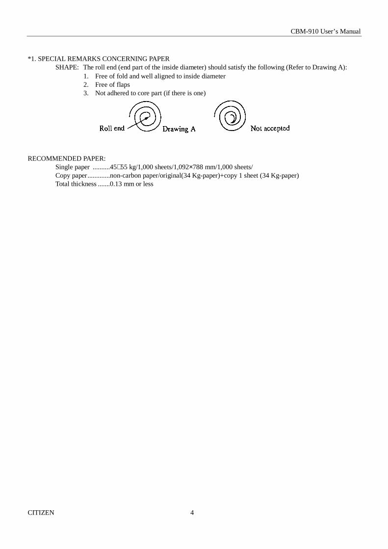
*1. SPECIAL REMARKS CONCERNING PAPERSHAPE: The roll end (end part of the inside diameter) should satisfy the following (Refer to Drawing A):
1. Free of fold and well aligned to inside diameter2. Free of flaps3. Not adhered to core part (if there is one)
RECOMMENDED PAPER:Single paper ..........45∼55 kg/1,000 sheets/1,092×788 mm/1,000 sheets/Copy paper.............non-carbon paper/original(34 Kg-paper)+copy 1 sheet (34 Kg-paper)Total thickness .......0.13 mm or less
CBM-910 User’s Manual
CITIZEN 5
3. EXTERNAL APPEARANCE AND PART DESCRIPTIONS
3.1 External Appearance
CBM-910 User’s Manual
CITIZEN 6
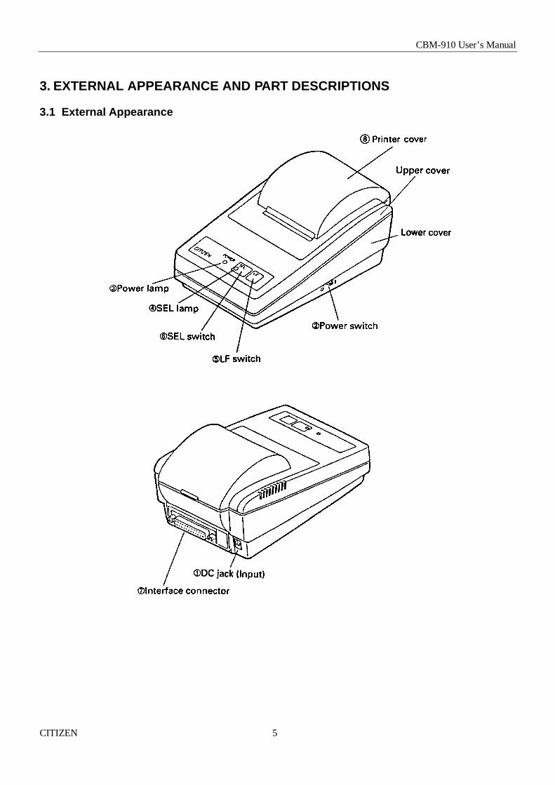
3.2 Part Descriptions
1. DC Jack Insert the output plug of the AC adapter attached.2. Power Switch When switched ON, power is supplied to the Printer, starting the initializing operation.
3. Power Lamp Lighted when power is turned ON and goes out when turned OFF.
4. SEL Lamp Printer lights up in Select (ON LINE) state, and is put off in Deselect (OFF LINE) state.Printing operation is available only while this lamp is lit.1) It blinks, for paper end, at 0.5 second intervals. Change paper.2) On occurrence of any alarm state (blinking) due to any reason other than paper end, it
starts to blink at 1/4 second intervals.Eliminate the cause and either press SEL switch or cut off power for the printer forresumption.
5. LF Switch Paper is fed when switch is pressed (de-select condition only). Used to supply paper or to insert some space in the output.
6. SEL Switch Printer is selected (ON-LINE) by pressing this switch.Printer is de-selected (OFF-LINE) by pressing the switch again.Also used to release alarm state. In Deselect state, if data still remain in the input buffer,they are all printed out.
7. Interface Connector Printer is connected to various hosts via cables. Please ensure that both the printer andthe host are turned off before connecting.
8. Printer Cover Opened to exchange ribbon cassette and paper roll.
CBM-910 User’s Manual
CITIZEN 7
4. OPERATIONS
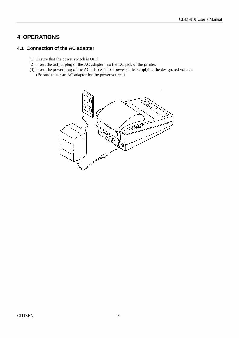
4.1 Connection of the AC adapter
(1) Ensure that the power switch is OFF.(2) Insert the output plug of the AC adapter into the DC jack of the printer.(3) Insert the power plug of the AC adapter into a power outlet supplying the designated voltage.
(Be sure to use an AC adapter for the power source.)

CBM-910 User’s Manual
CITIZEN 8
4.2 Setting of the Printer Cover
(1) Hold the protruding section at the rear of the printer cover and lift in the direction indicated.(2) Attach the cover by pressing downward after hooking the cover to the acceptor located in the front part.

CBM-910 User’s Manual
CITIZEN 9
4.3 Setting Ribbon Cassettes
(1) Remove the printer cover turning OFF the printer.(2) Press down on the Ribbon cassette while inserting the ribbon between the printing head and the platen.(3) Wind up the ribbon slack by turning the knob in the direction of the arrow.
CBM-910 User’s Manual
CITIZEN 10
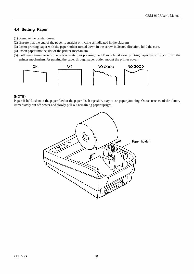
4.4 Setting Paper
(1) Remove the printer cover.(2) Ensure that the end of the paper is straight or incline as indicated in the diagram.(3) Insert printing paper with the paper holder turned down in the arrow-indicated direction, hold the core.(4) Insert paper into the slot of the printer mechanism.(5) Following turning-on of the power switch, as pressing the LF switch, take out printing paper by 5 to 6 cm from the
printer mechanism. As passing the paper through paper outlet, mount the printer cover.
(NOTE)Paper, if held aslant at the paper feed or the paper discharge side, may cause paper jamming. On occurrence of the above,immediately cut off power and slowly pull out remaining paper upright.

CBM-910 User’s Manual
CITIZEN 11
4.5 Self-Printing Function
(1) Test printingWith power supplied as LF switch being press down, all characters available for use are printed out.SEL lamp is held off during this stage, where BUSY signal is output.On completion of test printing, normal operation is recovered.
(2) Dip switch information printingWith power supplied as LF/SEL switch is pressed, the dip switch/communication method (including set details forserial) are printed.At this point, SEL lamp is held off where BUSY signals are output.Only with a 40-column type printer, following printing of dip switch information, printing is available in on-linein hexadecimal dump mode.
(3) Hexadecimal dump modeAll data sent from the host computer are printed in hexadecimal codes.When data for the last line are not sufficient for full one line, data of the last line are printed out with SEL switchbeing pressed and deselected (OFF LINE).This mode lasts till power is cut off.
Example of Printing in Dump Mode

CBM-910 User’s Manual
CITIZEN 12
4.6 Paper End. Mechanical Alarm
(1) Paper endPrinting paper shortage is detected and informed with SEL lamp blinking at 0.5 second intervals, where printing issuspended. At this time, power supply to the motor and printing solenoid is stopped with BUSY signals output in thehost computer.To recover from Paper End state, set new paper and press SEL switch twice. LF functions normally.By pressing SEL switch twice, you can print, without changing paper, data for one-line input buffer on the remainingpage.
(2) Mechanical alarmOn occurrence of locked motor, any kind of trouble in the mechanism is suspected. Power supply to the motor andprinting solenoid is stopped and BUSY signals are output in the host computer. SEL lamp is then blinked at 1/4second intervals. To recover from alarm state, eliminate the trouble cause and press SEL switch twice.If it is in the course of printing, printing is started at the beginning of the interrupted line. (Content of the input bufferis still held.) However, this dose not apply to a case where power has been cut due to a severe trouble.

CBM-910 User’s Manual
CITIZEN 13
4.7 General Remarks
(1) Do not print without ink ribbon properly provided. It may cause damage on the print head.(2) Change ink ribbon before it becomes worn-out. Do not supplement ink.(3) Be careful not to drop, inside the main body, a clip, a setting pin, or any foreign matter. It will lead to machine
failure.(4) To operate the printer, hold it on a flat stable table. If it not being flat or stable, the main body will be displaced by
vibrations while in printing, creating possible danger. Fixing it steadily is also important to avoid erroneousoperation.
(5) To clean the surface of the printer main body, never use organic solvent (alcohol / thinner / benzine, etc.)(6) Paper, if left for long hours with a ribbon cassette mounted. Also, continuous printing, if conducted at a low
temperature, may cause thin printing due to ink features.(7) Ribbon cassette, upon shipment, should not be mounted on a printer

CBM-910 User’s Manual
CITIZEN 14
5. PARALLEL INTERFACE
5.1 Specifications
(1) Data input system : 8 bit parallel (DATA 1-8)(2) Control signal : ACK, STB, BUSY, RESET,(3) Compatible Connector : Printer side : 57LE-40360 (AMPHENOL or equivalent)
Cable side : 57-30360 (AMPHENOL or equivalent)
5.2 Connector Pin Assignment
PIN SIGNAL NAME PIN SIGNAL NAME1 STB 19 TWISTED PAIR GND2 DATA 1 20 TWISTED PAIR GND3 DATA 2 21 TWISTED PAIR GND4 DATA 3 22 TWISTED PAIR GND5 DATA 4 23 TWISTED PAIR GND6 DATA 5 24 TWISTED PAIR GND7 DATA 6 25 TWISTED PAIR GND8 DATA 7 26 TWISTED PAIR GND9 DATA 8 27 TWISTED PAIR GND10 ACK 28 TWISTED PAIR GND11 BUSY 29 TWISTED PAIR GND12 GND 30 TWISTED PAIR GND13 HI-LEVEL 31 RESET14 GND 3215 33 GND16 GND 3417 FRAME GND 3518 36

CBM-910 User’s Manual
CITIZEN 15
5.3 Description of Input/ Output Signals
(1) Input signal* DATA 1………..8 bit parallel signal (positive logic)* DATA 2………..8 bit parallel signal (positive logic)* DATA 3………..8 bit parallel signal (positive logic)* DATA 4………..8 bit parallel signal (positive logic)* DATA 5………..8 bit parallel signal (positive logic)* DATA 6………..8 bit parallel signal (positive logic)* DATA 7………..8 bit parallel signal (positive logic)* DATA 8………..8 bit parallel signal (positive logic)* STB……………Strobe signal for reading out data (negative logic)* RESET………...Signal for resetting the entire unit (negative logic 4ms or more)
(2) Output signal
* ACK…………..8 bit data signal for requesting data. ACK is issued at the end of the BUSY signal (negative logic)* BUSY…………Signal indicating the printer is busy. Input new data when the signal is in “LOW” condition.
(positive logic)* HI-LEVEL……Connected to Vcc via 3.3 kΩ resistance.
(3) Timing chart
T1 2.7µs MINT2 500mS MIN (When power is supplied)T3 10µs TYP
CBM-910 User’s Manual
CITIZEN 16
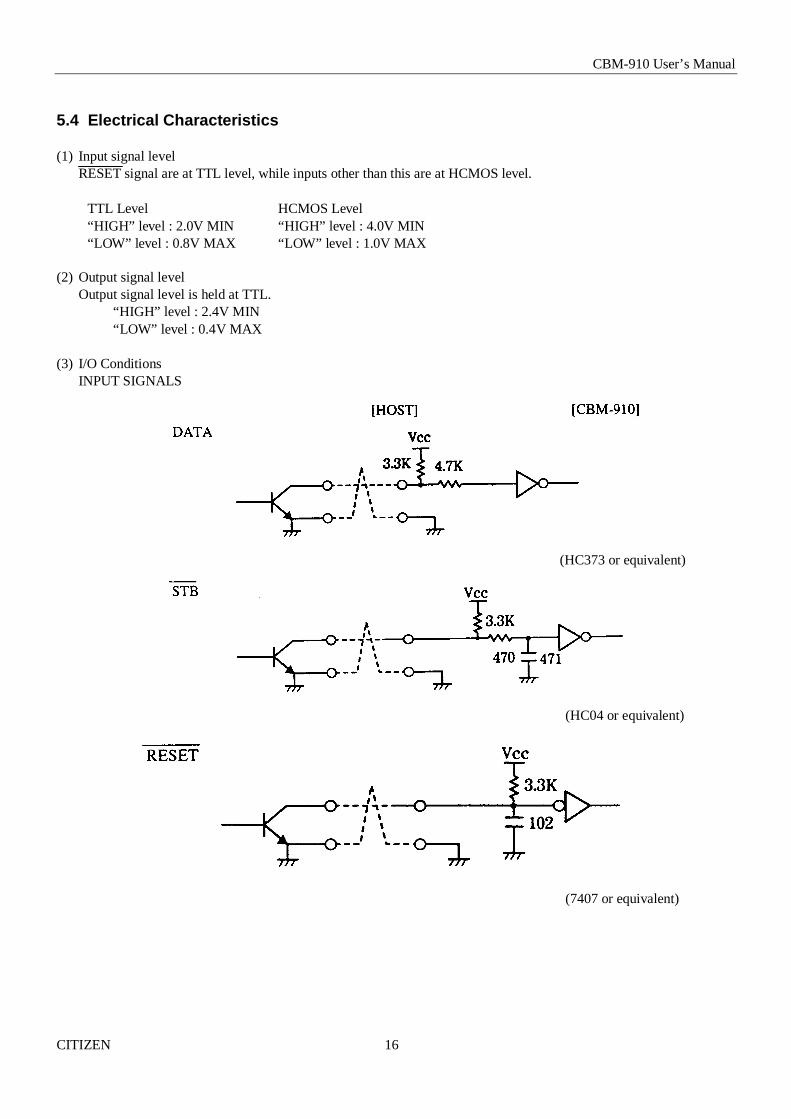
5.4 Electrical Characteristics
(1) Input signal levelRESET signal are at TTL level, while inputs other than this are at HCMOS level.
TTL Level HCMOS Level“HIGH” level : 2.0V MIN “HIGH” level : 4.0V MIN“LOW” level : 0.8V MAX “LOW” level : 1.0V MAX
(2) Output signal levelOutput signal level is held at TTL.
“HIGH” level : 2.4V MIN“LOW” level : 0.4V MAX
(3) I/O ConditionsINPUT SIGNALS
(HC373 or equivalent)
(HC04 or equivalent)
(7407 or equivalent)

CBM-910 User’s Manual
CITIZEN 17
OUTPUT SIGNAL
ACKBUSY
(7407 or equivalent)
CBM-910 User’s Manual
CITIZEN 18
6. SERIAL INTERFACE
6.1 Specifications
(1) Synchronization : Asynchronous(2) Baud rate : 1200, 2400, 4800, 9600 Baud/sec (User selection)(3) Word configuration
•Start bit : 1 bit•Data bit : 7 bit or 8 bit (User selection)•Parity bit : odd, even, no parity (User selection)•Stop bit : 1 bit or more
(4) Signal polarityRS-232C* Mark = Logic”1”(-3 to –12V)* Space = Logic “0”(+3 to +12V)TTL (RESET)* H level = Logic”1”* L level = Logic”0”
(5) Receive Data (RD)* Mark : 1* Space : 0
(6) Transmit Data (TD)* Mark : 1* Space : 0
(7) Received control (DTR signal)* Mark : Data transmission not possible* Space : Data transmission possible
CBM-910 User’s Manual
CITIZEN 19
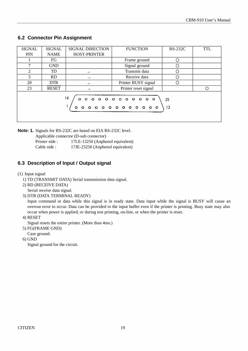
6.2 Connector Pin Assignment
SIGNAL SIGNAL SIGNAL DIRECTION FUNCTION RS-232C TTLPIN NAME HOST-PRINTER1 FG Frame ground7 GND Signal ground2 TD ← Transmit data3 RD → Receive data20 DTR ← Printer BUSY signal23 RESET → Printer reset signal
Note: 1. Signals for RS-232C are based on EIA RS-232C level.Applicable connector (D-sub connector)Printer side : 17LE-13250 (Anphenol equivalent)Cable side : 17JE-23250 (Anphenol equivalent)
6.3 Description of Input / Output signal
(1) Input signal1) TD (TRANSMIT DATA) Serial transmission data signal.2) RD (RECEIVE DATA)
Serial receive data signal.3) DTR (DATA TERMINAL READY)
Input command or data while this signal is in ready state. Data input while the signal is BUSY will cause anoverrun error to occur. Data can be provided to the input buffer even if the printer is printing. Busy state may alsooccur when power is applied, or during test printing, on-line, or when the printer is reset.
4) RESETSignal resets the entire printer. (More than 4ms.)
5) FG(FRAME GND)Case ground.
6) GNDSignal ground for the circuit.

CBM-910 User’s Manual
CITIZEN 20
(2) Data configuration
(1) Start bit (1 bit)(2) Data bit (7 or 8 bit)(3) Stop bit (more than 1)

CBM-910 User’s Manual
CITIZEN 21
6.4 Electrical Characteristics
(1) RS-232C I/O Signals (RD / TD / DTR)∗Input (RD / TD) Mark = (-8V): stop bit
Space = (+8V): start bit∗Output (DTR) Mark = (-8V): for Busy
Space = (+8V): for Ready
(2) TTL CircuitInput (RESET)
[HOST] [CBM-910]
Set to low when reset [HC04 or equivalent]

CBM-910 User’s Manual
CITIZEN 22
6.5 Error Detection
* Communication error
Parity ErrorWhen parity nonconformity heaving been detected out of odd-even parity checking conductedwhen parity check is assigned.
Framing ErrorWhen space state detected on detection of stop bit.
Overrun ErrorWhen next following data having been transferred to receiving buffer register regardless of presence of data inthat receiving buffer register.
On occurrence of the above error, convert data at the time of occurrence into ‘’ (7FH) to print it out.
RECEIVING CONTROL AND BUFFERINGThe CBM-910 controls, on receipt of print data, receiving (DTR Control) in one-word unit.If the host disregards DTR and carries out data transmission at this time. over-run of receiving data may be resulted.This state should be avoided on the host’s responsibility. (The data discharging type host cannot follow this.)This is applicable when the host adopts a double buffer type transmitter.

CBM-910 User’s Manual
CITIZEN 23
7. DIP SWITCH SETTING
7.1 Serial Interface Type
SwitchNo.
Function OFF ON ShippingSetting
1 Character International - OFF2 CR CR disregarded CR + LF OFF3 Bit Length 8 bits 7 bits OFF4 Parity Provided Not provided ON5 Conditions Odd Even OFF
Baud Rate (bps) Selection
SwitchNo.
1200 2400 4800 9600
6 OFF ON OFF ON7 OFF OFF ON ON
*Factory setting is 4800 bps.
7.2 Parallel Interface Type
SwitchNo.
Function OFF ON ShippingSetting
1 Character International - OFF2 CR CR disregarded CR + LF OFF

CBM-910 User’s Manual
CITIZEN 24
8. PRINT CONTROL FUNCTION
8.1 List of Control Codes
Symbol Code (Hexadecimal) FunctionLF 0A Line feed performed after printing.CR 0D Line feed performed after printing.SI 0F Standard letters assigned.SO 0E Laterally enlarged letters assigned.US 1F Standard letters assigned.RS 1E Laterally enlarged letters assigned.
CAN 18 Data cancelled.DC2 12 Inverted prints assigned.DC1 11 Initial setting.
ESC + "B" 1B/42 Continuous paper feed assigned.ESC + "R" 1B/52 International characters to be set.ESC + "/" 1B/2F Sentences registered.ESC + "!" 1B/21 Registered sentences printed.ESC + "&" 1B/26 Individual patterns registered.ESC + "%" 1B/25 Validity of registered letters.ESC + "K" 1B/4B Bit image printing.
FS + "W" + 1 1C/57/1 × 4 enlarged letters assigned.FS + "W" + 0 1C/57/0 × 4 enlarged letters cancelled.

CBM-910 User’s Manual
CITIZEN 25
8.2 Input Data Format
(1) Command for line feed after printing (CR / LF)With CR (0DH)/ LF (0AH) codes input, data in the print buffer are printed. Without data in the print buffer,only line feed is performed. This command is disregarded when the buffer is full. CR can be disregarded withthe DIP SW.
EX) 24-Column Model:[Receiving data]
1 2 3 4 5 6 7 8 9 0 1 2 3 4 5 6 7 8 9 0 1 2 3 4 5 6 7 8 9 0 CR LF
1 2 3 4 5 6 7 8 9 0 1 2 3 4 5 6 7 8 9 0 1 2 3 4 5 6 7 8 9 0 CR LF CR
1 2 3 4 5 6 7 8 9 0 1 2 3 4 5 6 7 8 9 0 1 2 3 4 5 6 7 8 9 0 CR LF CR LF
<Result of printing>1. Dip Switch Setting at CR = CR+LF
1 2 3 4 5 6 7 8 9 0 1 2 3 4 5 6 7 8 9 0 1 2 3 4
S P A C E
1 2 3 4 5 6 7 8 9 0 1 2 3 4 5 6 7 8 9 0 1 2 3 4
S P A C E
S P A C E1 2 3 4 5 6 7 8 9 0 1 2 3 4 5 6 7 8 9 0 1 2 3 4
S P A C E
S P A C E
S P A C E
Head stop position
2. Dip Switch Setting at CR = disregarded
1 2 3 4 5 6 7 8 9 0 1 2 3 4 5 6 7 8 9 0 1 2 3 41 2 3 4 5 6 7 8 9 0 1 2 3 4 5 6 7 8 9 0 1 2 3 41 2 3 4 5 6 7 8 9 0 1 2 3 4 5 6 7 8 9 0 1 2 3 4
S P A C E
Head stop position

CBM-910 User’s Manual
CITIZEN 26
(2) SI / SO and US / RS CommandsSI / SO codes function in the same manner as US / RS as long as 8-bit data are assigned (serial communication databit length), which, however, are divided, under 7-bit assignment, into SI (20H~7FH characters) print assignment andSO (A0H~FFH characters) print assignment functions.
1. Standard letter assignment (SI / US) command:With SI (0FH)/ US (1FH) codes input, lateral enlargement is cancelled and the data following are printed in standardletters.This command can cancel only lateral enlargement, which dose not apply to x 4 enlargement.
2. Laterally enlarged letter assignment (SO / RS) command:With SO (0EH)/RS (1EH) codes input in any columns, the data following are printed in prints enlarged double inwidth. With line feeding or SI / SR code input, this command is cancelled.Although standard and enlarged letters can be mixed within one line, automatic (buffer-full) printing takes placewhen the number of columns reaches 24 (or 40) counted in standard letters.
[Receiving Data]
SO 1 2 3 4 5 6 7 8 6 0 CR
SO 123 SI ABCD CR
SO 123 SI ABC SO 12 CR
A SI 1 2 3 4 5 6 7 8 9 0 1 B
[Results of Printing]
1 2 3 4 5 6 7 8 9 01 2 3ABCD
1 2 3ABC1 2 Mixed printing
A1 2 3 4 5 6 7 8 9 0 1B
Although the last letter has been assigned to lateral enlargement,it is printed in standard letter as it is in 24th columns. (For 40-column mechanism this applied to 40th columns.)

CBM-910 User’s Manual
CITIZEN 27
(3) Data Cancel (CAN) CommandWith CAN (18H) code input, print data held within the line before input of the CAN code are all cancelled.
[Receiving Data]
SO 123456 CAN ABC CR
[Results of Printing] A B C * As data “1 2 3 4 5 6” are cancelled without the command “SO” cancelled, “ABC” is printed in
lateral enlargement.
(4) Inverted Letter Assignment (DC2) CommandWhen data are input with DC2 (12H) attached at the beginning of a line (invalid when attached to any other place),data following are all printed in inverted letters.To cancel this, input either DC2 again or DC1 (initial setting.)
(5) Initial Setting (DC1) CommandWith DC1 (11H) input, various conditions set after power supply are cancelled and the state as at supply of power isrestored. Content of the input buffer, however, is held unchanged.
(6) Continuous Paper Feed Assignment (ESC + “B” + n) CommandWith ESC (1BH) + “B” (42H) + n code input, continuous paper feed at n-dot line is executed.The n, however, should be a even dot line of 4≤ n ≤255.An odd number, if assigned to n, is regarded as an even number of “n-1”.If any scope other than the assignable scope has been assigned, this command is cancelled.With this command input and printing data existing in a input buffer, printing is performed.The printing line (10-dot line), however, is included in line feed volume “n”. With 4≤ n ≤9, inline space is made “0”.
CBM-910 User’s Manual
CITIZEN 28
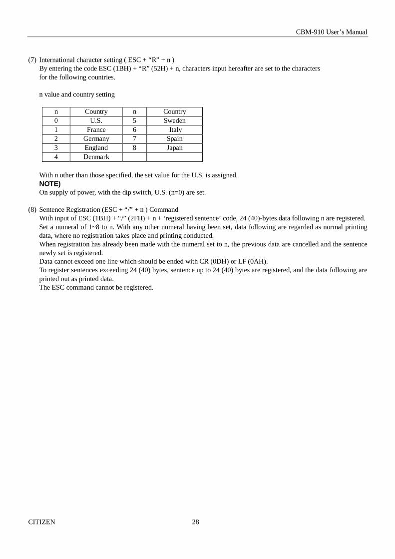
(7) International character setting ( ESC + “R” + n )By entering the code ESC (1BH) + “R” (52H) + n, characters input hereafter are set to the charactersfor the following countries.
n value and country setting
n Country n Country0 U.S. 5 Sweden1 France 6 Italy2 Germany 7 Spain3 England 8 Japan4 Denmark
With n other than those specified, the set value for the U.S. is assigned.NOTE)On supply of power, with the dip switch, U.S. (n=0) are set.
(8) Sentence Registration (ESC + “/” + n ) CommandWith input of ESC (1BH) + “/” (2FH) + n + ‘registered sentence’ code, 24 (40)-bytes data following n are registered.Set a numeral of 1~8 to n. With any other numeral having been set, data following are regarded as normal printingdata, where no registration takes place and printing conducted.When registration has already been made with the numeral set to n, the previous data are cancelled and the sentencenewly set is registered.Data cannot exceed one line which should be ended with CR (0DH) or LF (0AH).To register sentences exceeding 24 (40) bytes, sentence up to 24 (40) bytes are registered, and the data following areprinted out as printed data.The ESC command cannot be registered.

CBM-910 User’s Manual
CITIZEN 29
(9) Registered Sentence Printing (ESC + “!” + n) CommandWith ESC (1BH) + “!” (21H) + n code input, sentence already registered in the numeral assigned to n are printed.Assign, to n, a numeral of 1 to 8. With any other numeral having been set, no execution takes place.NOTE 1)As much as 24 (40) bytes of data can be registered. In case that 24 (40) columns are exceeded on printing (because ofenlarged or x 4 letters having been assigned, etc.), printing is conducted up to 24(40)th column and the columnsoverflowed are printed in the next line. Be sure to make registration in consideration of printing results.NOTE 2)With x 4 enlargement or inverted letters executed at printing, printing continues in that setting unless they arecancelled.
Application Example 1)[Receiving Data]
ESC / 1 This is a pen CR Sentence registered in 1.
ESC / 9 Is this a pen ? CR No registration made with 9.
ESC / 1 It is a pen CR Overwritten on sentence registered initially in 1.
ESC ! 1 Printing of sentence registered in 1.
<Registered State>
1 It is a pen2345678
<Printing Result>
Is th is a pen ? Registration with 9 was invalid It is a pen Immediately printed because not being within 1~8 scope.
Printed out with ESC + “ !” + 1.

CBM-910 User’s Manual
CITIZEN 30
Application Example 2)[Receiving Data]
ESC / 1 This is a pen CR
No. of columns has overflowed.
ESC / 2 Japan CBM Corporation Micro CR
ESC / 4 SO CITIZEN SI NEW PRODUCTS CR
enlargement canceled
Is this a pen ? CR
ESC ! 4
ESC ! 1
ESC ! 2
Impact dot printer CR
<Registered State>
1 This is a pen
2 Japan CBM Corporation Mi
3
4 SO CITIZEN SI NEW PRODUCTS
5
6
7
8
<Printed Result>
cro ← Directly printed out since overflow hasoccurred.
Is this a pen ?C IT IZ E N NEW PRODUCTSThis is a penJapan CBM Corporation MiImpact dot printer
CBM-910 User’s Manual
CITIZEN 31
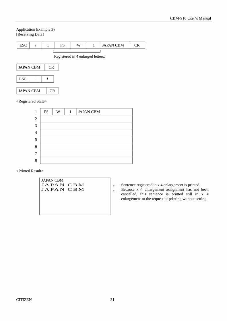
Application Example 3)[Receiving Data]
ESC / 1 FS W 1 JAPAN CBM CR
Registered in 4 enlarged letters.
JAPAN CBM CR
ESC ! !
JAPAN CBM CR
<Registered State>
1 FS W 1 JAPAN CBM
2
3
4
5
6
7
8
<Printed Result>
JAPAN CBMJA PA N C B MJA PA N C B M
←←
Sentence registered in x 4 enlargement is printed.Because x 4 enlargement assignment has not beencancelled, this sentence is printed still in x 4enlargement to the request of printing without setting.

CBM-910 User’s Manual
CITIZEN 32
(10) Character registration (ESC + “&”) command1. For 24-column model (ESC + “&” + A1 + A2)
Individual patterns can be registered by entering the code ESC + & + A1 + A2, then entering the pattern data.A maximum of 8 characters can be registered, and any address in the range of 20H to FFH can be used for theregistration. However, if a new pattern is registered in an address already in use, existing data is cleared and thenewly entered data becomes valid. If more than 8 characters are registered, all existing character registration iscleared.
[Address setting]Specified address is matched to the character code and can be accessed likewise to the stored fixed character record.If a fixed character is defined in the specified address, the fixed character becomes invalid. A1 signifies the startingaddress for the registrations A2 is the ending address.
[Method of data transmission]d-1 Single character registrationSelect the address to be defied (character code) from among 20H to FFH and designate is as A1. When registering asingle character, starting and ending addresses match each other. That is, A1=A2.<Example>A6 × 6 dot matrix full dot pattern is to be registered in address 41H (code for the fixed character “A”). (Numerals arehexadecimal.)
ESC + “&” + A1 + A2 + “Pattern data (6 byte)”1B 26 41 41 FF•FF•FF•FF•FF•FF
In the successive controls, a 6 × 8 dot matrix full dot is output whenever the character code 41H is specified.(Character “A” cannot be accessed.)
d-2 Multiple character registrationBy repeating the single character registration, a maximum of 8 characters can be registered. When defining multiplecharacters in a successive address (character code), register pattern data for a maximum of 8 characters bydesignation A1 as the starting address and A2 as the ending address.Note)A1<A2, A2 – A1≤ 7

CBM-910 User’s Manual
CITIZEN 33
[Pattern Data Configuration](For 24-Column Model)Pattern data to be registered must consist of 6 bytes per character.That is, pattern data configured by a 6 × 8 dot matrix is broken up into 6 vertically positioned units each of which isrepresented by 1 byte of data. All together, 6 bytes of data are transmitted.<Example> When transmitting the following data.
[Printing of Registered Letters]To print registered character, in the same manner as printing other fixed characters, use the commands(CR, LF, ESC + “B” + n).
2. For 40-Column Model (ESC + “&” + C1 + A1 + A2)With ESC (1BH) + “&” (26H) + C1 + A1 + A2 code and the pattern data following input, a pattern is registered.Total 224 characters are available for registration into addresses of 20H ~ FFH.When two pattern data have registered in the same address, those initially registered are cleared and the new dataalone are made valid.
[Recognition of Use of Uppermost Bit]For recognition of use or non-use of the uppermost bit by a character to be registered, set data to Parameter C1.
C1=0 (00H) : Uppermost bit not used.Other than C1=0 : Uppermost bit used.
With 0 set to this parameter while the uppermost bit is in use, ×4 enlargement results in incomplete images for whichthe uppermost part is lacking.
[Setting of Addresses]A1 : Registration starting address (20H~FFH)A2 : Registration ending address (20H~FFH)

CBM-910 User’s Manual
CITIZEN 34
[Pattern Data Configuration](For 40-Column Model)Pattern data to be registered must consist of 9 bytes per character. That is, pattern data configured by 9×8 dot matrixis broken up into 9 vertically each of which is represented by 1 byte of data.All together, 9 bytes of data are transmitted.<Example>When transmitting the following pattern data :
Pattern data (9 bytes)As the model utilizes the half-dot printing method. It is not capable of positing successive dots in the printing(lateral) direction. Therefore, pattern, even if assigned in the position “*” to the right of “•” in the diagram above,will not be registered as pattern data.

CBM-910 User’s Manual
CITIZEN 35
NOTE)With 0 being set in “C1” parameter even if data have been registered in the uppermost position,letter image registered is made incomplete.
(11) Registered Letter Valid / Invalid (ESC + “%” + n) CommandWhether a registered pattern is valid or invalid is set with ESC (1BH) + “%” (26H) + n code being input.n = 1 (01H) : Registered pattern to be made valid. (Addresses for which no registration change has been conducted
are taken as inside fixed characters.)n = 0 (00H) : Registered pattern to be made invalid. (Taken as in side fixed character sets.)
The initial setting is 0 (inside fixed character).Even with letters already registered by pattern registration, printing of registered letters cannot be effectuatedunless the patterns registered are mode valid with this command.NOTE)This command is applicable only to the 40-column printer.

CBM-910 User’s Manual
CITIZEN 36
(12) Bit Image Printing (ESC + “K” + n1 + n2 + n3) CommandWith ESC (1BH) + K (4BH) + n1 + n2 + n3 code being input, conversation from Text mode into Bit Image modetakes place. The n1/n2/n3 assigns amount of transmission of bit image data which follows these.Where, n1 represents the no. of bytes in lateral direction and n2 (lowermost)/n31 (uppermost) representthe no. of dot lines vertical direction.
(Relations Between Data and Print-Out)
(Parameter Assignable Range)
Model n1 n2 n324 columns 1~18 0~255 0~140 columns 1~23 0~255 0~1
In case that assignment has been made out of the assignable range or n2 = n3 = 0 has been assigned, Bit Image modeis cancelled and Text mode starts.With this printer, on completion of read-in of 4-dot-line data or on completion of n1/ n2/n3 assigning data, lackingdata are printed as spaces.NOTE 1)With n1 = 23 having been assigned in 40-column Model, 4 dots from the lowermost column (LSB) are made invalid.This is because the printing position in one line equals 180 dots.NOTE 2)On termination of bit image printing, Text mode is reinstated.

CBM-910 User’s Manual
CITIZEN 37
(13) ×4 Enlarged Letter Assignment (FS + “W” + 1) CommandWith FS (1CH) + “W” (57H) + 1 (01H) code input, ×4 enlarged letters are assigned.Data following this code are printed vertically and laterally twice enlarged.
(14) ×4 Enlargement Cancel (FS + “W” + 0)With FS (1CH) + “W” (57H) + 0(00H) code being input, ×4 enlargement assignment is cancelled.NOTE 1)Although standard and laterally enlarged letters can coexist in one line, automatic (buffer-full) printing takes placeon reaching to 24th (40th) column counted in standard characters.NOTE 2)With both ×4 enlargement and double-width having been assigned, ×4 enlargement has priority.
Application Example) [Receiving Data]
1C W 1 123456789 CR
1C W 0 ABC 1C W 1 123 CR
1C W 0 A 1C W 1 12345678901B
<Printing Results>
1 2 3 4 5 6 7 8 9ABC 1 2 3A 1 2 3 4 5 6 7 8 9 0 1 B
↑ The last letter, although in ×4 assignment, is printed in standard lettersince it being in the 24th column.(For 40 column mechanism, this applies to the 40th column.)

CBM-910 User’s Manual
CITIZEN 38
9. CHARACTER SET
9.1 U.S.A. Specifications

CBM-910 User’s Manual
CITIZEN 39
9.2 Character code Table (*1 - *12 in the following code table are placed in the next page under ESC+R+n command.)

CBM-910 User’s Manual
CITIZEN 40
International Character Set
Character Codes

CBM-910 User’s Manual
CITIZEN 41
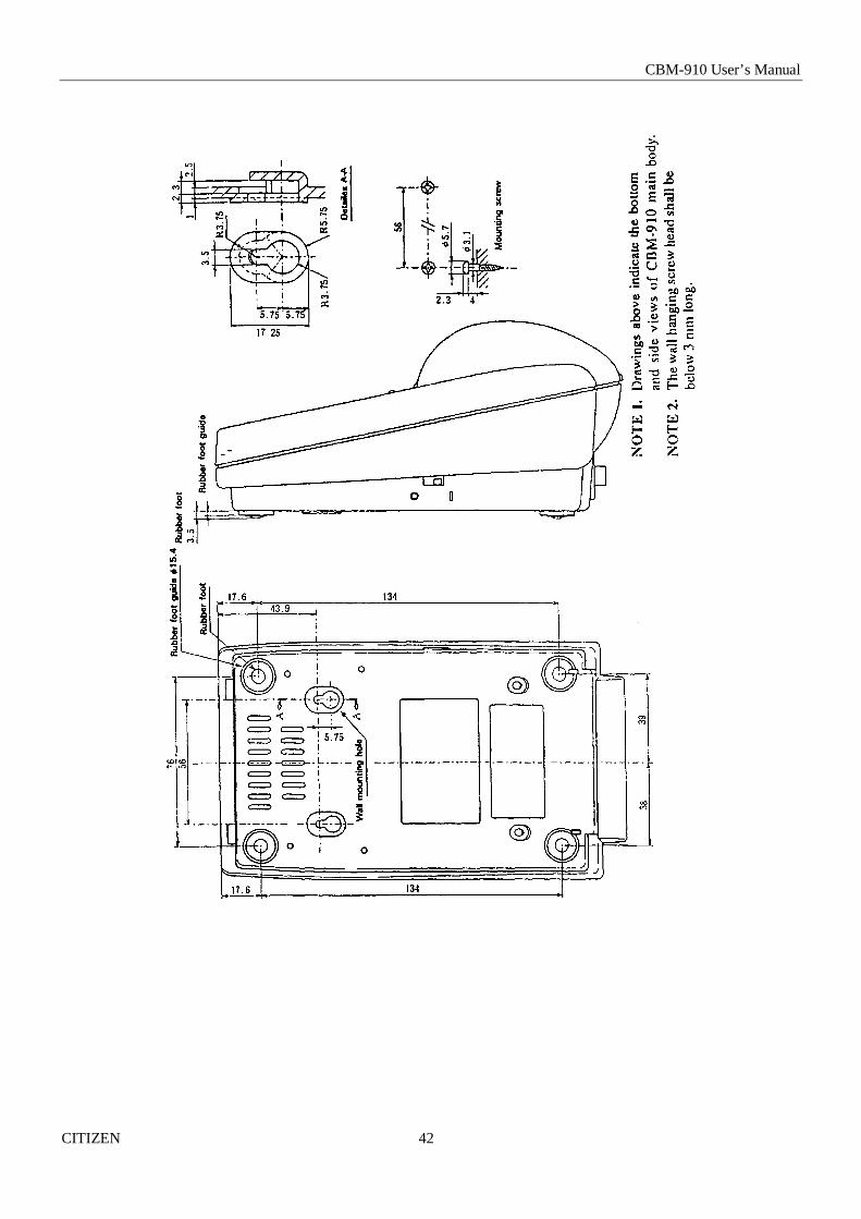
10. EXTERNAL DIMENSIONS (in mm)
CBM-910 User’s Manual
CITIZEN 42

Information Systems Division CBM Bldg., 5-68-10, Nakano, Nakano-ku, Tokyo 164-0001, Japan
Head Office Tel: (+81-3) 5345-7540 Fax: (+81-3) 5345-7541
13E-20000208-1500-0048-02.25 Printed in Japan