DOOR TECHNOLOGY Panic exit devices in accordance with EN ... · Panic exit and emergency exit...
64
Panic exit and emergency exit devices for narrow stile doors Panic exit and emergency exit devices for timber and steel doors Accessories for narrow stile, timber and steel doors Useful information Edition 04/2015 DOOR TECHNOLOGY Panic exit devices in accordance with EN 1125 Emergency exit devices in accordance with EN 179
-
Upload
truongdang -
Category
Documents
-
view
245 -
download
2
Transcript of DOOR TECHNOLOGY Panic exit devices in accordance with EN ... · Panic exit and emergency exit...
Panic exit and emergency exit devices for narrow stile doors
Panic exit and emergency exit devices for timber and steel doors
Accessories for narrow stile, timber and steel doors
Useful information
Edition 04/2015
DOOR TECHNOLOGY
Panic exit devices in accordance with EN 1125
Emergency exit devices in accordance with EN 179
GU І WP02019-04-2-1 І 04/2015
A corporate group with
tradition
For over 100 years, the owner-
managed GU Group has been
fascinated with the opening,
swinging, closing and locking
of windows and doors. Techni-
cal innovations and continual
development of architectural
hardware technology have and
will continue to shape forces
in the market, setting new
standards and trends for the
future.
The Gretsch-Unitas Group
The corporate group consists
of more than 50 manufacturing
and distribution companies
in 35 countries. With the
internationally leading brands
GU (architectural hardware),
BKS (locks, locking systems)
and FERCO (architectural
hardware), the group off ers
"Securing Technology for You".
Corporate group
product overview
In its window technology, door
technology, automatic entran-
ce systems and building ma-
nagement systems divisions,
the GU Group manufactures
and distributes about 30,000
single items which are easy to
combine.
Securing technology for you
We use the major challenges
of creating innovative und
visionary system solutions to
break new ground. Together
with architects, planners and
profi le system manufacturers,
we develop individual compre-
hensive solutions.
Tradition obliges – leading standards in design and qualityW
ith
kin
d p
erm
issi
on
of:
ka
b p
lan
un
gsb
üro
fü
r b
au
leis
tun
ge
n g
mb
h, F
ell
ba
ch
2

GU І WP02019-04-2-1 І 04/2015
Table of contents
Lock & hardware combinations to EN 179 and EN 1125 5 – 15
Locks for single and double leaf doors 16 – 21
Strikers 22 – 23
Door hardware to EN 1906, EN 179 and EN 1125 24 – 27
Panic exit and emergency exit devices for narrow stile doors
Lock & hardware combinations to EN 179 and EN 1125 29 – 39
Locks for single and double leaf doors 40 – 43
Strikers 44 – 45
Door hardware to EN 1906, EN 179 and EN 1125 46 – 51
Panic exit and emergency exit devices for timber and steel doors
Miscellaneous 52 – 54
Square spindles / Screws 55 – 57
Accessories for narrow stile, timber and steel doors
Product liability 58
Standards and regulations 59
Panic function B 60
Panic function E 61
Instructions for use 62 – 63
Exclusion of liability / Copyright notice / Image credits 63
General information
Overview
3
GU І WP02019-04-2-1 І 04/2015
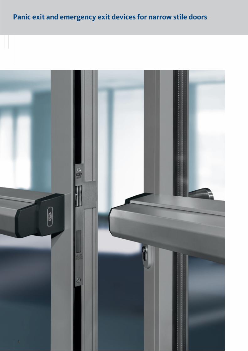
Panic exit and emergency exit devices for narrow stile doors
4

Panic exit and emergency exit devices for narrow stile doors
GU І WP02019-04-2-1 І 04/2015
Lock & hardware combinations to EN 179 and EN 1125
Inside view Outside view
Combination 1 to EN 179 Page 6 – 7
B-1126 panic lock
B 9000 striker
Door hardware
Combination 2 to EN 1125 Page 8 – 9
B-1126 panic lock
B 9000 striker
Door hardware
Combination 2a to EN 1125 Page 10 – 11
B 1316 panic lock
B 9000 striker
Door hardware
Combination 3 to EN 179 Page 12 – 13
B-1126 panic lock
B-1126 shoot-bolt lock
Door hardware
B 1895 passive-leaf control lock
B 9006 vertical rod, top
B 9006 vertical rod, bottom
B 9000 striker
B 9009 fl oor striker
B 9019 guide plate for vertical rod
Combination 4 to EN 1125 Page 14 – 15
B-1126 panic lock
B-1126 shoot-bolt lock
Door hardware
B 1895 passive-leaf control lock
B 9006 vertical rod, top
B 9006 vertical rod, bottom
B 9000 striker
B 9009 fl oor striker
B 9019 guide plate for vertical rod
5
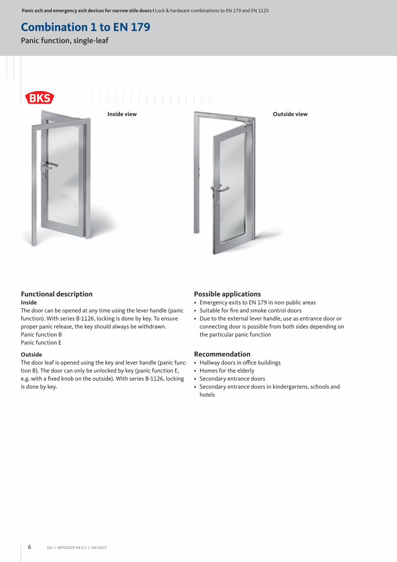
Panic exit and emergency exit devices for narrow stile doors І Lock & hardware combinations to EN 179 and EN 1125
GU І WP02019-04-2-1 І 04/2015
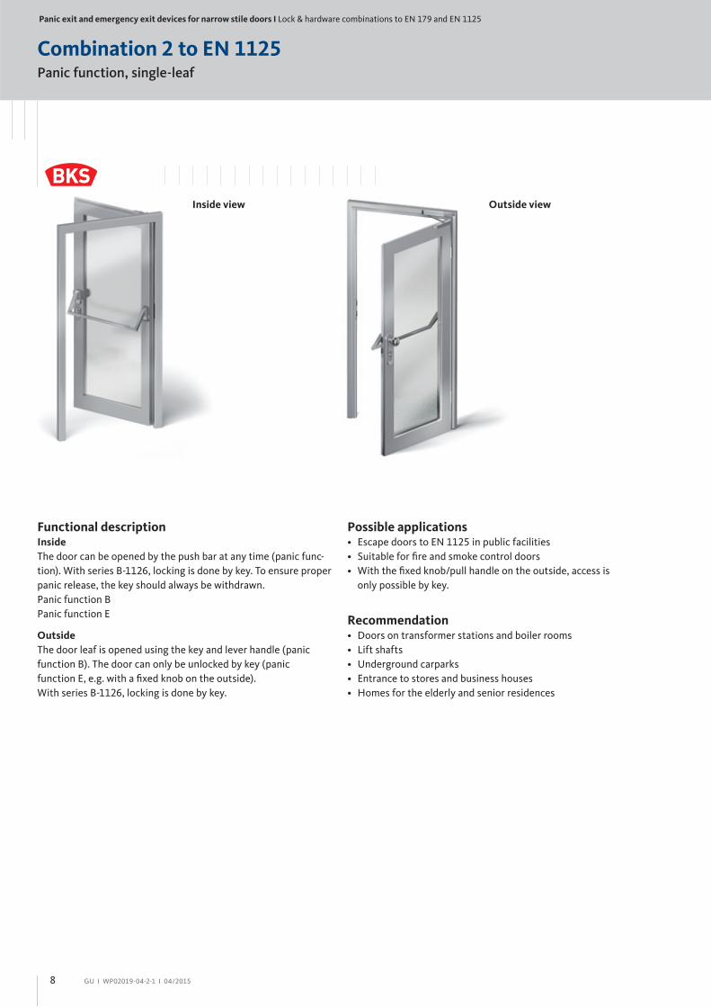
Functional descriptionInside
The door can be opened at any time using the lever handle (panic
function). With series B-1126, locking is done by key. To ensure
proper panic release, the key should always be withdrawn.
Panic function B
Panic function E
Outside
The door leaf is opened using the key and lever handle (panic func-
tion B). The door can only be unlocked by key (panic function E,
e.g. with a fi xed knob on the outside). With series B-1126, locking
is done by key.
Possible applications• Emergency exits to EN 179 in non-public areas
• Suitable for fi re and smoke control doors
• Due to the external lever handle, use as entrance door or
connecting door is possible from both sides depending on
the particular panic function
Recommendation• Hallway doors in offi ce buildings
• Homes for the elderly
• Secondary entrance doors
• Secondary entrance doors in kindergartens, schools and
hotels
Inside view Outside view
Combination 1 to EN 179Panic function, single-leaf
6

GU І WP02019-04-2-1 І 04/2015
Combination 1 to EN 179Panic function, single-leaf
Active leaf
No. Product / FunctionBacksetin mm
Faceplate 24 x 3 x 270 mmsee page
DIN LH DIN RH
1
1126 /Panic function B
35 B-11260-07-L-8 B-11260-07-R-8 17
40 B-11260-08-L-8 B-11260-08-R-8 17
45 B-11260-09-L-8 B-11260-09-R-8 17
Non-handed
1126 /Panic function E
35 B-11260-13-U-8 17
40 B-11260-14-U-8 17
45 B-11260-15-U-8 17
2
1
Active leaf:
= Panic lock
= Striker
= Door closer
1
2
Frame
No. Product see page
2Flat striker B 9000 1045 22
U-striker B 9000 1218 22
3 For door closers refer to our catalogue WP00600-04-2-1
Door hardware to EN 179
Narrow stile rosette, stainless steel
Product see page
Lever set, panic function B B-72030-01-0-8 24
Panic function E B-72330-01-0-8 25
3
3
7
Panic exit and emergency exit devices for narrow stile doors І Lock & hardware combinations to EN 179 and EN 1125
GU І WP02019-04-2-1 І 04/2015
Combination 2 to EN 1125Panic function, single-leaf
Inside view Outside view
Functional descriptionInside
The door can be opened by the push bar at any time (panic func-
tion). With series B-1126, locking is done by key. To ensure proper
panic release, the key should always be withdrawn.
Panic function B
Panic function E
Outside
The door leaf is opened using the key and lever handle (panic
function B). The door can only be unlocked by key (panic
function E, e.g. with a fi xed knob on the outside).
With series B-1126, locking is done by key.
Possible applications• Escape doors to EN 1125 in public facilities
• Suitable for fi re and smoke control doors
• With the fi xed knob/pull handle on the outside, access is
only possible by key.
Recommendation• Doors on transformer stations and boiler rooms
• Lift shafts
• Underground carparks
• Entrance to stores and business houses
• Homes for the elderly and senior residences
8
GU І WP02019-04-2-1 І 04/2015
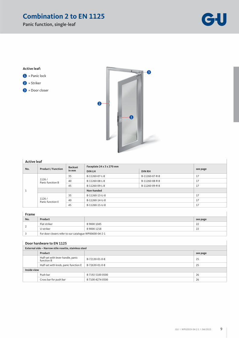
Combination 2 to EN 1125Panic function, single-leaf
Active leaf:
= Panic lock
= Striker
= Door closer
1
2
2
1
Frame
No. Product see page
2Flat striker B 9000 1045 22
U-striker B 9000 1218 22
3 For door closers refer to our catalogue WP00600-04-2-1
Door hardware to EN 1125
External side – Narrow stile rosette, stainless steel
Product see page
Half-set with lever handle, panic function B
B-72130-01-0-8 25
Half-set with knob, panic function E B-72630-01-0-8 25
Inside view
Push bar B 7192 5100 0500 26
Cross bar for push bar B 7100 4274 0500 26
Active leaf
No. Product / FunctionBacksetin mm
Faceplate 24 x 3 x 270 mmsee page
DIN LH DIN RH
1
1126 /Panic function B
35 B-11260-07-L-8 B-11260-07-R-8 17
40 B-11260-08-L-8 B-11260-08-R-8 17
45 B-11260-09-L-8 B-11260-09-R-8 17
Non-handed
1126 /Panic function E
35 B-11260-13-U-8 17
40 B-11260-14-U-8 17
45 B-11260-15-U-8 17
3
3
9
Panic exit and emergency exit devices for narrow stile doors І Lock & hardware combinations to EN 179 and EN 1125
GU І WP02019-04-2-1 І 04/2015
Combination 2a to EN 1125Panic function, single-leaf
Inside view Outside view
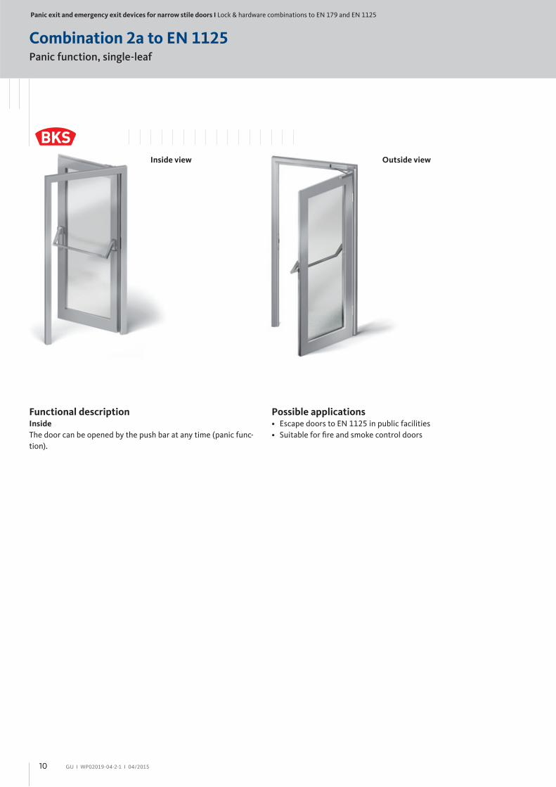
Functional descriptionInside
The door can be opened by the push bar at any time (panic func-
tion).
Possible applications• Escape doors to EN 1125 in public facilities
• Suitable for fi re and smoke control doors
10

GU І WP02019-04-2-1 І 04/2015
Combination 2a to EN 1125Panic function, single-leaf
Active leaf:
= Panic lock
= Striker
= Door closer
1
2
2
1
3
3
Frame
No. Product see page
2Flat striker B 9000 1097 22
U-striker B 9000 1098 22
3 For door closers refer to our catalogue WP00600-04-2-1
Door hardware to EN 1125
Inside view
Product see page
Push bar B 7100 5100 0500 26
Cross bar for push bar B 7100 4274 0500 26
Active leaf
No. Product / FunctionBacksetin mm
Faceplate 24 x 3 x 160 mm U-faceplate 24 x 6 x 160 mmsee page
DIN LH DIN RH DIN LH DIN RH
1 1316
35 B 1316 2003 B 1316 2004 B 1316 2023 B 1316 2024 20
40 B 1316 2005 B 1316 2006 B 1316 2025 B 1316 2026 20
45 B 1316 2007 B 1316 2008 B 1316 2027 B 1316 2028 20
11
Panic exit and emergency exit devices for narrow stile doors І Lock & hardware combinations to EN 179 and EN 1125
GU І WP02019-04-2-1 І 04/2015
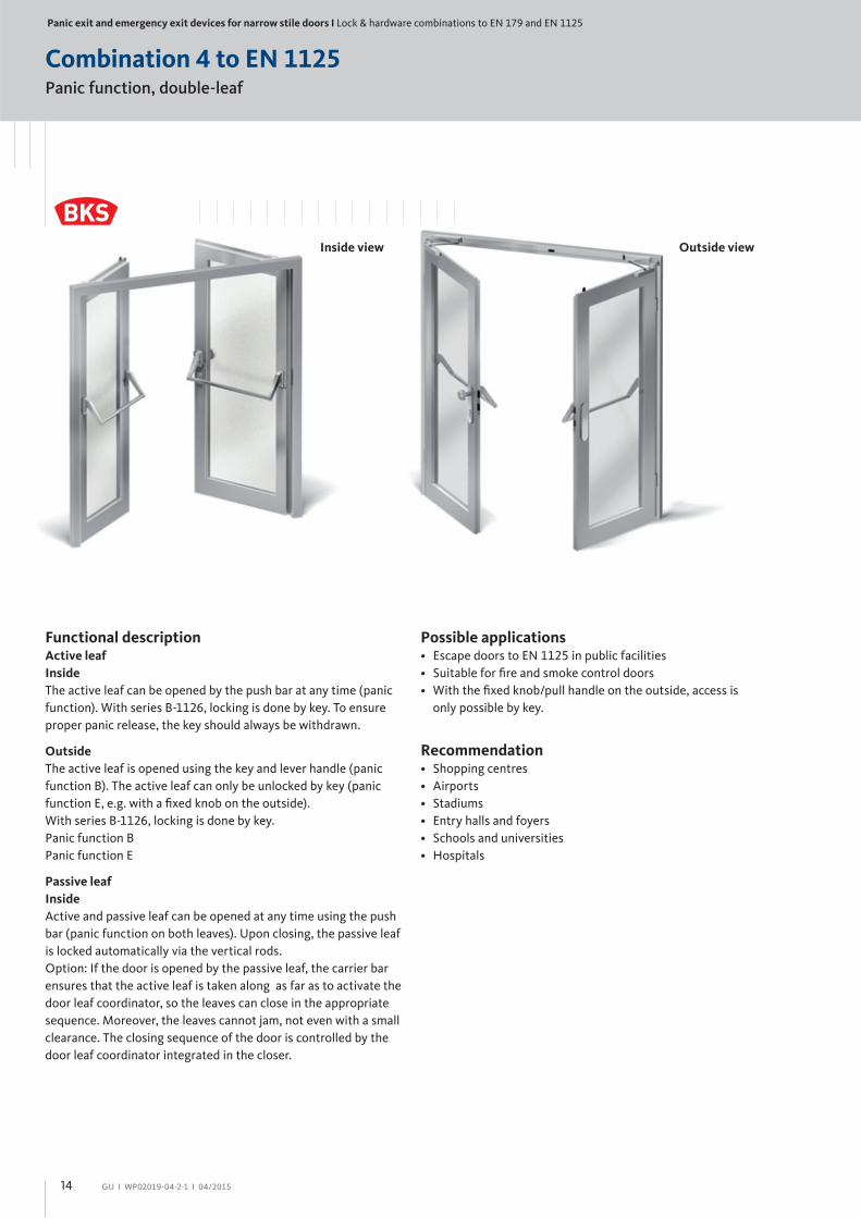
Combination 3 to EN 179Panic function, double-leaf
Inside view Outside view
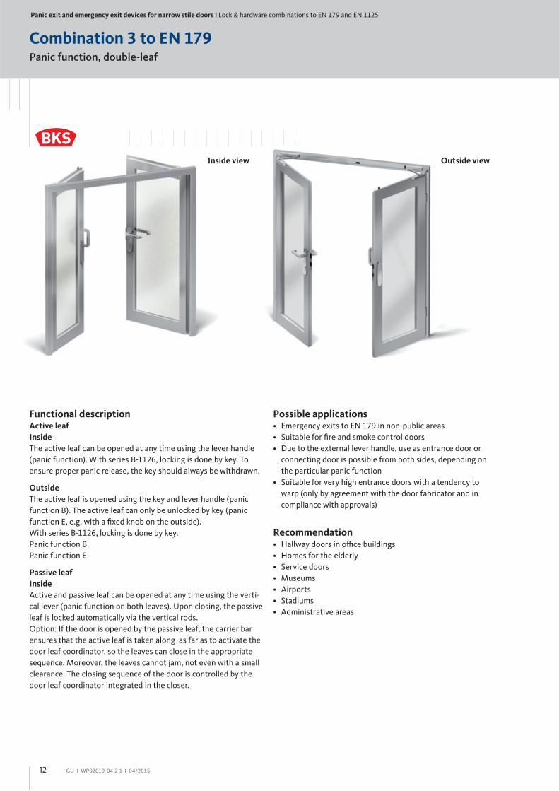
Functional descriptionActive leaf
Inside
The active leaf can be opened at any time using the lever handle
(panic function). With series B-1126, locking is done by key. To
ensure proper panic release, the key should always be withdrawn.
Outside
The active leaf is opened using the key and lever handle (panic
function B). The active leaf can only be unlocked by key (panic
function E, e.g. with a fi xed knob on the outside).
With series B-1126, locking is done by key.
Panic function B
Panic function E
Passive leaf
Inside
Active and passive leaf can be opened at any time using the verti-
cal lever (panic function on both leaves). Upon closing, the passive
leaf is locked automatically via the vertical rods.
Option: If the door is opened by the passive leaf, the carrier bar
ensures that the active leaf is taken along as far as to activate the
door leaf coordinator, so the leaves can close in the appropriate
sequence. Moreover, the leaves cannot jam, not even with a small
clearance. The closing sequence of the door is controlled by the
door leaf coordinator integrated in the closer.
Possible applications• Emergency exits to EN 179 in non-public areas
• Suitable for fi re and smoke control doors
• Due to the external lever handle, use as entrance door or
connecting door is possible from both sides, depending on
the particular panic function
• Suitable for very high entrance doors with a tendency to
warp (only by agreement with the door fabricator and in
compliance with approvals)
Recommendation• Hallway doors in offi ce buildings
• Homes for the elderly
• Service doors
• Museums
• Airports
• Stadiums
• Administrative areas
12

GU І WP02019-04-2-1 І 04/2015
Combination 3 to EN 179Panic function, double-leaf
Passive leaf:
= Shoot-bolt lock
= Control lock
= Vertical rod
= Solid vertical rod
= Striker
= Floor striker
= Guide plate for vertical rod
= Door closer
2
3
4
5
6
7
8
Active leaf:
= Panic lock
= Door closer
1
7
8
3
4
2
5
1
6
Passive leaf
No. ProductBacksetin mm
Faceplate 24 x 3 x 235 mmsee page
Non-handed
2 1126 35 B-11260-31-U-8 19
3 1895 35 B 1895 0003 0500 52
4 9006 with end plug B 9006 0013 0500 52
5 9006 solid B 9006 0004 0500 53
6 9000 for 9006 B 9000 0490 23
7 9009 – B 9009 0001 0500 53
8 9019 – B 9019 0001 0500 54
9 For door closers refer to our catalogue WP00600-04-2-1
Door hardware to EN 179
Narrow stile rosette, stainless steel
Product see page
Lever set, panic function B B-72030-01-0-8 24
Panic function E B-72330-01-0-8 25
Vertical lever B-72130-41-0-8 25
Active leaf
No. Product / FunctionBacksetin mm
Faceplate 24 x 3 x 270 mmsee page
DIN LH DIN RH
1
1126 /Panic function B
35 B-11260-19-L-8 B-11260-19-R-8 18
40 B-11260-20-L-8 B-11260-20-R-8 18
45 B-11260-21-L-8 B-11260-21-R-8 18
Non-handed
1126 /Panic function E
35 B-11260-25-U-8 18
40 B-11260-26-U-8 18
45 B-11260-27-U-8 18
9
9
9
9
13
Panic exit and emergency exit devices for narrow stile doors І Lock & hardware combinations to EN 179 and EN 1125
GU І WP02019-04-2-1 І 04/2015
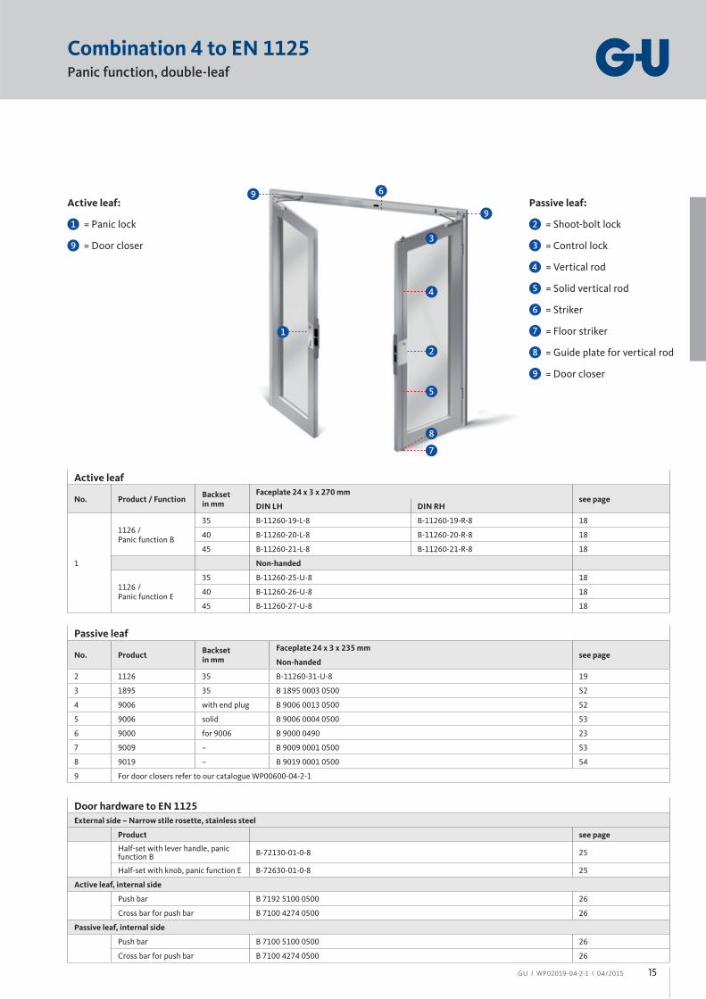
Combination 4 to EN 1125Panic function, double-leaf
Inside view Outside view
Functional descriptionActive leaf
Inside
The active leaf can be opened by the push bar at any time (panic
function). With series B-1126, locking is done by key. To ensure
proper panic release, the key should always be withdrawn.
Outside
The active leaf is opened using the key and lever handle (panic
function B). The active leaf can only be unlocked by key (panic
function E, e.g. with a fi xed knob on the outside).
With series B-1126, locking is done by key.
Panic function B
Panic function E
Passive leaf
Inside
Active and passive leaf can be opened at any time using the push
bar (panic function on both leaves). Upon closing, the passive leaf
is locked automatically via the vertical rods.
Option: If the door is opened by the passive leaf, the carrier bar
ensures that the active leaf is taken along as far as to activate the
door leaf coordinator, so the leaves can close in the appropriate
sequence. Moreover, the leaves cannot jam, not even with a small
clearance. The closing sequence of the door is controlled by the
door leaf coordinator integrated in the closer.
Possible applications• Escape doors to EN 1125 in public facilities
• Suitable for fi re and smoke control doors
• With the fi xed knob/pull handle on the outside, access is
only possible by key.
Recommendation• Shopping centres
• Airports
• Stadiums
• Entry halls and foyers
• Schools and universities
• Hospitals
14
GU І WP02019-04-2-1 І 04/2015
Combination 4 to EN 1125Panic function, double-leaf
Passive leaf:
= Shoot-bolt lock
= Control lock
= Vertical rod
= Solid vertical rod
= Striker
= Floor striker
= Guide plate for vertical rod
= Door closer
2
3
4
5
6
7
8
Active leaf:
= Panic lock
= Door closer
1
7
8
3
4
2
5
1
6
Passive leaf
No. ProductBacksetin mm
Faceplate 24 x 3 x 235 mmsee page
Non-handed
2 1126 35 B-11260-31-U-8 19
3 1895 35 B 1895 0003 0500 52
4 9006 with end plug B 9006 0013 0500 52
5 9006 solid B 9006 0004 0500 53
6 9000 for 9006 B 9000 0490 23
7 9009 – B 9009 0001 0500 53
8 9019 – B 9019 0001 0500 54
9 For door closers refer to our catalogue WP00600-04-2-1
Door hardware to EN 1125
External side – Narrow stile rosette, stainless steel
Product see page
Half-set with lever handle, panic function B
B-72130-01-0-8 25
Half-set with knob, panic function E B-72630-01-0-8 25
Active leaf, internal side
Push bar B 7192 5100 0500 26
Cross bar for push bar B 7100 4274 0500 26
Passive leaf, internal side
Push bar B 7100 5100 0500 26
Cross bar for push bar B 7100 4274 0500 26
Active leaf
No. Product / FunctionBacksetin mm
Faceplate 24 x 3 x 270 mmsee page
DIN LH DIN RH
1
1126 /Panic function B
35 B-11260-19-L-8 B-11260-19-R-8 18
40 B-11260-20-L-8 B-11260-20-R-8 18
45 B-11260-21-L-8 B-11260-21-R-8 18
Non-handed
1126 /Panic function E
35 B-11260-25-U-8 18
40 B-11260-26-U-8 18
45 B-11260-27-U-8 18
9
9
9
9
15
Panic exit and emergency exit devices for narrow stile doors І Locks for single and double-leaf doors
GU І WP02019-04-2-1 І 04/2015
for single-leaf doors
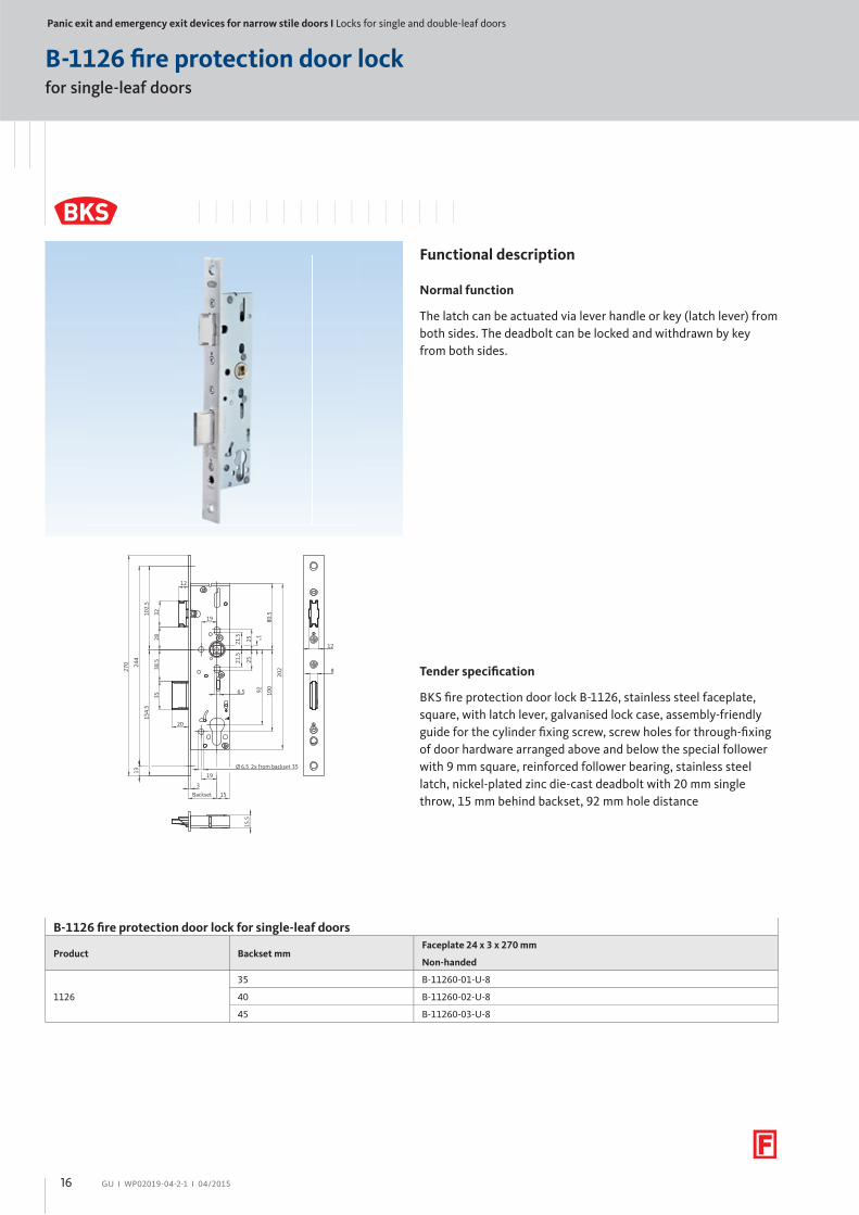
B-1126 fi re protection door lock
Functional description
Normal function
The latch can be actuated via lever handle or key (latch lever) from
both sides. The deadbolt can be locked and withdrawn by key
from both sides.
15.5
Backset
270 24
4
3528
15
20
12
38.5
102.
5
1°
21.5
25
21.5
25
100
80.5
92
202
19
19Ø 2x from backset 356.5
13
154.
5
32
6.5
3
12
8 Tender specifi cation
BKS fi re protection door lock B-1126, stainless steel faceplate,
square, with latch lever, galvanised lock case, assembly-friendly
guide for the cylinder fi xing screw, screw holes for through-fi xing
of door hardware arranged above and below the special follower
with 9 mm square, reinforced follower bearing, stainless steel
latch, nickel-plated zinc die-cast deadbolt with 20 mm single
throw, 15 mm behind backset, 92 mm hole distance
B-1126 fi re protection door lock for single-leaf doors
Product Backset mmFaceplate 24 x 3 x 270 mm
Non-handed
1126
35 B-11260-01-U-8
40 B-11260-02-U-8
45 B-11260-03-U-8
16
GU І WP02019-04-2-1 І 04/2015
for single-leaf doors
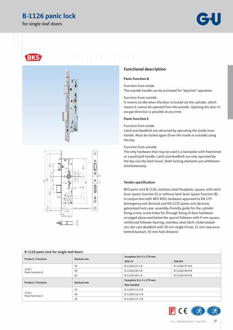
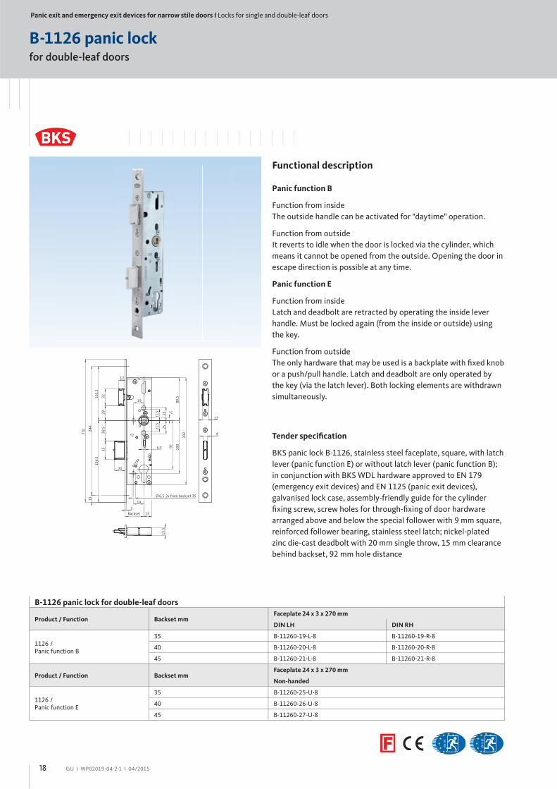
B-1126 panic lock
Functional description
Panic function B
Function from inside
The outside handle can be activated for "daytime" operation.
Function from outside
It reverts to idle when the door is locked via the cylinder, which
means it cannot be opened from the outside. Opening the door in
escape direction is possible at any time.
Panic function E
Function from inside
Latch and deadbolt are retracted by operating the inside lever
handle. Must be locked again (from the inside or outside) using
the key.
Function from outside
The only hardware that may be used is a backplate with fi xed knob
or a push/pull handle. Latch and deadbolt are only operated by
the key (via the latch lever). Both locking elements are withdrawn
simultaneously.
15.5
Backset
270 24
4
3528
15
20
12
38.5
102.
5
1°
21.5
25
21.5
25
100
80.5
92
202
19
19Ø 2x from backset 356.5
13
154.
5
32
6.5
3
12
8 Tender specifi cation
BKS panic lock B-1126, stainless steel faceplate, square, with latch
lever (panic function E) or without latch lever (panic function B);
in conjunction with BKS WDL hardware approved to EN 179
(emergency exit devices) and EN 1125 (panic exit devices),
galvanised lock case, assembly-friendly guide for the cylinder
fi xing screw, screw holes for through-fi xing of door hardware
arranged above and below the special follower with 9 mm square,
reinforced follower bearing, stainless steel latch; nickel-plated
zinc die-cast deadbolt with 20 mm single throw, 15 mm clearance
behind backset, 92 mm hole distance
B-1126 panic lock for single-leaf doors
Product / Function Backset mmFaceplate 24 x 3 x 270 mm
DIN LH DIN RH
1126 /Panic function B
35 B-11260-07-L-8 B-11260-07-R-8
40 B-11260-08-L-8 B-11260-08-R-8
45 B-11260-09-L-8 B-11260-09-R-8
Product / Function Backset mmFaceplate 24 x 3 x 270 mm
Non-handed
1126 /Panic function E
35 B-11260-13-U-8
40 B-11260-14-U-8
45 B-11260-15-U-8
17
Panic exit and emergency exit devices for narrow stile doors І Locks for single and double-leaf doors
GU І WP02019-04-2-1 І 04/2015
for double-leaf doors
B-1126 panic lock
Functional description
Panic function B
Function from inside
The outside handle can be activated for "daytime" operation.
Function from outside
It reverts to idle when the door is locked via the cylinder, which
means it cannot be opened from the outside. Opening the door in
escape direction is possible at any time.
Panic function E
Function from inside
Latch and deadbolt are retracted by operating the inside lever
handle. Must be locked again (from the inside or outside) using
the key.
Function from outside
The only hardware that may be used is a backplate with fi xed knob
or a push/pull handle. Latch and deadbolt are only operated by
the key (via the latch lever). Both locking elements are withdrawn
simultaneously.
15.5
Backset
270 24
4
3528
15
20
12
38.5
102.
5
1°
21.5 25
21.5
25
100
80.5
92
202
19
19
Ø 2x from backset 356.5
13
154.
5
32
6.5
3
12
8 Tender specifi cation
BKS panic lock B-1126, stainless steel faceplate, square, with latch
lever (panic function E) or without latch lever (panic function B);
in conjunction with BKS WDL hardware approved to EN 179
(emergency exit devices) and EN 1125 (panic exit devices),
galvanised lock case, assembly-friendly guide for the cylinder
fi xing screw, screw holes for through-fi xing of door hardware
arranged above and below the special follower with 9 mm square,
reinforced follower bearing, stainless steel latch; nickel-plated
zinc die-cast deadbolt with 20 mm single throw, 15 mm clearance
behind backset, 92 mm hole distance
B-1126 panic lock for double-leaf doors
Product / Function Backset mmFaceplate 24 x 3 x 270 mm
DIN LH DIN RH
1126 /Panic function B
35 B-11260-19-L-8 B-11260-19-R-8
40 B-11260-20-L-8 B-11260-20-R-8
45 B-11260-21-L-8 B-11260-21-R-8
Product / Function Backset mmFaceplate 24 x 3 x 270 mm
Non-handed
1126 /Panic function E
35 B-11260-25-U-8
40 B-11260-26-U-8
45 B-11260-27-U-8
18
GU І WP02019-04-2-1 І 04/2015
self-locking
B-1126 shoot-bolt lock
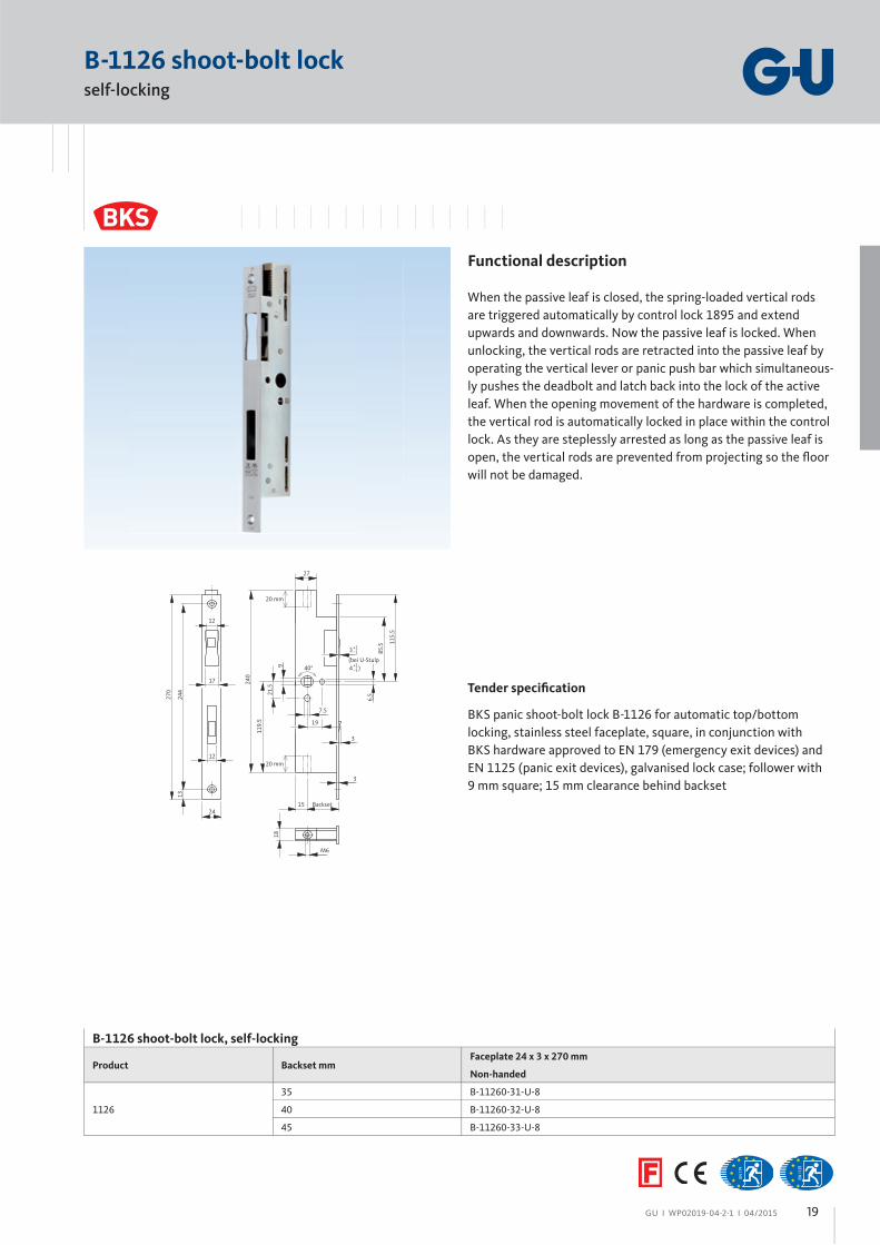
Functional description
When the passive leaf is closed, the spring-loaded vertical rods
are triggered automatically by control lock 1895 and extend
upwards and downwards. Now the passive leaf is locked. When
unlocking, the vertical rods are retracted into the passive leaf by
operating the vertical lever or panic push bar which simultaneous-
ly pushes the deadbolt and latch back into the lock of the active
leaf. When the opening movement of the hardware is completed,
the vertical rod is automatically locked in place within the control
lock. As they are steplessly arrested as long as the passive leaf is
open, the vertical rods are prevented from projecting so the fl oor
will not be damaged.
18
M6
270
1324
4
24
12
17
40°
20 mm
20 mm
119.
5
240
115.
5
85.5
3
7.5
9
15 Backset
6.521
.5
19
3
27
(bei U-Stulp 4 )+1
–1
3+1–1
12
Tender specifi cation
BKS panic shoot-bolt lock B-1126 for automatic top/bottom
locking, stainless steel faceplate, square, in conjunction with
BKS hardware approved to EN 179 (emergency exit devices) and
EN 1125 (panic exit devices), galvanised lock case; follower with
9 mm square; 15 mm clearance behind backset
B-1126 shoot-bolt lock, self-locking
Product Backset mmFaceplate 24 x 3 x 270 mm
Non-handed
1126
35 B-11260-31-U-8
40 B-11260-32-U-8
45 B-11260-33-U-8
19
Panic exit and emergency exit devices for narrow stile doors І Locks for single and double-leaf doors
GU І WP02019-04-2-1 І 04/2015
-1 mm
12
235.61
5.1 25.3
52
64
8.5
16
1211
3 6
61
03
001
15 24
061
21631
97
19
BacksetBackset
B 1316 latch lock for single-leaf doors
Product Backset mmFaceplate 24 x 3 x 160 mm U-faceplate 24 x 6 x 160 mm
DIN LH DIN RH DIN LH DIN RH
1316
35 B 1316 2003 B 1316 2004 B 1316 2023 B 1316 2024
40 B 1316 2005 B 1316 2006 B 1316 2025 B 1316 2026
45 B 1316 2007 B 1316 2008 B 1316 2027 B 1316 2028
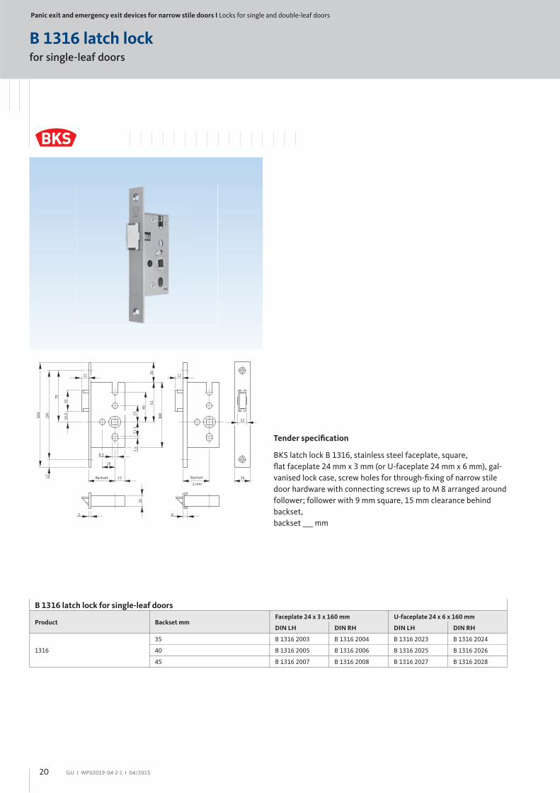
Tender specifi cation
BKS latch lock B 1316, stainless steel faceplate, square,
fl at faceplate 24 mm x 3 mm (or U-faceplate 24 mm x 6 mm), gal-
vanised lock case, screw holes for through-fi xing of narrow stile
door hardware with connecting screws up to M 8 arranged around
follower; follower with 9 mm square, 15 mm clearance behind
backset,
backset ___ mm
for single-leaf doors
B 1316 latch lock
20

GU І WP02019-04-2-1 І 04/2015 21
Panic exit and emergency exit devices for narrow stile doors І Strikers
GU І WP02019-04-2-1 І 04/2015
Striker
51.5
47
12
15
12
50
123
13
270
244
24
122
12
268
244
24
3
53.5
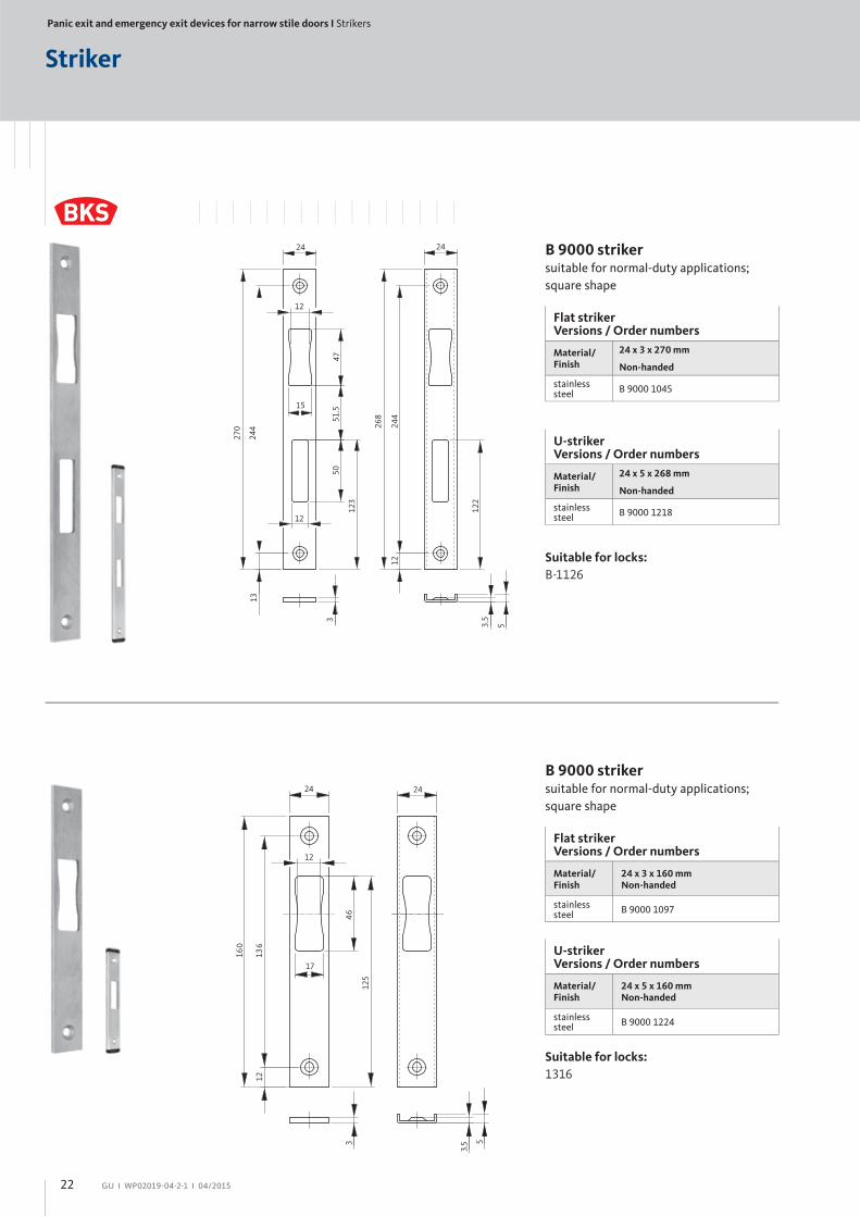
B 9000 striker suitable for normal-duty applications;
square shape
Suitable for locks:
B-1126
Flat striker Versions / Order numbers
Material/Finish
24 x 3 x 270 mm
Non-handed
stainlesssteel
B 9000 1045
U-striker Versions / Order numbers
Material/Finish
24 x 5 x 268 mm
Non-handed
stainlesssteel
B 9000 1218
B 9000 striker suitable for normal-duty applications;
square shape
Flat striker Versions / Order numbers
Material/Finish
24 x 3 x 160 mmNon-handed
stainlesssteel
B 9000 1097
21
160
24
5.3
24
3 5
521
46
316
17
12
Suitable for locks:
1316
U-striker Versions / Order numbers
Material/Finish
24 x 5 x 160 mmNon-handed
stainlesssteel
B 9000 1224
22

GU І WP02019-04-2-1 І 04/2015
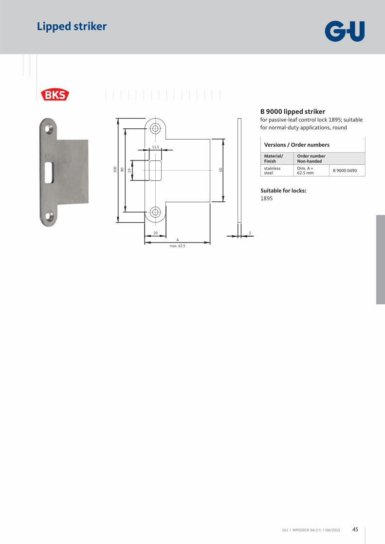
Lipped striker
Versions / Order numbers
Material/Finish
Order numberNon-handed
stainlesssteel
Dim. A = 62.5 mm
B 9000 0490
B 9000 lipped striker for passive-leaf control lock 1895; suitable
for normal-duty applications, round
Suitable for locks:
1895
80 19
A
20
11.5
60
3
100
max. 62.5
23
Panic exit and emergency exit devices for narrow stile doors І Door hardware to EN 1906, EN 179 and EN 1125
GU І WP02019-04-2-1 І 04/2015
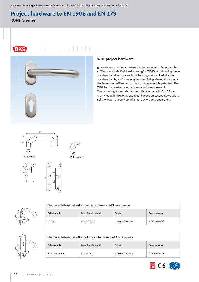
RONDO series
Project hardware to EN 1906 and EN 179
WDL project hardware
guarantees a maintenance-free bearing system for lever handles
(= "Wartungsfreie Drücker-Lagerung" = 'WDL'). Axial pulling forces
are absorbed due to a very large bearing surface. Radial forces
are absorbed by an 8 mm long, toothed fi xing element that holds
the lever; the resilient and robust fi xing element is patented. The
WDL bearing system also features a lubricant reservoir.
The mounting accessories for door thicknesses of 42 to 52 mm
are included in the items supplied. For use on escape doors with a
split follower, the split spindle must be ordered separately.
RONDO H1.1
70
151
53
Ø 21
K1.1 round knob
Ø 21
69
71
Narrow stile lever set with rosettes, for fi re-rated 9 mm spindle
Cylinder hole Lever handle model Colour Order number
PC - oval RONDO H1.1 stainless steel matt B-72030-01-0-8
Narrow stile lever set with backplates, for fi re-rated 9 mm spindle
Cylinder hole Lever handle model Colour Order number
PC 92 mm - round RONDO H1.1 stainless steel matt B-72040-61-0-8
32.7
70 50
9 32.7
252
21.5
135
85
9
Ø8
5
24

GU І WP02019-04-2-1 І 04/2015
Narrow stile half-set with lever handle and rosettes, for fi re-rated 9 mm spindle
Cylinder hole Lever handle model Colour Order number
PC - oval RONDO H1.1 stainless steel matt B-72130-01-0-8
Vertical lever RONDO H1.1 stainless steel matt B-72130-61-0-8
Narrow stile half-set with lever handle and backplate, for fi re-rated 9 mm spindle
Cylinder hole Lever handle model Colour Order number
PC 92 mm - round RONDO H1.1 stainless steel matt B-72140-61-0-8
Vertical lever RONDO H1.1 stainless steel matt B-72140-41-0-8
Narrow stile entrance set with rosettes, for fi re-rated 9 mm spindle
Cylinder hole Lever handle model Colour Order number
PC - oval RONDO H1.1 stainless steel matt B-72330-01-0-8
Narrow stile entrance set with backplates, for fi re-rated 9 mm spindle
Cylinder hole Lever handle model Colour Order number
PC 92 mm - round RONDO H1.1 stainless steel matt B-72340-61-0-8
Narrow stile half-set with rosette and knob
Cylinder hole Lever handle model Colour Order number
PC - oval K1.1 round knob stainless steel matt B-72630-01-0-8
Narrow stile half-set with backplate and knob
Cylinder hole Lever handle model Colour Order number
PC 92 mm - round K1.1 round knob stainless steel matt B-72640-61-0-8
25
Panic exit and emergency exit devices for narrow stile doors І Door hardware to EN 1906, EN 179 and EN 1125
GU І WP02019-04-2-1 І 04/2015
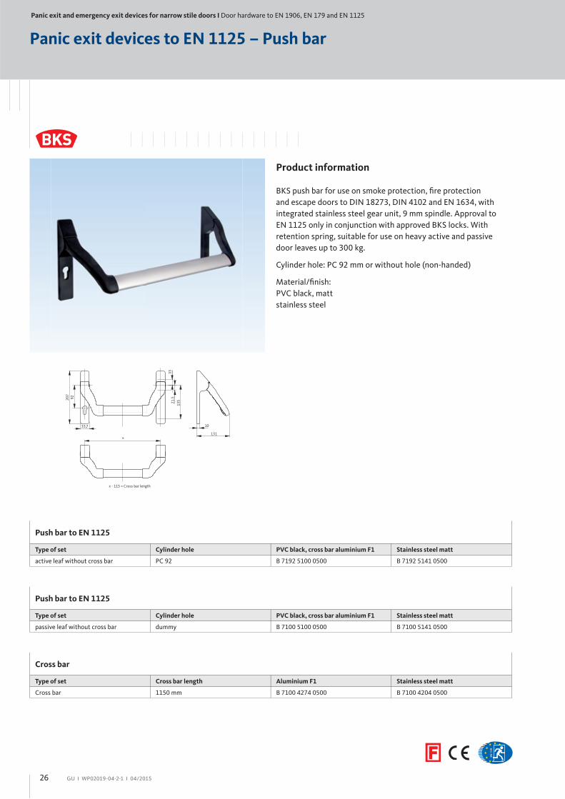
Panic exit devices to EN 1125 – Push bar
Product information
BKS push bar for use on smoke protection, fi re protection
and escape doors to DIN 18273, DIN 4102 and EN 1634, with
integrated stainless steel gear unit, 9 mm spindle. Approval to
EN 1125 only in conjunction with approved BKS locks. With
retention spring, suitable for use on heavy active and passive
door leaves up to 300 kg.
Cylinder hole: PC 92 mm or without hole (non-handed)
Material/fi nish:
PVC black, matt
stainless steel
92
x - 115 = Cross bar length
x131
10
33
207
33,7
21.5
135
Push bar to EN 1125
Type of set Cylinder hole PVC black, cross bar aluminium F1 Stainless steel matt
active leaf without cross bar PC 92 B 7192 5100 0500 B 7192 5141 0500
Push bar to EN 1125
Type of set Cylinder hole PVC black, cross bar aluminium F1 Stainless steel matt
passive leaf without cross bar dummy B 7100 5100 0500 B 7100 5141 0500
Cross bar
Type of set Cross bar length Aluminium F1 Stainless steel matt
Cross bar 1150 mm B 7100 4274 0500 B 7100 4204 0500
26
Panic exit and emergency exit devices for narrow stile doors І Door hardware to EN 1906, EN 179 and EN 1125
GU І WP02019-04-2-1 І 04/2015
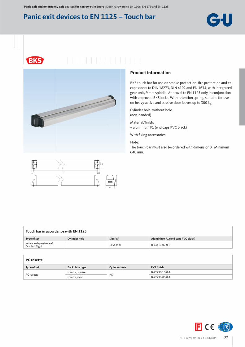
Panic exit devices to EN 1125 – Touch bar
Product information
BKS touch bar for use on smoke protection, fi re protection and es-
cape doors to DIN 18273, DIN 4102 and EN 1634, with integrated
gear unit, 9 mm spindle. Approval to EN 1125 only in conjunction
with approved BKS locks. With retention spring, suitable for use
on heavy active and passive door leaves up to 300 kg.
Cylinder hole: without hole
(non-handed)
Material/fi nish:
– aluminium F1 (end caps PVC black)
With fi xing accessories
Note:
The touch bar must also be ordered with dimension X. Minimum
640 mm.
X
43 66
15.5
81
99.5
15.5
Touch bar in accordance with EN 1125
Type of set Cylinder hole Dim "x" Aluminium F1 (end caps PVC black)
active leaf/passive leafDIN left/right
– 1158 mm B-74410-02-0-6
PC rosette
Type of set Backplate type Cylinder hole EV1 fi nish
PC rosetterosette, square
PCB-72730-10-0-1
rosette, oval B-72730-00-0-1
27
GU І WP02019-04-2-1 І 04/2015
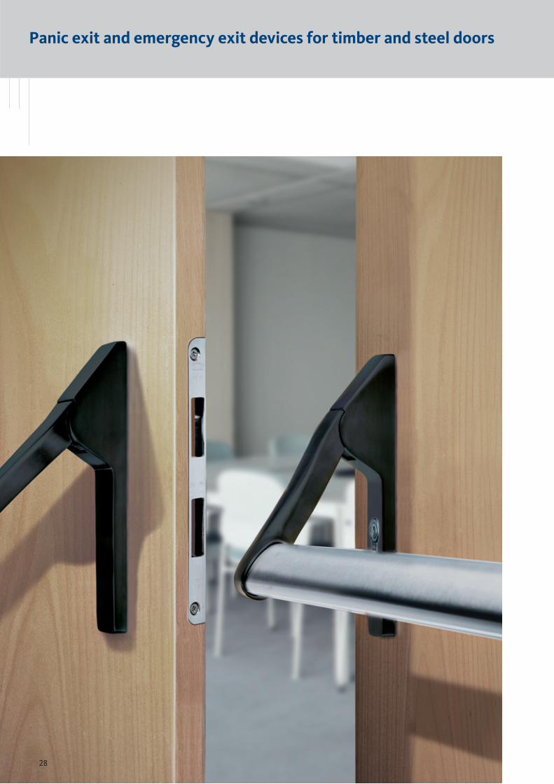
Panic exit and emergency exit devices for timber and steel doors
28
Panic exit and emergency exit devices for timber and steel doors
GU І WP02019-04-2-1 І 04/2015
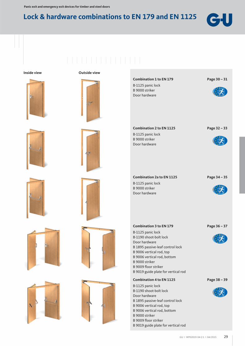
Lock & hardware combinations to EN 179 and EN 1125
Inside view Outside view
Combination 1 to EN 179 Page 30 – 31
B-1125 panic lock
B 9000 striker
Door hardware
Combination 2 to EN 1125 Page 32 – 33
B-1125 panic lock
B 9000 striker
Door hardware
Combination 2a to EN 1125 Page 34 – 35
B-1125 panic lock
B 9000 striker
Door hardware
Combination 3 to EN 179 Page 36 – 37
B-1125 panic lock
B-1190 shoot-bolt lock
Door hardware
B 1895 passive-leaf control lock
B 9006 vertical rod, top
B 9006 vertical rod, bottom
B 9000 striker
B 9009 fl oor striker
B 9019 guide plate for vertical rod
Combination 4 to EN 1125 Page 38 – 39
B-1125 panic lock
B-1190 shoot-bolt lock
Door hardware
B 1895 passive-leaf control lock
B 9006 vertical rod, top
B 9006 vertical rod, bottom
B 9000 striker
B 9009 fl oor striker
B 9019 guide plate for vertical rod
29

Panic exit and emergency exit devices for timber and steel doors І Lock & hardware combinations to EN 179 and EN 1125
GU І WP02019-04-2-1 І 04/2015
Functional descriptionInside
The door can be opened at any time using the lever handle (panic
function). With series B-1125, locking is done by key. To ensure
proper panic release, the key should always be withdrawn.
Panic function B
Panic function E
Outside
The door leaf is opened using the key and lever handle (panic
function B). The door can only be unlocked by key (panic
function E, e.g. with a fi xed knob on the outside).
With series B-1125, locking is done by key.
Possible applications• Emergency exits to EN 179 in non-public areas
• Suitable for fi re and smoke control doors
• Due to the external lever handle, use as entrance door or
connecting door is possible from both sides depending on
the particular panic function
Recommendation• Hallway doors in offi ce buildings
• Homes for the elderly
• Secondary entrance doors
• Secondary entrance doors in kindergartens, schools and
hotels
Inside view Outside view
Combination 1 to EN 179Panic function, single-leaf
30

GU І WP02019-04-2-1 І 04/2015
Combination 1 to EN 179Panic function, single-leaf
Active leaf
No. Product / FunctionBacksetin mm
Faceplate 24 x 3 x 235 mmsee page
Non-handed
1
1125 /Panic function E
65
B-11259-01-U-2 41
1125 /Panic function B
B-11259-02-U-2 41
1125 /Panic function E
B-11259-03-U-2 42
1125 /Panic function B
B-11259-04-U-2 42
2
1
Active leaf:
= Panic lock
= Striker
= Door closer
1
2
Frame
No. ProductFaceplate shape
see page
2 Lipped strikerround B 9000 0810 44
square B 9000 0775 44
3 For door closers refer to our catalogue WP00600-04-2-1
Door hardware to EN 179
Short backplate, black PVC
Product see page
Lever set, panic function B B 7123 0000 47
Panic function E B 7123 0010 47
3
3
31

Panic exit and emergency exit devices for timber and steel doors І Lock & hardware combinations to EN 179 and EN 1125
GU І WP02019-04-2-1 І 04/2015
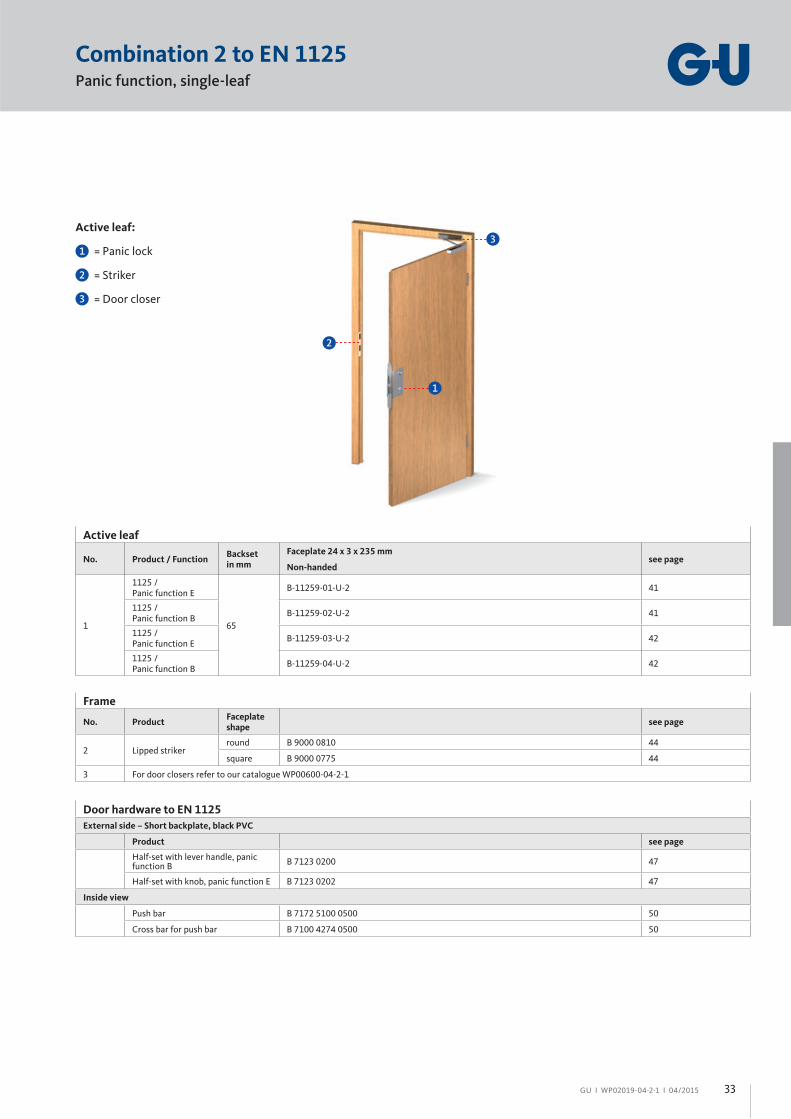
Combination 2 to EN 1125Panic function, single-leaf
Inside view Outside view
Functional descriptionInside
The door can be opened by the push bar at any time (panic func-
tion). With series B-1125, locking is done by key. To ensure proper
panic release, the key should always be withdrawn.
Panic function B
Panic function E
Outside
The door leaf is opened using the key and lever handle (panic
function B). The door can only be unlocked by key (panic
function E, e.g. with a fi xed knob on the outside).
With series B-1125, locking is done by key.
Possible applications• Escape doors to EN 1125 in public facilities
• Suitable for fi re and smoke control doors
• With the fi xed knob/pull handle on the outside, access is
only possible by key.
Recommendation• Doors on transformer stations and boiler rooms
• Lift shafts
• Underground carparks
• Entrance to stores and business houses
• Homes for the elderly and senior residences
32
GU І WP02019-04-2-1 І 04/2015
Combination 2 to EN 1125Panic function, single-leaf
Active leaf:
= Panic lock
= Striker
= Door closer
1
2
2
1
Door hardware to EN 1125
External side – Short backplate, black PVC
Product see page
Half-set with lever handle, panic function B
B 7123 0200 47
Half-set with knob, panic function E B 7123 0202 47
Inside view
Push bar B 7172 5100 0500 50
Cross bar for push bar B 7100 4274 0500 50
Frame
No. ProductFaceplate shape
see page
2 Lipped strikerround B 9000 0810 44
square B 9000 0775 44
3 For door closers refer to our catalogue WP00600-04-2-1
Active leaf
No. Product / FunctionBacksetin mm
Faceplate 24 x 3 x 235 mmsee page
Non-handed
1
1125 /Panic function E
65
B-11259-01-U-2 41
1125 /Panic function B
B-11259-02-U-2 41
1125 /Panic function E
B-11259-03-U-2 42
1125 /Panic function B
B-11259-04-U-2 42
3
3
33

Panic exit and emergency exit devices for timber and steel doors І Lock & hardware combinations to EN 179 and EN 1125
GU І WP02019-04-2-1 І 04/2015
Combination 2a to EN 1125Panic function, single-leaf
Inside view Outside view
Functional descriptionInside
The door can be opened by the push bar at any time (panic func-
tion).
Possible applications• Escape doors to EN 1125 in public facilities
• Suitable for fi re and smoke control doors
34

GU І WP02019-04-2-1 І 04/2015
Combination 2a to EN 1125Panic function, single-leaf
Active leaf:
= Panic lock
= Striker
= Door closer
1
2
2
1
Door hardware to EN 1125
Inside view
Product see page
Push bar B 7100 5100 0500 50
Cross bar for push bar B 7100 4274 0500 50
Frame
No. ProductFaceplate shape
see page
2 Lipped strikerround B 9000 0810 44
square B 9000 0775 44
3 For door closers refer to our catalogue WP00600-04-2-1
Active leaf
No. Product / FunctionBacksetin mm
Faceplate 24 x 3 x 235 mmsee page
Non-handed
11125 /Panic function E
65 B-11259-01-U-2 41
3
3
35
Panic exit and emergency exit devices for timber and steel doors І Lock & hardware combinations to EN 179 and EN 1125
GU І WP02019-04-2-1 І 04/2015
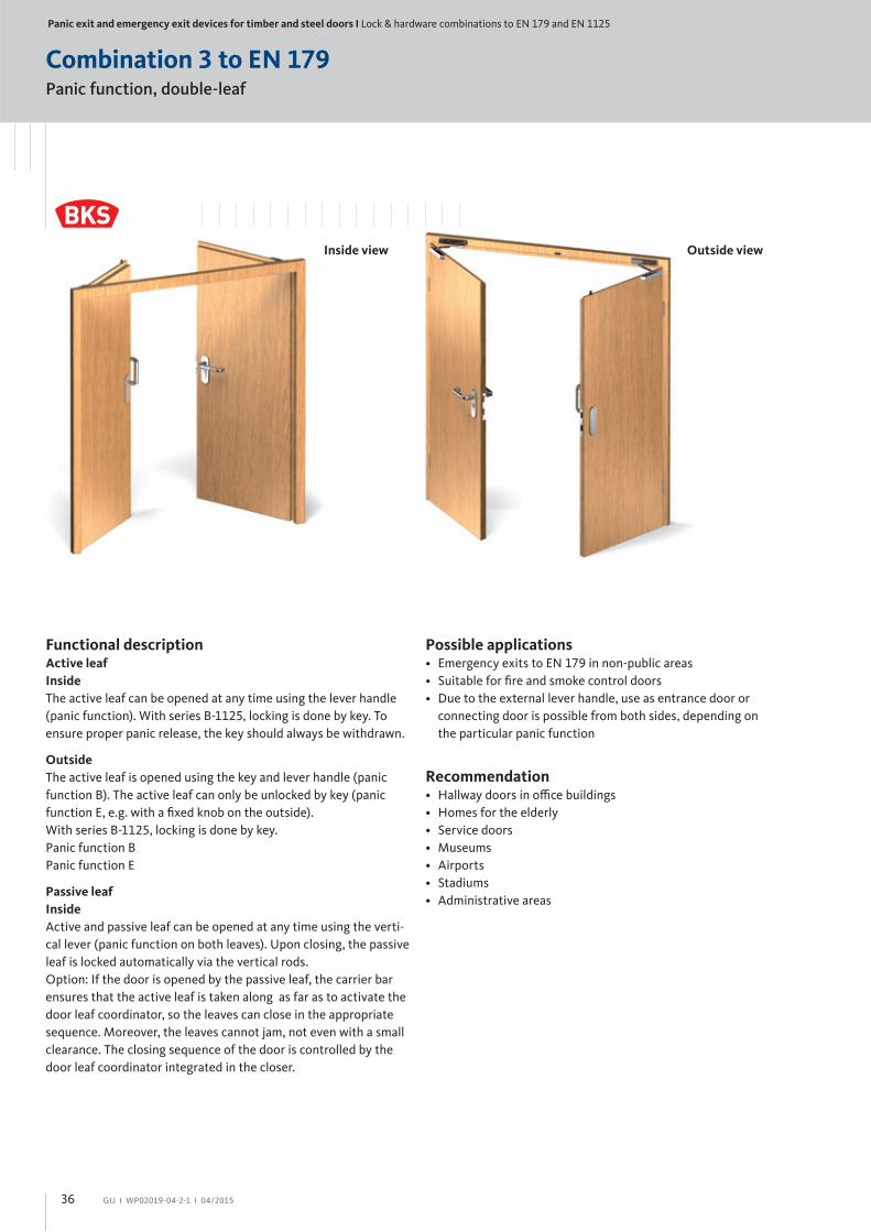
Combination 3 to EN 179Panic function, double-leaf
Inside view Outside view
Functional descriptionActive leaf
Inside
The active leaf can be opened at any time using the lever handle
(panic function). With series B-1125, locking is done by key. To
ensure proper panic release, the key should always be withdrawn.
Outside
The active leaf is opened using the key and lever handle (panic
function B). The active leaf can only be unlocked by key (panic
function E, e.g. with a fi xed knob on the outside).
With series B-1125, locking is done by key.
Panic function B
Panic function E
Passive leaf
Inside
Active and passive leaf can be opened at any time using the verti-
cal lever (panic function on both leaves). Upon closing, the passive
leaf is locked automatically via the vertical rods.
Option: If the door is opened by the passive leaf, the carrier bar
ensures that the active leaf is taken along as far as to activate the
door leaf coordinator, so the leaves can close in the appropriate
sequence. Moreover, the leaves cannot jam, not even with a small
clearance. The closing sequence of the door is controlled by the
door leaf coordinator integrated in the closer.
Possible applications• Emergency exits to EN 179 in non-public areas
• Suitable for fi re and smoke control doors
• Due to the external lever handle, use as entrance door or
connecting door is possible from both sides, depending on
the particular panic function
Recommendation• Hallway doors in offi ce buildings
• Homes for the elderly
• Service doors
• Museums
• Airports
• Stadiums
• Administrative areas
36

GU І WP02019-04-2-1 І 04/2015
Combination 3 to EN 179Panic function, double-leaf
Passive leaf:
= Shoot-bolt lock
= Control lock
= Vertical rod
= Solid vertical rod
= Striker
= Floor striker
= Guide plate for vertical rod
= Door closer
2
3
4
5
6
7
8
Active leaf:
= Panic lock
= Door closer
1
7
8
3
4
2
5
1
6
Passive leaf
No. ProductBacksetin mm
Faceplate 24 x 3 x 235 mmsee page
Non-handed
2 1190 65 B-11900-00-0-2 43
3 1895 65 B 1895 0003 0500 52
4 9006 with end plug B 9006 0013 0500 52
5 9006 solid B 9006 0004 0500 53
6 9000 for 9006 B 9000 0490 45
7 9009 – B 9009 0001 0500 53
8 9019 – B 9019 0001 0500 54
9 For door closers refer to our catalogue WP00600-04-2-1
Door hardware to EN 179
Short backplate, black PVC
Product see page
Lever set, panic function B B 7123 0000 47
Panic function E B 7123 0010 47
Vertical lever B 7123 0201 47
Active leaf
No. Product / FunctionBacksetin mm
Faceplate 24 x 3 x 235 mmsee page
Non-handed
1
1125 /Panic function E
65
B-11259-01-U-2 41
1125 /Panic function B
B-11259-02-U-2 41
9
9
9
9
37

Panic exit and emergency exit devices for timber and steel doors І Lock & hardware combinations to EN 179 and EN 1125
GU І WP02019-04-2-1 І 04/2015
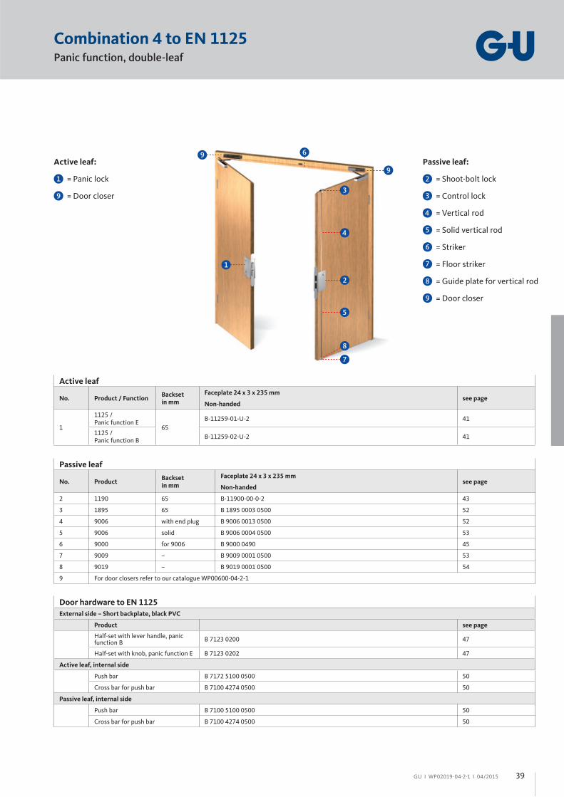
Combination 4 to EN 1125Panic function, double-leaf
Inside view Outside view
Functional descriptionActive leaf
Inside
The active leaf can be opened at any time using the lever handle
(panic function). With series B-1125, locking is done by key. To
ensure proper panic release, the key should always be withdrawn.
Outside
The active leaf is opened using the key and lever handle (panic
function B). The active leaf can only be unlocked by key (panic
function E, e.g. with a fi xed knob on the outside).
With series B-1125, locking is done by key.
Panic function B
Panic function E
Passive leaf
Inside
Active and passive leaf can be opened at any time using the verti-
cal lever (panic function on both leaves). Upon closing, the passive
leaf is locked automatically via the vertical rods.
Option: If the door is opened by the passive leaf, the carrier bar
ensures that the active leaf is taken along as far as to activate the
door leaf coordinator, so the leaves can close in the appropriate
sequence. Moreover, the leaves cannot jam, not even with a small
clearance. The closing sequence of the door is controlled by the
door leaf coordinator integrated in the closer.
Possible applications• Escape doors to EN 1125 in public facilities
• Suitable for fi re and smoke control doors
• With the fi xed knob/pull handle on the outside, access is
only possible by key.
• Optional combination with electric access control and/or
escape door security components
Recommendation• Shopping centres
• Airports
• Stadiums
• Entry halls and foyers
• Schools and universities
• Hospitals
38
GU І WP02019-04-2-1 І 04/2015
Combination 4 to EN 1125Panic function, double-leaf
Passive leaf:
= Shoot-bolt lock
= Control lock
= Vertical rod
= Solid vertical rod
= Striker
= Floor striker
= Guide plate for vertical rod
= Door closer
2
3
4
5
6
7
8
Active leaf:
= Panic lock
= Door closer
1
7
8
3
4
2
5
1
6
Passive leaf
No. ProductBacksetin mm
Faceplate 24 x 3 x 235 mmsee page
Non-handed
2 1190 65 B-11900-00-0-2 43
3 1895 65 B 1895 0003 0500 52
4 9006 with end plug B 9006 0013 0500 52
5 9006 solid B 9006 0004 0500 53
6 9000 for 9006 B 9000 0490 45
7 9009 – B 9009 0001 0500 53
8 9019 – B 9019 0001 0500 54
9 For door closers refer to our catalogue WP00600-04-2-1
Door hardware to EN 1125
External side – Short backplate, black PVC
Product see page
Half-set with lever handle, panic function B
B 7123 0200 47
Half-set with knob, panic function E B 7123 0202 47
Active leaf, internal side
Push bar B 7172 5100 0500 50
Cross bar for push bar B 7100 4274 0500 50
Passive leaf, internal side
Push bar B 7100 5100 0500 50
Cross bar for push bar B 7100 4274 0500 50
Active leaf
No. Product / FunctionBacksetin mm
Faceplate 24 x 3 x 235 mmsee page
Non-handed
1
1125 /Panic function E
65
B-11259-01-U-2 41
1125 /Panic function B
B-11259-02-U-2 41
9
9
9
9
39
Panic exit and emergency exit devices for timber and steel doors І Locks for single and double-leaf doors
GU І WP02019-04-2-1 І 04/2015
as single-latch lock for single-leaf doors
B-1125 fi re protection door lock27
14.5
19.565
84.5
1
16
1
235
1320
9
14
24
186
37.5
72
7262
24.5
3
9
45
5
7
Tender specifi cation
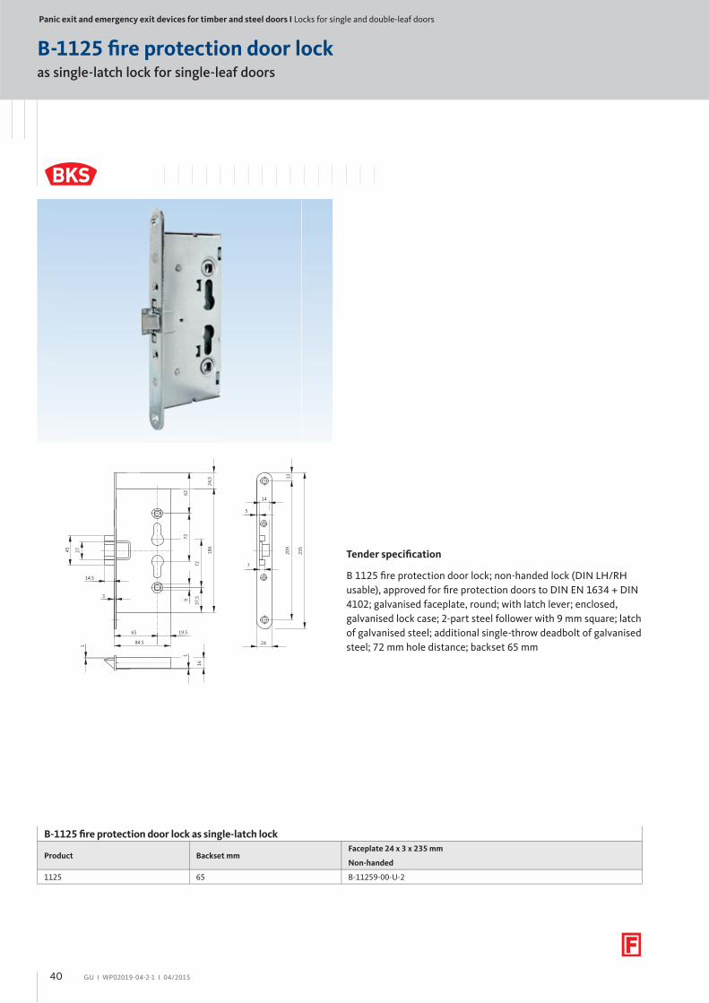
B 1125 fi re protection door lock; non-handed lock (DIN LH/RH
usable), approved for fi re protection doors to DIN EN 1634 + DIN
4102; galvanised faceplate, round; with latch lever; enclosed,
galvanised lock case; 2-part steel follower with 9 mm square; latch
of galvanised steel; additional single-throw deadbolt of galvanised
steel; 72 mm hole distance; backset 65 mm
B-1125 fi re protection door lock as single-latch lock
Product Backset mmFaceplate 24 x 3 x 235 mm
Non-handed
1125 65 B-11259-00-U-2
40
GU І WP02019-04-2-1 І 04/2015
as single-latch lock for single and double-leaf doors
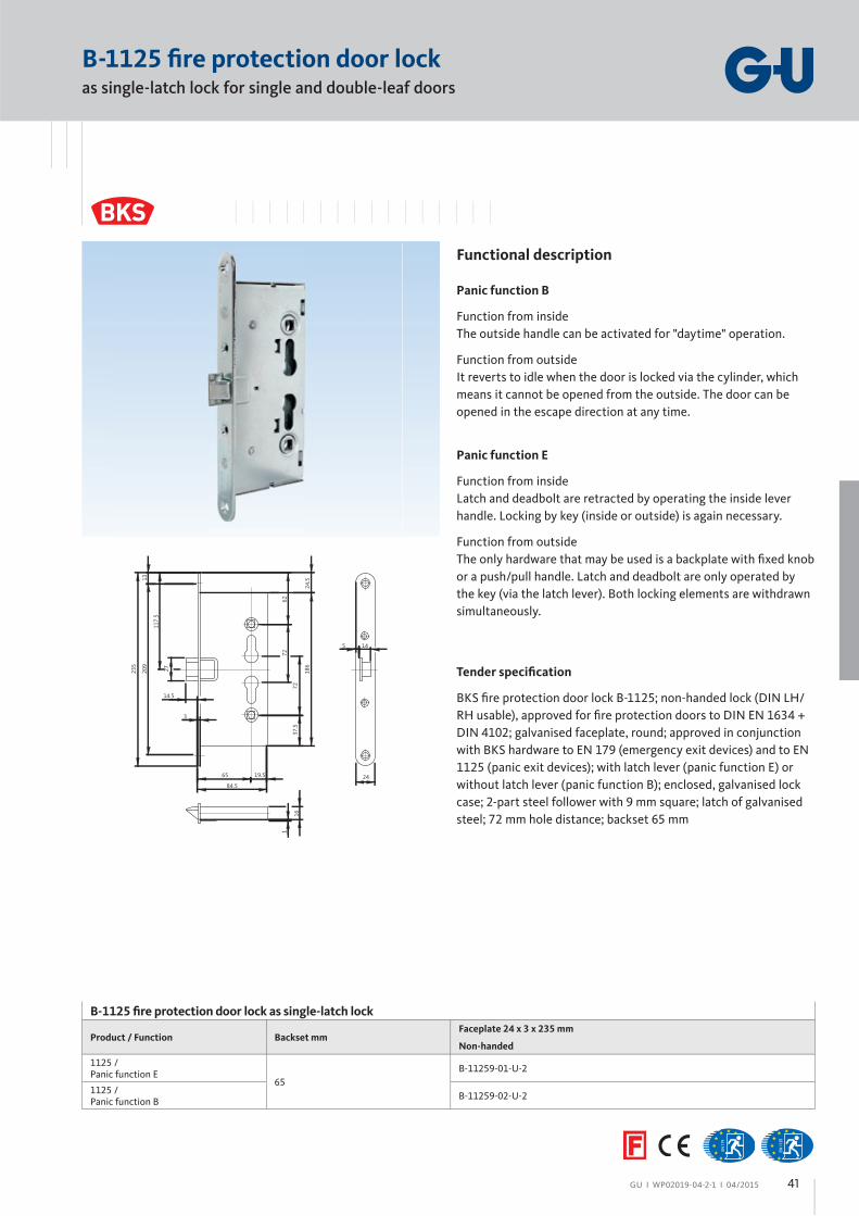
B-1125 fi re protection door lock
Functional description
Panic function B
Function from inside
The outside handle can be activated for "daytime" operation.
Function from outside
It reverts to idle when the door is locked via the cylinder, which
means it cannot be opened from the outside. The door can be
opened in the escape direction at any time.
Panic function E
Function from inside
Latch and deadbolt are retracted by operating the inside lever
handle. Locking by key (inside or outside) is again necessary.
Function from outside
The only hardware that may be used is a backplate with fi xed knob
or a push/pull handle. Latch and deadbolt are only operated by
the key (via the latch lever). Both locking elements are withdrawn
simultaneously.
117.
5
235
27
1320
9
14.5
65
3
84.5
19.5
7262
7237
.5
186
24.5
145
24
1
16
Tender specifi cation
BKS fi re protection door lock B-1125; non-handed lock (DIN LH/
RH usable), approved for fi re protection doors to DIN EN 1634 +
DIN 4102; galvanised faceplate, round; approved in conjunction
with BKS hardware to EN 179 (emergency exit devices) and to EN
1125 (panic exit devices); with latch lever (panic function E) or
without latch lever (panic function B); enclosed, galvanised lock
case; 2-part steel follower with 9 mm square; latch of galvanised
steel; 72 mm hole distance; backset 65 mm
B-1125 fi re protection door lock as single-latch lock
Product / Function Backset mmFaceplate 24 x 3 x 235 mm
Non-handed
1125 /Panic function E
65
B-11259-01-U-2
1125 /Panic function B
B-11259-02-U-2
41

Panic exit and emergency exit devices for timber and steel doors І Locks for single and double-leaf doors
GU І WP02019-04-2-1 І 04/2015
as single-latch lock for single-leaf doors
B-1125 fi re protection door lock
Functional description
Panic function B
Function from inside
The outside handle can be activated for "daytime" operation.
Function from outside
It reverts to idle when the door is locked via the cylinder, which
means it cannot be opened from the outside. The door can be
opened in the escape direction at any time.
Panic function E
Function from inside
Latch and deadbolt are retracted by operating the inside lever
handle. Locking by key (inside or outside) is again necessary.
Function from outside
The only hardware that may be used is a backplate with fi xed knob
or a push/pull handle. Latch and deadbolt are only operated by
the key (via the latch lever). Both locking elements are withdrawn
simultaneously.
27
14.5
19.565
84.5
1
16
1
235
1320
9
14
24
186
37.5
72
7262
24.5
3
9
45
5
7
Tender specifi cation
BKS fi re protection door lock B-1125; non-handed lock (DIN LH/
RH usable), approved for fi re protection doors to DIN EN 1634 +
DIN 4102; galvanised faceplate, round; approved in conjunction
with BKS hardware to EN 179 (emergency exit devices) and to
EN 1125 (panic exit devices); with latch lever (panic function E) or
without latch lever (panic function B); enclosed, galvanised lock
case; 2-part steel follower with 9 mm square; latch of galvanised
steel; 72 mm hole distance; backset 65 mm
B-1125 fi re protection door lock as single-latch lock
Product Backset mmFaceplate 24 x 3 x 235 mm
Non-handed
1125 /Panic function E
65
B-11259-03-U-2
1125 /Panic function B
B-11259-04-U-2
42
GU І WP02019-04-2-1 І 04/2015
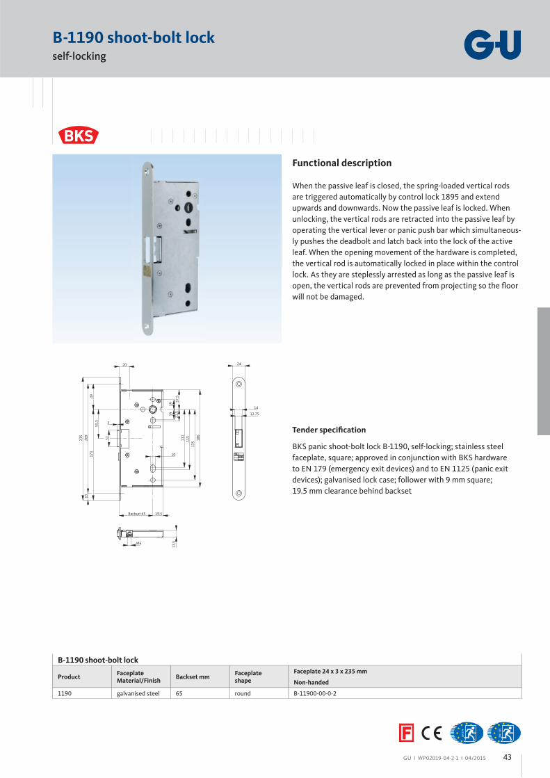
B-1190 shoot-bolt lock
B-1190 shoot-bolt lock
ProductFaceplateMaterial/Finish
Backset mmFaceplateshape
Faceplate 24 x 3 x 235 mm
Non-handed
1190 galvanised steel 65 round B-11900-00-0-2
24
3
235
209
1317
349
1919 21
.5
111
115
135
37.5
186
10
Backset 65 19.5
12.75
14
20
M6
13.5
32
55.5
Functional description
When the passive leaf is closed, the spring-loaded vertical rods
are triggered automatically by control lock 1895 and extend
upwards and downwards. Now the passive leaf is locked. When
unlocking, the vertical rods are retracted into the passive leaf by
operating the vertical lever or panic push bar which simultaneous-
ly pushes the deadbolt and latch back into the lock of the active
leaf. When the opening movement of the hardware is completed,
the vertical rod is automatically locked in place within the control
lock. As they are steplessly arrested as long as the passive leaf is
open, the vertical rods are prevented from projecting so the fl oor
will not be damaged.
Tender specifi cation
BKS panic shoot-bolt lock B-1190, self-locking; stainless steel
faceplate, square; approved in conjunction with BKS hardware
to EN 179 (emergency exit devices) and to EN 1125 (panic exit
devices); galvanised lock case; follower with 9 mm square;
19.5 mm clearance behind backset
self-locking
43
Panic exit and emergency exit devices for timber and steel doors І Strikers
GU І WP02019-04-2-1 І 04/2015
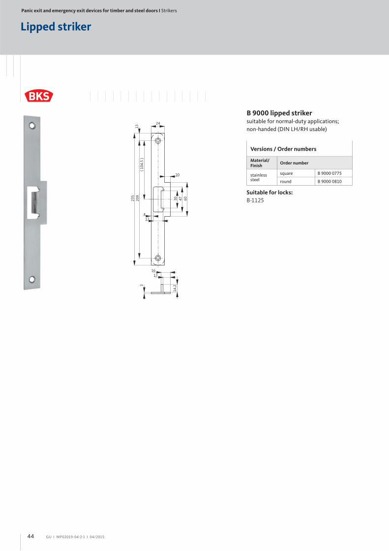
Lipped striker
B 9000 lipped striker suitable for normal-duty applications;
non-handed (DIN LH/RH usable)
Suitable for locks:
B-1125
Versions / Order numbers
Material/Finish
Order number
stainlesssteel
square B 9000 0775
round B 9000 0810
24
10
60235
174
30 47
3( 1
04.5
)13
209
1316
14.2
44
GU І WP02019-04-2-1 І 04/2015
Lipped striker
Versions / Order numbers
Material/Finish
Order numberNon-handed
stainlesssteel
Dim. A = 62.5 mm
B 9000 0490
B 9000 lipped striker for passive-leaf control lock 1895; suitable
for normal-duty applications, round
Suitable for locks:
1895
80 19
A
20
11.5
60
3
100
max. 62.5
45
Panic exit and emergency exit devices for timber and steel doors І Door hardware to EN 1906, EN 179 and EN 1125
GU І WP02019-04-2-1 І 04/2015
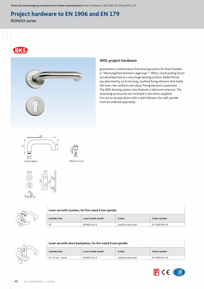
RONDO series
Fire protection hardware to EN 1906 and EN 179
Fire protection hardware
with steel base, fi xed backplate with friction washer. Mounting
accessories and spindle for door thicknesses of 40 to 60 mm are
included in the items supplied.
For use on escape doors with a split follower, the split spindle
must be ordered separately.
RONDO H1.0
70
145
Ø 21
53
K1.0 round knob
Ø 21
57
Ø 50
45
161 21
.511
2
9
5
Ø8
46
GU І WP02019-04-2-1 І 04/2015
Half-set with lever handle and short backplate, for fi re-rated 9 mm spindle
Cylinder hole Lever handle model Colour Order number
PC 72 mm - square RONDO H1.0 PVC black B 7123 0200
Vertical lever RONDO H1.0 PVC black B 7123 0201
Entrance set with short backplates, for fi re-rated 9 mm spindle
Cylinder hole Lever handle model Colour Order number
PC 72 mm - square K1.0 round knob PVC black B 7123 0010
Half-set with short backplate and knob
Cylinder hole Lever handle model Colour Order number
PC 72 mm - square K1.0 round knob PVC black B 7123 0202
Lever set with short backplates, for fi re-rated 9 mm spindle
Cylinder hole Lever handle model Colour Order number
PC 72 mm - square RONDO H1.0 PVC black B 7123 0000
47
Panic exit and emergency exit devices for timber and steel doors І Door hardware to EN 1906, EN 179 and EN 1125
GU І WP02019-04-2-1 І 04/2015
RONDO series
Project hardware to EN 1906 and EN 179
WDL project hardware
guarantees a maintenance-free bearing system for lever handles
(= "Wartungsfreie Drücker-Lagerung" = 'WDL'). Axial pulling forces
are absorbed due to a very large bearing surface. Radial forces
are absorbed by an 8 mm long, toothed fi xing element that holds
the lever; the resilient and robust fi xing element is patented.
The WDL bearing system also features a lubricant reservoir. The
mounting accessories are included in the items supplied.
For use on escape doors with a split follower, the split spindle
must be ordered separately.
RONDO H1.0
70
145
Ø 21
53
K1.0 round knob
Ø 21
57
Ø 50
Lever set with rosettes, for fi re-rated 9 mm spindle
Cylinder hole Lever handle model Colour Order number
PC RONDO H1.0 stainless steel matt B-72000-00-0-8
Lever set with short backplates, for fi re-rated 9 mm spindle
Cylinder hole Lever handle model Colour Order number
PC 72 mm - round RONDO H1.0 stainless steel matt B-72040-61-0-8
45
167 21
.511
2
9
5
Ø8
Ø55
9
Ø8
5
38
48
GU І WP02019-04-2-1 І 04/2015
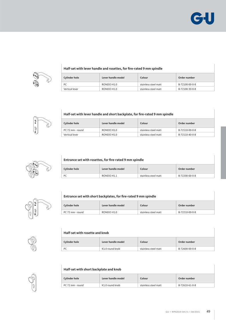
Half-set with lever handle and rosettes, for fi re-rated 9 mm spindle
Cylinder hole Lever handle model Colour Order number
PC RONDO H1.0 stainless steel matt B-72100-00-0-8
Vertical lever RONDO H1.0 stainless steel matt B-72100-30-0-8
Half-set with lever handle and short backplate, for fi re-rated 9 mm spindle
Cylinder hole Lever handle model Colour Order number
PC 72 mm - round RONDO H1.0 stainless steel matt B-72110-00-0-8
Vertical lever RONDO H1.0 stainless steel matt B-72110-40-0-8
Entrance set with rosettes, for fi re-rated 9 mm spindle
Cylinder hole Lever handle model Colour Order number
PC RONDO H1.1 stainless steel matt B-72200-00-0-8
Entrance set with short backplates, for fi re-rated 9 mm spindle
Cylinder hole Lever handle model Colour Order number
PC 72 mm - round RONDO H1.0 stainless steel matt B-72210-00-0-8
Half-set with rosette and knob
Cylinder hole Lever handle model Colour Order number
PC K1.0 round knob stainless steel matt B-72600-00-0-8
Half-set with short backplate and knob
Cylinder hole Lever handle model Colour Order number
PC 72 mm - round K1.0 round knob stainless steel matt B-72610-61-0-8
49

Panic exit and emergency exit devices for timber and steel doors І Door hardware to EN 1906, EN 179 and EN 1125
GU І WP02019-04-2-1 І 04/2015
Panic exit devices to EN 1125 – Push bar
Product information
BKS push bar for use on smoke protection, fi re protection
and escape doors to DIN 18273, DIN 4102 and EN 1634, with
integrated stainless steel gear unit, 9 mm spindle. Approval to
EN 1125 only in conjunction with approved BKS locks. With
retention spring, suitable for use on heavy active and passive
door leaves up to 300 kg.
Cylinder hole: PC 72 mm or
without hole (non-handed)
Material/fi nish:
PVC black, matt
stainless steel
72
x - 115 = Cross bar length
x131
10
33
207
33,7
21.5
112
Push bar to EN 1125
Type of set Cylinder hole PVC black, cross bar aluminium F1 Stainless steel matt
active leaf without cross bar PC 72 B 7172 5100 0500 B 7172 5141 0500
Push bar to EN 1125
Type of set Cylinder hole PVC black, cross bar aluminium F1 Stainless steel matt
passive leaf without cross bar dummy B 7100 5100 0500 B 7100 5141 0500
Cross bar
Type of set Cross bar length Aluminium F1 Stainless steel matt
Cross bar 1150 mm B 7100 4274 0500 B 7100 4204 0500
50
GU І WP02019-04-2-1 І 04/2015
Panic exit devices to EN 1125 – Touch bar
Product information
BKS touch bar for use on smoke protection, fi re protection and es-
cape doors to DIN 18273, DIN 4102 and EN 1634, with integrated
gear unit, 9 mm spindle. Approval to EN 1125 only in conjunction
with approved BKS locks. With retention spring, suitable for use
on heavy active and passive door leaves up to 300 kg.
Cylinder hole: without hole
(non-handed)
Material/fi nish:
– aluminium F1 (end caps PVC black)
With fi xing accessories
Note:
The touch bar must also be ordered with dimension X. Minimum
640 mm.
X
43 66
15.5
81
99.5
15.5
Touch bar in accordance with EN 1125
Type of set Cylinder hole Dim "x" Aluminium F1 (end caps PVC black)
active leaf/passive leafDIN left/right
– 1158 mm B-74410-02-0-6
51
Accessories І Miscellaneous
GU І WP02019-04-2-1 І 04/2015
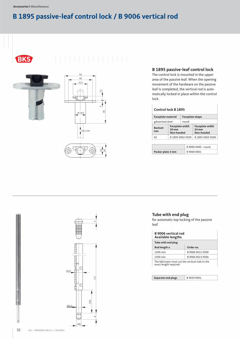
B 1895 passive-leaf control lock / B 9006 vertical rod
18.5 mm
403
Ø 18.5
7.5
25.5
54
42
2414
B 1895 passive-leaf control lockThe control lock is mounted in the upper
area of the passive leaf. When the opening
movement of the hardware on the passive
leaf is completed, the vertical rod is auto-
matically locked in place within the control
lock.
Control lock B 1895
Faceplate material Faceplate shape
galvanised steel round
Backsetmm
Faceplate width 20 mmNon-handed
Faceplate width 24 mm Non-handed
65 B 1895 0002 0500 B 1895 0003 0500
B 9000 0490 - round
Packer plate 3 mm B 9068 0001
Tube with end plug for automatic top locking of the passive
leaf
B 9006 vertical rodAvailable lengths
Tube with end plug
Rod length a Order no.
1200 mm B 9006 0012 0500
1500 mm B 9006 0013 0500
The fabricator must cut the vertical rods to the exact length required.
M6
8-2a
(30)
6.5
10
5
Ø
Ø
Separate end plugs B 9039 0001
52

GU І WP02019-04-2-1 І 04/2015
B 9006 vertical rod / B 9009 fl oor striker
Solid vertical rod Manual locking of the passive leaf at the
top, manual or automatic locking of the
passive leaf at the bottom.
B 9006 vertical rodAvailable lengths
Solid vertical rod
Rod length a Order no.
1187 mm B 9006 0004 0500
The fabricator must cut the vertical rods to the exact length required.
Ø 10
-2a
M6
Ø 9
825
B 9009 fl oor striker Functioning
The conical shape of the striker recess al-
lows a certain tolerance up to the end stop.
The continuous folded edge sits fl ush with
the fl oor. The larger bearing surface must
face in the opening direction to prevent the
fl oor being damaged by the vertical rod.
Floor striker
Dimension Order no.
100 x 56 x 20 mm B 9009 0001 0500
20 4
Ø 14
Ø 6
90°
10080
569
33
20601432
1516
56
53
Accessories І Miscellaneous
GU І WP02019-04-2-1 І 04/2015
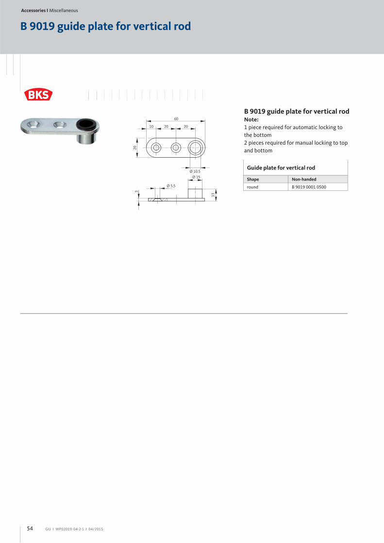
B 9019 guide plate for vertical rod
B 9019 guide plate for vertical rod Note:
1 piece required for automatic locking to
the bottom
2 pieces required for manual locking to top
and bottom
Guide plate for vertical rod
Shape Non-handed
round B 9019 0001 0500
20
10 20 20
Ø 10.5
60
Ø 15
13
3
Ø 5.5
54

Accessories І Square spindles / Screws
GU І WP02019-04-2-1 І 04/2015
Spindle / Entrance set spindle
L
min. 25max. 35
min. 25max. 35
B-7840 spindleDetermining
the spindle length
B-7841 entrance set spindleDetermining
the spindle length
Versions / Order numbers
Spindle Order number*
9 mm B-78400-1 -0-1
Length in mm (L)
5 50 (only square 9)
8 65 (only square 9)
9 70 (only square 9)
B 80 (only square 9)
D 90 (only square 9)
F 100
I 115
L 130
O 145
R 160 (only square 9)
W 190 (only square 9)
Versions / Order numbers
Spindle Order number*
9 mm B-78410-1 -0-1
Length in mm (L)
5 50 (only square 9)
7 60 (only square 9)
9 70
A 75
C 85
E 95
F 100
G 105
I 115
M 135
*Ordering example
B-7841 spindle
Square 9 mm = B-78410-1 -0-1
Length in mm (L) 100 mm = F [refer to table] B-78410-1 -0-1 = order number B-78410-1F-0-1
Length in mm (L)
*Ordering example
B-7840 spindle
Square 9 mm = B-78400-1 -0-1
Length in mm (L) 100 mm = F [refer to table] B-78400-1 -0-1 = order number B-78400-1F-0-1
Length in mm (L)
L
min.25max.35
*
* Push bar: min. 7
max. 10
*Touch bar: min. 15
max. 20
55
Accessories І Square spindles / Screws
GU І WP02019-04-2-1 І 04/2015
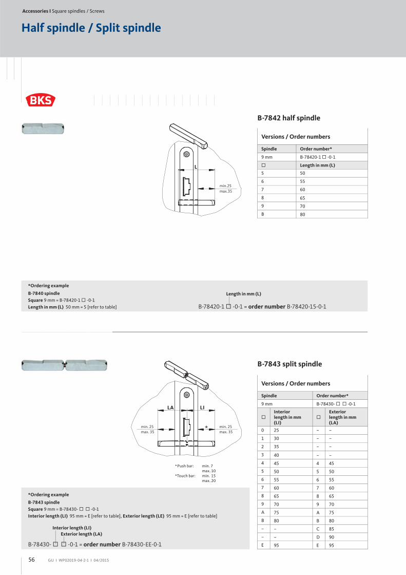
Half spindle / Split spindle
B-7842 half spindle
B-7843 split spindle
Versions / Order numbers
Spindle Order number*
9 mm B-78420-1 -0-1
Length in mm (L)
5 50
6 55
7 60
8 65
9 70
B 80
Versions / Order numbers
Spindle Order number*
9 mm B-78430- -0-1
Interior length in mm (LI)
Exterior length in mm (LA)
0 25 – –
1 30 – –
2 35 – –
3 40 – –
4 45 4 45
5 50 5 50
6 55 6 55
7 60 7 60
8 65 8 65
9 70 9 70
A 75 A 75
B 80 B 80
– – C 85
– – D 90
E 95 E 95
*Ordering example
B-7840 spindle
Square 9 mm = B-78420-1 -0-1
Length in mm (L) 50 mm = 5 [refer to table] B-78420-1 -0-1 = order number B-78420-15-0-1
Length in mm (L)
*Ordering example
B-7843 spindle
Square 9 mm = B-78430- -0-1
Interior length (LI) 95 mm = E [refer to table], Exterior length (LE) 95 mm = E [refer to table]
B-78430- -0-1 = order number B-78430-EE-0-1
Interior length (LI)
Exterior length (LA)
min.25max.35
L
min. 25max. 35
LI
min. 25max. 35
LA
*
* Push bar: min. 7
max. 10
*Touch bar: min. 15
max. 20
56
Accessories І Square spindles / Screws
GU І WP02019-04-2-1 І 04/2015
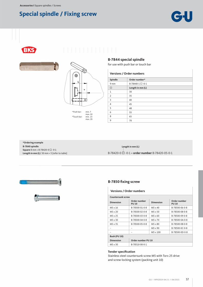
Special spindle / Fixing screw
Versions / Order numbers
Spindle Order number*
9 mm B-78440-1 -0-1
Length in mm (L)
1 30
2 35
3 40
4 45
5 48
6 55
8 65
9 70
*Ordering example
B-7840 spindle
Square 8 mm = B-78420-0 -0-1
Length in mm (L) 50 mm = 5 [refer to table] B-78420-0 -0-1 = order number B-78420-05-0-1
Length in mm (L)
B-7844 special spindle
for use with push bar or touch bar
Versions / Order numbers
Countersunk screw
DimensionOrder numberPU 10
DimensionOrder numberPU 10
M5 x 16 B-78500-01-0-8 M5 x 40 B-78500-06-0-8
M5 x 20 B-78500-02-0-8 M5 x 50 B-78500-08-0-8
M5 x 25 B-78500-03-0-8 M5 x 60 B-78500-09-0-8
M5 x 30 B-78500-04-0-8 M5 x 70 B-78500-0A-0-8
M5 x 35 B-78500-05-0-8 M5 x 80 B-78500-0B-0-8
– – M5 x 90 B-78500-0C-0-8
– – M5 x 100 B-78500-0D-0-8
Bush (PU 10)
Dimension Order number PU 10
M5 x 30 B-78510-00-0-1
Tender specifi cation
Stainless steel countersunk screw M5 with Torx 25 drive
and screw-locking system (packing unit 10)
B-7850 fi xing screw
L
*
* Push bar: min. 7
max. 10
*Touch bar: min. 15
max. 20
57
General information
GU І WP02019-04-2-1 І 04/2015
Product liability
According to the German Product Liability Act defi ning the liability of a manufacturer for his products, the following information about locks must be observed.
Non-observance exempts the manufacturer of his liability.
1. Product information and intended useA lock generally has the function to lock and block a door. Simple lock designs serve only to shut the door. This involves keeping the door shut in such a manner that it cannot be opened by pulling or pushing and instead be opened simply and easily by pressing a lever. The lock latch – generally called latch – serves as locking element.
Securing the closed door by blocking at least one deadbolt or latchbolt(= deadbolting latch) which engages in the appropriate recess in the frame or striker, is called blocking.
When extended, the deadbolt must be blocked against being pushed back. Moreover, door opening without the use of the appropriate key must be effi ciently hampered.
A door may be locked only when it is in fully closed position.
The length of the cylinder attachment screws must be selected to match the backset dimension of the lock or cropped to the appropriate length.
A mortise lock is a lock which is inserted into a mortise in the door leaf ('lock pocket') and fi xed with screws.
To ensure that a lock is used as intended, the following must be observed:– Locks, strikers, door hardware, attaching elements and cylinders selected must be compatible with each other.
– Installation, maintenance and possible replacement of the lock must be carried out in accordance with the state of the art. This is documented in standards related to these products and in the manufacturer's catalogues and instructions.
With locks for escape doors and special locks, the simultaneous operation of key and hardware (such as the lever handle) is not allowed as a rule.
Locks for escape doors and special locks may only be combined with locking cylinders with turn knob, if this is agreed with the lock manufac-turer by contract. It is generally assumed that only key owners have the right to operate the lock; in other words, the actuation of a lock through a knob cylinder (i.e. without key) is not considered a normal case.
The simultaneous retraction of latch and deadbolt simply by actuating the lever handle should be regarded as a special case and not generally as a replacement for retracting the deadbolt by turning the key.
Locking cylinders may only be installed in locks without reservation if they comply with a dimension standard (e.g. DIN 18252), and if the locks in turn are explicitly designed for cylinders to this standard.
In all other cases, manufacturers, dealers, fabricators or consumers of such locks have to ensure that the chosen locking cylinders are suitable for installation and for the intended use.
Mandatory legal regulations and manufacturer's instructions must be adhered to. For example, no locking cylinders with knob, turn or similar handle must be installed in panic locks.
General terms, if not explained in catalogues, brochures, price lists or on the internet, are defi ned in the standards relevant for these products (such as DIN 18250, DIN 18251, DIN 18252, DIN 18255, DIN 18257, DIN 18273, EN 179, EN 1125, EN 1303, EN 1906, EN 12209). Deviations from the particular relevant standard must be specifi ed in the order.
2. MisuseMisuse, meaning use other than the intended use of locks occurs if, e.g.,– the fl awless use is prevented by inserting foreign objects into the lock or into the latch striker.– the lock or the latch striker are manipulated in such a way that their construction or function is changed. – the deadbolt is extended to prevent the door from closing.– the function of the locking elements is blocked as a result of improper assembly or subsequent treatment, e.g., painting.– a load is applied on the lever handle exceeding the normal force applied by hand.
– unsuitable, e.g. dimensionally deviating or wrong keys are used. – the specifi ed clearance increases or decreases as a result of hinge readjustments or lowering of the door leaf. – a double door is opened by the passive leaf although not designed and approved for this feature.– objects or extremities are put between the door leaf and the jamb when the door closes.– activating the lever and the key simultaneously.
3. Product performanceTechnical requirements other than those determined in our catalogues, brochures or performance specifi cations must be agreed with us.
In this context, the relevant standards serve as guidelines (for example, DIN 18250, DIN 18251, DIN 18252, DIN 18255, DIN 18257, DIN 18273, EN 179, EN 1125, EN 1303, EN 1906, EN 12209).
These standards defi ne basic and additional requirements.
The serviceability of locks also depends on the operating frequency, operating method, environmental eff ects and maintenance.
Lock, latch striker, door hardware, locking cylinder and keys must be replaced as soon as problems occur despite proper maintenance.
This also applies after attempts to break locks and their accessories force-fully (burglary attempts).
4. Product maintenanceLocks must be lubricated with suitable lubricants at least once a year or more frequently depending on the use. Door hardware, latch striker and locking cylinder must be inspected for proper condition and attachment. Only cleaning agents not containing corrosive ingredients may be used.
5. Duty to inform and to instructIn order to comply with the informational and instructional duties prescri-bed by the German Product Liability Act, the following documents and services are made available to specialist dealers, locksmiths, architects, planners, fabricators and end users upon request:– catalogues, brochures– tender specifi cations, quotation documents, key combination records– the relevant standards, e.g., DIN 18250, DIN 18251, DIN 18252, DIN 18255, DIN 18257, DIN 18273, EN 179, EN 1125, EN 1303, EN 1906, EN 12209 (exclusive sale by Beuth Verlag GmbH, Berlin 30)– instructions for installation, operation and maintenance
For selecting, installing, operating and maintaining locks and hardware it is necessary that– architects and planners should request from us all required product information and follow it.– specialist dealers should observe the product information as well as the information given in the price lists, and specifi cally request all necessary instructions from us and forward these to the fabricators.– fabricators should observe all product information and specifi cally request operating and maintenance instructions from us and forward these to contractors and consumers.
58
GU І WP02019-04-2-1 І 04/2015
Standards and regulations
For doors and products related with doors, there is a whole range
of standards and directives. The most important (European)
standards are:
DIN 107
Building construction; identifi cation of right and left side
DIN 1080, part 1
Defi nitions, symbols and units in civil engineering, basics
DIN 4102, part 5 + 18
Part 5: Behaviour of building materials and components in fi re;
fi re barriers, barriers in lift wells and against fi re resistant
glazings
Part 18: Fire behaviour of building materials and components;
fi re barriers; verifi cation of automatic closure (continuous
performance test)
DIN 18 055
Windows; air permeability of joints, water tightness and mechani-
cal strain; requirements and testing
DIN 18 082, part 1 + 3
Part 1: Fire barriers, steel doors T30-1, type A
Part 3: Fire barriers, steel doors T30-1, type B
DIN 18 095, part 1 + 2
Part 1: Doors; smoke control doors; defninitions and
requirements
Part 2: Doors; smoke control doors; type testing of durability
and tightness
DIN 18 100
Doors; wall openings for doors; dimensions according to DIN
4172
DIN 18 101
Doors, doors for residential buildings; sizes of door leaves, positi-
on of hinges and lock; interdependence of dimensions
DIN 18 111, part 1
Door frames, steel door frames, standard door frames for rebated
doors in masonry
DIN 18 250
Mortise locks for fi re doors and smoke control doors
DIN 18 251
Locks; mortise locks for doors
DIN 18 252
Profi le cylinders for door locks; termniology, designations
DIN 18 255
Building hardware; door lever handles, backplates and escut-
cheons – defi nitions, dimensions, requirements and marking
DIN 18 257
Building hardware; security hardware – terms, dimensions, requi-
rements, tests and markings
DIN 18 273
Building hardware; lever handle units for fi re doors and smoke con-
trol doors – concepts and defi nitions, requirements and testing
DIN 18 357
German construction contract procedures (VOB), part C: General
technical specifi cations in construction contracts (ATV) –
mounting of door and window hardware
DIN 18 361
German construction contract procedures (VOB), part C: General
technical specifi cations in construction contracts (ATV) – glazing
work
DIN 68 706, part 1
Interior doors made from wood and wood-based panels,
door leaves – concepts, sizes, requirements
EN 179
Emergency exit devices operated by a lever handle or push pad
EN 1125
Panic exit devices operated by a horizontal bar
EN 1154
Building hardware – controlled door closing devices
EN 1303
Building hardware – cylinders for locks – requirements and test
methods
EN 1627
Windows, doors, shutters – Burglar inhibition – Requirements and
classifi cation
DIN EN 1628
Pedestrian doorsets, windows, curtain walling, grilles and shut-
ters – burglar resistance – test method for the determination of
resistance under static loading
DIN EN 1629
Pedestrian doorsets, windows, curtain walling, grilles and shut-
ters – burglar resistance – test method for the determination of
resistance under dynamic loading
EN 1630
Windows, doors, shutters. Burglar resistance. Test method for the
determination of resistance to manual burglary attempts
EN 1634, part 1 + 3
Fire resistance tests for doors and shutter assemblies
Part 1: Fire control doors and shutters
Part 3: Smoke control doors and shutters
EN 1906
Building hardware – lever handles and knob furniture –
requirements and test methods
59

General information
GU І WP02019-04-2-1 І 04/2015
Panic function B
Locked statusFunction from outside
Handle set to idle as the follower is decoupled. The door can only
be opened by key. When the key is turned, the follower is coupled
and the door can be opened with the lever handle. The follower
must subsequently be set to idle again by turning the key.
Function from inside
The door can be opened in the escape direction at any time.
Possible applicationsThe external lever handle makes the door suitable for use as a
connecting door.
Hallway doors in office buildings
Homes for the elderly
Secondary entrance doors
Secondary entrance doors in kindergartens, schools and
hotels
Outside Inside
Outside Inside
Outside Inside
Passage outwards
Passage outwards
Passage outwards
Passage inwards
No passage inwards
No passage inwards
Initial situationFunction from outside
Handle set to idle as the follower is decoupled. The door can only
be opened by key. When the key is turned, the follower is coupled
and the door can be opened with the lever handle. The follower
must subsequently be set to idle again by turning the key.
Function from inside
The door can be opened in the escape direction at any time.
Opening positionFunction from inside and outside
Passage possible in both directions via the lever handle; the latch
is retracted and the follower is coupled on both sides.
60

GU І WP02019-04-2-1 І 04/2015
Panic function E
Locked statusFunction from outside
Door opening only by key: the latch is retracted.
Function from inside
The door can be opened in escape direction at any time.
Possible applicationsAs the fi xed knob or push/pull handle is on the outside, access
from outside is only possible using the key.
Doors on transformer stations and boiler rooms
Lift shafts
Underground car parks
Entrance to stores and business houses
Entrance to tenements and multi-family houses
Outside Inside
Outside Inside
Initial situationFunction from outside
Only a fi xed knob or push/pull handle can be used as hardware.
Door opening only by key: the latch is retracted.
Function from inside
The door can be opened in the escape direction at any time.
Passage outwards
No passage inwards
Passage outwards
No passage inwards
Passage inwards
61
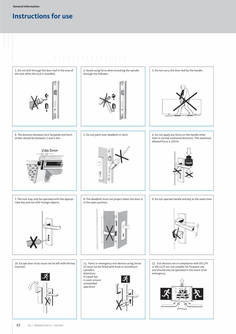
General information
GU І WP02019-04-2-1 І 04/2015
11. Panic or emergency exit devices using Series
23 must not be fi tted with knob or thumbturn
cylinders.
Attention:
if a push bar
is used, ensure
unimpeded
operation
Instructions for use
1. Do not drill through the door leaf in the area of
the lock when the lock is installed.
4. The distance between lock faceplate and latch
striker should be between 2 and 5 mm.
2. Avoid using force when knocking the spindle
through the follower.
5. Do not paint over deadbolt or latch.
3. Do not carry the door leaf by the handle.
6. Do not apply any force on the handle other
than in normal rotational direction. The maximum
allowed force is 150 N.
9. Do not operate handle and key at the same time.
12. Exit devices not in compliance with EN 179
or EN 1125 are not suitable for frequent use
and should only be operated in the event of an
emergency.
7. The lock may only be operated with the approp-
riate key and not with foreign objects.
8. The deadbolt must not project when the door is
in the open position.
10. Escape door locks must not be left with the key
inserted.
62
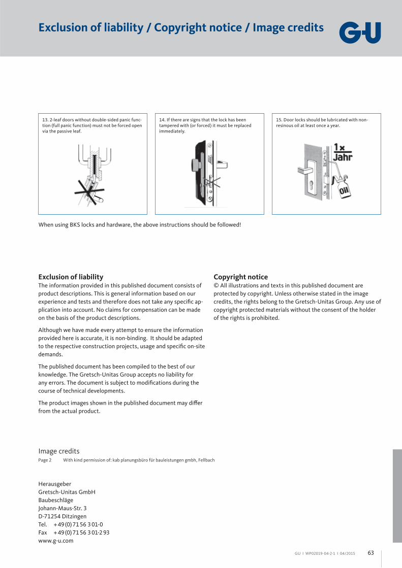
GU І WP02019-04-2-1 І 04/2015
13. 2-leaf doors without double-sided panic func-
tion (full panic function) must not be forced open
via the passive leaf.
14. If there are signs that the lock has been
tampered with (or forced) it must be replaced
immediately.
15. Door locks should be lubricated with non-
resinous oil at least once a year.
When using BKS locks and hardware, the above instructions should be followed!
Exclusion of liability / Copyright notice / Image credits
Exclusion of liabilityThe information provided in this published document consists of
product descriptions. This is general information based on our
experience and tests and therefore does not take any specifi c ap-
plication into account. No claims for compensation can be made
on the basis of the product descriptions.
Although we have made every attempt to ensure the information
provided here is accurate, it is non-binding. It should be adapted
to the respective construction projects, usage and specifi c on-site
demands.
The published document has been compiled to the best of our
knowledge. The Gretsch-Unitas Group accepts no liability for
any errors. The document is subject to modifi cations during the
course of technical developments.
The product images shown in the published document may diff er
from the actual product.
Copyright notice© All illustrations and texts in this published document are
protected by copyright. Unless otherwise stated in the image
credits, the rights belong to the Gretsch-Unitas Group. Any use of
copyright protected materials without the consent of the holder
of the rights is prohibited.
Image creditsPage 2 With kind permission of: kab planungsbüro für bauleistungen gmbh, Fellbach
Herausgeber
Gretsch-Unitas GmbH
Baubeschläge
Johann-Maus-Str. 3
D-71254 Ditzingen
Tel. + 49 (0) 71 56 3 01-0
Fax + 49 (0) 71 56 3 01-2 93
www.g-u.com
63
BKS GmbH
Heidestr. 71
D-42549 Velbert
Tel. + 49 (0) 20 51 2 01-0
Fax + 49 (0) 20 51 2 01-97 33
Gretsch-Unitas GmbH
Baubeschläge
Johann-Maus-Str. 3
D-71254 Ditzingen
Tel. + 49 (0) 71 56 3 01-0
Fax + 49 (0) 71 56 3 01-77 980
WP
02
01
9-0
4-2
-1
04
/20
15
P
rin
ted
in G
erm
any
www.g-u.com