Dominion Energy - cigre-usnc.org · Individual simulations of the real SVC and STATCOM controllers...
27
Dominion Energy ® Rebecca Rye 1 November 2017 1 Real-Time Testing of STATCOM and SVC Controllers
Transcript of Dominion Energy - cigre-usnc.org · Individual simulations of the real SVC and STATCOM controllers...
Dominion Energy®
Rebecca Rye
1 November 20171
Real-Time Testing of STATCOM and
SVC Controllers

Acknowledgements
1 November 20172
Kyle ThomasDr. Hung-Ming Chou
Murat SezerArnold Rischer
Hezi TouafAdam Sparacino
Chathura Patabandi

Power Electronic Devices in Power Systems
1 November 20173
Solar farm
SVC & STATCOM (for voltage regulation)
Wind farm
High Voltage Direct Current
(HVDC)

Types of Shunt Devices for Voltage Regulation
1 November 20174
Fixed Cap/Fixed Reactor
SVC STATCOM
Switch mechanism Mechanical Power Electronics Power Electronics
Reactive power (Q) control method Manual / Automatic Automatic Automatic
Q change step size Large Small Small
Both capacitive & inductive? No Yes Yes
Need harmonic filter? No Large filter Small filter
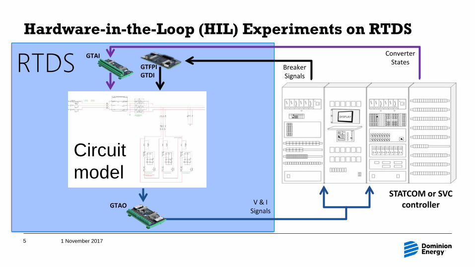
V & I Signals
GTAO
RTDSHardware-in-the-Loop (HIL) Experiments on RTDS
1 November 20175
STATCOM or SVC controller
GTFPIGTDI
Breaker Signals
GTAI Converter States
Circuit model

Introduction to the STATCOM
1 November 20176
Static Synchronous CompensatorA regulating device that can act as either a source or sink of reactive power using IGBTs
DC/AC Multilevel converter
2-level converter 3-level converter

Introduction to the STATCOM
1 November 20177
Static Synchronous CompensatorA regulating device that can act as either a source or sink of reactive power
Reactive power control
Current control
Switch control
Current reference
Dutyratio
Reactive power control(1) Fixed Q mode / Manual mode (2) Voltage Control Mode
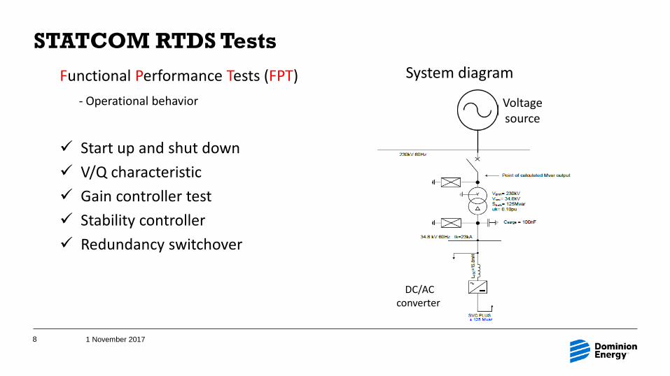
STATCOM RTDS Tests
1 November 20178
Functional Performance Tests (FPT)- Operational behavior
Start up and shut down V/Q characteristic Gain controller test Stability controller Redundancy switchover
System diagram
DC/AC converter
Voltage source

STATCOM RTDS Tests
1 November 20179
Mode transfer from fixed Q (FQM) to voltage control (VCM)
(1) In fixed Q (FQM) Q reference = 0
(2) Mode transfer
(4) Operation point in voltage control (VCM)
𝑉𝑉
𝑄𝑄CapacitiveInductive
Q >0
(3) Gain of VCM controller is adjusted
Q
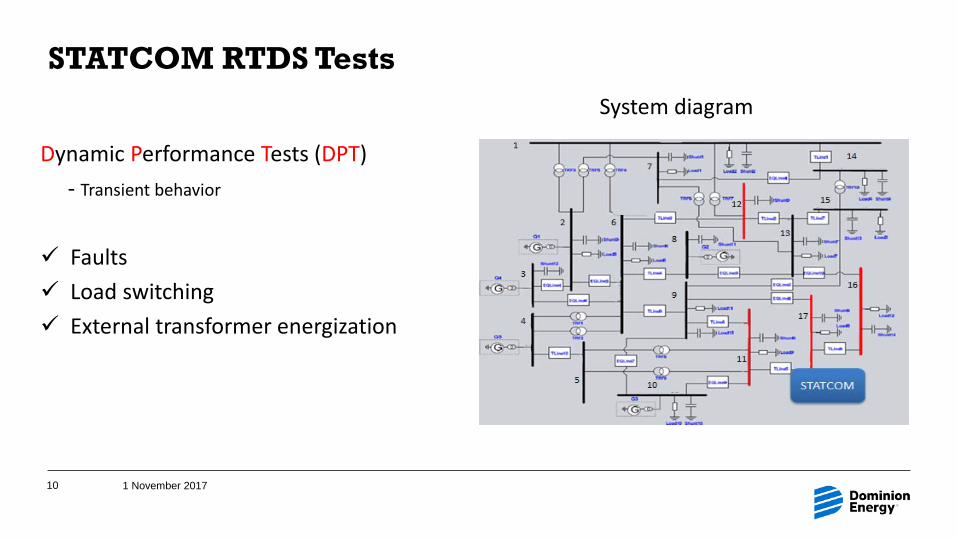
STATCOM RTDS Tests
1 November 201710
System diagram
Dynamic Performance Tests (DPT)- Transient behavior
Faults Load switching External transformer energization

STATCOM RTDS Tests
1 November 201711
Dynamic performance of STATCOM in phase to phase fault
t1
t1 : Line to line fault
t2
t2 : STATCOM blockedbecause of undervoltage
t3
t3 : Fault is clearSTATCOM is unblocked
Digital Signals

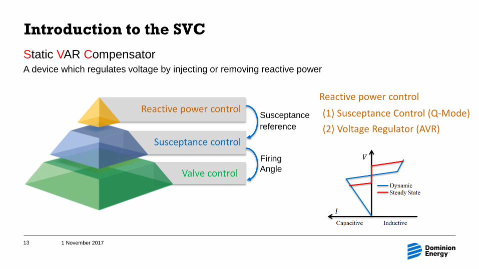
Introduction to the SVC
1 November 201712
Static VAR CompensatorA device which regulates voltage by injecting or removing reactive power using:
• TCR: Thyristor Controlled Reactor• TSC: Thyristor Switched Capacitor
IV①
②
V
I ① fires
② fires
GATE
GATE
Light Triggered Thyristor:
Introduction to the SVC
1 November 201713
Reactive power control
Susceptance control
Valve control
Susceptancereference
Firing Angle
Reactive power control(1) Susceptance Control (Q-Mode) (2) Voltage Regulator (AVR)
Static VAR CompensatorA device which regulates voltage by injecting or removing reactive power

SVC RTDS Tests
1 November 201714
System Verification Tests- Operation and static/dynamic characteristics
Start up & shut down Protection V-I characteristics Faults
System diagramVoltage source w/ impedance
TCR-200 to 0 Mvar
TSC+200 or 0 Mvar
5th & 7th
Harmonic Filter+50 Mvar
Spare 5th & 7th
Harmonic Filter+50 Mvar
3rd
Harmonic Filter+72 Mvar
250 MVA500 kV : 25 kV
500 kV
25 kV bus

SVC – VC Mode
1 November 201715
Vsys1
B
InductiveCapacitiveI (pu)
V (pu)
VrefA
Linear Control Range
SVC DynamicCharacteristic
USED WITH EXPRESS AND SPECIFIC PERMISSION FROM MITSUBISHI ELECTRIC CORPORATION

SVC RTDS Tests
1 November 201716
Performance of SVC in phase to ground fault under voltage-control mode
0.80.85
0.90.95
11.05
V (p
u)
V
-2
-1
0
1
2
Cur
rent
(kA
) Transformer Current ATransformer Current BTransformer Current C
-100
0
100
200
300
Q (M
var)
SVC_Q
-40
-20
0
20
40
0 0.05 0.1 0.15 0.2 0.25 0.3 0.35 0.4 0.45 0.5
Cur
rent
(kA
)
t (s)
Fault Current
t1
t1 : L-G fault applied
t2
t2 : SVC injects Q to increase V
t3
t3 : Fault is clear; SVC’s Q brifelyincreases to regulate voltage to 1 pu
t4 : SVC injects less Q as voltage is boosted to reference value
t4
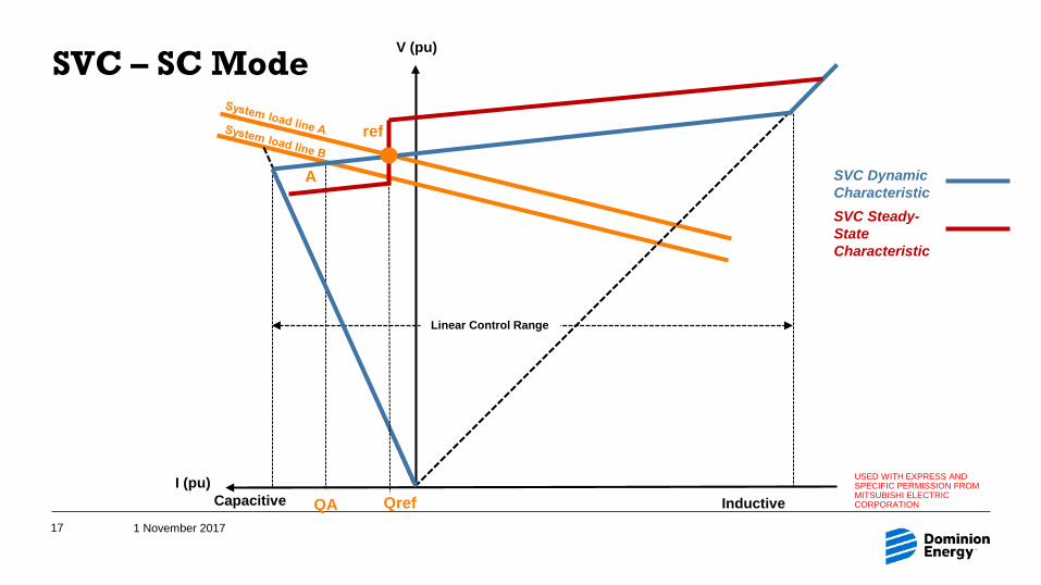
SVC – SC Mode
1 November 201717
QA
A
InductiveCapacitiveI (pu)
V (pu)
ref
Qref
Linear Control Range
SVC DynamicCharacteristic SVC Steady-State Characteristic
USED WITH EXPRESS AND SPECIFIC PERMISSION FROM MITSUBISHI ELECTRIC CORPORATION
020406080
100120140
0 20 40 60 80 100 120
Q (M
var)
t (s)
SVC_Q
SVC RTDS Tests
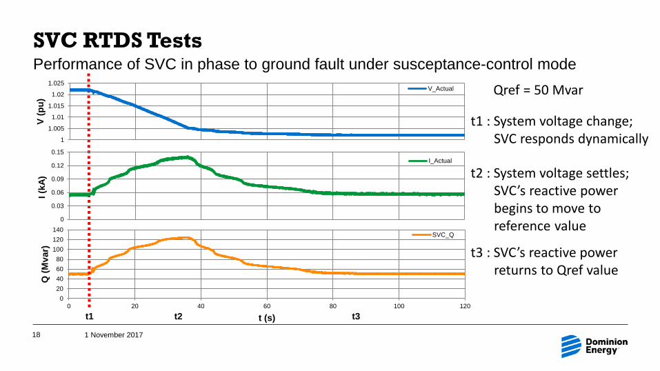
1 November 201718
t1
t1 : System voltage change; SVC responds dynamically
t2
t2 : System voltage settles; SVC’s reactive powerbegins to move toreference value
1
1.005
1.01
1.015
1.02
1.025
V (p
u)
V_Actual
0
0.03
0.06
0.09
0.12
0.15
I (kA
)
I_Actual
t3
t3 : SVC’s reactive power returns to Qref value
Qref = 50 Mvar
Performance of SVC in phase to ground fault under susceptance-control mode

RTDS Tests – Conclusions
1 November 201719
1) Real STATCOM & SVC controllers can be tested using hardware-in-the-loop technologyon RTDS racks.
2) Verified the functionality and operation of Dominion Energy’s new controllers per the manufacturers’ specifications.
3) Understand the controllers and able to predict the response of the controllers in various scenarios.
4) Further tested the functionality of the controllers by performing more protection sequences and various kinds of faults in the simple model.

Interaction of the STATCOM and SVC
1 November 201720
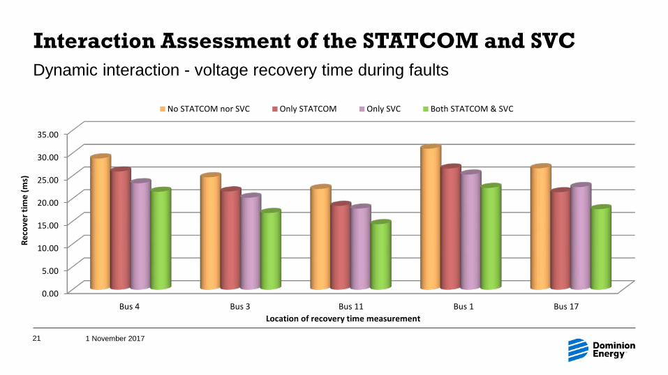
Interaction Assessment of the STATCOM and SVC
1 November 201721
Dynamic interaction - voltage recovery time during faults
0.00
5.00
10.00
15.00
20.00
25.00
30.00
35.00
Reco
ver t
ime
(ms)
Location of recovery time measurement
No STATCOM nor SVC Only STATCOM Only SVC Both STATCOM & SVC
Bus 4 Bus 3 Bus 11 Bus 1 Bus 17
Progress
1 November 201722
Individual simulations of the real SVC and STATCOM controllers are completed using the RTDS simulation equipment and hardware-in-the-loop functionality.
Operational and dynamic performances of the STATCOM and the SVC are tested and meet the criteria from vendor reports.
Using an equivalent system model of an urban area, the STATCOM and the SVC controllers are successfully included in the same simulation. No negative interactions are found between the SVC and STATCOM when in close proximity.
All tests procedures & results obtained are documented; documentation can be used for training purposes
Future work(1) Build virtual STATCOM or SVC models in RTDS that emulate the real controller.(2) Use the virtual models to study the interactions of multiple devices in the same network.
Thank you!
1 November 201723

Appendicies
1 November 201724
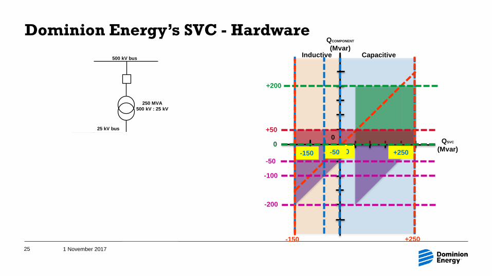
Dominion Energy’s SVC - Hardware
1 November 201725
TCR-200 to 0 Mvar
TSC+200 or 0 Mvar
5th & 7th HF+50 Mvar
3rd HF+72 Mvar
250 MVA500 kV : 25 kV
500 kV bus
25 kV bus
Inductive Capacitive
QCOMPONENT
(Mvar)
QSVC
(Mvar)
0+50
+250
-200
-100
-150 00
-50
+200
-50
-150 +250
0

Using Reactive Power for Voltage Regulation
1 November 201726
InductorCapacitorResistor
𝑉𝑉𝐼𝐼
𝑉𝑉𝐼𝐼
𝐼𝐼𝑉𝑉

Reactive Power for Voltage Regulation
November 1, 201727
Original
𝑉𝑉𝑔𝑔 𝑉𝑉𝐿𝐿
𝐼𝐼𝐿𝐿
𝑉𝑉𝑔𝑔
𝐼𝐼𝐿𝐿
∆𝑉𝑉
Capacitive compensation𝐼𝐼𝐿𝐿
∆𝑉𝑉
Inductive compensation𝐼𝐼𝐿𝐿
∆𝑉𝑉
𝑉𝑉𝐿𝐿∆𝑉𝑉
𝐼𝐼𝐿𝐿
𝑉𝑉𝑔𝑔
∆𝑉𝑉
𝑉𝑉𝑔𝑔
𝐼𝐼𝐿𝐿
𝑉𝑉𝐿𝐿 ∆𝑉𝑉𝑉𝑉𝐿𝐿