DOiT Workbook Answer Key - Lagout Security...The material in this lab workbook remains the...
59
Revision 7.0 (10/20/2005) DOiT-200v6-SCENARIO 1 Page 1 © 2005 Copyright NetMasterClass, LLC - All rights reserved. 1-888-677-2669 http://www.netmasterclass.net 13530 Dulles Technology Drive, Suite #150, Herndon, VA 20171 The material in this lab workbook remains the intellectual property of NetMasterClass., LLC The purchaser cannot re-distribute the materials in any format or resell this workbook NETMASTERCLASS ROUTING AND SWITCHING CCIE® TRACK DOiT-200v6 VOLUME II N1 R3 R4 N2 3 3 1 1 R2 3 3 R5 3 3 2 2 4 4 4 4 4 1 I2 R5 R6 R2 R3 R1 N1 R7 I3 I4 I5 Scenario 1 ANSWER KEY FOR CCIE® CANDIDATES
Transcript of DOiT Workbook Answer Key - Lagout Security...The material in this lab workbook remains the...

Revision 7.0 (10/20/2005) DOiT-200v6-SCENARIO 1 Page 1
© 2005 Copyright NetMasterClass, LLC - All rights reserved.
1-888-677-2669 http://www.netmasterclass.net 13530 Dulles Technology Drive, Suite #150, Herndon, VA 20171
The material in this lab workbook remains the intellectual property of NetMasterClass., LLC The purchaser cannot re-distribute the materials in any format or resell this workbook
NETMASTERCLASS
ROUTING AND SWITCHING CCIE® TRACK
DOiT-200v6 VOLUME II
N1
R3 R4 N233
1
1
R2 33 R5 3
3
2 244
4
4
4
1
I2
R5 R6R2
R3
R1
N1 R7I3
I4
I5
Scenario 1
ANSWER KEY
FOR
CCIE® CANDIDATES

Revision: 7.0 (10/20/2005) DOiT-200v6- SCENARIO 1 Page 2
© 2005 Copyright NetMasterClass, LLC - All rights reserved.
1-888-677-2669 http://www.netmasterclass.net 13530 Dulles Technology Drive, Suite #150, Herndon, VA 20171
The material in this lab workbook remains the intellectual property of NetMasterClass., LLC The purchaser cannot re-distribute the materials in any format or resell this workbook
Disclaimer
NetMasterClass, LLC is an independent training and consulting company based in Herndon, Virginia. The terms “Cisco”, “Cisco Systems” and “CCIE” are the trademarks of Cisco Systems, Inc. NetMasterClass, LLC is Cisco Learning Partner.
Cisco Non-Disclosure Agreement Compliance All products and services offered by NetMasterClass, LLC are in full compliance with the Cisco CCIE Lab non-disclosure agreement. The content of the NetMasterClass CCIE preparation materials is based upon the NetMasterClass “issue spotting and analysis” internetwork training methods. NOTE: To use this document to its maximum effectiveness, access the SHOWiT engine while reviewing each section of this Answer Key.

Revision: 7.0 (10/20/2005) DOiT-200v6- SCENARIO 1 Page 3
© 2005 Copyright NetMasterClass, LLC - All rights reserved.
1-888-677-2669 http://www.netmasterclass.net 13530 Dulles Technology Drive, Suite #150, Herndon, VA 20171
The material in this lab workbook remains the intellectual property of NetMasterClass., LLC The purchaser cannot re-distribute the materials in any format or resell this workbook
DOiT-200v6 Scenario 1: Spot the Issue Answer Key
Table of Contents 1.1 Frame Relay ......................................................................................................................................6 1.2 Catalyst Configuration .......................................................................................................................7 1.3 OSPF...............................................................................................................................................17 1.4 RIP...................................................................................................................................................22 1.5 EIGRP..............................................................................................................................................25 1.6 BGP .................................................................................................................................................26 1.7 IPv6..................................................................................................................................................30 1.8 Traffic Management.........................................................................................................................41 1.9 Address Administration....................................................................................................................43 1.10 Security............................................................................................................................................45 1.11 IOS Features ...................................................................................................................................47 1.12 QOS.................................................................................................................................................47 1.13 Catalyst Specialties .........................................................................................................................50 1.14 Gateway Redundancy .....................................................................................................................51 1.15 Multicast...........................................................................................................................................53 1.16 NTP..................................................................................................................................................57
REGARDLESS OF ANY CONFIGURATION YOU PERFORM IN THIS EXAM, IT IS VERY IMPORTANT TO CONFORM TO THE GENERAL GUIDELINES PROVIDED BELOW. IF YOU DO NOT CONFORM TO THEM, THIS CAN RESULT IN A SIGNIFICANT DEDUCTION OF POINTS IN YOUR FINAL EXAM SCORE.

Revision: 7.0 (10/20/2005) DOiT-200v6- SCENARIO 1 Page 4
© 2005 Copyright NetMasterClass, LLC - All rights reserved.
1-888-677-2669 http://www.netmasterclass.net 13530 Dulles Technology Drive, Suite #150, Herndon, VA 20171
The material in this lab workbook remains the intellectual property of NetMasterClass., LLC The purchaser cannot re-distribute the materials in any format or resell this workbook
Goals and Restrictions • IPv4 subnets displayed in the Scenario diagram belong to network 172.16.0.0/16. • IPv6 networks used in the Scenario will use a FEC0::/125 network unless specified otherwise. • Do not use any static routes. • Advertise Loopback interfaces with their original masks. • Network 0.0.0.0/0 should not appear in any routing table (show ip route). • Do not use the “ip default-network” command. • Do not introduce any new IP addresses between R2 and CAT2. • All IP addresses involved in this scenario must be reachable. • Use conventional routing algorithms.
Explanation of Each of the Goals and Restrictions: IPv4 subnets displayed in the Scenario diagram belong to network 172.16.0.0/16. All IP addresses in this Exam belong to the 172.16.0.0/16 address space with the exception of a set of prefixes used in the BGP section. Do not use any static routes. Static routes can be used to solve a range of reachability problems. However, you cannot use them. You must rely on skillful configuration of all your unicast routing protocols. Do not use 0.0.0.0 anywhere in this scenario. A 0.0.0.0/0 entry can also be used to solve a range of reachability problems. In particular, a 0.0.0.0/0 entry can be used to set up the gateway of last resort. In this exercise, you cannot use any 0.0.0.0/0 entries. A suggested alternative to using the 0.0.0.0/0 route to solve the reachability problem is route summarization. A detailed explanation of using summarization to solve the reachability problem is provided in Section 1.5, the RIP Section. Do not use the “ip default-network” command. This can also be used to solve the reachability issues by setting the gateway of last resort. This command generates 0.0.0.0/0 in the RIP environment. You cannot use it in this Scenario. All IP addresses involved in this scenario must be reachable. This is a key goal to observe. This requires that all of your IGP’s are configured properly. Also, all of your routing policy tasks must be configured properly. The key elements of your routing policy include route redistribution and the controlling of routing updates using distribute-lists, route-maps and the distance
Revision: 7.0 (10/20/2005) DOiT-200v6- SCENARIO 1 Page 5
© 2005 Copyright NetMasterClass, LLC - All rights reserved.
1-888-677-2669 http://www.netmasterclass.net 13530 Dulles Technology Drive, Suite #150, Herndon, VA 20171
The material in this lab workbook remains the intellectual property of NetMasterClass., LLC The purchaser cannot re-distribute the materials in any format or resell this workbook
command. A key point to remember about this exam is: the term “redistribution” is never explicitly used in this exam. However, you must perform redistribution in order to assure that all ip addresses are reachable without the use of static routes or 0.0.0.0/0 routes.
Use conventional routing algorithms. This restriction prevents you from solving any problems by configuring policy routing. At the heart of this restriction is the interpretation of the “conventional routing algorithms”. Although this phrase can be interpreted in a number of different ways, the interpretation applied in this workbook is:
CONVENTIONAL ROUTING ALGORITHMS ARE ROUTING ALGORITHMS THAT APPLY DESTINATION BASED PREFIX LOOKUPS IN A ROUTING TABLE. CONVENTIONAL ROUTING ALGORITHMS DO NOT USE ANY OTHER TYPE OF INFORMAITON OTHER THAN THE DESTINATION ADDRESS TO MAKE A PACKET FORWARDING DECISION.
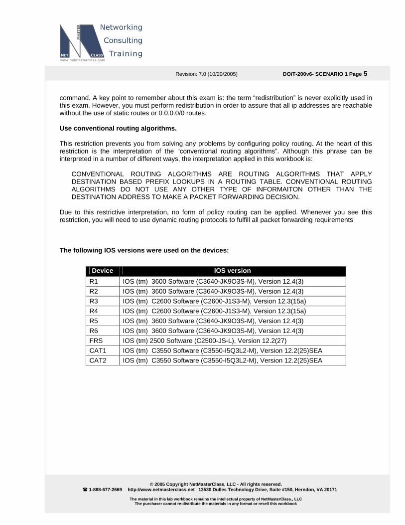
Due to this restrictive interpretation, no form of policy routing can be applied. Whenever you see this restriction, you will need to use dynamic routing protocols to fulfill all packet forwarding requirements The following IOS versions were used on the devices:
Device IOS version R IO1 S (tm) 3600 Software (C3640-JK9O3S-M), Version 12.4(3) R IO2 S (tm) 3600 Software (C3640-JK9O3S-M), Version 12.4(3) R3 IOS (tm) C2600 Software (C2600-J1S3-M), Version 12.3(15a) R4 IOS (tm) C2600 Software (C2600-J1S3-M), Version 12.3(15a) R IO5 S (tm) 3600 Software (C3640-JK9O3S-M), Version 12.4(3) R IO6 S (tm) 3600 Software (C3640-JK9O3S-M), Version 12.4(3) F IORS S (tm) 2500 Software (C2500-JS-L), Version 12.2(27) C IO 25)SEA AT1 S (tm) C3550 Software (C3550-I5Q3L2-M), Version 12.2(CAT2 IOS (tm) C3550 Software (C3550-I5Q3L2-M), Version 12.2(25)SEA

Revision: 7.0 (10/20/2005) DOiT-200v6- SCENARIO 1 Page 6
© 2005 Copyright NetMasterClass, LLC - All rights reserved.
1-888-677-2669 http://www.netmasterclass.net 13530 Dulles Technology Drive, Suite #150, Herndon, VA 20171
The material in this lab workbook remains the intellectual property of NetMasterClass., LLC The purchaser cannot re-distribute the materials in any format or resell this workbook
1.1 Frame Relay
HIDDEN ISSUES TO SPOT WITH THE FRAME-RELAY CONFIGURATION Issue: You are instructed to use “PVC’s displayed in the diagram only”. No dynamic entries are allowed in the Frame Relay map tables. Solution: 1. When examining the Scenario 1 diagram, you see that the Layer 3 connections over the NBMA
network reflect a hub and spoke topology with router R1 as the hub.
2. Disable inverse arp so that no undesirable dynamic inverse-arp entries are found on any of the routers. Unneeded inverse-arp entries could violate the constraint specified in the task.
3. Provide static frame-relay mappings on each of the Frame-Relay attached routers. Make sure that routers R2 and R3 possess a Frame-Relay map statement to router R1 and that each of the spoke routers also possesses map statements to one another.
Verification: 1. Issue the show frame-relay pvc command on each router and verify the number of DLCIs marked as
Local, Switched and Unused. a. Routers R2, R3 and R4 should indicate 3 Active with 1 Local and 2 Unused. b. R1 should indicate 3 Active and Local. c. If you are seeing 3 Active and Local on the spokes and you have turned off inverse-arp, then
try saving your configuration and reloading. If you see any DLCI’s listed as Deleted, check you have not mistyped a DLCI in a map or interface-dlci command.
2. Issue the command show frame-relay map. Below is the result for R2. Note there are maps to its
own ip address (so it can ping itself), to the hub, R1, and to the other spoke in the subnet. Also note the broadcast keyword on each map.
R2#sh frame map Serial0/0 (up): ip 172.16.123.1 dlci 201(0xC9,0x3090), static, broadcast, CISCO, status defined, active Serial0/0 (up): ip 172.16.123.2 dlci 201(0xC9,0x3090), static, broadcast, CISCO, status defined, active Serial0/0 (up): ip 172.16.123.3 dlci 201(0xC9,0x3090), static, broadcast, CISCO, status defined, active
Beware of any maps to 0.0.0.0! They indicate an inverse-arp mapping to an interface without a layer 3 address! To get rid of these, save your configuration and reload.

Revision: 7.0 (10/20/2005) DOiT-200v6- SCENARIO 1 Page 7
© 2005 Copyright NetMasterClass, LLC - All rights reserved.
1-888-677-2669 http://www.netmasterclass.net 13530 Dulles Technology Drive, Suite #150, Herndon, VA 20171
The material in this lab workbook remains the intellectual property of NetMasterClass., LLC The purchaser cannot re-distribute the materials in any format or resell this workbook
D IP InR 17 Physical R 17 Lo oint S0/0.N R 17 PhR 17 Physical R 17 Physical
Issue: “use physical interfaces wherever possible, otherwise use point-to-point logical interfaces.” Solution: This requirement is straightforward on routers R2, R3 and R4: all of them were configured with physical interfaces. The challenge was determining how to configure R1. R1 used its physical Serial interface to terminate DLCI’s 102 and 103 on the 172.16.123.0/24 subnet and a point-to-point subinterface to terminate the DLCI 104 for the 172.16.14.0/24 subnet. See the following table:
evice address on Frame Relay terface type 1 1
2.16.123.1 2.16.14.1
S0/0 gical point-to-p
2 2.16.123.2 ysical S0/0 3 4
2.16.123.3 2.16.123.1
S0/0 S0/0
To obtain a tion, access the comprehensive view of the configuration tasks in this secSHOWiT engine. With the SHOWiT engine, you can enter in over 1000 IOS commands as well a collection of NMC proprietary commands such as “show all”.
.2 Ca a1
t lyst Configuration
HIDDEN ISSUES TO SPOT WITH THE CATALYST 3550 SWITCH CONFIGURATION Gener
al Tasks:
ike any Catalyst 3550 configuration, you must address the following basic configuration requirements: ode, configuring trunk ports, statically assigning ports to VLAN’s. For a good reference
st 3550 configuration tasks, download the following Tech-Note from the Technical
Lsetting the VTP m
n basic CatalyoLibrary on the NetMasterClass web-site: “Performing Basic Configuration Tasks on the Catalyst 3550”.

Revision: 7.0 (10/20/2005) DOiT-200v6- SCENARIO 1 Page 8
© 2005 Copyright NetMasterClass, LLC - All rights reserved.
1-888-677-2669 http://www.netmasterclass.net 13530 Dulles Technology Drive, Suite #150, Herndon, VA 20171
The material in this lab workbook remains the intellectual property of NetMasterClass., LLC The purchaser cannot re-distribute the materials in any format or resell this workbook
VLAN Distribution Diagram
R6
VLAN40
VLAN10
CAT1 CAT2
R2 R3 R1
Fa0/0
Fa0/2
Fa0/1 Fa0/0
Fa0/4 Fa0/3
Fa0/13Fa0/13
Fa0/14Fa0/14
Fa0/1
R5 R4 FRS
Fa0/0
Fa0/6
Fa0/0
Fa0/8
Fa0/1
Fa0/9 Fa0/5
Fa0/0 E0
Fa0/7
Fa0/0
VLAN20VLAN30
VLAN3000
ISL Trunk
DOT1Q Trunk
DOT1Q Trunk
Issue: Create required VLANs and assign access ports. Configure the VTP mode suitable for all other tasks in this exam Solution: 1. Set required VTP Mode: Task hints that we should look around at the entire exam to figure out which
VTP mode to use. You will notice there is a VLAN 3000 required. The default VTP version 2 does not support extended range VLANs (VLANs numbered above 1023). So we need to set the VTP mode to transparent. The output below resulted from trying to create VLAN 3000 while in the default VTP mode, Server:
CAT1(config)#vtp mode server Setting device to VTP SERVER mode CAT1(config)#vlan 3000 CAT1(config-vlan)#end % Failed to create VLANs 3000 VLAN(s) not available in Port Manager. Failed to commit extended VLAN(s) changes.
Revision: 7.0 (10/20/2005) DOiT-200v6- SCENARIO 1 Page 9
© 2005 Copyright NetMasterClass, LLC - All rights reserved.
1-888-677-2669 http://www.netmasterclass.net 13530 Dulles Technology Drive, Suite #150, Herndon, VA 20171
The material in this lab workbook remains the intellectual property of NetMasterClass., LLC The purchaser cannot re-distribute the materials in any format or resell this workbook
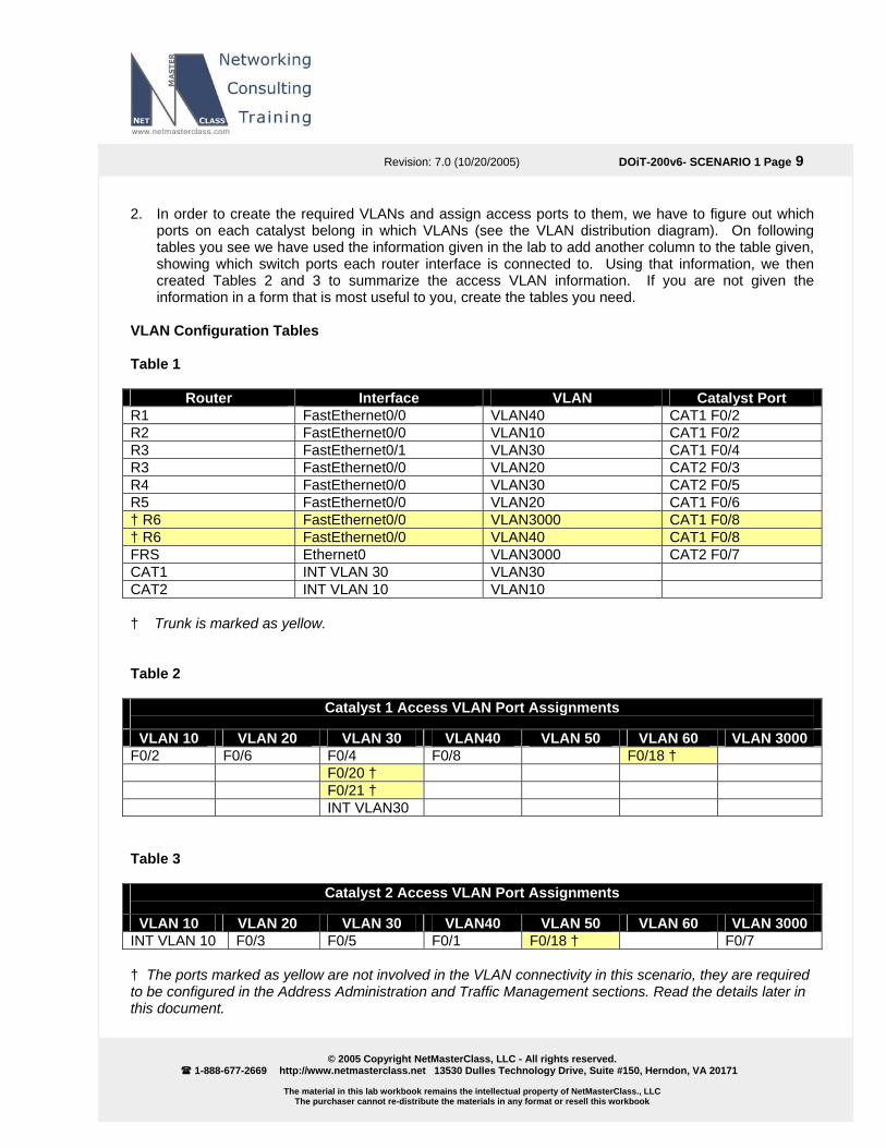
2. In order to create the required VLANs and assign access ports to them, we have to figure out which ports on each catalyst belong in which VLANs (see the VLAN distribution diagram). On following tables you see we have used the information given in the lab to add another column to the table given, showing which switch ports each router interface is connected to. Using that information, we then created Tables 2 and 3 to summarize the access VLAN information. If you are not given the information in a form that is most useful to you, create the tables you need.
VLAN Configuration Tables Table 1
Router Interface VLAN Catalyst Port
R Fa VLAN40 CAT1 1 stEthernet0/0 F0/2 R Fa VL CAT1 2 stEthernet0/0 AN10 F0/2 R Fa VL CAT1 3 stEthernet0/1 AN30 F0/4 R Fa VL CAT2 3 stEthernet0/0 AN20 F0/3 R Fa VL CAT2 4 stEthernet0/0 AN30 F0/5 R Fa VL CAT1 5 stEthernet0/0 AN20 F0/6 † R6 FastEthernet0/0 VLAN3000 CAT1 F0/8 † R6 FastEthernet0/0 VLAN40 CAT1 F0/8 FR Et VL CAT2 S hernet0 AN3000 F0/7 C IN VL AT1 T VLAN 30 AN30 C IN VL AT2 T VLAN 10 AN10 † k is marked as yellow Table 2
Trun .
Catalyst 1 Access VLAN Port Assignments
VLAN 10 VLAN 20 VLAN 30 VLAN40 VLAN 50 VLAN 60 VLAN 3000 F0/2 F0/6 F0/4 F0/8 F0/18 † F0/20 † F0/21 † I NT VLAN30 Ta
ble 3
Ca 2 Access Port As ments talyst VLAN sign
VLAN 10 VLAN 20 VLAN 30 VLAN40 VLAN 50 VLAN 60 VLAN 3000 INT VLAN 10 F0/3 F0/5 F0/1 F0/18 † F0/7 † he ports marked as yellow are not involved in the VLAN conn y in this scenario, they are required to be configured in the Addres ration an ffic Management sections later in this document.
T ectivits Administ d Tra . Read the details

Revision: 7.0 (10/20/2005) DOiT-200v6- SCENARIO 1 Page 10
© 2005 Copyright NetMasterClass, LLC - All rights reserved.
1-888-677-2669 http://www.netmasterclass.net 13530 Dulles Technology Drive, Suite #150, Herndon, VA 20171
The material in this lab workbook remains the intellectual property of NetMasterClass., LLC The purchaser cannot re-distribute the materials in any format or resell this workbook
of VLAN10 configuration on the CAT1:
Example
CAT1#sh run vlan 10 Building configuration...
con n: Current !
figuratio
vlan 10 name NET-1end
0
CAT1#
oes not require to configure only the necessary VLANs per switch:
Verification:
Status Ports ----------- --------- -------------------------------
Fa0/9, Fa0/10, Fa0/15, Fa0/16
Fa0/24, Gi0/1, Gi0/2
All other VLANs are configured similarly according to VLAN name table and consistently on both switches,since scenario d
CAT1#sh vlan brief VLAN Name ---- ---------------------1 default active Fa0/1, Fa0/3, Fa0/5, Fa0/7 Fa0/17, Fa0/19, Fa0/22, Fa0/23 10 NET-10 active Fa0/2 20 NET-20 active Fa0/6 30 NET-30 active Fa0/4, Fa0/20, Fa0/21 40 NET-40 active 50 NET-50 active 60 NET-60 active Fa0/18 700 NET-700 active 800 NET-800 active 1002 fddi-default act/unsup 1003 token-ring-default act/unsup 1004 fddinet-default act/unsup 1005 trnet-default act/unsup 3000 NET-3000 AT1#
active
Fa0/12 Fa0/16, Fa0/17, Fa0/19
Fa0/23
C CAT2#show vlan brie VLAN Name Status Ports ---- -------------------------------- --------- -------------------------------
Fa0/8 1 default active Fa0/2, Fa0/4, Fa0/6, Fa0/10, Fa0/11, Fa0/9,
Fa0/15, Fa0/20, Fa0/21, Fa0/22,
a0/24, Gi0/1, Gi0/2 F10 NET-10 active 20 NET-20 active Fa0/3 30 NET-30 active Fa0/5 40 NET-40 active Fa0/1 50 NET-50 active Fa0/18 60 NET-60 active 700 NET-700 active 800 NET-800 active

Revision: 7.0 (10/20/2005) DOiT-200v6- SCENARIO 1 Page 11
© 2005 Copyright NetMasterClass, LLC - All rights reserved.
1-888-677-2669 http://www.netmasterclass.net 13530 Dulles Technology Drive, Suite #150, Herndon, VA 20171
The material in this lab workbook remains the intellectual property of NetMasterClass., LLC The purchaser cannot re-distribute the materials in any format or resell this workbook
act/unsup
1002 fddi-default act/unsup 1003 token-ring-default act/unsup
dinet-default act/unsup 1004 fd1005 trnet-default 3000 NET-3000 active Fa0/7
CAT2#
3. Wh noticed that fail to link prop mind. Why look
en assigning ports to access VLANs on the 3550, nail down the access mode. We have if you leave the trunk mode to the default dynamic desirable the ports sometimeserly. It is also a good idea to add descriptions while the information is fresh in your it up twice? For example:
interface FastEthernet0/5 description R4 F0/0 switchport access vlan 30 switchport mode access
Verifica 1. Afte ssue the commands show VLAN and show
inte nice 1-line summary of each inte
tion:
r assigning your access ports to the required VLANs, irface status to check your work. The latter command gives arface.
2. Verify that each interface in each VLAN can ping the other interfaces in that VLAN. Have you done a no shut where required? Many candidates lose energy and minutes troubleshooting routing protocols when the real problem is basic connectivity within the subnet.
ssue: Configure ISL trunking on port fa0/13 on Cat1 and Cat2 and allow only VLAN 10 over this
trunk. C n the Fa0/14 ports of CAT1 and CAT2, as well as on the o w all other VLANs on the dot1q trunk over Fa0/14 interfac
end
is it
Ionfigure a dot1q trunk on the link betweether trunks involved in this scenario. Alloes of CAT1 and CAT2.
Solution: 1. To create trunk ports on the Cat 3550 you can rely on the default mode to dynamically negotiate an
ISL trunk with another switch, or you can nail down the encapsulation type and trunk mode. The following sequence sets the encapsulation type to ISL and the trunk mode to on:
interface FastEthernet0/13 description Trunk to CAT2 switchport trunk encapsulation isl switchport mode trunk
2. By default, traffic from all VLANs on a switch is allowed across trunk ports. Restricting this traffic
called “manually pruning” the VLANs on the trunk. It is generally considered good practice to limVLANs on a trunk to only those required, so that you limit unnecessary traffic and limit the extent of the Spanning-Tree. The switchport allowed VLAN command is used to accomplish this.
Revision: 7.0 (10/20/2005) DOiT-200v6- SCENARIO 1 Page 12
© 2005 Copyright NetMasterClass, LLC - All rights reserved.
1-888-677-2669 http://www.netmasterclass.net 13530 Dulles Technology Drive, Suite #150, Herndon, VA 20171
The material in this lab workbook remains the intellectual property of NetMasterClass., LLC The purchaser cannot re-distribute the materials in any format or resell this workbook
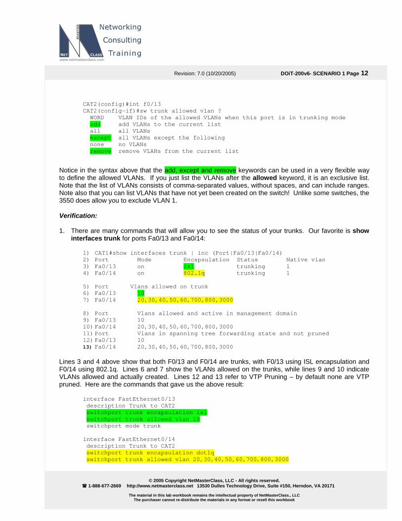
CAT2(config)#int f0/13
CAT2(config-if)#sw trunk allowed vlan ? WORD VLAN IDs of the allowed VLANs when this port is in trunking mode add add VLANs to the current list all all VLANs except all VLANs except the following none no VLANs remove remove VLANs from the current list
Notice i syntax above that the add, except and remove keywords can be used in a very flexible way
Not355
erification:
1. The the status of your trunks. Our favorite is show inte
t|Fa0/13|Fa0/14) Status Native vlan
n the to define the allowed VLANs. If you just list the VLANs after the allowed keyword, it is an exclusive list. Note that the list of VLANs consists of comma-separated values, without spaces, and can include ranges.
e also that you can list VLANs that have not yet been created on the switch! Unlike some switches, the 0 does allow you to exclude VLAN 1.
V
re are many commands that will allow you to seerfaces trunk for ports Fa0/13 and Fa0/14:
1) CAT1#show interfaces trunk | inc (Por2) Port Mode Encapsulation3) Fa0/13 on isl trunking 1 4) Fa0/14 on 802.1q tr
unking 1
Port Vlans allowed on trunk 5)6) Fa0/13 10 7) Fa0/14 20,30,40,50,60,700,800,3000
8) Port Vlans allowed and active in management domain 9) Fa0/13 10 10) Fa0/14 20,30,40,50,60,700,800,3000 1) Port Vlans in spanning tree forwarding state and not pruned
0/13 10 13) Fa0/14 20,30,40,50,60,700,800,3000
Line are trunks, with F0/13 using ISL encapsulation and 0/14 using 802.1q. Lines 6 and 7 show the VLANs allowed on the trunks, while lines 9 and 10 indicate
VLANs none are VTP pruned. He
112) Fa
s 3 and 4 above show that both F0/13 and F0/14
Fallowed and actually created. Lines 12 and 13 refer to VTP Pruning – by default
re are the commands that gave us the above result: interface FastEthernet0/13 description Trunk to CAT2 switchport trunk encapsulation isl switchport trunk allowed vlan 10 switchport mode trunk t net0/14 in erface FastEther
description Trunk to CAT2 switchport trunk encapsulation dot1q switchport trunk allowed vlan 20,30,40,50,60,700,800,3000
Revision: 7.0 (10/20/2005) DOiT-200v6- SCENARIO 1 Page 13
© 2005 Copyright NetMasterClass, LLC - All rights reserved.
1-888-677-2669 http://www.netmasterclass.net 13530 Dulles Technology Drive, Suite #150, Herndon, VA 20171
The material in this lab workbook remains the intellectual property of NetMasterClass., LLC The purchaser cannot re-distribute the materials in any format or resell this workbook
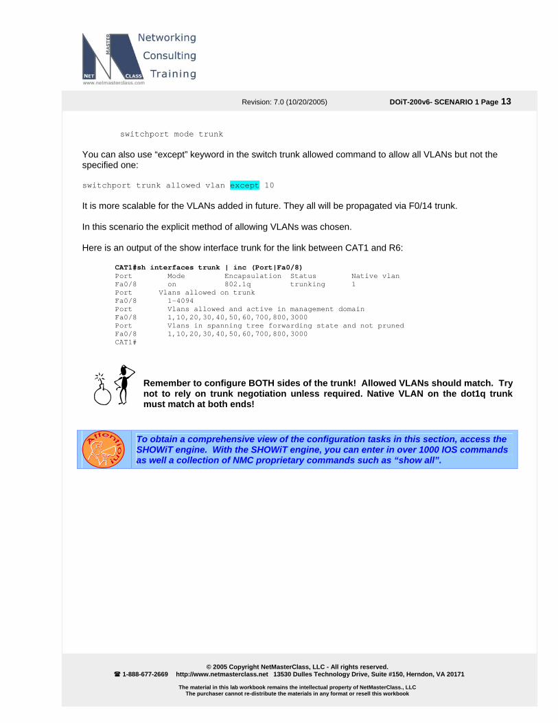
switchport mode trunk You can also use “except” keyword in the switch trunk allowed command to allow all VLANs but not the specified one: switchport trunk allowed vlan except 10 It is mor future. They all will be propagated via F0/14 trunk. In this s s was chosen. Here is e trunk for the link between CAT1 and R6:
(Port|Fa0/8) us Native vlan
Port Vlans allowed and active in management domain
1,10,20,30,40,50,60,700,800,3000
Remember to configure BOTH sides of the trunk! Allowed VLANs should match. Try e VLAN on the dot1q trunk
must match at both ends!
e scalable for the VLANs added in
cenario the explicit method of allowing VLAN
an output of the show interfac CAT1#sh interfaces trunk | inc Port Mode Encapsulation StatFa0/8 on 802.1q trunking 1
n trunk Port Vlans allowed oFa0/8 1-4094
Fa0/8 1,10,20,30,40,50,60,700,800,3000 Port Vlans in spanning tree forwarding state and not pruned Fa0/8 CAT1#
not to rely on trunk negotiation unless required. Nativ
To obtain a comprehensive view of the configuration tasks in this section, access the SHOWiT engine. With the SHOWiT engine, you can enter in over 1000 IOS commands as well a collection of NMC proprietary commands such as “show all”.

Revision: 7.0 (10/20/2005) DOiT-200v6- SCENARIO 1 Page 14
© 2005 Copyright NetMasterClass, LLC - All rights reserved.
1-888-677-2669 http://www.netmasterclass.net 13530 Dulles Technology Drive, Suite #150, Herndon, VA 20171
The material in this lab workbook remains the intellectual property of NetMasterClass., LLC The purchaser cannot re-distribute the materials in any format or resell this workbook
HIDDEN ISSUES TO SPOT WITH ROUTE REDISTRIBUTION Before examining the specific issues related to configuring each of the IGP’s involved in this Scenario, let’s survey the entire topology and determine how all of the different IGP’s will interoperate. Performing such a survey will force us to consider the issues related to route redistribution. When evaluating a single internetwork topology that contains multiple routing protocols, a good starting point of analysis is to determine whether there is more than one direct or indirect connecting point between two routing protocols. If there is only one connecting point between two routing protocols, providing connectivity between them is relatively simple. If there are two or more connecting points, then providing connectivity between the two routing protocols can be complex. When two or more connecting points exist, you can use them to provide redundancy as well as load balancing and optimum path selection. However, when two or more connecting points exist, you must also assure, at the very least, that no routing loops exist and, whenever possible, no suboptimal paths are selected. When evaluating this Scenario’s internetwork topology, how the routing protocols have been assigned to it and where are the specified redistribution points you will see that there exist at least two possible paths to reach many of the IP addresses assigned in the Scenario. Of the two possible paths, one path traverses the OSPF domain and the second traverses the RIP v2 domain. Therefore, the only routing protocols providing transit services in this Scenario are OSPF and RIP v2. The protocols EIGRP, RIP v2 (second domain between R2 and CAT1) are deployed on the edge of the Scenario topology. The Scenario topology is represented in the following diagram: NOTE: The colors used in this diagram greatly add to the understanding of redistribution applied to this Scenario. If you print this document, attempt to print this page with a color printer.

Revision: 7.0 (10/20/2005) DOiT-200v6- SCENARIO 1 Page 15
© 2005 Copyright NetMasterClass, LLC - All rights reserved.
1-888-677-2669 http://www.netmasterclass.net 13530 Dulles Technology Drive, Suite #150, Herndon, VA 20171
The material in this lab workbook remains the intellectual property of NetMasterClass., LLC The purchaser cannot re-distribute the materials in any format or resell this workbook
OSP
F A
0
A 20
50.*/30105.0/25CAT2 R5
R2 R3
R1 R4
R6 FRS
OSPF A 0
OSPF A 14
RIP
V2
CAT1
OSPF A16
OSPF A67
A 10
RIP
V2
RIP OSPF
RIP OSPF
RIP OSPF
RIP EIGRP
EIGRP OSPF
50.*/30
SUMMARY
50.0/24
105.0/24
option1
SUMMARY50.0/24105.0/24option1
CONN OSPF
EIG
RP
AS
100
VLCONN OSPFA 16
EIGRP AS1 OSPF
Loopback
Mutual redistribution, eg. EIGRP and OSPF
CONNOne way
redistribution, eg. CONNECTED into
OSPF
Prefix injection
OSPF
R Router
EIGRP
RIP
OSPF
Legend
Trash can
See the scenario master diagram and VLAN table for data link details!
Revision: 7.0 (10/20/2005) DOiT-200v6- SCENARIO 1 Page 16
© 2005 Copyright NetMasterClass, LLC - All rights reserved.
1-888-677-2669 http://www.netmasterclass.net 13530 Dulles Technology Drive, Suite #150, Herndon, VA 20171
The material in this lab workbook remains the intellectual property of NetMasterClass., LLC The purchaser cannot re-distribute the materials in any format or resell this workbook
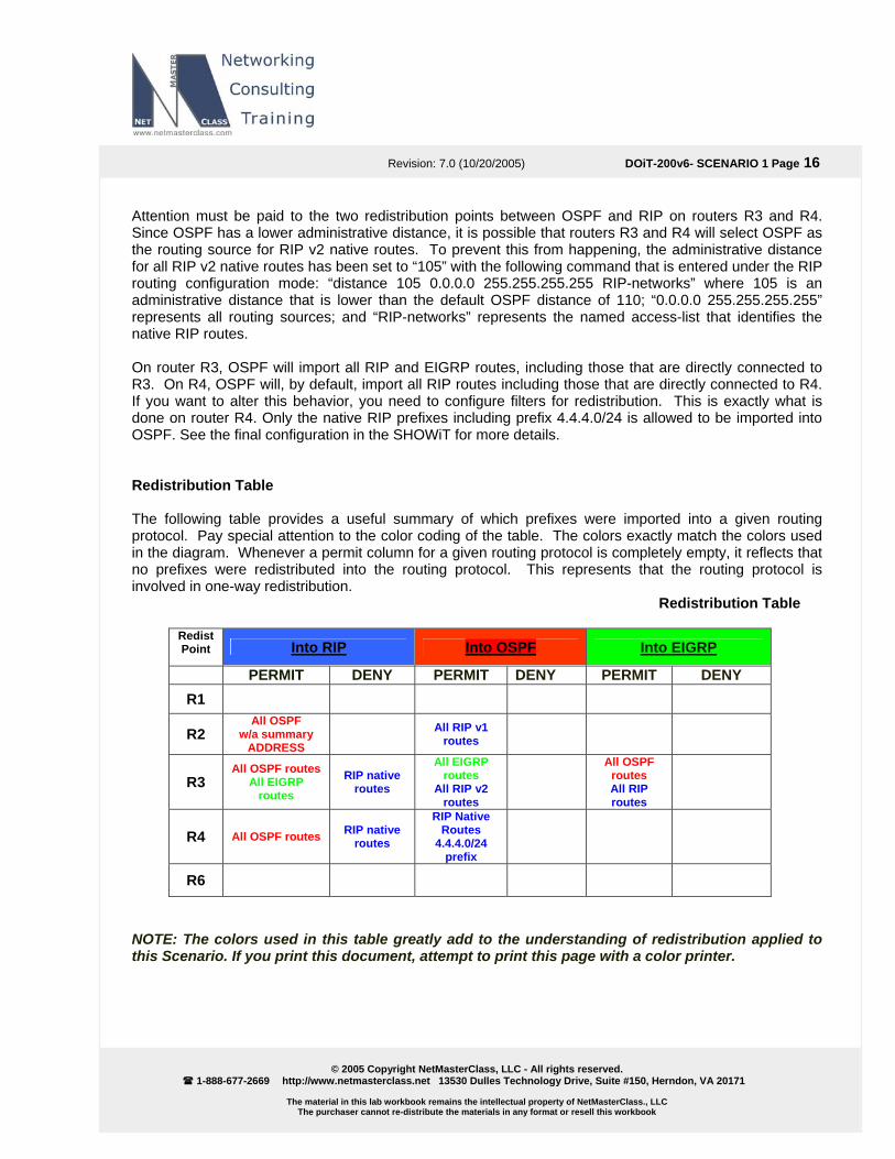
Attention must be paid to the two redistribution points between OSPF and RIP on routers R3 and R4. Since OSPF has a lower administrative distance, it is possible that routers R3 and R4 will select OSPF as the routing source for RIP v2 native routes. To prevent this from happening, the administrative distance for all RIP v2 native routes has been set to “105” with the following command that is entered under the RIP routing configuration mode: “distance 105 0.0.0.0 255.255.255.255 RIP-networks” where 105 is an administrative distance that is lower than the default OSPF distance of 110; “0.0.0.0 255.255.255.255” represents all routing sources; and “RIP-networks” represents the named access-list that identifies the native RIP routes. On router R3, OSPF will import all RIP and EIGRP routes, including those that are directly connected to R3. On R4, OSPF will, by default, import all RIP routes including those that are directly connected to R4. If you want to alter this behavior, you need to configure filters for redistribution. This is exactly what is done on router R4. Only the native RIP prefixes including prefix 4.4.4.0/24 is allowed to be imported into OSPF. See the final configuration in the SHOWiT for more details. Redistribution Table The following table provides a useful summary of which prefixes were imported into a given routing protocol. Pay special attention to the color coding of the table. The colors exactly match the colors used in the diagram. Whenever a permit column for a given routing protocol is completely empty, it reflects that no prefixes were redistributed into the routing protocol. This represents that the routing protocol is involved in one-way redistribution. Redistribution Table
Redist Point Into RIP Into OSPF Into EIGRP
PERMIT DENY PERMIT DENY PERMIT DENY R1
R2 All OSPF
w/a summary ADDRESS
All RIP v1 routes
R3 All OSPF routes
All EIGRP routes
RIP native routes
All EIGRP routes
All RIP v2 routes
All OSPF
routes All RIP routes
R4 All OSPF routes RIP native routes
RIP Native Routes
4.4.4.0/24 prefix
R6
NOTE: The colors used in this table greatly add to the understanding of redistribution applied to this Scenario. If you print this document, attempt to print this page with a color printer.
Revision: 7.0 (10/20/2005) DOiT-200v6- SCENARIO 1 Page 17
© 2005 Copyright NetMasterClass, LLC - All rights reserved.
1-888-677-2669 http://www.netmasterclass.net 13530 Dulles Technology Drive, Suite #150, Herndon, VA 20171
The material in this lab workbook remains the intellectual property of NetMasterClass., LLC The purchaser cannot re-distribute the materials in any format or resell this workbook
1.3 OSPF
HIDDEN ISSUES TO SPOT WITH THE OSPF CONFIGURATION Issue: On area 0, use the OSPF network type which forces DR and BDR election but uses unicast packets for Hello and Database Exchange. Solution: The OSPF network type “non-broadcast” is the right answer. With the non-broadcast network type, the DR/BDR election requirement is fulfilled, and unicast packets will be used for hello’s and LSA database exchange. Check out the OSPF Network Type Table in Appendix D of the DOiT-200v6 workbook. Issue: Placement of the Designated Router (DR). Solution:
1. OSPF hellos have a TTL of 1, and the Frame-Relay hub router decrements the TTL when the Hello goes from one DLCI to another. So hellos cannot go from one Frame-Relay spoke router to another. We can make OSPF work on a Frame-Relay hub and spoke topology by making sure that the DR is at the hub router. That way, all of the routers forming adjacencies with the DR are within one hop.
2. The interface-level command ip ospf priority controls the DR election process. The default
priority is 1, and the interface with the highest priority becomes the DR for the link. We can make an interface totally ineligible to become a DR or BDR by setting the interface priority to 0.
3. Due to the use of unicast hellos, neighbor statements are required with the non-broadcast network
type. The neighbor statements are not required on routers that are configured with ip ospf priority 0. So we only need to put the neighbor statements on R1, the frame-relay hub and OSPF Designated Router.
Verification:
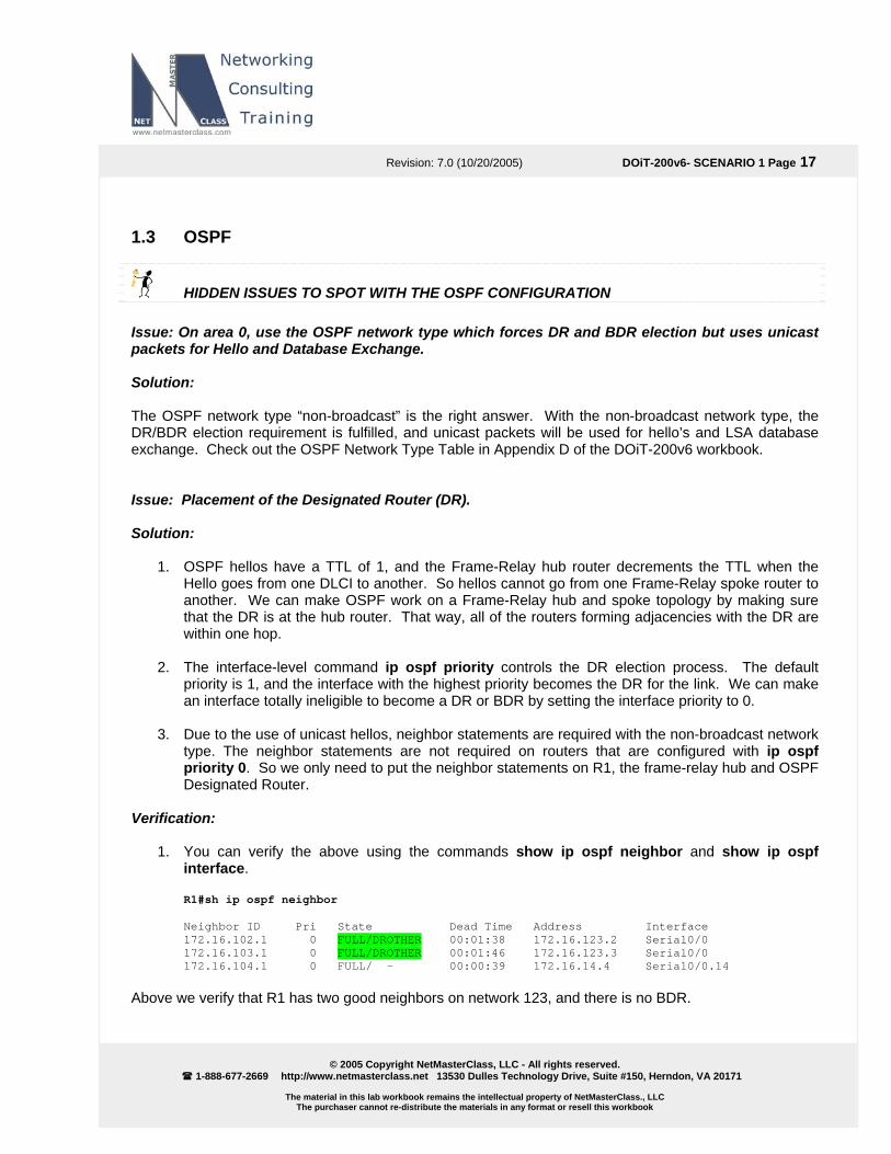
1. You can verify the above using the commands show ip ospf neighbor and show ip ospf interface.
R1#sh ip ospf neighbor Neighbor ID Pri State Dead Time Address Interface 172.16.102.1 0 FULL/DROTHER 00:01:38 172.16.123.2 Serial0/0 172.16.103.1 0 FULL/DROTHER 00:01:46 172.16.123.3 Serial0/0 172.16.104.1 0 FULL/ - 00:00:39 172.16.14.4 Serial0/0.14
Above we verify that R1 has two good neighbors on network 123, and there is no BDR.

Revision: 7.0 (10/20/2005) DOiT-200v6- SCENARIO 1 Page 18
© 2005 Copyright NetMasterClass, LLC - All rights reserved.
1-888-677-2669 http://www.netmasterclass.net 13530 Dulles Technology Drive, Suite #150, Herndon, VA 20171
The material in this lab workbook remains the intellectual property of NetMasterClass., LLC The purchaser cannot re-distribute the materials in any format or resell this workbook
Below we verify that R1 is the DR, that the OSPF network type is Non-Broadcast, and that we have no BDR and two good adjacencies:
R1#sh ip ospf int s0/0 Serial0/0 is up, line protocol is up Internet Address 172.16.123.1/24, Area 0 Process ID 1, Router ID 172.16.101.1, Network Type NON_BROADCAST, Cost: 64 Transmit Delay is 1 sec, State DR, Priority 1 Designated Router (ID) 172.16.101.1, Interface address 172.16.123.1 No backup designated router on this network Timer intervals configured, Hello 30, Dead 120, Wait 120, Retransmit 5 oob-resync timeout 120 Hello due in 00:00:05 Index 2/5, flood queue length 0 Next 0x0(0)/0x0(0) Last flood scan length is 4, maximum is 13 Last flood scan time is 0 msec, maximum is 4 msec Neighbor Count is 2, Adjacent neighbor count is 2 Adjacent with neighbor 172.16.102.1 Adjacent with neighbor 172.16.103.1 Suppress hello for 0 neighbor(s)
Issue: In Task 1.4.3, Use the best matching OSPF network type for the 172.16.14.0/24 subnet Solution: Since there are only two OSPF routers on this segment, the point-to-point OSPF network type is the best match. Also, one of the two routers on this segment is assigned the OSPF point-to-point network type by default (the R1 interface.) On R4 we go into interface S0/0 and enter ip ospf network point-to-point. Again, we can verify with the show ip ospf interface command. Note that the OSPF network type and the Frame-Relay interface type do not have to match. The only combination that won’t work is trying to use a point-to-point OSPF network type on a Frame-Relay interface that actually has multiple DLCI’s.
Remember that OSPF network types should be the same on all frame-relay interfaces in a particular subnet. Exception is point-to-point and point-to-multipoint network types assuming that the timers are changed to match.
Issue: Advertise loopback 172.16.103.1/32 in OSPF from R3 without adding it in any area and without redistribution connected prefixes. It should appear in the routing tables of the OSPF speakers as type E2 Solution: If it is going to be added to OSPF without being assigned to an OSPF area, it must be injected into OSPF as an External LSA, so it will have to be redistributed into OSPF. The scenario rules out the redistribute connected as well. When you read ahead in this Scenario, you notice that RIP and EIGRP are also running on router R3. These two routing protocols can be used to redistribute the 172.16.103.0/24 prefix into OSPF. However, when you examine the EIGRP configuration tasks, it is utilizing the “mask” option on

Revision: 7.0 (10/20/2005) DOiT-200v6- SCENARIO 1 Page 19
© 2005 Copyright NetMasterClass, LLC - All rights reserved.
1-888-677-2669 http://www.netmasterclass.net 13530 Dulles Technology Drive, Suite #150, Herndon, VA 20171
The material in this lab workbook remains the intellectual property of NetMasterClass., LLC The purchaser cannot re-distribute the materials in any format or resell this workbook
the EIGRP network statement to restrict only a single prefix – 172.16.35.0/24 – to be included in the EIGRP process on router R3. As a result, all other 172.16.0.0 subnets are excluded from EIGRP on router R3. With the RIP configuration on R3 (as with any RIP configuration), there is no “mask” option associated with the network statement. Under the RIP router configuration mode, you can only specify network statements with a classful network. Therefore, when you redistribute RIP into OSPF on router R3, the 172.16.103.0/24 network will be injected into OSPF as an external network. Through the redistribution of RIP into OSPF, the requirements of this task can be fulfilled. Verification: On R1, you could enter the command show ip route | include E2. The network 172.16.103.1/32 should show up in the routing table as an OSPF External Type 2 route. Alternatively, you could examine the OSPF database on R3, part of which is shown below.
R3#sh ip ospf database external LS age: 745 Options: (No TOS-capability, DC) LS Type: AS External Link Link State ID: 172.16.103.1 (External Network Number ) Advertising Router: 172.16.103.1 LS Seq Number: 80000050 Checksum: 0xDB2B Length: 36 Network Mask: /32 Metric Type: 2 (Larger than any link state path) TOS: 0 Metric: 20 Forward Address: 0.0.0.0 External Route Tag: 0
Issue: Advertise loopback 172.16.102.1/32 in OSPF area 20. Advertise loopback 172.16.101.1/32 in OSPF area 10 Solution: Configure the network statement under the router OSPF process for the specified loopback networks: R1:
router ospf 1 network 172.16.101.1 0.0.0.0 area 10
R2: router ospf 1 network 172.16.102.1 0.0.0.0 area 20
Verification: The prefixes are advertised as inter-area OSPF routes:
R3#sh ip route ospf | inc (101|102) O IA 172.16.101.1/32 [110/65] via 172.16.123.1, 05:02:01, Serial0/0 O IA 172.16.102.1/32 [110/65] via 172.16.123.2, 05:02:01, Serial0/0 R3#

Revision: 7.0 (10/20/2005) DOiT-200v6- SCENARIO 1 Page 20
© 2005 Copyright NetMasterClass, LLC - All rights reserved.
1-888-677-2669 http://www.netmasterclass.net 13530 Dulles Technology Drive, Suite #150, Herndon, VA 20171
The material in this lab workbook remains the intellectual property of NetMasterClass., LLC The purchaser cannot re-distribute the materials in any format or resell this workbook
Issue: Configure OSPF area 16 and area 67 on the 172.16.16.0/24 and 172.16.67.0/24 respectively. Advertise the Loopback network 172.16.107.1/32 as E2 with the initial metric 100 and tag 200 Solution: The OSPF area 67 is not attached to the OSPF backbone area 0, look at the IPv4 IGP diagram. You need to configure a virtual link to connect the area 67 to area 0. Configure redistribute connected to advertise the loopback 107 network from the FRS as external OSPF prefix. In the redistribute statement you can set the metric-type to 2 (E2 is default), metric to 100 and tag to 200: R1:
router ospf 1 area 16 virtual-link 172.16.106.1 network 172.16.16.0 0.0.0.255 area 16
R6:
router ospf 1 area 16 virtual-link 172.16.101.1 network 172.16.16.0 0.0.0.255 area 16 network 172.16.67.0 0.0.0.255 area 67
FRS:
router ospf 1 log-adjacency-changes redistribute connected metric 100 subnets tag 200 route-map CONNECTED network 172.16.67.0 0.0.0.255 area 67 ! ip access-list standard CONNECTED permit 172.16.107.0 0.0.0.255
We used the route-map as a general practice to limit the redistribute connected only to the loopback 107. It is not necessary for this scenario. Verification: Verification of the OSPF neighbors is done on R6, the output shows FULL adjacency:
R6#sh ip ospf neighbor Neighbor ID Pri State Dead Time Address Interface 172.16.101.1 0 FULL/ - - 172.16.16.1 OSPF_VL0 172.16.101.1 1 FULL/BDR 00:00:17 172.16.16.1 FastEthernet0/0.40 172.16.67.7 1 FULL/BDR 00:00:30 172.16.67.7 FastEthernet0/0.3000 R6# R6#show ip route 172.16.107.1 Routing entry for 172.16.107.1/32 Known via "ospf 1", distance 110, metric 100 Tag 200, type extern 2, forward metric 1 Last update from 172.16.67.7 on FastEthernet0/0.3000, 00:33:18 ago Routing Descriptor Blocks: * 172.16.67.7, from 172.16.67.7, 00:33:18 ago, via FastEthernet0/0.3000 Route metric is 100, traffic share count is 1 Route tag 200 R6#

Revision: 7.0 (10/20/2005) DOiT-200v6- SCENARIO 1 Page 21
© 2005 Copyright NetMasterClass, LLC - All rights reserved.
1-888-677-2669 http://www.netmasterclass.net 13530 Dulles Technology Drive, Suite #150, Herndon, VA 20171
The material in this lab workbook remains the intellectual property of NetMasterClass., LLC The purchaser cannot re-distribute the materials in any format or resell this workbook
Issue: Set the dead interval to 20 seconds for the OSPF adjacency over the 172.16.16.0/24 link. Do not configure ip ospf dead-interval interface command to accomplish this task Solution: The OSPF interface dead interval can be changed implicitly by changing the hello interval. The OSPF hello dead interval is four times of hello interval, therefore if you assign 5 to hello interval the IOS will calculate and change the dead interval to 20: Verification: We’ll show the output on R1 , the R6’s output is similar:
R1#show run int fa0/0 Building configuration... Current configuration : 122 bytes ! interface FastEthernet0/0 ip address 172.16.16.1 255.255.255.0 ip ospf hello-interval 5 duplex auto speed auto end R1#show ip ospf int fa0/0 FastEthernet0/0 is up, line protocol is up Internet Address 172.16.16.1/24, Area 16 Process ID 1, Router ID 172.16.101.1, Network Type BROADCAST, Cost: 1 Transmit Delay is 1 sec, State BDR, Priority 1 Designated Router (ID) 172.16.106.1, Interface address 172.16.16.6 Backup Designated router (ID) 172.16.101.1, Interface address 172.16.16.1 Timer intervals configured, Hello 5, Dead 20, Wait 20, Retransmit 5 oob-resync timeout 40 Hello due in 00:00:02 Supports Link-local Signaling (LLS) Index 1/5, flood queue length 0 Next 0x0(0)/0x0(0) Last flood scan length is 2, maximum is 6 Last flood scan time is 0 msec, maximum is 4 msec Neighbor Count is 1, Adjacent neighbor count is 1 Adjacent with neighbor 172.16.106.1 (Designated Router) Suppress hello for 0 neighbor(s) R1#
To obtain a comprehensive view of the configuration tasks in this section, access the SHOWiT engine. With the SHOWiT engine, you can enter in over 1000 IOS commands as well a collection of NMC proprietary commands such as “show all”.

Revision: 7.0 (10/20/2005) DOiT-200v6- SCENARIO 1 Page 22
© 2005 Copyright NetMasterClass, LLC - All rights reserved.
1-888-677-2669 http://www.netmasterclass.net 13530 Dulles Technology Drive, Suite #150, Herndon, VA 20171
The material in this lab workbook remains the intellectual property of NetMasterClass., LLC The purchaser cannot re-distribute the materials in any format or resell this workbook
1.4 RIP
HIDDEN ISSUES TO SPOT WITH THE RIP CONFIGURATION Issue: Configure only RIP version 2… Solution: By default RIP routing process supports two versions 1 and 2, the interfaces send RIP updates version 1 and listen to both version. Here is an example of show ip protocols command displaying the interfaces involved in the RIP exchange when RIP is configured by default:
Default version control: send version 1, receive any version Interface Send Recv Triggered RIP Key-chain FastEthernet0/0 1 1 2 Serial0/0 1 1 2
You need to configure version 2 under the rip process to send and receive only version 2 RIP updates:
router rip version 2
Default version control: send version 2, receive version 2 Interface Send Recv Triggered RIP Key-chain FastEthernet0/1 2 2
Issue: Advertise the following loopback interfaces on CAT1 … Solution: You do not have to do anything special to advertise the loopbacks, they are already added in the RIP database with the network 172.16.0.0 statement. Issue: Make sure that router CAT2 receives only /24 and /32 prefixes. Do not use any filtering to accomplish this task. CAT2 is configured as a RIP speaking router. All routing information it learns originates from its neighbor R2 over the 172.16.20.0/24 subnet. R2 is redistributing OSPF routes into RIP. The task says that you are not allowed to bring other prefixes to CAT2. The problem with that is that there are prefixes /25 and /30 that are originated somewhere in the network, and those prefixes are not allowed to reach CAT2. In this case, R2 could’ve originated a default route, but the 0.0.0.0 is explicitly prohibited in this scenario, please see the goals and restrictions at the beginning of the scenario.

Revision: 7.0 (10/20/2005) DOiT-200v6- SCENARIO 1 Page 23
© 2005 Copyright NetMasterClass, LLC - All rights reserved.
1-888-677-2669 http://www.netmasterclass.net 13530 Dulles Technology Drive, Suite #150, Herndon, VA 20171
The material in this lab workbook remains the intellectual property of NetMasterClass., LLC The purchaser cannot re-distribute the materials in any format or resell this workbook
Solution 1 provided in the Answer Key: The problem can be solved by summarizing the /25 and /30 subnets to respective /24 summaries into OSPF. Which router or “routers” should generate the /24 summary for the 172.16.50.X/30 prefixes? In order to provide the highest level of redundancy, both routers R3 and R4 should be configured to generate the summary. See the redistribution diagram in the Redistribution section. Discard-Route Issues When you create these in OSPF a summary address acting as the “discard-route” will be created on both routers R3 and R4 pointing to a Null interface. These summary routes created on routers R3 and R4 will use the local “bit bucket” created by the null interface for all non-existent destination addresses that match the summaries. There is an option in OSPF to create a summary address without creating a local summary routing table entry pointing to a null interface by configuring the OSPF router configuration command no discard-route. If you use the no discard-route command, a routing loop may result between routers R3 and R4. With the “no discard-route internal” command configured on both routers R3 and R4, both routers R3 and R4 will learn the summary address from each other. If an unassigned IP address from the 172.16.50.X/24 address space is received by either R3 or R4 these packets will bounce between the two routers. In order to eliminate this looping condition, prevent the RIP learned summary-address from being installed in the routing tables of both R3 and R4 by configuring either one of the two commands: (1) a distribute-list in command referencing the summary address or (2) a distance command referencing only the summary-address with the distance set to 255. In the exercise, we have simply permitted the discard routes to null 0 to be placed in the tables of R3 and R4. Solution 2 (an alternative solution not included in the Answer Key). Instead of summarizing into OSPF as described above, you could configure a RIP summary prefix 172.16.50.0./24 on the FastEthernet interface of R2. RIP version 2 will advertise a /24 prefix from R2 to CAT2. The command would simply be ip summary-address rip 172.16.50.0 255.255.255.0 Issue: Multiple Redistribution Points between OSPF and RIP v.2. Two redistribution points exist between RIP v.2 and OSPF, on routers R3 and R4. All RIP routes originating from CAT1 will be assigned the administrative distance of 120 when routers R3 and R4 receive them. These same routes will get redistributed into OSPF at both routers R3 and R4. When they are flooded through the OSPF domain, they will make it back to R3 and R4 as external OSPF routes. Since OSPF has a lower administrative distance than RIP, routers R3 and R4 will select an OSPF path for a RIP prefix even though they are directly connected to the RIP domain. This is a complex hidden issue, but it is well described and documented in the following Tech-Note residing in the NetMasterClass web-site technical library: “A Scenario with Multiple Redistribution Points”. Solution: Adjust the administrative distance for all native RIP routes originating from CAT1 to a value lower than the default administrative distance of OSPF, which is 110. The command would be as follows on R3, for

Revision: 7.0 (10/20/2005) DOiT-200v6- SCENARIO 1 Page 24
© 2005 Copyright NetMasterClass, LLC - All rights reserved.
1-888-677-2669 http://www.netmasterclass.net 13530 Dulles Technology Drive, Suite #150, Herndon, VA 20171
The material in this lab workbook remains the intellectual property of NetMasterClass., LLC The purchaser cannot re-distribute the materials in any format or resell this workbook
example, under the RIP process. The command sets the distance to 105 for all prefixes identified in the named access-list RIP-networks learned from any RIP source (0.0.0.0 255.255.255.255).
distance 105 0.0.0.0 255.255.255.255 RIP-networks Verification: On routers R3 and R4 issue show ip route rip, and make sure native RIP prefixes are routed by RIP.
R3#show ip route rip 4.0.0.0/24 is subnetted, 1 subnets R 4.4.4.0 [105/1] via 172.16.34.4, 00:00:09, FastEthernet0/1 172.16.0.0/16 is variably subnetted, 24 subnets, 4 masks R 172.16.110.128/25 [105/1] via 172.16.34.10, 00:00:10, FastEthernet0/1 R 172.16.50.12/30 [105/1] via 172.16.34.10, 00:00:10, FastEthernet0/1 R 172.16.50.8/30 [105/1] via 172.16.34.10, 00:00:10, FastEthernet0/1 R 172.16.50.4/30 [105/1] via 172.16.34.10, 00:00:10, FastEthernet0/1 R 172.16.104.1/32 [105/1] via 172.16.34.4, 00:00:09, FastEthernet0/1 R3# R4#sh ip ro rip 172.16.0.0/16 is variably subnetted, 24 subnets, 4 masks R 172.16.110.128/25 [105/1] via 172.16.34.10, 00:00:25, FastEthernet0/0 R 172.16.50.12/30 [105/1] via 172.16.34.10, 00:00:25, FastEthernet0/0 R 172.16.50.8/30 [105/1] via 172.16.34.10, 00:00:25, FastEthernet0/0 R 172.16.50.4/30 [105/1] via 172.16.34.10, 00:00:25, FastEthernet0/0 R 172.16.50.24/30 [105/1] via 172.16.34.3, 00:00:17, FastEthernet0/0 R 172.16.50.20/30 [105/1] via 172.16.34.3, 00:00:17, FastEthernet0/0 R 172.16.50.16/30 [105/1] via 172.16.34.3, 00:00:17, FastEthernet0/0 R 172.16.35.0/24 [105/1] via 172.16.34.3, 00:00:17, FastEthernet0/0 R 172.16.105.0/25 [105/1] via 172.16.34.3, 00:00:17, FastEthernet0/0 R 172.16.105.0/24 [105/1] via 172.16.34.3, 00:00:17, FastEthernet0/0 R 172.16.103.1/32 [105/1] via 172.16.34.3, 00:00:17, FastEthernet0/0 R4#
Notice, the scenario configured that R4 prefer the EIGRP originated prefixes via RIP over the Ethernet link. Check the SHOWiT for the configuration details.
To obtain a comprehensive view of the configuration tasks in this section, access the SHOWiT engine. With the SHOWiT engine, you can enter in over 1000 IOS commands as well a collection of NMC proprietary commands such as “show all”.

Revision: 7.0 (10/20/2005) DOiT-200v6- SCENARIO 1 Page 25
© 2005 Copyright NetMasterClass, LLC - All rights reserved.
1-888-677-2669 http://www.netmasterclass.net 13530 Dulles Technology Drive, Suite #150, Herndon, VA 20171
The material in this lab workbook remains the intellectual property of NetMasterClass., LLC The purchaser cannot re-distribute the materials in any format or resell this workbook
1.5 EIGRP
HIDDEN ISSUES TO SPOT WITH THE EIGRP CONFIGURATION Issue: Configure EIGRP AS 100 between R3 and R5. Configure only a single network 172.16.35.0 0.0.0.255 statement under the EIGRP routing process. Solution: Use the EIGRP network/mask router configuration command to limit the number of interfaces that are participating in EIGRP on routers R3 and R5. If you configure EIGRP with the classful network command – “network 172.16.0.0” – all interfaces assigned with 172.16.0.0 will be included within EIGRP. As a general practice, use the mask option when configuring a network command under the EIGRP process to gain greater control over what interfaces are participating in EIGRP, otherwise use the major network notation to add all interfaces belonging to that major network to the EIGRP topology. Issue: Advertising a range of 172.16.50.XX/30 subnets on router R5. Solution: It creates an issue for the RIP domain between R2 and CAT2. For more details on the solution check the RIP section of this document. Issue: Detect the neighbor loss twice as fast as the default between R3 and R5. Solution: EIGRP hello packets are multicasted every 5 seconds on an Ethernet segment. By default, the EIGRP hold timer is 3 times the hello interval. Therefore, the EIGRP hold timer for an Ethernet segment is 15 seconds. You can change these timers with the following two interface commands: ip hello-interval eigrp 100 2 and ip hold-time eigrp 100 6. Note that changing the hello timer does not automatically change the advertised holdtime as is was in OSPF. Verification: You could verify the hello interval by doing debug ip packet and noting the frequency of packets to the EIGRP reserved multicast address 224.0.0.10. Also you see the hello interval in the output of show ip eigrp interface detail.
R5#sh ip eigrp interfaces detail fastEthernet 0/0 IP-EIGRP interfaces for process 100 Xmit Queue Mean Pacing Time Multicast Pending Interface Peers Un/Reliable SRTT Un/Reliable Flow Timer Routes Fa0/0 1 0/0 1 0/10 50 0 Hello interval is 2 sec Next xmit serial <none> Un/reliable mcasts: 0/83 Un/reliable ucasts: 143/61 Mcast exceptions: 0 CR packets: 0 ACKs suppressed: 3 Retransmissions sent: 2 Out-of-sequence rcvd: 0
Revision: 7.0 (10/20/2005) DOiT-200v6- SCENARIO 1 Page 26
© 2005 Copyright NetMasterClass, LLC - All rights reserved.
1-888-677-2669 http://www.netmasterclass.net 13530 Dulles Technology Drive, Suite #150, Herndon, VA 20171
The material in this lab workbook remains the intellectual property of NetMasterClass., LLC The purchaser cannot re-distribute the materials in any format or resell this workbook
Authentication mode is not set R5#
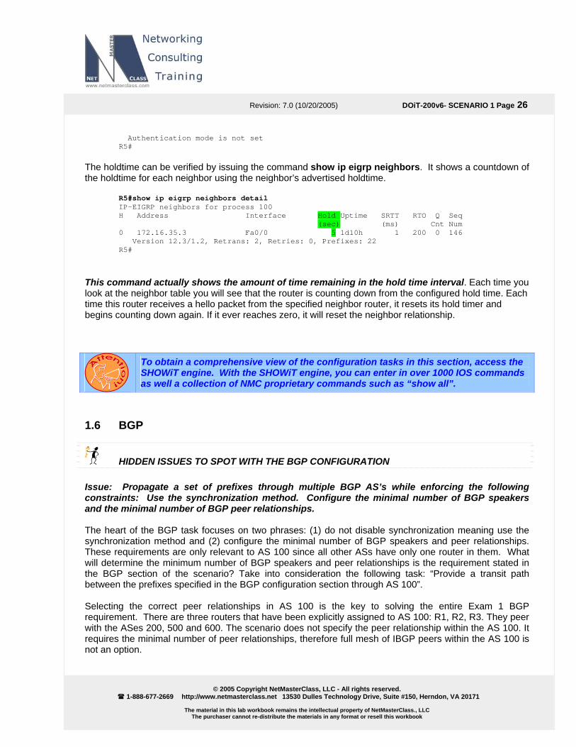
The holdtime can be verified by issuing the command show ip eigrp neighbors. It shows a countdown of the holdtime for each neighbor using the neighbor’s advertised holdtime.
R5#show ip eigrp neighbors detail IP-EIGRP neighbors for process 100 H Address Interface Hold Uptime SRTT RTO Q Seq (sec) (ms) Cnt Num 0 172.16.35.3 Fa0/0 5 1d10h 1 200 0 146 Version 12.3/1.2, Retrans: 2, Retries: 0, Prefixes: 22 R5#
This command actually shows the amount of time remaining in the hold time interval. Each time you look at the neighbor table you will see that the router is counting down from the configured hold time. Each time this router receives a hello packet from the specified neighbor router, it resets its hold timer and begins counting down again. If it ever reaches zero, it will reset the neighbor relationship.
To obtain a comprehensive view of the configuration tasks in this section, access the SHOWiT engine. With the SHOWiT engine, you can enter in over 1000 IOS commands as well a collection of NMC proprietary commands such as “show all”.
1.6 BGP
HIDDEN ISSUES TO SPOT WITH THE BGP CONFIGURATION Issue: Propagate a set of prefixes through multiple BGP AS’s while enforcing the following constraints: Use the synchronization method. Configure the minimal number of BGP speakers and the minimal number of BGP peer relationships. The heart of the BGP task focuses on two phrases: (1) do not disable synchronization meaning use the synchronization method and (2) configure the minimal number of BGP speakers and peer relationships. These requirements are only relevant to AS 100 since all other ASs have only one router in them. What will determine the minimum number of BGP speakers and peer relationships is the requirement stated in the BGP section of the scenario? Take into consideration the following task: “Provide a transit path between the prefixes specified in the BGP configuration section through AS 100”. Selecting the correct peer relationships in AS 100 is the key to solving the entire Exam 1 BGP requirement. There are three routers that have been explicitly assigned to AS 100: R1, R2, R3. They peer with the ASes 200, 500 and 600. The scenario does not specify the peer relationship within the AS 100. It requires the minimal number of peer relationships, therefore full mesh of IBGP peers within the AS 100 is not an option.

Revision: 7.0 (10/20/2005) DOiT-200v6- SCENARIO 1 Page 27
© 2005 Copyright NetMasterClass, LLC - All rights reserved.
1-888-677-2669 http://www.netmasterclass.net 13530 Dulles Technology Drive, Suite #150, Herndon, VA 20171
The material in this lab workbook remains the intellectual property of NetMasterClass., LLC The purchaser cannot re-distribute the materials in any format or resell this workbook
Solution: One possible solution is shown in the diagram below. Only routers R1, R2 and R3 are configured as BGP speakers in AS 100. To ensure the minimal number of BGP peer relationships are formed either a route-reflector or a confederation could be considered for AS 100. It would be difficult to get a route-reflector solution to work in this scenario because synchronization must be enabled, and the underlying IGP is OSPF. When this is the case the RID of the OSPF router acting as the ASBR for the redistributed BGP routes must also be the RID of the advertising IBGP speaker for the same prefix. The route-reflector cluster-list should match the two previously mentioned RIDS as well. Making the OSPF ASBR, the advertising IBGP speaker and the route-reflector the same router can fulfill this; however, this will work for only a single direction of BGP updates. Any other EBGP update crossing over the AS that is not using the previously mentioned route-reflector will not meet all of the RID matching requirements. Therefore, a BGP confederation is used to minimize peering within AS 100. The BGP confederation can be configured in at least four possible ways: R1, R2 and R3 are in a separate confederation AS-s R1 is in one confederation AS, R2 and R3 is in the other R2 is in one confederation AS, R1 and R3 is in the other R3 is in one confederation AS, R1 and R2 is in the other We use the first option in this answer key. Note that only routers R1, R2 and R3 were included within the confederation. Routers R4 and CAT1 are not included as BGP speakers because they possess no EBGP neighbors, and routers R4 and CAT1 will be able to reach all externally learned BGP prefixes via OSPF since the synchronization method is used in the AS100. Check the SHOWiT engine for more configuration details.

Revision: 7.0 (10/20/2005) DOiT-200v6- SCENARIO 1 Page 28
© 2005 Copyright NetMasterClass, LLC - All rights reserved.
1-888-677-2669 http://www.netmasterclass.net 13530 Dulles Technology Drive, Suite #150, Herndon, VA 20171
The material in this lab workbook remains the intellectual property of NetMasterClass., LLC The purchaser cannot re-distribute the materials in any format or resell this workbook
Using a Confederation to Minimize Peering
Verification: Verify the synchronization on the routers in AS100 R1, R2 and R3
R1#show ip protocols | inc IGP synchronization is enabled IGP synchronization is enabled R1# R2#show ip protocols | inc IGP synchronization is enabled IGP synchronization is enabled R2# R3#show ip protocols | inc IGP synchronization is enabled IGP synchronization is enabled R3#

Revision: 7.0 (10/20/2005) DOiT-200v6- SCENARIO 1 Page 29
© 2005 Copyright NetMasterClass, LLC - All rights reserved.
1-888-677-2669 http://www.netmasterclass.net 13530 Dulles Technology Drive, Suite #150, Herndon, VA 20171
The material in this lab workbook remains the intellectual property of NetMasterClass., LLC The purchaser cannot re-distribute the materials in any format or resell this workbook
Verify the EBGP peer relationship on the routers FRS, R6, CAT2, R5:
FRS#show ip bgp summ | beg Neighbor Neighbor V AS MsgRcvd MsgSent TblVer InQ OutQ Up/Down State/PfxRcd 172.16.67.6 4 600 2760 2757 4 0 0 1d21h 3 FRS# R6#show ip bgp summ | beg Neighbor Neighbor V AS MsgRcvd MsgSent TblVer InQ OutQ Up/Down State/PfxRcd 172.16.16.1 4 100 2973 2978 12 0 0 2d01h 2 172.16.67.7 4 700 2758 2761 12 0 0 1d21h 0 R6# CAT2#show ip bgp summ | beg Neighbor Neighbor V AS MsgRcvd MsgSent TblVer InQ OutQ Up/Down State/PfxRcd 172.16.20.2 4 100 2978 2969 10 0 0 2d01h 2 CAT2# R5#show ip bgp summ | beg Neighbor Neighbor V AS MsgRcvd MsgSent TblVer InQ OutQ Up/Down State/PfxRcd 172.16.35.3 4 100 2973 2972 8 0 0 2d01h 2 R5#
Verify the AS 100 Confederation peer relationship on the routers R1, R2 and R3:
R1#show ip bgp summ | beg Neighbor Neighbor V AS MsgRcvd MsgSent TblVer InQ OutQ Up/Down State/PfxRcd 172.16.16.6 4 600 2981 2976 12 0 0 2d01h 1 172.16.102.1 4 65002 2972 2977 12 0 0 2d01h 1 172.16.103.1 4 65003 2975 2980 12 0 0 2d01h 1 R1# R2#show ip bgp summ | beg Neighbor Neighbor V AS MsgRcvd MsgSent TblVer InQ OutQ Up/Down State/PfxRcd 172.16.20.10 4 200 2972 2982 20 0 0 2d01h 1 172.16.101.1 4 65001 2978 2972 20 0 0 2d01h 2 R2# R3#show ip bgp summ | beg Neighbor Neighbor V AS MsgRcvd MsgSent TblVer InQ OutQ Up/Down State/PfxRcd 172.16.35.5 4 500 2975 2976 15 0 0 2d01h 1 172.16.101.1 4 65001 2980 2975 15 0 0 2d01h 2 R3#
Verify the BGP and OSPF prefixes on R1 and FRS:
R1#sh ip route ospf | inc 5.5.5.0|20.20.20.0 O E2 20.20.20.0 [110/1] via 172.16.123.2, 18:17:15, Serial0/0 O E2 5.5.5.0 [110/1] via 172.16.123.3, 18:17:15, Serial0/0 R1# FRS#sh ip route bgp 20.0.0.0/24 is subnetted, 1 subnets B 20.20.20.0 [20/0] via 172.16.67.6, 1d03h 5.0.0.0/24 is subnetted, 1 subnets

Revision: 7.0 (10/20/2005) DOiT-200v6- SCENARIO 1 Page 30
© 2005 Copyright NetMasterClass, LLC - All rights reserved.
1-888-677-2669 http://www.netmasterclass.net 13530 Dulles Technology Drive, Suite #150, Herndon, VA 20171
The material in this lab workbook remains the intellectual property of NetMasterClass., LLC The purchaser cannot re-distribute the materials in any format or resell this workbook
B 5.5.5.0 [20/0] via 172.16.67.6, 1d03h 6.0.0.0/24 is subnetted, 1 subnets B 6.6.6.0 [20/0] via 172.16.67.6, 1d03h FRS#
To obtain a comprehensive view of the configuration tasks in this section, access the SHOWiT engine. With the SHOWiT engine, you can enter in over 1000 IOS commands as well a collection of NMC proprietary commands such as “show all”.
1.7 IPv6
HIDDEN ISSUES TO SPOT WITH THE IPV6 CONFIGURATION Issue: You are instructed to configure site local subnet 7B between R1, R2 and R3, and use SLA number A for it. Solution: Frame Relay is configured for full mesh. However, assessment shows that only 2 PVCs are necessary to establish connectivity between R1, R2 and R3. These PVCs are already mapped to the necessary interfaces as a result of IPv4 Frame Relay task. Assigning IPv6 addresses to interfaces is a similar process; you use the ipv6 address command. R1:
ipv6 unicast routing interface Serial0/0 encapsulation frame-relay ipv6 address FEC0::A:0:0:7B:1/125 frame-relay map ipv6 FEC0::A:0:0:7B:2 102 broadcast frame-relay map ipv6 FEC0::A:0:0:7B:3 103 broadcast no frame-relay inverse-arp
R2:
ipv6 unicast routing interface Serial0/0 ipv6 address FEC0::A:0:0:7B:2/125 frame-relay map ipv6 FEC0::A:0:0:7B:1 201 broadcast frame-relay map ipv6 FEC0::A:0:0:7B:3 201 no frame-relay inverse-arp
R3:
ipv6 unicast routing interface Serial0/0 ipv6 address FEC0::A:0:0:7B:3/125 frame-relay map ipv6 FEC0::A:0:0:7B:1 301 broadcast frame-relay map ipv6 FEC0::A:0:0:7B:2 301 no frame-relay inverse-arp

Revision: 7.0 (10/20/2005) DOiT-200v6- SCENARIO 1 Page 31
© 2005 Copyright NetMasterClass, LLC - All rights reserved.
1-888-677-2669 http://www.netmasterclass.net 13530 Dulles Technology Drive, Suite #150, Herndon, VA 20171
The material in this lab workbook remains the intellectual property of NetMasterClass., LLC The purchaser cannot re-distribute the materials in any format or resell this workbook
To make R1, R2 and R3 able to ping each other, IPV6 mapping must be done in order to provide L2-toL3 reachability information. Use frame-relay map IPV6 command on hub and spokes (marked green) to map IPv6 address to DLCI. Once this is done R1, R2 and R3 will be able to ping each other’s IPv6 addresses. Verification: To verify that all maps are established, use the show frame-relay map command and verify that correct mapping is set up:
R1#sh frame-relay map Serial0/0 (up): ipv6 FEC0::A:0:0:7B:2 dlci 102(0x66,0x1860), static, broadcast, CISCO, status defined, active Serial0/0 (up): ipv6 FEC0::A:0:0:7B:3 dlci 103(0x67,0x1870), static, broadcast, CISCO, status defined, active
You can easily distinguish IPv6 mapping from other mappings in the output of show frame-relay map command. Make sure you can ping all addresses from all routers. You can use ping command without specifying IPv6 keyword, it will recognize IPv6 address from argument:
R3#ping fec0::a:0:0:7b:2 Type escape sequence to abort. Sending 5, 100-byte ICMP Echos to FEC0::A:0:0:7B:2, timeout is 2 seconds: !!!!! Success rate is 100 percent (5/5), round-trip min/avg/max = 164/164/164 ms R3#
Configure site local subnet E between R1 and R4. Use SLA number B here and in the rest of the network. Use point-to-point sub-interface on R1 and physical interface on R4. Issue: Configure site local subnet E between R1 and R4. Use SLA number B here and in the rest of the network. Use point-to-point sub-interface on R1 and physical interface on R4. Solution: Configuration of a point-to-point subinterface for IPv6 is not different from the same task for IPv4. The interface must be set up with an ipv6 address, and the frame-relay interface-dlci command will forward all packets to the dedicated PVC. Physical interface configuration on R4 is similar to the configuration of other physical interfaces. R1:
interface Serial0/0.14 point-to-point ipv6 address FEC0::B:0:0:E:1/125 frame-relay interface-dlci 104
R4:
interface Serial0/0 encapsulation frame-relay

Revision: 7.0 (10/20/2005) DOiT-200v6- SCENARIO 1 Page 32
© 2005 Copyright NetMasterClass, LLC - All rights reserved.
1-888-677-2669 http://www.netmasterclass.net 13530 Dulles Technology Drive, Suite #150, Herndon, VA 20171
The material in this lab workbook remains the intellectual property of NetMasterClass., LLC The purchaser cannot re-distribute the materials in any format or resell this workbook
ipv6 address FEC0::B:0:0:E:4/125 frame-relay map ipv6 FEC0::B:0:0:E:1 401 broadcast no frame-relay inverse-arp
Verification: To verify that all maps are established, use the show frame-relay map command and verify that correct mapping is set up:
R4#show frame-relay map Serial0/0 (up): ipv6 FEC0::B:0:0:E:1 dlci 401(0x191,0x6410), static, broadcast, CISCO, status defined, active
You can easily distinguish IPv6 mapping from other mappings in the output of show frame-relay map command. Make sure you can ping all addresses from all routers. You can use ping command without specifying ipv6 keyword, it will recognize IPv6 address from argument:
R4#ping fec0::b:0:0:e:1 Type escape sequence to abort. Sending 5, 100-byte ICMP Echos to FEC0::B:0:0:E:1, timeout is 2 seconds: !!!!! Success rate is 100 percent (5/5), round-trip min/avg/max = 56/57/60 ms R4#
Issue: Configure site local subnet 10 between R1 and R6. Solution: Configure the following IPv6 addresses on the ethernet link between R1 and R6: R1:
interface Fastethernet0/0 ipv6 address FEC0::B:0:0:10:1/125
R2:
interface FastEthernet0/0.40 ipv6 address FEC0::B:0:0:10:6/125
Verification: Verify that you can ping across the link:
R1#ping fec0::b:0:0:10:6 Type escape sequence to abort. Sending 5, 100-byte ICMP Echos to FEC0::B:0:0:10:6, timeout is 2 seconds: !!!!!
Success rate is 100 percent (5/5), round-trip min/avg/max = 28/40/56 ms

Revision: 7.0 (10/20/2005) DOiT-200v6- SCENARIO 1 Page 33
© 2005 Copyright NetMasterClass, LLC - All rights reserved.
1-888-677-2669 http://www.netmasterclass.net 13530 Dulles Technology Drive, Suite #150, Herndon, VA 20171
The material in this lab workbook remains the intellectual property of NetMasterClass., LLC The purchaser cannot re-distribute the materials in any format or resell this workbook
Issue: You are instructed to configure RIP for IPv6 between R1, R2 and R3 over hub-and-spoke connection. Also you are given with the IPv6 link local IPv6 address. Solution: Assign and map link-local addresses same way as you mapped the site local IP addresses. You can verify the link local IPv6 address by using the show ipv6 interface command:
R1#show ipv6 interface s0/0 Serial0/0 is up, line protocol is up IPv6 is enabled, link-local address is FE80::7B:1 Global unicast address(es): FEC0::A:0:0:7B:1, subnet is FEC0::A:0:0:7B:0/125 Joined group address(es): FF02::1 FF02::2 FF02::9 FF02::1:FF7B:1 MTU is 1500 bytes ND DAD is not supported ND reachable time is 30000 milliseconds Hosts use stateless autoconfig for addresses. R1#
Configure RIP and mapping, as shown below. R1:
interface Serial0/0 encapsulation frame-relay ipv6 address FEC0::A:0:0:7B:1/125 ipv6 rip FRAME-123 enable frame-relay map ipv6 FEC0::A:0:0:7B:2 102 frame-relay map ipv6 FEC0::A:0:0:7B:3 103 frame-relay map ipv6 FE80::7B:2 102 broadcast frame-relay map ipv6 FE80::7B:3 103 broadcast
R2:
interface Serial0/0 encapsulation frame-relay ipv6 address FEC0::A:0:0:7B:2/125 ipv6 rip FRAME-123 enable frame-relay map ipv6 FEC0::A:0:0:7B:1 201 broadcast frame-relay map ipv6 FEC0::A:0:0:7B:3 201 frame-relay map ipv6 FE80::7B:1 201 broadcast
R3:
interface Serial0/0 encapsulation frame-relay ipv6 address FEC0::A:0:0:7B:3/125 ipv6 rip FRAME-123 enable frame-relay map ipv6 FEC0::A:0:0:7B:1 301 broadcast frame-relay map ipv6 FEC0::A:0:0:7B:2 301 frame-relay map ipv6 FE80::7B:1 301 broadcast

Revision: 7.0 (10/20/2005) DOiT-200v6- SCENARIO 1 Page 34
© 2005 Copyright NetMasterClass, LLC - All rights reserved.
1-888-677-2669 http://www.netmasterclass.net 13530 Dulles Technology Drive, Suite #150, Herndon, VA 20171
The material in this lab workbook remains the intellectual property of NetMasterClass., LLC The purchaser cannot re-distribute the materials in any format or resell this workbook
RIPv6 uses the FF02::9 multicast address for it’s packets. If you don’t specify the “broadcast” keyword on link-local IPv6 address mapping, you will see encapsulation failed messages in debug output: 6d15h: IPV6: source FE80::2D0:58FF:FE95:C8A1 (local) 6d15h: dest FF02::9 (Serial0/0) 6d15h: traffic class 224, flow 0x0, len 152+1348, prot 17, hops 255, originating 6d15h: IPv6: Encapsulation failed Issue: Configure Loopback100 on R3 and assign IPv6 address FEC0::B:0:0:67:1/128 to it. Make sure it is reachable from all IPv6 routers when redistribution is done. Solution: Loopbacks with IPv6 addresses are created similarly to loopbacks with IPv4 address. You also need to add it to the RIP process to fulfill the reachability requirement: R3:
interface Loopback100 no ip address ipv6 address FEC0::B:0:0:67:1/128 ipv6 rip FRAME-123 enable
The default setting of split-horizon in RIPv6 is ON on physical and multipoint NMBA interfaces. In RIP for IPv6 split-horizon has to be changed on the hub, R1, under the global routing process. Once this is done, you will receive the loopback prefix from R3 on R2 via RIP.
ipv6 router rip FRAME-123 no split-horizon
Issue: Configure OSPF backbone area on the link between R1 and R6. Make sure R1 is always the DR and R6 is the DROTHER on the subnet. Do not multicast OSPF packets on the subnet between R1 and R6 Solution: Create the OSPF process for IPv6 first. You may do so by running the following commands: R1:
ipv6 router ospf 100 router-id 172.16.101.1 log-adjacency-changes
R2:
ipv6 router ospf 100 router-id 172.16.101.6 log-adjacency-changes
If neighbors are not discovered via multicast HELLO packets which are not allowed by this task, then you will need to use the OSPF NON-BROADCAST network type.

Revision: 7.0 (10/20/2005) DOiT-200v6- SCENARIO 1 Page 35
© 2005 Copyright NetMasterClass, LLC - All rights reserved.
1-888-677-2669 http://www.netmasterclass.net 13530 Dulles Technology Drive, Suite #150, Herndon, VA 20171
The material in this lab workbook remains the intellectual property of NetMasterClass., LLC The purchaser cannot re-distribute the materials in any format or resell this workbook
It is recommended that you set up a router-id so you have a known value to use for virtual links and other OSPF configuration items. Remember, in NON-BROADCAST mode neighbors are configured statically and hellos and LSA exchanges are unicast. Use the link local IPv6 address for the neighbor statement R1:
interface FastEthernet0/0 ipv6 address FEC0::B:0:0:10:1/125 ipv6 address FE80::16:1 link-local ipv6 ospf network non-broadcast ipv6 ospf neighbor FE80::16:6 ipv6 ospf 100 area 0
R2:
interface FastEthernet0/0.40 encapsulation dot1Q 40 ipv6 address FEC0::B:0:0:10:6/125 ipv6 address FE80::16:6 link-local ipv6 ospf network non-broadcast ipv6 ospf priority 0 ipv6 ospf 100 area 0
Configure OSPF priority 0 on the interface of R6 to make sure that R6 is not eligible for the DR/BDR election and therefore is always DROTHER. The default priority 1 on the R1’s interface is good enough to elect the R1 as the DR. Verification: To verify that OSPF is configured correctly and that neighbor relationships are established as predicted, use the show ipv6 ospf, show ipv6 ospf interface and show ipv6 ospf neighbor commands: The show IPv6 ospf command displays configuration information related to the ospf process itself:
R1#sh ipv6 ospf Routing Process "ospfv3 100" with ID 172.16.101.1 It is an autonomous system boundary router Redistributing External Routes from, connected with metric 1 rip with metric 1 rip with metric 1 SPF schedule delay 5 secs, Hold time between two SPFs 10 secs Minimum LSA interval 5 secs. Minimum LSA arrival 1 secs LSA group pacing timer 240 secs Interface flood pacing timer 33 msecs Retransmission pacing timer 66 msecs Number of external LSA 4. Checksum Sum 0x027FD3 Number of areas in this router is 1. 1 normal 0 stub 0 nssa Area BACKBONE(0) Number of interfaces in this area is 1 SPF algorithm executed 3 times Number of LSA 6. Checksum Sum 0x0303F4 Number of DCbitless LSA 0 Number of indication LSA 0 Number of DoNotAge LSA 0 Flood list length 0 R1#

Revision: 7.0 (10/20/2005) DOiT-200v6- SCENARIO 1 Page 36
© 2005 Copyright NetMasterClass, LLC - All rights reserved.
1-888-677-2669 http://www.netmasterclass.net 13530 Dulles Technology Drive, Suite #150, Herndon, VA 20171
The material in this lab workbook remains the intellectual property of NetMasterClass., LLC The purchaser cannot re-distribute the materials in any format or resell this workbook
To see OSPF interface information use show ipv6 ospf interface command: R1#show ipv6 ospf interface fa0/0 FastEthernet0/0 is up, line protocol is up Link Local Address FE80::16:1, Interface ID 8 Area 0, Process ID 100, Instance ID 0, Router ID 172.16.101.1 Network Type NON_BROADCAST, Cost: 1 Transmit Delay is 1 sec, State DR, Priority 1 Designated Router (ID) 172.16.101.1, local address FE80::16:1 No backup designated router on this network Timer intervals configured, Hello 30, Dead 120, Wait 120, Retransmit 5 Hello due in 00:00:03 Index 1/1/1, flood queue length 0 Next 0x0(0)/0x0(0)/0x0(0) Last flood scan length is 1, maximum is 4 Last flood scan time is 0 msec, maximum is 0 msec Neighbor Count is 1, Adjacent neighbor count is 1 Adjacent with neighbor 172.16.106.1 Suppress hello for 0 neighbor(s) R1#
To see a brief summary of all neighbors use the show ipv6 ospf neighbor command:
R1#show ipv6 ospf neighbor
Neighbor ID Pri State Dead Time Interface ID Interface 172.16.106.1 0 FULL/DROTHER 00:01:31 10 FastEthernet0/0 R1#
Issue: Mutually redistribute RIP and OSPF on R1. Solution: In this task, redistribution must be done between both RIP processes and the OSPF process on R1. There is also one specific element in IPv6: you have to redistribute connected networks. Redistribution will not pick connected networks from any protocol, as it does in IPv4. Therefore, we have to redistribute both RIP processes and OSPF process mutually, including the connected networks. Redistribution is done using the redistribute command under the routing process. Since we have only one redistribution point, we do not filter the routing information :
ipv6 router ospf 100 router-id 172.16.101.1 log-adjacency-changes redistribute connected metric 1 redistribute rip FRAME-123 metric 1 redistribute rip FRAME-14 metric 1 ! ipv6 router rip FRAME-123 redistribute connected metric 1 redistribute rip FRAME-14 redistribute ospf 100 metric 1 no split-horizon ! ipv6 router rip FRAME-14

Revision: 7.0 (10/20/2005) DOiT-200v6- SCENARIO 1 Page 37
© 2005 Copyright NetMasterClass, LLC - All rights reserved.
1-888-677-2669 http://www.netmasterclass.net 13530 Dulles Technology Drive, Suite #150, Herndon, VA 20171
The material in this lab workbook remains the intellectual property of NetMasterClass., LLC The purchaser cannot re-distribute the materials in any format or resell this workbook
redistribute connected metric 1 redistribute rip FRAME-123 redistribute ospf 100 metric 1
After this step, every IPv6 Global address should be reachable from every IPv6 router. Verification Once you have completed RIP and OSPF sections for IPv6, you will be able to verify that all prefixes are delivered to all routers using show ipv6 route command. For RIP process on R2 this is the output you want to see:
R2#sh ipv6 route rip IPv6 Routing Table - 8 entries Codes: C - Connected, L - Local, S - Static, R - RIP, B - BGP U - Per-user Static route I1 - ISIS L1, I2 - ISIS L2, IA - ISIS interarea O - OSPF intra, OI - OSPF inter, OE1 - OSPF ext 1, OE2 - OSPF ext 2 R FEC0::B:0:0:E:0/125 [120/2] via FE80::2D0:58FF:FE95:C8A1, Serial0/0 R FEC0::B:0:0:10:0/125 [120/2] via FE80::2D0:58FF:FE95:C8A1, Serial0/0 R FEC0::B:0:0:67:1/128 [120/3] via FE80::2D0:58FF:FE95:C8A1, Serial0/0 R FEC0::C:0:0:22:0/125 [120/3] via FE80::2D0:58FF:FE95:C8A1, Serial0/0
Issue: Configure your network to provide reachability between R6 FastEthernet interface and R3 Fa0/1. Make sure you can ping Fa0/1 on R3 using IPv6 address. Do not assign IPV6 address to R3’s Fa0/1. Apply configuration only on R4 to accomplish this task. Solution: The wording of this task suggests NAT Protocol Translation (NAT-PT). NAT-PT is useful in situations where connectivity must be provided between IPv6 and IPv4 networks during transition from IPv4 to IPv6 for service continuity.

Revision: 7.0 (10/20/2005) DOiT-200v6- SCENARIO 1 Page 38
© 2005 Copyright NetMasterClass, LLC - All rights reserved.
1-888-677-2669 http://www.netmasterclass.net 13530 Dulles Technology Drive, Suite #150, Herndon, VA 20171
The material in this lab workbook remains the intellectual property of NetMasterClass., LLC The purchaser cannot re-distribute the materials in any format or resell this workbook
ICMPv6 ECHO REQUESTSRC: FEC0:0:0:B::10:6DST: FEC0:0:0:C::22:3
ICMPv6 ECHO REPLYSRC: FEC0:0:0:C::22:3DST: FEC0:0:0:B::10:6
ICMPv4 ECHO REPLYSRC: 172.16.34.3DST: 172.16.34.6
NAT-PT translationIPv6 (FEC0:0:0:B::10:6) == IPv4 (172.16.34.6)IPv6 (FEC0:0:0:C::22:3) = IPv4 (172.16.34.3)
R2S0/0123.2/24
R4
S0/0
102
201
301
401
R1
S0/0
S0/0
123.1/24
14.1/24
14.4/24
R3S0/0
Lo103:FEC0:0:0:B::67:1/128
VLAN40
R6
Fa0/0
Fa0/016.1/24
16.6/24
FEC0:0:0:A::7B:3/125FEC0:0:0:A::7B:2/125
FEC0:0:0:B::E:4/125
FEC0:0:0:B::E:1/125
FEC0:0:0:A::7B:1/125
FEC0:0:0:B::10:1/125
FEC0:0:0:B::10:6/125
Frame Relay
IPv6 NAT- PT Diagram
123.3/24
103
104
VLAN30
Fa0/034.4/24
Fa0/134.3/24
ICMPv4 ECHO REQUESTSRC: 172.16.34.6DST: 172.16.34.3
The design of NAT-PT requires one to choose a separate /96 subnet for the IPv4 segment. This is a limitation of NAT-PT. If you choose to use your own prefix, local reachability will fail and any packet arriving at the NAT-PT router a without corresponding translation table entry (such as a local interface, for example) will be dropped, and debug output will reveal the following:
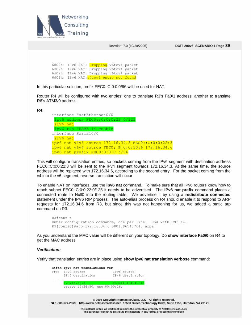
Revision: 7.0 (10/20/2005) DOiT-200v6- SCENARIO 1 Page 39
© 2005 Copyright NetMasterClass, LLC - All rights reserved.
1-888-677-2669 http://www.netmasterclass.net 13530 Dulles Technology Drive, Suite #150, Herndon, VA 20171
The material in this lab workbook remains the intellectual property of NetMasterClass., LLC The purchaser cannot re-distribute the materials in any format or resell this workbook
6d02h: IPv6 NAT: Dropping v6tov4 packet 6d02h: IPv6 NAT: Dropping v6tov4 packet 6d02h: IPv6 NAT: Dropping v6tov4 packet 6d02h: IPv6 NAT:v4tov6 entry not found
In this particular solution, prefix FEC0::C:0:0:0/96 will be used for NAT.
Router R4 will be configured with two entries: one to translate R3’s Fa0/1 address, another to translate R6’s ATM3/0 address: R4:
interface FastEthernet0/0 ipv6 address FEC0::C:0:0:22:4/125 ipv6 nat ipv6 rip FRAME-14 enable interface Serial0/0 ipv6 nat ipv6 nat v4v6 source 172.16.34.3 FEC0::C:0:0:22:3 ipv6 nat v6v4 source FEC0::B:0:0:10:6 172.16.34.6 ipv6 nat prefix FEC0:0:0:C::/96
This will configure translation entries, so packets coming from the IPv6 segment with destination address FEC0::C:0:0:22:3 will be sent to the IPv4 segment towards 172.16.34.3. At the same time, the source address will be replaced with 172.16.34.6, according to the second entry. For the packet coming from the v4 into the v6 segment, reverse translation will occur. To enable NAT on interfaces, use the ipv6 nat command. To make sure that all IPv6 routers know how to reach subnet FEC0::C:0:0:22:0/125 it needs to be advertised. The IPv6 nat prefix command places a connected route to Null0 into the routing table. We advertise it by using a redistribute connected statement under the IPV6 RIP process. The auto-alias process on R4 should enable it to respond to ARP requests for 172.16.34.6 from R3, but since this was not happening for us, we added a static arp command on R3.
R3#conf t Enter configuration commands, one per line. End with CNTL/Z. R3(config)#arp 172.16.34.6 0001.9654.7c40 arpa
As you understand the MAC value will be different on your topology. Do show interface Fa0/0 on R4 to get the MAC address Verification: Verify that translation entries are in place using show ipv6 nat translation verbose command:
R4#sh ipv6 nat translations ver Prot IPv4 source IPv6 source IPv4 destination IPv6 destination --- --- --- 172.16.34.3 FEC0::C:0:0:22:3 create 14:26:50, use 00:00:26,
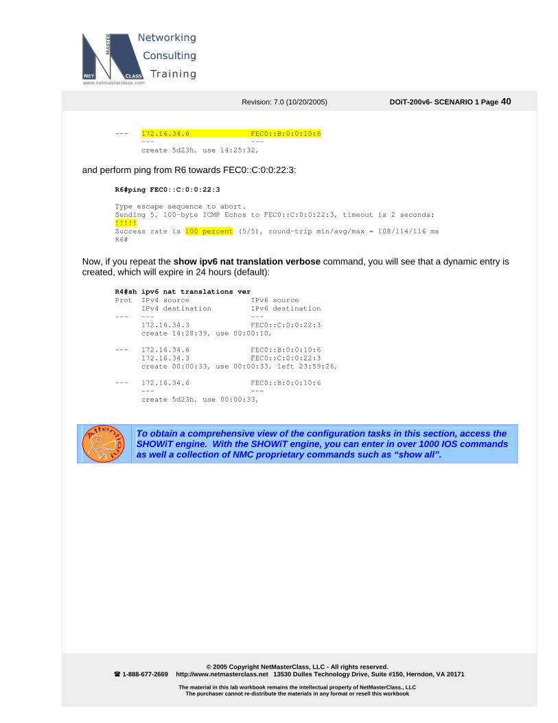
Revision: 7.0 (10/20/2005) DOiT-200v6- SCENARIO 1 Page 40
© 2005 Copyright NetMasterClass, LLC - All rights reserved.
1-888-677-2669 http://www.netmasterclass.net 13530 Dulles Technology Drive, Suite #150, Herndon, VA 20171
The material in this lab workbook remains the intellectual property of NetMasterClass., LLC The purchaser cannot re-distribute the materials in any format or resell this workbook
--- 172.16.34.6 FEC0::B:0:0:10:6 --- --- create 5d23h, use 14:25:32,
and perform ping from R6 towards FEC0::C:0:0:22:3:
R6#ping FEC0::C:0:0:22:3 Type escape sequence to abort. Sending 5, 100-byte ICMP Echos to FEC0::C:0:0:22:3, timeout is 2 seconds: !!!!! Success rate is 100 percent (5/5), round-trip min/avg/max = 108/114/116 ms R6#
Now, if you repeat the show ipv6 nat translation verbose command, you will see that a dynamic entry is created, which will expire in 24 hours (default):
R4#sh ipv6 nat translations ver Prot IPv4 source IPv6 source IPv4 destination IPv6 destination --- --- --- 172.16.34.3 FEC0::C:0:0:22:3 create 14:28:39, use 00:00:10, --- 172.16.34.6 FEC0::B:0:0:10:6 172.16.34.3 FEC0::C:0:0:22:3 create 00:00:33, use 00:00:33, left 23:59:26, --- 172.16.34.6 FEC0::B:0:0:10:6 --- --- create 5d23h, use 00:00:33,
To obtain a comprehensive view of the configuration tasks in this section, access the SHOWiT engine. With the SHOWiT engine, you can enter in over 1000 IOS commands as well a collection of NMC proprietary commands such as “show all”.
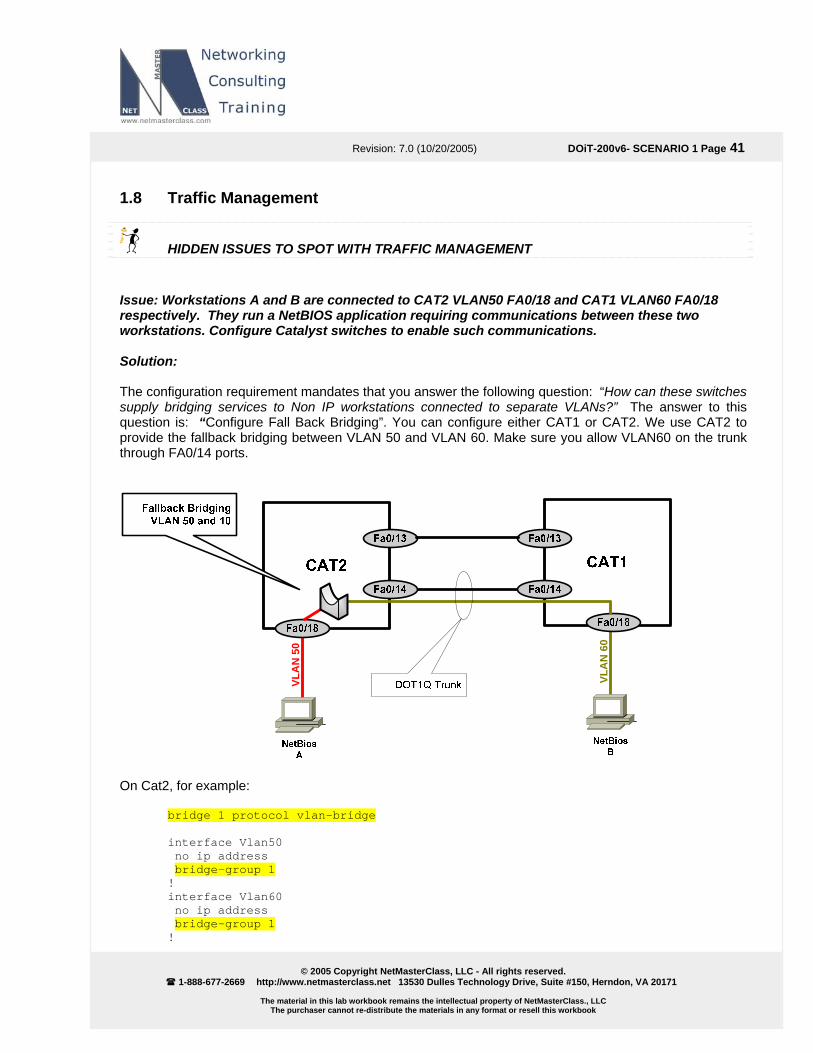
Revision: 7.0 (10/20/2005) DOiT-200v6- SCENARIO 1 Page 41
© 2005 Copyright NetMasterClass, LLC - All rights reserved.
1-888-677-2669 http://www.netmasterclass.net 13530 Dulles Technology Drive, Suite #150, Herndon, VA 20171
The material in this lab workbook remains the intellectual property of NetMasterClass., LLC The purchaser cannot re-distribute the materials in any format or resell this workbook
1.8 Traffic Management
HIDDEN ISSUES TO SPOT WITH TRAFFIC MANAGEMENT Issue: Workstations A and B are connected to CAT2 VLAN50 FA0/18 and CAT1 VLAN60 FA0/18 respectively. They run a NetBIOS application requiring communications between these two workstations. Configure Catalyst switches to enable such communications. Solution: The configuration requirement mandates that you answer the following question: “How can these switches supply bridging services to Non IP workstations connected to separate VLANs?” The answer to this question is: “Configure Fall Back Bridging”. You can configure either CAT1 or CAT2. We use CAT2 to provide the fallback bridging between VLAN 50 and VLAN 60. Make sure you allow VLAN60 on the trunk through FA0/14 ports.
VLA
N 5
0
VLA
N 6
0
On Cat2, for example:
bridge 1 protocol vlan-bridge interface Vlan50 no ip address bridge-group 1 ! interface Vlan60 no ip address bridge-group 1 !

Revision: 7.0 (10/20/2005) DOiT-200v6- SCENARIO 1 Page 42
© 2005 Copyright NetMasterClass, LLC - All rights reserved.
1-888-677-2669 http://www.netmasterclass.net 13530 Dulles Technology Drive, Suite #150, Herndon, VA 20171
The material in this lab workbook remains the intellectual property of NetMasterClass., LLC The purchaser cannot re-distribute the materials in any format or resell this workbook
CAT2#show spanning-tree 1 Bridge group 1 Spanning tree enabled protocol vlan-bridge Root ID Priority 32768 Address 000a.8afb.2680 This bridge is the root Hello Time 2 sec Max Age 30 sec Forward Delay 20 sec Bridge ID Priority 32768 Address 000a.8afb.2680 Hello Time 2 sec Max Age 30 sec Forward Delay 20 sec Aging Time 300 Interface Role Sts Cost Prio.Nbr Type ---------------- ---- --- --------- -------- -------------------------------- Vl50 Desg FWD 4 128.32 P2p Vl60 Desg FWD 4 128.33 P2p CAT2#
To obtain a comprehensive view of the configuration tasks in this section, access the SHOWiT engine. With the SHOWiT engine, you can enter in over 1000 IOS commands as well a collection of NMC proprietary commands such as “show all”.

Revision: 7.0 (10/20/2005) DOiT-200v6- SCENARIO 1 Page 43
© 2005 Copyright NetMasterClass, LLC - All rights reserved.
1-888-677-2669 http://www.netmasterclass.net 13530 Dulles Technology Drive, Suite #150, Herndon, VA 20171
The material in this lab workbook remains the intellectual property of NetMasterClass., LLC The purchaser cannot re-distribute the materials in any format or resell this workbook
1.9 Address Administration
HIDDEN ISSUES TO SPOT WITH ADDRESS ADMINISTRATION Issue: This is a basic DHCP server configuration task with one primary hidden issue: an unknown gateway address to configure with the DHCP pool… Use the gateway IP address most suitable for other tasks in this scenario Solution: Read ahead to the Gateway Redundancy Section. It will specify the default gateway address to use for VLAN 40 and ultimately with the DHCP server configuration on R3. Issue: Users on VLAN 40 “complain about not getting dhcp settings” The users are attached to a Catalyst 3550, and when the users power up their PC’s the Catalyst port becomes active and begins going through the standard states of the Spanning Tree Protocol: listening, learning and eventually to forwarding. It takes approximately 40 seconds to perform the transition through all standard Spanning Tree port states. While Spanning Tree is going through its standard port state transitions, DHCP requests are being generated by the workstations attached to the 3550 switch in an effort to obtain information from the DHCP server. If the requests are not serviced within a period of time, the DHCP requests timeout and the workstations cannot obtain their DHCP settings. Solution: Configure the Catalyst 3550 port command spanning-tree portfast to bypass the learning and listening states of Spanning Tree. Doing so will dramatically speed up the Catalyst port’s attainment of the Spanning Tree forwarding state. When the Spanning Tree forwarding state is attained, workstation DHCP requests can be successfully serviced without timing out. Portfast gets very aggressive with the forward-delay timer, but Spanning Tree is still running on these ports by default and will block looped ports. Issue: Make sure you exclude the already used IP addresses on VLAN 40 from the IP address pool used by the DHCP server. Solution: Enter the command ip dhcp excluded-address X.X.X.X for each address used by a router or switch interface already configured on VLAN 40.

Revision: 7.0 (10/20/2005) DOiT-200v6- SCENARIO 1 Page 44
© 2005 Copyright NetMasterClass, LLC - All rights reserved.
1-888-677-2669 http://www.netmasterclass.net 13530 Dulles Technology Drive, Suite #150, Herndon, VA 20171
The material in this lab workbook remains the intellectual property of NetMasterClass., LLC The purchaser cannot re-distribute the materials in any format or resell this workbook
Issue: Wireless workstations also obtain the IP address from this DHCP server. The administrator is concerned about IP address spoofing. Provide a solution allowing the DHCP server to explicitly know when a user logs out. Only authorized users should be able to respond to the ARP request Solution:
The new 12.3(4)T feature “DHCP Authorized ARP” documented at
http://www.cisco.com/univercd/cc/td/doc/product/software/ios123/123newft/123t/123t_4/gtautarp.htm#wp1027385 can help to solve this issue. Before the introduction of this feature, there was no mechanism to inform the DHCP server if a user had left the system ungracefully, which could result in excessive billing for a customer that had logged out but the system had not detected the log out. To prevent this problem, the DHCP Authorized ARP feature sends periodic ARP messages on a per-minute basis to determine if a user is still logged in. Only authorized users can respond to the ARP request. Unauthorized ARP responses are blocked at the DHCP server providing an extra level of security.
DHCP Authorized ARP disables dynamic ARP learning on an interface, therefore you need to configure the ARP static entry for R6’s IP address on R1 to recover the unicast reachability. Configuration and Verification: Here is the DHCP configuration on R1:
ip dhcp excluded-address 172.16.16.1 172.16.16.10 ! ip dhcp pool VLAN_40 network 172.16.16.0 255.255.255.0 domain-name xyz.com dns-server 172.16.16.10 default-router 172.16.16.254 update arp ! interface FastEthernet0/0 arp authorized ! arp 172.16.16.6 0007.ebaa.0e00 ARPA
The MAC address 0007.ebaa.0e00 is the MAC address of R6’s interface.
To obtain a comprehensive view of the configuration tasks in this section, access the SHOWiT engine. With the SHOWiT engine, you can enter in over 1000 IOS commands as well a collection of NMC proprietary commands such as “show all”.

Revision: 7.0 (10/20/2005) DOiT-200v6- SCENARIO 1 Page 45
© 2005 Copyright NetMasterClass, LLC - All rights reserved.
1-888-677-2669 http://www.netmasterclass.net 13530 Dulles Technology Drive, Suite #150, Herndon, VA 20171
The material in this lab workbook remains the intellectual property of NetMasterClass., LLC The purchaser cannot re-distribute the materials in any format or resell this workbook
1.10 Security
HIDDEN ISSUES TO SPOT WITH SECURITY CONFIGURATION Issue: Make R3 an http server. Solution: Configure ip http-server on R3. Issue: Configure an ACL on R1 to restrict http access from the serial interface of R2 during an explicitly specified range of time during every working week. Solution: Configure a time-based extended access-list on router R1. Test it by setting the clock to the restricted range of time and then telneting to R3 via port 80 from the serial interface of R2. Here is the definition of the time-range:
time-range R3-http-security periodic weekdays 8:00 to 16:59
Here is the access-list to restrict www to R1, referencing the time-range above. Note that www traffic is denied from the R2 serial address to each of the R1 interface addresses.
ip access-list extended R3-http-security deny tcp host 172.16.123.2 host 172.16.123.3 eq www time-range R3-http-security deny tcp host 172.16.123.2 host 172.16.103.1 eq www time-range R3-http-security deny tcp host 172.16.123.2 host 172.16.34.3 eq www time-range R3-http-security deny tcp host 172.16.123.2 host 172.16.35.3 eq www time-range R3-http-security permit ip any any !
Verification: It is recommended to enable debug ip icmp on router R2 to see “administratively prohibited” messages generated from R1 and sent to R2. When you see these messages, you know it is due to the configured time-based access-list. On R1 set the time to something later than 17:00 to activate the timed access list:
R1#clock set 15:00:00 4 Oct 2005 R1#
R1#sh clock 15:00:25.087 EDT Tue Oct 4 2005 R1#

Rubian
to
Rubian
to
DO
iT v
olum
e II
lab1
a
k
Revision: 7.0 (10/20/2005) DOiT-200v6- SCENARIO 1 Page 46
© 2005 Copyright NetMasterClass, LLC - All rights reserved.
1-888-677-2669 http://www.netmasterclass.net 13530 Dulles Technology Drive, Suite #150, Herndon, VA 20171
The material in this lab workbook remains the intellectual property of NetMasterClass., LLC The purchaser cannot re-distribute the materials in any format or resell this workbook
R1#sho access-lists Standard IP access list BGPtoOSPF 10 permit 6.6.6.0 (1 match) Extended IP access list R3-http 10 deny tcp host 172.16.123.2 host 172.16.123.3 eq www time-range R3-http-security (active) 20 deny tcp host 172.16.123.2 host 172.16.103.1 eq www time-range R3-http-security (active)
(8 matches) 30 deny tcp host 172.16.123.2 host 172.16.34.3 eq www time-range R3-http-security (active) 40 deny tcp host 172.16.123.2 host 172.16.35.3 eq www time-range R3-http-security (active) 50 permit ip any any (6009 matches) R1#
R2#telnet 172.16.103.1 80 Trying 172.16.103.1, 80 ... % Connection timed out; remote host not responding R2#
R1 denies the HTTP packets coming from R2. The time15:00 (3:00 PM) activates the timed access list and the access list denies the HTTP packets. Set the time which is outside of the scope of the time-range:
R1#clock set 20:00:00 4 Oct 2005 R1#
R2#telnet 172.16.103.1 80 Trying 172.16.103.1, 80 ... Open . HTTP/1.1 400 Bad Request Date: Tue, 04 Oct 2005 22:45:53 GMT Server: cisco-IOS Accept-Ranges: none 400 Bad Request [Connection to 172.16.103.1 closed by foreign host] R2#
As you see the HTTP is permitted by the R1 router.
To obtain a comprehensive view of the configuration tasks in this section, access the SHOWiT engine. With the SHOWiT engine, you can enter in over 1000 IOS commands as well a collection of NMC proprietary commands such as “show all”.

Revision: 7.0 (10/20/2005) DOiT-200v6- SCENARIO 1 Page 47
© 2005 Copyright NetMasterClass, LLC - All rights reserved.
1-888-677-2669 http://www.netmasterclass.net 13530 Dulles Technology Drive, Suite #150, Herndon, VA 20171
The material in this lab workbook remains the intellectual property of NetMasterClass., LLC The purchaser cannot re-distribute the materials in any format or resell this workbook
1.11 IOS Features
HIDDEN ISSUES TO SPOT WITH THE IOS FEATURES CONFIGURATION Issue: On router R4 create user “operator” with password “nmc”. In “show run” output password must be encrypted with MD5 hash. Make sure user “operator” goes directly to level 15 upon logon. Solution: Use username operator secret 0 nmc command to configure this user. Use username operator privilege 15 to bring user to level 15 upon login.
To obtain a comprehensive view of the configuration tasks in this section, access the SHOWiT engine. With the SHOWiT engine, you can enter in over 1000 IOS commands as well a collection of NMC proprietary commands such as “show all”.
1.12 QOS
HIDDEN ISSUES TO SPOT WITH THE QOS CONFIGURATION Issue: Configure Custom Queuing on the Serial interface of router R4 for four different categories of traffic so that each category receives a specific percentage of minimum bandwidth during periods of congestion. Each category of traffic possesses a different packet length. This Custom Queuing configuration task will require the configuration of three user-defined queues (out of a possible maximum of 16 queues) – one for the following three protocols: ftp, http and udp port 5001 as well as the configuration of the default custom-queue. This will require the configuration of the custom queuing “byte-count” command, which is the tool to use to adjust the allocation of bandwidth for a specific queue. Its default setting is 1500 bytes per queue. When you change the byte-count for a queue, you change the percentage of bandwidth allocated to that queue. Calculation of the correct byte-count requires that you take into account the packet size for each traffic type, as shown below. Solution: In order to find the correct byte-count to use in the queue-list, perform the following four-step series of calculations:
1. Determine the ratio of packet sizes for each queue category by dividing the largest packet size of all queue categories by each of the smaller packet sizes. In our scenario, the largest packet sizes are ftp and the default-queue

Revision: 7.0 (10/20/2005) DOiT-200v6- SCENARIO 1 Page 48
© 2005 Copyright NetMasterClass, LLC - All rights reserved.
1-888-677-2669 http://www.netmasterclass.net 13530 Dulles Technology Drive, Suite #150, Herndon, VA 20171
The material in this lab workbook remains the intellectual property of NetMasterClass., LLC The purchaser cannot re-distribute the materials in any format or resell this workbook
2. Multiply the results of Step One by the desired percentage for each queue.
3. Normalize the results of Step Two for each queue category and round up to the nearest whole
4. Multiply the normalized results of Step 3 by the number of bytes per packet. Provided below are
tep One: Determine the ratio of packet sizes
o do this, identify the class of traffic that possesses the largest packet size. In this case, it is FTP and the
TTP: 1500/600 = 2.5 /300 = 5
he ratio of FTP traffic to the “Other” traffic class is 1 since they both possess a packet size of 1500 bytes.
tep Two: Multiply the ratios of Step One with the desired bandwidth percentages
TP is allocated 20% of bandwidth. Therefore: 1 * .2 = 0.2 .75
2.0 0.1
tep Three: Normalize and Round Up to the Nearest Whole Number
o normalize FTP: 0.2/0.1 = 2 .5 round up to 8
tep Four: Multiply the results of Step Three by specific packet length
TP: 1500 * 2 = 3000
0 = 6000 00
he total number of bytes assigned to all byte counts equals 15,300 bytes. You can check your work by
TP: 3000/15300 = approximately 20% ely 40%
0%
number.
the calculation steps that need to be performed for this particular Exam.
S Tlast class of traffic that will be called “Other”. Both of these classes of traffic possess a packet size of 1500 bytes. Take the remaining traffic classes and divide 1500 bytes by their packet size: HUDP PORT 5001: 1500 T S FHTTP is allocated 30% of bandwidth. Therefore: 2.5 * .3 = 0UDP Port 5001 is allocated 40% of bandwidth. Therefore, 5 *.4 =All “OTHER” traffic is allocated 10% of bandwidth. Therefore, 1 * .1 = S TTo normalize HTTP: 0.75/0.1 = 7To normalize UDP Port 5001 traffic: 2.0/0.1 = 20 To normalize the “Other” traffic class: 0.1/0.1 = 1 S FHTTP: 600 * 8 = 4800 UDP Port 5001: 300 * 2Other Traffic Class: 1500 * 1 = 15 Tdividing each proposed queue byte-count by the total bytes found above, as shown: FHTTP: 4800/15300 = approximately 30%UDP Port 5001: 6000/15300 = approximat“Other” Traffic Class: 1500/15300 = approximately 1

Revision: 7.0 (10/20/2005) DOiT-200v6- SCENARIO 1 Page 49
© 2005 Copyright NetMasterClass, LLC - All rights reserved.
1-888-677-2669 http://www.netmasterclass.net 13530 Dulles Technology Drive, Suite #150, Herndon, VA 20171
The material in this lab workbook remains the intellectual property of NetMasterClass., LLC The purchaser cannot re-distribute the materials in any format or resell this workbook
Now that we have the proper byte-counts for each queue, we can construct and apply the queue-list. Queue 1 is associated with ftp control and data traffic and assigned a byte-count of 3000. Queue 2 is associated with http traffic and assigned a byte-count of 4800. Queue 3 is associated with traffic destined to UDP port 5001 and is assigned a byte-count of 6000. And queue 4 is designated the default queue and left with the default 1500-byte byte-count. Since there is a single PVC on R4 interface S0/0, it is not necessary to apply the queue-list to the DLCI using Frame-Relay traffic shaping, so it is simply applied to the physical interface with the command custom-queue-list 1.
queue-list 1 protocol ip 1 tcp ftp queue-list 1 protocol ip 1 tcp ftp-data queue-list 1 protocol ip 2 tcp www queue-list 1 protocol ip 3 udp 5001 queue-list 1 default 4 queue-list 1 queue 1 byte-count 3000 queue-list 1 queue 2 byte-count 4800 queue-list 1 queue 3 byte-count 6000
Verification: The command show queueing custom will verify the configuration. Use show queueing interface S0/0 to verify the queue-list has been properly applied.
R4#show queueing interface s0/0 Interface Serial0/0 queueing strategy: custom Output queue utilization (queue/count) 0/197938 1/2 2/0 3/0 4/54752 5/0 6/0 7/0 8/0 9/0 10/0 11/0 12/0 13/0 14/0 15/0 16/0 R4#
To obtain a comprehensive view of the configuration tasks in this section, access the SHOWiT engine. With the SHOWiT engine, you can enter in over 1000 IOS commands as well a collection of NMC proprietary commands such as “show all”.

Revision: 7.0 (10/20/2005) DOiT-200v6- SCENARIO 1 Page 50
© 2005 Copyright NetMasterClass, LLC - All rights reserved.
1-888-677-2669 http://www.netmasterclass.net 13530 Dulles Technology Drive, Suite #150, Herndon, VA 20171
The material in this lab workbook remains the intellectual property of NetMasterClass., LLC The purchaser cannot re-distribute the materials in any format or resell this workbook
1.13 Catalyst Specialties
HIDDEN ISSUES TO SPOT WITH THE CATALYST SPECIALTIES CONFIGURATION Issue: Change the MTU size on VLAN 3000 to twice the default. Solution: The default MTU size used on a Catalyst 3550 VLAN is 1500, so you need to adjust the MTU size to 3000 for VLAN 3000. Entering the vlan number in global configuration and in the “vlan config mode” entering the command mtu 3000 achieves the objective. Remember to do this on both Catalysts! Verification:
CAT1#sh vlan id 3000 VLAN Name Status Ports ---- -------------------------------- --------- ------------------------------- 3000 VLAN3000 active Fa0/8, Fa0/14 VLAN Type SAID MTU Parent RingNo BridgeNo Stp BrdgMode Trans1 Trans2 ---- ----- ---------- ----- ------ ------ -------- ---- -------- ------ ------ 3000 enet 103000 3000 - - - - - 0 0
Issue: Ports fa0/11 and fa0/12 of CAT1 need to allow devices that connect to them to join either VLAN 700 or 800. Precisely how these ports allow access to VLAN’s 700 and 800 is contained within a configuration file on a switch with the IP address of 172.16.200.1. Solution: You do not need to know precisely which of the two ports joins either VLAN 700 or 800. That depends upon the security clearance of an individual user. The language of both tasks imply that the ports will be DYNAMICALLY joining either VLAN 700 or 800 “depending on the security clearance of a user”. This language points towards configuring dynamic VLAN assignment using the command switchport access vlan dynamic on each port. The configuration file mentioned in task 1.15.3 is the VMPS Server configuration file that holds MAC address to VLAN associations. The Catalyst 3550, as a VMPS client, is configured with the address of a VMPS server switch with the command vmps server 172.16.200.1.
To obtain a comprehensive view of the configuration tasks in this section, access the SHOWiT engine. With the SHOWiT engine, you can enter in over 1000 IOS commands as well a collection of NMC proprietary commands such as “show all”.

Revision: 7.0 (10/20/2005) DOiT-200v6- SCENARIO 1 Page 51
© 2005 Copyright NetMasterClass, LLC - All rights reserved.
1-888-677-2669 http://www.netmasterclass.net 13530 Dulles Technology Drive, Suite #150, Herndon, VA 20171
The material in this lab workbook remains the intellectual property of NetMasterClass., LLC The purchaser cannot re-distribute the materials in any format or resell this workbook
1.14 Gateway Redundancy
HIDDEN ISSUES TO SPOT WITH THE GATEWAY REDUNDANCY CONFIGURATION Issue: Configure an HSRP standby group 3000 between R1 and R6. The HSRP group must be MD5 authenticated with the password “doitlab1” Solution:
HSRP version 1 supports only 255 groups, this scenario requires the higher number 3000. The HSRP version 2 is the solution. It was introduced as a new feature in 12.3(4)T , documented at http://www.cisco.com/univercd/cc/td/doc/product/software/ios123/123newft/123t/123t_4/gthsrpv2.htm#wp1027184 .
HSRP version 2 permits an expanded group number range, 0 to 4095. HSRP version 2 uses the new IP multicast address 224.0.0.102 to send hello packets instead of the multicast address of 224.0.0.2, which is used by version 1.
The MD5 authentication for HSRP was introduced in 12.3(2)T and documented at http://www.cisco.com/univercd/cc/td/doc/product/software/ios123/123newft/123t/123t_2/gthsrpau.htm
You can either configure MD5 key string or MD5 key chain. This scenario does not explicitly require the method. Key string approach was used in this answer key. Issue: Make R4 the primary HSRP gateway and R3 the backup for VLAN 30. Solution: Configure HSRP on routers R1 and R6 on VLAN 40. Assign R1 a higher HSRP priority value to make it preferred over R6. Issue: The HSRP logical address is 172.16.16.254. Solution: This address is important for completing the DHCP configuration sectionof this Exam. Here is the necessary configuration for interfaces f0/0 on R1 and f0/0.40 on R6: R1:
interface FastEthernet0/0 ip address 172.16.16.1 255.255.255.0 … standby version 2 standby 3000 ip 172.16.16.254

Revision: 7.0 (10/20/2005) DOiT-200v6- SCENARIO 1 Page 52
© 2005 Copyright NetMasterClass, LLC - All rights reserved.
1-888-677-2669 http://www.netmasterclass.net 13530 Dulles Technology Drive, Suite #150, Herndon, VA 20171
The material in this lab workbook remains the intellectual property of NetMasterClass., LLC The purchaser cannot re-distribute the materials in any format or resell this workbook
standby 3000 priority 110 standby 3000 preempt standby 3000 authentication md5 key-string doitlab1
R6:
interface FastEthernet0/0.40 encapsulation dot1Q 40 ip address 172.16.16.6 255.255.255.0 … standby version 2 standby 3000 ip 172.16.16.254 standby 3000 preempt standby 3000 authentication md5 key-string doitlab1
The standby group number, 3000, it must be used consistently in all of the HSRP standby commands on both routers. Note that the resulting virtual MAC address (0000.0c9f.fbb8) starts with the reserved portion (0000.0C9F.F000) and ends with bb8, which represent the standby group number 3000 in hexadecimal. The priority has been set to 110 so that it is higher than the default priority of 100 on R6, making R1 the Active router and R6 the Standby. The preempt keyword assures that R1 will be the active router as long as this interface is up. Verification:
R1#show standby FastEthernet0/0 - Group 3000 (version 2) State is Active 5 state changes, last state change 01:02:48 Virtual IP address is 172.16.16.254 Active virtual MAC address is 0000.0c9f.fbb8 Local virtual MAC address is 0000.0c9f.fbb8 (v2 default) Hello time 3 sec, hold time 10 sec Next hello sent in 0.128 secs Authentication MD5, key-string "doitlab1" Preemption enabled Active router is local Standby router is 172.16.16.6, priority 100 (expires in 7.648 sec) Priority 110 (configured 110) IP redundancy name is "hsrp-Fa0/0-3000" (default) R1#
To obtain a comprehensive view of the configuration tasks in this section, access the SHOWiT engine. With the SHOWiT engine, you can enter in over 1000 IOS commands as well a collection of NMC proprietary commands such as “show all”.

Revision: 7.0 (10/20/2005) DOiT-200v6- SCENARIO 1 Page 53
© 2005 Copyright NetMasterClass, LLC - All rights reserved.
1-888-677-2669 http://www.netmasterclass.net 13530 Dulles Technology Drive, Suite #150, Herndon, VA 20171
The material in this lab workbook remains the intellectual property of NetMasterClass., LLC The purchaser cannot re-distribute the materials in any format or resell this workbook
1.15 Multicast
HIDDEN ISSUES TO SPOT WITH THE MULTICAST CONFIGURATION Issue: Task 1.17.2 directs you to build a Shortest Path Tree involving a specified set of routers. Solution: Configure PIM Dense Mode. Since there is no mention of the construction of a shared tree, configuring Sparse Mode is not required. When you configure PIM Dense mode, you are limited to constructing source based multicast distribution trees or “shortest path trees”. When you configure PIM Spare Mode, you construct both shared multicast distribution trees and source based distribution trees. Issue: Make sure you receive replies from all routers listed for multicast pings generated by router R5. R1 will receive the multicast stream from R3 on S0/0 and from R4 on S0/0.14. R1 will examine its unicast routing table and determine that the RPF interface for the source address in the packets, 172.16.35.5, is interface S0/0. On that same basis, R1 will determine the upstream PIM neighbor to be R3. The traffic being received from R4 on interface S0/0.14 will be discarded, and a prune will be sent to R4. The problem with this is that receiver R2 out S0/0 will not receive the traffic. S0/0 is the RPF interface, and PIM Dense Mode never puts the RPF interface on the outgoing interface list. This situation is depicted in the drawing below.

Revision: 7.0 (10/20/2005) DOiT-200v6- SCENARIO 1 Page 54
© 2005 Copyright NetMasterClass, LLC - All rights reserved.
1-888-677-2669 http://www.netmasterclass.net 13530 Dulles Technology Drive, Suite #150, Herndon, VA 20171
The material in this lab workbook remains the intellectual property of NetMasterClass., LLC The purchaser cannot re-distribute the materials in any format or resell this workbook
Below you see the (S,G) entry on R1 for the multicast stream with source address 172.16.35.5 and destination 225.5.5.5. Notice that the incoming interface is Serial 0/0 and the RPF neighbor is R3. Because S0/0 is the RPF interface, that interface does not show up on the outgoing interface list. In other words, the multicast stream will not be sent back out the incoming interface.
(172.16.35.5, 225.5.5.5), 00:00:41/00:02:25, flags: LT Incoming interface: Serial0/0, RPF nbr 172.16.123.3 Outgoing interface list: Loopback101, Forward/Dense, 00:00:42/00:00:00 FastEthernet0/0, Forward/Dense, 00:01:39/00:00:00 Serial0/0.14, Prune/Dense, 00:00:42/00:02:20
Solution: The solution is to engineer the multicast stream so that it is allowed to come into S0/0.14 from R4. This will allow the stream to be sent out S0/0 toward R2. We do this by influencing the RPF check for this source. There are basically two ways to influence the RPF check; either change the unicast routing table or configure a static mroute entry. The latter method has fewer undesirable side effects than the former. Below you see the required static mroute command telling the router to make S0/0.14 the RPF interface for multicast traffic sourced from host address 172.16.35.5, and the resulting mroute table. Note the RPF interface is now S0/0.14, and S0/0 is receiving traffic.
ip mroute 172.16.35.5 255.255.255.255 Serial0/0.14 Also the PIM dense statement is not configured on the S0/0 interface of R3, to avoid the exchange of ASSERT messages between R1 and R3. R3’s distance and metric to the source of multicast stream is better, therefore R3 will win and R1 will lose and as a result will prune the S0/0 interface and block the multicast traffic to R2. If you debug this condition you will see the output on R1 similar to the following:
2d09h: PIM(0): Received v2 Assert on Serial0/0 from 172.16.123.3 2d09h: PIM(0): Assert metric to source 172.16.35.5 is [0/0] 2d09h: PIM(0): We lose, our metric [0/0] 2d09h: PIM(0): Prune Serial0/0/225.5.5.5 from (172.16.35.5/32, 225.5.5.5)
Here is the diagram showing the configuration strategy: Note the static mroute is use on R2 to change the RPF neighbor from R3 to R1. By default the next hop to 172.16.35.0/24 is R3 on the b NON_BROADCAST network:
R2#show ip route | inc 172.16.35.0 O E2 172.16.35.0/24 [110/20] via 172.16.123.3, 00:31:35, Serial0/0 R2#
This address is used in the mroute table for the RPF neighbor:
#sh ip mroute 225.5.5.5 IP Multicast Routing Table Flags: D - Dense, S - Sparse, B - Bidir Group, s - SSM Group, C - Connected, L - Local, P - Pruned, R - RP-bit set, F - Register flag, T - SPT-bit set, J - Join SPT, M - MSDP created entry, X - Proxy Join Timer Running, A - Candidate for MSDP Advertisement, U - URD, I - Received Source Specific Host Report, Z - Multicast Tunnel, z - MDT-data group sender,

Revision: 7.0 (10/20/2005) DOiT-200v6- SCENARIO 1 Page 55
© 2005 Copyright NetMasterClass, LLC - All rights reserved.
1-888-677-2669 http://www.netmasterclass.net 13530 Dulles Technology Drive, Suite #150, Herndon, VA 20171
The material in this lab workbook remains the intellectual property of NetMasterClass., LLC The purchaser cannot re-distribute the materials in any format or resell this workbook
Y - Joined MDT-data group, y - Sending to MDT-data group Outgoing interface flags: H - Hardware switched, A - Assert winner Timers: Uptime/Expires Interface state: Interface, Next-Hop or VCD, State/Mode (*, 225.5.5.5), 00:01:08/stopped, RP 0.0.0.0, flags: DCL Incoming interface: Null, RPF nbr 0.0.0.0 Outgoing interface list: Loopback102, Forward/Dense, 00:01:08/00:00:00 Serial0/0, Forward/Dense, 00:01:08/00:00:00 (172.16.35.5, 225.5.5.5), 00:00:39/00:02:22, flags: LT Incoming interface: Serial0/0, RPF nbr 172.16.123.3 Outgoing interface list: Loopback102, Forward/Dense, 00:00:41/00:00:00 R2#
And because the traffic is coming from the 172.16.123.1 we need to change the RPF neighbor to 172.16.123.1 on R2 by using static mroute command:
ip mroute 172.16.35.5 255.255.255.255 172.16.123.1
ping 225.5.5.5
(172.16.35.5, 225.5.5.5), 00:01:32/00:01:27, flags: L Please check the SHOWiT engine for the configuration details. Use the following commands:
o show run o show all run o show ip pim neighbor o show ip mroute
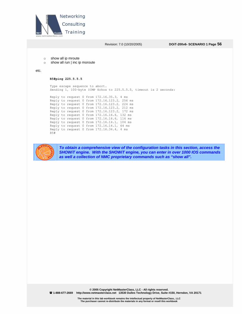
Revision: 7.0 (10/20/2005) DOiT-200v6- SCENARIO 1 Page 56
© 2005 Copyright NetMasterClass, LLC - All rights reserved.
1-888-677-2669 http://www.netmasterclass.net 13530 Dulles Technology Drive, Suite #150, Herndon, VA 20171
The material in this lab workbook remains the intellectual property of NetMasterClass., LLC The purchaser cannot re-distribute the materials in any format or resell this workbook
o show all ip mroute o show all run | inc ip moroute
etc.
R5#ping 225.5.5.5 Type escape sequence to abort. Sending 1, 100-byte ICMP Echos to 225.5.5.5, timeout is 2 seconds: Reply to request 0 from 172.16.35.3, 4 ms Reply to request 0 from 172.16.123.2, 256 ms Reply to request 0 from 172.16.123.2, 224 ms Reply to request 0 from 172.16.123.2, 212 ms Reply to request 0 from 172.16.123.2, 172 ms Reply to request 0 from 172.16.16.6, 132 ms Reply to request 0 from 172.16.16.6, 116 ms Reply to request 0 from 172.16.14.1, 104 ms Reply to request 0 from 172.16.14.1, 64 ms Reply to request 0 from 172.16.34.4, 4 ms R5#
To obtain a comprehensive view of the configuration tasks in this section, access the SHOWiT engine. With the SHOWiT engine, you can enter in over 1000 IOS commands as well a collection of NMC proprietary commands such as “show all”.
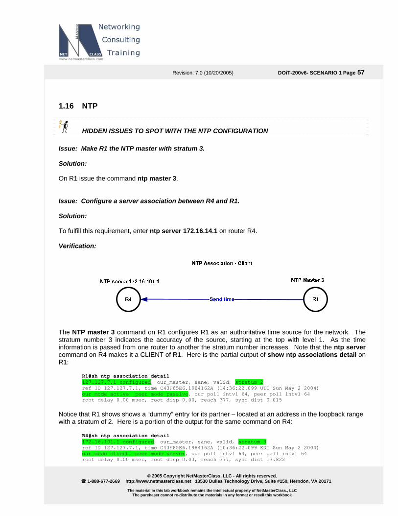
Revision: 7.0 (10/20/2005) DOiT-200v6- SCENARIO 1 Page 57
© 2005 Copyright NetMasterClass, LLC - All rights reserved.
1-888-677-2669 http://www.netmasterclass.net 13530 Dulles Technology Drive, Suite #150, Herndon, VA 20171
The material in this lab workbook remains the intellectual property of NetMasterClass., LLC The purchaser cannot re-distribute the materials in any format or resell this workbook
1.16 NTP
HIDDEN ISSUES TO SPOT WITH THE NTP CONFIGURATION Issue: Make R1 the NTP master with stratum 3. Solution: On R1 issue the command ntp master 3. Issue: Configure a server association between R4 and R1. Solution: To fulfill this requirement, enter ntp server 172.16.14.1 on router R4. Verification:
The NTP master 3 command on R1 configures R1 as an authoritative time source for the network. The stratum number 3 indicates the accuracy of the source, starting at the top with level 1. As the time information is passed from one router to another the stratum number increases. Note that the ntp server command on R4 makes it a CLIENT of R1. Here is the partial output of show ntp associations detail on R1:
R1#sh ntp association detail 127.127.7.1 configured, our_master, sane, valid, stratum 2 ref ID 127.127.7.1, time C43F85E6.1984162A (14:36:22.099 UTC Sun May 2 2004) our mode active, peer mode passive, our poll intvl 64, peer poll intvl 64 root delay 0.00 msec, root disp 0.00, reach 377, sync dist 0.015
Notice that R1 shows shows a “dummy” entry for its partner – located at an address in the loopback range with a stratum of 2. Here is a portion of the output for the same command on R4:
R4#sh ntp association detail 172.16.101.1 configured, our_master, sane, valid, stratum 3 ref ID 127.127.7.1, time C43F85E6.1984162A (10:36:22.099 EDT Sun May 2 2004) our mode client, peer mode server, our poll intvl 64, peer poll intvl 64 root delay 0.00 msec, root disp 0.03, reach 377, sync dist 17.822

Revision: 7.0 (10/20/2005) DOiT-200v6- SCENARIO 1 Page 58
© 2005 Copyright NetMasterClass, LLC - All rights reserved.
1-888-677-2669 http://www.netmasterclass.net 13530 Dulles Technology Drive, Suite #150, Herndon, VA 20171
The material in this lab workbook remains the intellectual property of NetMasterClass., LLC The purchaser cannot re-distribute the materials in any format or resell this workbook
R4 is an ntp client. A host operating in this mode sends periodic messages regardless of the reachability state or stratum of its peer. By operating in this mode the host, usually a LAN workstation, announces its willingness to be synchronized by, but not to synchronize the peer. R4 sees its peer, R1, as an ntp server. This type of association is ordinarily created upon arrival of a client request message and exists only in order to reply to that request, after which the association is dissolved. By operating in this mode the host, usually a LAN time server, announces its willingness to synchronize, but not to be synchronized by the peer. Issue: Configure a peer association between R3 and R4. Solution: In order to fulfill this requirement, issue the command ntp peer 172.16.104.1 on R3, or you can issue the command ntp peer 172.16.103.1 on R4. The peer command can be entered on either side of the association, because Cisco routers are in NTP symmetric passive mode by default. Verification:
Here is a portion of the association detail as seen on R3:
R3#show ntp association detail 172.16.104.1 configured, our_master, sane, valid, stratum 4 ref ID 172.16.101.1, time C43F85F9.C34B636B (14:36:41.762 UTC Sun May 2 2004) our mode active, peer mode passive, our poll intvl 64, peer poll intvl 64 root delay 30.56 msec, root disp 6.48, reach 377, sync dist 50.461
You see that the stratum has increased to 4. Also note that R3 is seen as mode passive for this association, whereas it is in client mode in its association with R1. When you configure the explicit “ntp peer” command on a Cisco router (ntp peer X.X.X.X), the router is configured in “symmetric active” mode. When you allow a Cisco router to act as an NTP peer without any explicit NTP configuration statement on it (i.e., the router is maintaining its default status as an ntp peer), the router is actually configured in “symmetric passive” mode. Symmetric Active (1): A host operating in this mode sends periodic messages regardless of the reachability state or stratum of its peer. By operating in this mode the host announces its willingness to synchronize and be synchronized by the peer. Symmetric Passive (2): This type of association is ordinarily created upon arrival of a message from a peer operating in the symmetric active mode and persists only as long as the peer is reachable and operating at a stratum level less than or equal to the host; otherwise, the association is dissolved.

Revision: 7.0 (10/20/2005) DOiT-200v6- SCENARIO 1 Page 59
© 2005 Copyright NetMasterClass, LLC - All rights reserved.
1-888-677-2669 http://www.netmasterclass.net 13530 Dulles Technology Drive, Suite #150, Herndon, VA 20171
The material in this lab workbook remains the intellectual property of NetMasterClass., LLC The purchaser cannot re-distribute the materials in any format or resell this workbook
However, the association will always persist until at least one message has been sent in reply. By operating in this mode the host announces its willingness to synchronize and be synchronized by the peer. You should know the difference between them because it is a very common source for NTP peer associations to go into an “invalid” and “insane” state. If you configure an ntp peer statement on R3 pointing to R4 and on R4 pointing to R3, then after a few minutes, you will see that R4 has marked its peer association with R3 as “insane” and “invalid”. This is because both routers are operating in the NTP “symmetric active” mode.
R4#show ntp association detail 172.16.103.1 configured, insane, invalid, stratum 5 ref ID 172.16.104.1, time C43F96F7.79CFCCA8 (11:49:11.475 EDT Sun May 2 2004) our mode active, peer mode passive, our poll intvl 1024, peer poll intvl 128 root delay 83.42 msec, root disp 2.17, reach 376, sync dist 76.523
To obtain a comprehensive view of the configuration tasks in this section, access the SHOWiT engine. With the SHOWiT engine, you can enter in over 1000 IOS commands as well a collection of NMC proprietary commands such as “show all”.