DOE/METC/C-96/7203 Filter System Cost Comparison for …/67531/metadc669785/... · ·...
18
DOE/METC/C-96/7203 Filter System Cost Comparison for IGCC and PFBC Power Systems Authors: Richard A. Dennis (METC) Heather M. McDaniel (METC) Thomas Buchanan (GilberKommonwealth) Herbert Chen (GilberKommonwealth) Lora Beth Harbaugh (Gilbert/Commonwealth) Michael Klett (GilbertlCommonwealth) Roman Zaharchuk (GilberKommonwealth) Conference Title: 12th Annual International Pittsburgh Coal Conference Conference Location: Pittsburgh, Pennsylvania Conference Dates: September 11-15, 1995 Conference Sponsor: University of Pittsburgh DISTRIBUTION OF THJS DOCUMENT IS UNLIMITED M
Transcript of DOE/METC/C-96/7203 Filter System Cost Comparison for …/67531/metadc669785/... · ·...
DOE/METC/C-96/7203
Filter System Cost Comparison for IGCC and PFBC Power Systems
Authors: Richard A. Dennis (METC) Heather M. McDaniel (METC) Thomas Buchanan (GilberKommonwealth) Herbert Chen (GilberKommonwealth) Lora Beth Harbaugh (Gilbert/Commonwealth) Michael Klett (GilbertlCommonwealth) Roman Zaharchuk (GilberKommonwealth)
Conference Title: 12th Annual International Pittsburgh Coal Conference
Conference Location: Pittsburgh, Pennsylvania
Conference Dates: September 11-15, 1995
Conference Sponsor: University of Pittsburgh
DISTRIBUTION OF THJS DOCUMENT IS UNLIMITED M

DISCLAIMER
This report was prepared as an account of work sponsored by an agency of the United States Government. Neither the United States Government nor any agency thereof, nor any of their employees, makes any warranty, express or implied, or assumes any legal liability or responsibility for the accuracy, completeness, or usefulness of any information, apparatus, product, or process disclosed, or represents that its use would not infringe privately owned rights. Reference herein to any specific commercial product, process, or service by trade name, trademark, manufacturer, or otherwise does not necessarily constitute or imply its endorsement, recommendation, or favoring by the United States Government or any agency thereof. The views and opinions of authors expressed herein do not necessarily state or reflect those of the United States Government or any agency thereof.
This report has been reproduced directly from the best available copy.
Available to DOE and DOE contractors from the Office of Scientific and Technical Information, 175 Oak Ridge Turnpike, Oak Ridge, TN 37831; prices available at (615) 576-8401.
Available to the public from the National Technical Information Service, U.S. Department of Commerce, 5285 Port Royal Road, Springfield, VA 22161; phone orders accepted at (703) 487-4650.

Filter System Cost Comparison For IGCC and PFBC Power Systems
Richard A. Dennis Heather M. McDaniel
Power Systems Technology Division Morgantown Energy Technology Center United States Department of Energy
Morgantown, WV
Thomas Buchanan Herbert Chen
Lora Beth Harbaugh Michael Klett Roman Zaharchuk
Gilbert/Commonwealth Engineers and Consultants Reading, Pennsylvania
ABSTRACT
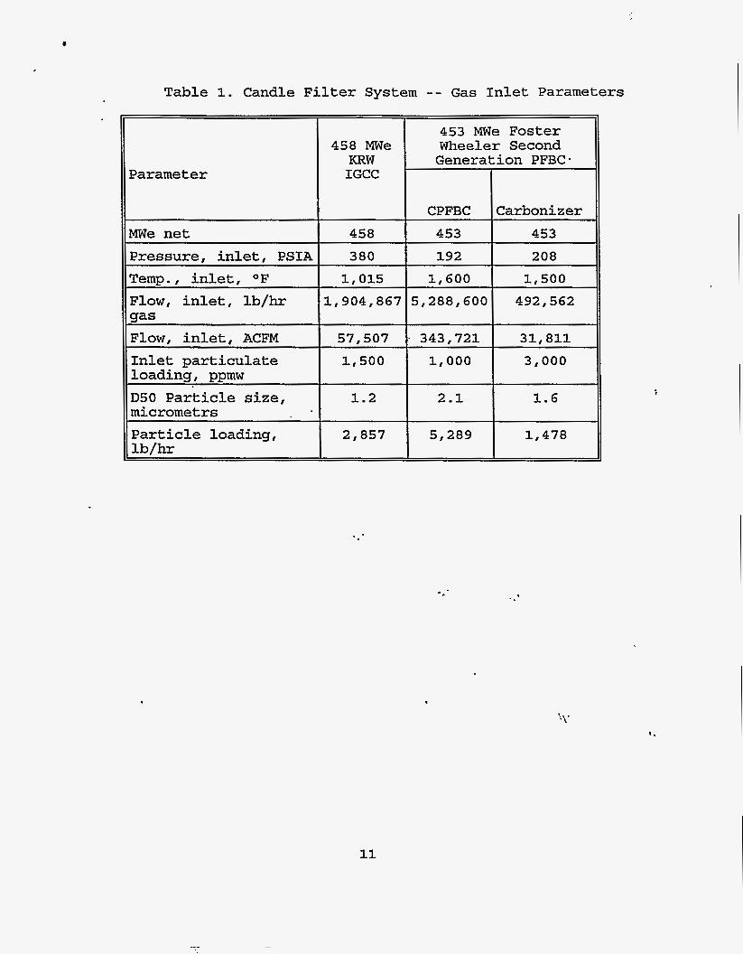
A cost comparison was conducted between the filter systems for two advanced coal-based power plants. The results from this study are presented. The filter system is based on a Westinghouse advanced particulate filter concept, which is designed to operate with ceramic candle filters. The Foster Wheeler second-generation 453 MWe (net) pressurized fluidized-bed combustor (PFBC) and the KRW 458 MWe (net) integrated gasification combined cycle (IGCC) power plants are used for the comparison. presents the general differences of the two power plants and the process-related filtration conditions for PFBC and 'IGCC systems. The results present the conceptual designs- for the*PFBC and IGCC filter systems as well as a cost summary comparison. summary comparison includes the total plant cost, the fixed operating and maintenance cost, the variable operating and maintenance cost, and the effect on the cost of electricity (C0E)for the two filter systems.
The comparison
The cost
1'1' INTRODUCTION
Integrated gasification combined cycle (IGCC) and pressurized fluidized-bed combustion (PFBC) power systems have made it possible to use coal while still protecting the environment. Such power systems significantly reduce the pollutants associated with coal-fired plants built before the 1970s. This environmental performance is possible, in part,
superior . because chemical
I'
1

and particulate gas stream cleanup is conducted at high- temperature and high-pressure process conditions.
Both the IGCC and PFBC power systems require particulate cleanup systems.. inherent differences in the coal conversion process and the volume of process gas that must be filtered. To assess the cost of PFBC and IGCC systems the cost of the respective filter systems must be assessed. .This paper presents filter system costs for both applications and compares these costs to the total power plant cost. plants are compared as well as the process-related filtration conditions for PFBC and IGCC systems. Conceptual designs for the PFBC and IGCC filter systems are presented as well as a cost summary comparison. This comparison includes the total plant cost, the fixed operating and maintenance cost, the variable operating and maintenance cost, and the effect on the cost of electricity for the two filter systems.
Although they are sized differently because of the
The general differences of the two power
As a basis for the cost comparison a Westinghouse Science & Technology Center advanced particulate filter (APF) design is used. We present a discussion of the conceptual design and design ’ differences for two different applications.
ADVANCED POWER SYSTEMS
To provide a basis for an economic comparison of IGCC and PFBC filter systems, a nominal 450 MWe power plant size was selected. The KRW air-blown gasifier represents the IGCC system and the Foster Wheeler (FW) Second-Generation PFBC represents the combustion system. A brief description of these power plants is presented below. outputs relevant to the conceptual design of the filter system.
Included in this description are the process
.. KRW Intesrated Gasification Combined Cvcle Power System
A nominal 458 MWe net power output KRW air-blown gasifier was selected for the IGCC base case.[lI Air, steam, sorbent and coal are processed through a fluidized bed reactor to produce a low- Btu fuel gas. in-bed sorbent. cyclones prior to entering the filter system. filter, additional desulfurization is performed after which the gas enters a combustor and turbine system for power generation. Table 1 presents the process conditions as the KRW fuel gas enters the filter.
The fuel gas is partially desulfurized from the This fuel gas is cooled and pqe-cleaned with
Downstryam of the \ *
2

Foster Wheeler Second-Generation Pressurized Fluidized Bed Combustor Power System
A nominal 453-MWe net power output Foster Wheeler second- generation PFBC is selected for PFBC base case.C21 Coal mixed with sorbent is pyrolized in a pressurized air-blown’ fluidized bed carbonizer to produce a low-Btu fuel gas and char. and partially utilized sorbent are sent to a circulating fluidized-bed combustor. Combustion air, additional sorbent, and possibly more coal are added to the combustor to generate a high- temperature oxygen-rich flue gas. The second-generation PFBC system requires two filter systems. Flue gas from the combustor is precleaned in a cyclone and fed to the combustion filter system. Fuel gas from the carbonizer flows through a precleaning cyclone before entering a separate filter system. particulate-free fuel gas from the carbonizer and the oxygen-rich combustion exhaust are then mixed and combusted to drive a gas turbine. Table 1 presents the process gas conditions entering the filter vessels.
The char
The
FILTER SYSTEM DESCRIPTION
The Westinghouse advanced particulate filter (APF) was selected as the basis for the economic comparison.C31 APF has cluster modules that support plenums or arrays of candle filters. For both power plants being considered, the conceptual design of the filter system will include four clusters, with each cluster supporting four plenums. candle filters. Each cluster is individually supported from an uncooled high alloy tubesheet. tubesheet is accommodated through an expansion cone which connects it to the inner wall of the filter vessel. Each cluster is attached to the tube sheet with a split ring assembly, which facilitates dismantling and maintenance of the cluster assembly. During thermal expansion, the clusters are- free to*grow down. Figure 1 shows the basic filter-system concept for the two power systems.
The Westinghouse
Each plenum holds up to 74
Thermal expansion of the
This filter design is very similar to the design used for the Tidd 70-MWe PFBC one-seventh-flow slip-stream testing.[41 Tidd APF design, three clusters with three plenums each were housed in a single pressure vessel, with up to 56 filters per
In this design, dirty gas passes through the candle filters; dust” is deposited on the candle filters, forming a cake-like structure. Cleaned gas is conveyed through the inside diameter of the candle filter and is commingled in a common plenum. The cleaned gas is then conveyed through a dedicated pipe to the clean side of the tubesheet. Once above the tubesheet, the
In the
YL * ’ plenum.
r-
3

cleaned process gas exits through a nozzle in the pressure vessel head.
The on-line filter cleaning system is similar to the one used in the Tidd filter facility, and consists of a compressor, air dryer, primary accumulator tank, air filter, and several second- ary accumulator tanks with 2-inch fastiacting baek-pulse valves. When the back-pulse valves are activated during candle filter blowback, a short duration pulse of cleaning fluid is blown through piping into the candle filter plenum and then into the candle filters.
In our evaluation, we have the pulse blown into a plenum that contains up to 74.candles. The blowback gas for PFBC is com- pressed air. The blowback gas for the gasifier and carbonizer is fuel gas taken from the clean gas stream and then cooled and compressed.
At the filter, a pressure differential of only a few psig is needed to blow off the filter cake. Because of the very high pressure drop from the tank to the individual candle filters, high tank pressures are required. At Tidd, the tank and compressor are rated for 1,500 psig. Normally, the back-pulse pressure has been 800 psig, but up to 1,200 psig has been needed at times. will be used in the design.
For this evaluation, a 400 OF maximum blowback gas
Operational conditions for the filter systems were developed by Gilbert/Commonwealth using a first-principle based spread-sheet model. [51
. .- Filter System For the Foster Wheeler Second Generation PFBC
For the 453 MWe power plant, ten candle filter vessels were required using a 10 feet per minute (fpm)'-€ilter-face velocity. This is a reasonable face velocity assuming a cake-specific resistance of 15.6 (in.w)/(fpm)/(lb/ft2). The dust loading to the filter is 1,000 ppmw, since cyclones precede the filter vessels.
The reservoir blowback pressure required to remove the dust cake from the filter eyery 60 minutes is 729 psi. pressure is sensitive to the hardware between the reseyoir and the candle filter. Table 2 summarizes the-candle filter vessel design. process conditions. Figure 2 shows the piping arrangement and Table 4 presents the piping specifications. Compressed air at 400 OF is supplied to the reservoir by a reciprocating compressor with intercoolers.
The blowback
Table 3 summarizes the blowback system design and t .
The brake horsepower required for the
4
.
compressor is 167 Hp. the plenum, the Atkomatic valve is opened and the candles are blown back with 10.2 lb of air in a timeframe of 700 milliseconds. re-attachment, the candles are blown back one cluster at a time, starting with the top plenum and moving down in sequence until the 16 plenums in the vessel are cleaned. The total amount of blowback air is 1,631 lb/hr. when compared to the total flue gas flow of 5,288,600 lb/hr; therefore, the dilution effect can be ignored.
When the trigger pressure is reached in
In order to lessen the amount of particulate -
This is an insignificant amount
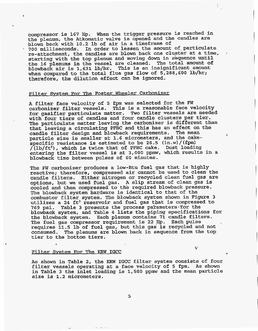
Filter Svstem For The Foster Wheeler Carbonizer
A filter face velocity of 5 fpm was selected for the FW carbonizer filter vessels. for gasifier particulate matter. Two filter vessels are needed with four tiers of candles and four candle clusters per tier. The particulate matter 1eaving.the carbonizer is different than that 1eaving.a circulating PFBC and this has an effect on the candle filter design and blowback requirements. particle size is smaller at 1.6 micrometers, and the cake- specific resistance is estimated to be 28.5 (in.w)/(fpm) /(lb/ft*), which is twice that of PFBC cake. Dust loading entering the filter vessel is at 3,000 ppmw, which results in a blowback time between pulses of 60 minutes.
This is a reasonable face velocity
The mean
The FW carbonizer produces a low-Btu fuel gas that is highly reactive; therefore, compressed air cannot be used to clean the candle filters. Either nitrogen or recycled clean fuel gas are options, but we used fuel gas. A slip stream of clean gas is cooled and then compressed to the required blowback pressure. The blowback system hardware is identical to that of the combustor filter system. The blowback system shown in Figure 3 utilizes a 24 ft3 reservoir and fuel gas that is compressed to 769 psi. blowback system, and Table 4 lists the piping specifications for the blowback system. The fuel gas compressor requirement is 22 .Hp. requ.ires 11.5 lb of fuel gas, but this gas is recycled and not consumed. The plenums are blown back in sequence from the top tier to the bottom tiers.
Filter Svstem For The KRW IGCC
Table 3 presents the process paEameters.sTor the
Each plenum contains 71 candle filters. Each pulse
\ir' I.
As shown in Table 2, the KFtW IGCC filter system consists of four filter vessels operating at a face velocity of 5 fpm. in Table 3 the inlet loading is 1,500 ppmw and the mean particle size is 1.2 micrometers.
As shown
5

When using the Gilbert/Commonwealth spreadsheet [51 to determine the operating conditions of the blowback system the cake-specific resistance is an important parameter. In the PFBC, this resistance is 15.6 (in.w) / (fpm) / (lb/ft2) which is considered
. reasonable. The carbonizer cake is double this, at 28.5 (in,w) / (fpm) / (lb/ft2) . For the gasifier, howevel, the specific resistance has been reported as high as ten times that of PFBC. A choice of 43 .9 (in.w) / (fpm) / (lb/ft2), three times that of CPFBC, was made for the gasifier. This has resulted in the highest blowback pressure at 1,094 psi, and the shortest time between pulses at 40 minutes. Fifteen pounds of fuel gas are used per pulse.
Clean fuel gas is cooled, then compressed and stored in the blowback reservoir until needed. The reservoir size is 55 ft3, double that of the CPEBC reservoir to keep the reservoir pressure below 1,000 psig. Table 3 presents process parameters for the blowback system: Each plenum holds 62 candle filters. The fuel gas compressor requirement is 94 Hp, relatively high because of the pulse pressure and quantity needed for blowback. Figure 4 shows the piping arrangement and Table 4 lists piping specifications.
ECONOMIC ANALYSIS
The economics of ceramic barrier filter systems were developed by consistently defining the capital and operating costs, and then performing an economic analysis based on the incremental cost of electricity (COE) as the figure of merit. The conceptual cost estimate was determined on the basis of system scope, equipment quotes, the CPFBC and the IGCC rkference plants, and Gilbert/Commonwealth in-house cost data.[5]
Table 5 shows the total plant cost (TPC) and the component COE costs for each case. as well as particle loading determine the number of vessels required for each system. As shown in Table 5, the COE of the systems with similar applications are equivalent. Wheeler CPFBC and carbonizer have the same working pressure so the TPC is equivalent on a cost-per-vessel level. filter system has a higher working pressure, and more expensive vessels and thus has a higher TPC on a per-vessel basis,
We emphasized obtaining good cost results at the TPC leGel for the two systems. To highlight the cost of the filter systems, the battery limits of the estimate are from the inlet piping of the filter vessels to the inlet of the ash coolers. Costs include equipment, materials, labor, indirect construction costs, engineering, and contingencies. Table 6 lists TPC components.
The face velocities'*for these applications
The Foster
The IGCC
, ,
6

Operation and maintenance ( O m ) cost values were determined on a first-year basis and subsequently levelized over the 30-year plant life. Consumable were evaluated on the basis of the quantity required; operation cost was determined on the basis of the number of operators; basis of maintenance costs i-equired for each major plant section. These operating costs were then converted to unit values of $/kW-yr or mills/kWh.
and maintenance was evaluated on the
The capital and operating costs of the plant are combined with plant performance in the comprehensive evaluation of COE.
In summary, the following economic assumptions were made:
o Plant book life is 30 years o Capacity factor is 65 percent o Plant in-service date is January 1995 o COE determined on a levelized, current dollar basis o COE methodology was based on EPRI TAG methodology
CONCLUSIONS
The cost driver of the total system cost are the vessel costs. The vessel costs represent approximately 75 percent of the total plant cost. The blowback systems, including gas compression, only represent a small percentage of the total system cost.
The cost of the ceramic barrier filter system for the advanced PFBC plant is about 2.5 times that for the IGCC plant. The PFBC plant requires two filter systems, one for the combustor and one for the carbonizer, and has a mtrch higher gas volume. of the cleanup system as compared to the total plant cost, however, is relatively small: PFBC and 4 to 5 percent for the IGCC.
The cost
10 to 12 percent for the advanced ..
7
\

REFERENCES
1.
2.
3.
4.
5.
The M.W. Kellogg Company , Assessment of Coal Gas i f i ca t ion /Hot Gas Cleanup Based Advanced Gas Turbine Systems, Final Report , for the U.S. Department of Energy . Under Contract No. DE-FC21-89MC26019, December 1990
Foster Wheeler Development Corporation, Second-Generation Pressur i zed F l u i d i z e d Bed Combustion Plant Conceptual Design and Opt imi za t ion o f a Second-Generation PFB Combustion P l a n t , Phase 1, Task 1; Topical Report, for the U.S. Department of Energy Under Contract No. DE-AC21-86MC21023, September 1989
Lippert, T.E., G.J. Bruck, R.A. Newby, E.E. Smetzer, Specific Filter Designs For PFBC, Proceedings o f the Coal- Fired Power Systems 93 -- Advances i n IGCC and PFBC Review Meet ing, 1993, D.L. Bonk Editor
Mudd, M.J. and J.D. Hoffman, Tidd Hot Gas Cleanup .Program, Final Report, Contract DE-FC21-89MC26042, for the U.S. Department of Energy by American Electric Power Service Corporation, Columbus, Ohio. (In. Press)
Gilbert/Commonwealth, Inc. Assessment and Evaluat ion o f Ceramic F i l t e r Cleaning Techniques, Topical Report , for the U.S. Department of Energy, Contract No. DE-AC21-89MC25177, October 1994
. .*
. .-
8

, Filter System
T - - AshDischarge
Candle h Y
A CleanGas
I
Dust Seal
o w GaS
I
Candle Mount and Seal
.,
Figure 1. Westinghouse Advanced Particulate Filter
Ejector
per PI-
Compressor Receiver CPFBCCandla
100 cu. ft. NterVossel
10 Vessels
-.
,'\ '
Figure 2. Blowback System For the Foster Wheeler Circulating PFBC
9
..-

2 I l l - To Reservoir2 To Reservoir 3 To Reservolr 4
)To Reservoir 3 +To Reservolr 4
Figure 3. Blowback System For the Foster Wheeler Carbonizer
.. - , .
-r>a ... ..
To Reservoir 2 TO Reservoir 3 To Reservoir 4
I/'"""
- 2 5 0 x 5 0 '
c
Fuel Gks Fuel Gas Compressor Receiver
Fuel Gas Cooler
Figure 4. Blowback System For the KRW IGCC
10
CPFBC
453
192
1,600
Table 1. Candle Filter System - - Gas Inlet Parameters
Carbonizer 453
208
1,500
Parameter
MWe net
458 MWe KRW IGCC
458
Pressure, inlet, PSIA
Temp., inlet, OF Flow, inlet, lb/hr gas Flow , inlet, ACFM Inlet particulate loading, ppmw
micrometrs
Particle loading, lb/hr
D50 Particle size,
380
1,015
1,904,867
57 , 507 1,500
1.2
2,857
31,811
1,000 I 3,000
1,478
11

Table 2. Candle Filter Vessel Design
Ir ET7 Second KRW IGCC
Gasifier Process Parameter :ion PFBC Generi
CPFBC 2arbonizer ~ ~
Plant Size, m e Flow Total, ACFM
Filter Velocity, fpm '
Filter Vessel Diam., ft.
~~
453 453 458
343'72 1
31,811 57,507
10
16
5
16
5
16 ~~ ~ ~~~
Filter Vessel Height, Ft. Number of Filter Vessels
67 67 67
4 2 10
34,372
1,184
11,840
Flow per Vessel, ACFM Candles Der Vessel
15,906 14,377
992 1,136
2,272 Candles per System
Number of Tiers in Vessel Plenums per Tier Candles per Plenum
3,968
4 4
4
74
4
71
4
62
:Candle Filter Dimensions/Data
ID, mm Length, mm
60 30 1500 Sic
60 30 1500 Sic
60 30 1500 Sic
49 48 46
4 Pulse Reservoirs Required per Vessel
4 4
I .
\
12

.‘ .
CPFBC
4
Carbonizer
Table 3. Filter Blowback System Design and Process Parameters
Initial Res. Temp, OF Blowback Gas’
Candles per Pulse
Time Between Pulses, min.
Process Parameter
~-
389 393
Air Fuel Gas
74 71
60 60 - ~~
Nozzle Gas per Pulse, lb. Pulse Temp. at Candle Filter, OF
Dust Part Size, micrometers
Dust Loading, ppmw Reservoir Volume, ft3 Blowback Pressure, psi
10.2 11.5
510 350
1,000 3,000
729 769
Blowback Duration, sec.
Specific Cake Resistance, K2 Cleaning Efficiency, %
~~
0.7 1.2 1.0
66.7 66.7 66.7
15.6 28.5 43.9
KRW IGCC
Gasifier
1.2
1,500
55
1,094
400
Fuel Gas 62
40
15.0
390
Compressor Requirements, Total, I 167 I 22 I 94 II HD
13
- r’
\

Table 4. Piping Specification for Each Filter Blowback System
CPFBC Hardware
Description
Connecting Pipe 2
KRW IGCC Carbonizer
Connecting Pipe 1
3 in. Sch 80 15 ft.
3 in. sch 80 50 ft
1.5 in.’ Sch 40 75 in.
venturi throat 3.73 in. ID, 8
in. lg. 6 in. Sch 40
102 in.
7.5 in. , 49 in. dia. 2 stage w/
inter-cooler, 90 % adiabatic,
eff.
Pulse Lance
2.5 in. sch 80 2.5 in. Sch 80 15 ft. 15 ft.
2.5 in Sch 80 2.5 in. sch 80 50 ft. 50 ft
1.5 in. Sch 40 1.5 in. Sch 40 75 in. 75 in.
venturi throat venturi throat 3.73 in. ID, 8 3.73 in. ID, 8
in. lg. in. lg.
6 in. Sch 40 6 in.’ Sch 40 102 in. 102 in.
7.5 in. 48 7.5 in. 46 in. dia, in. dia.
inter-cooler, inter-cooler, 90 % adiabatic 90 % adiabatic
eff. eff.
2 stage w/ 2 stage w/
Ejector
Pulse Pipe
Plenum
Pulse Compressor
. ..
. ._
.
14

Second ition PFBC
Carbonizer
453
26.5
2
13.3
0.5
0.2
0.8
1.5
Table 5. Filter System Cost Summary
KFZW IGCC
458
62.1
4
15.5
0.8
0.4
1.9
3.2
MWe TPC - $/kW No. of Vessels TPC/Vessel
CPFBC 453
132.7
10
13.3
E
Fixed o&M - mills/kWh
Variable O&M mills/kWh Carrying Charge, mills/kWh COE(”, mills/kWh
~
1.6
0.9
4.1
6.5
(*) No consumable were large enough to be recognized on a unit cost basis, although the costs are included in the annual costs. No fuel cost difference was recognized.
. .
15
- -.

;* . ..
Filter Vessel Hot Gas Piping
Blowback System Ash Handling
Electrical
b
PFBC
45.1
0.9
3.2
6.0
4.9
Table 6. Total Plant Cost Comparison ($ Millions)
1.2
1.2
1.0
II
3.3
2.4
2.0
II
II TPC I 60.1
Carbonizer I IGCC I
I
12.0 I 28.4
.
16